Gatekeeper Systems W9200 Remote Controlled Locking Wheel User Manual USA TRAINING MANUAL 2007
Gatekeeper Systems, Inc. Remote Controlled Locking Wheel USA TRAINING MANUAL 2007
Contents
- 1. Users Manual Part 1a
- 2. Users Manual Part 1b
- 3. Users Manual Part 2
- 4. Users Manual Part 3
Users Manual Part 2
Installation Photographs
GATEKEEPER SYSTEMS INC.
2007 CART CONTAINMENT MANUAL
Page 47
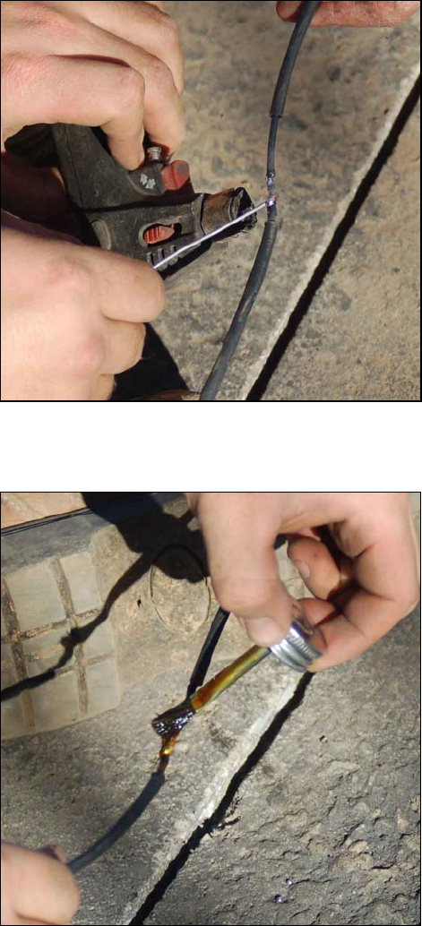
5. Apply some Oatey tinning flux to the joint.
6. Heat the joint with a soldering torch.
7. When hot enough, remove the torch and
touch the solder to the joint. If hot enough, the
solder will flow through and around the
strands.
Soldering the splice
8. Once the joint has cooled, apply ScotchKote
to the soldered connection.
Applying ScotchKote sealer
Installation Photographs
GATEKEEPER SYSTEMS INC.
2007 CART CONTAINMENT MANUAL
Page 48
9. Slide the heat shrink tubing back over the joint
so that the tubing extends about an inch past
the cut insulation on each end.
10. Use the torch to shrink the tubing tightly
around the joint.
Splice before heating the shrink tube
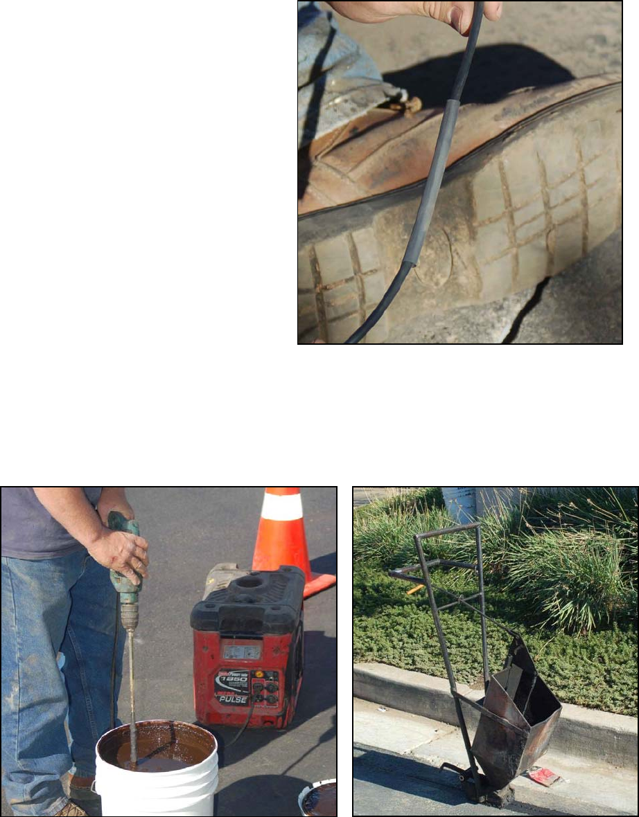
Sealing the Saw Cuts
Before sealing, mix the cold-pour asphalt sealant thoroughly,
using a drill and mixing wand
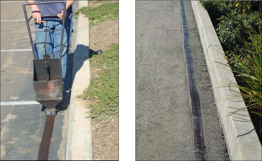
Use the SealMaster Cold-Pour Pot to apply the
sealer in an even manner.
Installation Photographs
GATEKEEPER SYSTEMS INC.
2007 CART CONTAINMENT MANUAL
Page 49
Asphalt sealant being poured. The pour pot is pulled,
not pushed along the cut.
The finished product.
Installation Photographs
GATEKEEPER SYSTEMS INC.
2007 CART CONTAINMENT MANUAL
Page 50
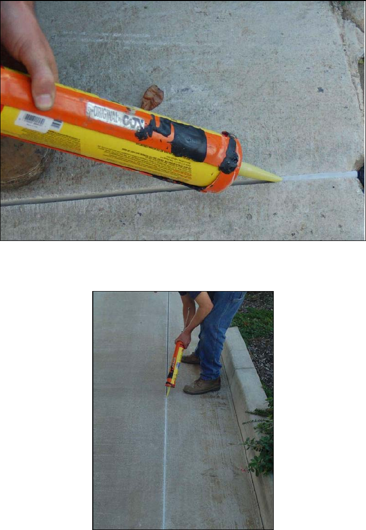
Sealing Concrete
Whenever possible, use existing expansion joints for cutting in concrete. This speeds the job and saves wear
and tear on the saw blade.
Seal with a self-leveling sealer such as QuikRete or SikaFlex, designed especially for use on concrete. DO NOT
use asphalt sealer on concrete.
Always fill the cut completely with sealer. Any gaps will settle and become water collectors.
Installation Photographs
GATEKEEPER SYSTEMS INC.
2007 CART CONTAINMENT MANUAL
Page 51
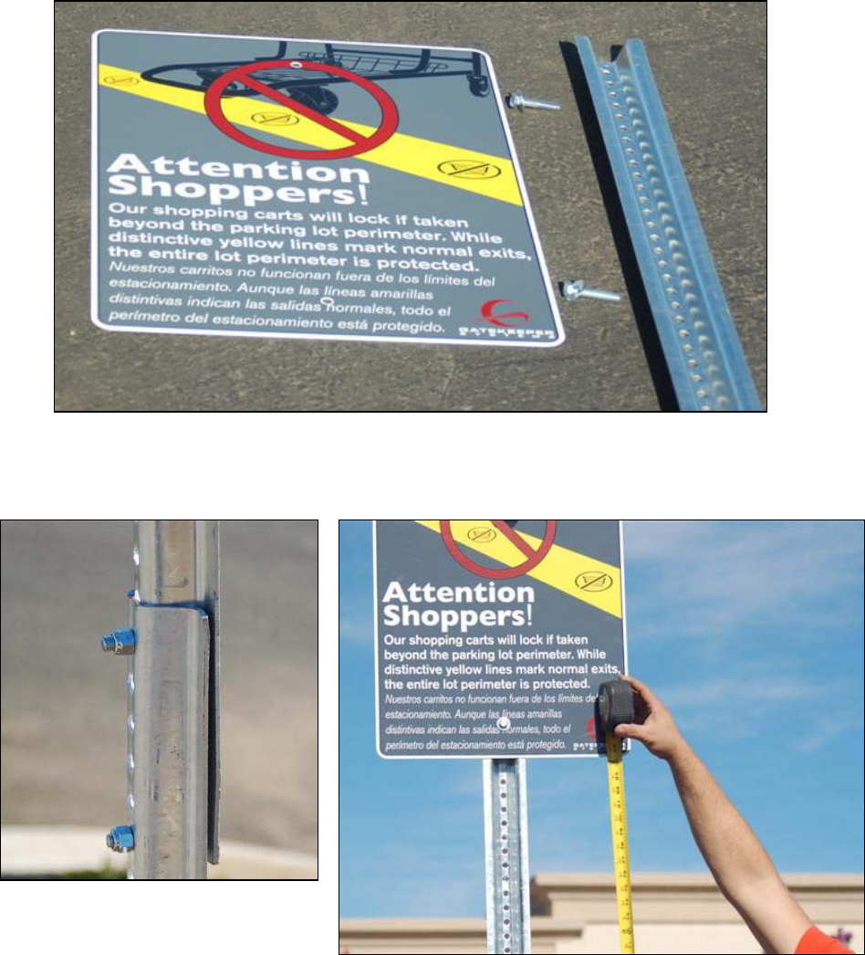
Installing Parking Lot Signs
“Attention Shopper” signs must be installed with the bottom of the sign at least 7 feet above the ground. This will
require two pieces of 6 foot long U-channel, bolted together.
The signs should be installed at the very top of the U-channel with the back of the sign against the wide (flared)
side of the U-channel.
Two pieces of 6 foot U-channel bolted
together
To ensure the safety of store patrons, the bottom of the sign should be
at least seven (7) feet above the ground.
Installation Photographs
GATEKEEPER SYSTEMS INC.
2007 CART CONTAINMENT MANUAL
Page 52
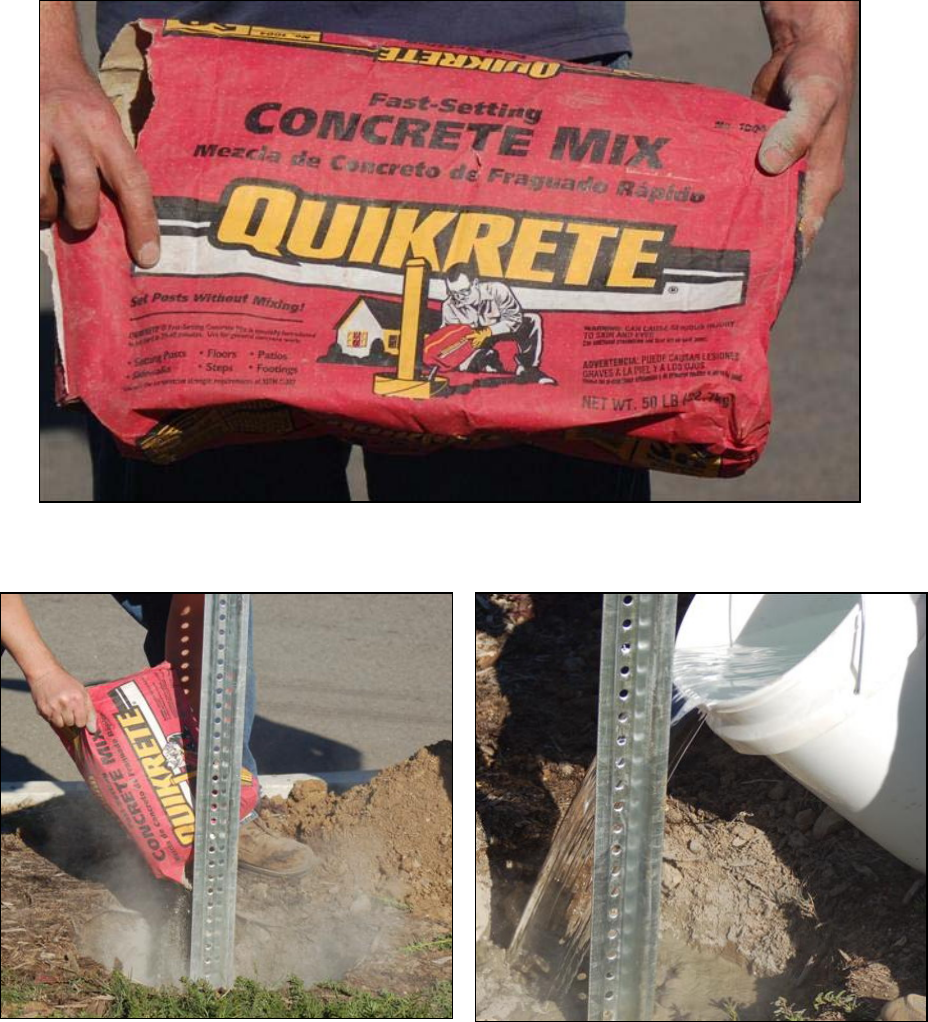
Setting the Sign Posts
Use QuikRete fast setting concrete mix to anchor the sign posts into the landscaping.
Set the post into the hole and pour the dry QuikRete
evenly around the base.
Pour water into the hole and mix. Make sure to keep the
post absolutely vertical while the QuikRete sets up.
Installation Photographs
GATEKEEPER SYSTEMS INC.
2007 CART CONTAINMENT MANUAL
Page 53
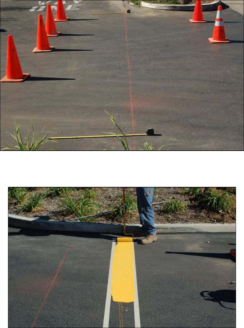
Containment Zone Striping
Striping should be placed approximately three feet from the antenna line (indicated by the chalk line in the photo
below). Block off the area with traffic cones to prevent automobile traffic from crossing over the stripe until it is
dry.
Use masking tape, placed nine inches (9”) apart. This will ensure a clean, straight stripe. Use a nine-inch (9”), ¾”
NAP paint roller to apply the yellow traffic paint.
Installation Photographs
GATEKEEPER SYSTEMS INC.
2007 CART CONTAINMENT MANUAL
Page 54
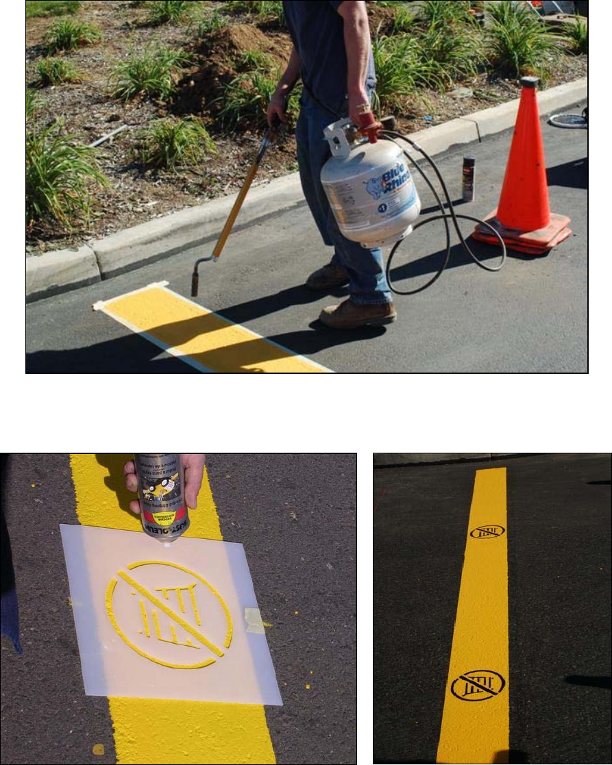
Painting the Stencils
A blowtorch can be used to cut down the drying time.
Center the shopping cart stencil on the stripe and paint with black
traffic paint. Stencils should be spaced approximately five feet (5’)
apart.
A finished stripe with stencils.
ExitManager
GATEKEEPER SYSTEMS INC.
2007 CART CONTAINMENT MANUAL
Page 55
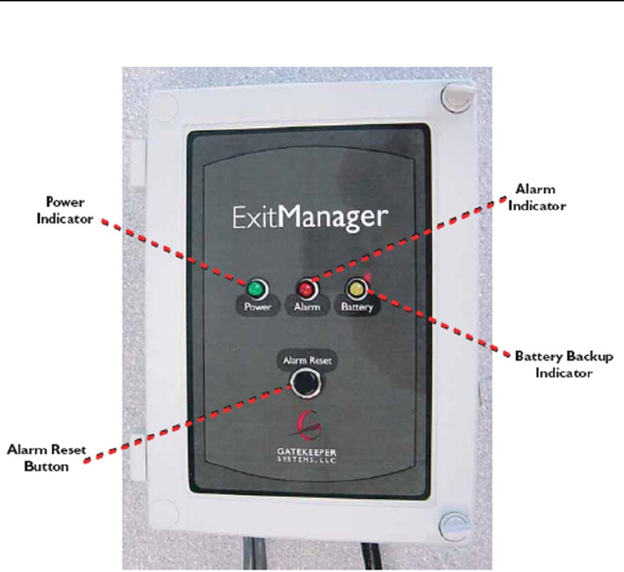
6 ExitManager
ExitManager Front Panel
ExitManager
GATEKEEPER SYSTEMS INC.
2007 CART CONTAINMENT MANUAL
Page 56
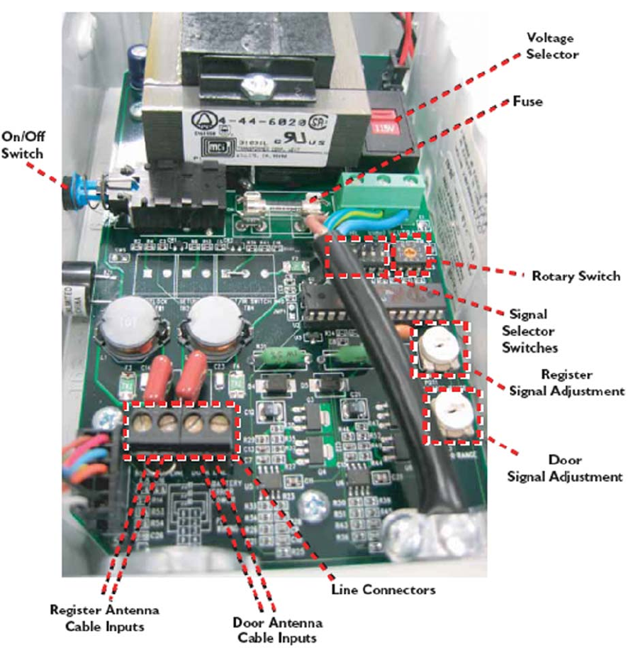
ExitManager – Inside Case

ExitManager
GATEKEEPER SYSTEMS INC.
2007 CART CONTAINMENT MANUAL
Page 57
ExitManager Settings
ExitManager can be configured to generate a signal for a Standard Outdoor GS1 application, a Standard Indoor
GS1 application, or a Standard Indoor Purchek application, based on the settings of the Signal Selector switches
shown in the tables below.
Selector Switch
Settings:
1 ▲ 2 ▲ 3 ▼ 4 ▼ 5 ▼ 6 ▼
Outdoor GS2 Application
(One locking line)
Cable Termination Settings:
• Locking Antenna terminates at the “Register Line” Loop Connector
• Jumper Is Inserted into the Cable Inputs at the “Door Line” Loop
Connector
Rotary Switch Setting: 1
Selector Switch
Settings:
1 ▲ 2 ▼ 3 ▲ 4 ▼ 5 ▼ 6 ▼
Indoor GS2 Application
(One lock line and one
unlock line)
Cable Termination Settings:
• Locking Antenna terminates at the “Register Line” Loop Connector
• Unlocking Antenna Terminates at the “Door Line” Loop Connector
Rotary Switch Setting: 0
Selector Switch
Settings:
1 ▼ 2 ▼ 3 ▼ 4 ▼ 5 ▼ 6 ▼
Indoor Purchek
Application
Cable Termination Settings:
• Locking Antenna terminates at the “Door Line” Loop Connector
• Unlocking Antenna Terminates at the “Register Line” Loop Connector
Rotary Switch Settings to set Entry Permission Timings (Setting – Timing)
• 0 - 2 minutes
• 1 - 15 minutes
• 2 - 10 minutes
• 3 - 30 minutes
• 4 - 1 hour
• 5 - 3 hours
• 6 - 2 hours
• 7 - 1 minute
Indoor Cart Containment Systems
GATEKEEPER SYSTEMS INC.
2007 CART CONTAINMENT MANUAL
Page 58
7 Indoor Cart Containment Systems
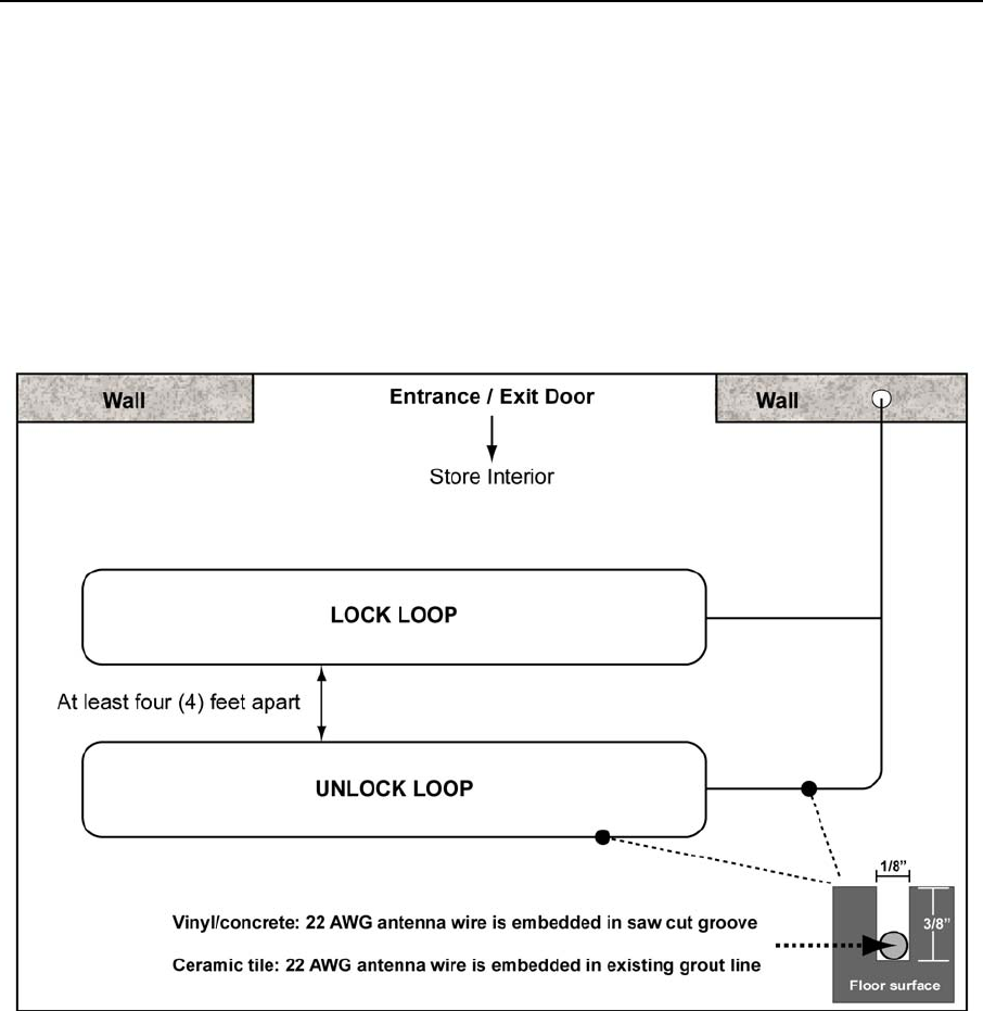
System Layout
Using the ExitManager in combination with 22AWG antenna, it is possible to configure a cart containment
system at the interior of a store’s exit. Often times these systems are configured to provide an unlocking loop, in
addition to a locking loop. This additional loop allows customers and store personnel to pull a locked shopping
cart backwards two to three feet and unlock the wheel, eliminating the need for a store attendant with a Cartkey.
The antenna of an indoor system is generally embedded into the concrete slab below the carpet or vinyl-covered
tile, or sometimes, in the grout lines of a ceramic tile floor surface. For systems where there is no electronic
article surveillance (EAS) system in place, each loop or lock box should be configured to be two-feet wide, with a
minimum of four-feet of separation between the two lock boxes. An example lock / unlock configuration is
illustrated below.
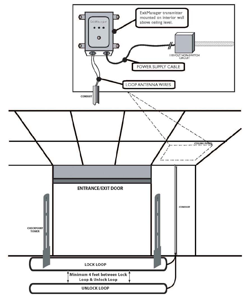
In this example, the ExitManager is attached to the wall above the ceiling at the right side of the store exit. The
22AWG antenna is the routed down the interior of the wall and cut into the concrete slab below the floor surface.
Indoor Cart Containment Systems
GATEKEEPER SYSTEMS INC.
2007 CART CONTAINMENT MANUAL
Page 59
System Layout with EAS System
In instances where there is an EAS system, it is best to configure the locking loop to be located either directly in
front or behind the EAS towers, or to wrap around the EAS towers (see diagram on page 40). Installations with
an EAS tower will require the locking line to be set to an output where the locking signal extends beyond the
range of the EAS tower signal interference. It is important that the unlock loop be placed NO LESS THAN FOUR
(4) FEET away from the locking line. It is best to use your SmartKey to determine the exact location where you
can recognize a locking signal and then place the unlock line a minimum of one (1) foot beyond that point.

Store Training
GATEKEEPER SYSTEMS INC.
2007 CART CONTAINMENT MANUAL
Page 60
8 Store Training
Training the Store Personnel
Properly training the store personnel is an important part of the GS2 System installation. Take care in
representing yourself in a professional manner. Whoever is performing the training should change into a fresh
Gatekeeper or Company work shirt prior to the training. Educating the customer on all aspects of the GS2
System at time of installation will serve to improve the performance of the overall system.
The store personnel must be trained on the following features:
• Make certain that the store manager understands the perimeter boundary by walking the entire perimeter
antenna with him/her.
• Instruct them to check the system daily by taking a cart equipped with the GS2 Wheel to several locations
along the system perimeter to insure that the system is fully operational. If the GS2 Wheel does not lock at
the perimeter antenna, repeat the test with several other carts. If none of carts appear to work properly,
place a service call to building maintenance or Gatekeeper Systems.
• With an equipped cart, show the customer how a cart will lock when approaching the perimeter. It is
important that the customer understand that the GS2 Wheel will begin to lock three to four feet (3’ to 4’) in
front of the perimeter antenna.
• Train the customer on how to unlock a locked cart. To unlock wheels, hold the cart key approximately 1.5 to
3 feet from the wheel and depress the unlock button while moving the key toward the wheel. The wheel will
be unable to lock again for 10-15 seconds, due to a programmed delay which allows a cart to be
removed from the influence of the locking zone.
• Train the customer how to change a battery on the CartKey. If there is difficulty locking and/or unlocking
wheels, train the store to check the battery status in the CartKey.
• Perform training on the operation of the CentralTransmitter: the push button on the exterior of the
CentralTransmitter reverses the signal of the system for approximately 30 seconds, unlocking all carts
locked on the perimeter antenna. Train them on the meaning of the Status Lights and Audible Alarm.
• Walk the manager through the User Manual, included with the CentralTransmitter. Instruct the manager to
keep the User Manual in a safe location for future reference. Indicate the 24-hour, toll-free Customer
Support number printed on the User Manual and on the front door of the CentralTransmitter
Upon the conclusion of training, complete the GS2 Training Acknowledgement and have it signed by the
designated Store Trainer. You may also use the form to confirm receipt of equipment that is given to store
personnel in person, such as CartKeys.

Store Training
GATEKEEPER SYSTEMS INC.
2007 CART CONTAINMENT MANUAL
Page 61
GS2 TRAINING ACKNOWLEDGEMENT
AND EQUIPMENT RECEIPT FORM
As the designated lead store trainer for operation of the Gatekeeper GS2 Cart Containment System, I
acknowledge the installation of the system has been completed to the store’s satisfaction, the installation was
completed in a workmanlike and professional manner, and that I possess a solid understanding of the system
and will utilize the training and documentation I have received to train new employees as store management
deems necessary.
(Please print clearly)
STORE NAME & NUMBER NAME AND TITLE DATE
I acknowledge I have taken possession of _____ Emergency Maintenance Kits from Gatekeeper Systems and
______ CartKeys from Gatekeeper Systems.
SIGNATURE TITLE DATE
STORE COMMENTS:

Store Training
GATEKEEPER SYSTEMS INC.
2007 CART CONTAINMENT MANUAL
Page 62
Installation Walk Through
Store Name: Store Number:
1.Was installation was completed in a workmanlike and professional manner?
Yes No
2. Did the installation crew leave the parking lot in a clean condition?
Yes No
3. Is the antenna installed according to the approved site plan?
Yes No
4. Is the perimeter antenna sealed properly?
Yes No
6. Are there any follow up items that need to be completed?
Yes No
If yes, please list the items below:
Initial here: ________________

Store Training
GATEKEEPER SYSTEMS INC.
2007 CART CONTAINMENT MANUAL
Page 63
GATEKEEPER SYSTEMS
GS2 CART CONTAINMENT SYSTEM
QUICK START SYSTEM GUIDE
The following is a brief summary of some of the highlights of the Gatekeeper User Manual and should be used in
conjunction with the information outlined in the manual.
• Test the system daily. Equipped with a CartKey, push a cart to the perimeter boundary to ensure the GS2
Wheel locks. Unlock the wheel using the CartKey.
• If the GS2 Wheel does not lock, test a second cart. If the second cart does not lock, check the
CentralTransmitter (typically located in the receiving, customer service or reception area). Confirm that
power is being supplied to the unit. If the perimeter antenna has been damaged, the red light on the front of
the CentralTransmitter will flash. Contact Gatekeeper Customer Service at 888-808-9433..
• Ensure that each employee responsible for retrieving carts is equipped with a CartKey while they are on
duty. Make sure all new employees are aware of the location of the perimeter boundary.
• If the store utilizes an automatic “cart pusher”, each cart must be unlocked before adding it to the line. Never
place a locked cart into a cart corral.
• Be aware that each CartKey has the ability to both lock and unlock carts. To lock a cart with a CartKey,
simply press the red “Lock” button.
• When the CartKey battery is low, the display light on the face of the CartKey will flash. Using a coin, remove
the rear battery cover and replace the battery. See User Manual for detailed instructions on battery
replacement.
• If The GS2 Wheel does not unlock after depressing the “Unlock” button on the CartKey, you can reset the
Wheel by performing the following steps:
1. Hold the CartKey approximately 18” to 36” away from The GS2 Wheel. For best results, angle the
bottom of the CartKey so it is oriented towards The GS2 Wheel.
2. Depress the “Lock” button. This will reset The GS2 Wheel to accept the unlock signal.
3. Next, depress the “Unlock” button. This should unlock The GS2 Wheel. If this fails, notify the store
manager or lead store trainer.
If at any time you require product support or service, please contact
Gatekeeper’s 24-hour Toll Free Customer Service Hotline at:
888-808-9433

Communication and Documentation
GATEKEEPER SYSTEMS INC.
2007 CART CONTAINMENT MANUAL
Page 64
9 Communication and Documentation
Communication
Communication with the Gatekeeper office is an important aspect of your partnership with Gatekeeper.
Upon first arrival to the job site:
4. Call (888) 808-9433 x. 35.
5. Press ‘35’ when the recorded message begins.
6. When prompted, provided the following information:
• Store name & number
• Installer name
• Ticket number
• Arrival time
Upon completion of the job:
1. Call (888) 808-9433 x. 35
2. Press ‘35’ when the recorded message begins.
3. When prompted, provided the following information:
• Store name & number
• Installer name
• Ticket number
• Departure time
• Total antenna linear footage
Documentation
Once an installation is complete, it is imperative that the following documentation is completed and sent to the
Gatekeeper office within 48 hours:
• Completed Installation Work Order (see
sample that follows)
• Training Acknowledgement
• Completed as-built drawing. Using the site
plan mark your splice locations, also make
any changes in antenna route.
• Pictures
• Central Transmitter location after it is
mounted (label the picture as CT01).
• Asphalt sealed. (label the picture as
ASPHALT01)
• Concrete sealed (label the picture as
CONCRETE01)
• Parking lot sign (label the picture as
SIGN01)
• Containment zone stripe (label the picture
as STRIPE01).
• Front of store (label the picture as
STORE01)
Problem Resolution
Should you encounter any technical issues, site plan layout challenges, or have scope of work questions while
working on an installation or performing a service visit, please call the Regional Field Service Supervisor for the
region you are working in (this applies to third party contractors):
• Paul Kammerer – West Region (West of the Mississippi) (949) 689-0454 mobile
• David Spence – East Region (East of the Mississippi) (804) 307-8048 mobile

Troubleshooting
GATEKEEPER SYSTEMS INC.
2007 CART CONTAINMENT MANUAL
Page 65
10 Troubleshooting
Diagnosing CentralTransmitter and Perimeter Antenna Issues
This section provides several flowcharts and processes for troubleshooting problems with the CentralTransmitter
and perimeter antenna. Gatekeeper Systems Customer Service will attempt to gather information during the
initial service call from the client, but sometimes the only information the technician may have on arrival is that
“…the system doesn’t work…”
The first action when arriving on site is to contact the store manager for an active store, or the construction
superintendent for a store that is still under construction.
1. Introduce yourself to the person in charge and let them know:
• why you’re at their store,
• what you plan to do,
• what times you plan to be working,
• about how long it should take,
• the areas of the store to which you will need access,
• how your work might impact their store operation.
2. Collect as much information as you can:
• ask the manager to describe the problem from their perspective,
• when did the situation begin,
• is the problem intermittent or ongoing,
• has there been any recent construction, landscaping, power outages, etc.,
• are any other systems in the store currently experiencing problems?
3. Do a quick visual check of the CentralTransmitter area. Look for loose power cords, external damage to the
box or conduit and any other obvious signs.
4. Start with the Main Troubleshooting Flow Chart on page 66. Letters in bold (A, B, C, D…) in the main flow
chart refer to secondary flow charts or processes in this manual. The titles and page numbers for the
secondary flow charts are shown at the bottom of the main flow chart page.
Troubleshooting
GATEKEEPER SYSTEMS INC.
2007 CART CONTAINMENT MANUAL
Page 66
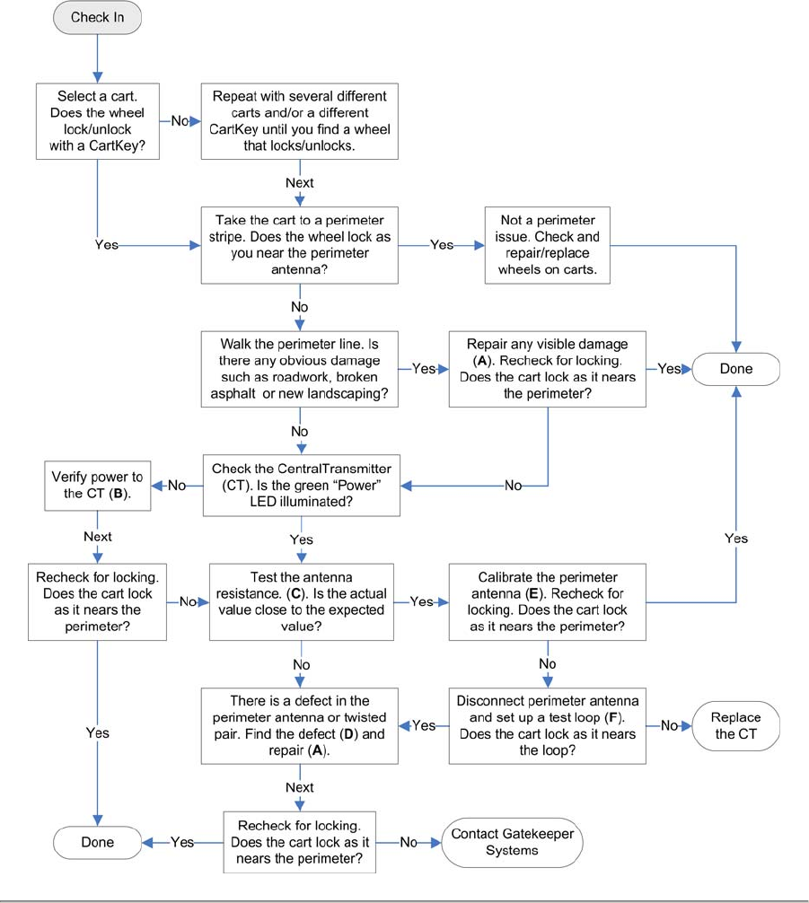
Main Troubleshooting Flow Chart
A – Splicing the Perimeter Antenna, page 46 D – Finding a Perimeter Antenna Defect, page
69
B – Verifying Power to the CT, page 67 E – Calibrating the CT, page 30
C – Checking Antenna Resistance, page 68 F – Setting Up a Test Loop, page 73
Troubleshooting
GATEKEEPER SYSTEMS INC.
2007 CART CONTAINMENT MANUAL
Page 67
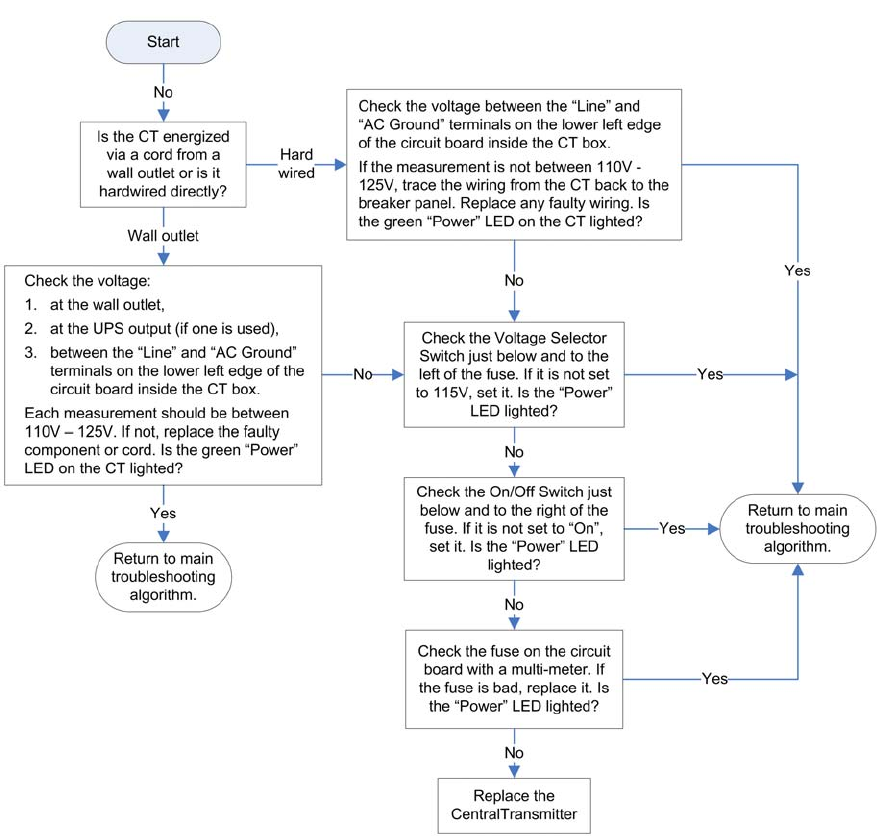
Verifying Power to the CentralTransmitter
This flow chart is used to verify that there is an adequate power supply to the CentralTransmitter (CT). The flow
chart assumes that the store power is on and that there is a voltage output from the circuit breaker supplying the
CT is between 110V – 125V.
This flow chart can be used as a “stand alone” troubleshooting tool, but is most effective when used as part of
the main troubleshooting flow chart.
Troubleshooting
GATEKEEPER SYSTEMS INC.
2007 CART CONTAINMENT MANUAL
Page 68
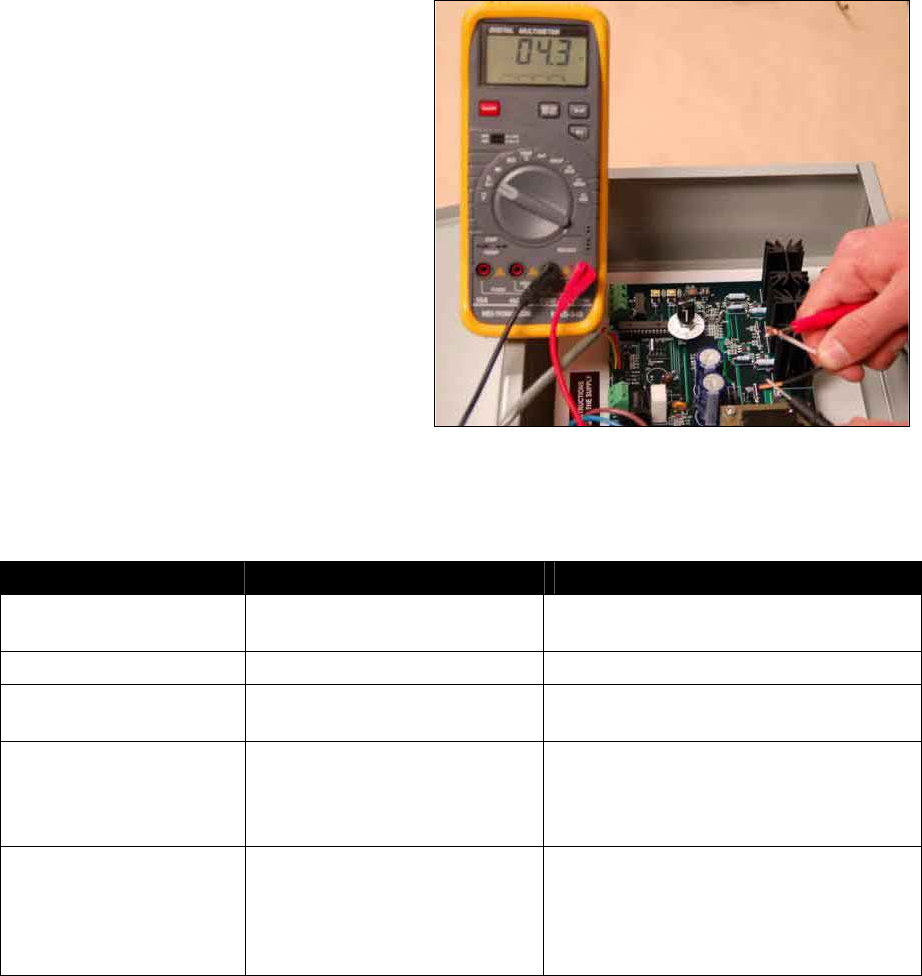
Using the multimeter to determine total antenna
Checking Antenna Resistance
Set the multimeter to the ohm scale and touch the two leads together. This gives you a baseline value, which
should be zero. If the value is not zero, calibrate the meter. If it is not possible to calibrate the meter to zero,
make sure to add the baseline value to any measured value you get when testing the antenna resistance.
14 AWG antenna used with Gatekeeper Systems antennas will have a resistance of approximately 2.2 ohms per
1,000 feet of antenna. The value for twisted pair antenna will be slightly higher.
1. Use the formula above to calculate the expected resistance. Write the number down.
2. Turn off the power to the CT. Do not use the
toggle switch, this de-energizes the board but
there is still power in the transmitter. If the
transmitter is hard wired (no cord), find the
circuit breaker and de-energize the breaker.
3. Remove the loop antenna from the terminal
block on the circuit board. Reading with the
antenna connected will give a false value.
4. Touch one of the meter probes to one end of
the antenna and one to the other end.
5. Record the reading and note whether the
reading is steady or fluctuating.
6. Compare the expected value and the actual
value. Use the table below to determine the
probable cause of the malfunction, then return
to the Main Troubleshooting Flow Chart and
continue the troubleshooting process.
Keep in mind that different multimeters have different sensitivities. Your results may not be exactly like
the examples.
Value Example Probable Cause
Close to expected 2.0 – 2.4 ohms for a 1000 foot
antenna.
Antenna is probably in good shape without
nicks, breaks or shorts.
0 0 There is a complete break in the antenna.
Much lower than expected 1 ohm for a 1000 foot antenna. This is usually due to a short in the twisted
pair leading from the CT to the antenna.
Much higher than expected 1 K-ohm for a 2,000 foot antenna This is frequently seen when a piece of
metal has been driven through the wire,
such as a sign pole or a metal spike for a
parking bumper.
Fluctuating Increases then decreases rapidly. This is caused by a capacitance in the
antenna, which means a non-insulated cable
bleeding to ground. This could be at a bad
splice or nick in the insulation that allows a
short into wet ground.
Troubleshooting
GATEKEEPER SYSTEMS INC.
2007 CART CONTAINMENT MANUAL
Page 69
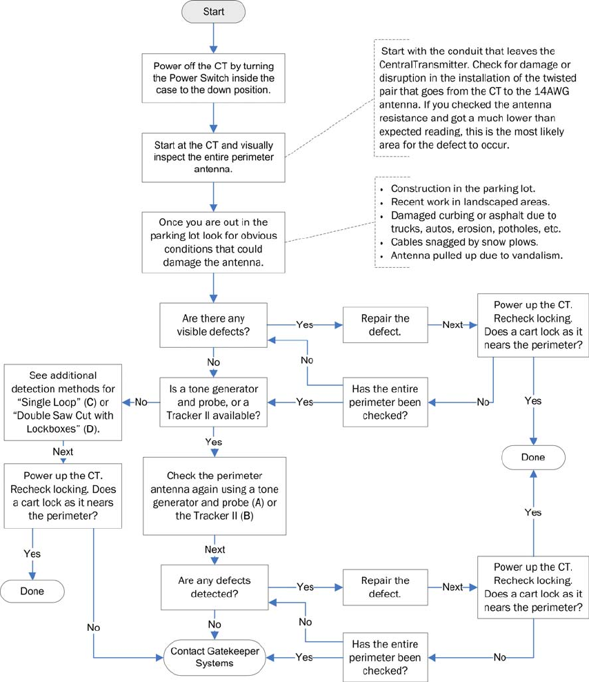
Finding a Perimeter Antenna Defect
This flow chart details the process for detecting defects in the perimeter antenna. As with the main flow chart,
secondary processes are indicated by bolded capital letters (A, B, C…) whose titles and page numbers are listed
at the bottom of the page.
A – Using a Tone Generator and Probe, page 70 C – Single Loop Installations, page 72
B – Using the Tracker II, page 71 D – Double Cut and Twisted Pair with Lockboxes, page 72
Troubleshooting
GATEKEEPER SYSTEMS INC.
2007 CART CONTAINMENT MANUAL
Page 70
Antenna Troubleshooting with a Tone Generator and Probe
One way of finding a break in the perimeter loop is by using a tone generator and probe combination. This tool is
used in the telecommunication industry to locate phone cables and designate pairs, but is also very useful for
locating breaks in the perimeter antenna.
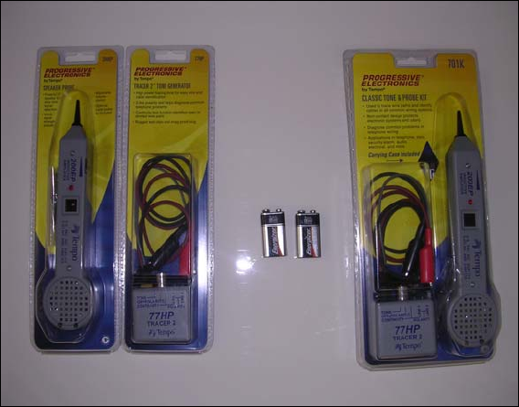
Gatekeeper Systems recommends the Progressive Electronics 77HP Tracer 2 Tone Generator and the
Progressive Electronics 200EP Speaker Probe. The benefits of these models are in the features of the probe:
• 2” speaker with adjustable volume,
• Red LED visual signal strength indicator,
• Terminals to accommodate headsets.
The tone generator and probe can be purchased as a kit, or as separate components. Both configurations are
shown below. Each component requires a separate 9-volt battery.
The tone generator and probe should always be used with a set of headphones, as ambient noise makes it
difficult to hear the subtle tone changes that indicate a break or short.
Tone generator and probe
To detect perimeter antenna breaks using the tone generator and probe:
1. Connect the tone generator to the two antenna output leads in the loop. This generates a signal down both
sides of the loop.
2. Turn the tone generator on and then follow the perimeter loop with the speaker probe held near the
perimeter wire.
3. When you reach an area where the volume of the tone drops way down, mark the spot.
4. Continue walking slowly until the volume picks back up. Make a second mark.
5. In a single loop configuration with 2,000 or more feet the distance between the two marks is usually 7 to 10
feet. The damaged section will be found in the center third.
Troubleshooting
GATEKEEPER SYSTEMS INC.
2007 CART CONTAINMENT MANUAL
Page 71
Antenna Troubleshooting with the Tracker II
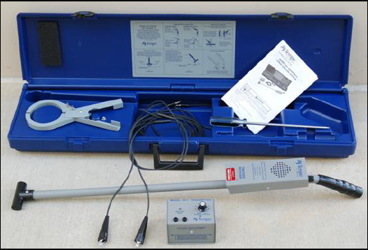
The Model 501 Tracker II is designed to
locate the path and depth of buried cable,
service wires, metallic pipe or conduit, and
locate the end of a cut cable. The Tracker II
transmitter is housed in an aluminum case
and is powered by eight 1.5v AA batteries.
The transmitter has an on/off control knob
which is also used to adjust the output level
and a LED indicating the battery condition.
Effective range is greater than 4,000’ in
length and for depths up to 7’. The receiver
is encased in an aluminum housing,
mounted with an antenna and is powered by
a 9v battery. The receiver has a speaker for
listening to the signal, a meter for monitoring
the signal level, a handset jack, an on/off
volume control knob and an antenna for detecting the tone over the cable.
The tone generator and probe should always be used with a set of headphones, as ambient noise makes it
difficult to hear the subtle tone changes that indicate a break or short.
1. Plug the cord set leads into the transmitter and clip the leads together.
2. Turn the transmitter control on and rotate fully clockwise. A bright LED indicates enough battery power. If the
battery test light is not lit brightly change the batteries following the directions on the Transmitter housing.
3. Turn the transmitter off.
4. Connect the transmitter to the perimeter antenna:
• Twisted Pair - connect a lead to each separate conductor within the cable. It is important to make sure
that the shield and drain are not touching either conductor.
• Antenna Loop Cable- connect one lead to the conductor and the other lead to earth-ground. This can be
done via a screw driver or to a conduit that has been tested with a ground plug.
5. Turn the receiver control on and rotate clockwise to the 12:00 position.
6. Turn the transmitter on to the #3 position and pass the receiver antenna close to the transmitter. Any
indication from the receiver indicates acceptable battery condition. If the receiver has no indication as it
passes near the transmitter, change the batteries follow the directions on the receiver housing.
7. Walk along the perimeter antenna path with the end of the receiver held near the ground. The signal will
diminish rapidly and be lost as you near and then pass the break.
8. Double back and check again. Make a mark where the signal disappears.
9. Reconnect the transmitter leads to the other side of the antenna and test from the other direction to confirm
the location of the break before exposing the cable.
This same procedure can be used to locate cable splices and damaged cable. As the signal begins to fade mark
the asphalt. You will see a larger area of weak signal.
Troubleshooting
GATEKEEPER SYSTEMS INC.
2007 CART CONTAINMENT MANUAL
Page 72
Troubleshooting Single Loop Installations
With a single loop installation the troubleshooting becomes more difficult if the cable shows no obvious damaged
areas. You must run a jumper cable across the loop breaking your loop up into smaller sections. This is difficult
in a busy parking lot so be careful! Your jumper needs to be twisted into a piece of the loop cable. Run the
jumper along side the existing cable. Follow the steps mentioned above and eliminate section by section. Once
the problem is isolated and found re-splice your test locations.
Troubleshooting Double Saw Cut and Twisted Pair with Lock Boxes
Once you complete your Ohm reading, twist the two antenna loop cables together to close the circuit. Take your
meter and walk the perimeter approximately half way around the locking zone. Look for an area where the cable
can be accessed easily. If need be you can dig up the conduit in a landscape area or carefully remove the sealer
in a section of parking lot. After exposing the cable, separate the loop into two sections. Because the cable is
closed at the transmitter end of the loop, you can measure both sides as separate loops. Keep in mind your
undamaged cable will read 2.2 ohms of resistance per 1,000 feet of cable. By measuring the two separate loops
you can determine which direction the break is. Do not re-splice the cable at this point as you will want to twist
the cable together to close off the bad section. Walk the perimeter cable again looking for any obvious damage.
Nothing obvious, repeat the above test each time breaking the loop in half. This will shrink the area to find the
damaged cable. Once the problem is isolated and found re-splice your test locations.
Replacing the Central Transmitter Fuse
Tools you will need:
• Circuit tester to check whether or not there is power to the fuse
• Fuse puller (not necessary, but strongly recommended - available at electronics or auto parts stores)
• Replacement fuse:
• For a 9100 Central Transmitter: T-LAC TIME LAG 500ma 250volt
• For a 9110 Central Transmitter: T-LAC TIME LAG 1amp 250volt
The fuse is located on the Central Transmitter board, and is labeled F2. To replace the fuse you must first
remove power to the transmitter.
1. Remove power to the Central Transmitter by pulling the plug from the receptacle. If there is a battery back-
up make sure you are pulling the transmitter plug, not the plug from the battery back-up. Do not depend on
the toggle switch, this de-energizes the board but there is still power coming into the fuse. If the transmitter
is hard wired (no cord), find the circuit breaker and de-energize the breaker.
2. Check the fuse with your electric meter and make sure there is no power to the fuse. Remove the fuse. The
fuse is in a tight holder on the board, and is surrounded by sensitive electronic parts; care needs to be taken
when removing it. There is a fuse removal tool available at electrical and auto part stores.
3. Replace the fuse with one of the following:
4. Plug in the power cord/ turn on the circuit breaker.
5. Push the toggle switch to the up or on position.
6. At this point the Green LED should light, indicating that the transmitter is energized.
Troubleshooting
GATEKEEPER SYSTEMS INC.
2007 CART CONTAINMENT MANUAL
Page 73
Setting Up a Test Loop
When setting up a test loop, you bypass the perimeter antenna and attempt to lock a cart wheel using a small
local antenna hooked directly to the CentralTransmitter (CT).
1. Power off the CT by pulling the plug from the wall outlet or de-energizing the circuit breaker at the panel.
2. Disconnect the perimeter antenna terminals from the terminal block.
3. Create a small local loop by connecting 10-15 feet of 14AWG antenna wire to the antenna terminal blocks.
4. Make sure the Field Strength Adjustment potentiometer knob is turned all the way to zero (0).
5. Power up the CT.
6. Place a cart with a working Gatekeeper wheel about three (3) feet from the loop.
7. Slowly turn up the Field Strength Adjustment knob and listen for the sound of the wheel beginning to lock.
8. If the wheel has not locked by the time you reach about a quarter turn on the knob, the CT probably needs
to be replaced. It is usually not a good idea to turn the field strength any higher, as you may risk locking
carts in nearby store areas.
9. When finished, return to the Main Troubleshooting Flow Chart on page 66.
Coupling
Definition: Coupling is the association of two circuits or systems in such a way that power may be transferred
from one to the other.
In the context of Gatekeeper Systems, coupling may be present when the 7.8 kHz signal transfers from the
antenna cable to surrounding conductive materials. Conductive materials can include conduits, data cables,
pipes, and even moist ground. When the antenna crosses the path of any conductive material a signal is coupled
onto this material. The degree of coupling is determined by how efficient a conductor the material is and how
much output is being generated by the Gatekeeper CentralTransmitter.
A drain pipe (medium efficiency conductor) in the ground will absorb the signal but will travel only a small
distance. A conduit with conductors inside (good conductor) will carry the signal much further; if the circuits
inside the conduit are energized and carrying current, the signal will carry even further still. If the antenna path
runs parallel to the conductive material within the field of the signal, the coupling is stronger than if the paths
cross.
The best way to avoid coupling is to eliminate it in the installation process. By following the installation steps in
the manual you will avoid a high percentage of coupling issues. In some instances coupling cannot be detected
until the installation is complete. Due to the construction and remodel of retail establishments it is impossible to
foresee all coupling scenarios. It is in dealing with these situations that the following troubleshooting techniques
should be applied to eliminate this phenomenon.
Tools you will need:
• SmartKey GS1.1 and GS2
• Toner and Amplifier,
• Cable Tracker,
• Wheel and CartKey.
1. When you arrive at the store, find out from store personnel in which area(s) of the store or parking lot the
carts are locking and if it is occurring on a regular basis.
2. Take a cart from the store’s fleet and a matching test wheel from your stock, and any test device you may
have for this system. Some stores have a mixed fleet. The most common is GS1 mixed with GS1.1. The GS1
is the most sensitive wheel and should be your test wheel. A Smart Key will work with the GS1.1 and GS2. An
inductive amplifier will work on all circuits if there is not a lot of electrical noise.
Troubleshooting
GATEKEEPER SYSTEMS INC.
2007 CART CONTAINMENT MANUAL
Page 74
3. Make sure the test wheels work by cycling them with a CartKey. The coupling signal is usually weak and
hard to detect. Locking the wheel usually takes place when the shopper stops to load their cart or to inspect
the merchandise. Sweep the areas with the test equipment and pay close attention to floor drains, electrical
circuits, and building support beams. Note any areas of concern.
4. Check the CentralTransmitter. If this is a digital system the coupling can be duplicated without interfering
with store operations by sending an unlock signal through the system.
• Power down the CentralTransmitter.
• Place a jumper between the two poles on the unlock switch located on the door panel.
• Turn the output level up until the unlock signal is present in your areas of concern. If you are using a
wheel as your indicator, lock the wheel before sweeping the area and note the location where it begins
to unlock. Remember that there is a delay before you can relock the wheel.
• Once you see this signal, follow its source to see if the antenna cable is coupling with something that
can be changed. This may require splicing in a test cable around the affected side of the building. If you
can move the test cable to eliminate the unlock signal, this should also eliminate the coupling. This may
take several attempts. Once the signal is eliminated then retune the CentralTransmitter to its previous
state.
5. With the CentralTransmitter still transmitting the unlock signal, check the perimeter and adjust the output
level to receive the signal at the desired level. The recommended level is three feet from the perimeter
antenna. This provides you with approximately a six foot field.
6. With the CentralTransmitter still transmitting the unlock signal, re-sweep the areas of concern. Widen the
sweep and move slowly. Be confident that the signal is not present.
7. Power down the Central Transmitter and remove your jumper.
8. Power up the Central Transmitter and return to the areas where the coupling was taking place.
9. Re-sweep the area to insure that your test wheel and the store’s cart are no longer locking. Use your
SmartKey to be sure that you do not see a stray signal in any of these locations.
Troubleshooting
GATEKEEPER SYSTEMS INC.
2007 CART CONTAINMENT MANUAL
Page 75
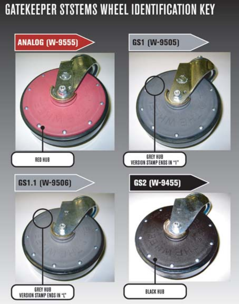
Mixed Wheel Environments
There may be several different types or revisions of Gatekeeper wheels at a single store location, especially if
the stores have been using the Gatekeeper System for some time, or carts are routinely moved between
different stores. It is important to understand the differences in these wheels and how they operate together (or
not). The four types of wheels you are most likely to encounter are Analog, GS1, GS1.1, and GS2, as shown in
the figure below.
Gatekeeper System wheel identification
Troubleshooting
GATEKEEPER SYSTEMS INC.
2007 CART CONTAINMENT MANUAL
Page 76
Analog wheels (Red in color) are NOT compatible with any other version of Gatekeeper wheel. If you are
providing service at an analog store, the only wheels that will work are the RED analog wheels. Grey or black
wheels will not work.
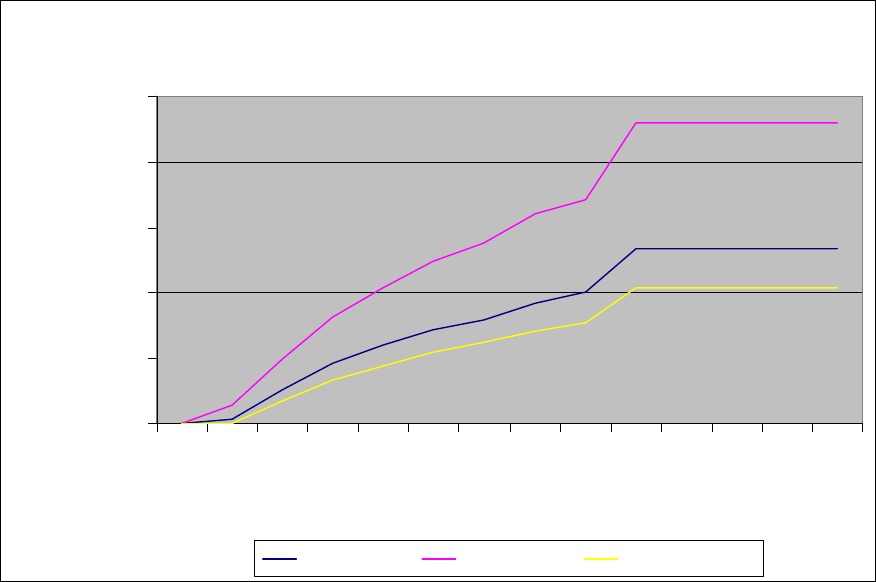
All versions of Grey and Black colored wheels will lock in a GS System digital environment; however, they will
react to the encoded signal at different ranges. The chart below indicates the locking range of three versions of
digital Gatekeeper wheels, in an environment with a 2,400 foot locking line and 40 feet of twisted pair.
D-9110 Digital 2400' with 40' of Twisted Pair
0.00
5.00
10.00
15.00
20.00
25.00
0 0.5 1 1.5 2 2.5 3 3.5 4 4.5 5 5.5 6 6.5
Transmitter Setting
Lock Distance (feet)
GS2 Wheel GS1 Digital GS1.1 Digital
Wheel locking distance as a function of transmitter setting
When servicing a digital store, it is important to note the type of wheel present at the store, before you replace a
wheel. As shown in the graph above, a GS2 or GS1.1 wheel will recognize the locking signal much closer to the
perimeter antenna than a GS1 Wheel. It is possible that a GS1 wheel will lock at the perimeter antenna, but that
a GS1.1 or GS2 wheel will not. The transmitter will need to be adjusted to allow for a locking range of
approximately one to two feet (1’ to 2’) for the GS1.1 or GS2 and three to four feet (3’ to 4’) for the GS1. So, in
the example illustrated above, you would adjust the CentralTransmitter to a pot setting of approximately 1 to
1.25, to achieve a locking range of two feet (2’) for the GS1.1 or GS2 and four feet (4’) for the GS1.
It is important that you NEVER leave a store without first checking the locking range of different wheel versions,
at several different locations on the perimeter antenna.

Material Specification Sheets
GATEKEEPER SYSTEMS INC.
2007 CART CONTAINMENT MANUAL
Page 77
11 Material Specification Sheets
This section contains specification for the following products.
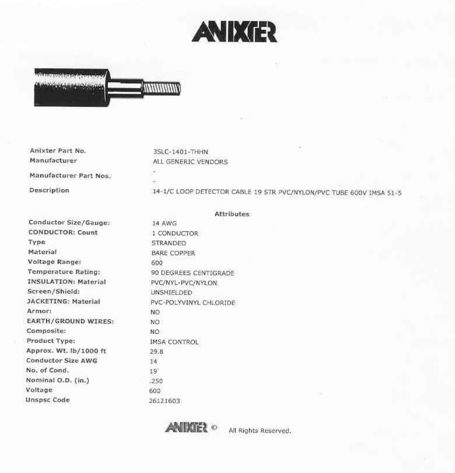
• 14awg single conductor traffic cable (Anixter)
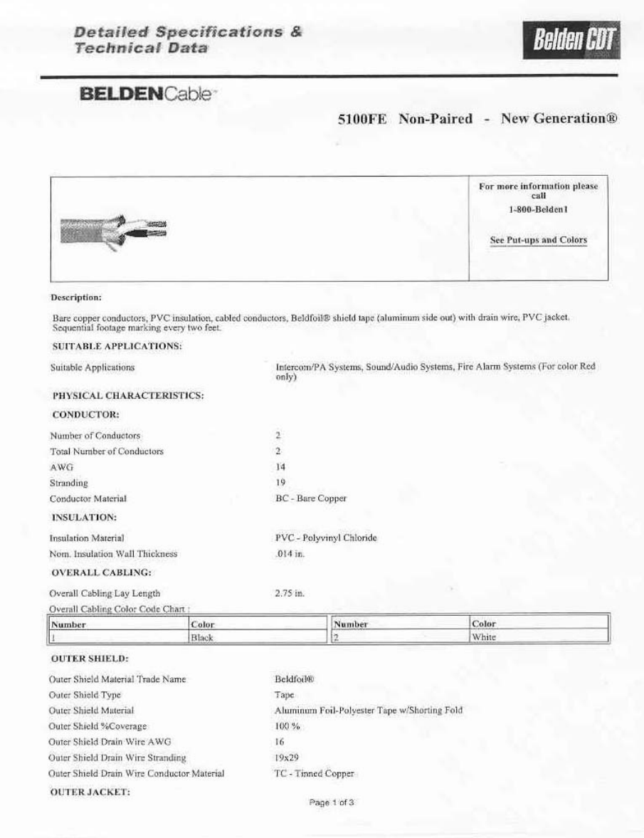
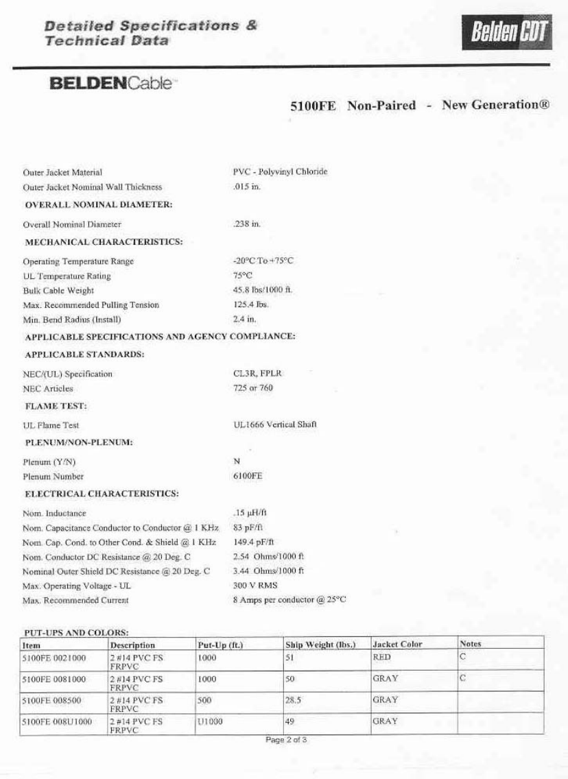
• 14awg two conductor twisted pair neutral (Belden)
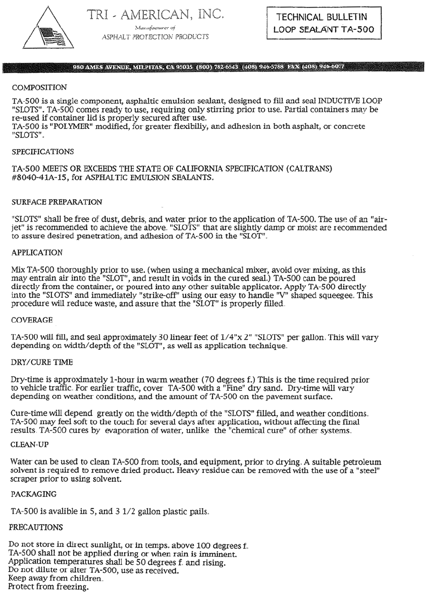
• Tri-American cold pour loop fill
• SealMaster cold pour loop fill
• Crackmaster hot pour applicator
• Crackmaster hot pour sealant
• QuikRete concrete sealant (level surfaces)
• QuikRete concrete sealant (un-level surfaces)
• 3M ScotchKote electrical coating
• Thermoline – thermoplastic line stripe
• Core Cut concrete saw
• Tempo Tracker II, model 501
• Kleen Sweep 27
Material Specification Sheets
GATEKEEPER SYSTEMS INC.
2007 CART CONTAINMENT MANUAL
Page 78
14AWG Traffic Loop
Material Specification Sheets
GATEKEEPER SYSTEMS INC.
2007 CART CONTAINMENT MANUAL
Page 79
Twisted Pair (neutral)
Material Specification Sheets
GATEKEEPER SYSTEMS INC.
2007 CART CONTAINMENT MANUAL
Page 80
Twisted Pair (neutral) (cont).
Material Specification Sheets
GATEKEEPER SYSTEMS INC.
2007 CART CONTAINMENT MANUAL
Page 81
Tri-American Cold Pour