Gatekeeper Systems W9200 Remote Controlled Locking Wheel User Manual USA TRAINING MANUAL 2007
Gatekeeper Systems, Inc. Remote Controlled Locking Wheel USA TRAINING MANUAL 2007
Contents
- 1. Users Manual Part 1a
- 2. Users Manual Part 1b
- 3. Users Manual Part 2
- 4. Users Manual Part 3
Users Manual Part 1b
Installation
GATEKEEPER SYSTEMS INC.
2007 CART CONTAINMENT MANUAL
Page 22
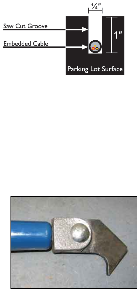
Saw Cutting the Marked Area
The 14AWG locking antenna is installed in asphalt or
concrete in a saw cut one inch (1”) deep and one-
quarter inch (1/4”) wide. Saw cutting at this depth
minimizes the chances of running into drain or power
transmission lines already placed in the ground, as
they are required to be buried at a much lower depth.
Saw cuts can be done using either a wet or dry cut
technique.
Dry saw cutting leaves no wet residue and is therefore
easier to clean up. The downside to dry saw cutting is
that it requires the proper equipment to capture the
airborne dry asphalt particles. If you choose to dry cut,
make sure that all technicians are equipped with
proper breathing apparatus and protective gear.
Wet cutting does not require respiratory protection, but
requires more work to clean up. Also, residue from wet
cutting must NEVER be allowed to run into the storm
drain or public streets. Most cities will levy a heavy fine
for this infraction.
All saw-cuts on concrete should be in a cold seam,
where possible.
Removing Saw Cut Residue
After sawing, the cut needs to be cleaned out. If you have
chosen to wet cut, clean out the saw cut and surrounding
area using a wet-dry shop vacuum and a high-pressure
water sprayer. In order to minimize staining, make sure to
clean the areas before the saw cut residue dries.
If you have chosen to dry cut, clean the saw cut and
surrounding area using the specified power sweeper. Any
excess residues should be cleaned out using the
Gatekeeper Hook, or if a Hook is not available, you may use
a straight edge screwdriver.
Wet / dry vacuum following saw cutter closely
Gatekeeper Hook for cleaning out the saw cut
Installation
GATEKEEPER SYSTEMS INC.
2007 CART CONTAINMENT MANUAL
Page 23
Installing the Perimeter Antenna
Once the saw cut is completed, and cleaned, the next step is to install the 14AWG antenna. Place the antenna
wire spool onto a wire caddy and walk along the saw cut so that the wire rolls off the spool and into the cut.
Follow with the Gatekeeper Antenna Roller to press the antenna securely down into the cut.
At some point during the installation, you will need to run the perimeter antenna through landscaped areas
enclosed by concrete curbs. See “Perimeter Antenna through Curbs”, page 42 for detailed instructions.
Before trenching in the landscape, insure that you will not be encroaching upon any sprinkler system or electrical
lines. It is imperative that any antenna placed in the landscape areas be installed in conduit, as the conduit offers
corrosion, resistance and high impact protection. Take caution to insure that the antenna is installed away from
sprinklers, water valves, and other high maintenance areas. User your fish tape to pull the antenna from one end
of the PVC to the other end. Anytime PVC conduit is used it must be sealed where the conduit ends. Use
expansion foam to seal each end of the PVC conduit after the antenna has been installed. Always return the
landscape area to its original condition.
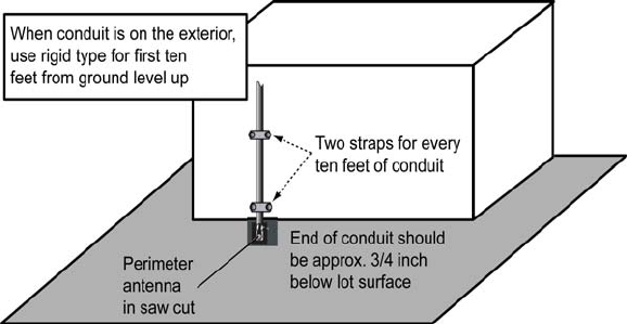
When it is necessary to bring the
antenna across the roofline or down
the side of the building, ½” rigid
conduit is used for the first ten feet
(10’), than ½” EMT conduit should
be installed and supported as
required by code. When conduit is
exposed to the elements,
compression connectors must be
used. Never install any antenna
above ground without running it
through conduit.
Anytime a conduit makes contact
with the ground surface, a one inch
(1”) penetration must be made and
repaired with the appropriate patch, i.e. concrete or asphalt. If the conduit contacts the earth, the conduit must be
no less than six inches (6”) deep. Use expansion foam to seal the ends of conduit when installing below ground.
When EMT is installed on a roofline, 2” x 4” wood blocks must be used to support the conduit. Use mastic to affix
the blocks to the roof. Never nail or screw the wood blocks to the roof. The roof surface should never be
penetrated.
For detailed instructions on making splices in the perimeter antenna, see 46.
Installation
GATEKEEPER SYSTEMS INC.
2007 CART CONTAINMENT MANUAL
Page 24
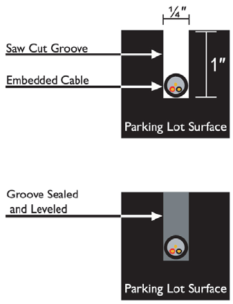
Sealing the Saw Cut
After the antenna is in place, the remaining ¾” of the saw cut is filled with asphalt sealer. The environment of the
installation will dictate the type of sealer to use. In dry weather conditions of 40º Fahrenheit or higher, a cold-pour
sealant and pour pot should be used. Gatekeeper approved
sealants for asphalt include OverKote and SealMaster. Gatekeeper
approved sealants for concrete include SikaFlex or Vulcum. Make
sure that you have completely cleaned the surface of the asphalt
before applying sealer. When using cold pour asphalt sealant, mix
the sealer thoroughly before attempting to apply. Use an electric drill
with a mixing paddle for at least five (5) minutes to guarantee that it
is thoroughly mixed. To insure a professional looking installation,
make sure that the sealant is level with the top of the saw cut (see
diagram). If any settling, sags, or cracks develop during the curing
process, a second application will be required. While applying the
sealer into the saw cut, if there is any excess or over spill, use a V-
shaped squeegee to direct the excess into the saw cut and to obtain
an even application. It is advisable to use traffic cones and caution
tape to prevent any vehicle or customer traffic from crossing the
sealer for approximately 30 minutes while it is drying. It takes
approximately 24 hours for cold pour sealer to completely cure.
Cold pour sealant may not be used at temperatures below 40º
Fahrenheit or in wet conditions.
If cold or wet weather does not permit the use of a cold pour sealant, than a hot melt asphalt sealant will be
required. For hot melt installations, you will need a melting applicator, a heat lance, and hot pour crack sealant. It
is important to note that if the temperature is less than 40º Fahrenheit, you must use a heat lance to heat the
asphalt before applying the hot pour crack sealant. If the asphalt is not properly prepared with the heat lance, the
hot pour sealant will not adhere to the asphalt surface. Adjust the melting applicator to a temperature ranging
from 350º to 375º Fahrenheit and insert the crack sealant cubes. Gatekeeper’s approved Type 2 traffic cable
(IMSA 51-50) is rated to withstand a temperature of 400º Fahrenheit. When applying the hot pour crack sealant,
use the v-squeegee to direct the sealant into the crack.
Mounting the Central Transmitter
The CentralTransmitter should be mounted in a secure, accessible location, away from possible forklift impact or
any other hazards. The CentralTransmitter needs air flow for cooling; do not install in a small confined space.
Mount the unit to the wall, at least five (5) feet above the finished floor, using the pre-drilled holes on the back
chassis of the enclosure. A drill-hole template is included inside the shipping package for the CentralTransmitter.
The enclosure comes with pre-drilled access holes located at the bottom of the enclosure: one for the power
supply and one for the conduit containing the antenna. Any conduits entering the transmitter must be installed
neatly and anchored properly using EMT straps.
This is a good point in the installation to check the resistance in the perimeter antenna (see “Checking Perimeter
Antenna Resistance”, page Error! Bookmark not defined.). Write down your measurement on the sticker
located on the insider of the CentralTransmitter door.
Installation
GATEKEEPER SYSTEMS INC.
2007 CART CONTAINMENT MANUAL
Page 25
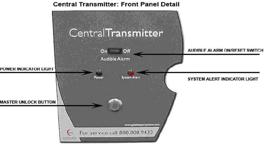
CentralTransmitter Front Panel
The exterior of the Central Transmitter has two LED’s that indicate system status. In addition, the Central
Transmitter has an audible alarm, to alert store personnel of a system disruption. The GREEN Power Indicator
LED will illuminate when the Central Transmitter is powered up and connected to a completed circuit (a
functioning perimeter antenna). If there is a break in the perimeter antenna, the RED System Alert LED will
illuminate (see diagram below).
The Master Unlock Button may be used to transmit a temporary unlock signal though the perimeter antenna. In
situations where the store has lost all of their CartKeys, the master unlock provides the ability to unlock any
locked wheels that are still located at the perimeter line. The master unlock signal is factory preset to transmit an
unlock signal for 30-seconds. Finally, the Audible Alarm Switch allows the store personnel to turn off the audible
alarm in the instance of a System Alert. Once the store personnel has been made aware of the system alert and
telephoned Gatekeeper Customer Service, the Audible Alert may be switched to the OFF position.
Installation
GATEKEEPER SYSTEMS INC.
2007 CART CONTAINMENT MANUAL
Page 26
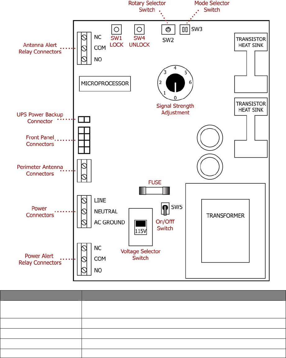
CentralTransmitter Circuit Board
Schematic diagram
Control Description
Mode Selector switch Specifies the type of signal (GS2 digital, analog, EP2000 or door mode) that will
be generated by the CT (page 30).
SW2 Rotary Selector switch Specifies single locking line or locking/unlocking lines (page 55).
SW1 Lock button Transmits a signal that locks all carts near the perimeter antenna.
SW4 Unlock button Transmits a temporary signal that unlocks all carts near the perimeter antenna.
Antenna Alert Relay Can notify an existing store system if the perimeter antenna is damaged (page
Installation
GATEKEEPER SYSTEMS INC.
2007 CART CONTAINMENT MANUAL
Page 27
Control Description
connector 31).
UPS Power Backup
connector
Front Panel connector Connects to the CT front panel indicator lights and control switches.
Perimeter Antenna connector Terminals for connecting the perimeter antenna to the CT.
Power connector Terminals for connecting the AC power lines to the CT.
Power Alert Relay connector Can notify a store system if power to the CT is cut off (page 31).
Voltage Selector switch 115/230 V selector. US settings are 115V.
SW5 On/Off switch Cuts power to the circuit board. Does NOT deenergize the system.
Fuse Current overload protection for the board (page 72).
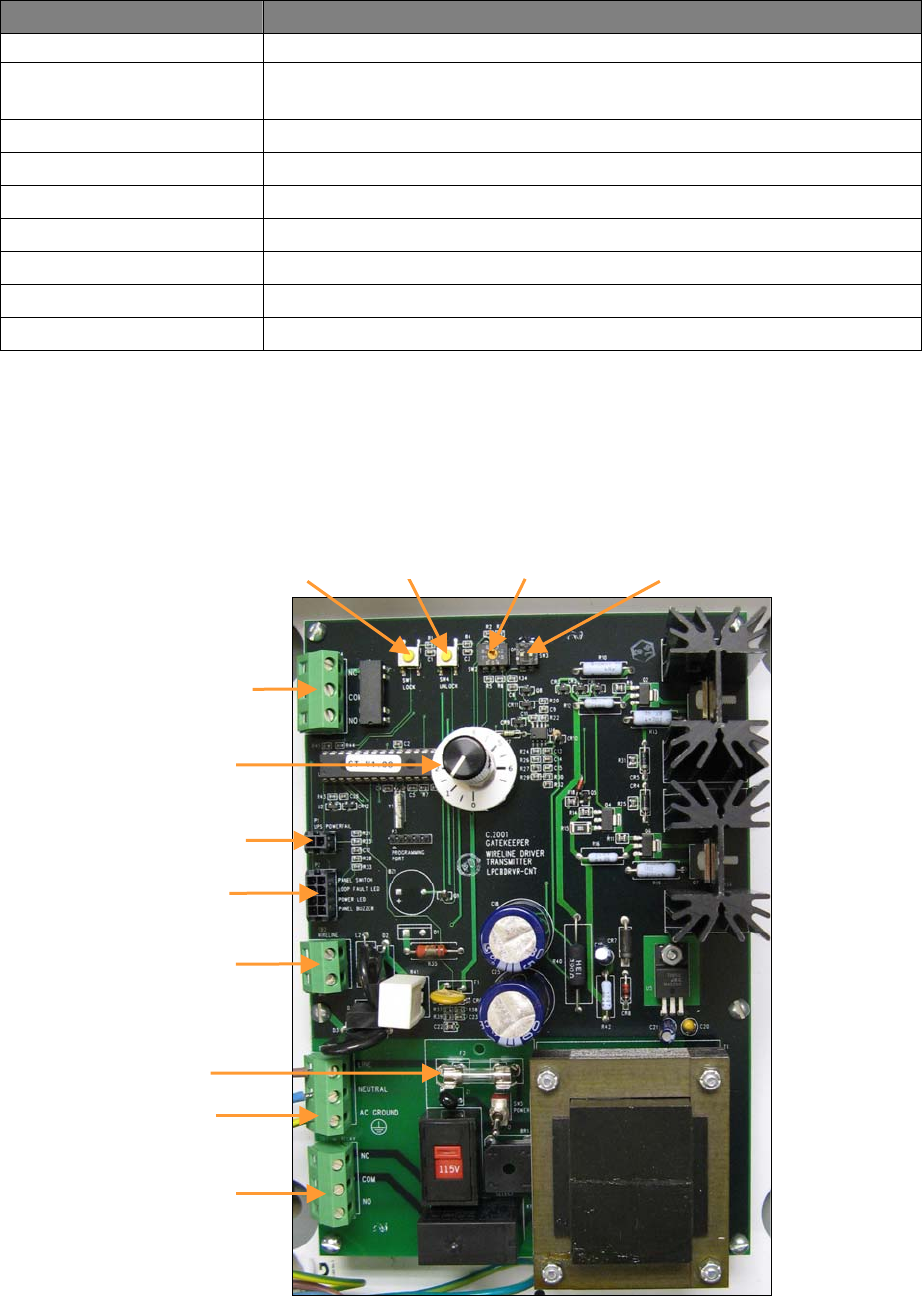
CentralTransmitter Circuit Board
Actual Layout
Detailed photo of the GS2 CT circuit board. Note that the actual placement of components may vary slightly with
different versions of the board.
Antenna Alert
Relay
Connectors
Power Alert
Relay
Connectors
UPS Power
Backup
Front Panel
Connectors
Perimeter Antenna
Connectors
Power
Connectors
Signal Strength
Adjustment
Fuse
SW3 Lock Rotary
Selector
Mode Selector
Switch
SW4
Unlock
Installation
GATEKEEPER SYSTEMS INC.
2007 CART CONTAINMENT MANUAL
Page 28
Installation
GATEKEEPER SYSTEMS INC.
2007 CART CONTAINMENT MANUAL
Page 29
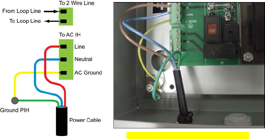
Connecting Electrical Power to the CentralTransmitter
The CentralTransmitter may be powered using the power cord included, or by hard wiring the unit to an available
circuit. The circuit for the power outlet must be equipped with a 15 Amp circuit breaker. The Transmitter does not
require a designated circuit, but the circuit must have 24-hour power supply available. The circuit must be a non-
switched circuit. Use the voltage selector to set the proper voltage. Do not turn on any power to the transmitter
until instructed to do so in this manual.
The incoming power is terminated at TB1 AC. Terminate one wire to each of the Line Terminals. The ground wire
should to be green and yellow striped and should be connected to the ground screw located on the backboard
before getting connected to the ground connector of the power terminal. Do NOT power up yet!
Connecting the Central Transmitter power cable
NOTE: The CentralTransmitter should be connected to an Uninterruptible Power Supply (UPS) or hard wired to a
24-hour power source. Extension cords are NOT to be used. All connections must be in compliance with local
building codes.

Installation
GATEKEEPER SYSTEMS INC.
2007 CART CONTAINMENT MANUAL
Page 30
Calibrating the Central Transmitter
The CentralTransmitter board is an electronic signal generator which transmits a digitally encoded signal through
the perimeter antenna. After the CentralTransmitter has been properly installed, the antenna is connected, and
electrical power has been installed, set up and testing of locking distance is required.
1. Turn the potentiometer to zero.
2. Set the “SW5 POWER” switch to ON.
3. Wait 10-15 seconds for the transmitter to energize, then turn the potentiometer to “2.5”. This should result in
a locking distance of approximately three (3) feet from the perimeter antenna.
4. Go outside and test the locking range of a GS2 Wheel. It should begin to lock at approximately three (3) feet
from the perimeter antenna.
5. Continue checking different points of the perimeter to insure that all locking points have a consistent locking
range. Confirm that all areas are protected with a locking range of approximately three (3) feet on either side
of the perimeter antenna.
Remember, each time a wheel is unlocked it will be unable to lock again for 10-15 seconds. There is a delay
programmed into the wheel, to allow a wheel to be removed from the influence of the locking zone, after it is
unlocked. If twisted pair has been installed, verify that there are no gaps in protection between the edge of the
twisted pair and the locking loop. In addition, verify that the twisted pair is not emitting a locking signal, which
locks the GS2 Wheel.
Confirm that the wheel will not lock anywhere inside of the store. Check all entranceways, checkout lanes, and
cart corrals.
Selecting the Transmitter Mode
The D-9110A CentralTransmitter may be configured to send out four different types of signals. The four types are
Digital (GS2 and GS1), Analog, EP2000, and Door Mode.
Inside the transmitter, the mode selector switch location is SW3. To change from one mode to another, first turn
off the transmitter, then switch SW3 to the desired mode before powering on the transmitter again. The switch
values and their corresponding signals are shown below:
SW3 Setting SIGNAL TYPE
00 (Both Off) GS2 Digital Signal
01 Gatekeeper Analog Signal
10 EP2000 Signal
11 (Both On) Door Mode Signal
The Gatekeeper Digital Signal will work with any digital version of Gatekeeper wheel (GS1, GS1.1, and GS2). The
Gatekeeper Analog Signal will work only with a Gatekeeper Analog wheel. The EP2000 Signal will work with a
GS2 Wheel, Gatekeeper EP2000 wheel, and Carttronics CAPS caster. The Door Mode Signal is the same signal
as the ExitManager Door Signal, and is used only when the D-9110 CentralTransmitter is used in an
ExitManager configuration.
Installation
GATEKEEPER SYSTEMS INC.
2007 CART CONTAINMENT MANUAL
Page 31
Connecting the Alarm Relays
The CentralTransmitter Alert Relays provide the capability of forwarding CT status alerts to an existing store
monitoring or security system. There are two alert relay circuits built in to the GS2 board:
• Power Alert Relay – outputs a signal from the Power Alert Relay connectors in the event of a power
outage to the CT.
• Antenna Alert Relay – outputs a signal from the Antenna Alert Relay connectors if the
CentralTransmitter stops receiving the terminating signal from the Perimeter Antenna.
To enable these alert relay features, the store’s Alarm Service Provider should connect the leads from the
appropriate store system to the Power Alert Relay connectors and/or the Antenna Alert Relay connectors, as
shown on the circuit board diagram, 27.
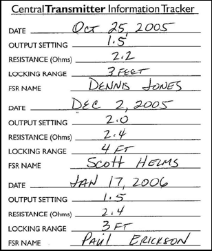
Information Tracker
Upon completion of the Central Transmitter installation,
make a note to indicate the Date, Line Resistance (from
your ohm meter), Locking Range, and technician Name in
the Central Transmitter Information Tracker. This should
be checked and updated on each successive service visit
to the store.
Information tracker with initial entry and two
subsequent service entries.
Installation
GATEKEEPER SYSTEMS INC.
2007 CART CONTAINMENT MANUAL
Page 32
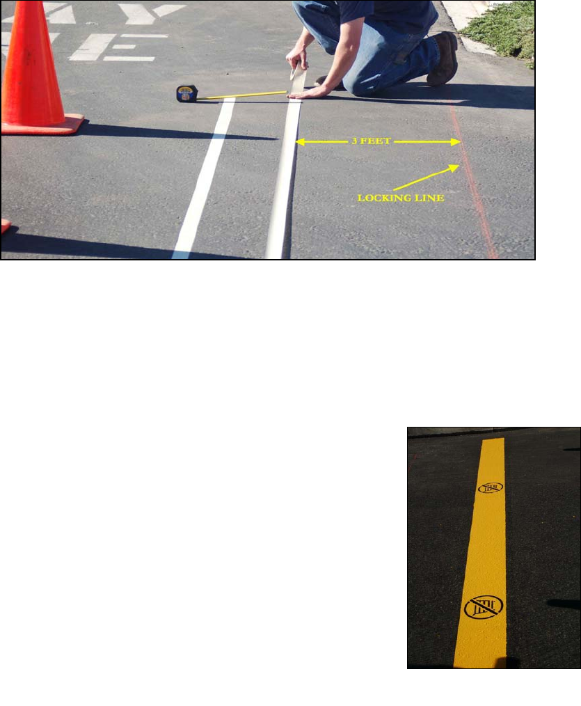
Finished Perimeter Stripe
Perimeter Striping
You will need:
• Masking Tape,
• Nine (9”) inch paint roller ¾” nap for medium rough surfaces,
• Gliden Ultra-Hide Durus Acrylic Traffic Paint (Lot# GL-0087,
• Thermoplastic striping tape (for wet conditions only).
Measuring for the perimeter stripe
Striping the containment area is an important part of the installation. Perimeter striping works in combination with
parking lot signs and cart-mounted signs to educate and warn the customer of the new limits of cart travel. It is
important that the striping is bright, clean, and straight.
Stripe any area along the antenna perimeter where carts may exit, including: major ingress/egress points such
as drive ways, walkways exiting the property, and major drive lanes within the parking lot. Do not stripe areas
where the perimeter antenna runs along walls, fences, or landscaping.
The perimeter stripe should be located approximately three feet (3’) before the
antenna path, as this is where the Gatekeeper wheel will begin to lock. The
stripe should be nine inches (9”) wide.
Thoroughly sweep the area clean of any debris prior to placing chalk lines and
masking tape. It is helpful to section off the area using traffic cones or caution
tape. Use chalk lines and masking tape to mark the area to be striped. Prior to
painting, insure that the masking tape is straight and that there is no debris
inside the edges of the tape. Debris will cause the paint to flow outside the
edges of the tape and create smudges. Using a nine (9) inch semi-rough paint
roller, apply a coat of yellow traffic paint inside the masked area. In most
cases, two coats will be required. After the stripe has been painted, remove the
masking tape immediately. Allow 20 minutes for the paint to dry before any
traffic crosses the newly applied stripe (you may also dry with a torch).
After the paint has dried, a stencil is applied on top of the perimeter striping.
The stencil is placed directly over the striping and sprayed with BLACK spray
paint. A good rule of thumb is to place a stencil for every five (5) feet of
striping.
Installation
GATEKEEPER SYSTEMS INC.
2007 CART CONTAINMENT MANUAL
Page 33
Thermoplastic striping
In the event that weather conditions do not allow the application of paint, a Thermoplastic stripe may be applied.
These stripes typically come in 3’ x 4” sections and are applied to the asphalt using a blow torch. If the asphalt is
wet, it must first be dried using the blow torch. Once the asphalt is dry, the Thermoplastic stripe should be placed
and then heated with the torch until it completely adheres to the asphalt.
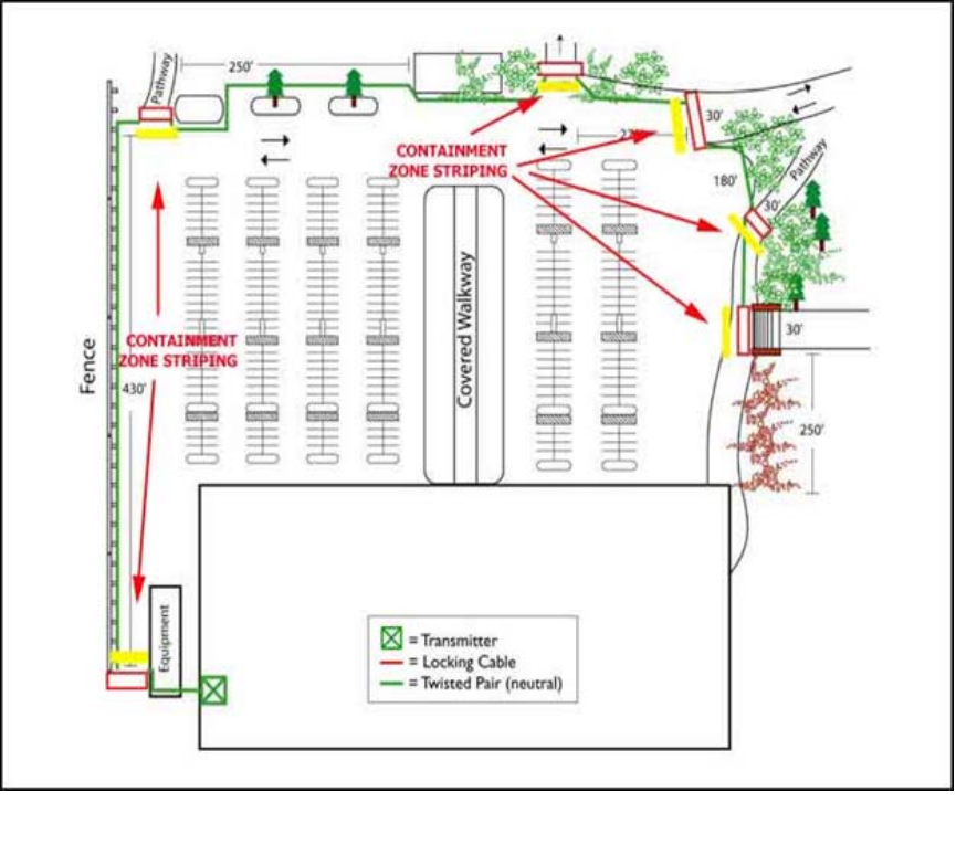
Sample Striping Layout Map
Striping locations are indicated on each of the “Sample Site Plans” in addition to the diagram below.
Site plan showing striping areas
Installation
GATEKEEPER SYSTEMS INC.
2007 CART CONTAINMENT MANUAL
Page 34
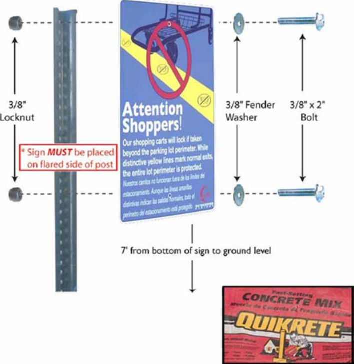
Installing the Parking lot Signs
Parking lot signs work in combination with the containment zone striping to educate shoppers as to the location
of the system perimeter. Signs should be installed at locations where carts are most likely to be taken from the
parking lot. Make sure that all ingress/egress points (driveways) have a minimum of one sign. Additional signs
may be placed on existing lamp posts or sign posts, using sign straps. If no existing posts are available or
located in logical locations for a parking lot sign, you will need to install a parking lot sign along with a sign post
(instructions to follow). Parking lot signs should be installed no less the seven feet (7’) from the bottom of the
sign to ground level. Do not install any sign that may cause a hazard to pedestrians. Do not mount signs on a
public street light, traffic signal pole, or any property not managed/owned by the store.
When installing the parking lot sign and sign post, the sign post should be buried no less than two feet (2’) into
the landscaping and the post should be placed in Quikrete or a comparable concrete mixture in order to ensure a
solid base that will withstand high winds and tampering. The sign should only be installed on the flared side of
the sign post, with a 3/8” fender washer placed between the bolt head and the sign.
For more details on installing the parking lot signs, see page 51.
Parking lot sign assembly
Installation
GATEKEEPER SYSTEMS INC.
2007 CART CONTAINMENT MANUAL
Page 35
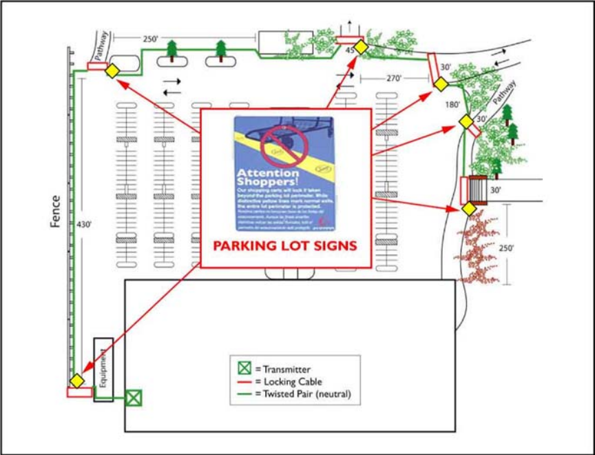
Sample Parking Lot Sign Layouts
Parking log sign detail on site map
Installation
GATEKEEPER SYSTEMS INC.
2007 CART CONTAINMENT MANUAL
Page 36
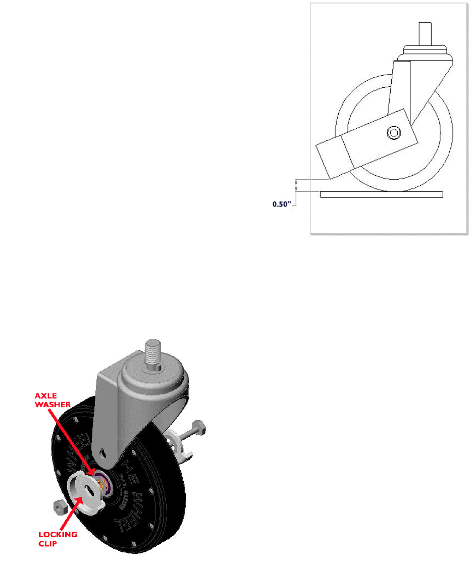
Installing the Anti-tilt Bars
The anti tilt bars must be tack welded BEFORE installation
of the GS2 Wheel. The GS2 Wheel contains sensitive
electronic parts that can be damaged.
The anti- tilt bar is mounted on the right rear horn as you
push the cart. This must be a rigid non-swivel horn. If your
carts have four swivel casters, do NOT use an anti-tilt bar.
The GS2 Wheel will be mounted on the opposite front
caster from the anti-tilt bar.
Place the anti-tilt bar on the wheel horn, align the holes
over wheel axel rivets, and clamp into place. This is done
with a “C-Clamp” or a pair of “Vice-Grip” clamps. Adjust the
anti-tilt bar to one-half inch (½“) from the asphalt. Once the
anti-tilt bar is clamped in place, you will tack-weld the bar to
the horn (tack-welds should be placed on both sides of the
anti-tilt bar). If the cart is “Powder Coated”, you will need to
grind the welding area before you weld so that the weld
penetrates the metal on both the horn and anti-tilt bar.
Once the weld is complete, remove the clamp and wire
brush both sides. Apply a quick spray of paint on the welds
and any areas affected by the grinding to keep rust from
forming on the cart.
Installing the GS2 Wheel
The GS2 wheel is pre-assembled on an industry-standard swivel caster and will be a direct replacement for one
of the two front factory installed swivel casters (typically the left front).
Remove the original caster by removing the caster nut from
the top side of the caster plate.. Once the factory installed
caster is removed, replace it with the GS2 Wheel assembly.
Care should be taken not to over tighten the caster bolt,
which would prevent the caster from swiveling. Before
applying the lock nut to the caster bolt, Locktite should be
applied to the caster bolt.
If the GS2 Wheel is not assembled to a swivel caster, you
may mount the wheel to a caster using the parts contained in
a Field Installation Kit. This kit includes: two (2) locking clips,
one (1) axle bolt, one (1) axle nut, and two (2) axle washers.
All shipments of GS2 Wheels, without swivel casters will
contain a Field Installation Kit. To install, first place the
washers over the axle and onto the bearings, next place the
locking clips over the washers and onto the portion of the axle
that extends out of the bearings. Slide the bolt through the
axle, apply Locktite2 to the axle bolt, and tighten the lock nut.
Take care not to over tighten the axle nut, preventing the
wheel from rotating.
Placement of the anti-tilt bars
Installation
GATEKEEPER SYSTEMS INC.
2007 CART CONTAINMENT MANUAL
Page 37
Installing the Cart-Mounted Signs
Each shopping cart containing a GS2 Wheel shall have a Cart-Mounted Sign Kit installed on it. If not installed by
the cart manufacturer, the Cart-Mounted Sign kits will be shipped to the store by Gatekeeper Systems.
Each sign kit will contain:
• two (2) black, rectangular frames, one of which will have a vinyl sticker with the warning language,
• four (4) screws.
For example, you will need 400 black plastic frames and 800 screws to install sign kits on 200 carts.
Tools required:
• Cordless screw driver, such as a Mikita cordless drill
• Phillips head screw driver tip (magnetic head helpful)
• Gatekeeper part number M-1210 (#8, ¾”, phillips head screw)
1. Sandwich together the two frames (they are all identical and have matching male/female posts) around the
wire of the front portion of the cart. Be sure that the warning language on the sign will face the customer, as
they push the cart.
2. Press the two frames together until you hear the snapping noise of the posts securely fastening to each
other.
3. Screw four (4) screws into the large opening on the Cart-Mounted Sign: two (2) screws on the inside of the
cart and two (2) screws on the outside of the cart.
Installation Photographs
GATEKEEPER SYSTEMS INC.
2007 CART CONTAINMENT MANUAL
Page 38
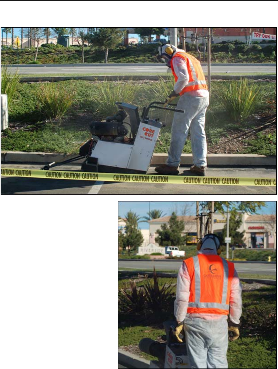
5 Installation Photographs
Always use Caution Tape to mark off the work area. Wear proper safety gear when operating the concrete saw.
Safety gear includes a full face respirator, ear protection, and a full-body suit.
A Gatekeeper fluorescent-orange safety vest
should be worn at all times.

Installation Photographs
GATEKEEPER SYSTEMS INC.
2007 CART CONTAINMENT MANUAL
Page 39
A self-propelled concrete saw such as the
Core Cut shown below is used for cutting the
asphalt.
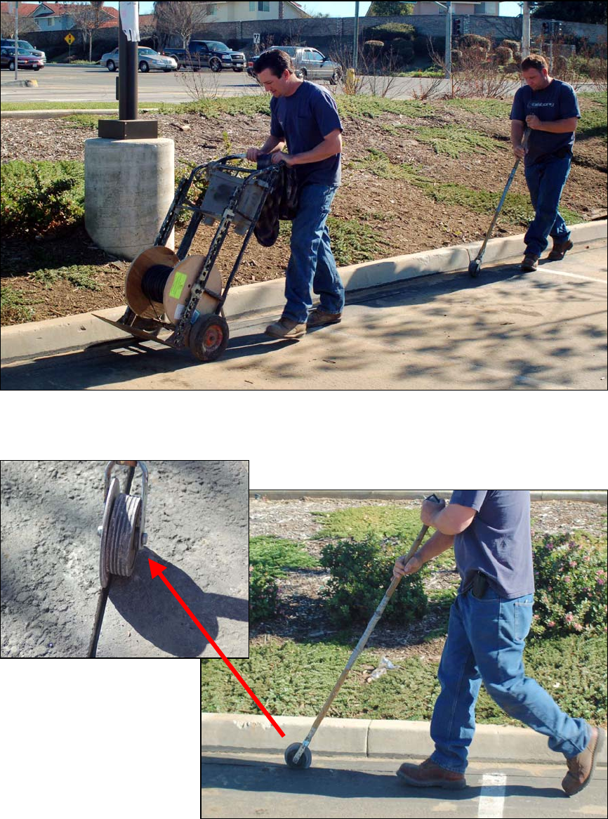
The saw cut may be cleaned using the
Gatekeeper Hook. Insert the hook into the
saw cut and drag it, to clean out asphalt
debris.
Use the Kleen Sweep 27 push sweeper to
clean up excess asphalt debris once the line
has been saw-cut.
Installation Photographs
GATEKEEPER SYSTEMS INC.
2007 CART CONTAINMENT MANUAL
Page 40
Laying the Antenna Wire
Use a wire caddy to roll out the 14AWG antenna along the saw cut.
A crew member may then insert the antenna into the saw cut, using the Gatekeeper Antenna Roller.
Installation Photographs
GATEKEEPER SYSTEMS INC.
2007 CART CONTAINMENT MANUAL
Page 41
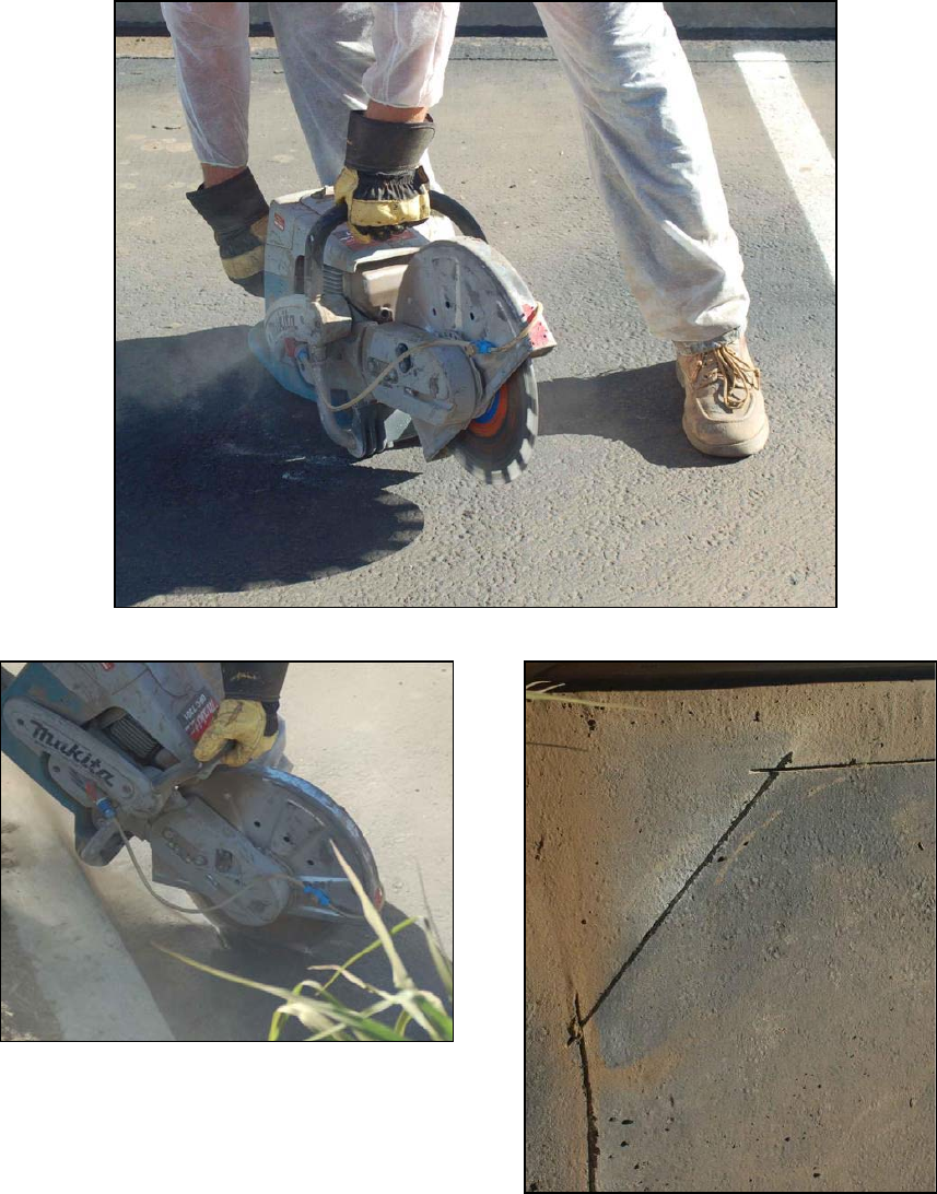
Sawing Corners
When cutting in a corner, where the antenna changes direction, use a gas powered hand saw to cut a 45-degree
angle.
A 45-degree angle (above right) is required for all
corners, as a sharp bend in the antenna may cause the
locking signal to be projected in an abnormal manner
Installation Photographs
GATEKEEPER SYSTEMS INC.
2007 CART CONTAINMENT MANUAL
Page 42
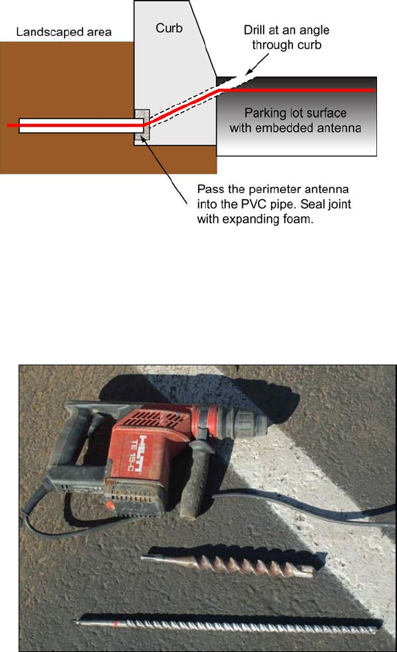
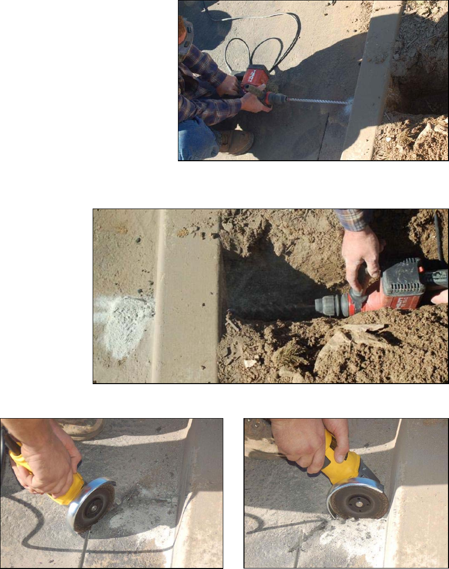
Perimeter Antenna through Curbs
In some installations it is
necessary to transition from the
asphalt to a garden area. In these
instances, saw cut up to the curb
or island where the landscape
area begins. At the beginning of
the curb or transition, use a roto-
hammer to drill a hole from the
end of the saw cut through the
curb, down into the landscape
area. The path of the drill should
be at a 45º downward angle. Pass
the antenna from the saw cut,
through the curb, and into the
landscape area. Once in the
landscape area, route the antenna
wire inside schedule 40 PVC
conduit. The conduit should be
buried a minimum of 6” – 8”
inches in depth.
You will need a smaller diameter
bit for the pilot hole and a 1 inch
bit to enlarge the bore to
accommodate the PVC pipe.
Installation Photographs
GATEKEEPER SYSTEMS INC.
2007 CART CONTAINMENT MANUAL
Page 43
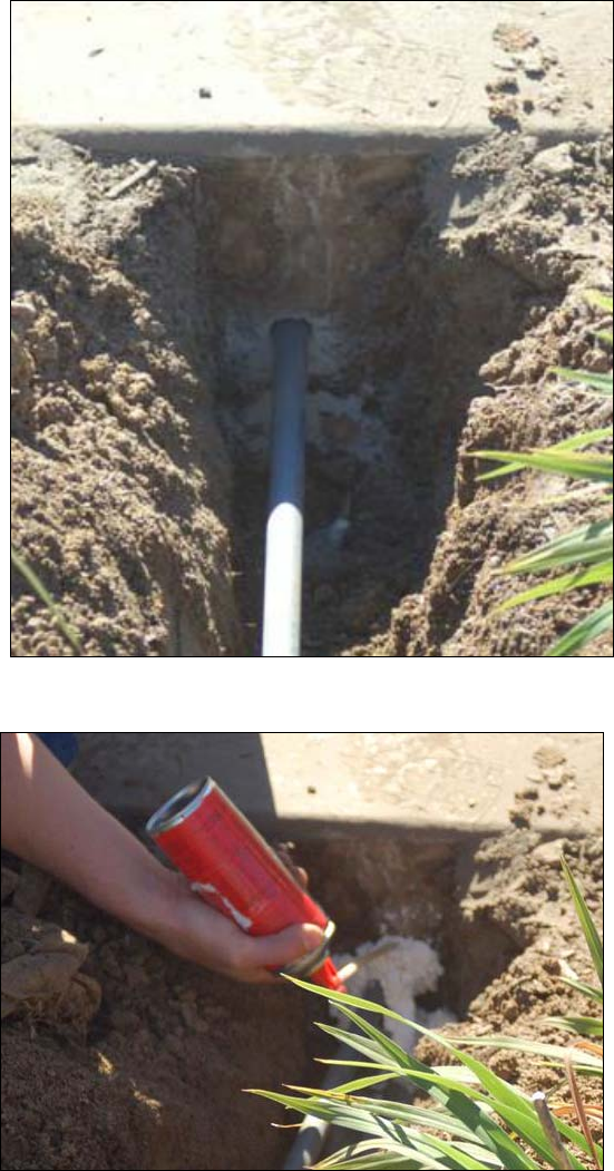
First create a trench in the
landscaping area and then drill
through the curb using the roto-
hammer drill
Using the roto-hammer, drill through the curb into the landscape area and then back from the landscape area
towards the asphalt. After the pilot hole is through, use a one-inch (1”) bit to ream out the inside of the bore to
accommodate the PVC pipe.
Make the saw cuts in the asphalt near the curb using a 4 1/2 inch (or larger) angle grinder.
Installation Photographs
GATEKEEPER SYSTEMS INC.
2007 CART CONTAINMENT MANUAL
Page 44
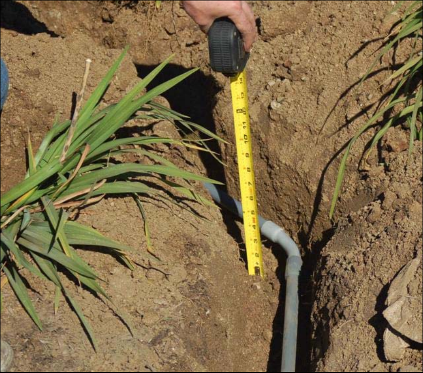
PVC conduit is then used to protect the
antenna when it runs through the
landscaping area
The end of the conduit is placed into the
hole that was drilled through the curb line
and expansion foam is used to seal the
area where the conduit enters the curb.
Installation Photographs
GATEKEEPER SYSTEMS INC.
2007 CART CONTAINMENT MANUAL
Page 45
Conduit should always be buried six to eight inches (6-8”) below the surface of the landscaping.
Installation Photographs
GATEKEEPER SYSTEMS INC.
2007 CART CONTAINMENT MANUAL
Page 46
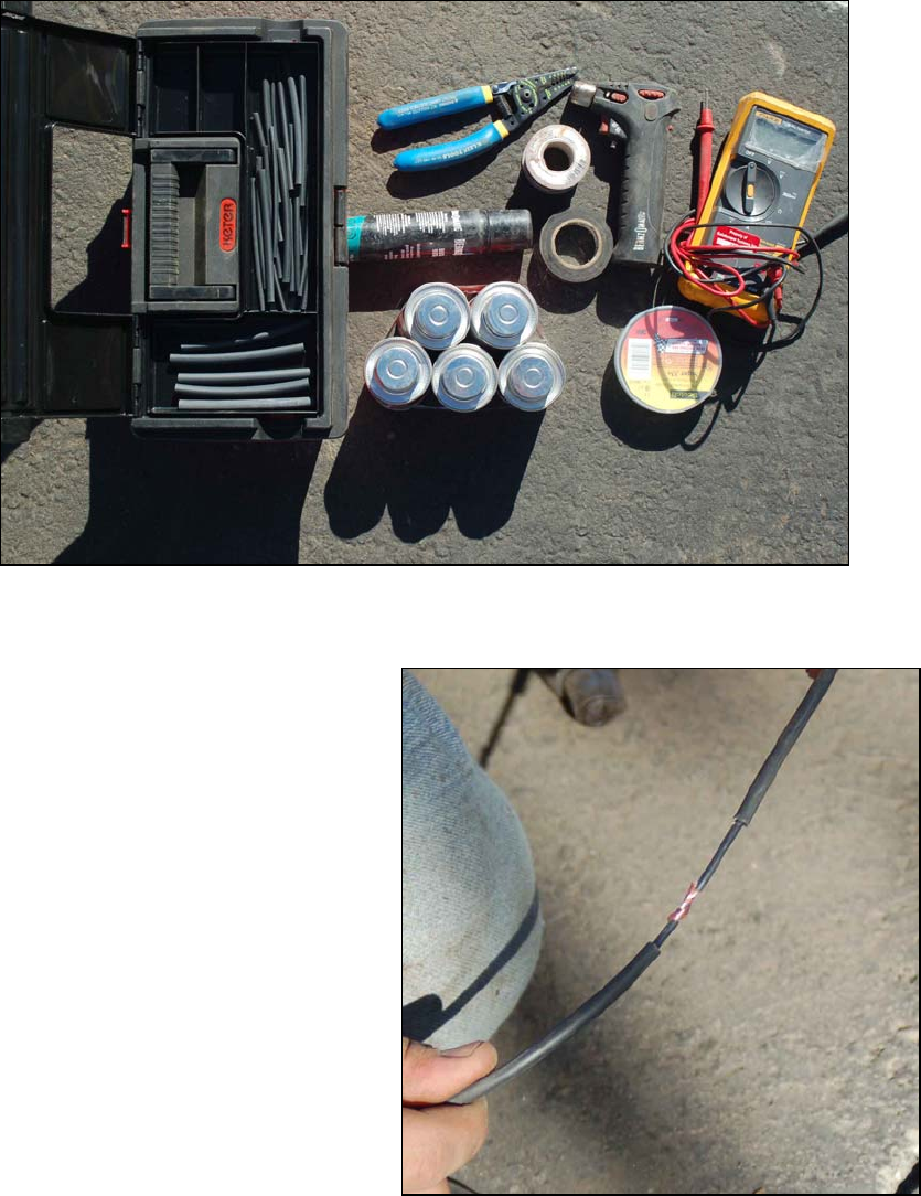
Splicing the Perimeter Antenna
As the antenna is rolled out and inserted into the saw-cut, it will be necessary to splice together sections of
antenna. This job will go faster if you put together a splicing kit like the one shown below.
A sample splicing kit
Forming the splice:
1. Strip off approximately two inches of the
outside insulation from each side of the splice.
2. Strip off the inner insulation to expose about 1
inch of copper wire on each side of the splice.
3. Slide a piece of heat shrink tubing about 5
inches long onto one of the wires. Move it
away from the splice for now.
4. Twist the strands together as shown in the
figure at right, keeping the two wires in line
with each other. DO NOT bend the wire at a
90 degree angle to form the splice.