Gateway Alr 9200 Users Manual Server
ALR 9200 to the manual fdf05998-94a7-43e0-860f-6de2e50cf6ff
2015-02-02
: Gateway Gateway-Alr-9200-Users-Manual-403176 gateway-alr-9200-users-manual-403176 gateway pdf
Open the PDF directly: View PDF ![]() .
.
Page Count: 226 [warning: Documents this large are best viewed by clicking the View PDF Link!]
- Contents
- Preface
- System Access
- Components
- Installing Components
- Jumpers and Drivers
- BIOS Setup
- The Server Setup Utility
- Other Utilities
- Introduction
- Power-on Self Test
- Emergency Management Port Console
- FRU and SDR Load Utility
- Using the Firmware Update Utility
- Using the Symbios SCSI Utility
- Troubleshooting
- Introduction
- Computer Virus Notice
- Troubleshooting Checklist
- Solving Problems
- Resetting the System
- Initial System Startup
- Running New Application Software
- The System Has Been Running Correctly
- More Problem-solving Procedures
- Specific Problems and Corrective Actions
- Power Light Does Not Light
- No Beep Codes
- No Characters Appear on Screen
- Characters Are Distorted or Incorrect
- System Cooling Fans Do Not Rotate Properly
- Diskette Drive Activity Light Does Not Light
- Hard Disk Drive Activity Light Does Not Light
- CD-ROM Drive Activity Light Does Not Light
- Network Problems
- PCI Installation Tips
- Problems with Application Software
- Bootable CD-ROM Is Not Detected
- Error and Informational Messages
- Reference Data
- Regulatory Compliance Statements
- Index

Maintaining and
Troubleshooting
the Gateway
ALR 9200 Server
Part # 8503424 A MAN SYS US 9200 TECH REF R0 8/98
In our effort to use nature’s resources efficiently and wisely, we print all manuals on recycled papers that meet the
minimum requirements established by the Federal EPA in its guidelines for recycled paper products.
3424.boo Page i Wednesday, September 2, 1998 9:23 AM

Notices
Copyright © 1998 Gateway 2000, Inc.
All Rights Reserved
610 Gateway Drive
N. Sioux City, SD 57049 USA
All Rights Reserved
This publication is protected by copyright and all rights are reserved. No part of it may be reproduced or
transmitted by any means or in any form, without prior consent in writing from Gateway 2000.
The information in this manual has been carefully checked and is believed to be accurate. However,
changes are made periodically. These changes are incorporated in newer publication editions. Gateway
2000 may improve and/or change products described in this publication at any time. Due to continuing
system improvements, Gateway 2000 is not responsible for inaccurate information which may appear in
this manual. For the latest product updates, consult the Gateway 2000 web site at www.gateway.com. In
no event will Gateway 2000 be liable for direct, indirect, special, exemplary, incidental, or consequential
damages resulting from any defect or omission in this manual, even if advised of the possibility of such
damages.
In the interest of continued product development, Gateway 2000 reserves the right to make
improvements in this manual and the products it describes at any time, without notices or obligation.
Trademark Acknowledgments
AnyKey, black-and-white spot design, CrystalScan, Destination, EZ Pad, EZ Point, Field Mouse, Solo,
TelePath, Vivitron, stylized “G” design, and “You’ve got a friend in the business” slogan are registered
trademarks and GATEWAY, Gateway Solo, green stylized GATEWAY, green stylized Gateway logo, and
the black-and-white spotted box logo are trademarks of Gateway 2000, Inc. Intel, Intel Inside logo, and
Pentium are registered trademarks and MMX is a trademark of Intel Corporation. Microsoft, MS, MS-DOS,
and Windows are trademarks or registered trademarks of Microsoft Corporation. All other product names
mentioned herein are used for identification purposes only, and may be the trademarks or registered
trademarks of their respective companies.
Copyright © 1998 Advanced Logic Research, Inc. (ALR)
All Rights Reserved
9401 Jeronimo
Irvine, CA 92618 USA
All Rights Reserved
This publication is protected by copyright and all rights are reserved. No part of it may be reproduced or
transmitted by any means or in any form, without prior consent in writing from ALR.
The information in this manual has been carefully checked and is believed to be accurate. However,
changes are made periodically. These changes are incorporated in newer publication editions. ALR may
improve and/or change products described in this publication at any time. Due to continuing system
improvements, ALR is not responsible for inaccurate information which may appear in this manual. For the
latest product updates, consult the ALR web site at www.alr.com. In no event will ALR be liable for direct,
indirect, special, exemplary, incidental, or consequential damages resulting from any defect or omission in
this manual, even if advised of the possibility of such damages.
In the interest of continued product development, ALR reserves the right to make improvements in this
manual and the products it describes at any time, without notices or obligation.
Trademark Acknowledgments
ALR is a registered trademark of Advanced Logic Research, Inc. All other product names mentioned
herein are used for identification purposes only, and may be the trademarks or registered trademarks of
their respective companies.
Some portions of this document are copyright © 1998, Intel Corporation.
3424.boo Page ii Wednesday, September 2, 1998 9:23 AM

Contents i
Contents
Preface .....................................................................................vii
About This Guide................................................................................ viii
Conventions Used in This Guide........................................................... ix
Important Safety Instructions.................................................................. x
Chapter 1: System Access ....................................................... 1
Static Electricity Precautions .................................................................. 2
Opening the System ................................................................................ 3
Removing the Access Cover............................................................ 3
Opening the Front Door................................................................... 4
Opening the Subchassis and Electronics Bay ................................. 5
Closing the System.................................................................................. 7
Closing the Subchassis and Electronics Bay................................... 7
Installing the Access Cover.............................................................. 8
Installing the Front Door.................................................................. 8
Chapter 2: Components ........................................................... 9
System Board Features.......................................................................... 10
System Board Connectors..................................................................... 10
Drive Controllers and Connectors................................................. 12
System Jumpers (B) ....................................................................... 13
Miscellaneous Connectors............................................................. 14
Expansion Slot Connectors............................................................ 15
Memory Module Connector (I) ..................................................... 16
System Management Connectors.................................................. 16
Back Panel I/O Connectors............................................................ 18
Processors and Related Connectors............................................... 20
Power Connectors .......................................................................... 21
Memory.................................................................................................. 23
DIMM Installation Sequence......................................................... 24
System Memory Addressing ......................................................... 24
Memory Configuration.................................................................. 25
System Security..................................................................................... 26
Mechanical Locks and Monitoring................................................ 26
Software Locks via the SSU or BIOS Setup................................. 26
3424.boo Page i Wednesday, September 2, 1998 9:23 AM

ii Maintaining and Troubleshooting the Gateway ALR 9200 Server
Chapter 3: Installing Components ...........................................31
Introduction........................................................................................... 32
Replacing the Processor........................................................................ 32
Installing Another Processor ................................................................ 36
Installing Hardware............................................................................... 40
Memory.......................................................................................... 40
Drives ............................................................................................. 45
Installing Fans for High-Power Drives......................................... 57
Expansion Cards............................................................................ 62
Power Supplies .............................................................................. 65
Replacing the Battery .................................................................... 68
Chapter 4: Jumpers and Drivers .............................................71
Setting the Jumpers............................................................................... 72
Changing a Jumper Setting............................................................ 73
CMOS Clear Jumper ..................................................................... 74
Password Clear Jumper ................................................................. 75
Recovery Boot Jumper.................................................................. 75
Installing Software and Drivers............................................................ 77
Installing Video Drivers ................................................................ 77
Chapter 5: BIOS Setup ...........................................................79
Introduction........................................................................................... 80
Using BIOS Setup................................................................................. 81
Record Your Setup Settings.......................................................... 81
If You Cannot Access Setup ......................................................... 82
Starting Setup................................................................................. 82
Setup Menus.......................................................................................... 83
Setup Key Commands................................................................... 84
Special Display Items .................................................................... 84
Main Menu..................................................................................... 85
Advanced Menu............................................................................. 87
Security Menu................................................................................ 92
Server Menu................................................................................... 93
Boot Menu...................................................................................... 95
Exit Menu....................................................................................... 97
3424.boo Page ii Wednesday, September 2, 1998 9:23 AM

Contents iii
Upgrading the BIOS.............................................................................. 98
Preparing for the Upgrade.............................................................. 98
Upgrading the BIOS..................................................................... 100
Recovering the BIOS ................................................................... 101
Changing the BIOS Language..................................................... 101
Chapter 6: The Server Setup Utility .......................................103
Introduction.......................................................................................... 104
Using the System Setup Utility........................................................... 105
When to Run the SSU .................................................................. 105
What You Need to Do.................................................................. 106
Running the SSU................................................................................. 107
Running the SSU Locally ............................................................ 107
Running the SSU Remotely......................................................... 107
Starting the SSU........................................................................... 108
Customizing the SSU.......................................................................... 109
Launching a Task ................................................................................ 111
Resource Configuration Add-in Window .......................................... 112
Using the RCA Window.............................................................. 112
Defining an ISA Board................................................................. 113
Adding and Removing ISA Boards............................................. 114
Modifying Resources................................................................... 114
System Resource Usage............................................................... 115
Multiboot Options Add-in................................................................... 115
Security Add-in ................................................................................... 116
Security Options........................................................................... 117
System Event Log Viewer Add-in...................................................... 118
Sensor Data Record Manager
Add-In.................................................................................................. 120
Field Replaceable Unit Manager Add-In ........................................... 122
Exiting the SSU................................................................................... 124
Chapter 7: Other Utilities .......................................................125
Introduction.......................................................................................... 126
Power-on Self Test.............................................................................. 127
Emergency Management Port Console.............................................. 129
How the EMP Console Works..................................................... 130
EMP Console Requirements........................................................ 132
3424.boo Page iii Wednesday, September 2, 1998 9:23 AM

iv Maintaining and Troubleshooting the Gateway ALR 9200 Server
Setting Up the Server for the EMP.............................................. 133
Main EMP Console Window...................................................... 134
Server Control Operations........................................................... 136
Phonebook.................................................................................... 140
Management Plug-ins.................................................................. 141
FRU and SDR Load Utility................................................................ 145
When to Run the FRUSDR Load Utility.................................... 145
What You Need to Do ................................................................. 145
How You Use the FRUSDR Load Utility .................................. 146
Cleaning Up and Exiting ............................................................. 150
Using the Firmware Update Utility.................................................... 151
Running the Firmware Update Utility ........................................ 151
Using the Symbios SCSI Utility......................................................... 152
Running the SCSI Utility............................................................. 152
Chapter 8: Troubleshooting ..................................................153
Introduction......................................................................................... 154
Computer Virus Notice....................................................................... 155
Viruses.......................................................................................... 155
Types of Viruses.......................................................................... 155
Virus Contamination.................................................................... 155
Protecting Your System............................................................... 156
Virus Prevention.......................................................................... 156
Troubleshooting Checklist ................................................................. 158
Verifying the Configuration........................................................ 158
Troubleshooting Guidelines........................................................ 158
Solving Problems................................................................................ 159
Resetting the System.................................................................... 159
Initial System Startup................................................................... 159
Running New Application Software........................................... 160
The System Has Been Running Correctly.................................. 161
More Problem-solving Procedures ............................................. 162
Specific Problems and Corrective Actions................................. 164
Error and Informational Messages..................................................... 170
POST Codes and Countdown Codes.......................................... 170
POST Error Codes and Messages............................................... 173
3424.boo Page iv Wednesday, September 2, 1998 9:23 AM

Contents v
Appendix A: Reference Data ................................................ 175
Specifications....................................................................................... 176
System Specifications.................................................................. 176
Environmental Specifications...................................................... 177
System I/O Addresses ......................................................................... 178
Memory Map....................................................................................... 181
Interrupts.............................................................................................. 182
Video Modes ....................................................................................... 183
DMA Usage......................................................................................... 187
Appendix B: Regulatory Compliance Statements ................ 189
Electromagnetic Compatibility........................................................... 190
FCC Notice.......................................................................................... 191
Industry Canada Notice....................................................................... 192
CE Notice............................................................................................. 192
VCCI Notice........................................................................................ 193
Australia/New Zealand Notice ........................................................... 193
Declaration of the Manufacturer or Importer..................................... 194
Safety Compliance .............................................................................. 194
Index .....................................................................................195
3424.boo Page v Wednesday, September 2, 1998 9:23 AM

vi Maintaining and Troubleshooting the Gateway ALR 9200 Server
3424.boo Page vi Wednesday, September 2, 1998 9:23 AM


viii Maintaining and Troubleshooting the Gateway ALR 9200 Server
About This Guide
This document provides step-by-step installation instructions along with
detailed illustrations to help maintain the hardware components and
peripherals of the computer.
Chapter 1: System Access provides instructions on opening and closing the
case.
Chapter 2: Components covers information on maintaining, replacing, and
upgrading the components in the system. This section includes information
about options for the system and installation instructions.
Chapter 3: Installing Components describes the procedures for installing or
replacing the hardware components.
Chapter 4: Jumpers and Drivers describes setting the jumpers and provides
basic information about operating systems and software.
Chapter 5: BIOS Setup briefly explains the system basic input/output
system (BIOS) and provides instructions on how to update the BIOS.
Chapter 6: The Server Setup Utility describes the system setup utility and
provides instructions on using it to set up the server.
Chapter 7: Other Utilities describes the other utilities provided with the
system and provides instructions for their use.
Chapter 8: Troubleshooting provides reference material on troubleshooting
your system.
3424.boo Page viii Wednesday, September 2, 1998 9:23 AM
Conventions Used in This Guide ix
Conventions Used in This Guide
Throughout this document, you will see the following conventions:
Convention Description
ENTER Key names, which correspond to keys
on the keyboard, are printed in small
capitals.
CTRL+ALT+DEL A plus sign indicates that the keys
must be pressed simultaneously.
Setup Commands to be entered, options to
select, and messages that appear on
your monitor are printed in bold.
User’s Guide Names of publications and files are
printed in italic.
Sidebars Sidebars give critical information such
as warnings and important notes.
Note:
This is an example of an
important note that may
appear in the manual.
3424.boo Page ix Wednesday, September 2, 1998 9:23 AM

x Maintaining and Troubleshooting the Gateway ALR 9200 Server
Important Safety Instructions
Observe the following guidelines when performing any work on your
system:
•Follow all instructions marked on the server and in the
documentation.
•Unplug this product from the wall outlet before cleaning. Do not
use liquid or aerosol cleaners. Use a damp cloth for cleaning.
•Do not use this product near water. Do not spill liquid on or into the
server.
•Do not place the server on an unstable surface.
•Openings in the system cabinet are provided for ventilation. Do not
block or cover these openings. Do not place the server near or upon
a radiator or heat register.
•Use only the power source shown on the power supply. If you are
not certain about the power source, ask the local power company.
•The server is equipped with a 3-wire grounding plug (a plug with a
grounding pin). This plug only fits into a grounded power outlet.
This is a safety feature. If you are unable to insert the plug into the
outlet, contact your electrician to replace the outlet.
•Do not walk on the power cord or allow anything to rest on it.
•If you use an extension cord with this system, make sure the total
ampere ratings on the products plugged into the extension cord do
not exceed the extension cord ampere rating. Also, the total ampere
requirements for all products plugged into the wall outlet must not
exceed 15 amperes.
•Never insert objects of any kind into the system ventilation slots.
•Unplug the system from the wall outlet and refer servicing to
qualified personnel if:
• The power cord or plug is damaged.
• Liquid has been spilled into the system.
• The system does not operate properly when the operating
instructions are followed.
• The system was dropped or the cabinet is damaged.
• The system’s performance changes.
Warning!
Do not attempt to service
the system yourself except
as explained elsewhere in
the manual. Adjust only
those controls covered in
the instructions.
Opening or removing covers
marked “Do Not Remove”
may expose you to
dangerous voltages or other
risks.
Refer all servicing of those
compartments to qualified
service personnel.
Important!
The system power cord
serves as the main
disconnect for the
computer. The wall outlet
must be easily accessible by
the operator.
3424.boo Page x Wednesday, September 2, 1998 9:23 AM

Chapter 1:
System
Access
Contents
Static Electricity Precautions .................................. 2
Opening the System................................................. 3
Removing the Access Cover............................ 3
Opening the Front Door ................................... 4
Opening the Subchassis and Electronics Bay . 5
Closing the System.................................................. 7
Closing the Subchassis and Electronics Bay... 7
Installing the Access Cover.............................. 8
Installing the Front Door.................................. 8
3424.boo Page 1 Wednesday, September 2, 1998 9:23 AM

2 Maintaining and Troubleshooting the Gateway ALR 9200 Server
Static Electricity Precautions
Caution! Prevent Static-Electricity Damage
Static Electricity Preventions
1. WEAR A GROUNDING WRIST STRAP (available at most electronic stores).
2. Turn off the system power.
3. Touch the back of the power supply fan, located on the back of the case.
4. UNPLUG ALL CORDS FROM WALL OUTLET.
5. Remove the system case cover.
Static Electricity Precautions
♦Avoid static-causing surfaces such as plastic and styrofoam in your work area.
♦Remove the parts from their antistatic bags only when you are ready to use them. Do not lay
parts on the outside of antistatic bags since only the inside provides antistatic protection.
♦Always hold cards by their edges and their metal mounting bracket. Avoid touching
components on the cards and the edge connectors that connect to expansion slots.
♦Never slide cards or other parts over any surface.
3424.boo Page 2 Wednesday, September 2, 1998 9:23 AM

Opening the System 3
Opening the System
Depending on your purpose, you may need to remove the access cover or
both the access cover and the bezel. You may also need to open the
subchassis or the electronics bay to reach certain components. Follow the
instructions specific to the item you wish to remove or open as indicated in
each section.
Removing the Access Cover
You need to remove the system access cover to reach components inside the
system. Facing the front of the system, the access cover is on the right side
of the server.
1. Observe the ESD precautions in “Static Electricity Precautions” on
page 2.
2. Turn off all peripheral devices connected to the system.
3. Turn off the system by using the power on/off switch on the front panel
and unplugging all AC power cords.
4. Label and disconnect all peripheral cables attached to the input/output
(I/O) panel on the back of the system.
To Remove the Access Cover
Caution!
Power the system off and
disconnect all power cords
before proceeding. Installing
any component while the
power is on may cause
permanent damage to the
system.
3424.boo Page 3 Wednesday, September 2, 1998 9:23 AM
4 Maintaining and Troubleshooting the Gateway ALR 9200 Server
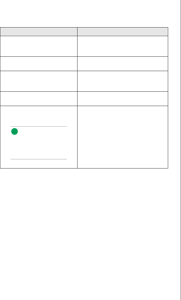
5. Remove and save the three screws from the back of the access cover
(see Figure 1); you will need them later to reattach the cover.
Figure 1: Removing the Access Cover
6. Place the fingertips of your right hand under the built-in handle on the
back of the cover. A rounded, rectangular depression in the front
middle of the access cover serves as another handle.
7. Using an even pull, slide the cover backward, about an inch, until it
stops.
8. Pull the entire cover outward, straight away from the chassis, to
disengage the rows of tabs from the notches in the top and bottom
edges of the chassis. Set the cover aside.
Opening the Front Door
The front door is secured to the bezel by a key lock. This lock has three
positions: fully locked, front door unlocked, and front and access cover
unlocked. When the front door is unlocked, you can remove it by opening it
fully and lifting the hinges out of the slots that hold them.
3424.boo Page 4 Wednesday, September 2, 1998 9:23 AM

Opening the System 5
Opening the Subchassis and Electronics Bay
The chassis is comprised of three parts: the main chassis, a swing-out
subchassis at the front, and a swing-out subchassis, called the electronics
bay, at the rear. To access components in some instances, you must remove
the foam covers and swing away and/or completely remove the subchassis
and electronics bay.
To open the subchassis and electronics bay, you must first remove the foam
covers. The subchassis and electronics bays are secured using phillips head
screws.
1. Observe the safety and ESD precautions in “Static Electricity
Precautions” on page 2.
2. Turn off all peripheral devices connected to the system.
3. Turn off the system power by using the power on/off switch on the
front panel and unplugging all AC power cords.
4. Label and disconnect all peripheral cables attached to the I/O panel on
the back of the system.
5. Remove and save the three screws from the back of the access cover;
you will need them later to reattach the cover.
6. Remove the access cover.
7. Remove the foam blocks by pulling them out of the subchassis and
electronics bay. These blocks form an important part of the airflow and
electromotive compatibility (EMC) characteristics of the system. The
foam in the subchassis also forms the support structure for most of the
system fans.
To Open the Subchassis and Electronics Bay
3424.boo Page 5 Wednesday, September 2, 1998 9:23 AM
6 Maintaining and Troubleshooting the Gateway ALR 9200 Server
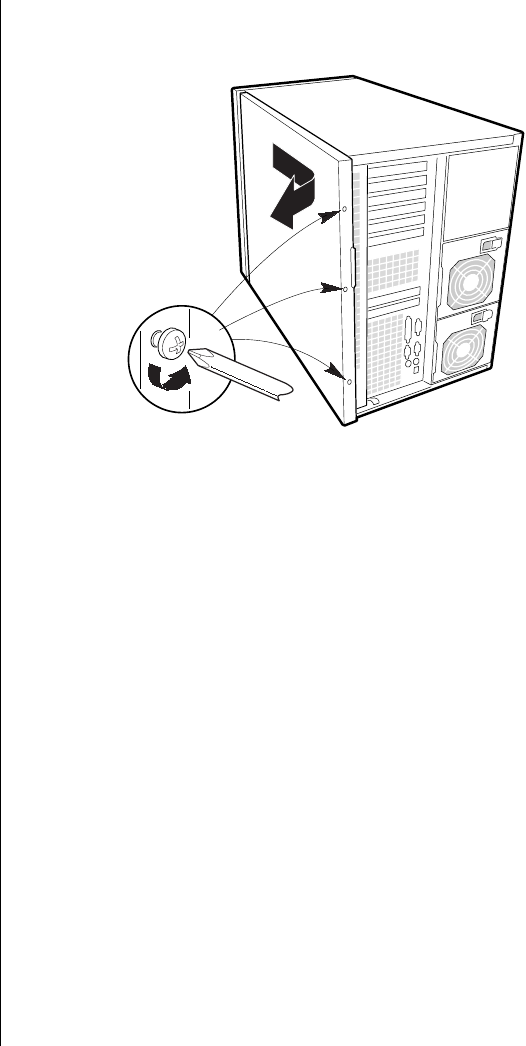
8. Loosen the two screws on the top and bottom edges of the chassis (A
in Figure 2). These screws attach the front subchassis and the
electronics bay to the main chassis.
Figure 2: Opening the Subchassis and Electronics Bay
9. Using the edges of the subchassis as handles, rotate the front
subchassis left, away from the main chassis, until it stops (B in
Figure 2).
10. Disconnect all cabling to the electronics bay (D in Figure 2).
11. Using the vertical edge of the electronics bay as a handle, rotate the
bay right, away from the main chassis, until it stops (C in Figure 2).
12. If necessary, completely remove the subchassis and electronics bay:
rotate the bays outward until the two pins that function as hinges for
the bays slide out of their slots. Set the bays aside.
Caution!
You must disconnect all
cabling to the electronics
bay before rotating/
removing the bay. Failure to
do so can result in serious
damage to system
components. The location of
the main connectors in the
electronics bay is marked as
D in Figure 2.
B
A
C
D
Note:
It may be easier to
disconnect the cables if you
remove the foam pad first.
3424.boo Page 6 Wednesday, September 2, 1998 9:23 AM

Closing the System 7
Closing the System
Before closing the system, verify that all connectors and boards are
properly installed and firmly seated.
Closing the Subchassis and Electronics Bay
As you close the subchassis and electronics bay, carefully observe the
internal components to ensure that you do not pinch or twist any of the
cables or components.
1. Verify that all internal components are fully installed and secured.
2. Press down on the tab on the top of the electronics bay to release it and
swing it closed.
3. Attach any cables to the electronics bay components.
4. Press down on the tab at the top of the subchassis to free it and swing it
closed.
5. Secure the subchassis with the two screws you removed earlier.
6. If necessary, reinstall the foam bracketing for the fans in the
subchassis and reinstall the fans.
7. Reinstall the foam over the subchassis and electronics bay.
8. Replace the access cover and power up the system.
To Close the Subchassis and Electronics Bay
3424.boo Page 7 Wednesday, September 2, 1998 9:23 AM

8 Maintaining and Troubleshooting the Gateway ALR 9200 Server
Installing the Access Cover
Be careful to avoid pinching any internal cables in the access cover when
closing the system.
1. Before replacing the access cover, check that you have not left loose
tools or parts inside the system.
2. Check that cables, expansion cards, foam pad, and other components
are properly installed.
3. Position the cover over the chassis so that the rows of tabs align with
slots in the chassis. While pressing inward, slide the cover toward the
front of the system until the tabs on the cover firmly engage in the
chassis.
4. Attach the cover to the chassis with the three screws you removed
earlier, and tighten them firmly.
5. Connect all external cables and the power cords to the system.
Installing the Front Door
To replace the front door, insert the hinges into the slots on the front of the
chassis and close the door. Secure it by turning the bezel keylock to the
second locked position. The first position allows you to open the front door
and locks the side access panel. The fully locked position prevents all
access to the system controls by locking both the access panel and the bezel
door.
To Replace the Access Cover
Note:
The bezel key lock must be
in the open position before
reinstalling the access cover.
3424.boo Page 8 Wednesday, September 2, 1998 9:23 AM

Chapter 2:
Components
Contents
System Board Features...................................................10
System Board Connectors..............................................10
Drive Controllers and Connectors..........................12
System Jumpers (B)................................................13
Miscellaneous Connectors......................................14
Expansion Slot Connectors ....................................15
Memory Module Connector (I)..............................16
System Management Connectors...........................16
Back Panel I/O Connectors ....................................18
Processors and Related Connectors .......................20
Power Connectors...................................................21
Memory...........................................................................23
DIMM Installation Sequence.................................24
System Memory Addressing..................................24
Memory Configuration...........................................25
System Security ..............................................................26
Mechanical Locks and Monitoring........................26
Software Locks via the SSU or BIOS Setup..........26
3424.boo Page 9 Wednesday, September 2, 1998 9:23 AM

10 Maintaining and Troubleshooting the Gateway ALR 9200 Server
System Board Features
The system board functions as the main interface between the processor,
memory, and peripherals.
Table 1 lists the features of the system board. Figure 3 on page 11 shows the
components on the system board and their locations.
System Board Connectors
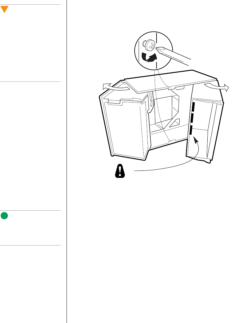
Figure 3 shows the connectors on the system board. Some of these
connectors may not be used, depending on the configuration of the server.
The table below provides the key to Figure 3.
Table 1: System Board Features
Feature Description
Processor Installed: Up to four Pentium® II Xeon™ processors, in single
edge contact (SEC) cartridges installed in Slot 2 connectors.
Includes connectors for six VRM 8.3-compliant plug-in voltage-
regulator modules (VRMs).
Main memory Single plug-in module containing 16 dual in-line memory module
(DIMM) sockets for up to 4 GB of extended data output (EDO)
dynamic random access memory (DRAM).
Installed: 256 MB–4 GB of EDO error correcting code (ECC)
random access memory (RAM).
Video memory Installed: 2 MB of video memory.
PCI bus(es) PCI-A—Three expansion connectors
PCI-B—Four expansion connectors (one shared with the
ISA slot)
ISA bus One expansion slot for expansion boards (shared with a
PCI-B slot).
Server management Thermal/voltage monitoring and error handling.
Front panel controls and indicator light emitting diodes (LEDs).
Graphics Integrated onboard Cirrus Logic GD5480 super video graphics
array (SVGA) controller.
SCSI Two embedded small computer systems interface (SCSI)
controllers:
Symbios SYM53C810AE—narrow SCSI controller providing
support for legacy 8-bit SCSI devices
Symbios SYM53C896—dual-channel wide low voltage
differential (LVD)/single-ended (SE) (ultra2/ultra) SCSI controller
driving one SCSI backplane in the system and providing support
for external expansion.
System I/O PS/2-compatible keyboard and mouse ports, parallel port,
video port, USB port, and two serial ports (serial port 1 is the left
connector).
3424.boo Page 10 Wednesday, September 2, 1998 9:23 AM
System Board Connectors 11
Figure 3: System Board Components and Connectors
A Wide SCSI B connector (J9J1) T VRM connector for processors 2 & 1 (J4A2)
B System jumpers (J6J1) U VRM connector for processor 1 (J4A1)
C Hard drive input LED connector (J6J3) V Processor 1 Slot 2 connector (J9A1)
D System speaker connector (J6J2) W Main power connector, primary (J9B1)
E Lithium battery (B4H1) X Processor 2 Slot 2 connector (J9B2)
F Wake-on-LAN technology connector (J4H1) Y Processor 3 Slot 2 connector (J9D1)
G ISA slot (J1J1) Z Main power connector, secondary (J9D2)
H PCI slots B4 (top), B3, B2, B1, A3, and A2 AA Front panel connector (J8E1)
I Memory module connector (J3G1) BB Processor 4 Slot 2 connector (J9E1)
J ICMB connector (J1E1) CC IDE connector (J9E2)
K PCI slot A1 (J2D1) DD Diskette drive connector (J9E3)
L Video and parallel port connectors (J1C1) EE Auxiliary power connector (J9E4)
M Serial port connectors (J1B2) FF USB internal header (JC9F14)
N Keyboard and mouse connectors (J1B1) GG SMBus connector (J9F2)
O USB external connector (J1A1) HH F16 expansion connector (J7G1)
P VRM connector for processor 4 (J4E1) II Narrow SCSI connector (J9H1)
Q VRM connector for processors 4 & 3 (J4C2) JJ External IPMB connector (J7H1)
R VRM connector for processor 3 (J4C1) KK SMM connector (J8H1)
S VRM connector for processor 2 (J4B1) LL Wide SCSI A connector (J9H2)
LL
KK
JJ
GG
EE
CC
AA
II
FF
Z
W
BB
Y
X
V
DD
HH
L
K
I
J
G
H
M
N
O
C DA E FB
P
R
Q
S
T
U
3424.boo Page 11 Wednesday, September 2, 1998 9:23 AM

12 Maintaining and Troubleshooting the Gateway ALR 9200 Server
Drive Controllers and Connectors
The system board supports several controllers and connectors for the
control of the various drives that are or can be installed in the system.
SCSI Connectors
The system board includes two SCSI controllers. A narrow SCSI controller
(SYM53C810AE) is on the PCI-A bus, and a dual-channel wide LVD/SE
(Ultra2/Ultra) SCSI controller (SYM53C896) is on the PCI-B bus. The
narrow controller provides support for legacy 8-bit SCSI devices that may
be installed in the 5.25-inch drive bays. The wide controller drives one
SCSI backplane and provides support for external expansion.
Each controller has its own set of PCI configuration registers and SCSI I/O
registers. As a PCI 2.1 bus master, the wide controller supports burst data
transfers on PCI up to the maximum rate of 132 MB/sec using on-chip
buffers.
No logic, termination, or resistor loads are required to connect devices to
the SCSI controller other than termination in the device at the end of the
cable. The SCSI bus is terminated on the system board with active
terminators that can be disabled.
Wide SCSI A (LL) and Wide SCSI B Connectors (A)
Internally, each wide channel is identical, capable of operations using either
8- or 16-bit SCSI providing 10 MB/sec (Fast-10) or 20 MB/sec (Fast-20)
throughput, or 20 MB/sec (Ultra) or 40 MB/sec (Ultra-wide).
The wide controller contains a high-performance SCSI bus interface. It
supports SE mode with 8-bit (10 or 20 MB/sec) or 16-bit (20 or 40 MB/sec)
transfers and LVD mode with 8-bit (40 MB/sec) or 16-bit (80 MB/sec)
transfers.
Narrow SCSI Connector (II)
The narrow controller contains a high-performance SCSI core capable of
Fast 8-bit SCSI transfers in single-ended mode. It provides programmable
active negation, PCI zero wait-state bursts of faster than 110 MB/sec at 33
MHz, and SCSI transfer rates from 5 to 10 MB/sec.
3424.boo Page 12 Wednesday, September 2, 1998 9:23 AM

System Board Connectors 13
IDE Connector (CC)
This is an integrated Ultra-DMA PCI/IDE interface with an IDE connector
capable of controlling up to two IDE devices. Ultra-DMA provides faster
access to IDE devices that are Ultra-DMA compliant while maintaining
support for IDE devices that do not support the Ultra-DMA specification.
The IDE controller supports:
•PIO and IDE DMA/bus master operations
•Mode 4 timings
•Transfer rates up to 33 MB/sec
•Buffering for PCI/IDE burst transfers
•Master/slave IDE mode
•Up to two drives for one IDE channel
Diskette Drive Connector (DD)
The diskette drive controller and connector on the system board can support
up to two diskette drives of 1.44-MB and 2.88-MB formats.
System Jumpers (B)
These jumpers allow you to set certain characteristics of the system. Some
jumpers are reserved and are not described in this section. Do not change
any jumper unless it is necessary to configure the system. In some cases,
changing the settings of reserved jumpers can cause damage to the system
board.
Clear CMOS Jumper
This jumper allows you to clear the complimentary metal-oxide
semiconductor (CMOS) memory. You should only do this if you cannot
access the normal methods of modifying the CMOS and modifications to
the CMOS are necessary. Clearing CMOS memory returns all BIOS Setup
settings to the default values. This jumper occupies pins 1-3 of the
connector. See “Setting the Jumpers” on page 72 for more information on
setting the CMOS clear jumper.
Note:
Y
ou can connect an IDE
signal cable, up to a
maximum of 18 inches, to
the IDE connector on the
system board. The cable
can support two devices,
one at the end of the cable
and one six inches from the
end.
3424.boo Page 13 Wednesday, September 2, 1998 9:23 AM

14 Maintaining and Troubleshooting the Gateway ALR 9200 Server
Password Clear Jumper
Momentarily setting this jumper allows you to clear the passwords. The
normal jumper position protects the passwords. Use this jumper only if you
have forgotten the passwords and cannot access the system. This jumper
occupies pins 5-7 of the connector. See “Setting the Jumpers” on page 72
for more information on setting the password clear jumper.
Recovery Boot Jumper
The recovery boot jumper should be used only in the event of a failed BIOS
update. If you attempt a BIOS update and the update fails, set this jumper
and reboot the system. The system attempts to recover the previous version
of the BIOS as it boots up. This jumper occupies pins 9-11 of the connector.
See “Setting the Jumpers” on page 72 for more information on setting the
recovery boot jumper.
Miscellaneous Connectors
Hard Drive Input LED Connector (C)
This connector allows you to connect a cable from an add-in hard disk
controller to the system board to allow the add-in controller to activate the
hard drive activity LED on the control panel.
System Speaker Connector (D)
Connects the internal speaker to the system board.
Wake-on-LAN Technology Connector (F)
The wake on local area network (LAN) technology connector allows you to
connect a magic packet-enabled LAN adapter to the system board to
support wake on LAN functionality. Wake on LAN functionality allows a
system in power conservation mode to be awakened by an incoming
message on the network.
3424.boo Page 14 Wednesday, September 2, 1998 9:23 AM

System Board Connectors 15
Front Panel Connector (AA)
The front panel connector provides the signals for the front cover indicator
LEDs and the front cover buttons.
USB Internal Connector (FF)
This connector allows you to connect internal devices that use the USB
interface to the USB controller on the system board.
Lithium Battery (E)
Provides the power to maintain the CMOS memory when the system is
turned off or unplugged.
Expansion Slot Connectors
ISA Slot (G)
The system board has one industry standard architecture (ISA) slot that is
full-length if you do not use the wide SCSI-B connector (and half-length if
you use the wide SCSI-B connector); the ISA slot supports slave-only
boards and is shared with PCI-B slot 4. The ISA bus also supports three
embedded devices: the Super I/O chip, system board management
controller (BMC), and flash memory for the system BIOS. ISA bus
features:
•Bus speed up to 8.33 MHz
•16-bit memory addressing
•Type A transfers at 5.33 MB/sec
•Type B transfers at 8 MB/sec
•8- or 16-bit data transfers
•Plug and Play ready
3424.boo Page 15 Wednesday, September 2, 1998 9:23 AM

16 Maintaining and Troubleshooting the Gateway ALR 9200 Server
PCI slots B4 (top), B3, B2, B1, A3, A2 (H), A1 (K)
The system board has two 32-bit peripheral component interconnect (PCI)
bus segments: PCI-A and PCI-B. These provide seven slots for PCI
expansion cards: three on PCI-A and four on PCI-B. PCI-B4 is shared with
the ISA slot. PCI-A1 supports half-length boards only. The other slots
support full-length boards. PCI bus features:
•33 MHz bus speed
•32-bit memory addressing
•5 V signaling environment
•Burst transfers of up to 133 MB/sec
•8-, 16-, or 32-bit data transfers
•Plug and Play ready
•Parity enabled
Memory Module Connector (I)
The memory module connector supports the memory module. The
memory module is a proprietary card that supports all of the main memory
for the system. The memory module is described in “Memory” on page 23.
System Management Connectors
Server Management features are implemented using one microcontroller,
the system board management controller (BMC).
The BMC and associated circuitry are powered from the 5 V standby line,
which remains active when the system power is switched off.
The primary function of the BMC is to autonomously monitor system
management events and log their occurrence in the nonvolatile system
event log (SEL). These events include overtemperature and overvoltage
conditions, fan failure, or chassis intrusion. While monitoring, the BMC
maintains the nonvolatile sensor data record repository (SDRR), from
which run-time information can be retrieved. The BMC provides an ISA
3424.boo Page 16 Wednesday, September 2, 1998 9:23 AM

System Board Connectors 17
host interface to SDRR information, so software running on the server can
poll and retrieve the current status of the hardware. A shared register
interface is defined for this purpose.
SEL contents can be retrieved after system failure for analysis by field
service personnel using system management tools like Intel® LANDesk®
Server Manager. Because the BMC is powered by 5V_Standby, SEL (and
SDRR) information is also available via the interperipheral management
bus (IPMB). An emergency management board like the Intel LANDesk
server management module (SMM) board can obtain the SEL and make it
remotely accessible using a LAN or telephone line connection.
During monitoring, the BMC performs the following functions:
•System board temperature and voltage monitoring
•Processor presence monitoring and fault resilient boot (FRB)
control
•System board fan failure detection and indicator control
•SEL interface management
•SDRR interface management
•SDR/SEL timestamp clock
•System board field replaceable unit (FRU) information interface
•System management watchdog timer
•Periodic system management interrupt (SMI) timer
•Front panel non-maskable interrupt (NMI) handling
•Event receiver
•ISA host and IPMB interface management
•Secure mode control, front panel lock/unlock initiation, and video
blank and diskette write protect monitoring and control
•Sensor event initialization agent
•Wake-on-LAN via Magic Packet support
•ACPI Support
•Emergency Management Port (EMP) support
3424.boo Page 17 Wednesday, September 2, 1998 9:23 AM

18 Maintaining and Troubleshooting the Gateway ALR 9200 Server
ICMB Connector (J)
The intelligent chassis management bus (ICMB) connector allows the
connection of a system management component to monitor the chassis
characteristics including temperature, voltages, intrusion detection, and fan
speeds.
SMBus Connector (GG)
This connector supports an SMBus card that provides system management
functions.
F16 Expansion Connector (HH)
The F16 expansion connector allows you to connect a component to the
F16 bus which communicates between the memory and I/O controller
(MIOC) and the PCI expansion bridge (PXB).
External IPMB connector (JJ)
This connector allows you to connect an “external” device to the IPMB to
help determine the cause of a system failure from a remote terminal.
SMM connector (KK)
The SMM connector allows you to connect a system management module
to the system board to monitor the system and perform other system
management functions.
Back Panel I/O Connectors
Video Port Connector (L)
The onboard, integrated Cirrus Logic CL-GD5480 64-bit VGA chip
contains an SVGA controller that is fully compatible with the VGA video
standard. The system board provides 2 MB of 10 ns onboard video
3424.boo Page 18 Wednesday, September 2, 1998 9:23 AM

System Board Connectors 19
memory. The video controller supports pixel resolutions of up to
1600 x 1200 and up to 16.7 M colors. You cannot add video memory to this
system.
The SVGA controller supports analog VGA monitors (single and multiple
frequency, interlaced and noninterlaced) with a maximum vertical retrace
noninterlaced frequency of 100 Hz. Depending on the environment, the
controller displays up to 16.7 M colors in some video resolutions.
Compatible video drivers are provided with the operating system or the
utilities.
Parallel Port Connector (L)
The 25/15-pin connector stacks the parallel port beside the VGA video port.
BIOS programming of the super I/O chip registers enables the parallel port
and determines the port address and interrupt. The system BIOS provides
fields in the setup utility to easily enable the parallel port and set the port
address and interrupt. When disabled, the interrupt is available to expansion
cards.
Serial Port Connectors (M)
Both serial ports are relocatable. By default, port 1 is the left connector,
port 2 on the right. Each serial port can be set to one of four different
COMx ports, and each can be enabled separately. The system BIOS
provides fields in the setup utility to easily enable both serial ports and set
the port addresses and interrupts. When disabled, serial port interrupts are
available to expansion cards.
Keyboard and Mouse Connectors (N)
The PS/2-compatible keyboard and mouse connectors are mounted in a
single-stacked housing with the mouse connector to the left of the
keyboard. External to the system, they appear as two connectors.
You can plug in the keyboard and mouse to either connector before
powering up the system. BIOS detects the device connected at each
connector and configures the keyboard controller accordingly.
3424.boo Page 19 Wednesday, September 2, 1998 9:23 AM
20 Maintaining and Troubleshooting the Gateway ALR 9200 Server
The keyboard controller is functionally compatible with the 8042A
microcontroller. The system can be locked automatically if no keyboard or
mouse activity occurs for a predefined length of time, if specified through
the SSU. Once the inactivity (lockout) timer has expired, the keyboard and
mouse do not respond until the previously stored password is entered.
USB External Connector (O)
One universal serial bus (USB) port provides connection for a growing list
of peripheral components including mouse, keyboard, joystick, monitor,
tape and diskette drives. Up to 127 devices can be daisy-chained from the
port. The USB port also provides hot-swap capability and dynamic resource
allocation for all peripherals attached to it with data transfer rates of up to
12 Mbps. USB drivers are provided as a part of most major operating
systems and should require no special procedures for implementation or
use.
Processors and Related Connectors
VRM Connectors (P, Q, R, S, T, U)
In this system each processor must have one VRM to adjust the voltage
supplied to the processor core and one to adjust the voltage supplied to the
second-level cache in the SEC cartridge. The first VRM is dedicated to a
single processor and provides the correct power to the processor core. The
second VRM provides power to the integrated second-level cache and can
support the cache on two SEC cartridges. Therefore each processor requires
1.5 VRMs. See Table 2 for the allowed processor and VRM configurations.
Table 2: Processors and VRMs
Processor
Installed VRM
Installed VRM Function
Processor 1 VRM 1 Powers the processor core for processor 1
VRM 2 Powers the second-level cache for processors 1 and 2
Processor 2 VRM 3 Powers the processor core for processor 2
Processor 3 VRM 4 Powers the processor core for processor 3
VRM 5 Powers the second-level cache for processors 3 and 4
Processor 4 VRM 6 Powers the processor core for processor 4
Note:
A second USB port internal
to the system chassis is
provided at position FF as
shown in Figure 3 on
page 11
3424.boo Page 20 Wednesday, September 2, 1998 9:23 AM

System Board Connectors 21
Processor Slots (V, X, Y, AB)
Each Pentium® II Xeon™ processor is packaged in a SEC cartridge. The
cartridge includes the processor core with an integrated 16 KB primary
(L1) cache; the secondary (L2) cache; a thermal plate; and a back cover.
The processor implements MMX™ technology and maintains full
backward compatibility with the 8086, 80286, Intel386™, Intel486™,
Pentium, and Pentium Pro processors.
Each SEC cartridge connects to the system board through a Slot 2 edge
connector. The cartridge is secured by a retention bracket attached to the
system board. Depending on configuration, the server has one to four
processors.
The processor external interface is multiprocessor (MP)-ready and operates
at 100 MHz. The processor contains a local advanced programmable
interrupt controller (APIC) for interrupt handling in MP and uniprocessor
(UP) environments. The system SMP design supports up to four processors
and is Intel MP Specification v1.1 and 1.4 compliant.
The second-level cache is located inside the SEC cartridge. The cache
includes burst pipelined synchronous static RAM (BSRAM) and is offered
in 512 KB, 1 MB, and 2 MB configurations, with ECC that operates at the
full core clock rate.
Each processor cartridge requires two VRMs to provide power to the
processor core and the second-level cache, respectively. The full details of
the installation of processors and VRMs are provided in “VRM Connectors
(P, Q, R, S, T, U)” on page 20.
Power Connectors
There are several power connectors that provide power for the system
board. Some of these connectors provide power for specialized functions.
Main Power Connector, Primary (W)
The primary power connectors provide the majority of the power to the
system board. These connectors are designed to accommodate the power
supply installed in the system.
3424.boo Page 21 Wednesday, September 2, 1998 9:23 AM

22 Maintaining and Troubleshooting the Gateway ALR 9200 Server
Main Power Connector, Secondary (Z)
The primary power connectors provide the majority of the power to the
system board. These connectors are designed to accommodate the power
supply installed in the system.
Auxiliary Power Connector (EE)
The auxiliary power connector provides for the connection of an additional
power source.
3424.boo Page 22 Wednesday, September 2, 1998 9:23 AM
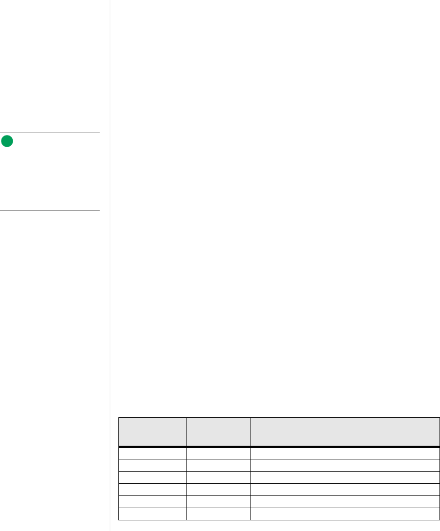
Memory 23
Memory
The system comes standard with 256-MB of ECC RAM. System RAM is
expandable up to 4-GB using ECC 50- or 60-ns 72-bit EDO DIMMs
(16 DIMM sockets) with gold contacts.
Main memory resides on an expansion card, called a memory module,
designed specifically for this server. The memory module contains slots for
16 DIMMs, each of which must be at least 32 MB, and is attached to the
system board through a dedicated connector. Memory amounts from
128 MB to 4 GB of RAM are supported, with a 64/72-bit
four-way-interleaved pathway to main memory.
The 16 slots are divided into four banks of four slots each, labeled A
through D. These banks support 4:1 interleaving. The memory controller
supports EDO DRAMs. The ECC used for the memory module is capable
of correcting single-bit errors (SBEs) and detecting 100 percent of double-
bit errors over one code word. Nibble error detection is also provided.
Figure 4: Memory Banks
J16
J15
J12
J11
J8
J7
J3
J4
J14
J13
J10
J9
J6
J5
J1
J2
D
C
B
A
E
3424.boo Page 23 Wednesday, September 2, 1998 9:23 AM

24 Maintaining and Troubleshooting the Gateway ALR 9200 Server
DIMM Installation Sequence
You must install DIMMs in the correct order and in entire banks. All
DIMMs in the bank must be the same size and speed. DIMMs in other
banks may differ in size. If you use slower DIMMs in another bank, all
DIMMs operate at the slower speed (see Figure 4 on page 23).
The sequence in which you must fill the banks is:
1. Memory bank A
2. Memory bank B
3. Memory bank C
4. Memory bank D
System Memory Addressing
System memory begins at address 0 and is continuous (flat addressing) up
to the maximum amount of DRAM installed (exception: system memory is
noncontiguous in the ranges defined as memory holes using configuration
registers). The system supports both base (conventional) and extended
memory.
•Base memory is located at addresses 00000h to 9FFFFh (the first
1MB).
•Extended memory begins at address 0100000h (1 MB) and
extends to FFFFFFFFh (4 GB), which is the limit of supported
addressable memory. The top of physical memory is a maximum
of 4 GB (to FFFFFFFFh)
Memory holes can be configured in Setup or the SSU and are used by some
legacy ISA boards. If you do not need to set up a memory hole for an ISA
expansion board, leave the memory in a contiguous state for optimal
performance.
Note:
Each memory bank includes
two DIMM sockets in each
row of connectors. When
installing DIMMs, be careful
to install the DIMMs in the
correct sockets for the bank.
3424.boo Page 24 Wednesday, September 2, 1998 9:23 AM
Memory 25
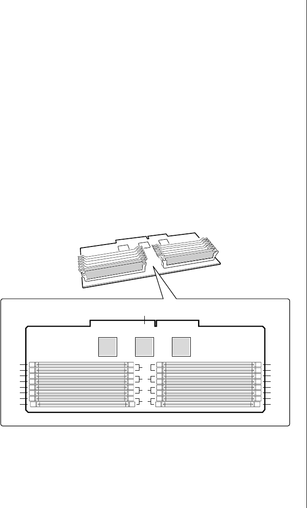
Memory Configuration
BIOS automatically detects, sizes, and initializes the memory array,
depending on the type, size, and speed of the installed DIMMs, and reports
memory size and allocation to the system via configuration registers.
In a 4 GB configuration, a small part of memory (typically 32 MB) is not
remapped above 4 GB. If your OS does not support more than 4 GB of
physical memory, this small part of the memory is effectively lost.
Table 3: Sample DIMM Component Combinations
Bank A
(slots J1 - 4) Bank B
(slots J5 - 8) Bank C
(slots J9 - 12) Bank D
(slots J13 - 16) To ta l
Memory
4x64 256 MB
4x64 4x32 384 MB
4x64 4x32 4x32 512 MB
4x64 4x64 512 MB
4x64 4x64 4x32 4x32 768 MB
4x64 4x64 4x64 4x64 1024 MB
4x128 4x64 4x32 4x32 1024 MB
4x128 4x128 4x64 4x64 1536 MB
4x128 4x128 4x128 4x128 2048 MB
4x256 4x128 4x64 4x64 2048 MB
4x256 4x256 4x128 4x128 3072 MB
4x256 4x256 4x256 4x256 4096 MB
Note:
Use DIMMs that have been
tested for compatibility with
the system board. Contact
your sales representative or
dealer for a list of approved
DIMMs. Table 3 lists some
sample size combinations.
3424.boo Page 25 Wednesday, September 2, 1998 9:23 AM

26 Maintaining and Troubleshooting the Gateway ALR 9200 Server
System Security
To help prevent unauthorized entry or use of the system, the system
includes a three-position key lock/switch to permit selected access to drive
bays (position is communicated to the BMC, see “System Management
Connectors” on page 16). The system also includes server management
software that monitors the chassis intrusion switch.
Mechanical Locks and Monitoring
The system includes a chassis intrusion switch. When the access cover is
opened, the switch transmits an alarm signal to the system board, where
server management software processes the signal. You can program a
response to an intrusion, for example, the system may power down or lock
the keyboard.
Software Locks via the SSU or BIOS Setup
The system setup utility (SSU) provides a number of security features to
prevent unauthorized or accidental access to the system. Once the security
measures are enabled, access to the system is allowed only after you enter
the correct password(s). For example, the SSU allows you to:
•Enable the keyboard lockout timer so the server requires a
password to reactivate the keyboard and mouse after a specified
time-out period of 1 to 120 minutes
•Set and enable administrator and user passwords
•Set secure mode to prevent keyboard or mouse input and to prevent
use of the front panel reset and power switches
•Activate a hot-key combination to enter secure mode quickly
•Disable writing to the diskette drive when secure mode is set
3424.boo Page 26 Wednesday, September 2, 1998 9:23 AM

System Security 27
Using Passwords
If you set and enable a user password but not an administrator password,
enter the user password to boot the system and run the SSU.
If you set and enable both a user and an administrator password:
•Enter either one to boot the server and enable the keyboard and
mouse
•Enter the administrator password to access the SSU or BIOS Setup
to change the system configuration
Secure Mode
Configure and enable the secure boot mode by using the SSU. When secure
mode is in effect, you:
•Can boot the system and run the OS, but you must enter the user
password to use the keyboard or mouse
•Cannot turn off system power or reset the system from the front
panel switches
Secure mode has no effect on functions enabled via the Server Manager
Module or power control via the real-time clock (RTC).
Taking the system out of secure mode does not change the state of system
power. That is, if you press and release the power switch while secure mode
is in effect, the system will not power off when secure mode is later
removed. However, if the front panel power switch remains depressed when
secure mode is removed, the system will power off.
3424.boo Page 27 Wednesday, September 2, 1998 9:23 AM

28 Maintaining and Troubleshooting the Gateway ALR 9200 Server
Summary of Software Security Features
Table 4 lists the software security features and describes what protection
each offers. In general, to enable or set the features listed here, you must run
the SSU and go to the Security Menu (described in “Security Add-in” on
page 116). The table also refers to other SSU menus and to the Setup utility.
For more information on setting the security features, see “Security Menu”
on page 92, and “Security Add-in” on page 116.
Table 4: Software Security Features
Feature Description
Secure boot mode To enter secure mode:
Set and enable a password to automatically put the system into secure
mode.
If you set a hot-key combination, you can secure the system by pressing
the key combination. This means you do not have to wait for the
inactivity time-out period. See “Security Menu” on page 92.
When the system is in secure mode:
The system boots and runs the OS, but does not accept mouse or
keyboard input until you enter the user password.
At bootup, if the system detects a CD in the CD-ROM drive or a diskette
in drive A, it requests a password. When you enter the password, the
system boots from CD or diskette and disables secure mode.
If you have not installed a CD-ROM drive or if there is no CD in the drive
or diskette in drive A, the system boots from drive C and automatically
enters secure mode. All enabled secure mode features go into effect at
bootup.
To leave secure mode:
Enter the correct password(s).
Disable writing to diskette In secure mode, the system will not boot from or write to a diskette
unless a password is entered. To set these features, see “Security
Menu” on page 92 and “Security Options” on page 117.
Disable the power and reset
buttons If you enable this protection feature in the SSU, the system disables the
power and reset buttons when in secure mode. See “Security Options”
on page 117.
Set a time-out period so that
keyboard and mouse input
are not accepted.
Also, blank screen and inhibit
writes to diskette
You can specify and enable an inactivity time-out period of from 1 to
120 minutes. If no keyboard or mouse action occurs for the specified
period, keyboard and mouse input is not accepted. To set this feature,
see “Security Menu” on page 92.
If video blanking is enabled, the monitor display goes blank until you
enter the correct password(s). To set this feature, see “Security Menu”
on page 92.
Control access to the SSU:
set administrator password To control access to the system configuration, set an administrator
password and enable it through Setup or the SSU.
If both the administrator and user passwords are enabled, either can be
used to boot the system or enable the keyboard and/or mouse, but only
the administrator password allows changes to Setup and the SSU.
Once set, passwords can be disabled by setting the password to a null
string or by changing the Clear Password jumper. See “Security Add-in”
on page 116 to set the password to a null string; or, to change the
jumper, see “Password Clear Jumper” on page 75.
3424.boo Page 28 Wednesday, September 2, 1998 9:23 AM

System Security 29
Control access to the system
other than SSU: set user
password
To control access to the system, set a user password and enable the
Password on Boot field through Setup or the SSU.
Once set, passwords can be disabled by setting the password to a null
string or by changing the Clear Password jumper. See “Security Add-in”
on page 116 to set the password to a null string; or, to change the
jumper, see “Password Clear Jumper” on page 75.
Boot without keyboard The system can boot with or without a keyboard. During POST and
before the system boots, BIOS automatically detects and tests the
keyboard, if present, and displays a message. No entry exists in the SSU
for enabling or disabling a keyboard. Do not plug in a keyboard while
power is applied to the system.
Specify the boot sequence The sequence you specify in the BIOS (see “Boot Device Priority
Submenu” on page 96) or the SSU (see “Multiboot Options Add-in” on
page 115) determines the boot order. If secure mode is enabled (user
password is set), you are prompted for a password before the system
boots fully. If secure mode is enabled and the Secure Mode Boot option
is also enabled, the system boots fully but requires a password before
accepting any keyboard or mouse input.
Table 4: Software Security Features (Continued)
Feature Description
3424.boo Page 29 Wednesday, September 2, 1998 9:23 AM

30 Maintaining and Troubleshooting the Gateway ALR 9200 Server
3424.boo Page 30 Wednesday, September 2, 1998 9:23 AM

Chapter 3:
Installing
Components
Contents
Introduction............................................................ 32
Replacing the Processor ........................................ 32
Installing Another Processor................................. 36
Installing Hardware............................................... 40
Memory........................................................... 40
Drives.............................................................. 45
Installing Fans for High-Power Drives.......... 57
Expansion Cards............................................. 62
Power Supplies............................................... 65
Replacing the Battery..................................... 68
3424.boo Page 31 Wednesday, September 2, 1998 9:23 AM

32 Maintaining and Troubleshooting the Gateway ALR 9200 Server
Introduction
This chapter provides step-by-step instruction for installing, removing, or
replacing several system components. Only authorized service personnel
should perform these procedures. Follow all standard safety and ESD
precautions when servicing the server. See “Static Electricity Precautions”
on page 2 for more information on ESD precautions.
“Opening the System” on page 3 provides detailed instructions for opening
the system. All procedures in this chapter assume that any necessary access
covers have been removed and that the subchassis and electronics bays have
been removed, if necessary.
Replacing the Processor
The system is compatible with Intel Pentium® II Xeon™ processors. You
can either upgrade the existing Pentium II Xeon processor or install up to
three more processors of the same speed and cache size as the first
processor.
When replacing a processor, order a Pentium II Xeon processor upgrade kit.
The kit includes the Pentium II Xeon processor, a heat sink, and latches.
It is critical that a heat sink be installed on each processor. The Pentium II
Xeon processor overheats and fails if it is not cooled sufficiently. The heat
sink provided with the processor in the system provides all necessary
cooling for the processor.
For the latest details on the availability of the upgrade kits, contact one of
the sources listed in the Assistance Resources document.
1. Turn off the system and disconnect all the power cords.
2. Open the case, observing the static electricity precautions in “Static
Electricity Precautions” on page 2 and remove the foam cover on the
electronics bay.
To Replace the Processor
Caution!
ESD can damage disk
drives, expansion cards, and
other components. The
server can withstand normal
levels of environmental ESD
while you hot-swap SCSI
hard drives. However, we
recommend doing all
procedures at an ESD-
protected workstation. If one
is not available, you can
provide some ESD
protection by wearing an
antistatic wrist strap
attached to chassis ground
of the server when handling
components.
Note:
If the server has less than
four processors and you are
adding one, then you must
remove the termination
board assembly from the
next Slot 2 connector before
you install the new
processor. If you plan to
reduce the number of
processors in your system,
then you must replace a
processor with a termination
board assembly.
3424.boo Page 32 Wednesday, September 2, 1998 9:23 AM
Replacing the Processor 33
3. Wear an anti-static wristband grounded to the system chassis and
place processors on a grounded, static-free surface or conductive foam
pad.
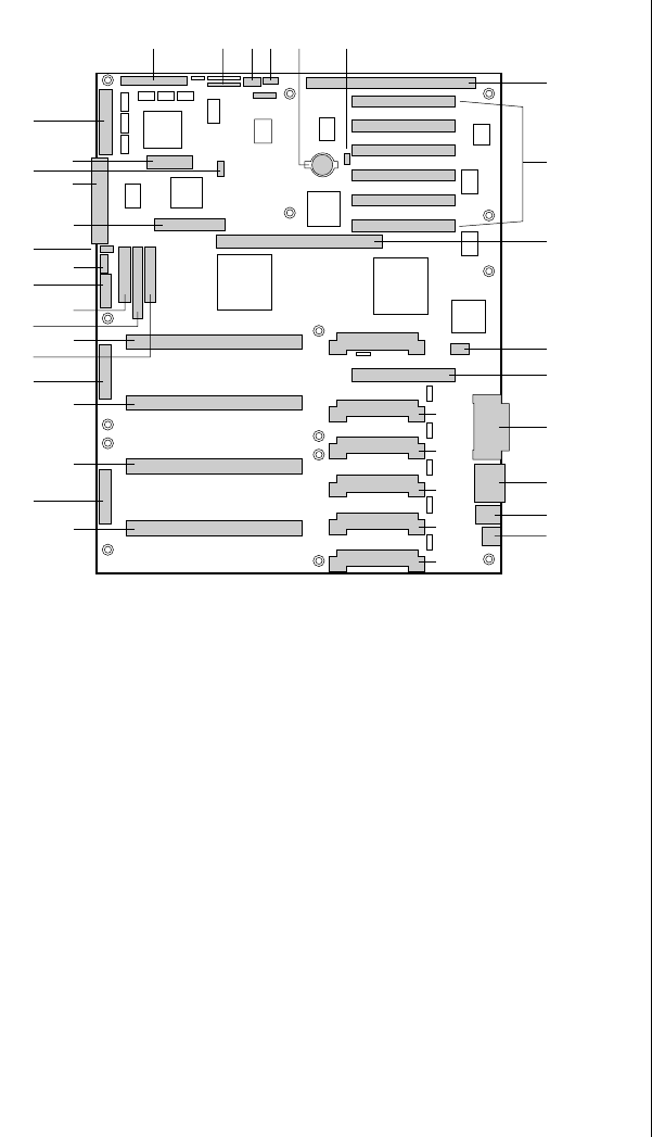
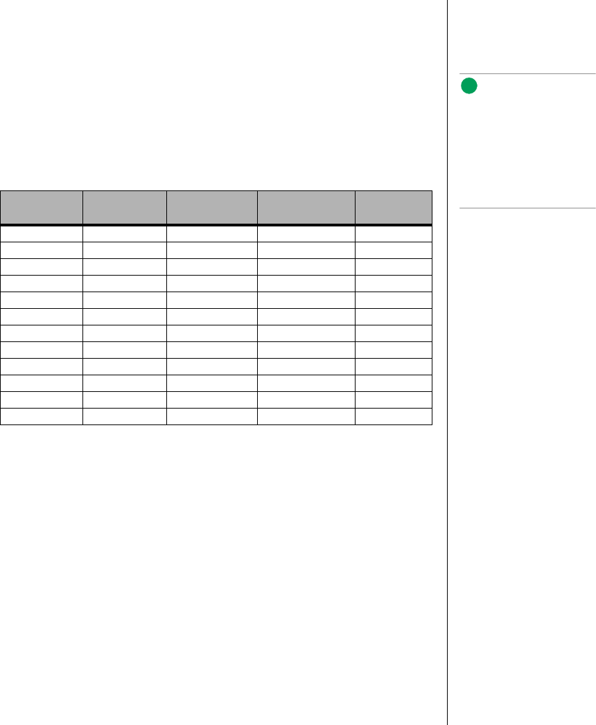
4. With your right thumb on the face of the retention module bracket (A
in Figure 5), wrap your right index finger around the tab (B in
Figure 5) protruding from the right edge of the bracket.
Figure 5: Releasing the Retention Module Bracket
5. Use your index finger to slightly pull the tab outward and to the left.
You should not try to pull the entire bracket; rather, the back of the tab
has a latch (C in Figure 5) that releases when the tab is pulled slightly.
6. When you have released the right edge of the bracket, rotate it 90° to
the left until it is perpendicular to the front of the retention module.
The left edge of the bracket has an open hinge that can release from
the module when you rotate the bracket to the left.
7. Disengage the open hinge by moving (not rotating) the entire bracket
to the right. Remove the bracket and set it aside.
A
B
Latch
3424.boo Page 33 Wednesday, September 2, 1998 9:23 AM
34 Maintaining and Troubleshooting the Gateway ALR 9200 Server
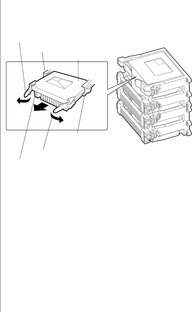
8. Pull the two tabs attached to the single edge contact (SEC) cartridge
(visible after you remove the bracket—C in Figure 6) straight away
from the system board. As you do, the cartridge disengages from the
connector on the system board.
Figure 6: Removing a Processor
9. Slide the SEC cartridge straight away from the system board, out of
the retention module. Put it on a piece of conductive foam and store it
in an antistatic package.
10. Remove the replacement processor cartridge from its protective
wrapping.
11. Orient the SEC cartridge so that the heat sink faces away from the
center of the system board.
If you are installing a termination card assembly, orient it so that the
side with the label faces toward the center of the system board.
Tab on SEC cartridge
Retention module guide rails
SEC cartridge
Processor heat sink
Tab on SEC cartridge
Retention module guide rails
3424.boo Page 34 Wednesday, September 2, 1998 9:23 AM
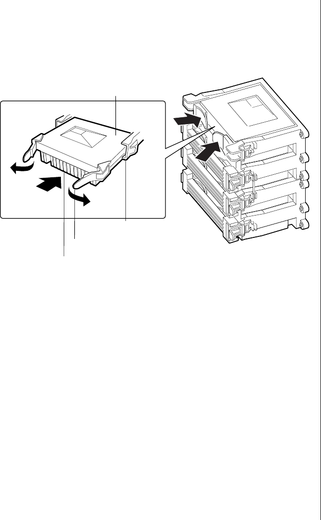
Replacing the Processor 35
12. With the tabs at the top of the SEC cartridge completely open (pulled
outward, away from the center of the cartridge—C in Figure 7), slide
the cartridge into the guide rails of the retention module (B in
Figure 7). When done properly, the triangular ends of the tabs (with
two round pegs on each) fit into the entrance to the guide rails.
Figure 7: Installing a Processor
13. When the cartridge meets resistance, push the two tabs toward each
other (E in Figure 7) until the processor is fully seated.
14. Reattach the retention module bracket:
a. With the bracket in an open position (perpendicular to the front of
the retention module), slide the open hinge at the left of the bracket
into its receptacle at the left of the retention module.
b. Rotate the bracket to the right until it reaches the retention module.
With your right thumb on the face of the bracket and your right index
finger around the tab at the right of the bracket, slightly pull the tab
outward and to the left to open the latch at the back of the tab.
c. As you open the latch on the back of the tab, slide the right edge of
the bracket onto the retention module and release the tab. If done
correctly, the bracket will latch securely.
SEC cartridge
Processor heat sink (must face away
from the center of the system board
Tab on SEC cartridge
Retention module guide rails
3424.boo Page 35 Wednesday, September 2, 1998 9:23 AM

36 Maintaining and Troubleshooting the Gateway ALR 9200 Server
15. Reinstall the foam cover.
16. Close the case, as described in “Closing the System” on page 7.
17. Reconnect the power cord and turn on the system.
Installing Another Processor
The system is compatible with Intel Pentium® II Xeon™ processors. You
can either upgrade the existing processor or install another processor of the
same speed as the original processor.
When adding a processor, order a Pentium II Xeon processor upgrade kit.
The kit includes the Pentium II Xeon processor, a heat sink, and latches.
It is critical that a heat sink be installed on each processor. The Pentium II
Xeon processor overheats and fails if it is not cooled sufficiently. The heat
sink provided with the processor in the system provides all necessary
cooling for the processor.
For the latest details on the availability of the upgrade kits, contact one of
the sources listed in the Assistance Resources document.
1. Turn off the system and disconnect the power cord.
2. Open the case, observing the static electricity precautions in “Static
Electricity Precautions” on page 2 and remove the foam cover on the
electronics bay.
3. Wear an anti-static wristband grounded to the system chassis and
place processors on a grounded, static-free surface or conductive foam
pad.
4. Remove the termination card in the lowest numbered empty processor
slot. (Processor slots are numbered from the bottom up or from the
edge of the system board toward the center of the board.) With your
To Install a Second Processor
Note:
The foam cover is required
to control airflow past the
processors for proper
cooling. Failure to install the
foam cover could result in
damage to the processors
and other system
components.
Note:
If the server has less than
four processors and you are
adding one, then you must
remove the termination
board assembly from the
next Slot 2 connector before
you install the new
processor. If you plan to
reduce the number of
processors in your system,
then you must replace a
processor with a termination
board assembly.
3424.boo Page 36 Wednesday, September 2, 1998 9:23 AM
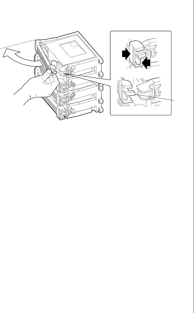
Installing Another Processor 37
right thumb on the face of the retention module bracket (A in
Figure 8), wrap your right index finger around the tab (B in Figure 8)
protruding from the right edge of the bracket.
Figure 8: Releasing the Retention Module Bracket
5. Use your index finger to slightly pull the tab outward and to the left.
You should not try to pull the entire bracket; rather, the back of the tab
has a latch that releases when the tab is pulled slightly.
6. When you have released the right edge of the bracket, rotate it 90° to
the left until it is perpendicular to the front of the retention module.
The left edge of the bracket has an open hinge that can release from
the module when you rotate the bracket to the left.
7. Disengage the open hinge by moving (not rotating) the entire bracket
to the right. Remove the bracket and set it aside.
A
B
Latch
3424.boo Page 37 Wednesday, September 2, 1998 9:23 AM
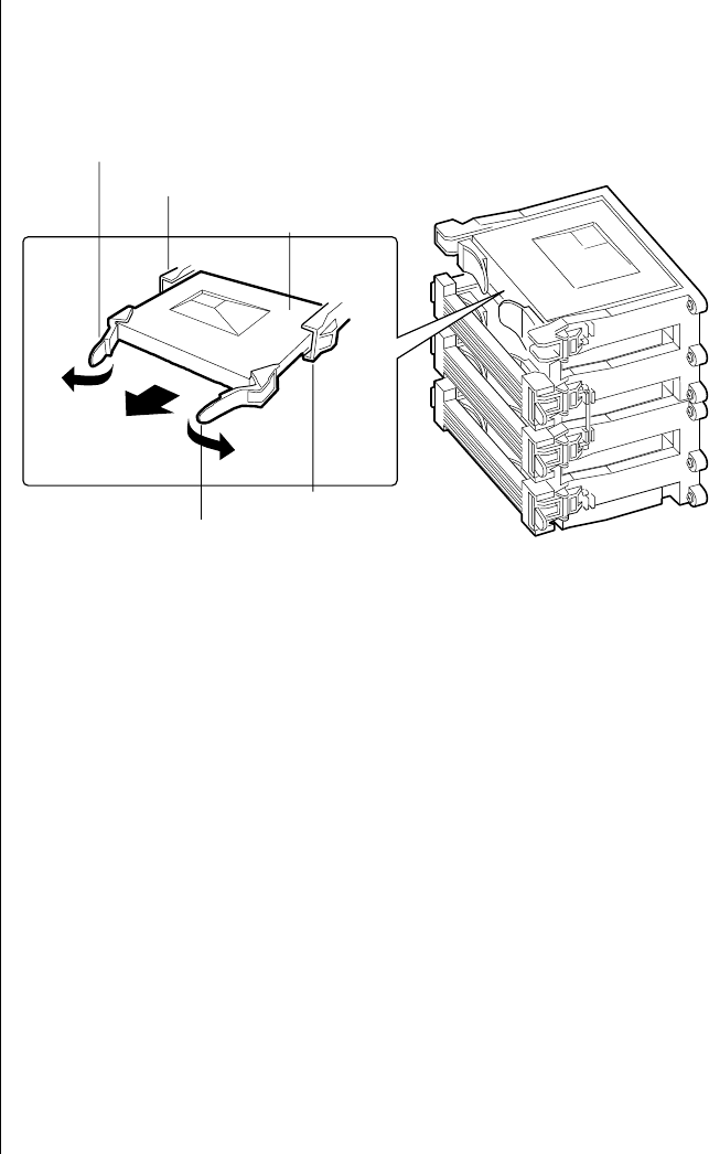
38 Maintaining and Troubleshooting the Gateway ALR 9200 Server
8. Pull the two tabs attached to the termination module (visible after you
remove the bracket—C in Figure 9) straight away from the system
board. As you do, the termination module disengages from the
connector on the system board.
Figure 9: Removing the Termination Module
9. Slide the termination module straight away from the system board, out
of the retention module. Put it on a piece of conductive foam and store
it in an antistatic package.
10. Remove the processor cartridge from its protective wrapping.
11. Orient the S.E.C. cartridge so that the heat sink faces away from the
center of the system board.
12. With the tabs at the top of the S.E.C. cartridge completely open (pulled
outward, away from the center of the cartridge, Figure 10), slide the
cartridge into the guide rails of the retention module (Figure 10).
When done properly, the triangular ends of the tabs (with two round
pegs on each) fit into the entrance to the guide rails.
Tab on retention module
Tab on retention module
Retention module guide rail
Retention module guide rail
Termination module
3424.boo Page 38 Wednesday, September 2, 1998 9:23 AM
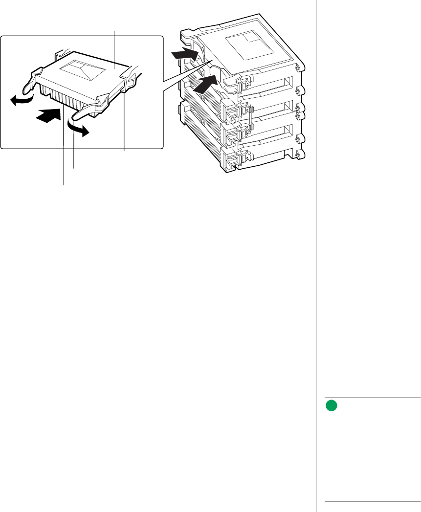
Installing Another Processor 39
Figure 10: Installing a Processor
13. When the cartridge meets resistance, push the two tabs toward each
other (Figure 10) until the processor is fully seated.
14. Reattach the retention module bracket:
a. With the bracket in an open position (perpendicular to the front of
the retention module), slide the open hinge at the left of the bracket
into its receptacle at the left of the retention module.
b. Rotate the bracket to the right until it reaches the retention module.
With your right thumb on the face of the bracket and your right index
finger around the tab at the right of the bracket, slightly pull the tab
outward and to the left to open the latch at the back of the tab.
c. As you open the latch on the back of the tab, slide the right edge of
the bracket onto the retention module and release the tab. If done
correctly, the bracket will latch securely.
15. Reinstall the foam cover.
16. Close the case, as described in “Closing the System” on page 7.
17. Reconnect the power cord and turn on the system.
SEC cartridge
Retention module guide rail
Tab on SEC cartridge
Processor heat sink (must face
away from the system board)
Note:
The foam cover is required
to control airflow past the
processors for proper
cooling. Failure to install the
foam cover could result in
damage to the processors
and other system
components.
3424.boo Page 39 Wednesday, September 2, 1998 9:23 AM

40 Maintaining and Troubleshooting the Gateway ALR 9200 Server
Installing Hardware
The server includes expandability features that allow you to add several
types of hardware to the interior of the system. All of the procedures given
in this section use the ESD precautions identified in “Static Electricity
Precautions” on page 2. All of the procedures in this section refer to
Chapter 2, “Installing Components”.
Memory
Main memory resides on an add-in board, called a memory module. The
memory module contains slots for 16 DIMMs, each of which must be at
least 32 MB, and is attached to the system board through a 242-pin
connector. Memory amounts from 128 MB to 4 GB of DRAM are
supported, with a 64/72-bit four-way-interleaved pathway to main memory.
The 16 slots are divided into four banks of four slots each, labeled A
through D. These banks support 4:1 interleaving. The memory controller
supports EDO DIMMs only. The ECC used for the memory module is
capable of correcting single-bit errors (SBEs) and detecting 100 percent of
double-bit errors over one code word. Nibble error detection is also
provided.
Removing the Memory Module
The memory module must be removed before you can change the memory
configuration. See “Memory” on page 23 for memory size and
requirements.
1. Observe the safety and ESD precautions in “Static Electricity
Precautions” on page 2.
2. Remove the access cover (see “Opening the System” on page 3).
3. Remove the foam cover over the electronics bay.
To Remove the Memory Module
3424.boo Page 40 Wednesday, September 2, 1998 9:23 AM
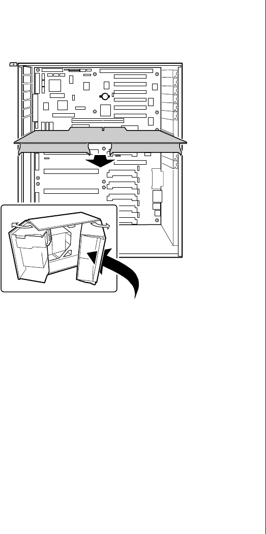
Installing Hardware 41
4. Remove the memory module from the system board by pulling it
gently from the electronics bay (see Figure 11). It is not necessary to
open the electronics bay to remove the memory module.
Figure 11: Removing the Memory Module
5. Place the module component-side up on a nonconductive, static-free
surface.
Removing DIMMs
When adding and removing DIMMs, remember that DIMMs must be
installed or removed by banks. Each bank consists of four DIMM sockets.
All DIMMs in the bank must be installed and all must be of the same size
and speed. See Figure 4 on page 23 for the location of the DIMM sockets in
each bank.
3424.boo Page 41 Wednesday, September 2, 1998 9:23 AM

42 Maintaining and Troubleshooting the Gateway ALR 9200 Server
1. Observe the safety and ESD precautions in “Static Electricity
Precautions” on page 2.
2. Remove the memory module and place it component-side up on a
nonconductive, static-free surface (see “Removing the Memory
Module” on page 40).
3. Gently push the plastic ejector levers out and down to eject a DIMM
from its socket.
4. Hold the DIMM only by its edges, being careful not to touch its
components or gold edge connectors. Carefully lift it away from the
socket and store it in an antistatic package.
5. Repeat steps 3 and 4 to remove other DIMMs as necessary.
If you are replacing DIMMs, proceed to “Installing DIMMs” on
page 43. If you are removing DIMMs, continue this procedure.
6. Reinstall the memory module (see “Installing the Memory Module”
on page 44).
7. Reinstall the foam cover.
8. Reinstall the access cover using the original screws.
9. Connect all external cables and power cords to the system.
10. Turn on the monitor and then the system.
11. Run the SSU/BIOS Setup (see “Advanced Chipset Control Submenu”
on page 91 and “Resource Configuration Add-in Window” on
page 112) to configure the system and to properly set up advanced
memory attributes as required.
To Remove DIMMs
Caution!
Use extreme care when
removing a DIMM. Too
much pressure can damage
the socket. Apply only
enough pressure on the
plastic ejector levers to
release the DIMM.
3424.boo Page 42 Wednesday, September 2, 1998 9:23 AM
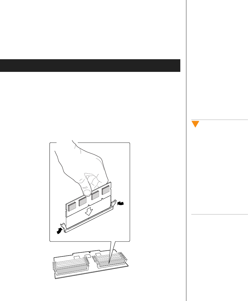
Installing Hardware 43
Installing DIMMs
When adding and removing DIMMs, remember that DIMMs must be
installed or removed by banks. Each bank consists of four DIMM sockets.
All DIMMs in the bank must be installed and all must be of the same size
and speed. See Figure 4 on page 23 for the location of the DIMM sockets in
each bank.
1. Holding the DIMM only by its edges, remove it from its antistatic
package.
2. Orient the DIMM so that the two notches in the bottom edge of the
DIMM align with the keyed socket on the memory module.
3. Insert the bottom edge of the DIMM into the socket, then press down
firmly on the DIMM until it seats correctly (see Figure 12).
Figure 12: Installing a DIMM
To Install DIMMs
Caution!
Use extreme care when
installing a DIMM. Applying
too much pressure can
damage the socket. DIMMs
are keyed and can be
inserted in only one way.
Mixing dissimilar metals
might cause memory failures
later, resulting in data
corruption. Install DIMMs
with gold-plated edge
connectors only in
gold-plated sockets.
3424.boo Page 43 Wednesday, September 2, 1998 9:23 AM

44 Maintaining and Troubleshooting the Gateway ALR 9200 Server
4. Push the ejector levers on the socket ends to the upright position.
5. Repeat steps two through four to install each DIMM.
6. Reinstall the memory module (see “Installing the Memory Module”
on page 44).
7. Reinstall the foam cover(s).
8. Reinstall the access cover using the original screws.
9. Connect all external cables and the power cords to the system.
10. Turn on the monitor and then the system.
11. Run the SSU (see “Resource Configuration Add-in Window” on
page 112) to configure the system and to properly attribute ECC
memory.
Installing the Memory Module
Once you have installed any DIMMs that you want, you must re-install the
memory module.
1. Observe the safety and ESD precautions in “Static Electricity
Precautions” on page 2.
2. Holding the memory module by its edges, align the module so its edge
engages in the guide rail at the back of the electronics bay.
3. Push the memory module toward the system board until it fully
engages its connector.
4. Install the foam pad in the electronics bay.
5. Replace the system access cover and screws.
To Install the Memory Module
Note:
DIMM slots on the memory
module must be installed
only in certain
configurations. See
“Memory Configuration” on
page 25 for requirements.
Caution!
The memory module is held
in place by the 242-pin
connector on the system
board, the guide rail at the
back of the electronics bay,
and a plastic guide at the
front of the electronics bay.
You must support the
module until it is fully seated
in the connector.
3424.boo Page 44 Wednesday, September 2, 1998 9:23 AM

Installing Hardware 45
Drives
The case must be opened to add or replace drives (such as disk drives and
CD-ROM drives) in the system. Refer to “Opening the System” on page 3,
for instructions on opening and closing the case. While SCA-2 SCSI drives
can be added or removed without opening the case, installing and removing
these drives is discussed under “SCSI Hard Disk Drives” on page 54.
The Diskette Drive
The diskette drive is included in the original configuration. If you need to
replace the diskette drive, follow the instructions below.
Removing the Diskette Drive
You should only replace the diskette drive if the originally installed drive
fails.
1. Observe the safety and ESD precautions in “Static Electricity
Precautions” on page 2.
2. Remove the access cover (see “Opening the System” on page 3).
3. Remove the foam and fans from the subchassis. Be sure to label the
fans and fan cables as you remove them.
4. Disconnect the power and signal cables (Figure 13) from the diskette
drive. The connectors are keyed for ease in reconnecting them to the
drive.
To Remove the Diskette Drive
3424.boo Page 45 Wednesday, September 2, 1998 9:23 AM
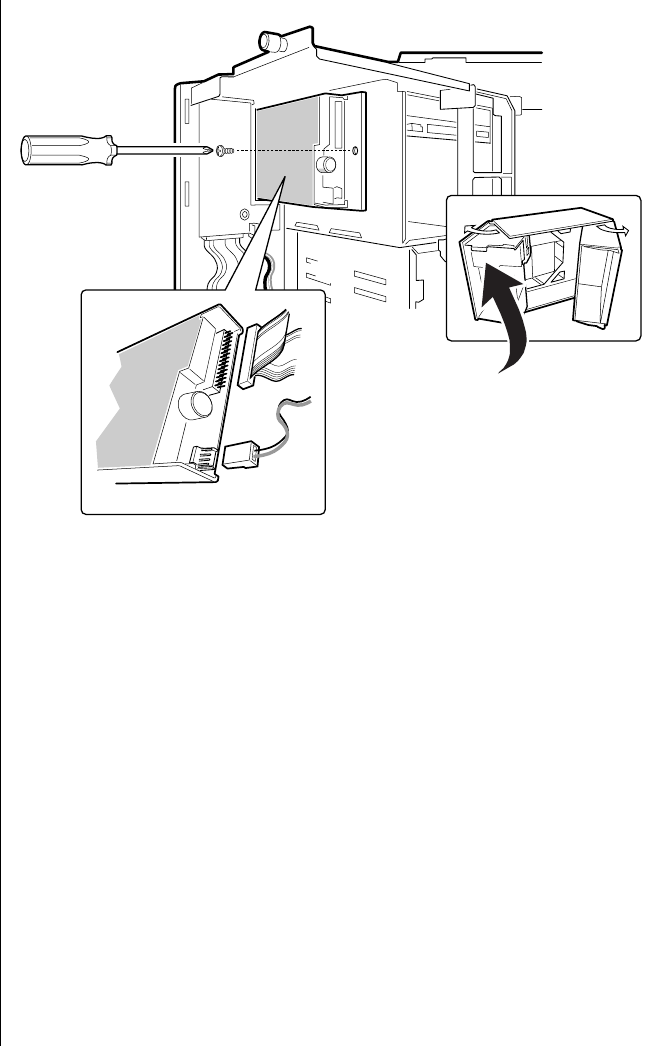
46 Maintaining and Troubleshooting the Gateway ALR 9200 Server
Figure 13: Removing the Diskette Drive
5. Remove and save the screw that secures the diskette drive carrier to the
side of the 5.25-inch drive bay.
6. Slide the carrier toward the back of the chassis to disengage the tabs
from the slots in the side of the 5.25-inch drive bay.
7. Remove the carrier/drive from the chassis and place it component-side
up on an antistatic surface.
3424.boo Page 46 Wednesday, September 2, 1998 9:23 AM
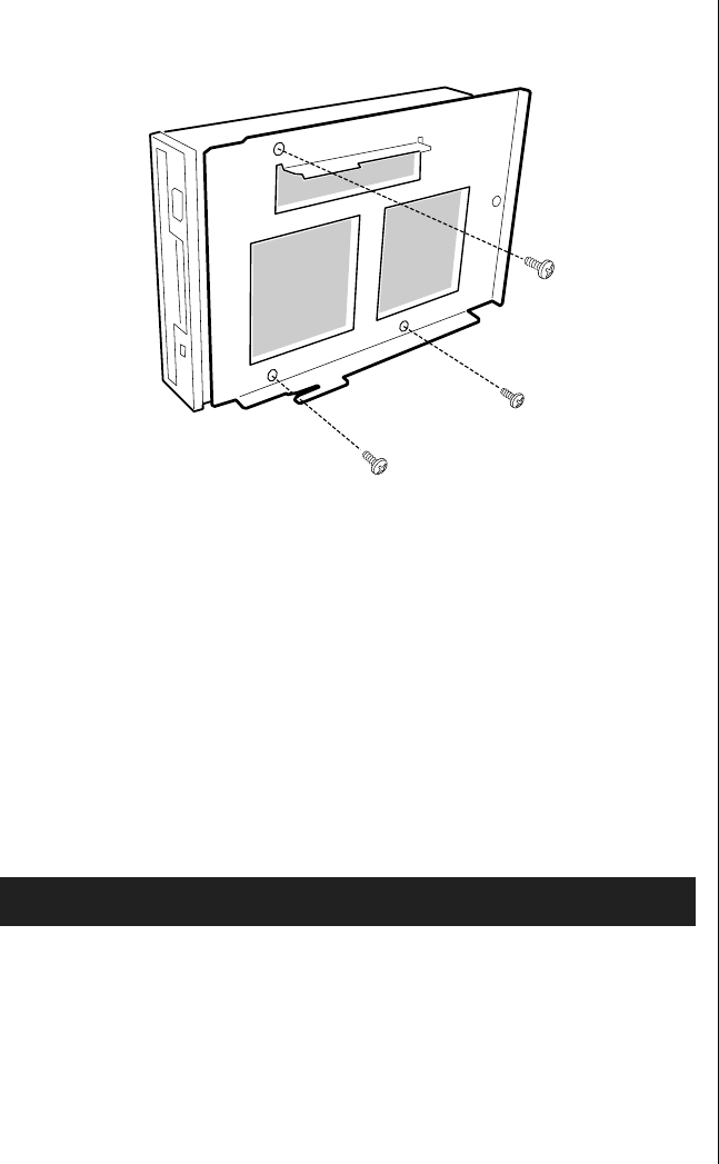
Installing Hardware 47
8. Remove the three screws that hold the carrier to the drive, and set them
and the carrier aside. See Figure 14.
Figure 14: Removing the Diskette Drive Carrier
9. Place the drive in an antistatic protective wrapper if you are not
reinstalling the same drive.
10. Reinstall the foam pads, fans (see “Installing an Individual System
Fan” on page 62) and the access cover using the original screws.
Installing the Diskette Drive
You should only replace the diskette drive if the originally installed drive
fails.
1. Remove the new 3.5-inch diskette drive from its protective wrapper,
and place it component-side up on an antistatic surface.
2. Set any jumpers or switches according to the drive manufacturer's
instructions.
3. Place the drive carrier on the component-side of the drive, and align
the three mounting holes.
To Install the Diskette Drive
3424.boo Page 47 Wednesday, September 2, 1998 9:23 AM

48 Maintaining and Troubleshooting the Gateway ALR 9200 Server
4. Attach the carrier to the drive with three screws of the appropriate size
and length (reuse the screws you removed before). Tighten the screws
firmly.
5. Position the carrier so that the two protruding notches fit into the
corresponding slits in the side of the 5.25-inch drive bay. Slide the
assembly toward the front of the system to engage the notches.
6. Make sure the front of the drive fits correctly in the front opening of
the system. When properly positioned, the carrier notches extend
slightly into the interior of the 5.25-inch drive bay and the threaded
hole in the carrier aligns with the threaded hole in the frame.
7. Secure the assembly to the 5.25-inch bay with the screw you removed
earlier; tighten the screw firmly.
8. Connect the signal and power cables to the drive. The red stripe on the
signal cable must face toward the center of the drive.
9. Reinstall the foam pads, fans (see “Installing an Individual System
Fan” on page 62) and the access cover using the original screws.
10. Run the SSU or BIOS Setup to specify that the diskette drive is
installed in the system (“Modifying Resources” on page 114 or “Main
Menu” on page 85).
Drive Cabling Considerations
Excluding the diskette drive, there are two types of devices that can be
installed in the server; IDE devices and SCSI devices. This section covers
cabling consideration for both types of devices. These cable considerations
apply to any devices using the IDE or narrow SCSI controllers.
The number of devices you can install depends on:
•The number supported by the bus
•The number of physical drive bays available
•The combination of SCSI and IDE devices
Note:
The 3.5-inch diskette drive is
not installed in the 5.25-inch
drive bay. The diskette drive
carrier attaches to the
outside of the 5.25-inch
drive bay (see Figure 13 on
page 46).
3424.boo Page 48 Wednesday, September 2, 1998 9:23 AM
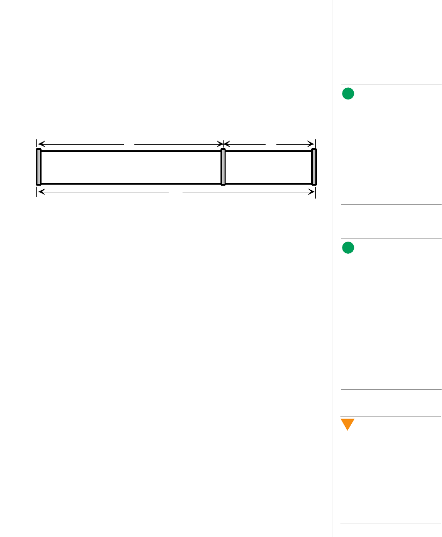
Installing Hardware 49
IDE Requirements
An 18-inch long IDE cable that supports two drives is standard in the
system. If you install an IDE hard drive, we recommend placing it in the
lowest internal drive bay to make cabling easier, particularly if you also
have an IDE device in the 5.25-inch drive bay.
For proper IDE operation, note the cable length specified in Figure 15. If no
drives are present on an IDE channel, the cable must be removed. If only
one drive is installed, it must be connected at the end of the cable.
Figure 15: IDE Cable Dimensions
SCSI Requirements
One wide SCSI cable is standard in the system, connecting the system
board to the SCSI backplane.
Terminate only the peripheral at the end of the SCSI cable. Hard drives
usually provide active termination, while SCSI CD-ROM drives do not.
Because we recommend putting hard drives only in the internal bays, you
should route the SCSI cable so that the last device on it is a hard drive in the
internal bay. The SCSI backplane in thew internal SCSI drive bay provides
active termination for the SCSI drives connected to the backplane.
In general, install legacy devices in the 5.25-inch drive bay and connect
them to the narrow SCSI cable. Ultra and Ultra-2 devices are normally hard
drives connect them to the SCSI backplane at the rear of the SCSI drive bay.
The wide SCSI connectors support either single-ended (SE) or low voltage
differential (LVD) drives.
Installing a 5.25-inch Peripheral in the Front Bay
Three 5.25-inch half-height bays provide space for tape backup, CD-ROM,
or other removable media drives.
Note:
If you disable the IDE
controller to reuse the
interrupt for that controller,
you must physically unplug
the IDE cable from the
system board. Simply
disabling the drive by
configuring the SSU option
does not free the interrupt.
12" 6"
18"
System
board Drive 1 Drive 0
Note:
It is important that the
cabling and connections
meet the SCSI bus
specification. Otherwise, the
bus may be unreliable and
data corruption may occur
or devices might not work at
all. You must terminate the
SCSI bus at the end of the
cable; the last device on the
cable usually provides bus
termination.
Caution!
We recommend that you do
not install hard drives in the
5.25-inch bays: the drives
cannot be properly cooled in
this location; also, a hard
drive generates EMI and is
therefore more susceptible
to ESD in this location.
3424.boo Page 49 Wednesday, September 2, 1998 9:23 AM
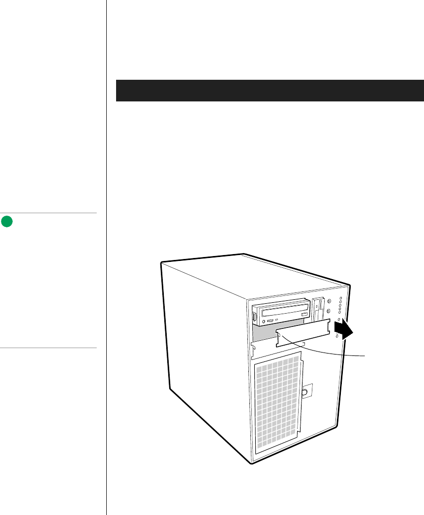
50 Maintaining and Troubleshooting the Gateway ALR 9200 Server
Either type of device (IDE or SCSI) can be installed in the 5.25-inch
peripheral bays. The system board only provides a single IDE cable and
therefore only supports two IDE devices. The single narrow SCSI
connector on the system board supports up to seven devices. The last device
on the SCSI bus must be terminated.
1. Observe the safety and ESD precautions in“Static Electricity
Precautions” on page 2. Also see the cabling considerations in “Drive
Cabling Considerations” on page 48.
2. Open the front door by rotating its right side out and to the left.
3. Remove the access cover, see “Opening the System” on page 3.
4. Push the tab (A in Figure 16) on the left side of the EMI metal shield
to the right to disengage it from the chassis. Removeand save the
shield.
Figure 16: Removing the EMI Shield
To Install a 5.25-inch Device
Note:
System EMI integrity and
cooling are both protected
by having drives installed in
the bays or filler panels and
EMI shields covering the
bays. When you install a
drive, save the panel and
shield to reinstall in case you
should later remove the
drive and not reinstall one in
the same bay.
Tab on EMI
metal shield
3424.boo Page 50 Wednesday, September 2, 1998 9:23 AM
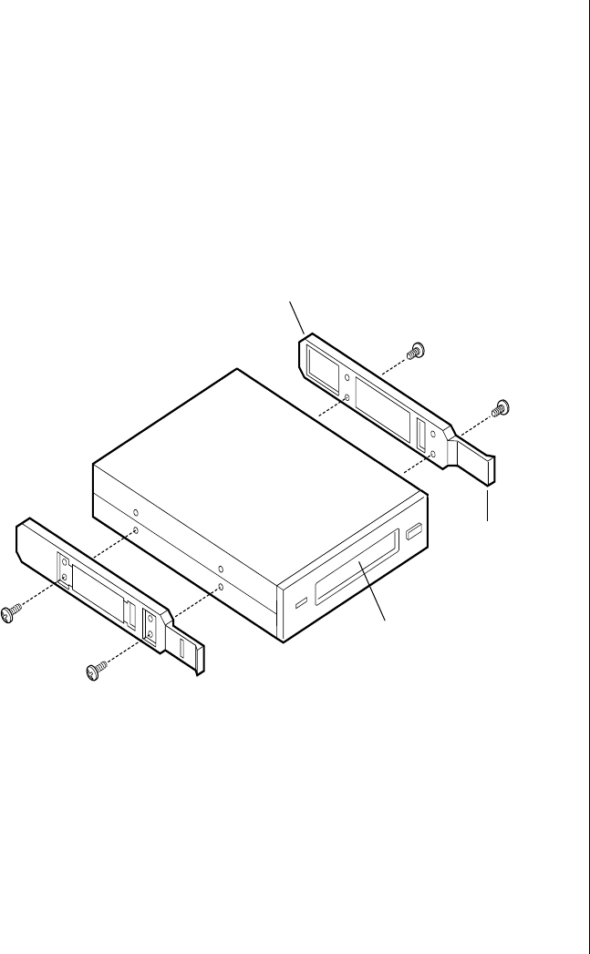
Installing Hardware 51
5. Open the subchassis (see “Opening the Subchassis and Electronics
Bay” on page 5) to gain access to the back of the 5.25-inch drive bay.
6. Remove the drive from its protective wrapper, and place it on an
antistatic surface.
7. Set any jumpers or switches on the drive according to the drive
manufacturer’s instructions.
8. Using two screws of the appropriate size and length (not supplied),
attach each plastic slide rail (see Figure 17) with its metal grounding
plate to the drive.
Figure 17: Attaching the Slide Rails
9. Position the drive so the plastic slide rails engage in the bay guide rails.
Push the drive into the bay until the slide rails lock in place.
10. Connect a power cable to the drive. The connectors are keyed and can
be inserted in only one way.
Slide rail
Tab on slide rail
Removable media device
3424.boo Page 51 Wednesday, September 2, 1998 9:23 AM

52 Maintaining and Troubleshooting the Gateway ALR 9200 Server
11. Connect a signal cable to the drive.
•SCSI drive: Attach connectors on the cable to the SCSI device or
devices you are installing.
•IDE drive: The system board has one IDE connector. It can
support an IDE signal cable up to 18 inches long. See Figure 15 on
page 49 for the cable dimensions.
12. If the drive requires any other cables, connect them.
13. Close the subchassis and make sure the foam cover is properly
installed, being careful not to pinch any wires or cables (see “Closing
the Subchassis and Electronics Bay” on page 7).
14. Replace the access cover, see “Closing the System” on page 7.
15. Close the front door.
Removing a 5.25-inch Peripheral from the Front Bay
If you remove a device from the 5.25-inch drive bay and do not replace it
with another 5.25-inch device of the same height, replace the EMI shield(s)
in the drive bay to maintain the EMI and airflow characteristics of the
chassis.
1. Observe the safety and ESD precautions in “Static Electricity
Precautions” on page 2.
2. Open the front door by rotating its right side out and to the left.
3. Remove the access panel, see “Opening the System” on page 3.
4. Open the subchassis (see “Opening the Subchassis and Electronics
Bay” on page 5) to gain access to the back of the 5.25-inch drive bay.
5. Disconnect the power and signal cables from the drive.
To Remove a 5.25-inch Device
Caution!
The internal narrow SCSI
interface in this system
supports only single-ended
SCSI devices. Connecting
differential SCSI drive types
to this interface can result in
electrical damage to the
system board and
peripherals.
3424.boo Page 52 Wednesday, September 2, 1998 9:23 AM
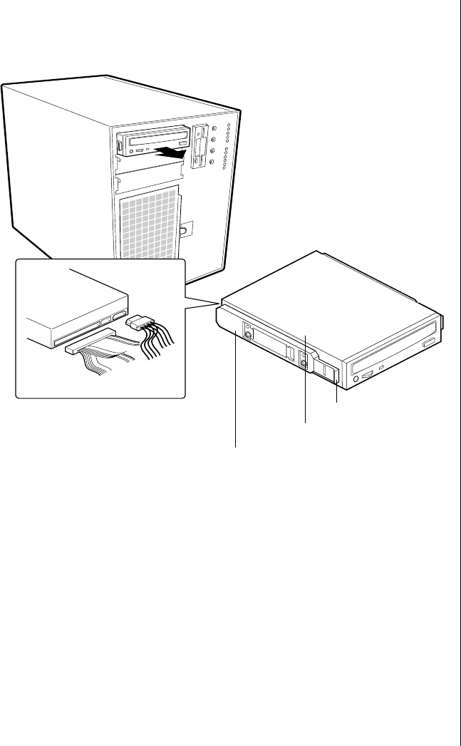
Installing Hardware 53
6. The drive has two protruding plastic, snap-in rails attached. Squeeze
the rail tabs toward each other as you carefully slide the drive forward
out of the bay, and place it on an antistatic surface (Figure 18).
Figure 18: Removing a Removable Media Device
7. Remove and save the four screws and two slide rails.
8. If you do not replace the device with another 5.25-inch device, replace
the EMI shields to maintain the EMI and airflow characteristics of the
chassis.
If the device is a SCSI device and it was installed at the end of the
SCSI signal cable, modify the cable and termination arrangement so
that a proper termination exists at the end of the cable (it can be a
termination device only, not necessarily a SCSI peripheral).
9. Close the subchassis and make sure the foam cover is properly
installed, being careful not to pinch any wires or cables (see “Closing
the Subchassis and Electronics Bay” on page 7).
Tab on slide rail
Removable media device
Slide rail
3424.boo Page 53 Wednesday, September 2, 1998 9:23 AM
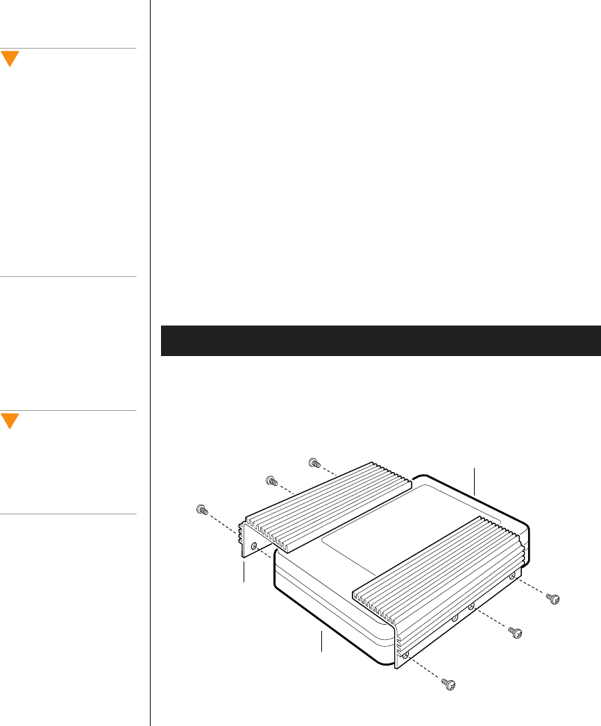
54 Maintaining and Troubleshooting the Gateway ALR 9200 Server
10. Replace the access panel, see “Closing the System” on page 7.
11. Close the front door.
SCSI Hard Disk Drives
The system supports a variety of SCSI devices. As shipped from the
supplier, the system might contain no hard disk drives. Contact your sales
representative or dealer for a list of approved SCSI devices. If you install
10,000 rpm SCSI hard drives, you must install heat sinks on the drives and
additional fans in the chassis. See the sections below for specific
instructions.
Installing Heatsinks on High-Power Drives
If you plan to use SCSI drives whose power exceeds 15 watts, you must
install heatsinks on those drives.
1. Position each heatsink (Figure 19) so that the three screw holes in the
heatsink align with the corresponding holes in the hard drive. The
holes are placed so that you can position the heatsink in only one way:
with the fins extending along the side and the top of the hard drive.
Figure 19: Installing Heatsinks on a Hard Drive
To Install Heatsinks on Hard Drives
Caution!
Electrostatic discharge
(ESD) can damage disk
drives and other
components. The server can
withstand normal levels of
ESD while you hot-swap
hard disk drives. Performing
all procedures in this manual
at an ESD-protected
workstation. If one is not
available, wear an antistatic
wrist strap attached to
chassis ground when
handling components.
Caution!
If you install high-power
drives, you must also install
additional system fans. See
“Installing Fans for High-
Power Drives” on page 57.
Hard drive, label side
Heat sink
Hard drive, component side
3424.boo Page 54 Wednesday, September 2, 1998 9:23 AM
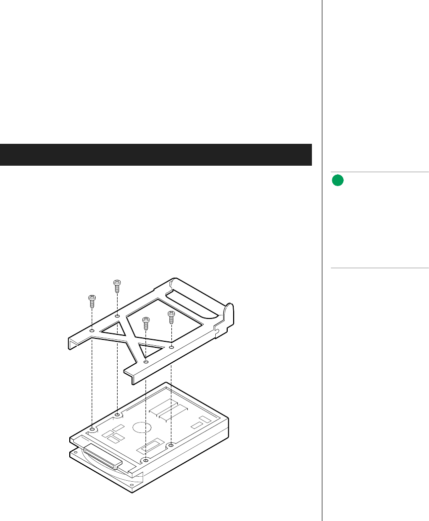
Installing Hardware 55
2. Use three screws (D) to attach each heatsink to the drive.
3. To insert the drive into the hot-docking bay, you must attach a carrier
to the drive. See “Mounting a SCSI Hard Disk Drive in a Carrier” on
page 55.
Mounting a SCSI Hard Disk Drive in a Carrier
Before you can install an LVD SCA-2 SCSI hard drive in the system, you
must mount it on a drive carrier to allow easy installation into the server.
1. Remove the 3.5-inch hard drive from its wrapper and place it on an
antistatic surface.
2. Orient the drive so the connector is near the top surface of the drive,
then place the carrier on top of the drive.
3. Using four screws of the correct size and length (not supplied), attach
the carrier to the drive (see Figure 20).
Figure 20: Hard Disk Drive and Carrier
To Mount a SCSI Drive on a Carrier
Note:
Faster drives, those
operating at or above
10,000 RPM, require the use
of aluminum drive carriers to
improve heat dissipation. Do
not mount these drives on
plastic carriers.
3424.boo Page 55 Wednesday, September 2, 1998 9:23 AM
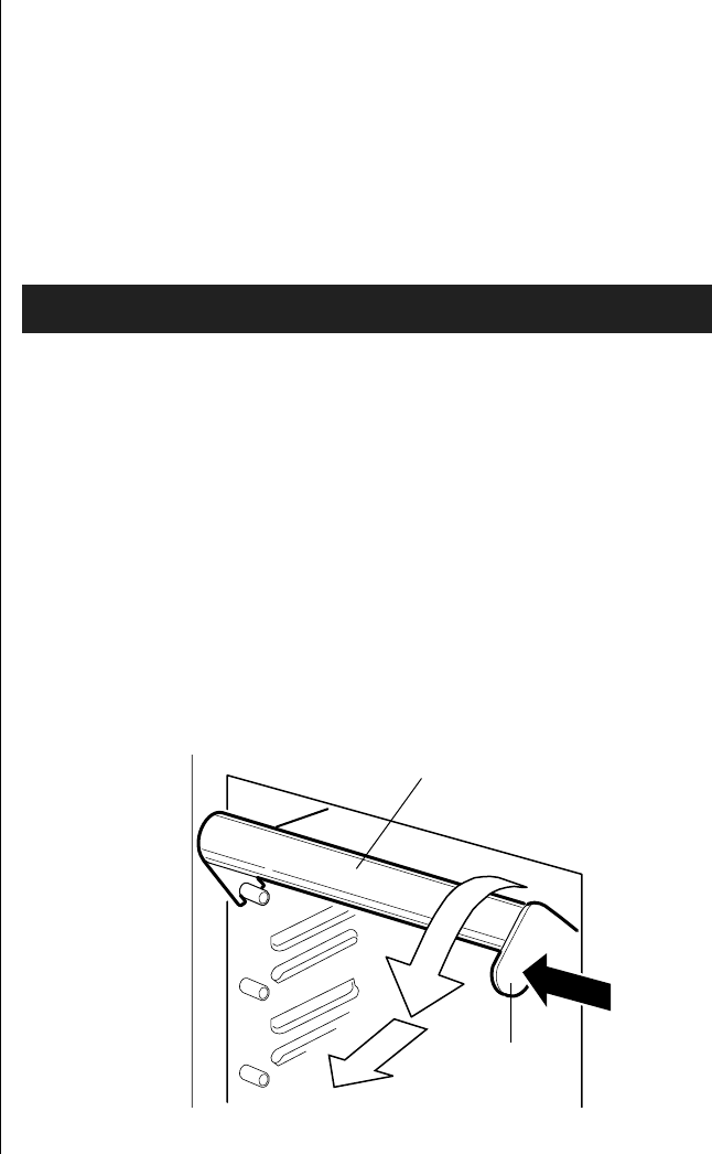
56 Maintaining and Troubleshooting the Gateway ALR 9200 Server
Hot-swapping a SCSI Drive
A bank of six yellow LEDs on the front panel monitors the drive status of
each drive in the hot-docking bay. Each LED corresponds directly to a
drive, so that the upper-most LED reflects an error condition in the upper-
most drive. The six LEDs and corresponding drives are numbered (top to
bottom) zero through five. When a yellow LED is on continuously, it is
okay to hot-swap (replace) a bad drive with a good one. You do not need to
shut the system down to hot-swap a drive.
1. Open the front system door by rotating its right side out and to the left.
2. If you installed a padlock on the metal door to the SCSI drive bay,
unlock the padlock and remove it.
3. Press the plastic latch securing the metal door to the SCSI drive cage,
and open the door.
4. Check the bank of yellow LEDs on the front panel to determine which
drive is bad.
5. Press the rounded tab on the right of the carrier to the left (toward the
center of the drive, Figure 21) while gently pulling straight down on
the carrier handle (Figure 21). This disengages the latch that secures
the carrier to the chassis.
Figure 21: Disengaging Drive Carrier from Chassis
To Hot-swap a SCSI Drive
Carrier handle
Tab
3424.boo Page 56 Wednesday, September 2, 1998 9:23 AM
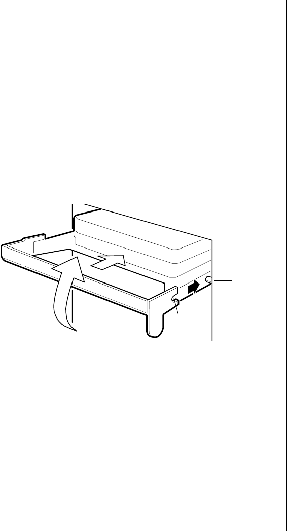
Installing Hardware 57
6. Grasp the plastic carrier handle and pull it toward you to disengage the
drive connector from the backplane connector.
7. Carefully slide the bad drive forward out of the bay. Place the drive on
an antistatic surface.
8. Position the new plastic carrier and drive assembly so that it engages
the bay guide rails.
9. Push the drive into the bay. To engage the latch, the carrier handle
should be approximately at a 45° angle from the vertical front of the
chassis. As you push the drive into the bay, the two rounded notches in
the carrier handle (Figure 22) slide onto the two round pegs inside the
drive bay . When they engage, push the handle straight up to lock the
notches onto the pegs and press the rounded tab on the right of the
carrier to the left until it clears the edge of the bay and snaps into place.
Figure 22: Installing a New Drive
10. Close the metal door, and secure it to the chassis with the plastic latch.
11. For security and to prevent unauthorized access to the bays, insert a
padlock through the metal loop protruding through the door.
12. Close the front system door.
Installing Fans for High-Power Drives
If the SCSI drives you use have a power rating in excess of 15 watts, install
three additional system fans: two in the front fan bay and one in the upper
power supply bay. Purchase the additional fans through normal channels.
Peg inside
drive bay
Notch on
carrier
handle
Carrier handle
3424.boo Page 57 Wednesday, September 2, 1998 9:23 AM
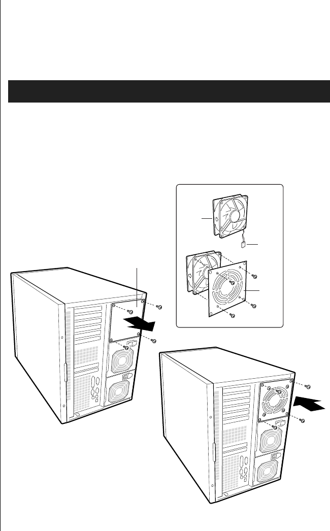
58 Maintaining and Troubleshooting the Gateway ALR 9200 Server
Installing a Fan in the Power Supply Bay
This procedure describes installation of a fan in the third power supply
module bay. This procedure is only valid for configurations using two
power supply modules.
1. Remove four screws, the grill plate, and fan from your kit.
2. Remove the plate (Figure 23) that covers the power supply bay closest
to the PCI slots. It is the uppermost bay when the server is standing
upright in pedestal mode.
Figure 23: Installing a Fan in the Power Supply Bay
To Install a Fan In the Power Supply Bay
Fan
Plate covering
power supply bay
Cable
Grill
plate
3424.boo Page 58 Wednesday, September 2, 1998 9:23 AM

Installing Hardware 59
3. Using four screws, attach the fan to the grill plate (Figure 23) so that
the fan label faces the plate.
4. Insert the fan/grill plate assembly into the power supply bay so that the
cable points downward (Figure 23) from the fan toward the other two
power supplies, and so the fan’s label faces out the back of the chassis.
This alignment is important to ensure correct airflow direction.
5. Using four screws, attach the fan/grill plate assembly to the chassis
(Figure 23).
Removing an Individual System Fan
The subchassis houses up to eight system fans. Not all of these fans are
required in standard configurations. If a fan fails, follow this procedure to
remove the failed fan.
1. Observe the safety and ESD precautions in “Static Electricity
Precautions” on page 2.
2. Remove the access cover (see “Removing the Access Cover” on
page 3).
To Remove an Individual System Fan
Note:
Correct airflow direction: The
side of each fan is
embossed with directional
arrows indicating airflow
direction. Always note the
direction of the arrows on a
fan before removing it. You
will need this information
later when you install a
different fan.
3424.boo Page 59 Wednesday, September 2, 1998 9:23 AM

60 Maintaining and Troubleshooting the Gateway ALR 9200 Server
3. Remove the foam cover from the front subchassis by pulling it straight
out (see Figure 24). Be careful not to break the foam.
Figure 24: Removing the System Fan Assembly
4. For better access to the individual fan cables on the front panel board,
carefully rotate the right edge of the foam fan assembly outward into
the opening where the foam cover was.
3424.boo Page 60 Wednesday, September 2, 1998 9:23 AM
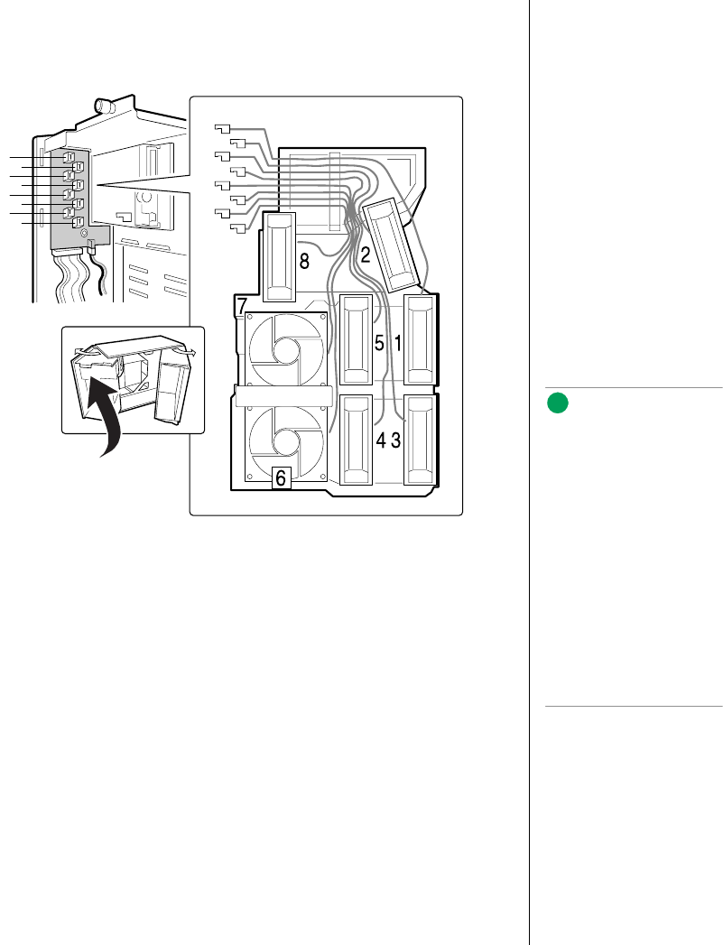
Installing Hardware 61
5. Label and disconnect the desired fan cable from the front panel board.
Be sure to note the position of the cable where it is held in place in the
foam fan assembly (see Figure 25).
Figure 25: Fan Cabling
6. Remove the fan cable from the foam assembly, being careful not to
break the foam.
7. Remove the fan from the foam assembly. All systems fans sit
differently in the assembly, but in general, each fan can slide in and out
of the foam in only one way.
1
3
5
7
2
4
6
81
1
7
5
32
4
6
8
Note:
The two installed fans
nearest the 5.25-inch drive
bays (fans 6 and 7 in
Figure 25) are separated by
a square piece of foam (the
piece with a crescent-
shaped hole) that extends
perpendicularly from the
front of the fans (in
Figure 25, it is the rectangle
between the round faces of
fans 6 and 7). You must
remove this piece to access
the two fans it separates
(pull it straight out).
3424.boo Page 61 Wednesday, September 2, 1998 9:23 AM

62 Maintaining and Troubleshooting the Gateway ALR 9200 Server
Installing an Individual System Fan
The subchassis houses up to eight system fans. Not all of these fans are
required in standard configurations. If you use high power hard drives, you
must install additional fans. Follow this procedure to install additional fans.
1. See “Removing an Individual System Fan” on page 59, as necessary.
2. Observe the safety and ESD precautions at the beginning this chapter.
3. Slide the fan into its correct receptacle in the foam fan assembly.
4. Attach the cable to the foam at the correct places (if you are replacing
a bad fan, you should have recorded where each cable attaches to the
foam; if you are adding a fan, see Figure 25 on page 61).
5. Position the fan assembly inside the chassis so that the individual fan
cables can easily reach their connectors on the front panel board.
6. Attach the cable to the front panel at the correct connector.
7. Position the fan assembly as it was inside the chassis prior to removal,
so that it rests firmly against the diskette drive at the top and the 5.25-
inch bays at the middle and bottom.
8. Reinstall the foam cover. It is molded to match the position of the fans
and fits in only one way.
9. Reinstall the access cover using the original screws.
Expansion Cards
The system board has seven slots for the installation of expansion cards.
There are six PCI slots and one shared slot that can support either a PCI
card or an ISA card.
To Install an Individual System Fan
Note:
The removable fan pulls air
from in front of the chassis
so that it flows across the
boards and out the back.
The fan must be oriented for
the correct airflow direction.
In general, the fan label is on
the side from which air exits
the fan. Confirm correct
orientation by checking the
embossed arrows on the
side of the fan:
⇒Arrow points horizontally
toward back of chassis
⇑Arrow points vertically up
Note the direction of the
arrows on the existing fan
before you remove it.
Replace a failed fan with the
same type as the one
removed.
Note:
If you install a PCI VGA video
card, you must install it in
one of the primary PCI slots.
3424.boo Page 62 Wednesday, September 2, 1998 9:23 AM
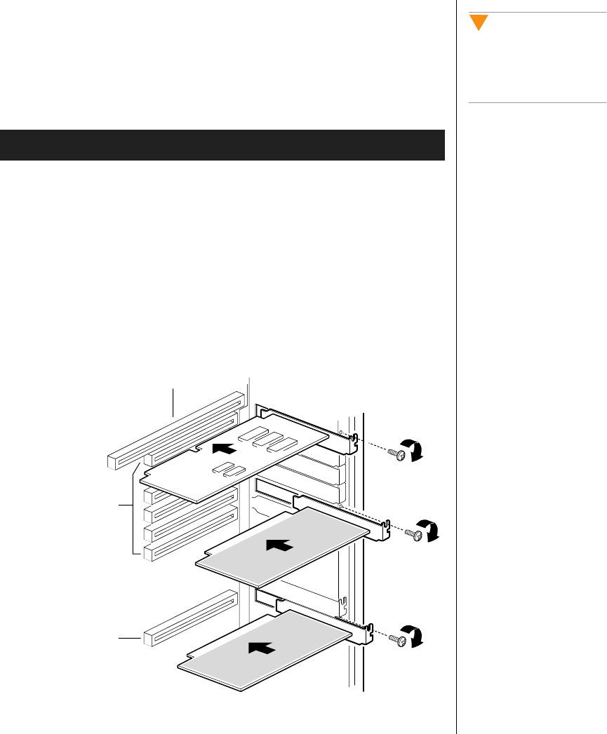
Installing Hardware 63
Installing an Expansion Card
Expansion cards can be extremely sensitive to ESD and require careful
handling. After removing the card from its protective wrapper or from the
system board, place it component-side up on a grounded, static-free surface
or conductive foam pad. Do not slide the card over any surface.
1. Remove the access panel (see “Removing the Access Cover” on
page 3).
2. Remove the expansion card from its protective wrapper. Be careful not
to touch the components or the gold edge connectors.
3. Set any jumpers or switches according to the manufacturer’s
instructions.
4. Remove the rear foam pad from the electronics bay.
5. Remove and save the expansion slot cover (Figure 26).
Figure 26: Installing an Expansion Card
To Install an Expansion Card
Caution!
Do not overload the system
board by installing
expansion cards that draw
excessive current.
ISA slot (use half length board only)
Six PCI slots (top to
bottom= PCI B3, B2,
B1, B0, A3, and A2)
PCI slot A1
3424.boo Page 63 Wednesday, September 2, 1998 9:23 AM

64 Maintaining and Troubleshooting the Gateway ALR 9200 Server
6. Hold the expansion card by its top edge or upper corners. Firmly press
it into an expansion slot on the system board. The tapered foot of the
board retaining bracket must fit into the mating slot in the expansion
slot frame.
a. Install an ISA board component-side up.
b. Install a PCI board component-side down.
7. Replace the screw you removed when you removed the slot cover to
secure the card in the slot.
8. Attach cables to the card if necessary.
9. Replace the rear foam pad.
10. Reinstall the access panel using the original screws (see “Installing the
Access Cover” on page 8).
11. Running the SSU is optional after you install or remove a PCI or ISA
board.
Removing an Expansion Card
Remember that removing an ISA expansion card may require you to use the
SSU to remove it from the system configuration.
1. Observe the safety and ESD precautions in “Static Electricity
Precautions” on page 2.
2. Remove the access cover (“Opening the System” on page 3), and the
rear foam pad.
3. Disconnect any cables attached to the board you are removing.
4. Remove and save the screw that secures the board in its slot.
5. Holding the board by its top edge or upper corners, carefully pull it
out. Do not scrape the board against other components.
6. Store the board in an antistatic protective wrapper.
To Remove an Expansion Card
Caution!
Slot covers must be installed
on all vacant expansion
slots. This maintains the
electromagnetic emissions
(EMI) characteristics of the
system and ensures proper
cooling of system
components.
3424.boo Page 64 Wednesday, September 2, 1998 9:23 AM
Installing Hardware 65
7. If you are not reinstalling a board in the same slot, install a slot cover
over the vacant slot. The tapered foot of the cover must fit into the
mating slot in the expansion slot frame.
8. Replace the rear foam pad and the access panel (“Closing the System”
on page 7).
9. Running the SSU is optional after you install or remove a PCI or ISA
board.
Power Supplies
The system can be configured with two or three power supply modules.
These configurations use a power share board that distributes the power
supplied by two supply modules to various system components. Table 5
shows the power distribution using the power share board. Configurations
using three power supply modules use the same power share board as those
using two supply modules. The third module acts as a hot spare and allows
hot swapping of failed power supply modules.
Table 5: Power Sharing
Power
Supply Output
B System board 5V
A System board 3.3V
A System board 12v-1
B System board 12V-2
A Peripheral 5V
B Peripheral 12V
Warning!
Hazardous voltage, current,
and energy levels are
present inside the power
supply. There are no
user-serviceable parts inside
it; servicing must be done by
technically qualified
personnel.
3424.boo Page 65 Wednesday, September 2, 1998 9:23 AM
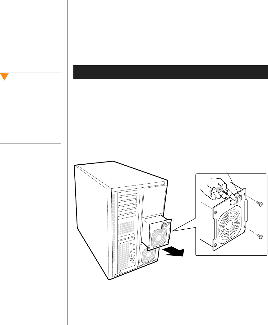
66 Maintaining and Troubleshooting the Gateway ALR 9200 Server
Removing a Power Supply Module
If the system configuration includes three power supply modules, hot-
swapping is possible; allowing you to remove a power supply module
without powering down the system. If your configuration uses only two
modules, you must power down the system before removing or replacing
the failed power supply module.
1. Disconnect the AC power cables from the power supply modules. You
must hold the power supply retention clip to the side as you remove the
power cord (see Figure 27 on page 66).
2. Remove the four screws (Figure 27) holding the power supply module
to the back of the chassis.
3. Using the flared, vertical edges as handles and using both hands, slide
the power supply module straight back from its bay (Figure 27).
Figure 27: Removing a Power Supply Module
Removing a Power Supply Module
Caution!
You might feel initial
resistance in sliding the
power supply from its bay.
Do not tilt or twist the
supply. Resistance is
caused by the supply
disengaging from its 40-pin
connector. Use even, steady
force to remove the supply.
Power supply module retention clip
3424.boo Page 66 Wednesday, September 2, 1998 9:23 AM

Installing Hardware 67
Installing a Power Supply Module
The power share board allows you to use two power supply modules or to
use two modules and install a third module as a hot backup. If you install
the third module, you can perform hot-swapping if a module fails.
1. If you have not already powered down the system or if you are not hot-
swapping the power supply module, power down the server.
2. If you are replacing a failed module, remove the failed module. See
“Removing a Power Supply Module” on page 66.
3. If you are installing an additional power supply module, remove the
access cover. If you are replacing a failed module, install the new
module in the same bay from which you removed the failed module.
4. Slide the power supply into its bay.
5. With even force on the flared, vertical edges, push toward the front of
the system until the edges rest against the rear of the chassis and the
power supply module engages its connector.
6. Install and tighten the four screws holding the module to the back of
the chassis.
7. Connect the AC power cable. You must slide the cover on the AC
connector to access the connector itself (Figure 27 on page 66).
Installing a Power Supply Module
3424.boo Page 67 Wednesday, September 2, 1998 9:23 AM
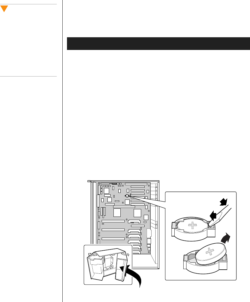
68 Maintaining and Troubleshooting the Gateway ALR 9200 Server
Replacing the Battery
The battery provides power for the system real-time clock and CMOS
RAM, which holds the system configuration information.
1. Restart the computer and start the BIOS Setup program by pressing F2
when you are prompted to do so.
2. Write down the CMOS values from BIOS Setup so you can reenter
them after you replace the battery. For more information about the
setup program, see “BIOS Setup” on page 79.
3. Turn off the system and disconnect the power cords.
4. Open the case, observing the static electricity precautions in “Static
Electricity Precautions” on page 2.
5. Locate the battery on the system board, see Figure 3 on page 11. The
battery is circular and has the positive pole mark (+) on the top.
6. Gently pull the battery from its socket. You may need to use a
screwdriver with an insulated handle or other implement to remove the
battery, see Figure 28.
Figure 28: Replacing the Battery
To Replace the Battery
Caution!
There is a danger of
explosion if the battery is
incorrectly replaced.
Replace the battery only
with the same or equivalent
type recommended by the
manufacturer. Dispose of
used batteries according to
the manufacturer’s
instructions.
3424.boo Page 68 Wednesday, September 2, 1998 9:23 AM

Installing Hardware 69
7. Press the new battery in the socket with the positive pole (+) up. Be
sure you have pressed the battery down far enough for it to contact the
base of the socket.
8. Close the case, as described in “Closing the System” on page 7.
9. Reconnect the power cord and turn on the system.
10. Enter the BIOS Setup program and verify that the system
configuration is correct using the data you recorded in Step 2.
If the CMOS data is not correct, change the information in the setup screens
as necessary.
Troubleshooting the Battery Installation
If you have problems after installing the new battery, try each of the items
listed below, replacing the cover and restarting the computer after each try.
•Turn off the system and ensure that all exterior cables are attached
to the correct connectors and secured.
•Check to be sure that all power switches are on. If the system is
plugged into a power strip or surge protector, be sure it is turned on
also.
•Enter the BIOS Setup program and compare the settings on the
screen with your notes or the system hardware manuals. Correct
any discrepancies.
•Turn off the system, remove the cover, and verify that all cables
inside the case are attached securely. Also, make sure that the
colored cable edges are aligned correctly and that the connectors
did not miss any pins. Disconnect and reconnect the cables, and
then replace the cover carefully so as not to disturb any cables.
•Turn off the system, remove the cover and, if you have the proper
test equipment, verify that the new battery has power. (It is
possible, although highly unlikely, that your new battery is
defective.)
If these procedures fail to correct the problem, contact technical support.
3424.boo Page 69 Wednesday, September 2, 1998 9:23 AM

70 Maintaining and Troubleshooting the Gateway ALR 9200 Server
3424.boo Page 70 Wednesday, September 2, 1998 9:23 AM

Chapter 4:
Jumpers and
Drivers
Contents
Setting the Jumpers................................................ 72
Changing a Jumper Setting ............................ 73
CMOS Clear Jumper...................................... 74
Password Clear Jumper.................................. 75
Recovery Boot Jumper................................... 75
Installing Software and Drivers ............................ 77
Installing Video Drivers................................. 77
3424.boo Page 71 Wednesday, September 2, 1998 9:23 AM
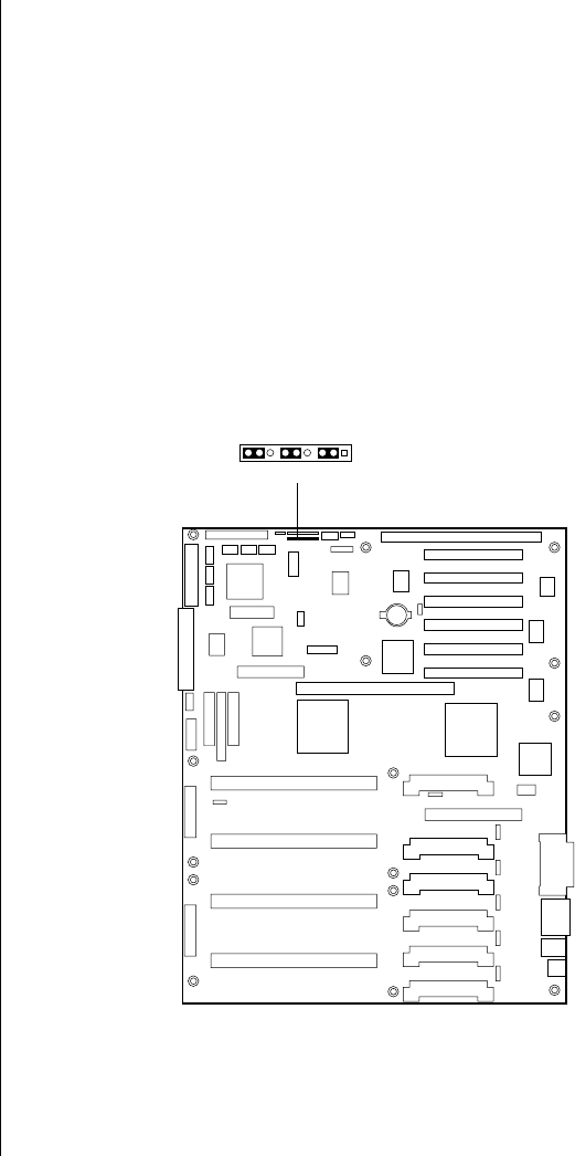
72 Maintaining and Troubleshooting the Gateway ALR 9200 Server
Setting the Jumpers
The system board jumpers let you change several system functions.
Jumpers are set to the default positions at the factory. You may need to
change the jumper settings to perform the following functions:
•Clear CMOS memory
•Clear the passwords from CMOS memory
•Recover from a failed BIOS update
One 11-pin connector provides three 3-pin jumper blocks that control the
functions identified above. Figure 29 shows the location and orientation of
the jumpers. Items in bold in Table 6 on page 73 show the default
placement for each configurable option.
Figure 29: System Board Jumpers
J6J1
13711 95
3424.boo Page 72 Wednesday, September 2, 1998 9:23 AM
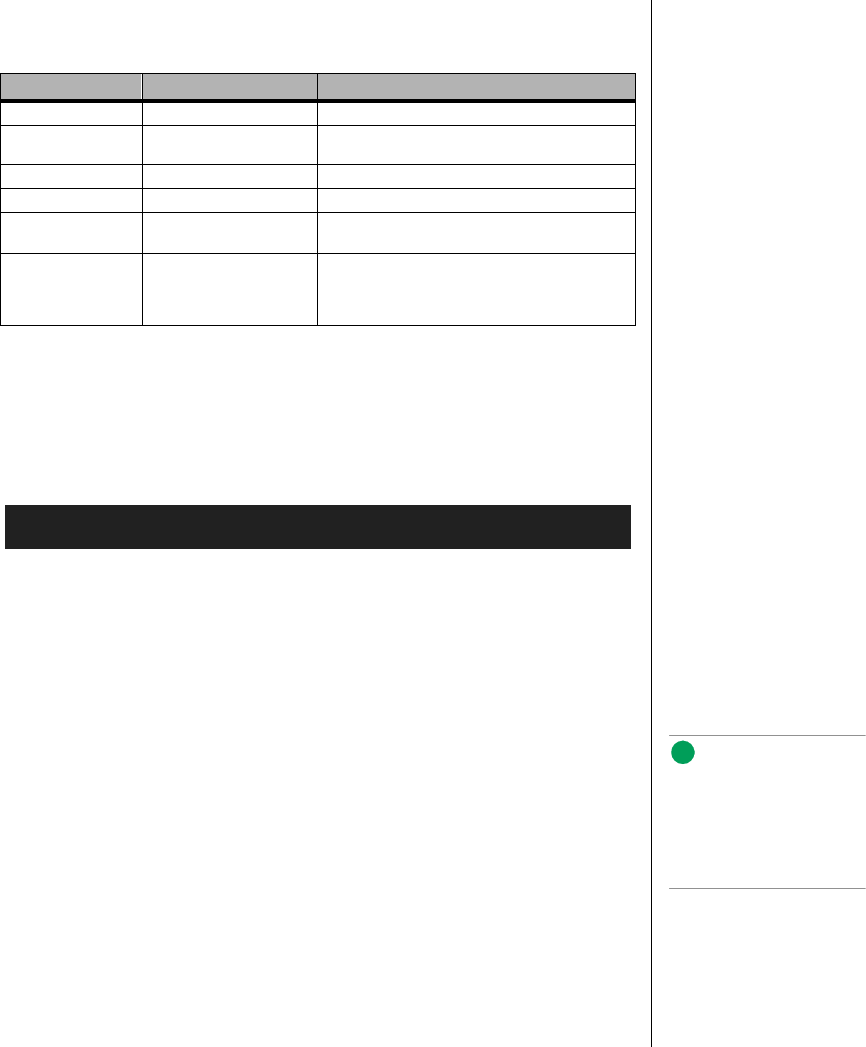
Setting the Jumpers 73
Changing a Jumper Setting
The short general procedure for changing a configuration setting is the
same for most of the jumper functions, so it is described here.
1. Observe the safety and ESD precautions at the beginning of “Static
Electricity Precautions” on page 2.
2. Turn off all connected peripherals, turn off system power, and
disconnect all AC power cords.
3. Remove the access cover.
4. Remove the foam insert from the electronics bay.
5. Locate the configuration jumpers at the edge of the system board
toward the front of the system (see Figure 29 on page 72).
6. Move the jumper to the pins specified for the desired setting.
7. Reinstall the foam insert and the access cover using the original
screws, connect the power cords, and turn on the system for the
change to take effect.
8. You may need to repeat these steps to move the jumper back to its
original setting, depending on the jumper function.
Table 6: System Board Jumper Summary
Function Pins What it Does at System Reset
CMOS clear 1-2, Normal Preserves the contents of the NVRAM
2-3, Forced erase Replaces the contents of the NVRAM with the
manufacturing default settings
Password clear 5-6, Protect Maintains the current passwords
6-7, Erase Clears the passwords
Recovery boot 9-10, Normal System boots using the BIOS stored in flash
memory
10-11, Recovery BIOS attempts a recovery boot, loading the BIOS
code from a diskette into the flash device. Use this
jumper when the BIOS code has been corrupted
by a failed flash update.
To Change a Jumper Setting
Note:
Y
ou do not need to remove
the system board from the
chassis, and you probably
do not need to remove any
expansion cards.
3424.boo Page 73 Wednesday, September 2, 1998 9:23 AM

74 Maintaining and Troubleshooting the Gateway ALR 9200 Server
CMOS Clear Jumper
The jumper at pins 1, 2, and 3 controls whether settings stored in CMOS
nonvolatile memory (NVRAM) are retained during a system reset.
1. See “Changing a Jumper Setting” on page 73.
2. Move the CMOS jumper from pins 1 and 2 to pins 2 and 3 (the Clear
CMOS memory position).
3. Reinstall the access cover for your safety (using the original screws),
and connect the power cords to the system.
4. Turn the system on. Wait for POST to complete and for the messages
NVRAM cleared by jumper
Press <F2> to enter Setup
to appear. This automatically reprograms CMOS to its default settings,
except for the password.
5. Enter Setup and make any changes necessary (for example, changing
the boot device).
6. Press F10 to save the new Setup configuration and exit Setup.
7. Turn off the system, and disconnect all AC power cords from the
system.
8. Again remove the access cover.
9. Move the jumper from pins 2 and 3 back to pins 1 and 2 (the Protect
CMOS memory position).
10. Reinstall the access cover using the original screws, and connect the
power cords to the system.
11. Run BIOS Setup or the SSU to verify the correct settings. See
Chapter 5, BIOS Setup and Chapter 6, The Server Setup Utility for more
information on setting BIOS and SSU fields.
To Restore the Manufacturing Default CMOS Settings
3424.boo Page 74 Wednesday, September 2, 1998 9:23 AM

Setting the Jumpers 75
Password Clear Jumper
The jumper at pins 5, 6, and 7 controls whether a stored password is
retained or cleared during a system reset.
1. See “Changing a Jumper Setting” on page 73.
2. Move the Password jumper from pins 5 and 6 to pins 6 and 7.
3. Reinstall the access cover for your safety (using the original screws),
and connect the power cords to the system.
4. Turn the system on, and wait for POST to complete. This
automatically clears the password.
5. Turn off the system, and disconnect all AC power cords.
6. Again remove the access cover.
7. Move the jumper from pins 6 and 7 back to pins 5 and 6.
8. Reinstall the access cover using the original screws, and connect the
power cords to the system.
9. Run the SSU to specify a new password. See “Security Add-in” on
page 116 for instructions on setting a password in the SSU.
Recovery Boot Jumper
The jumper at pins 9, 10, and 11 controls whether the system attempts to
boot using the BIOS programmed in flash memory or if it attempts to flash
the BIOS from a diskette in drive A. If an attempted BIOS update is
interrupted, you may need to perform this procedure.
1. See “Changing a Jumper Setting” on page 73.
2. Move the recovery boot jumper from pins 9 and 10 to pins 10 and 11.
To Clear and Replace a Password Using the Jumper
To Perform a Recovery Boot
3424.boo Page 75 Wednesday, September 2, 1998 9:23 AM
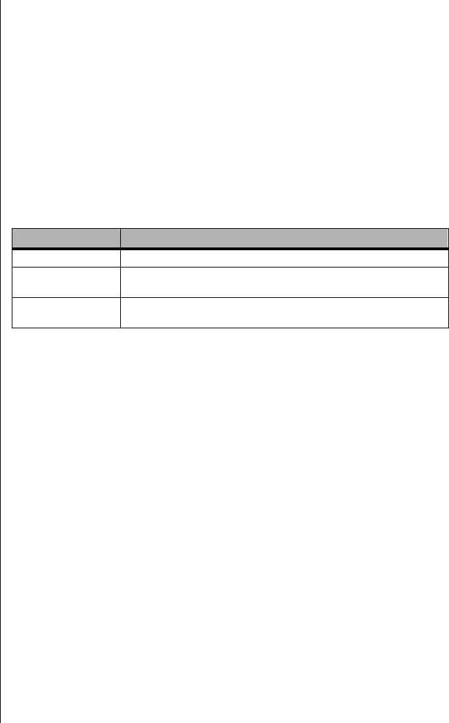
76 Maintaining and Troubleshooting the Gateway ALR 9200 Server
3. Reinstall the access cover for your safety (using the original screws),
then connect the power cords to the system.
4. Turn the system on, and insert the Flash Memory Update Utility
diskette in drive A. After the system boots, the speaker emits a single
beep and the recovery process starts. This takes about three minutes.
When the recovery process completes, the speaker emits two beeps.
While in recovery mode, there is no screen display on the monitor. The
keyboard is also disabled as the system automatically recovers the
BIOS. The beep codes listed in Table 7 describe the recovery status.
5. Turn the system off, disconnect all AC power cords from the system,
and remove the access cover.
6. Move the jumper from pins 10 and 11 back to pins 9 and 10 to enable
the normal boot mode.
7. Replace the foam pad and the access cover, remove the diskette from
drive A, and connect the power cords to the system.
8. After running the special recovery mode, run the BIOS Setup or the
SSU to specify a new password. See “Security Menu” on page 92 and
“Security Add-in” on page 116 for information on setting passwords
in BIOS Setup and the SSU.
Table 7: Recovery Boot Beep Codes
Beep Codes Message
2 Successful completion, no errors.
4 The system could not boot from the diskette. The diskette may not
be bootable.
Continuous series of
low beeps The wrong BIOS recovery files are being used and/or the flash
memory jumper is in the wrong position.
3424.boo Page 76 Wednesday, September 2, 1998 9:23 AM

Installing Software and Drivers 77
Installing Software and Drivers
Installing software and drivers is usually specific to the operating system
you run on the system. However, some tips on installing drivers or other
software in critical situations or under particular circumstances are provided
below.
Installing Video Drivers
After configuring the system, you need to install video drivers to take full
advantage of the features of the onboard CL-GD5480 super VGA video
controller.
•The software shipped with the server includes video drivers for use
with Windows NT.
•For other operating systems, see the operating system instructions
for installing device drivers.
Note:
If you install a PCI VGA video
card, you must install it in
one of the primary PCI slots.
3424.boo Page 77 Wednesday, September 2, 1998 9:23 AM

78 Maintaining and Troubleshooting the Gateway ALR 9200 Server
3424.boo Page 78 Wednesday, September 2, 1998 9:23 AM

Chapter 5:
BIOS Setup
Contents
Introduction............................................................ 80
Using BIOS Setup ................................................. 81
Record Your Setup Settings........................... 81
If You Cannot Access Setup.......................... 82
Starting Setup.................................................. 82
Setup Menus .......................................................... 83
Setup Key Commands.................................... 84
Special Display Items..................................... 84
Main Menu ..................................................... 85
Advanced Menu ............................................. 87
Security Menu ................................................ 92
Server Menu ................................................... 93
Boot Menu ...................................................... 95
Exit Menu ....................................................... 97
Upgrading the BIOS.............................................. 98
Preparing for the Upgrade.............................. 98
Upgrading the BIOS..................................... 100
Recovering the BIOS ................................... 101
Changing the BIOS Language..................... 101
3424.boo Page 79 Wednesday, September 2, 1998 9:23 AM

80 Maintaining and Troubleshooting the Gateway ALR 9200 Server
Introduction
This chapter describes the BIOS Setup utility. The following chapters
describe the power-on self test (POST) and other utilities for configuring
and managing the server. These utilities are:
•POST: described in Chapter 7, “Other Utilities” on page 125.
POST checks basic system integrity and all major components.
•Server Setup Utility (SSU): described in Chapter 6, “The Server
Setup Utility” on page 103. Use for extended system configuration
of onboard resources and expansion cards, viewing the system
event log (SEL), setting boot device priority, or setting system
security options.
Run the SSU from a set DOS-bootable diskettes. See “What You
Need to Do” on page 106 to make a set of SSU diskettes.
Information entered via the SSU overrides information entered via
Setup.
•Emergency Management Port (EMP) Console: described in
Chapter 7, “Other Utilities” on page 125. Use the EMP to access
and monitor the server remotely.
•FRUSDR Load Utility: described in Chapter 7, “Other Utilities”
on page 125. Use to update the Field Replacement Unit (FRU),
Sensor Data Record (SDR), and Desktop Management Interface
(DMI) flash components.
•BIOS Update Utility: described in Chapter 7, “Other Utilities” on
page 125. Use to update the BIOS or recover from a corrupted
BIOS update.
•Firmware Update Utility: described in Chapter 7, “Other Utilities”
on page 125. Use to update the BMC flash ROM.
•Symbios SCSI Utility: described in Chapter 7, “Other Utilities” on
page 125. Use to configure or view the settings of the SCSI host
adapters and onboard SCSI devices in the system.
If the system does not have a diskette drive, or the drive is disabled or
misconfigured, use Setup to enable it. Or, you can move the CMOS jumper
on the system board from the default setting (protect CMOS memory) to
the clear setting; doing so allows most system configurations to boot. Then
run BIOS Setup and the SSU to configure the system.
3424.boo Page 80 Wednesday, September 2, 1998 9:23 AM

Using BIOS Setup 81
Using BIOS Setup
This section describes the BIOS Setup options. Use Setup to change the
system configuration defaults. You can run Setup with or without an
operating system present. Setup stores most of the configuration values in
battery-backed CMOS; the rest of the values are stored in flash memory.
The values take effect when you boot the system. POST uses these values to
configure the hardware; if the values and the actual hardware do not agree,
POST generates an error message. You must then run Setup to specify the
correct configuration.
Run Setup: you can run Setup to modify any standard system board
feature such as:
•Select the diskette drive
•Select the parallel port
•Select a serial port
•Set the time or date (to be stored in the real-time clock (RTC))
•Configure an IDE hard drive
•Specify the boot device sequence
•Enable the SCSI BIOS
Run SSU, not Setup: you must run the SSU instead of Setup to do the
following:
•Enter or change information about an expansion card
•Alter system resources (e.g., interrupts, memory addresses, I/O
assignments) to your choices instead of those selected by the BIOS
resource manager
Record Your Setup Settings
It is a good idea to maintain a current record of the Setup and SSU settings
for each system. If the default values ever need to be restored (after a
CMOS clear, for example), you must run Setup again. Referring to your
notes will make the task easier.
3424.boo Page 81 Wednesday, September 2, 1998 9:23 AM

82 Maintaining and Troubleshooting the Gateway ALR 9200 Server
If You Cannot Access Setup
If the diskette drive is misconfigured so that you cannot access it to run a
utility from a diskette, you might need to clear CMOS memory. You must
open the system, change a jumper setting, use Setup to check and set
diskette drive options, and change the jumper back. For a step-by-step
procedure, see “CMOS Clear Jumper” on page 74.
Starting Setup
You can enter and start Setup under several conditions:
•When you turn on the system, after POST completes the memory
test
•When you reboot the system by pressing CTRL+ALT+DEL while at
the DOS operating system prompt
•When you have moved the CMOS jumper on the system board to
the “Clear CMOS” position (enabled); for a step-by-step
procedure, see “CMOS Clear Jumper” on page 74.
In the three conditions listed above, after rebooting, the system displays this
prompt:
Press <F2> to enter SETUP
In a fourth condition, when CMOS/NVRAM has been corrupted, the
system displays other prompts but not the F2 prompt:
Warning: cmos checksum invalid
Warning: cmos time and date not set
In this condition, the BIOS loads default values for CMOS and attempts to
boot.
3424.boo Page 82 Wednesday, September 2, 1998 9:23 AM

Setup Menus 83
Setup Menus
Setup has six major menus and several submenus. These menus are:
1. Main Menu
a. Primary IDE Master and Slave
b. Keyboard Features
2. Advanced Menu
a. PCI Configuration
• PCI Device, Embedded SCSI
• PCI Devices
b. I/O Device Configuration
c. Advanced Chipset Control
3. Security Menu
4. Server Menu
a. System Management
b. Console Redirection
5. Boot Menu
a. Boot Device Priority
b. Hard Drive
6. Exit Menu
3424.boo Page 83 Wednesday, September 2, 1998 9:23 AM
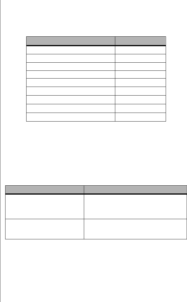
84 Maintaining and Troubleshooting the Gateway ALR 9200 Server
Setup Key Commands
Table 8 lists the keys commands available in Setup and what they do.
Special Display Items
Some items displayed on the screen do not behave as normal fields. These
items are either submenus or display-only fields. Table 9 provides more
information.
The rest of this section lists the features that display on screen after you
press F2 to enter Setup. Not all of the option choices are described, because
(1) a few are not user-selectable but are strictly informational, and (2) many
of the choices are relatively self-explanatory.
Table 8: Setup Key Commands
Function Key Command
Get general help F1 or ATL+H
Move between menus ← →
Go to the previous item ¦ (colon)
Go to the next Item Ø (zero)
Change the value of an item + or -
Select an item or display a submenu ENTER
Leave a submenu or exit Setup ESC
Reset to Setup defaults F9
Save and exit Setup F10
Table 9: Special Display Items
When you see this: It means this:
On screen, an option is shown but
you cannot select it or move to that
field.
You cannot change or configure the option in that
menu screen. Either the option is autoconfigured
or autodetected, or you must use a different Setup
screen, or you must use the SSU.
On screen, the phrase Press Enter
appears next to the option. Press ENTER to display a submenu that is either a
separate full-screen menu or a pop-up menu with
one or more choices.
3424.boo Page 84 Wednesday, September 2, 1998 9:23 AM
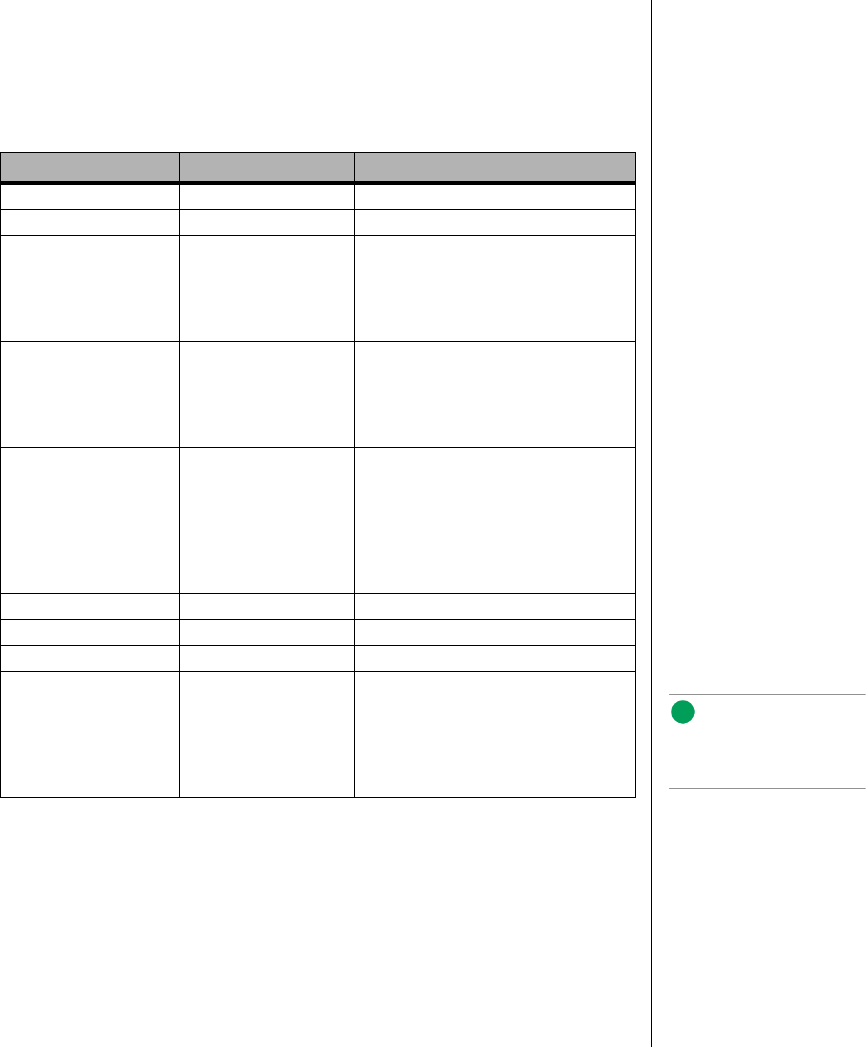
Setup Menus 85
Main Menu
Table 10 lists the selections you can make on the Main Menu itself. Use the
submenus for other selections. Default values are in bold.
Table 10: Main Menu
Field Options Description
System Time HH:MM:SS Sets the system time
System Date MM/DD/YYYY Sets the system date
Legacy Diskette A: Disabled
360 KB
720 KB
1.44 MB
2.88 MB
Selects the primary diskette type.
Legacy Diskette B: Disabled
360 KB
720 KB
1.44 MB
2.88 MB
Selects the secondary diskette type.
Hard Disk Pre-delay Disabled
3, 6, 9, 12, 15, 21, or
30 seconds
Adds a delay before the first BIOS
access of a hard disk drive. Some hard
disk drives hang if accessed before
they initialize themselves. This delay
ensures the hard disk drive has
initialized after powerup and before
being accessed.
Primary Master N/A Enters submenu.
Primary Slave N/A Enters submenu.
Keyboard Features N/A Enters submenu.
Language English (US)
Spanish
Italian
French
German
Japanese (Kanji)
Selects which language the BIOS
displays. Note:
Serial redirection does not
work with Kanji.
3424.boo Page 85 Wednesday, September 2, 1998 9:23 AM

86 Maintaining and Troubleshooting the Gateway ALR 9200 Server
Primary Master and Slave Submenu
In Table 11, the features other than “Type” appear only for Type Auto, if a
drive is detected.
Table 11: Primary IDE Master and Slave Submenu
Field Options Description
Type Auto
None
CD-ROM
IDE Removable
ATAPI Removable
User
Auto allows the system to attempt autodetection
of the drive type.
None informs the system to ignore this drive.
CD-ROM allows the manual entry of fields
described below.
User allows the manual entry of all fields described
below.
Cylinders 1 to 2048 Number of Cylinders on Drive.
This field is changeable only for Type User.
This field is strictly informational for Type Auto.
Heads 1 to 16 Number of read/write heads on drive.
This field is available only for Type User.
This field is strictly informational for Type Auto.
Sectors 1 to 64 Number of sectors per track.
This field is available only for Type User.
This field is strictly informational for Type Auto.
Maximum
Capacity N/A Computed size of drive from cylinders, heads, and
sectors entered.
This field is available only for Type User.
This field is strictly informational for Type Auto.
Multi-Sector
Transfers Disabled
2, 4, 8, or 16 sectors Determines the number of sectors per block for
multisector transfers.
This field is strictly informational for Type Auto.
LBA Mode
Control Disabled
Enabled Enabling LBA causes logical block addressing to
be used in place of cylinders, heads, and sectors.
This field is strictly informational for Type Auto.
32 Bit I/O Disabled
Enabled Enabling allows 32-bit IDE data transfers.
This field is strictly informational for Type Auto.
Transfer Mode Standard
Fast PIO 1
Fast PIO 2
Fast PIO 3
Fast PIO 4
Selects the method for moving data to and from
the drive.
This field is strictly informational for Type Auto.
Ultra DMA Disabled
Enabled For use with Ultra DMA drives.
This field is strictly information for Type Auto.
3424.boo Page 86 Wednesday, September 2, 1998 9:23 AM
Setup Menus 87
Keyboard Features Submenu
In Table 12, the settable features of the keyboard controller are listed along
with the options.
Advanced Menu
You can make the selections listed in Table 13 on the Advanced Menu
itself. Refer to “PCI Configuration Submenu” on page 88, “I/O Device
Configuration Submenu” on page 89, and “Advanced Chipset Control
Submenu” on page 91 for information on the three other selections that
appear on the Advanced Menu.
Table 12: Keyboard Features Submenu
Field Options Description
Num Lock Auto
On
Off
Selects the power on state for the
Num Lock key.
Key Click Disabled
Enabled Enables or disables key click.
Keyboard auto-
repeat rate 30, 26.7, 21.8, 18.5, 13.3, 10,
6, or 2 per second Selects the key repeat rate.
Keyboard auto-
repeat delay 1/4 sec
1/2 sec
3/4 sec
1 sec
Selects the delay before the keys
begin to repeat.
Table 13: Advanced Menu
Field Options Description
Plug and Play OS No
Yes Select Yes if you are booting a Plug and Play-
capable operating system.
Reset Configuration
Data No
Yes Select Yes if you want to clear the system
configuration data during the next boot. The
system automatically resets to No during the next
boot.
PCI Configuration N/A Enters submenu.
I/O Device Configuration N/A Enters submenu.
Use Multiprocessor
Specification 1.1
1.4 Selects the version of the multiprocessor
specification to use. Some operating systems
require version 1.1 for compatibility reasons.
3424.boo Page 87 Wednesday, September 2, 1998 9:23 AM
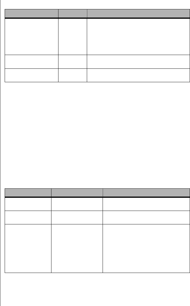
88 Maintaining and Troubleshooting the Gateway ALR 9200 Server
PCI Configuration Submenu
The PCI Configuration Menu contains selections that access other
submenus.
PCI Device, Embedded SCSI Submenu
This submenu provides three fields that allow you to control certain
characteristics of the embedded SCSI controllers. Table 14 lists the fields
and options.
Large Disk Access Mode LBA
CHS Applies to IDE drives only; refers to the method
used to access the drive.
Most operating systems use logical block
addressing (LBA); some use cylinder head sector
(CHS). To verify the correct method, consult the
operating system documentation.
Pause Before Boot Enabled
Disabled Enables a five-second pause before booting the
operating system.
Advanced Chipset
Control N/A Enters submenu.
Table 14: PCI Device, Embedded SCSI Submenu
Field Options Description
Option ROM Scan Enabled
Disabled Enables the option ROM scan of the
selected device.
Enable Master Disabled
Enabled Enables the selected device as a PCI bus
master.
Latency Timer Default
0020h
0040h
0060h
0080h
00A0h
00C0h
00E0h
Defines the minimum guaranteed time, in
units of PCI bus clocks, that a device can
be master on a PCI bus. Typically, option
ROM code overwrites the value set by the
BIOS.
Table 13: Advanced Menu (Continued)
Field Options Description
3424.boo Page 88 Wednesday, September 2, 1998 9:23 AM
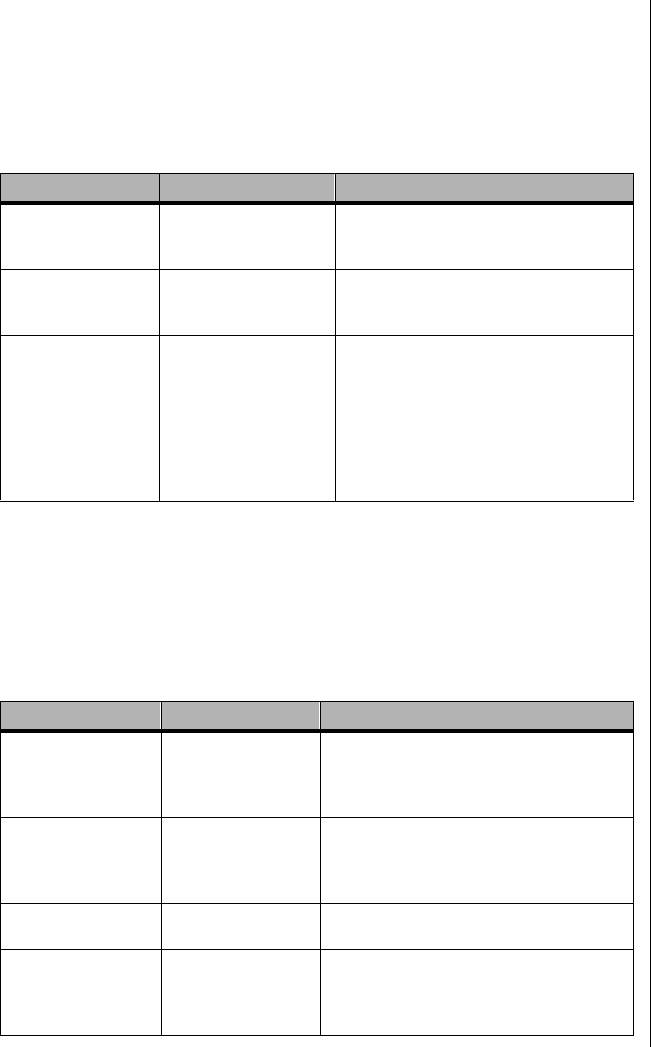
Setup Menus 89
PCI Devices Submenu
This submenu provides three fields that allow you to control certain
characteristics of the PCI expansion slots. Table 15 lists the fields and
options.
I/O Device Configuration Submenu
This submenu contains fields to control the I/O ports on the back panel of
the system. Table 16 lists the fields and the options available for each.
Table 15: PCI Devices Submenu
Field Options Description
Option ROM Scan Enabled
Disabled Enables the option ROM scan of all
devices other than the onboard SCSI
controllers.
Enable Master Disabled
Enabled Enables all devices, other than the
onboard SCSI controllers, as PCI bus
masters.
Latency Timer Default
0020h
0040h
0060h
0080h
00A0h
00C0h
00E0h
Defines the minimum guaranteed time, in
units of PCI bus clocks, that a device can
be master on a PCI bus. Typically, option
ROM code overwrites the value set by the
BIOS.
Table 16: I/O Device Configuration Submenu
Field Options Description
Serial Port A Disabled
Enabled
Auto
OS Controlled
Auto forces the BIOS to configure the port.
OS Controlled is shown when the operating
system controls the port.
Base I/O Address 3F8
2F8
3E8
2E8
Selects the base I/O address for COM port
A.
Interrupt IRQ 4
IRQ 3 Selects the IRQ for COM port A.
Serial Port B Disabled
Enabled
Auto
OS Controlled
Auto forces the BIOS to configure the port.
OS Controlled is shown when the operating
system controls the port.
3424.boo Page 89 Wednesday, September 2, 1998 9:23 AM

90 Maintaining and Troubleshooting the Gateway ALR 9200 Server
Mode Normal
IrDA
ASK-IR
Selects the mode for COM port B.
Base I/O Address 3F8
2F8
3E8
2E8
Selects the base I/O address for COM port
B.
Interrupt IRQ 4
IRQ 3 Selects the interrupt for COM port B.
Parallel Port Disabled
Enabled
Auto
OS Controlled
Auto forces the BIOS to configure the port.
OS Controlled is shown when the operating
system controls the port.
Mode ECP
Output only
Bidirectional
EPP
Selects the mode for the parallel port.
Base I/O Address 378
278 Selects the base I/O address for the parallel
port.
Interrupt IRQ 5
IRQ 7 Selects the interrupt for the parallel port.
DMA channel DMA 1
DMA 3 Selects the DMA channel for the parallel
port.
Floppy disk controller Disabled
Enabled Enables the onboard diskette controller.
Base I/O Address Primary
Secondary Sets the base I/O address for the diskette
controller.
PS/2 Mouse Auto
Disabled
Enabled
Enables or disables the onboard mouse.
Disabling the mouse frees IRQ 12. If this
feature is set to Auto or Enabled, the
operating system determines whether to
enable or disable the mouse.
Table 16: I/O Device Configuration Submenu (Continued)
Field Options Description
3424.boo Page 90 Wednesday, September 2, 1998 9:23 AM

Setup Menus 91
Advanced Chipset Control Submenu
The advanced chipset control submenu provides several fields that allow
you to control various advanced features of the chipset. Table 17 lists the
fields and the options for each.
Table 17: Advanced Chipset Control Submenu
Field Options Description
Address Bit
Permuting Disabled
Enabled To be enabled, there must be a power of 2 number
of rows (2, 4, 8, or 16), all rows must be the same
size, and all populated rows must be adjacent and
start at row 0. Two-way or four-way permuting is
set automatically based on memory configuration.
Base RAM Step 1 MB
1 KB
Every location
Tests base memory once per MB, once per KB, or
at every location.
Extended RAM
Step 1 MB
1 KB
Every location
Tests extended memory once per MB, once per
KB, or at every location.
L2 Cache Enabled
Disabled When enabled, the secondary cache is sized and
enabled. For Core Clock Frequency-to-System
Bus ratios equal to two, BIOS automatically
disables the L2 cache.
ISA Expansion
Aliasing Enabled
Disabled When enabled, every I/O access with an address in
the range x100-x3FFh, x500-x7FFh, x900-xBFF,
and xD00-xFFFh is internally aliased to the range
0100-03FFh before any other address range
checking is performed.
Memory Scrubbing Disabled
Enabled When enabled, BIOS automatically detects and
corrects single bit errors (SBEs).
Restreaming Buffer Enabled
Disabled When enabled, the data returned and buffered for
a Delayed Inbound Read can be reaccessed
following a disconnect.
Read Prefetch for
PXB0A N/A Informational field only. Configures the number of
Dwords that are prefetched on Memory Read
Multiple commands.
Read Prefetch for
PXB0B N/A Informational field only. Configures the number of
Dwords that are prefetched on Memory Read
Multiple commands.
3424.boo Page 91 Wednesday, September 2, 1998 9:23 AM

92 Maintaining and Troubleshooting the Gateway ALR 9200 Server
Security Menu
You can make the selections listed in Table 18 on the Security Menu.
Enabling the Supervisor Password field forces you to enter a password to
access Setup. Passwords are not case sensitive.
Table 18: Security Menu
Field Options Description
Administrator
Password is Clear
Set Status only. Once set, you can disable the
password by setting it to a null string (press
ENTER without typing any other characters) or by
clearing the password jumper on the system
board (see “Security Add-in” on page 116 ).
User Password is Clear
Set Status only. Once set, you can disable the
password by setting it to a null string or by
clearing the password jumper on the system
board (see “Security Add-in” on page 116).
Set Administrative
Password Press Enter When you press the ENTER key, you are
prompted for a password; press the ESC key to
cancel. Once set, you can disable the password
by setting it to a null string or by clearing the
password jumper on the system board (see
“Security Add-in” on page 116).
Set User Password Press Enter When you press the ENTER key, you are
prompted for a password; press the ESC key to
cancel. Once set, you can disable the password
by setting it to a null string or by clearing the
password jumper on the system board (see
“Security Add-in” on page 116).
Password on Boot Disabled
Enabled If enabled and the user password is set, the
system prompts you for a password before the
system boots.
Fixed Disk Boot
Sector Normal
Write Protect Write-protects the boot sector on the hard disk
to protect against viruses.
System Backup
Reminder Disabled
Daily
Weekly
Monthly
Displays the system-backup reminder message
at boot.
Virus Check
Reminder Disabled
Daily
Weekly
Monthly
Displays the virus-check reminder message at
boot.
Secure Mode Timer Disabled
1, 2, 5, 10,
or 20 min
1 or 2 hr
Defines the period of keyboard or PS/2 mouse
inactivity specified for secure mode to activate. A
password is required for secure mode to
function. This field cannot be enabled unless at
least one password is enabled.
3424.boo Page 92 Wednesday, September 2, 1998 9:23 AM
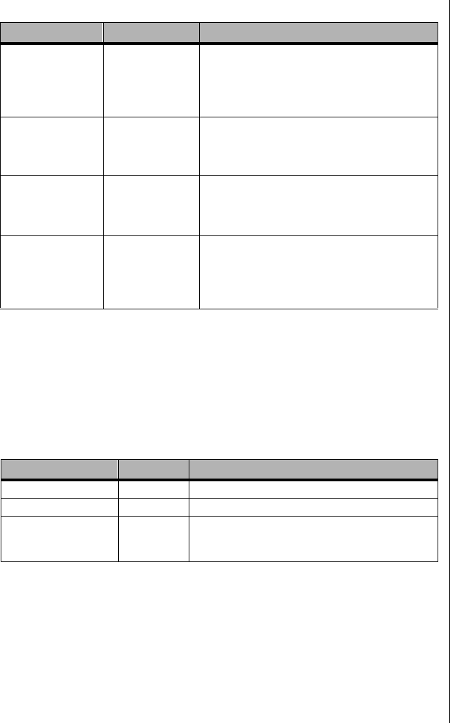
Setup Menus 93
Server Menu
The server menu contains three fields that allow you to perform server
specific management functions. Two of these fields open submenus.
Table 19 lists the fields and the options available for each.
Secure Mode Hot
Key (CTRL-ALT- ) [ ]
[A, B, ..., Z]
[0-9]
Defines the key assigned to invoke the secure
mode feature. You cannot enable this field
unless at least one password is enabled. Disable
this field by entering a new key followed by a
backspace or by pressing the DELETE key.
Secure Mode Boot Disabled
Enabled Causes the system to boot in secure mode. You
must enter a password to unlock the system.
You cannot enable this field unless at least one
password is enabled.
Video Blanking Disabled
Enabled Blanks the video when secure mode is activated.
You must enter a password to unlock the
system. You cannot enable this field unless at
least one password is enabled.
Floppy Write
Protect Disabled
Enabled When secure mode is activated, this field write
protects the diskette drive. You must enter a
password to reenable diskette writes. You
cannot enable this field unless at least one
password is enabled.
Table 19: Server Menu
Field Options Description
System Management N/A Enters submenu.
Console Redirection N/A Enters submenu.
Processor Retest No
Yes Instructs the BIOS to clear the historical processor
status and to retest all processors on the next
boot.
Table 18: Security Menu (Continued)
Field Options Description
3424.boo Page 93 Wednesday, September 2, 1998 9:23 AM

94 Maintaining and Troubleshooting the Gateway ALR 9200 Server
System Management Submenu
The system management submenu provides eight fields that allow you to
set system management characteristics. Table 20 lists the fields and the
options for each.
Console Redirection Submenu
The console redirection submenu provides four fields that allow you to
control the redirection of system management data to a remote console.
Table 21 lists the fields and the options for each.
Table 20: System Management Submenu
Field Options Description
Server
Management Mode Disabled
Enabled Enabled loads the Server Management Interrupt
handler, which handles system errors.
System Event
Logging Disabled
Enabled Enabled forces the BIOS and the BMC to log
system events.
Clear Event Log Disabled
Enabled Enabled clears the system event log.
Assert NMI on
AERR Disabled
Enabled Enabled generates a nonmaskable interrupt (NMI)
on an address parity error (AERR).
Assert NMI on
BERR Disabled
Enabled Enabled generates an NMI on a bus error (BERR).
Assert NMI on
PERR Disabled
Enabled Enabled generates an NMI on a parity error (PERR).
To activate this feature, the system error (SERR)
option must be enabled.
Assert NMI on
SERR Disabled
Enabled Enabled generates an NMI on a SERR.
Enabled Host Bus
Error Disabled
Enabled Enables host single-bit errors (SBEs) and multiple-
bit errors (MBEs).
Table 21: Console Redirection Submenu
Field Options Description
COM Port
Address Disabled
3F8
2F8
3E8
When enabled, console redirection uses the I/O
port specified.
When disabled, console redirection is
completely disabled.
IRQ # None, 3, or 4 When console redirection is enabled, this field
displays the IRQ assigned based on the
address chosen in the
COM Port Address
field.
3424.boo Page 94 Wednesday, September 2, 1998 9:23 AM
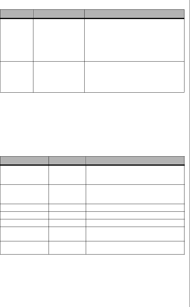
Setup Menus 95
Boot Menu
The boot menu contains seven fields that allow you to control the boot
process. Three of these fields open submenus. Table 22 lists the fields and
the options for each.
Baud Rate 9600
19.2k
38.4k
115.2k
When console redirection is enabled, this field
selects the baud rate.
When the Emergency Management Port (EMP)
shares the COM port as console redirection, the
baud rate must be set to 19.2k to match the
EMP baud rate, unless you use the autobaud
feature.
Flow Control No flow control
CTS/RTS
XON/XOFF
CTS/RTS + CD
None disallows flow control.
CTS/RTS is hardware flow control.
XON/XOFF is software flow control.
CTS/RTS +CD is hardware plus carrier-detect flow
control.
Table 22: Boot Menu
Field Options Description
Floppy Check Disabled
Enabled If Enabled, system verifies the diskette type on
boot.
Disabled results in a faster boot.
Multi-boot Support Disabled
Enabled This option should remain enabled unless you
install more than eight hard drives in the
system.
Boot Device Priority N/A Enters submenu.
Hard Drive N/A Enters submenu.
Removable Devices N/A Enters submenu.
Maximum Number of
I2O Drives 1
4Selects the maximum number of I2O drives
assigned a DOS drive letter.
Message Timeout
Multiplier 1, 2, 8, 10, 50,
100, 1000 All timeout values are multiplied by this number.
Table 21: Console Redirection Submenu (Continued)
Field Options Description
3424.boo Page 95 Wednesday, September 2, 1998 9:23 AM
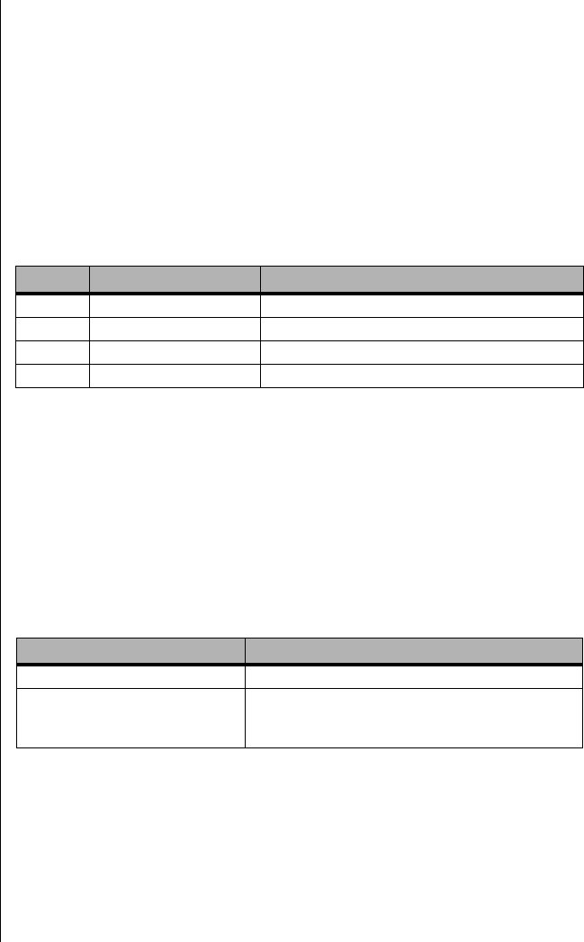
96 Maintaining and Troubleshooting the Gateway ALR 9200 Server
Boot Device Priority Submenu
The boot device priority submenu allows you to set the relative priority of
boot devices. The device identified as priority one is the first device
searched for boot data. If that device does not have boot data or is not ready,
the system looks for boot data on the second priority device and so on.
Use the up- or down-arrow keys to select a device. Press the + or - keys to
move the device higher or lower in the boot priority list. Table 23 shows the
structure of the boot device priority submenu.
Hard Drive Submenu
The hard drive submenu allows you to set the priority of the hard drives in
respect to the boot sequence. For options on this menu, use the up or down
arrow keys to select a device. Press the + or - keys to move the device higher
or lower in the boot priority list. Table 24 shows the manner in which the
drives are displayed.
Table 23: Boot Device Priority Submenu
Priority Device Description
1. Diskette drive Attempts to boot from drive A.
2. Removable devices Attempts to boot from a removable media device
3. Hard drive Attempts to boot from a hard drive.
4. ATAPI CD-ROM drive Attempts to boot from an ATAPI CD-ROM drive
Table 24: Hard Drive Submenu Boot Sequence
Option Description
1. Drive #1 (or actual drive string) N/A
2. Other bootable drives (additional
entries for each drive that has a
PnP header)
Covers all the boot devices that are not reported to
the system BIOS through the BIOS boot specification
mechanism.
3424.boo Page 96 Wednesday, September 2, 1998 9:23 AM

Setup Menus 97
Exit Menu
The exit menu provides four commands. Select an option using the up or
down arrow keys. Press ENTER to run the option. Pressing ESC does not exit
this menu. You must select one of the items from the menu or menu bar to
exit. Table 25 lists the options available and their functions.
Table 25: Exit Menu Command Options
Command Description
Exit Saving Changes Exits after writing all modified Setup item values to
NVRAM.
Exit Discarding Changes Exits leaving NVRAM unmodified and continues POST. You
are prompted if any of the Setup fields were modified.
Load Setup Defaults Loads the default values for all Setup items.
Load Custom Defaults Loads the settings from custom defaults.
3424.boo Page 97 Wednesday, September 2, 1998 9:23 AM

98 Maintaining and Troubleshooting the Gateway ALR 9200 Server
Upgrading the BIOS
Upgraded BIOS code is made available periodically. You should check the
website regularly, especially if you have a problem with the server that is
running BIOS Setup.
Preparing for the Upgrade
Before you upgrade the BIOS, prepare for the upgrade by recording the
current BIOS settings, obtaining the upgrade utility, and making a copy of
the current BIOS.
Recording the Current BIOS Settings
Remember to record the current BIOS settings. The upgrade process
should preserve most settings, but some options may no longer be available
or some options may change. Check the settings after the update to verify
that the current settings are correct.
1. Boot the computer and press F2 when you see the message:
Press <F2> Key if you want to run Setup
2. Write down the current settings from the BIOS Setup program.
Obtaining the Upgrade Utility
You can upgrade to a new version of the BIOS using the new BIOS files
and the BIOS upgrade utility, iFLASH.EXE. You can obtain the BIOS
upgrade file and the iFLASH.EXE utility through your computer supplier
or from the Intel World Wide Web site: http://www.intel.com.
This upgrade utility allows you to:
•Upgrade the BIOS in flash memory.
•Update the language section of the BIOS.
The following steps explain how to upgrade the BIOS.
To Record the Current BIOS Settings
Note:
Do not skip step 2. You will
need these settings to
configure your computer at
the end of the procedure.
Note:
Please review the
instructions distributed with
the upgrade utility before
attempting a BIOS upgrade.
3424.boo Page 98 Wednesday, September 2, 1998 9:23 AM

Upgrading the BIOS 99
Creating a Bootable Diskette
The upgrade process requires you to boot the server from the diskette drive.
You may need to redefine the boot sequence to set the diskette drive as the
first priority boot device.
1. Use a DOS or Windows 95 system to create the diskette.
2. Insert a diskette in drive A.
3. At the C:\ prompt, for an unformatted diskette, type:
format a:/s
or, for a formatted diskette, type:
sys a:
4. Press ENTER.
Creating the BIOS Upgrade Diskette
The BIOS upgrade file is a compressed self-extracting archive that contains
the files you need to upgrade the BIOS.
1. Copy the BIOS upgrade file to a temporary directory on your hard
disk.
2. From the C:\ prompt, change to the temporary directory.
3. To extract the file, type the name of the BIOS upgrade file, for
example:
10006BI1.EXE
4. Press ENTER. The extracted file contains the following files:
LICENSE.TXT
README.TXT
BIOS.EXE
To Create a Bootable Diskette
To Create the BIOS Upgrade Diskette
3424.boo Page 99 Wednesday, September 2, 1998 9:23 AM

100 Maintaining and Troubleshooting the Gateway ALR 9200 Server
5. Read the LICENSE.TXT file, which contains the software license
agreement, and the README.TXT file, which contains the
instructions for the BIOS upgrade.
6. Insert the bootable diskette into drive A.
7. To extract the BIOS.EXE file to the diskette, change to the temporary
directory that holds the BIOS.EXE file and type:
BIOS A:
8. Press ENTER.
9. The diskette now holds the BIOS upgrade and recovery files.
Upgrading the BIOS
The BIOS upgrade takes the server out of commission for a short time.
Make sure that there are no running processes or other critical activities
ongoing at the time you begin the BIOS upgrade.
1. Boot the server with the diskette in drive A. The BIOS upgrade utility
screen appears.
2. Select Update Flash Memory From a File.
3. Select Update System BIOS. Press ENTER.
4. Use the arrow keys to select the correct .bio file. Press ENTER.
5. When the utility asks for confirmation that you want to flash the new
BIOS into memory, select Continue with Programming. Press ENTER.
6. When the utility displays the message that the upgrade is complete,
remove the diskette. Press ENTER.
7. Reboot the server. As the server boots, check the BIOS identifier
(version number) to verify that the upgrade was successful.
8. To enter the Setup program, press F2 when you see the message:
Press <F2> Key if you want to run SETUP
To Upgrade the BIOS
3424.boo Page 100 Wednesday, September 2, 1998 9:23 AM

Upgrading the BIOS 101
9. For proper operation, load the Setup program defaults. To load the
defaults, press F9.
10. To accept the defaults, press ENTER.
11. Set the options in the Setup program to the settings you wrote down
before the BIOS upgrade.
12. To save the settings, press F10.
13. To accept the settings, press ENTER.
14. Turn off the computer and reboot.
Recovering the BIOS
It is unlikely that anything will interrupt the BIOS upgrade; however, if an
interruption occurs, the BIOS may be damaged. In that case, you must
recover the BIOS.
The procedure for recovering the BIOS is detailed in “Recovery Boot
Jumper” on page 75. After performing the procedure, leave the upgrade
disk in drive A and turn on the server, then continue with the BIOS upgrade
(see “Upgrading the BIOS” on page 98).
Changing the BIOS Language
You can use the BIOS upgrade utility to change the language the BIOS
displays. Use a bootable diskette containing the flash utility and language
files (see “Creating the BIOS Upgrade Diskette” on page 99).
1. Boot the computer with the bootable diskette in drive A. The BIOS
upgrade utility screen appears.
2. Select Update Flash Memory From a File.
3. Select Update Language Set. Press ENTER.
4. Select drive A and use the arrow keys to select the correct .lng file.
Press ENTER.
To Change the BIOS Language
Note:
Because of the small
amount of code available in
the nonerasable boot block
area, there is no video
support. You will see nothing
on the screen during the
procedure. Monitor the
procedure by listening to the
speaker and looking at the
diskette drive LED.
3424.boo Page 101 Wednesday, September 2, 1998 9:23 AM

102 Maintaining and Troubleshooting the Gateway ALR 9200 Server
5. When the utility asks for confirmation that you want to flash the new
language into memory, select Continue with Programming. Press ENTER.
6. When the utility displays the message upgrade is complete, remove
the diskette. Press ENTER.
7. Reboot the computer and the changes will take effect.
3424.boo Page 102 Wednesday, September 2, 1998 9:23 AM

Chapter 6:
The Server
Setup Utility
Contents
Introduction...................................................................104
Using the System Setup Utility....................................105
When to Run the SSU...........................................105
What You Need to Do ..........................................106
Running the SSU ..........................................................107
Running the SSU Locally.....................................107
Running the SSU Remotely .................................107
Starting the SSU....................................................108
Customizing the SSU ...................................................109
Launching a Task..........................................................111
Resource Configuration Add-in Window....................112
Using the RCA Window.......................................112
Defining an ISA Board.........................................113
Adding and Removing ISA Boards .....................114
Modifying Resources............................................114
System Resource Usage .......................................115
Multiboot Options Add-in............................................115
Security Add-in.............................................................116
Security Options....................................................117
System Event Log Viewer Add-in...............................118
Sensor Data Record Manager Add-In..........................120
Field Replaceable Unit Manager Add-In.....................122
Exiting the SSU.............................................................124
3424.boo Page 103 Wednesday, September 2, 1998 9:23 AM

104 Maintaining and Troubleshooting the Gateway ALR 9200 Server
Introduction
This chapter describes the Power-on Self Test (POST) and system
configuration utilities. These utilities are:
•BIOS Setup: described in Chapter 5, “BIOS Setup” on page 79. If
the system does not have a diskette drive, or the drive is disabled or
misconfigured, use Setup to enable it.
Or, you can move the CMOS jumper on the system board from the
default setting (Protect CMOS memory) to the Clear setting; doing
so allows most system configurations to boot. Then run the SSU to
configure the system.
•POST: described in Chapter 7, “Other Utilities” on page 125.
POST checks basic system integrity and all major components.
•Emergency Management Port (EMP) Console: described in
Chapter 7, “Other Utilities” on page 125. Use the EMP to access
and monitor the server remotely.
•FRUSDR Load Utility: described in Chapter 7, “Other Utilities”
on page 125. Use to update the Field Replacement Unit (FRU),
Sensor Data Record (SDR), and Desktop Management Interface
(DMI) flash components.
•BIOS Update Utility: described in Chapter 7, “Other Utilities” on
page 125. Use to update the BIOS or recover from a corrupted
BIOS update.
•Firmware Update Utility: described in Chapter 7, “Other Utilities”
on page 125. Use to update the BMC flash ROM.
•Symbios SCSI Utility: described in Chapter 7, “Other Utilities” on
page 125. Use to configure or view the settings of the SCSI host
adapters and onboard SCSI devices in the system.
Use the SSU for extended system configuration of onboard resources and
expansion cards, viewing the system event log (SEL), setting boot device
priority, or setting system security options.
Run the SSU from a set DOS-bootable diskettes. See “What You Need to
Do” on page 106 to make a set of SSU diskettes.
Information entered via the SSU overrides information entered via Setup.
3424.boo Page 104 Wednesday, September 2, 1998 9:23 AM

Using the System Setup Utility 105
Using the System Setup Utility
The system setup utility (SSU) is provided on a set of diskettes shipped
with the server. The SSU provides a graphical user interface (GUI) over an
extensible framework for server configuration. The SSU framework
supports the following functions and capabilities:
•Assigns resources to system board devices and expansion cards
before loading the operating system
•Lets you specify boot device order and system security options
•Permits viewing and clearing of the system event log (SEL)
•Permits viewing of the system field replaceable units (FRUs) and
sensor data record (SDR).
•Allows troubleshooting of the server when the operating system is
not operational
•Provides a system-level view of the server I/O devices
When to Run the SSU
The SSU is a DOS-based utility that supports extended system
configuration operations for onboard resources and expansion cards. Use
the SSU when you need to:
•Add and remove boards affecting the assignment of resources
(ports, memory, IRQs, DMA)
•Modify the server boot device order or security settings
•Change the server configuration settings
•Save the server configuration
•View or clear the system event log (SEL)
•View FRU information
•View the SDR table
If you install or remove an ISA expansion card, you must run the SSU to
reconfigure the server. Running the SSU is optional for PCI and Plug and
Play ISA expansion cards.
3424.boo Page 105 Wednesday, September 2, 1998 9:23 AM

106 Maintaining and Troubleshooting the Gateway ALR 9200 Server
The SSU is PCI-aware and complies with the ISA Plug and Play
specification; it works with any compliant configuration (.CFG) files
supplied by the peripheral device manufacturer.
The system board comes with a .CFG file describing the characteristics of
the board and the system resources it requires. The configuration registers
on PCI and ISA Plug and Play expansion cards contain the same type of
information in a .CFG file. Some ISA boards also come with a .CFG file.
The SSU uses the information provided by .CFG files, configuration
registers, flash memory, and the information that you enter, to specify a
system configuration. The SSU then writes the configuration information
to flash memory.
The configuration values in flash memory take effect when you boot the
server. POST checks the values against the actual hardware configuration;
if the values do not agree, POST generates an error message. You must then
run the SSU to specify the correct configuration before the server boots.
The SSU always includes a checksum with the configuration data so the
BIOS can detect any potential data corruption before the actual hardware
configuration takes place.
What You Need to Do
You must run the SSU from a set of DOS diskettes. You must follow the
instructions in the included README.TXT file to prepare the diskettes.
If your diskette drive is disabled or improperly configured, you must use the
flash-resident Setup utility to enable it so you can use the SSU. If necessary,
disable the drive after exiting the SSU. Information entered using the SSU
overrides any entered using Setup.
3424.boo Page 106 Wednesday, September 2, 1998 9:23 AM

Running the SSU 107
Running the SSU
The SSU can be run either locally (directly on the server you are
configuring) or remotely (on a workstation connected to the server you are
configuring through the network).
Running the SSU Locally
Running the SSU.BAT file starts the SSU. If the server boots directly from
the SSU media, the SSU.BAT file runs automatically. If the server boots
from different media, the SSU can be started manually or by another
application. When the utility starts in the local execution mode (the default
mode), the SSU accepts input from the keyboard and/or mouse. The SSU
provides a VGA-based GUI on the primary monitor.
The SSU runs from writable, nonwritable, removable, and nonremovable
media. If the SSU is run from nonwritable media, user preference settings
(like screen colors) cannot be saved.
The SSU supports the ROM-DOS V6.22 operating system. It can run on
other ROM-DOS compatible operating systems, but they are not supported.
The SSU will not operate from a “DOS window” running under an
operating system like Windows.
Running the SSU Remotely
To run the SSU remotely, you must invoke the SSU.BAT file with the /t
switch and redirect the text-mode output via BIOS console redirect. See
“Console Redirection Submenu” on page 94 for instructions on setting up
the remote console.
3424.boo Page 107 Wednesday, September 2, 1998 9:23 AM

108 Maintaining and Troubleshooting the Gateway ALR 9200 Server
Starting the SSU
The SSU is a collection of task-oriented modules plugged into a common
framework called the Application Framework (AF). The AF provides a
launching point for individual tasks and a location for setting customization
information.
1. Turn on the video monitor and the system.
2. Start the SSU by inserting the bootable SSU diskette into drive A.
Press the reset button or CTRL+ALT+DEL to reboot. When prompted to
do so, press F2 to enter the BIOS Setup. From the boot menu, select
the Boot Device Priority option. Select diskette drive as your primary
boot device. Save those settings and exit the BIOS Setup. The server
will boot from the diskette drive and display a menu of options. Follow
the instructions in the menu to start the SSU.
3. When the SSU title appears on the screen, press ENTER to continue.
4. The mouse driver loads if it is available; press ENTER to continue.
This message appears:
Please wait while the Application Framework loads....
When the main window of the SSU appears (Figure 30), you can
customize the user interface (UI) before continuing. See “Customizing
the SSU” on page 109.
To Start the SSU
3424.boo Page 108 Wednesday, September 2, 1998 9:23 AM
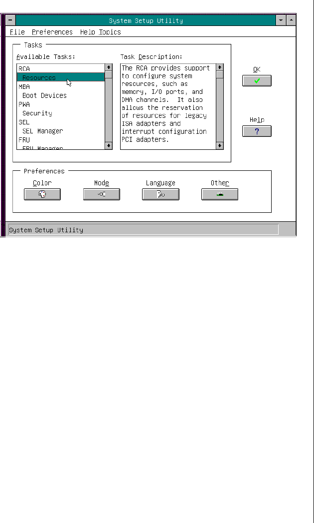
Customizing the SSU 109
Figure 30: SSU Main Window
Customizing the SSU
You can customize the UI according to your preferences. The AF sets these
preferences and saves them in the AF.INI file so that they take effect the
next time you start the SSU. Use these four user-customizable settings:
•Color—lets you change the default colors associated with
different items on the screen to predefined color combinations.
The changes are instantaneous.
•Mode—lets you set the desired expertise level.
•Novice
• Intermediate
• Expert
3424.boo Page 109 Wednesday, September 2, 1998 9:23 AM

110 Maintaining and Troubleshooting the Gateway ALR 9200 Server
The expertise level determines which tasks are visible in the
Available Tasks section and what actions each task performs. For a
new mode setting to take effect, you must exit the SSU and restart
it. In the current implementation, there is no distinction between
these three different modes.
•Language—lets you change the strings in the SSU to the
appropriate language. For a new language setting to take effect,
you must exit the SSU and restart it.
•Other—lets you change other miscellaneous options in the SSU.
The changes are instantaneous.
•Use the mouse to click on the proper button in the Preferences
section of the SSU Main window.
OR
•Use the tab and arrow keys to highlight the desired button, and
press the spacebar or ENTER.
OR
•Access the menu bar with the mouse or hot keys (ALT + the
underlined letter).
To Change the Interface Default Values
Note:
If you run the SSU from
nonwritable media (like a
CD-ROM), these
preferences are lost when
you exit the SSU.
3424.boo Page 110 Wednesday, September 2, 1998 9:23 AM

Launching a Task 111
Launching a Task
It is possible to have many tasks open at the same time, although some tasks
might require complete control to avoid possible conflicts. The tasks
achieve complete control by commanding the center of operation until you
close the task window.
•In the SSU Main window, double-click on the task name under
Available Tasks to display the main window for that task.
OR
•Highlight the task name, and click OK.
OR
•Use the tab and arrow keys to highlight the desired button, and
press the spacebar or ENTER.
To Launch a Task
3424.boo Page 111 Wednesday, September 2, 1998 9:23 AM

112 Maintaining and Troubleshooting the Gateway ALR 9200 Server
Resource Configuration Add-in
Window
The resource configuration add-in (RCA) window provides three major
functions:
•Creates representations of devices that cannot be discovered by the
system (ISA boards)
•Modifies the contents of the system by adding and removing
devices
•Modifies the resources used by devices
Using the RCA Window
You can use the RCA window to define or add an ISA board by clicking on
the appropriate button. To remove an ISA board, highlight the board in the
Devices section of the screen before clicking on the button. You can add
only as many ISA boards as there are ISA slots available.
1. From the SSU main window, launch the RCA by selecting the
Resources task under the RCA heading in the task box.
2. When the RCA window appears, it displays messages similar to the
following:
Baseboard: System Board
PCI Card: Bus 00 dev 00 -– Host Processor Bridge
PCI Card: Bus 00 dev 0D –- Multifunction Controller
PCI Card: Bus 00 dev 0F –- Ethernet Controller
PCI Card: Bus 00 dev 12 –- Multifunction Controller
PCI Card: Bus 00 dev 14 –- VGA Controller
To Use the RCA Window
3424.boo Page 112 Wednesday, September 2, 1998 9:23 AM

Resource Configuration Add-in Window 113
3. To configure a device, click on it or select its name in the Devices
section of the RCA window and press the spacebar or ENTER.
4. You can close the RCA window and return to the AF by clicking on
the Close button. Any changes made are kept in memory for use by the
RCA when it is rerun.
5. Save all changes by clicking Save. Saving writes your current
configuration to nonvolatile storage where it is available to the system
after every reboot.
6. Close the window by clicking on the system menu (the dash in the
upper-left corner) to discard all changes that have not been saved.
Defining an ISA Board
An ISA board usually comes with a vendor-created .CFG file that specifies
the resources the card requires to function properly. If the .CFG file is
unavailable, you must manually create it or define the board through the
SSU. Defining an ISA board consists of specifying the name of the board
and the resources it consumes. This allows the RCA to consider the ISA
board resource requirements when the RCA tries to resolve conflicts. BIOS
also uses this information to configure hardware when the system is booted.
1. To add or remove ISA board resources, click on the appropriate
resource buttons, select the desired value, and click Add or Remove.
2. After you complete the necessary information, click Save.
3. To edit a board, click Load to retrieve the board information. After
making changes, click Save.
4. To create a board, click New.
5. To remove a current definition of a board, click Delete.
To Define an ISA Board
3424.boo Page 113 Wednesday, September 2, 1998 9:23 AM

114 Maintaining and Troubleshooting the Gateway ALR 9200 Server
Adding and Removing ISA Boards
Adding and removing boards through the RCA provides a way for the RCA
to run its conflict detection algorithms on the resources requested by the
boards. This alerts you to any possible problems with that particular board
in the current configuration.
1. Click Add ISA Board in the RCA window.
2. Specify the directory for the .CFG file.
3. Select the file and click OK.
1. Select a valid ISA board in the Devices section of the RCA window.
2. Click Remove ISA Board.
Modifying Resources
Modifying the resources of a device may be necessary to accommodate
certain operating systems, applications, and drivers. You may also need to
modify resources to resolve a conflict.
1. Highlight the device in the Devices section of the RCA window.
2. Press the spacebar or ENTER, or double-click on the entry.
This displays the functions of the selected device along with any
possible choices and the resources associated with those choices.
To Add an ISA Board
To Remove an ISA Board
To Modify Device Resources
3424.boo Page 114 Wednesday, September 2, 1998 9:23 AM

Multiboot Options Add-in 115
1. Highlight the function in the Configuration window.
2. Press the spacebar or ENTER, or double-click on the entry (this updates
the choice and resource lists).
3. Press the tab key to get to the choice list, and press ENTER.
4. Use the arrow keys to select a proper choice, and press ENTER again.
5. If the choice allows multiple possible values for a particular resource,
use the hot key to select a resource and press the spacebar or double-
click on the resource.
6. Select the desired resource, and click OK.
System Resource Usage
Click Resource Use in the Configuration window to display the System
Resource Usage window, which shows the resources each device
consumes. This information is useful if a conflict occurs. Devices can be
organized according to the resources you want to examine using the options
in the Resource section of the screen. The resource information can also be
written to a plain text file through this window.
Multiboot Options Add-in
In this window, you can change the boot priority of a device.
1. Select a device.
2. Press + to move the device up in the list (higher priority). Press - to
move it down.
To Edit Resources
To Change the Boot Priority of a Device
3424.boo Page 115 Wednesday, September 2, 1998 9:23 AM

116 Maintaining and Troubleshooting the Gateway ALR 9200 Server
Security Add-in
In this window, you can set the User and Administrator passwords and
security options.
1. Click User Password.
2. Enter the password in the first field.
3. Confirm the password by entering it again in the second field.
1. Click User Password.
2. Enter the old password in the first field.
3. Enter the new password in the second field (or leave blank to clear).
4. Confirm the password by entering it again in the second field (or leave
blank to clear).
1. Click Administrator Password.
2. Enter the password in the first field.
3. Confirm the password by entering it again in the second field.
1. Click Administrator Password.
2. Enter the old password in the first field.
3. Enter the new password in the second field (or leave blank to clear).
4. Confirm the password by entering it again in the second field (or leave
blank to clear).
To Set the User Password
To Change or Clear the User Password
To Set the Administrator Password
To Change or Clear the Administrator Password
3424.boo Page 116 Wednesday, September 2, 1998 9:23 AM

Security Add-in 117
Security Options
In this window, you can set the other security options:
•Hot Key—sets a key sequence that puts the server into secure
mode when the key is pressed.
•Lock-Out Timer—sets an interval that puts the server into secure
mode when no activity occurs during the interval.
•Secure Boot Mode—forces the server to boot directly into secure
mode.
•Video Blanking—turns off the video when the server is in secure
mode.
•Floppy Write—controls access to the diskette drive when the
server is in secure mode.
•Reset/Power Switch Locking—controls the power and reset
buttons when the server is in secure mode.
3424.boo Page 117 Wednesday, September 2, 1998 9:23 AM

118 Maintaining and Troubleshooting the Gateway ALR 9200 Server
System Event Log Viewer Add-in
Clicking on the system event log (SEL) add-in task brings up the SEL
viewer add-in, which allows you to:
•Examine SEL records via the BMC in hex or verbose mode
•Examine SEL records by sensor or event type in hex or verbose
mode
•Examine SEL records from a previously stored binary file in hex
or verbose mode
•Save SEL records to a file in either text or binary form
•Clear SEL entries from the non-volatile storage area
The SEL viewer main window provides access to features of the add-in.
Each option included on the main menu supports an accelerator key.
Accelerator keys are indicated by an underlined letter in the text listing the
option. The main window includes support to display the following
information for each SEL entry: record identifier, event type, time stamp
information, generator identifier, EMV revision, sensor type, sensor
number, and event description.
Figure 31 shows the SEL viewer main window. Table 26 lists the window’s
menus and options.
3424.boo Page 118 Wednesday, September 2, 1998 9:23 AM
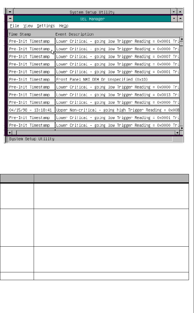
System Event Log Viewer Add-in 119
Figure 31: SEL Viewer Add-in Main Window
Table 26: SEL Viewer Menus and Options
Menu Options
File Open SEL: Views data from previously saved SEL file
Save SEL: Saves the currently loaded SEL data to a file
Clear SEL: Clears the SEL data from the BMC
Exit: Quits the SEL Viewer
View SEL Info: Displays information about the SEL (display only)
All Events: Displays the current SEL data from the BMC
By Sensor: Displays a pop-up menu allowing you to view the data from a
certain sensor type
By Event: Displays a pop-up menu allowing you to view the data from a
certain event type
Settings Display Hex/Verbose: Toggles between Hex/interpreted mode of
displaying the SEL records
Output Text/Binary: Determines whether SEL data is saved to the file
(under File - Save) in binary format or verbose format
Help About: Displays the SEL Viewer version information
3424.boo Page 119 Wednesday, September 2, 1998 9:23 AM

120 Maintaining and Troubleshooting the Gateway ALR 9200 Server
Sensor Data Record Manager
Add-In
In this window, you can:
•Examine all SDR records through the BMC (in either Hex or
Verbose mode)
•Examine SDR records by Record type (in either Hex or Verbose
mode)
•Examine SDR records from a previously stored binary file (in
either Hex or Verbose mode)
•Save the SDR records to a file (in either text or binary form)
The SDR Manager can display SDR records in either raw form
(hexadecimal) or in an interpreted, easy-to-understand textual form
(verbose).
The SDR Manager’s main window provides access to features of the add-in
through menus. Each option included on the main menu supports an
accelerator key. Accelerator keys are indicated by an underlined letter in the
text listing the option.
Figure 32 shows the SDR Manager main window. Table 27 lists the
window’s menus and options.
3424.boo Page 120 Wednesday, September 2, 1998 9:23 AM
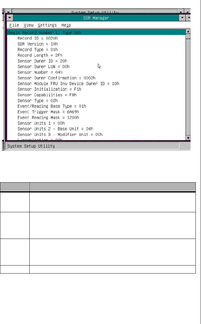
Sensor Data Record Manager Add-In 121
Figure 32: SDR Manager Main Window
Table 27: SDR Manager Menus and Options
Menu Options
File Open FRU: Opens FRU data from a previously saved file
Save SDR: Saves SDR data to a file in binary raw or verbose text format
Exit: Quits the SDR Manager
View SDR Info: Displays SDR information as returned by the GetSDRInfo interface
of the BMC
All Records: Displays all records in the SDR repository
By Record: Displays all records in the SDR repository, sorted by record type
Settings Display HEX: Displays SDR records in Hex format
Display Verbose: Displays SDR records in verbose format
Output Text: Saves SDR data in verbose format
Output Binary: Saves SDR data in binary format
Help About: Displays SDR Manager version information
3424.boo Page 121 Wednesday, September 2, 1998 9:23 AM

122 Maintaining and Troubleshooting the Gateway ALR 9200 Server
Field Replaceable Unit Manager
Add-In
In this window you can:
•Examine all FRU Inventory areas on the server (in either Hex or
Verbose mode)
•Examine individual FRU Inventory areas (in either Hex or Verbose
mode)
•Examine FRU Inventory areas from a previously stored binary file
(in either Hex or Verbose mode)
•Save the FRU Inventory areas to a file (in either text or binary
form)
The FRU Manager can display the FRU Inventory areas in either raw form
(hexadecimal) or in an interpreted, easy-to-understand textual form
(verbose). The FRU manager’s main window provides access to features of
the add-in through menus. Each option included on the main menu supports
an accelerator key. Accelerator keys are indicated by an underlined letter in
the text listing the option.
Figure 33 shows the FRU Manager main window. Table 28 lists the
window’s menus and options.
3424.boo Page 122 Wednesday, September 2, 1998 9:23 AM
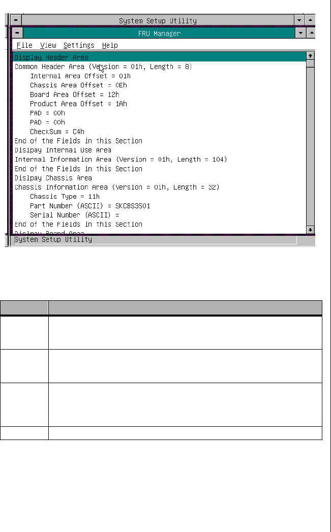
Field Replaceable Unit Manager Add-In 123
Figure 33: FRU Manager Main Window
Table 28: FRU Manager Menus and Options
Menu Options
File Open FRU: Opens FRU data from a previously saved file
Save FRU: Saves FRU data to a file in binary raw or verbose text format
Exit: Quits the FRU Manager
View FRU Info: Displays FRU information of the selected device
All FRU Areas: Displays FRU areas of all devices
By Device Type: Displays FRU areas sorted by device type
Settings Display HEX: Displays FRU areas in Hex format
Display Verbose: Displays FRU areas in verbose format
Output Text: Saves FRU data in verbose format
Output Binary: Saves FRU data in binary format
Help About: Displays FRU Manager version information
3424.boo Page 123 Wednesday, September 2, 1998 9:23 AM

124 Maintaining and Troubleshooting the Gateway ALR 9200 Server
Exiting the SSU
Exiting the SSU causes all windows to close.
1. Exit the SSU by opening the file menu in the SSU Main window.
2. Click Exit
or
Highlight Exit, and press ENTER.
To Exit the SSU
3424.boo Page 124 Wednesday, September 2, 1998 9:23 AM

Chapter 7:
Other Utilities
Contents
Introduction.......................................................... 126
Power-on Self Test .............................................. 127
Emergency Management Port Console.............. 129
How the EMP Console Works..................... 130
EMP Console Requirements........................ 132
Setting Up the Server for the EMP .............. 133
Main EMP Console Window....................... 134
Server Control Operations ........................... 136
Phonebook .................................................... 140
Management Plug-ins .................................. 141
FRU and SDR Load Utility................................. 145
When to Run the FRUSDR Load Utility..... 145
What You Need to Do.................................. 145
How You Use the FRUSDR Load Utility... 146
Cleaning Up and Exiting.............................. 150
Using the Firmware Update Utility .................... 151
Running the Firmware Update Utility......... 151
Using the Symbios SCSI Utility ......................... 152
Running the SCSI Utility ............................. 152
3424.boo Page 125 Wednesday, September 2, 1998 9:23 AM

126 Maintaining and Troubleshooting the Gateway ALR 9200 Server
Introduction
This chapter describes the Power-on Self Test (POST) and system
configuration utilities. These utilities are:
•POST: described in “Power-on Self Test” on page 127. POST
checks basic system integrity and all major components.
•BIOS Setup: described in Chapter 5, “BIOS Setup” on page 79. If
the system does not have a diskette drive, or the drive is disabled or
misconfigured, use Setup to enable it.
Or, you can move the CMOS jumper on the system board from the
default setting (Protect CMOS memory) to the Clear setting; doing
so allows most system configurations to boot. Then run the SSU to
configure the system.
•Server Setup Utility (SSU): described in Chapter 6, “The Server
Setup Utility” on page 103. Use for extended system configuration
of onboard resources and expansion cards, viewing the system
event log (SEL), setting boot device priority, or setting system
security options.
Run the SSU from a set DOS-bootable diskettes. See “What You
Need to Do” on page 106 to make a set of SSU diskettes.
Data entered in the SSU overrides data entered in Setup.
•Emergency Management Port (EMP) Console: described in
“Emergency Management Port Console” on page 129. Use the
EMP to access and monitor the server remotely.
•FRUSDR Load Utility: described in “FRU and SDR Load Utility”
on page 145. Use to update the Field Replacement Unit (FRU),
Sensor Data Record (SDR), and Desktop Management Interface
(DMI) flash components.
•BIOS Update Utility: described in “Upgrading the BIOS” on
page 98. Use to update the BIOS or recover from a corrupted
BIOS update.
•Firmware Update Utility: described in “Using the Firmware
Update Utility” on page 151. Use to update the BMC flash ROM.
•Symbios SCSI Utility: described in “Using the Symbios SCSI
Utility” on page 152. Use to configure or view the settings of the
SCSI host adapters and onboard SCSI devices in the system.
3424.boo Page 126 Wednesday, September 2, 1998 9:23 AM

Power-on Self Test 127
Power-on Self Test
Each time you turn on the system, the power-on self test (POST) runs.
POST checks the system board, processors, memory, keyboard, and most
installed peripheral devices. During the memory test, POST displays the
amount of memory it is able to access and test. The length of time needed to
test memory depends on the amount of memory installed. POST is stored
in flash memory.
1. Turn on the monitor and the system. After a few seconds, POST
begins to run.
2. After the memory test, these screen prompts and messages appear:
Keyboard Detected
Mouse Initialized
Press <F2> to enter Setup
3. If you do not press F2 and there is no device with an OS loaded, the
above message remains for a few seconds while the boot process
continues, and the system beeps once. Then this message appears:
Operating System not found
If you do not press F2 and do have a device with an OS loaded, the
boot process continues and this message appears:
Press <Ctrl><C> to enter SCSI Utility
4. Press CTRL+C if SCSI devices are installed. When the utility opens,
follow the displayed instructions to configure the onboard SCSI host
adapter settings and to run the SCSI utilities. Also see “Using the
Symbios SCSI Utility” on page 152. If you do not enter the SCSI
utility, the boot process continues.
5. Press ESC during POST to access a boot menu when POST finishes.
From this menu, you can choose the boot device or enter BIOS Setup.
To Use POST
3424.boo Page 127 Wednesday, September 2, 1998 9:23 AM

128 Maintaining and Troubleshooting the Gateway ALR 9200 Server
After POST completes, the system beeps once.
What appears on the screen after this depends on if you have an OS loaded
and if so, which one.
If the system halts before POST completes running, it emits a beep code
indicating a critical system error that requires immediate attention. If POST
can display a message on the video display screen, the speaker beeps twice
as the message appears.
Note the screen display and write down the beep code you hear; this
information is useful for your service representative. For a listing of beep
codes and error messages that POST can generate, see “Solving Problems”
on page 159.
3424.boo Page 128 Wednesday, September 2, 1998 9:23 AM

Emergency Management Port Console 129
Emergency Management Port
Console
The emergency management port (EMP) console provides an interface,
called the console manager, to the EMP. This interface allows remote server
management via a modem or direct connection. The EMP console must be
run on a separate (client) system running either Windows 95 or
Windows NT.
The following server control operations are available with the console
manager:
•Connecting to remote servers
•Powering the server on or off
•Resetting the server
•Switching the server console between EMP active and BIOS re-
direct modes
The console manager uses three management plug-ins to monitor the
server: the SEL, SDR, and FRU viewers.
The console manager also has a support plug-in phonebook, which you can
use to create and maintain a list of servers and their phone numbers. You
can launch the Connect dialog directly from the Phonebook dialog to
connect to a selected server.
3424.boo Page 129 Wednesday, September 2, 1998 9:23 AM
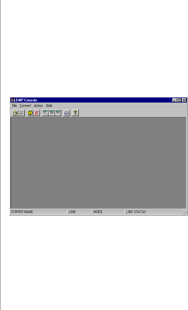
130 Maintaining and Troubleshooting the Gateway ALR 9200 Server
How the EMP Console Works
The EMP shares the COM2 port with the system. When the EMP has
control of the port, the port operates in command state. When the system
has control of it, the port operates in redirect state. When connecting to a
server, the EMP console checks to determine the current COM2 port state.
•Command state—the default COM2 state (Figure 34). In this
state, the EMP console communicates with the server firmware,
allowing the client to remotely reset or power the server up or
down. The client can also view the server SEL, FRU information,
or SDR table.
Figure 34: EMP Console in Command State
3424.boo Page 130 Wednesday, September 2, 1998 9:23 AM
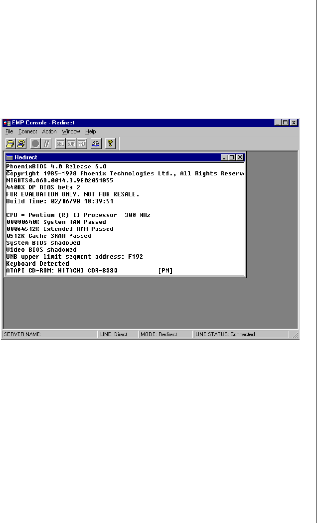
Emergency Management Port Console 131
•Redirect state—the EMP console serves as a PC ANSI terminal
window for BIOS console redirection (Figure 35). Commands
typed in this terminal window are transmitted through BIOS to the
server console, and text displayed on the server console is
displayed in the EMP console terminal window. With the EMP in
this state, you can remotely view boot messages, access BIOS
setup, and run DOS text mode applications through the EMP
console terminal window.
Figure 35: EMP Console in Redirect State
Figure 35 shows the EMP console window in redirect state with the
terminal window. The text that appears on the server monitor is also
displayed in the redirect window.
Availability of the various EMP console features is determined by two
things: the EMP access mode selected during configuration in the System
Management Submenu of the BIOS Server Menu (page 133) and whether
the server COM2 port is configured for console redirect in the BIOS.
3424.boo Page 131 Wednesday, September 2, 1998 9:23 AM
132 Maintaining and Troubleshooting the Gateway ALR 9200 Server
The three EMP access modes are disabled, pre-boot, and always active.
EMP Console Requirements
This section outlines the requirements and configurations necessary for
using the EMP console.
Operating System, Windows NT:
•Windows NT 4.0 or later
•24 MB of RAM, 32 MB recommended
•20 MB disk space
Client Configuration: The EMP console supports all COM ports on the
client system, along with any Windows NT/95 compatible modem.
Table 29: EMP Console Access Modes (Server Configured for
Console Redirect)
Mode Server is
powered off During POST After Operating
System boots
Disabled Redirect window
appears, but is blank Redirect window Redirect window
Pre-boot EMP commands
available Redirect window Redirect window
Always Active EMP commands
available Redirect window EMP commands available
* You can modify the operation mode by selections in the POST reset and POST power-up dialogs.
These are server control dialogs available with the EMP Console.
Table 30: EMP Console Access Modes (Server not Configured for
Console Redirect)
Mode Server is
powered off During POST After Operating
System boots
Disabled Redirect window
appears, but is blank Redirect window
appears, but is blank Redirect window
appears, but is blank
Pre-boot EMP commands
available EMP commands
available Redirect window
appears, but is blank
Always Active EMP commands
available EMP commands
available EMP commands
available
3424.boo Page 132 Wednesday, September 2, 1998 9:23 AM

Emergency Management Port Console 133
Server Configuration: The EMP console requires that the server COM2
port be connected to an external modem or directly connected to a serial
cable.
Direct Connect Configuration: A null modem serial cable is needed.
Connect one end of the cable into the COM2 port of the server and the
other into a port on the client machine.
Modem Configuration: On the client, the EMP console uses the Windows
application program interface (API) to determine if a modem is connected
and available. The EMP Console does not configure the modem; it should
be preconfigured through Windows.
For modem support, the server must use a Hayes-compatible 14400 bps
modem. The modem must be on the NT hardware compatibility list
provided by Microsoft. The server modem must be set in autoanswer mode
for the EMP console to be able to connect to it.
Setting Up the Server for the EMP
To use the EMP, you must configure the BIOS with specific settings. Enter
these settings in two submenus of the BIOS Server Menu: the System
Management Submenu (“System Management Submenu” on page 94) and
the Console Redirect Submenu (“Console Redirection Submenu” on
page 94). The sections below focus on the settings that must be configured
to use the EMP.
System Management Submenu
All EMP-related settings occur from the System Management Submenu of
the server Main Menu. Change only the items below; all other default
settings should remain the same.
EMP Password: Any time you attempt to initiate a connection, a prompt
for the user password appears. If you never set up the EMP password,
anyone can access the EMP by clicking OK through the password prompt.
In the EMP password area of the System Management Submenu, type in a
password of up to eight alphanumeric characters. If the system beeps, the
password was not accepted; you must enter a different password.
3424.boo Page 133 Wednesday, September 2, 1998 9:23 AM

134 Maintaining and Troubleshooting the Gateway ALR 9200 Server
EMP Access Modes: Choose either disabled, pre-boot, or always active,
depending on the type of EMP access needed. Table 29 on page 132 and
Table 30 on page 132 list what is available with a given setting.
EMP Restricted Mode Access: Set restricted mode to either enabled or
disabled. In enabled mode, the EMP console server control options, Power
On/Off and Reset, are NOT available. In disabled mode, these options are
available.
EMP Direct Connect/Modem Mode: Select Direct Connect if a null
modem serial cable directly connects the server COM2 port to the EMP
console client machine. If they are connected via a modem, select Modem
Mode.
Console Redirection Submenu
To use the EMP, you must set the following options exactly as noted.
COM Port Address: Select 2F8. This is the COM2 port that the EMP must
use. The IRQ# setting is automatically assigned with the correct number
based on the COM port address choice.
Baud Rate: Select 19.2k.
Console Type: Choose PC ANSI.
Flow Control: Choose CTS/RTS + CD.
Main EMP Console Window
The main EMP console window provides a graphical user interface (GUI)
to access server control operations and to launch the management plug-ins.
A menu and tool bar at the top of the GUI provide options to initiate plug-
ins and other support features. A status bar at the bottom displays
connection information like server name, line status, and mode.
3424.boo Page 134 Wednesday, September 2, 1998 9:23 AM
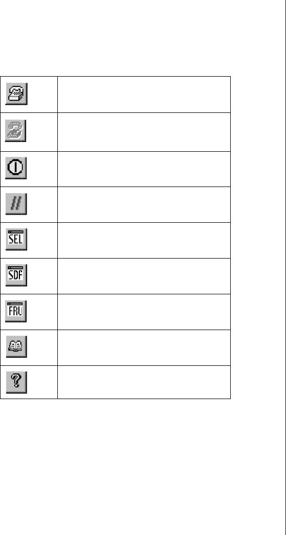
Emergency Management Port Console 135
Toolbar
The tool bar buttons (Table 31) combine server control and management
plug-in options available from the Connect and Action menus.
Status Bar
The status bar is displayed at the bottom of the current window. It contains
the following status information:
•Server Name: The name of the connected server.
•Line: The type of line connection (direct or modem).
Table 31: Toolbar Buttons
Connects to a selected server
Disconnects from the currently connected
server
Powers the selected server on or off
Resets the selected server
Opens the SEL viewer
Opens the SDR viewer
Opens the FRU viewer
Opens the Phonebook
Opens online help
3424.boo Page 135 Wednesday, September 2, 1998 9:23 AM

136 Maintaining and Troubleshooting the Gateway ALR 9200 Server
•Mode: Either redirect or EMP, depending on whether the EMP has
control of the COM2 port.
•Line Status: Gives status information on the server connection.
For example, if a server is connected, the status bar says
“Connected.” Otherwise, the line is blank.
EMP Console Main Menu
•File
•Exit: Exits the EMP console
•Connect
•Disconnect: Disconnects the server connection.
•[Re]Connect: Raises the connect dialog.
•(A list of the five most recent connections): Initiates
connection to selected server.
•Action
•Power On/Off: Powers the server on or off with POST power-
up options.
•Reset: Resets the server with POST reset options.
•SEL Viewer: Opens the SEL viewer.
•SDR Viewer: Opens the SDR viewer.
•FRU Viewer: Opens the FRU viewer.
•Phonebook: Opens the phonebook dialog.
•Help: Provides version information and help topics for the EMP
console.
Server Control Operations
Three server control operations are available from the menu or toolbar of
the main EMP console window, remote server connection, powering the
server on and off, and resetting the server. The server console mode can
also be switched between EMP active and BIOS redirect modes through
POST power-up and reset options.
3424.boo Page 136 Wednesday, September 2, 1998 9:23 AM
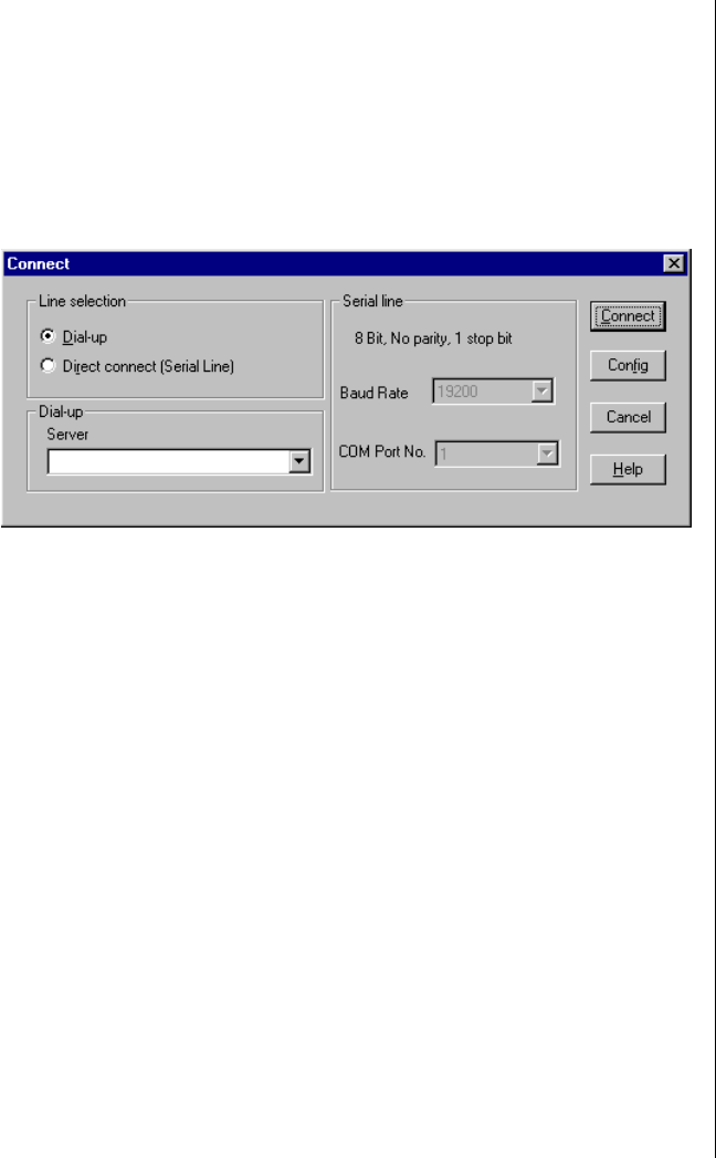
Emergency Management Port Console 137
Connect to Remote Server
Select [Re]Connect from the Connect menu and follow the Connect dialog
shown in Figure 36 allows you to connect to a selected server. If the client
machine is already connected to a server, initiating connection generates a
warning message. The message states that the existing connection will be
terminated if you continue trying to initiate the new connection. You are
prompted to enter the EMP password whenever a connection is attempted.
Figure 36: Connect Dialog
Options available in the dialog are:
•Line Selection: Allows distinction between direct or dial-up
modem connection to the server.
•Dial-up: Connects to a selected server with a modem.
•Direct connect (Serial Line): Connects to the selected server
directly using a null modem serial cable.
•Server: Displays a list of available servers in a dropdown edit list
box. You can select or enter a server name; a server must be
selected wen the line selection is dial-up.
•Serial Line: Must be filled out when the line selection is set to
direct connect (serial line).
•Baud Rate: Specifies baud rate; must be 19200 for EMP to
connect properly.
•COM Port No.: Sets the COM port number to which the null
modem serial cable is connected.
3424.boo Page 137 Wednesday, September 2, 1998 9:23 AM
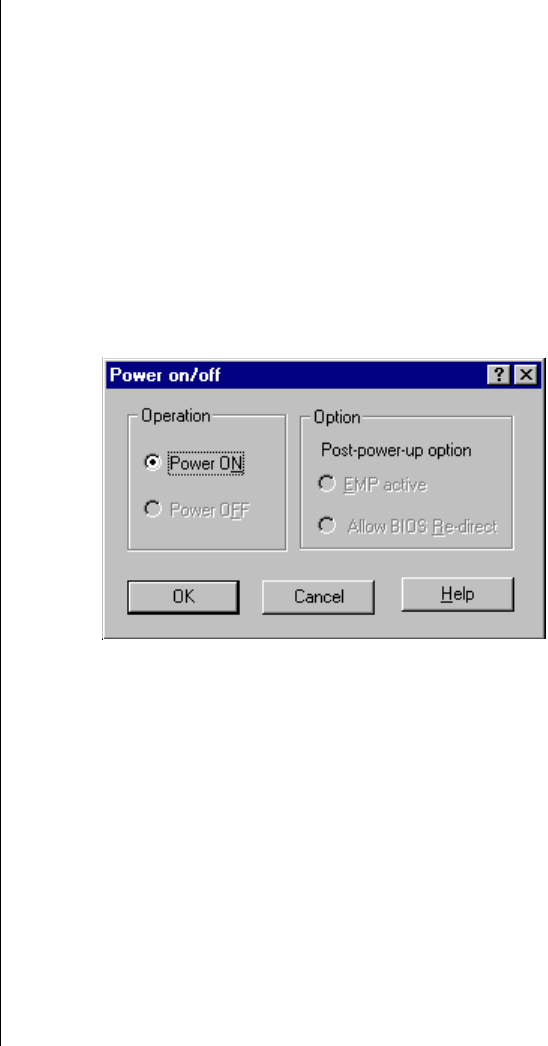
138 Maintaining and Troubleshooting the Gateway ALR 9200 Server
•Connect: Initiates connection to the server. When you click this
button, you are prompted for the EMP password.
•Config: Displays the Phonebook dialog.
•Cancel: Exit the Connect dialog with no action taken.
•Help: Display dialog-level help information.
Power On/Off the Server Remotely
Selecting Power On/Off from the Action Menu allows you to power the
server on or off, with POST power-up options. It generates the Power on/off
dialog (Figure 37).
Figure 37: Power On/Off Dialog
Options available in the dialog are:
•Power ON: Powers on the server.
•Power OFF: Powers off the server. This option is not allowed if the
server is configured in restricted mode for EMP operations.
•Post-power-up option: Sets the server mode EMP active or BIOS
redirection. The setting is effective at the next power-up. The
default selection is EMP active.
•Cancel: Exits the dialog with no action taken.
•Help: Displays dialog-level help information.
3424.boo Page 138 Wednesday, September 2, 1998 9:23 AM
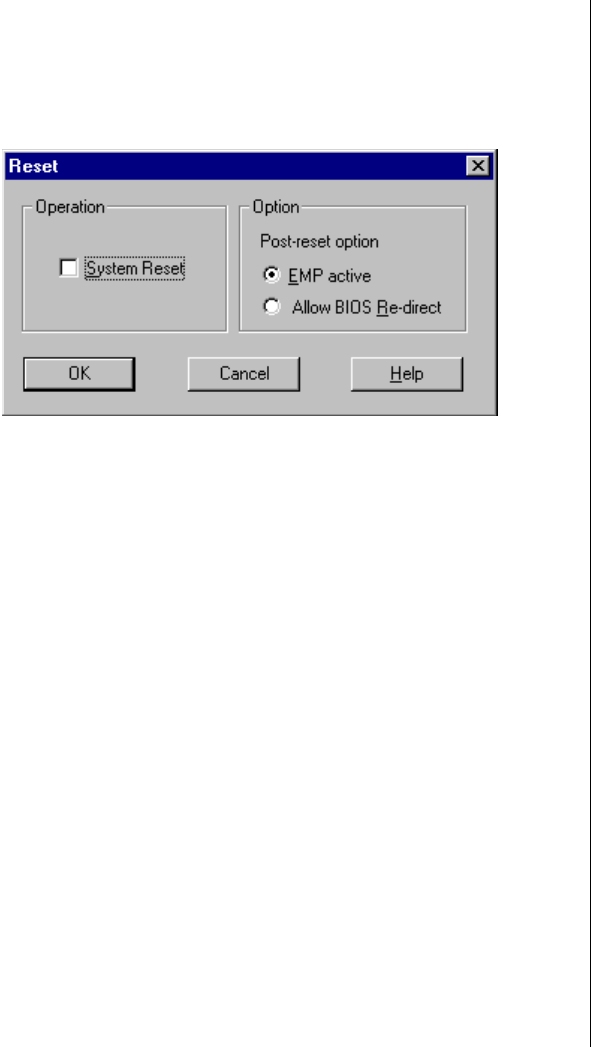
Emergency Management Port Console 139
Reset the Server Remotely
Selecting Reset from the Action Menu generates the Reset dialog
(Figure 38) so that you can remotely reset the server with POST reset
options.
Figure 38: Reset Dialog
Options available in the dialog are:
•System Reset: Resets the server with the selected POST reset
options. This operation is not allowed if the server is configured in
restricted mode for EMP operations.
•Option Group: Sets the POST reset option that will be effective
after reset. The options are EMP active or BIOS redirection. The
default selection is EMP active.
•Cancel: Exits the dialog with no action taken.
•Help: Displays dialog-level help information.
3424.boo Page 139 Wednesday, September 2, 1998 9:23 AM
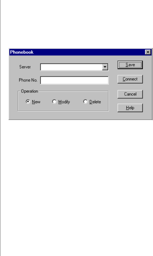
140 Maintaining and Troubleshooting the Gateway ALR 9200 Server
Phonebook
The EMP console provides a phonebook (Figure 39), a support plug-in that
stores names and numbers of servers in a list that can be updated by adding,
modifying, or deleting entries. You can open the phonebook from the Main
Menu and tool bars, or launch it by clicking the Config button.
Figure 39: Phonebook Dialog
Options available in the dialog are:
•Server: Displays a dropdown list of server names previously
stored in the phonebook. If the New radio button is selected in the
Operation area, the server area is cleared.
•Phone No.: Displays the number of the selected server. If the New
radio button is selected in the Operation area, this area is cleared.
•Operation
•New: Makes a new entry in the phonebook. Selecting this
option clears the Server and Phone No. fields. You must click
Save to add the entry to the phonebook.
•Modify: Edits an existing entry. Before selecting this option,
you must first select an existing entry from the Server
dropdown edit box and modify the existing phone number.
Click Save to store this entry in the phonebook.
3424.boo Page 140 Wednesday, September 2, 1998 9:23 AM

Emergency Management Port Console 141
•Delete: Deletes an entry from the phonebook. You must first
select an existing server from the Server dropdown edit box
before selecting this option. Click Save to delete the entry.
•Save: Saves a new or modified phonebook entry or deletes an
entry if you have already selected the Delete radio button.
•Connect: Raises the Connect dialog with the server from the
phonebook Server dropdown edit box already populating the
Connect dialog Server dropdown edit box.
•Cancel: Exits the dialog with no action taken.
•Help: Displays dialog-level help information.
Management Plug-ins
System Event Log Viewer
The system event log (SEL) viewer can display records in either
hexadecimal or text (verbose) form. These options are available through the
SEL viewer:
•View the SEL from a file
•Save the SEL to a file
•View SEL summary information
•View all SEL entries
•View SEL info by event type
•View SEL info by sensor type
•Set SEL display mode to either Hex or verbose mode
•Set the SEL output file format to either text or binary format
•Close the SEL viewer
•Exit the EMP console
3424.boo Page 141 Wednesday, September 2, 1998 9:23 AM

142 Maintaining and Troubleshooting the Gateway ALR 9200 Server
SEL Viewer Menu Options
The following menu options are available on the SEL viewer menu bar:
•File
•Open: Allows you to view SEL data from a previously saved
file if it was stored in binary format. Selecting the Open Menu
item lets you specify a filename under which the data are
found. The default filename is “SELLOG.DAT.” If the file
cannot be opened, the program displays an error message.
•Close: Closes the SEL viewer.
•Save As: Dumps the SEL data to a file in either binary or text
format. The binary file can be retrieved later. This option lets
you specify a filename to which the data is saved. The default
filename is “SELLOG.DAT.” If no data exist, the system
displays an error message.
•Exit: Exits the EMP console.
•Connect
•View
•SEL Information: Displays SEL summary information.
•All Events: Displays all events in the SEL.
•By Sensor Type: Displays all events in the SEL generated by
a specific sensor type, e.g., voltage, temperature, etc.
•By Event: Displays all events in the SEL of a particular type,
for example, by memory or threshold. A pop-up menu lets you
select the event type to display. This menu displays all event
types that can be generated by the hardware.
•Settings: Lets you change several operating parameters for the
SEL viewer. This menu displays the following suboptions:
•Display HEX/Verbose: Toggles between HEX mode and
interpreted mode of displaying SEL records.
•Output Text/Binary: Specifies whether SEL data is saved to
the file in binary format or verbose format.
•Window: Gives options for displaying currently open windows.
•Help: Provides version information for the SEL viewer and
provides help topics on the EMP console.
3424.boo Page 142 Wednesday, September 2, 1998 9:23 AM

Emergency Management Port Console 143
Sensor Data Record Viewer
The sensor data record (SDR) viewer lets you view the records retrieved
from the SDR repository. Options available through the SDR viewer are:
•View all SDR records
•View SDR entries by SDR type
•View SDR summary information
•Set SDR display mode to either Hex or verbose mode
•Close the SDR viewer
•Exit the EMP console
SDR Viewer Menu Options
The SDR viewer menu bar contains the following:
•File
•Close: Closes the SDR viewer.
•Exit: Exits the EMP console.
•View
•Display all Records: Displays all records from the SDRR.
•SDR Type: Displays the records of a particular SDR type.
Select an SDR type from a pop-up menu that displays all of
the SDR types available for the hardware.
•SDR Info: Displays the SDR summary information.
•Settings: Lets you change operating parameters for the SDR
viewer. This menu displays the following suboption:
•Display HEX/Verbose: Toggles between HEX mode and
interpreted mode of display.
•Window: Gives options for displaying currently open windows.
•Help: Provides version information for the SDR viewer and
provides help topics on the EMP console.
3424.boo Page 143 Wednesday, September 2, 1998 9:23 AM

144 Maintaining and Troubleshooting the Gateway ALR 9200 Server
FRU Viewer
The FRU viewer lets you view data from the server system board FRU
information area. Options available with the FRU viewer are:
•View all FRU records
•View FRU summary information
•Set FRU display mode to either Hex or verbose mode
•Close the FRU viewer
•Exit the EMP console
FRU Viewer Menu Options
The following menu options are on the FRU viewer menu bar:
•File
•Close: Closes the FRU viewer.
•Exit: Exits the EMP console.
•View
•Display all Records: Displays all FRU data, which consist of
chassis, board, and product information.
•FRU Info: Displays the FRU summary information.
•Settings: Lets you change operating parameters for the FRU
viewer. This menu displays the following suboption:
•Display HEX/Verbose: Toggles between HEX mode and
interpreted mode of displaying FRU records.
•Window: Gives options for displaying currently open windows.
•Help: Provides version information for the FRU viewer and
provides help topics on the EMP console.
3424.boo Page 144 Wednesday, September 2, 1998 9:23 AM

FRU and SDR Load Utility 145
FRU and SDR Load Utility
The Field Replacement Unit (FRU) and Sensor Data Record (SDR) load
utility is a DOS-based program used to update the server management
subsystem product level FRU, SDR, and the Desktop Management
Interface (DMI) nonvolatile storage components. The utility:
•Discovers the product configuration based on instructions in a
master configuration file
•Displays the FRU information
•Updates the EEPROM associated with the system board
management controller (BMC) that holds the SDR and FRU area
•Updates the DMI FRU area located in the BIOS nonvolatile
storage device
•Generically handles FRU devices that might not be associated with
the BMC
When to Run the FRUSDR Load Utility
You should run the FRUSDR load utility each time you upgrade or replace
the hardware in your server, excluding expansion cards, hard drives, and
RAM. For example, if you replace an array of fans, you need to run the
utility. It programs the sensors that need to be monitored for server
management.
Because the utility must be reloaded to properly initialize the sensors after
programming, turn the server off and remove the AC power cords from the
server. Wait approximately 30 seconds, then reconnect the power cords and
turn on the server.
What You Need to Do
You must run the utility from diskettes provided with the server and you
must follow the instructions in the included README.TXT file.
If the diskette drive is disabled, or improperly configured, you must use
BIOS Setup to enable it. If necessary, you can disable the drive after you are
done with the FRUSDR utility.
3424.boo Page 145 Wednesday, September 2, 1998 9:23 AM

146 Maintaining and Troubleshooting the Gateway ALR 9200 Server
How You Use the FRUSDR Load Utility
The utility:
•Is compatible with ROM-DOS Ver. 6.22, MS-DOS Ver. 6.22, and
later versions
•Accepts CFG, SDR, and FRU load files (the executable file for the
utility is frusdr.exe)
•Requires the following supporting files
• one or more .fru files describing the system field replaceable
units
• a .cfg file describing the system configuration
• an .sdr file describing the sensors in the system
Command Line Format
The command line uses several keys. Table 32 lists the keys and their
definitions. The basic command line format is
frusdr [-?] [-h] [-d {dmi, fru, sdr}] [-cfg filename.cfg] [-fru filename.fru]
Parsing the Command Line
The FRUSDR load utility allows only one command line function at a time.
A command line function can consist of two parameters. Example: -cfg
filename.cfg. Invalid parameters cause an error message and exit the
Table 32: Command Line Format Elements
Command Description
frusdr Is the name of the utility
-? or -h Displays usage information
-d {dmi, fru, sdr} Displays requested area only
-cfg filename.cfg Uses custom CFG file
-p Pause between blocks of data
-v Verbose, display any additional details
3424.boo Page 146 Wednesday, September 2, 1998 9:23 AM

FRU and SDR Load Utility 147
program. You can use either a slash (/) or a minus sign (-) to specify
command line options. The -p and -v flags can be used in conjunction with
any of the other options.
Displaying Usage Information
When the utility is run with the -? or -h command line flags, the following
message is displayed when the verbose flag -v is added to the help
command:
FRU & SDR Load Utility Version 2.1 Revision R.1.1
Copyright (c) 1998, Intel Corporation, All Rights Reserved
This utility must be run from a system executing DOS. Running in a
Windows DOS box is insufficient and provides incorrect results.
Programming the BMC FRU area clears the SDR table; therefore the SDR
table must be reprogrammed. Upon completing the programming of the
FRU and SDR areas, the server should be rebooted.
The system displays the following information if the -v option is included
in the command line.
The /D FRU command may be followed with up to 16 device addresses.
These device addresses are used to view up to 16 different FRU areas,
instead of the default of displaying the BMC FRU. The arguments
following the "-d FRU" are in the same order and value as the NVS_TYPE,
NVS_LUN, DEV_BUS and DEV_ADDRESS which are found in the FRU
file header in each FRU file. The LUN address is optional. If the LUN
address is used, it must start with an ’L’.
Usage: FRUSDR -d fru (device) [lun] (bus) (addr) (addr2) (etc)
Example: FRUSDR /D FRU IMBDEVICE L00 00 C0 C2
The configuration file may be used to load multiple FRU and SDR files. In
the configuration file, you may define which FRU and SDR areas are to be
programmed. Additionally, you may request information from the user or
ask the user to choose which areas to program.
3424.boo Page 147 Wednesday, September 2, 1998 9:23 AM

148 Maintaining and Troubleshooting the Gateway ALR 9200 Server
Displaying a Given Area
When the utility is run with the -d DMI, -d FRU, or -d SDR command line
flag, the indicated area is displayed. Each area represents one sensor for
each instrumented device in the server. If the given display function fails
because of an inability to parse the data present or a hardware failure, the
utility displays an error message and exits.
Displaying the DMI Area
Each DMI area displayed is headed with the DMI area designated name. In
each area, each field has a field name header followed by the field in ASCII
or as a number.
Example:
To display the DMI area, type frusdr -d dmi and press ENTER.
Displaying the FRU Area
The FRU area is displayed in ASCII format when the field is ASCII or as a
number when the field is a number. Each FRU area displayed is headed
with the FRU area designated name. Each field has a field name header
followed by the field in ASCII or as a number. The board, chassis, and
product FRU areas end with an END OF FIELDS CODE that indicates
there are no more data in the area. The internal use area is displayed in hex
format, 16 bytes per line.
Example:
To display the FRU area, type frusdr -d fru and press ENTER.
Displaying the SDR Area
The SDR nonvolatile storage area is displayed in hex format. The data are
separated by a sensor record number X header, where X is the number of
that sensor record in the SDR area. The next line after the header is the
sensor record data in hex format delineated by spaces. Each line holds up to
3424.boo Page 148 Wednesday, September 2, 1998 9:23 AM

FRU and SDR Load Utility 149
16 bytes. The data on each line are followed by the same data in ASCII
format; nonprintable characters (ch < 32 || ch > 126) are substituted by a
period (.).
Example:
To display the SDR area, type frusdr -d sdr and press ENTER.
Using a Specified CFG File
The utility can be run with the command line parameter of -cfg
filename.cfg. The filename can be any DOS-accepted, eight-character
filename string. The utility loads the specified CFG file and uses the entries
in that file to probe the hardware and to select the proper SDRs to load into
nonvolatile storage.
Displaying the Utility Title and Version
The utility displays its title:
FRU & SDR Load Utility, Version 2.0, Revision X.XX
where X.XX is the revision number for the utility.
Configuration File
The configuration file is in ASCII text. The utility executes commands
formed by the strings present in the configuration file. These commands
cause the utility to run tasks needed to load the proper SDRs into the
nonvolatile storage of the BMC and possibly generic FRU devices. Some of
the commands may be interactive and require you to make a choice.
Prompting for Product Level FRU Information
Through the use of a configuration file, the utility might prompt you for
FRU information.
3424.boo Page 149 Wednesday, September 2, 1998 9:23 AM

150 Maintaining and Troubleshooting the Gateway ALR 9200 Server
Filtering Records From the SDR File
The MASTER.SDR file has all the possible SDRs for the system. These
records might need to be filtered based on the current product
configuration. The configuration file directs the filtering of the SDRs.
Updating the SDR Nonvolatile Storage Area
After the utility validates the header area of the supplied SDR file, it
updates the SDR repository area. Before programming, the utility clears the
SDR repository area. The utility filters all tagged SDRs depending on the
product configuration set in the configuration file. Nontagged SDRs are
automatically programmed. The utility also copies all written SDRs to the
SDR.TMP file; it contains an image of what was loaded. The TMP file is
also useful for debugging the server.
Updating the FRU Nonvolatile Storage Area
After the configuration is determined, the utility updates the FRU
nonvolatile storage area. First it verifies the common header area and
checksum from the specified FRU file. The internal use area is read out of
the specified.FRU file and is programmed into the nonvolatile storage. The
chassis area is read out of the specified.FRU file. Finally, it reads the
product area out of the specified FRU file, then the area is programmed into
the FRU nonvolatile storage. All areas are also written to the FRU.TMP
file.
Updating the DMI FRU Nonvolatile Storage Area
After programming the BMC FRU area, the utility programs chassis, board,
and product FRU information to the DMI fields, if the DMI flag follows
each FRUAREA command in the configuration file.
Cleaning Up and Exiting
If an update was successfully performed, the utility displays a single
message and then exits.
If the utility fails, it immediately exits with an error message and exit code.
3424.boo Page 150 Wednesday, September 2, 1998 9:23 AM

Using the Firmware Update Utility 151
Using the Firmware Update Utility
The Firmware Update Utility (FUU) is a DOS-based program used to
update the BMC firmware code.
Running the Firmware Update Utility
You need to run the firmware update utility (FUU) only if new firmware
code is necessary.
1. Create a DOS-bootable diskette. The version of DOS must be 6.0 or
higher.
2. Place the firmware update utility (FWUPDATE.EXE) and the *.hex
file on the diskette. Make a note of the *.hex file name, because you
will need it later.
3. Insert the diskette into drive A and boot to it.
4. At the DOS prompt, run the executable file (FWUPDATE.EXE).
5. The utility displays a menu screen. Select Upload Flash.
6. The utility asks for a file name. Enter the name of the *.HEX file.
7. The program loads the file and then asks if it should upload the boot
block. Press N to continue.
8. The program next asks if it should upload the operational code. Press
Y to continue.
9. Once the operational code has been updated and verified, press any
key to continue. Then press ESC to exit the program.
10. Shut the system down and remove any diskettes in the system.
11. Disconnect all AC power cords from the system and wait 60 seconds.
12. Reconnect the AC power cords and power up the system.
To Run the FUU
3424.boo Page 151 Wednesday, September 2, 1998 9:23 AM

152 Maintaining and Troubleshooting the Gateway ALR 9200 Server
Using the Symbios SCSI Utility
The Symbios SCSI utility detects the SCSI host adapters on the system
board. Use the utility to:
•Change default values
•Check and/or change SCSI device settings that may conflict with
those of other devices in the server
Running the SCSI Utility
When this message appears on the monitor:
Press Ctrl-C to run SCSI Utility...
Press CTRL+C to run the utility. When it appears, choose the host adapter
that you want to configure.
3424.boo Page 152 Wednesday, September 2, 1998 9:23 AM

Chapter 8:
Trouble-
shooting
Contents
Introduction.......................................................... 154
Computer Virus Notice ....................................... 155
Viruses .......................................................... 155
Types of Viruses........................................... 155
Virus Contamination.................................... 155
Protecting Your System ............................... 156
Virus Prevention........................................... 156
Troubleshooting Checklist.................................. 158
Verifying the Configuration......................... 158
Troubleshooting Guidelines......................... 158
Solving Problems................................................. 159
Resetting the System.................................... 159
Initial System Startup................................... 159
Running New Application Software ........... 160
The System Has Been Running Correctly... 161
More Problem-solving Procedures.............. 162
Specific Problems and Corrective Actions.. 164
Error and Informational Messages...................... 170
POST Codes and Countdown Codes........... 170
POST Error Codes and Messages................ 173
3424.boo Page 153 Wednesday, September 2, 1998 9:23 AM

154 Maintaining and Troubleshooting the Gateway ALR 9200 Server
Introduction
If your system does not operate correctly, re-read the instructions for the
procedure(s) you have performed. If an error occurs within an application,
consult the documentation supplied with the software.
This section identifies solutions to common problems. If the suggestions in
this chapter do not resolve your problem, try calling Technical Support.
Note:
Under no circumstances
return any equipment
without obtaining a Return
Material Authorization (RMA)
number.
3424.boo Page 154 Wednesday, September 2, 1998 9:23 AM

Computer Virus Notice 155
Computer Virus Notice
Viruses
A virus is a program written with malicious intent for the sole purpose of
creating havoc in a computer system. It attaches itself to executable files or
boot sectors, so it can replicate and spread.
Some viruses may only cause your system to beep or display messages or
images on the screen. Other viruses are highly destructive and corrupt or
erase the contents of your files or disks. To be safe, never assume any virus
is harmless.
Types of Viruses
Viruses are identified by how they infect computer systems.
•Program viruses infect executable program files such as .com,
.exe, .ovl, .drv, .sys, and .bin.
•Macro viruses infect macro files of programs such as word
processing and spreadsheet programs.
•Boot viruses attach themselves to a boot record, master boot, FAT,
or partition table.
•Multipartite viruses are both program and boot infectors.
Virus Contamination
There are many ways a virus can spread and infect your system. However, a
virus is inactive until the infected program is executed, or a boot record is
read. Thereafter, the virus loads itself into system memory and begins to
copy and spread itself.
Disks used in a contaminated system can get infected and, in turn, transfer
the virus when used in another system. A virus can also spread via
programs downloaded from bulletin boards or the Internet. Remember that
viruses cannot appear all by themselves. They have to be written, then
spread through direct contact with executable programs or boot sectors.
3424.boo Page 155 Wednesday, September 2, 1998 9:23 AM

156 Maintaining and Troubleshooting the Gateway ALR 9200 Server
Protecting Your System
Awareness is the key. You need to learn about the existence of viruses, how
they spread, and what to do to protect your system by reducing the
likelihood of virus contamination. The following may help:
•Obtain an anti-virus program and make it a habit to scan the
system regularly. These programs may be purchased from a local
software store or obtained via shareware on the Internet or online
service providers such as CompuServe, Prodigy, AOL, or
DeltaNet.
•Make backup copies of all files and write-protect the disks.
•Obtain all software from reputable sources and always scan new
software for any viruses before installing files.
If you suspect your system has been infected, you must find and remove the
viruses immediately using an anti-virus program. Next, reboot your system
as follows: shut the system down, then turn it off for at least 15 seconds
before turning it back on. This is the only way to ensure the virus does not
remain in your system RAM.
Virus Prevention
We stand by the integrity of our products. Our staff takes every precaution
to ensure our files are free from viruses. These precautions include the
following:
•We use McAfee VirusScan, a leading anti-virus software that
detects and removes over 95% of known viruses and provides
comprehensive protection including local and network drives, CD-
ROMs, floppies, boot sectors, and partition tables. VirusScan also
provides advanced protection against unknown viruses. We
continuously update and use the most current version of McAfee
VirusScan on all of our products.
•All master disks are write-protected and scanned at least twice
before release.
•Sample production disks are periodically scanned as an additional
quality check.
3424.boo Page 156 Wednesday, September 2, 1998 9:23 AM

Computer Virus Notice 157
•All incoming products such as systems to repair, vendor disks,
hard drives, and trade-show units are scanned for viruses.
•All systems are given a final test before shipping.
Unfortunately, today’s technology makes the creation of newer viruses
possible, some of which can elude even the best scanners available. Hence,
there is no absolute guarantee of virus immunity on any product. If you
think you have received an infected product from us, please contact
Technical Support. Our staff will assist you in correcting the problem.
3424.boo Page 157 Wednesday, September 2, 1998 9:23 AM

158 Maintaining and Troubleshooting the Gateway ALR 9200 Server
Troubleshooting Checklist
Before turning on the system, make sure that:
•The power cord is connected to the AC power-in connector and an
AC outlet.
•The AC outlet is supplying power.
•If a power strip is used, it is turned on, and the circuit breaker is set.
•The voltage selection switch on the system power supply reflects
the proper voltage.
Verifying the Configuration
If your system is not operating correctly, the BIOS may contain an invalid
configuration parameter. Enter the BIOS program and check your
configuration settings, see “BIOS Setup” on page 79 for complete
instructions.
Troubleshooting Guidelines
As you troubleshoot your system, keep the following guidelines in mind:
•Never remove the system cover while the system is turned on.
•Do not attempt to open the monitor; it is extremely dangerous.
Even if the monitor’s power is disconnected, stored energy within
the monitor’s components can offer a painful or harmful
experience.
•If a peripheral such as the keyboard, mouse, drive, or printer does
not appear to work, verify that all connections are secure.
•If an error message displays on the screen, write it down, word for
word. You may be asked about it when calling Technical Support.
•Only qualified personnel should open the system for maintenance.
•If you feel you are qualified to maintain the system yourself, make
certain you are properly grounded before opening the system
chassis. See Chapter 1, “System Access”, for more information on
preventing electrostatic damage to the system.
3424.boo Page 158 Wednesday, September 2, 1998 9:23 AM
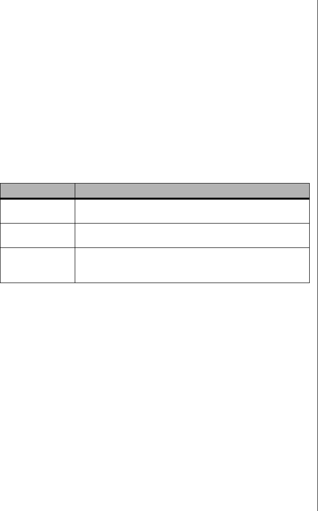
Solving Problems 159
Solving Problems
This chapter helps you identify and solve problems that might occur while
you are using the system.
Resetting the System
Some problems can be solved simply by resetting the system. A system
reset clears memory, and resets many registers to initial startup values. If
the data in memory or any registers has become corrupt or has been
improperly set during operation, a system reset will correct the problem.
Table 33 lists the various ways in which the system can be reset.
Initial System Startup
Problems that occur at initial system startup are usually caused by incorrect
installation or configuration. Hardware failure is a less frequent cause.
Checklist
•Are all cables correctly connected and secured?
•Are all cables correctly connected and secured?
•Are the processors fully seated in their slots on the system board?
•Are all ISA and PCI cards fully seated in their slots on the system
board?
•Are all switch and jumper settings on the system board correct?
Table 33: System Reset Methods
Key or Button Type of Reset
CTRL+ALT+DEL Soft boot reset, which clears system memory and reloads
the operating system.
Reset button Clear system memory, restart POST, and reload the
operating system.
Power off/on Cold boot reset, which clears system memory, restarts
POST, reloads the operating system, and halts power to all
peripherals.
3424.boo Page 159 Wednesday, September 2, 1998 9:23 AM

160 Maintaining and Troubleshooting the Gateway ALR 9200 Server
•Are all jumper and switch settings on expansion cards and
peripheral devices correct? To check these settings, refer to the
manufacturer’s documentation that comes with them. If applicable,
ensure that there are no conflicts—for example, two expansion
cards sharing the same interrupt.
•Are all DIMMs installed correctly?
•Are all peripheral devices installed correctly?
•If the system has a hard disk drive, is it properly formatted or
configured?
•Are all device drivers properly installed?
•Are the configuration settings made with the SSU correct?
•Is the operating system properly loaded? Refer to the operating
system documentation.
•Did you press the system power on/off switch on the front panel to
turn the server on (power-on light should be lit)?
•Are the system power cords properly connected to the system and
plugged into a NEMA 5-15R outlet for 100-120 V∼ or a NEMA 6-
15R outlet for 200-240 V∼?
•Is AC power available at the wall outlet?
•If these items are correct but the problem recurs, see “Solving
Problems” on page 159.
Running New Application Software
Problems that occur when you run new application software are usually
related to the software. Faulty equipment is much less likely, especially if
other software runs correctly.
Checklist
•Does the system meet the minimum hardware requirements for the
software? See the software documentation.
•Is the software an authorized copy? If not, get one; unauthorized
copies often do not work.
•If you are running the software from a diskette, is it a good copy?
3424.boo Page 160 Wednesday, September 2, 1998 9:23 AM

Solving Problems 161
•If you are running the software from a CD-ROM disk, is the disk
scratched or dirty?
•If you are running the software from a hard disk drive, is the
software correctly installed? Were all necessary procedures
followed and files installed?
•Are the correct device drivers installed?
•Is the software correctly configured for the system?
•Are you using the software correctly?
•If the problems persist, contact the software vendor’s customer
service representative.
The System Has Been Running Correctly
Problems that occur after the system hardware and software have been
running correctly often indicate equipment failure. Many situations that are
easy to correct, however, can also cause such problems; sometimes the
problem stems from changes made to the system, such as hardware or
software that has been added or removed.
Checklist
•If you run the software from diskette, use a new copy of the
software.
•If you run the software from a CD-ROM, try a different disc to see
if the problem occurs on all disks.
•If you run the software from a hard drive, run it from a diskette. If
the software runs correctly, there is a problem with the copy on the
hard drive. Reinstall the software on the hard drive, and run it
again. Make sure all necessary files are installed.
•If the problems are intermittent, there may be a loose cable, dirt in
the keyboard (if keyboard input is incorrect), a marginal power
supply, or other random component failures.
•If you suspect that a transient voltage spike, power outage, or
brownout may have occurred, reload the software and run it again.
(Symptoms of voltage spikes include a flickering video display,
unexpected system reboots, and failure to respond to commands.)
Note:
If you are getting random
errors in your data files, they
may be getting corrupted by
voltage spikes on your
power line. If you are
experiencing any of the
symptoms that might
indicate voltage spikes on
the power line, you may
want to install a surge
suppressor between the
power outlet and the system
power cords.
3424.boo Page 161 Wednesday, September 2, 1998 9:23 AM

162 Maintaining and Troubleshooting the Gateway ALR 9200 Server
More Problem-solving Procedures
This section provides a more detailed approach to identifying a problem
and locating its source.
Preparing the System for Diagnostic Testing
If the checks described in the preceding pages do not correct the problem,
you may need to run some diagnostics programs. Most diagnostics
programs require rebooting or the closure of all running software.
1. Turn off the system and all external peripheral devices. Disconnect all
of them from the system, except the keyboard and video monitor.
2. Make sure the system power cords are plugged into a properly
grounded AC outlet.
3. Make sure your video display monitor and keyboard are correctly
connected to the system. Turn on the video monitor. Set its brightness
and contrast controls to at least two-thirds of their maximum ranges
(see the documentation supplied with your video display monitor).
4. If the operating system normally loads from the hard disk drive, make
sure there is no diskette in drive A. Otherwise, place a diskette
containing the operating system files in drive A.
5. Turn on the system. If the power LED does not light, see “Power Light
Does Not Light” on page 164.
To Run Diagnostics
Caution!
Before disconnecting any
peripheral cables from the
system, turn off the system
and any external peripheral
devices. Failure to do so can
cause permanent damage
to the system and/or the
peripheral devices.
3424.boo Page 162 Wednesday, September 2, 1998 9:23 AM

Solving Problems 163
Using PCDiagnostics
A diagnostics package for the system is provided with the system. For
documentation about the test modules, see the Diagnostic help files that end
with the extension .HLP. They are ASCII files that you can print to form a
manual of all tests in this product.
•The program called Testview uses a simple DOS-based menu
system.
•The program called T.EXE is not for Windows or DOS; you can
access it at the command line prompt without having a hard drive
installed.
•The README.TXT file for diagnostics tells how to install the
program.
Monitoring POST
See “Power-on Self Test” on page 127, for more information about the
POST utility and its functions.
Verifying Proper Operation of Key System Lights
As POST determines the system configuration, it tests for the presence of
each mass storage device installed in the system. As each device is checked,
its activity light should turn on briefly. Check for the following:
•Does the diskette drive activity light turn on briefly? If not, see
“Diskette Drive Activity Light Does Not Light” on page 167.
•If a second diskette drive is installed, does its activity light turn on
briefly? If not, see “Diskette Drive Activity Light Does Not Light”
on page 167.
•If there is a hard disk drive or SCSI devices installed in the system,
does the hard disk drive activity light on the control panel turn on
briefly? If not, see “Hard Disk Drive Activity Light Does Not
Light” on page 168.
Caution!
The diagnostic package
contains many optional tests
that should be used only by
a user with advanced
technical knowledge.
Inadvertent actions could be
damaging, such as running
a hard drive write test on a
hard disk. All tests that
require external hardware,
user interaction, or are
destructive, are disabled in
the default configurations.
Before using such a test,
make sure you read and
understand the help
information for that test.
3424.boo Page 163 Wednesday, September 2, 1998 9:23 AM

164 Maintaining and Troubleshooting the Gateway ALR 9200 Server
Confirming the Loading of the Operating System
Once the system boots, the operating system prompt appears on the screen.
The prompt varies according to the operating system. If the operating
system prompt does not appear, see “Initial System Startup” on page 159.
Specific Problems and Corrective Actions
This section provides possible solutions for these specific problems:
•Power light does not light.
•No beep or incorrect beep pattern.
•No characters appear on screen.
•Characters on the screen appear distorted or incorrect.
•System cooling fans do not rotate.
•Diskette drive activity light does not light.
•Hard disk drive activity light does not light.
•CD-ROM drive activity light does not light.
•Problems with application software.
•The startup prompt “Press <F2> key if you want to run Setup”
does not appear on the screen.
•The bootable CD-ROM is not detected.
Try the solutions in the order given. If you cannot correct the problem,
contact Technical Support for assistance.
Power Light Does Not Light
Check the following:
•Are all the power supplies plugged in? Is the power turned on to
the power strip or outlet? Do you have a blown fuse or breaker?
•Is the system operating normally? If so, the power LED may be
defective or the cable from the front panel to the system board may
be loose.
•Are there other problems with the system? If so, look under
“System Cooling Fans Do Not Rotate Properly” on page 166.
3424.boo Page 164 Wednesday, September 2, 1998 9:23 AM

Solving Problems 165
If all items are correct and problems persist, contact Technical Support for
assistance.
No Beep Codes
If the system operates normally, but there was no beep, the speaker may be
defective. If the speaker is enabled, but the speaker does not function,
contact Technical Support for assistance.
No Characters Appear on Screen
Check the following:
•Is the keyboard working? Check to see that the “Num Lock” light
is functioning.
•Is the video monitor plugged in and turned on? Many modern
video monitors shut down when inactive and may require a
moment to warm up when activated.
•Are the brightness and contrast controls on the video monitor
properly adjusted?
•Are the video monitor switch settings correct?
•Is the video monitor signal cable properly installed?
•Is the onboard video controller enabled?
If you are using an add-in video controller board, you may need to perform
some additional checks.
1. Verify that the video controller board is fully seated in the system
board connector (and verify that the video monitor is plugged in to the
active video controller).
2. Reboot the system for changes to take effect.
To Test an Add-in Video Controller
3424.boo Page 165 Wednesday, September 2, 1998 9:23 AM

166 Maintaining and Troubleshooting the Gateway ALR 9200 Server
3. If there are still no characters on the screen after you reboot the system
and POST emits a beep code, write down the beep code you hear. This
information is useful for your service representative. See “POST
Codes and Countdown Codes” on page 170.
4. If you do not receive a beep code and characters do not appear, the
video display monitor or video controller may have failed. You can
verify this by trying the monitor on another system or trying a
different monitor on this system. Contact Technical Support for
assistance.
Characters Are Distorted or Incorrect
Check the following:
•Are the brightness and contrast controls properly adjusted on the
video monitor? See the manufacturer’s documentation.
•Are the video monitor signal and power cables properly installed?
•Is the correct monitor/video board installed for your operating
system?
If the problem persists, the video monitor may be faulty or it may be the
incorrect type. Contact Technical Support for assistance.
System Cooling Fans Do Not Rotate Properly
If the system cooling fans are not operating properly, system components
could be damaged.
Check the following:
•Is AC power available at the wall outlet?
•Are the system power cords properly connected to the system and
the wall outlet?
•Did you press the power on/off push-button switch?
•Is the power-on light lit?
3424.boo Page 166 Wednesday, September 2, 1998 9:23 AM

Solving Problems 167
•Have any of the fan motors stopped (use the server management
subsystem to check the fan status)?
•Are the fan power connectors properly connected to the system
board?
•Is the cable from the front panel board connected to the system
board?
•Are the power supply cables properly connected to the system
board?
•Are there any shorted wires caused by pinched cables or power
connector plugs forced into power connector sockets the wrong
way?
If the switches and connections are correct and AC power is available at the
wall outlet, contact Technical Support for assistance.
Diskette Drive Activity Light Does Not Light
Check the following:
•Are the diskette drive power and signal cables properly installed?
•Are all relevant switches and jumpers on the diskette drive set
correctly?
•Is the diskette drive properly configured?
•Is the diskette drive activity light always on? If so, the signal cable
may be plugged in incorrectly.
If you are using the onboard diskette controller, use the SSU to make sure
that Onboard Floppy is set to Enabled. If you are using an add-in diskette
controller, make sure that Onboard Floppy is set to Disabled. To run the SSU,
see “Using the System Setup Utility” on page 105.
If the problem persists, there may be a problem with the diskette drive,
system board, or drive signal cable. Contact your service representative or
authorized dealer for assistance.
3424.boo Page 167 Wednesday, September 2, 1998 9:23 AM

168 Maintaining and Troubleshooting the Gateway ALR 9200 Server
Hard Disk Drive Activity Light Does Not Light
If you have installed one or more hard disk drives in your system, check the
following:
•Are the power and signal cables to the drive properly installed?
•Are all relevant switches and jumpers on the hard drive and adapter
board set correctly?
•Is the onboard IDE controller enabled? (IDE hard drives only)
•Is the hard disk drive properly configured?
CD-ROM Drive Activity Light Does Not Light
Check the following:
•Are the power and signal cables to the CD-ROM drive properly
installed?
•Are all relevant switches and jumpers on the drive set correctly?
•Is the drive properly configured?
•Is the onboard IDE controller enabled?
Network Problems
If you have network problems, consult the documentation that came with
the network board installed in the server.
PCI Installation Tips
Some common PCI tips are listed here.
•Reserve interrupts (IRQs) and/or memory addresses specifically
for ISA adapters. This prevents PCI boards from trying to use the
same settings ISA boards are using. Use the SSU to keep track of
ISA adapter resources.
Note:
The hard disk drive activity
light on the front panel lights
when either an IDE hard disk
drive, or a SCSI device
controlled by the onboard
SCSI host controller, is in
use. This LED does not
display CD-ROM activity.
3424.boo Page 168 Wednesday, September 2, 1998 9:23 AM

Solving Problems 169
•Certain drivers may require interrupts that are not shared with
other PCI drivers. You can use the SSU to adjust the interrupt
numbers for PCI devices. For certain drivers, it may be necessary
to alter settings so that interrupts are not shared.
•Check PCI interrupt interdependencies among slots and onboard
devices.
Problems with Application Software
If you have problems with application software, do the following:
•Verify that the software is properly configured for the system. See
the software installation and operation documentation for
instructions on setting up and using the software.
•Try a different copy of the software to see if the problem is with the
copy you are using.
•Make sure all cables are installed correctly.
•Verify that the system board jumpers are set correctly. See “Setting
the Jumpers” on page 72.
•If other software runs correctly on the system, contact your vendor
about the failing software.
If the problem persists, contact the software vendor’s customer service
representative for assistance.
Bootable CD-ROM Is Not Detected
Check the following:
•Is the BIOS set to allow the CD-ROM to be the first bootable
device?
3424.boo Page 169 Wednesday, September 2, 1998 9:23 AM

170 Maintaining and Troubleshooting the Gateway ALR 9200 Server
Error and Informational Messages
When you turn on the system, POST displays messages that provide
information about the system. If a failure occurs, POST emits beep codes
that indicate errors in hardware, software, or firmware. If POST can display
a message on the video display screen, it causes the speaker to beep twice as
the message appears.
POST Codes and Countdown Codes
The BIOS indicates the current testing phase during POST after the video
adapter has been successfully initialized by outputting a 2-digit hex code to
I/O location 80h. If a port-80h ISA POST board is installed, it displays the
2-digit code on a pair of hex display LEDs. Hex codes and their meanings
are listed in Table 34.
Table 34: Port-80h Codes and Beep Codes
Port-80
Codes Beep
Codes Error Descriptions
02 Verify Real Mode
04 Get processor type
06 Initialize system hardware
08 Initialize chipset registers with initial POST values
09 Set in POST flag
0A Initialize processor registers
0B Enable processor cache
0C Initialize caches to initial POST values
0E Initialize I/O
0F Initialize the local bus IDE
10 Initialize Power Management
11 Load alternate registers with initial POST values new
12 Restore processor control word during warm boot
14 Initialize keyboard controller
16 1-2-2-3 BIOS ROM checksum
18 8254 timer initialization
1A 8237 DMA controller initialization
1C Reset Programmable Interrupt Controller
20 1-3-1-1 Test DRAM refresh
22 1-3-1-3 Test 8742 Keyboard Controller
24 Set ES segment register to 4GB
28 1-3-3-1 Autosize DRAM
2A Clear 512K base RAM
3424.boo Page 170 Wednesday, September 2, 1998 9:23 AM

Error and Informational Messages 171
2C 1-3-4-1 RAM failure on address line xxxx*
2E 1-3-4-3 RAM failure on data bits xxxx* of low byte of memory bus
30 1-4-1-1 RAM failure on data bits xxxx* of high byte of memory bus
32 Test processor bus-clock frequency
34 Test CMOS
35 RAM Initialize alternate chipset registers
36 Warm start shut down
37 Reinitialize the chipset (MB only)
38 Shadow system BIOS ROM
39 Reinitialize the cache (MB only)
3A Autosize cache
3C Configure advanced chipset registers
3D Load alternate registers with CMOS values new
40 Set Initial processor speed new
42 Initialize interrupt vectors
44 Initialize BIOS interrupts
46 2-1-2-3 Check ROM copyright notice
47 Initialize manager for PCI Option ROMs
48 Check video configuration against CMOS
49 Initialize PCI bus and devices
4A Initialize all video adapters in system
4B Display QuietBoot screen
4C Shadow video BIOS ROM
4E Display copyright notice
50 Display processor type and speed
51 Initialize EISA board
52 Test keyboard
54 Set key click if enabled
56 Enable keyboard
58 2-2-3-1 Test for unexpected interrupts
5A Display prompt “Press F2 to enter SETUP”
5C Test RAM between 512 and 640k
60 Test extended memory
62 Test extended memory address lines
64 Jump to UserPatch1
66 Configure advanced cache registers
68 Enable external and processor caches
6A Display external cache size
6C Display shadow message
6E Display non-disposable segments
Table 34: Port-80h Codes and Beep Codes (Continued)
Port-80
Codes Beep
Codes Error Descriptions
3424.boo Page 171 Wednesday, September 2, 1998 9:23 AM

172 Maintaining and Troubleshooting the Gateway ALR 9200 Server
70 Display error messages
72 Check for configuration errors
74 Test real-time clock
76 Check for keyboard errors
7A Test for key lock on
7C Set up hardware interrupt vectors
7E Test coprocessor if present
80 Detect and install external RS232 ports
82 Detect and install external parallel ports
85 Initialize PC-compatible PnP ISA devices
86 Re-initialize on board I/O ports
88 Initialize BIOS Data Area
8A Initialize Extended BIOS Data Area
8C Initialize floppy controller
90 Initialize hard disk controller
91 Initialize local bus hard disk controller
92 Jump to UserPatch2
93 Build MPTABLE for multi-processor boards
94 Disable A20 address line
95 Install CD-ROM for boot
96 Clear huge ES segment register
98 1-2 Search for option ROMs. One long, two short beeps on checksum failure
9A Shadow option ROMs
9C Set up Power Management
9E Enable hardware interrupts
A0 Set time of day
A2 Check key lock
A4 Initialize typematic rate
A8 Erase F2 prompt
AA Scan for F2 key stroke
AC Enter SETUP
AE Clear in-POST flag
B0 Check for errors
B2 POST done – prepare to boot Operating System
B4 1 One short beep before boot
B5 Display MultiBoot menu
B6 Check password (optional)
B8 Clear global descriptor table
BC Clear parity checkers
BE Clear screen (optional)
Table 34: Port-80h Codes and Beep Codes (Continued)
Port-80
Codes Beep
Codes Error Descriptions
3424.boo Page 172 Wednesday, September 2, 1998 9:23 AM
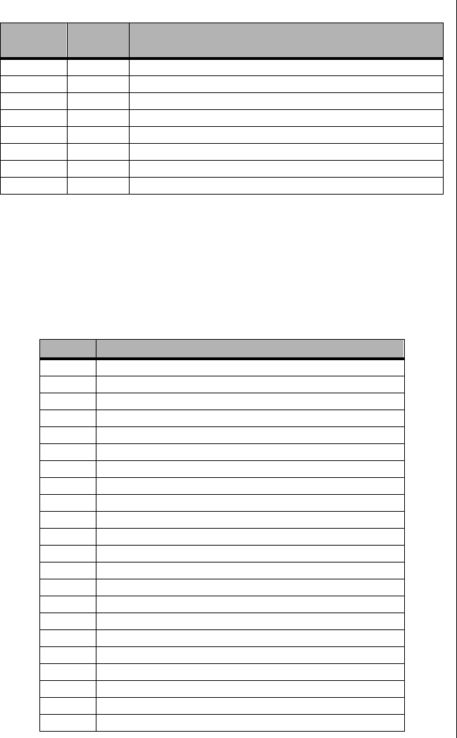
Error and Informational Messages 173
POST Error Codes and Messages
The following error codes and messages are representative of various
conditions BIOS identifies. The exact strings and error numbers may be
different from those listed in Table 35.
BF Check virus and backup reminders
C0 Try to boot with INT 19
D0 Interrupt handler error
D4 Pending interrupt error
D6 Initialize option ROM error
D8 Shutdown error
DA Extended Block Move
DC Shutdown 10 error
Table 35: POST Error Codes
Code Message
0162 BIOS unable to apply BIOS update to processor 1
0163 BIOS unable to apply BIOS update to processor 2
0164 BIOS does not support current stepping for processor 1
0165 BIOS does not support current stepping for processor 2
0200 Failure Fixed Disk
0210 Stuck Key
0211 Keyboard error
0212 Keyboard Controller Failed
0213 Keyboard locked - Unlock key switch
0220 Monitor type does not match CMOS - Run SETUP
0230 System RAM Failed at offset
0231 Shadow RAM Failed at offset
0232 Extended RAM Failed at offset
0250 System battery is dead - Replace and run SETUP
0251 System CMOS checksum bad - Default configuration used
0260 System timer error
0270 Real-time clock error
0297 ECC Memory error in base (extended) memory test in Bank xx
02B2 Incorrect Drive A type - run SETUP
02B3 Incorrect Drive B type - run SETUP
02D0 System cache error - Cache disabled
02F5 DMA Test Failed
Table 34: Port-80h Codes and Beep Codes (Continued)
Port-80
Codes Beep
Codes Error Descriptions
3424.boo Page 173 Wednesday, September 2, 1998 9:23 AM

174 Maintaining and Troubleshooting the Gateway ALR 9200 Server
02F6 Software NMI Failed
0401 Invalid System Configuration Data - run configuration utility
None System Configuration Data Read Error
0403 Resource Conflict
0404 Resource Conflict
0405 Expansion ROM not initialized
0406 Warning: IRQ not configured
0504 Resource Conflict
0505 Expansion ROM not initialized
0506 Warning: IRQ not configured
0601 Device configuration changed
0602 Configuration error - device disabled
8100 Processor 0 failed BIST
8101 Processor 1 failed BIST
8104 Processor 0 Internal Error (IERR) failure
8105 Processor 1 Internal Error (IERR) failure
8106 Processor 0 Thermal Trip failure
8107 Processor 1 Thermal Trip failure
8108 Watchdog Timer failed on last boot, BSP switched
810A Processor 1 failed initialization on last boot
810B Processor 0 failed initialization on last boot
810C Processor 0 disabled, system in uniprocessor mode
810D Processor 1 disabled, system in uniprocessor mode
810E Processor 0 failed FRB Level 3 timer
810F Processor 1 failed FRB Level 3 timer
8110 Server Management Interface failed to function
8120 IOP subsystem is not functional
8150 NVRAM Cleared by Jumper
8151 NVRAM Checksum Error, NVRAM cleared
8152 NVRAM Data Invalid, NVRAM cleared
Table 35: POST Error Codes (Continued)
Code Message
3424.boo Page 174 Wednesday, September 2, 1998 9:23 AM

Appendix A:
Reference
Data
Contents
Specifications....................................................... 176
System I/O Addresses ......................................... 178
Memory Map....................................................... 181
Interrupts.............................................................. 182
Video Modes........................................................ 183
DMA Usage......................................................... 187
3424.boo Page 175 Wednesday, September 2, 1998 9:23 AM

176 Maintaining and Troubleshooting the Gateway ALR 9200 Server
Specifications
System Specifications
The following specifications are for the standard configuration; your
system may contain optional equipment. All specifications are subject to
change.
Summary The system supports up to four Pentium II Xeon
processors running at 400 or 450 MHz. These
processors fit into the slot 2 connectors on the system
board. The system also supports seven expansion
slots, six LVD SCA SCSI drives, onboard narrow and
onboard wide SCSI controller, and a full complement of
I/O ports
Dimensions 19.0”H x 12.25”W x 25.0”D, 85–100 lbs.
Processor Intel Pentium II Xeon processor
Processor speed 400 or 450 MHz
Processor upgrade Slot 2
Cache subsystem 512 KB, 1 MB, or 2 MB level-2 ECC cache
RAM 256-MB standard, 4-GB maximum
BIOS Intel
IDE interfaces One, supporting two IDE devices
Diskette drive 1.44-MB 3.5-inch
I/O Ports Two serial, one parallel, video, mouse, USB, and
keyboard
Mouse/Keyboard Yes
ISA/PCI Expansion
Slots Seven PCI/ One ISA (One of the PCI slots and the ISA
slot are shared)
Certification FCC Class A, TUV, CE, CSA, and UL approved
3424.boo Page 176 Wednesday, September 2, 1998 9:23 AM
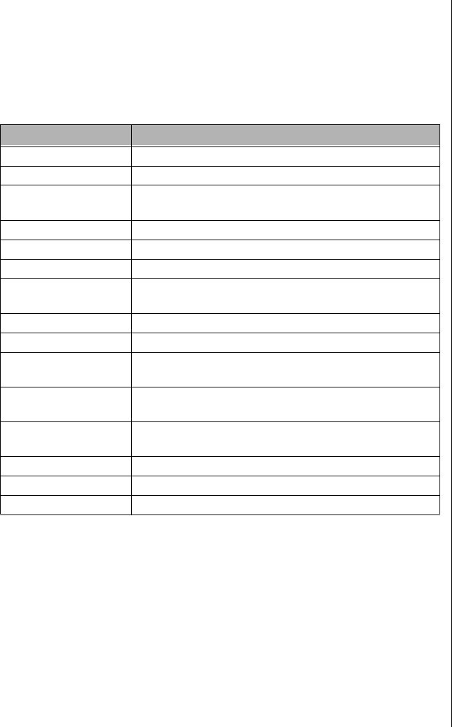
Specifications 177
Environmental Specifications
The following specifications identify maximum environmental
characteristics. At no time should the server run under conditions which
violate these specifications.
Table 36: Environmental Specifications
Variable Requirements
Temperature Maximum rate of change = 10°C per hour
Nonoperating –40° to 70 °C (–55° to 150 °F)
Operating 10° to 35 °C (41° to 95 °F); derated 0.5 °C for every
1000 ft (305 m)
Altitude 10,000 ft max
Humidity
Nonoperating 95% relative (noncondensing) @ 30°C (86°F)
Operating wet bulb Not to exceed 33 °C (91.4 °F) (with diskette drive or
hard disk drive)
Shock
Operating 2.0 g, 11 msec, 1/2 sine
Packaged Operational after 30-inch free fall (cosmetic damage
might occur)
Acoustic noise < 50 dBA w/ two power supplies at 28 °C +/- 2 °C
< 55 dBA w/ three power supplies at 28 °C +/- 2 °C
Electrostatic
discharge (ESD) Tested to 20 kilovolts (kV) per Intel environmental test
specifications; no component damage
AC Input Power
100-120 V∼100-120 V∼, 7.6 A, 50/60 Hz
200-240 V∼200-240 V∼, 3.8 A, 50/60 Hz
3424.boo Page 177 Wednesday, September 2, 1998 9:23 AM

178 Maintaining and Troubleshooting the Gateway ALR 9200 Server
System I/O Addresses
Table 37 shows the location in I/O space of all directly I/O-accessible
registers.
Table 37: System I/O Addresses
Address Resource Device Notes
0000h - 000Fh DMA Controller 1 PIIX4E
0010h - 001Fh DMA Controller 1 PIIX4E Aliased from 0000h - 000Fh
0020h - 0021h Interrupt Controller 1 PIIX4E
0022h - 0023h
0024h - 0025h Interrupt Controller 1 PIIX4E Aliased from 0020h - 0021h
0026h - 0027h
0028h - 0029h Interrupt Controller 1 PIIX4E Aliased from 0020h - 0021h
002Ah - 002Bh
002Ch - 002Dh Interrupt Controller 1 PIIX4E Aliased from 0020h - 0021h
002Eh - 002Fh Super I/O Index and Data
Ports
0030h - 0031h Interrupt Controller 1 PIIX4E Aliased from 0020h - 0021h
0032h - 0033h
0034h - 0035h Interrupt Controller 1 PIIX4E Aliased from 0020h - 0021h
0036h - 0037h
0038h - 0039h Interrupt Controller 1 PIIX4E Aliased from 0020h - 0021h
003Ah - 003Bh
003Ch - 003Dh Interrupt Controller 1 PIIX4E Aliased from 0020h - 0021h
003Eh - 003Fh
0040h - 0043h Programmable Timers PIIX4E
0044h - 004Fh
0050h - 0053h Programmable Timers PIIX4E Aliased from 0040h - 0043h
0054h - 005Fh
0060h, 0064h Keyboard Controller Keyboard chip select from
87307
0061h NMI Status & Control
Register PIIX4E
0063h NMI Status & Control
Register PIIX4E Aliased
0065h NMI Status & Control
Register PIIX4E Aliased
0067h NMI Status & Control
Register PIIX4E Aliased
3424.boo Page 178 Wednesday, September 2, 1998 9:23 AM

System I/O Addresses 179
0070h NMI Mask (bit 7) & RTC
Address (bits 6::0) PIIX4E
0072h NMI Mask (bit 7) & RTC
Address (bits 6::0) PIIX4E Aliased from 0070h
0074h NMI Mask (bit 7) & RTC
Address (bits 6::0) PIIX4E Aliased from 0070h
0076h NMI Mask (bit 7) & RTC
Address (bits 6::0) PIIX4E Aliased from 0070h
0071h RTC Data PIIX4E
0073h RTC Data PIIX4E Aliased from 0071h
0075h RTC Data PIIX4E Aliased from 0071h
0077h RTC Data PIIX4E Aliased from 0071h
0080h - 008Fh DMA Low Page Register PIIX4E
0090h - 0091h DMA Low Page Register PIIX4E Aliased
0092h System Control Port A
(PC-AT control Port) PIIX4E Not aliased in DMA range
0093h - 009Fh DMA Low Page Register PIIX4E Aliased
0094h Video Display Controller
00A0h - 00A1h Interrupt Controller 2 PIIX4E
00A4h - 00A15 Interrupt Controller 2 PIIX4E Aliased
00A8h - 00A19 Interrupt Controller 2 PIIX4E Aliased
00Ach - 00Adh Interrupt Controller 2 PIIX4E Aliased
00B0h - 00B1h Interrupt Controller 2 PIIX4E Aliased
00B2h Advanced Power
Management Control PIIX4E
00B3h Advanced Power
Management Status PIIX4E
00B4h - 00B5h Interrupt Controller 2 PIIX4E Aliased
00B8h - 00B9h Interrupt Controller 2 PIIX4E Aliased
00BCh - 00BDh Interrupt Controller 2 PIIX4E Aliased
00C0h - 00DFh DMA Controller 2 PIIX4E
00F0h Clear NPX error Resets IRQ13
00F8h - 00FFh x87 Numeric Coprocessor
0102h Video Display Controller
0170h - 0177h Secondary Fixed Disk
Controller (IDE) PIIX4E Not used
01F0h - 01F7h Primary Fixed Disk
Controller (IDE) PIIX4E
0200h - 0207h Game I/O Port Not used
Table 37: System I/O Addresses (Continued)
Address Resource Device Notes
3424.boo Page 179 Wednesday, September 2, 1998 9:23 AM

180 Maintaining and Troubleshooting the Gateway ALR 9200 Server
0220h - 022Fh Serial Port A
0238h - 023Fh Serial Port B
0278h - 027Fh Parallel Port 3
02E8h - 02Efh Serial Port B
02F8h - 02FFh Serial Port B
0338h - 033Fh Serial Port B
0370h - 0375h Secondary Diskette
0376h Secondary IDE
0377h Secondary IDE/Diskette
0378h - 037Fh Parallel Port 2
03B4h - 03Bah Monochrome Display Port
03BCh - 03BFh Parallel Port 1 (Primary)
03C0h - 03CFh Video Display Controller
03D4h - 03DAh Color Graphics Controller
03E8h - 03EFh Serial Port A
03F0h - 03F5h Diskette Controller
03F6h - 03F7h Primary IDE - Sec. Diskette
03F8h - 03FFh Serial Port A (Primary)
0400h - 043Fh DMA Controller 1,
Extended Mode Registers PIIX4E
04D0h - 04D1h Interrupt Controllers 1 and
2 Control Register
0678h - 067Ah Parallel Port (ECP)
0778h - 077Ah Parallel Port (ECP)
07BCh - 07BEh Parallel Port (ECP)
0CA0 - CA3h BMC Registers
0CF8h PCI CONFIG_ADDRESS
Register Located in 450NX
0CF9h NBX Turbo and Reset
control PIIX4E
0CFCh PCI CONFIG_DATA
Register Located in 450NX
46E8h Video Display Controller
Table 37: System I/O Addresses (Continued)
Address Resource Device Notes
3424.boo Page 180 Wednesday, September 2, 1998 9:23 AM

Memory Map 181
Memory Map
Table 38: Memory Map
Address Range (hex) Amount Function
0 to 07FFFFh 640 KB DOS region, base system memory
0A0000h to 0BFFFFh 128 KB Video or SMM memory
0C0000h and 0DFFFFh 128 KB Expansion card BIOS and buffer area
0E0000h to 0FFFFFh 128 KB System BIOS
0E0000h to 0EFFFFh 2 MB Extended system BIOS
FC000000h to FFFFFFFFh 64 MB PCI memory space
3424.boo Page 181 Wednesday, September 2, 1998 9:23 AM
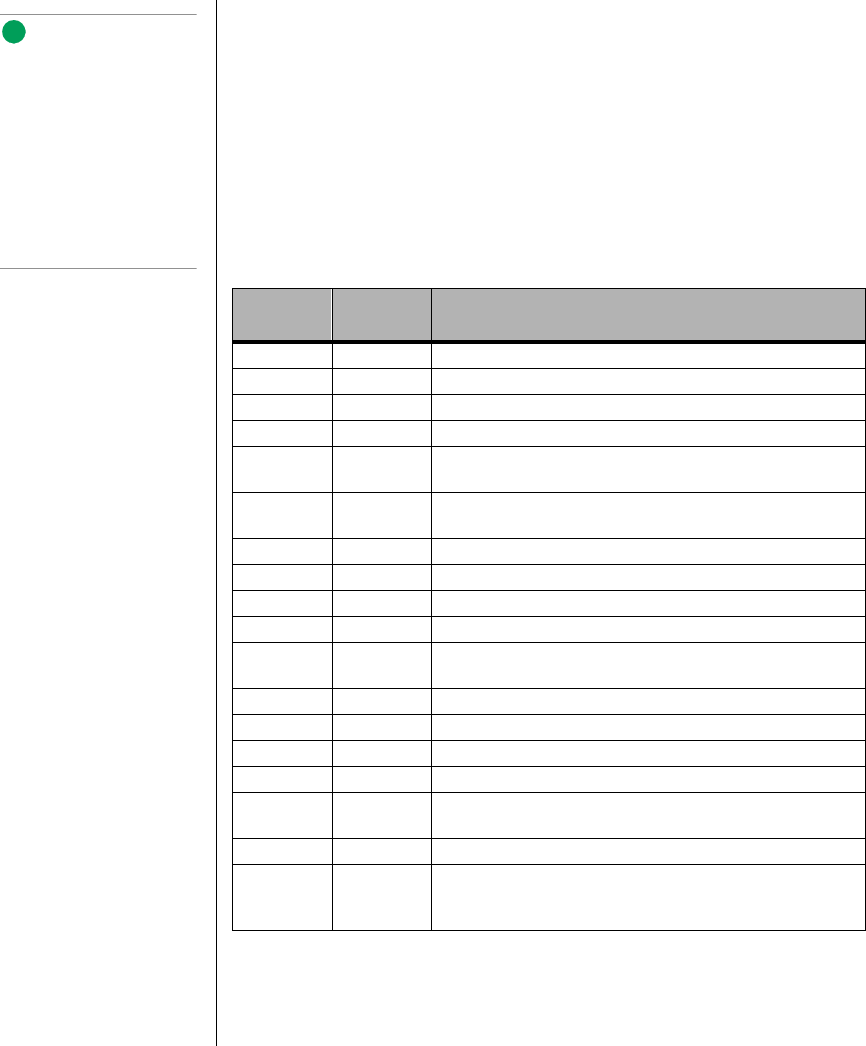
182 Maintaining and Troubleshooting the Gateway ALR 9200 Server
Interrupts
Table 39 suggests a logical interrupt mapping of interrupt sources; it
reflects a typical configuration, but you can change these interrupts. Use
the information to determine how to program each interrupt. The actual
interrupt map is defined using configuration registers in the PIIX4E and the
I/O controller. I/O Redirection Registers in the I/O APIC are provided for
each interrupt signal; the signals define hardware interrupt signal
characteristics for APIC messages sent to local APIC(s).
Table 39: Interrupts
Interrupt I/O APIC
Level Description
INTR INT0 Processor interrupt
NMI N/A NMI from PIC to processor
IRQ1 INT1 Keyboard interrupt
Cascade INT2 Interrupt signal from second 8259 in PIIX4E
IRQ3 INT3 Serial port A or B interrupt from SIO device (you can configure
either)
IRQ4 INT4 Serial port A or B interrupt from SIO device (you can configure
either)
IRQ5 INT5 Parallel port II
IRQ6 INT6 Diskette port
IRQ7 INT7 Parallel port
IRQ8_L INT8 RTC interrupt
IRQ9 INT9 Signal control interrupt (SCI) used by ACPI-compliant
operating system
IRQ10 INT10
IRQ11 INT11
IRQ12 INT12 Mouse interrupt
IRQ13 INT13 Co-processor interrupt
IRQ14 INT14 Compatibility IDE interrupt from primary channel IDE devices
0 and 1
IRQ15 INT15
SMI_L System management interrupt—general purpose indicator
sourced by the PIIX4E and BMC through the PID to the
processors
Note:
If you disable either IDE
controller to free the
interrupt for that controller,
you must physically unplug
the IDE cable from the
system board. Simply
disabling the drive by
configuring the SSU option
does not make the interrupt
available.
3424.boo Page 182 Wednesday, September 2, 1998 9:23 AM
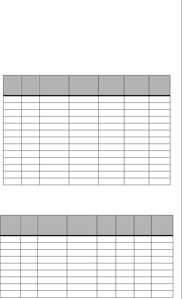
Video Modes 183
Video Modes
The CL-GD5480 integrated video controller provides all standard IBM
VGA modes. With 2 MB of SGRAM standard, the system supports special
Cirrus Logic extended modes. Table 40 and Table 41 list the standard and
extended modes that this implementation supports, including the number of
colors and palette size (e.g., 16 colors out of 256 K colors), resolution, pixel
frequency, and scan frequencies.
Table 40: Standard VGA Modes
Mode
in Hex Bits /
Pixel
Colors
(#/ Palette
Size) Resolution
Pixel
Freq.
(MHz)
Horiz.
Freq.
(kHz)
Vert.
Freq.
(Hz)
0, 1 4 16/256K 360 X 400 14 31.5 70
2, 3 4 16/256K 720 X 400 28 31.5 70
4, 5 4 4/256K 320 X 200 12.5 31.5 70
6 4 2/256K 640 X 200 25 31.5 70
7 4 Mono 720 X 400 28 31.5 70
D 4 16/256K 320 X 200 12.5 31.5 70
E 4 16/256K 640 X 200 25 31.5 70
F 4 Mono 640 X 350 25 31.5 70
10 4 16/256K 640 X 350 25 31.5 70
11 4 2/256K 640 X 480 25 31.5 60
12 4 16/256K 640 X 480 25 31.5 60
12+ 4 16/256K 640 X 480 31.5 37.5 75
13 8 256/256K 320 X 200 12.5 31.5 70
Table 41: Extended VGA Modes
Mode
in Hex Bits /
Pixel
Colors
(#/ Palette
Size) Resolution
Pixel
Freq.
(MHz)
Horiz.
Freq.
(kHz)
Vert.
Freq.
(Hz)
Memory
58, 6A 8 16/256K 800 X 600 36 35.2 56 1MB
58, 6A 8 16/256K 800 X 600 40 37.8 60 1MB
58, 6A 8 16/256K 800 X 600 50 48.1 72 1MB
58, 6A 8 16/256K 800 X 600 49.5 46.9 75 1MB
5C 8 256/256K 800 X 600 36 35.2 56 1MB
5C 8 256/256K 800 X 600 40 37.9 60 1MB
5C 8 256/256K 800 X 600 50 48.1 72 1MB
5C 8 256/256K 800 X 600 49.5 46.9 75 1MB
5C 8 256/256K 800 X 600 56.25 53.7 85 1MB
3424.boo Page 183 Wednesday, September 2, 1998 9:23 AM

184 Maintaining and Troubleshooting the Gateway ALR 9200 Server
5C 8 256/256K 800 X 600 68.2 63.6 100 1MB
5D 8 16/256K
(interlaced) 1024 X 768 44.9 35.5 43 1MB
5D 8 16/256K 1024 X 768 65 48.3 60 1MB
5D 8 16/256K 1024 X 768 75 56 70 1MB
5D 8 16/256K 1024 X 768 78.7 60 75 1MB
5E 8 256/256K 640 X 400 25 31.5 70 1MB
5F 8 256/256K 640 X 480 25 31.5 60 1MB
5F 8 256/256K 640 X 480 31.5 37.9 72 1MB
5F 8 256/256K 640 X 480 31.5 37.5 75 1MB
5F 8 256/256K 640 X 480 36 43.3 85 1MB
5F 8 256/256K 640 X 480 43.2 50.9 100 1MB
60 8 256/256K
(interlaced) 1024 X 768 44.9 35.5 43 1MB
60 8 256/256K 1024 X 768 65 48.3 60 1MB
60 8 256/256K 1024 X 768 75 56 70 1MB
60 8 256/256K 1024 X 768 78.7 60 75 1MB
60 8 256/256K 1024 X 768 94.5 68.3 85 1MB
60 8 256/256K 1024 X 768 113.3 81.4 100 1MB
64 16 64K 640 X 480 25 31.5 60 1MB
64 16 64K 640 X 480 31.5 37.9 72 1MB
64 16 64K 640 X 480 31.5 37.5 75 1MB
64 16 64K 640 X 480 36 43.3 85 1MB
64 16 64K 640 X 480 43.2 50.9 100 1MB
65 16 64K 800 X 600 36 35.2 56 1MB
65 16 64K 800 X 600 40 37.8 60 1MB
65 16 64K 800 X 600 50 48.1 72 1MB
65 16 64K 800 X 600 49.5 46.9 75 1MB
65 16 64K 800 X 600 56.25 53.7 85 1MB
65 16 64K 800 X 600 68.2 63.6 100 1MB
66 16 32K 640 X 480 25 31.5 60 1MB
66 16 32K 640 X 480 31.5 37.9 72 1MB
66 16 32K 640 X 480 31.5 37.5 75 1MB
66 16 32K 640 X 480 36 43.3 85 1MB
66 16 32K 640 X 480 43.2 50.9 100 1MB
67 16 32K 800 X 600 36 35.2 56 1MB
67 16 32K 800 X 600 40 37.8 60 1MB
67 16 32K 800 X 600 50 48.1 72 1MB
67 16 32K 800 X 600 49.5 46.9 75 1MB
Table 41: Extended VGA Modes (Continued)
Mode
in Hex Bits /
Pixel
Colors
(#/ Palette
Size) Resolution
Pixel
Freq.
(MHz)
Horiz.
Freq.
(kHz)
Vert.
Freq.
(Hz)
Memory
3424.boo Page 184 Wednesday, September 2, 1998 9:23 AM

Video Modes 185
67 16 32K 800 X 600 56.25 53.7 85 1MB
67 16 32K 800 X 600 68.2 63.6 100 1MB
68 16 32K
(interlaced) 1024 X 768 44.9 35.5 43 2MB
68 16 32K 1024 X 768 65 48.3 60 2MB
68 16 32K 1024 X 768 75 56 70 2MB
68 16 32K 1024 X 768 78.7 60 75 2MB
68 16 32K 1024 X 768 94.5 68.3 85 2MB
68 16 32K 1024 X 768 113.3 81.4 100 2MB
6C 8 16/256K
(interlaced) 1280 X 1024 75 48 43 1MB
6D 8 256/256K
(interlaced) 1280 X 1024 75 48 43 2MB
6D 8 256/256K 1280 X 1024 108 65 60 2MB
6D 8 256/256K 1280 X 1024 135 80 75 2MB
6D 8 256/256K 1280 X 1024 157.5 91 85 2MB
6E 16 32K 1152 X 864 94.5 63.9 70 2MB
6E 16 32K 1152 X 864 108 67.5 75 2MB
6E 16 32K 1152 X 864 121.5 76.7 85 2MB
6E 16 32K 1152 X 864 143.5 91.5 100 2MB
71 24 16M 640 X 480 25 31.5 60 1MB
71 24 16M 640 X 480 31.5 37.9 72 1MB
71 24 16M 640 X 480 31.5 37.5 75 1MB
71 24 16M 640 X 480 36 43.3 85 1MB
71 24 16M 640 X 480 43.2 50.9 100 1MB
74 16 64K
(interlaced) 1024 X 768 44.9 35.5 43 2MB
74 16 64K 1024 X 768 65 48.3 60 2MB
74 16 64K 1024 X 768 75 56 70 2MB
74 16 64K 1024 X 768 78.7 60 75 2MB
74 16 64K 1024 X 768 94.5 68.3 85 2MB
74 16 64K 1024 X 768 113.3 81.4 100 2MB
78 16 32K 800 X 600 36 35.2 56 1MB
78 24 16M 800 X 600 40 37.8 60 2MB
78 24 16M 800 X 600 50 48.1 72 2MB
78 24 16M 800 X 600 49.5 46.9 75 2MB
78 24 16M 800 X 600 56.25 53.7 85 2MB
78 24 16M 800 X 600 68.2 63.6 100 2MB
7B 8 256/256K
(interlaced) 1600 X 1200 135 62.5 48 2MB
Table 41: Extended VGA Modes (Continued)
Mode
in Hex Bits /
Pixel
Colors
(#/ Palette
Size) Resolution
Pixel
Freq.
(MHz)
Horiz.
Freq.
(kHz)
Vert.
Freq.
(Hz)
Memory
3424.boo Page 185 Wednesday, September 2, 1998 9:23 AM

186 Maintaining and Troubleshooting the Gateway ALR 9200 Server
7B 8 256/256K 1600 X 1200 162 75 60 2MB
7C 8 256/256K 1152 X 864 94.5 63.9 70 1MB
7C 8 256/256K 1152 X 864 108 67.5 75 1MB
7C 8 256/256K 1152 X 864 121.5 76.7 85 1MB
7C 8 256/256K 1152 X 864 143.5 91.5 100 1MB
7D 16 64K 1152 X 864 94.5 63.9 70 2MB
7D 16 64K 1152 X 864 108 67.5 75 2MB
7D 16 64K 1152 X 864 121.5 76.7 85 2MB
7D 16 64K 1152 X 864 143.5 91.5 100 2MB
Table 41: Extended VGA Modes (Continued)
Mode
in Hex Bits /
Pixel
Colors
(#/ Palette
Size) Resolution
Pixel
Freq.
(MHz)
Horiz.
Freq.
(kHz)
Vert.
Freq.
(Hz)
Memory
3424.boo Page 186 Wednesday, September 2, 1998 9:23 AM

DMA Usage 187
DMA Usage
The following table lists the direct memory access (DMA) channels that the
system typically uses and which ones are available for use by add-in
devices.
Table 42: DMA Usage
DMA Resource
0 Cascade
1 Available
2 Floppy Controller
3 Available
4 Redirect Cascade
5 Available
6 Available
7 Available
3424.boo Page 187 Wednesday, September 2, 1998 9:23 AM

188 Maintaining and Troubleshooting the Gateway ALR 9200 Server
3424.boo Page 188 Wednesday, September 2, 1998 9:23 AM

Appendix B:
Regulatory
Compliance
Statements
Contents
Electromagnetic Compatibility........................... 190
FCC Notice.......................................................... 191
Industry Canada Notice....................................... 192
CE Notice............................................................. 192
VCCI Notice........................................................ 193
Australia/New Zealand Notice............................ 193
Declaration of the Manufacturer or Importer..... 194
Safety Compliance .............................................. 194
3424.boo Page 189 Wednesday, September 2, 1998 9:23 AM
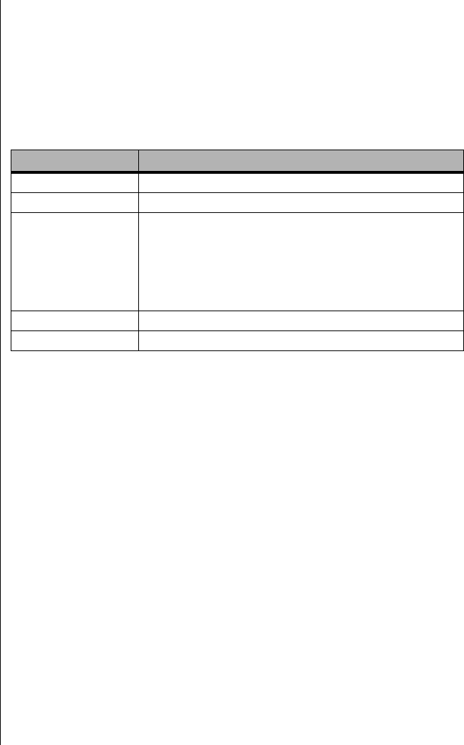
190 Maintaining and Troubleshooting the Gateway ALR 9200
Electromagnetic Compatibility
Table 43 lists the electromagnetic compatibility (EMC) standards to which
the server conforms. The following sections provide notices for several
nations and regions.
Table 43: EMC Standards
Nation or Region Standards
USA: FCC CFR 47 Part 15, Class A
Canada: IC ICES-003 Class A
Europe: EN55022, Class A
EN50082-1
IEC 801-2 ESD Susceptibility
IEC 801-3 Radiated Immunity
IEC 801-4 Electrical Fast Transient
EN61000-3-2 Limit for Harmonic Current Emissions
International: CISPR 22, Class A
Japan: VCCI Class A (CISPR 22 A limit)
3424.boo Page 190 Wednesday, September 2, 1998 9:23 AM

FCC Notice 191
FCC Notice
This device has been tested and found to comply with the limits for a
Class A digital device, pursuant to FCC CFR 47 Part 15 of the FCC rules.
These limits are designed to provide reasonable protection against harmful
interference in a commercial environment. This equipment generates, uses,
and can radiate radio frequency energy and, if not installed and used in
accordance with the instructions, may cause harmful interference to radio
or television reception. However, there is no guarantee that interference will
not occur in a particular installation. If this equipment does cause
interference to radio and television reception, which can be determined by
turning the equipment off and on, the user is encouraged to try to correct
the interference by one or more of the following measures:
•Reorient or relocate the receiving antenna.
•Increase the separation between the equipment and receiver.
•Connect the equipment into an outlet on a circuit different from
that to which the receiver is connected.
•Consult the dealer or an experienced radio/TV technician for help.
•Use shielded I/O cables when operating this equipment.
American Users
Caution!
The Federal
Communications
Commission warns users
that changes or
modifications to the unit not
expressly approved by the
party responsible for
compliance could void the
user’s authority to operate
the equipment.
3424.boo Page 191 Wednesday, September 2, 1998 9:23 AM

192 Maintaining and Troubleshooting the Gateway ALR 9200
Industry Canada Notice
This digital apparatus does not exceed the Class A limits for radio noise
emissions from digital apparatus as set out in the radio interference
regulations of Industry Canada.
Le présent appareil numérique n’émet pas de bruits radioélectriques
dépassant les limites applicables aux appareils numériques de Classe A
prescrites dans le règlement sur le brouillage radioélectrique édicté par
Industrie Canada.
Attention!
Couper le courant avant l’entretien.
CE Notice
This Information Technology Equipment has been tested and found to
comply with the following European directives:
[i] EMC Directive 89/336/EEC amending Directives 92/31/EEC & 93/68/
EEC as per:
- EN 50081-1:1992 according to
EN 55022:1995 Class A
EN 61000-3-2:1995 or EN 60555-2:1986
EN 61000-3-3: 1995
- EN50082-1:1992 according to
EN 61000-4-2:1995 or IEC 801-2:1984
ENV 50140:1994 or IEC 801-3:1984
EN 61000-4-4:1988 or IEC 801-4:1998
[ii] Low Voltage Directive (Safety) 73/23/EEC as per EN 60950
Canadian Users:
European Users:
3424.boo Page 192 Wednesday, September 2, 1998 9:23 AM
VCCI Notice 193
VCCI Notice
This is a Class A product based on the standard of the Voluntary Control
Council for Interference by Information Technology Equipment (VCCI). If
this equipment is used in a domestic environment, radio disturbance may
arise. When such trouble occurs, the user may be required to take corrective
action.
Australia/New Zealand Notice
This device has been tested and found to comply with the limits for a
Class A digital device, pursuant to the Australian/New Zealand standard
AS/NZS 3548 set out by the Spectrum Management Agency.
Japanese Users:
Australian and New Zealand
Users:
3424.boo Page 193 Wednesday, September 2, 1998 9:23 AM
194 Maintaining and Troubleshooting the Gateway ALR 9200
Declaration of the Manufacturer or
Importer
We hereby certify that this product is in compliance with European Union
EMC Directive 89/336/EEC, using standards EN55022 (Class A) and
EN50082-1 and Low Voltage Directive 73/23/EEC, Standard EN60950.
Safety Compliance
Table 44 lists the electromagnetic compatibility (EMC) standards to which
the server conforms. The following sections provide notices for several
nations and regions.
Caution!
This system may include more than one power supply. You must
disconnect all power supplies before servicing.
Table 44: Safety Compliance Standards
Nation or Region Standards
USA: UL 1950 - CSA 950-95, 3rd Edition
Canada: UL certified to CSA 950-95 for Canada (product bears
the single UL mark for U.S. and Canada)
Europe: German GS Mark - ERG to EN60950 2nd Edition, with
amendments
International: NEMKO to IEC950 2nd Edition + Amd 1-4
NEMKO - EN60 950 2nd Edition + Amd 1-4
NEMKO - EMKO-TSE (74-SEC) 207/94
Australian /
New Zealand AS/NZ 3548, Class A limits (CISPR 22)
AS/NZ 3260 (IEC 950 including national AU deviations)
3424.boo Page 194 Wednesday, September 2, 1998 9:23 AM

Index 195
Index
Numerics
3.5-inch drive
diskette, installing 47
diskette, removing 45
diskette, replacing 47
SCSI, hot-swapping 56
32 Bit I/O, Setup field 86
4-way interleaving, memory 23
5.25-inch drive
installing 4, 49
removing 52
A
about this guide viii
access cover
installing 8
removing 3
replacing 8
Access Modes, EMP Console 134
accessing Setup 82
adapter card
installing 63
removing 64
add-in board
installing 63
removing 64
adding an ISA board in the SSU 114
Address Bit Permuting, Setup field 91
addresses, I/O 178
addressing memory 24
Administrator Password is, Setup
field 92
administrator password, access 27
Advanced Chipset Control
Setup field 88
Setup menu 91
advanced menu, Setup menu 87
Assert NMI on AERR, Setup field 94
Assert NMI on BERR, Setup field 94
Assert NMI on PERR, Setup field 94
Assert NMI on SERR, Setup field 94
B
Base I/O Address, Setup field
diskette controller 90
floppy disk controller 90
parallel port 90
serial port A 89
serial port B 90
base memory 24
Base RAM Step, Setup field 91
basic input/output system
see BIOS
battery
replacing 68
system 15
troubleshooting replacement 69
Baud Rate
EMP Console 134
Setup field 95
beep codes
flash update recovery 76
system 170
when there are none 165
bezel
installing 8
opening 4
replacing 8
BIOS
32 Bit I/O field 86
accessing Setup 82
Address Bit Permuting field 91
Administrator Password is field 92
Advanced Chipset Control field 88
advanced chipset control menu 91
advanced menu 87
Assert NMI on AERR field 94
Assert NMI on BERR 94
3424.boo Page 195 Wednesday, September 2, 1998 9:23 AM

196 Maintaining and Troubleshooting the Gateway ALR 9200 Server
Assert NMI on PERR field 94
Assert NMI on SERR field 94
Base I/O Address field, diskette
controller 90
Base I/O Address field, floppy disk
controller 90
Base I/O Address field, parallel
port 90
Base I/O Address field, serial
port A 89
Base I/O Address field, serial
port B 90
Base RAM Step 91
Baud Rate field 95
Boot Device Priority field 95
boot device priority menu 96
boot menu 95
changing the language 101
Clear Event Logging field 94
COM Port Address field 94
Console Redirection field 93
console redirection menu 94
creating upgrade diskette 99
Cylinders field 86
diskette controller field 90
diskette write protect field 93
DMA Channel field, parallel
port 90
Enable Master field, PCI device,
embedded SCSI 88
Enable Master field, PCI
devices 89
Enabled Host Bus Error field 94
Exit Discarding Changes field 97
exit menu 97
Exit Saving Changes field 97
Extended RAM Step field 91
Fixed Disk Boot Sector field 92
Floppy Check field 95
Floppy disk controller field 90
floppy disk drive A 85
floppy disk drive B 85
Floppy Write Protect field 93
Flow Control field 95
Hard Disk Pre-delay field 85
Hard Drive field 95
hard drive menu 96
Heads field 86
I/O Device Configuration field 87
I/O device configuration menu 89
Interrupt field, parallel port 90
Interrupt field, serial port A 89
Interrupt field, serial port B 90
introduction 80
IRQ # field 94
ISA Expansion Aliasing field 91
Key Click field 87
key commands 84
Keyboard auto-repeat delay
field 87
Keyboard auto-repeat rate field 87
Keyboard Features field 85
keyboard features menu 87
L2 Cache field 91
Language field 85
Large Disk Access Mode field 88
Latency Timer field, PCI device,
embedded SCSI 88
Latency Timer field, PCI
devices 89
LBA Mode Control field 86
Legacy Diskette A 85
Legacy Diskette B 85
Load Custom Defaults field 97
Load Setup Defaults field 97
main menu 85
Maximum Capacity field 86
Maximum Number of I2O Drives
field 95
memory 15
Memory Scrubbing field 91
menus 83
Message Timeout Multiplier
field 95
3424.boo Page 196 Wednesday, September 2, 1998 9:23 AM

Index 197
Mode field, parallel port 90
Mode field, serial port B 90
Multi-boot Support field 95
Multi-Sector Transfers field 86
Num Lock field 87
obtaining the upgrade utility 98
Option ROM Scan field, PCI
device, embedded SCSI 88
Option ROM Scan field, PCI
devices 89
Parallel Port field 90
Password on Boot field 92
Pause Before Boot field 88
PCI Configuration field 87
PCI configuration menu 88
PCI Device, Embedded SCSI
field 88
PCI device, embedded SCSI
menu 88
PCI Devices field 89
PCI devices menu 89
Plug and Play OS field 87
preparing for an upgrade 98
Primary Master field 85
primary master menu 86
Primary Slave field 85
primary slave menu 86
Processor Retest field 93
PS/2 Mouse field 90
Read Prefetch for PXB0A field 91
Read Prefetch for PXB0B field 91
record settings 81, 98
recovering 101
Removable Devices field 95
Reset Configuration Data field 87
Restreaming Buffer field 91
Sectors field 86
Secure Mode Boot field 93
Secure Mode Hot Key (Ctrl-Alt- )
field 93
Secure Mode Timer field 92
security menu 92
Serial Port A field 89
Serial Port B field 89
Server Management Mode field 94
server menu 93
Set Administrator Password
field 92
Set User Password field 92
special display items 84
starting Setup 82
System Backup Reminder field 92
System Date field 85
System Event Logging field 94
System Management field 93
system management menu 94
System Time field 85
Transfer Mode field 86
Type field 86
Ultra DMA field 86
upgrading 98, 100
Use Multiprocessor Specification
field 87
User Password is field 92
using 81
Video Blanking field 93
Virus Check Reminder field 92
when to use it 81
BMC, server management 16
bootdiskette check field 95
sequence, setting 29
Setup menu 95
Boot Device Priority
Setup field 95
Setup menu 96
bootable diskette, creating 99
bus ISA 10
PCI 10
USB 20
button, disabling power and reset
buttons 28
3424.boo Page 197 Wednesday, September 2, 1998 9:23 AM

198 Maintaining and Troubleshooting the Gateway ALR 9200 Server
C
cabling
drives 48
IDE drives 49
SCSI drives 49
cache
first level 21
second level, power support 20
second-level 21
carrier, mounting a SCSI drive 55
CD-ROM
bootable drive is not detected 169
drive activity light does not
light 168
central processing unit
see also processor
see CPU
certifications 194
CFG files, using in the FRU and SDR
load utility 149
changing
administrator password in the
SSU 116
boot priority in the SSU 115
user password in the SSU 116
characters are distorted or incorrect
onscreen 166
chassis
closing 7
intrusion monitoring 16, 18
intrusion switch 26
opening 3
checklist, troubleshooting 158
Clear CMOS jumper 13, 74
Clear Event Logging, Setup field 94
clearing
administrator password in the
SSU 116
user password in the SSU 116
Client Configuration, EMP Console 132
closing
chassis 7
electronics bay 7
subchassis 7
system 7
CMOS
memory 13
setting defaults 74
COM Port Address
EMP Console 134
Setup field 94
command line
format, FRU and SDR load
utility 146
parsing, FRU and SDR load
utility 146
command state, EMP Console 130
complimentary metal-oxide
semiconductor
see CMOS
comuter virus notice 155
configuration
memory 25
power supply modules 65
through SSU 105
verifying 158
connect to remote server, EMP
Console 137
connector
auxiliary power 22
back panel I/O 18
diskette drive 13
drives 12
expansion slots 15
external IPMB 18
F16 expansion 18
floppy drive 13
front panel 15
hard drive input 14
ICMB 18
IDE 13
internal USB 15
keyboard 19
main power 21
memory module 16
mouse 19
3424.boo Page 198 Wednesday, September 2, 1998 9:23 AM

Index 199
narrow SCSI 12
parallel port 19
processor slots 21
SCSI, narrow 12
SCSI, wide 12
serial ports 19
SMBus 18
SMM 18
speaker 14
system board 10
USB 20
video 18
VRMs 20
wake-on-LAN technology 14
wide SCSI 12
Console Redirection
EMP Console menu 134
Setup field 93
Setup menu 94
Console Type, EMP Console 134
controlled access, SSU 28
controller
drives 12
graphics 10
SCSI narrow 10
SCSI wide 10
video 10
controlling the server through the EMP
Console 136
conventions used in this guide ix
cooling
installing fan for correct airflow 62
record airflow when removing
fan 59
countdown codes 170
CPUfirst-level cache 21
heatsink 32, 36
installing 34, 38
installing second 36
MMX technology 21
multiprocessor capability 21
power support 20
removing 33
removing termination card 36
replacing 32
second-level cache 21
see also processor
slots 21
supported 10
customizing the SSU 109
Cylinders, Setup field 86
D
defining an ISA board in the SSU 113
diagnostic testing, preparing the
system 162
DIMM
banks 23
installation sequence 24
installing 43
removing 41
supported 10, 23
Direct Connect Configuration, EMP
Console 133
direct memory access
see DMA
diskette
activity light does not light 167
connector 13
controller field, Setup 90
creating BIOS upgrade diskette 99
creating bootable 99
diskette check Setup field 95
installing 47
removing 45
replacing 47
write protect monitoring 17
write protect, Setup field 93
write protection summary 28
DMA Channel, Setup field, parallel
port 90
DMA usage 187
document conventions ix
DRAM, memory type 10
3424.boo Page 199 Wednesday, September 2, 1998 9:23 AM

200 Maintaining and Troubleshooting the Gateway ALR 9200 Server
drive5.25-inch, installing 4
cabling considerations 48
CD-ROM activity light does not
light 168
controllers and connectors 12
fans, high-power SCSI hard
drives 57
floppy drive A field 85
floppy drive B field 85
hard disk activity light does not
light 168
hard drive input LED connector 14
heatsinks on high-power SCSI hard
drives 54
IDE, cabling 49
installing a 5.25-inch drive 49
installing the diskette drive 47
removing a 5.25-inch drive 52
removing the diskette drive 45
replacing the diskette drive 47
SCSI
cabling 49
drive error LEDs 56
hot-swapping 56
mounting in carrier 55
drivers, video, installing 77
dual in-line memory module
see DIMM
dynamic random access memory
see DRAM
E
ECC, memory type 10
editing resources in the SSU 115
EDO, memory type 10
electromagnetic compatibility
see EMC
electromagnetic interference
see EMI
electronics bay
closing 7
defined 5
opening 5
EMC
compatibility 190
compliance with standards 194
emergency management port
see EMP
EMI shield, removing 50
EMP Console
Baud Rate 134
Client Configuration 132
COM Port Address 134
command state 130
connect to remote server 137
console redirection menu 134
Console Type 134
Direct Connect Configuration 133
EMP Access Modes 134
EMP Direct Connect/Modem
Mode 134
EMP Password 133
EMP Restricted Mode Access 134
Flow Control 134
FRU Viewer 144
FRU Viewer options 144
how it works 130
introduction 129
main menu 136
main window 134
management plug-ins 141
Modem Configuration 133
phonebook 140
power on/off remote server 138
redirect state 131
requirements 132
reset remote server 139
SDR Viewer 143
SDR Viewer options 143
SEL Viewer 141
SEL Viewer options 142
Server Configuration 133
server control operations 136
setting up the server 133
status bar 135
3424.boo Page 200 Wednesday, September 2, 1998 9:23 AM

Index 201
system management menu 133
toolbar 135
EMP Direct Connect/Modem Mode,
EMP Console 134
EMP Restricted Mode Access, EMP
Console 134
Enable Master
Setup field, PCI device, embedded
SCSI 88
Setup field, PCI devices 89
Enabled Host Bus Error, Setup field 94
environmental specifications 177
errorcodes 173
fan failure 16
memory 23
messages 170, 173
overtemperature 16
overvoltage 16
single-bit memory errors 40
error correcting code
see ECC
ESDsee static electricity
Exit Discarding Changes, Setup field 97
Exit Saving Changes, Setup field 97
exit, Setup menu 97
exiting
FRU and SDR load utility 150
SSU 124
expansion card
adding an ISA card in the SSU 114
defining an ISA card in the
SSU 113
installing 63
removing 64
removing an ISA card in the
SSU 114
testing a video controller 165
expansion slot
connectors 15
ISA 15
PCI 16
PCI-A 16
PCI-B 16
shared 16
extended data output
see EDO
extended memory 24
Extended RAM Step, Setup field 91
extended VGA modes supported 183
external IPMB connector 18
F
F16 expansion connector 18
fan failure monitoring 16
installing for high-power SCSI
drives 57
installing system fan 62
installing, high-power drives 57
installing, power supply bay 57
removing a system fan 59
removing fan assembly 60
removing foam covers 60
speed monitoring 18
fault resilient boot
see FRB
features
software security 28
system board 10
field replaceable unit
see FRU
Firmware Update utility
running 151
using 151
first-level cache 21
Fixed Disk Boot Sector, Setup field 92
flash BIOS
beep codes for recovery 76
memory 15
recovering 101
recovery if failed 75
upgrading 98, 100
Floppy check, Setup field 95
Floppy disk controller, Setup field 90
3424.boo Page 201 Wednesday, September 2, 1998 9:23 AM

202 Maintaining and Troubleshooting the Gateway ALR 9200 Server
floppy drive, connector 13
Floppy Write Protect, Setup field 93
Flow Control
EMP Console 134
Setup field 95
foam covers, removing 60
format
command line, FRU and SDR load
utility 146
conventions ix
four-way interleaving, memory 23
FRB, system management control 17
front bezel
installing 8
lock/unlock 17
opening 4
replacing 8
front panel connector 15
FRU and SDR load utility 145
cleaning up and exiting 150
command line format 146
displaying usage data 147
parsing the command line 146
running 146
using CFG files 149
what you need to do 145
when to run 145
FRU Manager Add-in, SSU 122
FRU Viewer
EMP Console 144
options 144
FUUsee Firmware Update utility
G
graphics, controller 10
guidelines, troubleshooting 158
H
Hard Disk Pre-delay, Setup field 85
Hard Drive
input connector 14
Setup field 95
Setup menu 96
hard drive
fans for high-power drives 57
heatsinks on high-power drives 54
Heads, Setup field 86
heatsink
high-power drives 54
processor 32, 36
high-power drives
fans 57
heatsinks 54
hot-swapping
power supply modules 65
SCSI drive 56
how the EMP Console works 130
how to run the FRU and SDR load
utility 145
I
I/O addresses, system 178
back panel connectors 18
ports 10
I/O Device Configuration
Setup field 87
Setup menu 89
ICMB connector 18
IDE connectors 13
important safety instructions x
industry standard architecture
see ISA
informational messages 170
input/output
see I/O
installing
5.25-inch drives 4, 49
access cover 8
adapter card 63
add-in board 63
bezel 8
DIMMs 43
DIMMs in sequence 24
diskette drive 47
expansion card 63
3424.boo Page 202 Wednesday, September 2, 1998 9:23 AM

Index 203
fan, high power drives 57
fan, power supply bay 57
floppy drive 47
front bezel 8
memory module 44
power supply module 67
processor 34, 38
second processor 36
side panel 8
system fan 62
video drivers 77
intelligent chassis management port
see ICMB
interperipheral management bus
see IPMB
Interrupt
Setup field, parallel port 90
Setup field, serial port A 89
Setup field, serial port B 90
system 182
intrusion detection, monitoring 18
IPMB connector, external 18
IRQ #, Setup field 94
ISA adding a board in the SSU 114
bus 10
card support 15
defining a board in the SSU 113
expansion slot 15
memory holes 24
removing a board in the SSU 114
ISA Expansion Aliasing, Setup field 91
J
jumper
Clear CMOS 13, 74
function 72
location 72
Password Clear 14, 75
Recovery Boot 14, 75
set CMOS to system defaults 74
setting 73
system board 13
K
Key Click, Setup field 87
key commands, Setup 84
keyboard
booting without one 29
port 19
Keyboard auto-repeat delay, Setup
field 87
Keyboard auto-repeat rate, Setup
field 87
Keyboard Features
Setup field 85
Setup menu 87
L
L2 Cache, Setup field 91
LAN, wake-on-LAN connector 14
Language
changing in the BIOS 101
Setup field 85
Large Disk Access Mode, Setup field 88
Latency Timer
Setup field, PCI device 89
Setup field, PCI device, embedded
SCSI 88
launching a task, SSU 111
LBA Mode Control, Setup field 86
LEDhard drive input connector 14
monitoring for proper
operation 163
SCSI drive error 56
Legacy Diskette A, Setup field 85
Legacy Diskette B, Setup field 85
light emiting diode
see LED
Load Custom Defaults, Setup field 97
Load Setup Defaults, Setup field 97
local area network
see LAN
locks
software, security 26
3424.boo Page 203 Wednesday, September 2, 1998 9:23 AM

204 Maintaining and Troubleshooting the Gateway ALR 9200 Server
logical block addressing
see LBA
low voltage differential
see LVD
LVD, SCSI drives 10
M
main menu
EMP Console 136
Setup menu 85
main window, EMP Console 134
management plug-ins, EMP
Console 141
Maximum Capacity, Setup field 86
Maximum Number of I2O Drives, Setup
field 95
memory
addressing 24
banks 23
base 24
CMOS 13
configuring 25
DRAM 10
error correction 23
extended 24
flash BIOS 15
four way interleaving 23
holes 24
installing DIMMs 43
installing memory module 44
map, system 181
module 23
module connector 16
removing DIMMs 41
removing the memory module 40
sequenced DIMM installation 24
supported 10
supported DIMMs 23
video, installed 10
Memory Scrubbing, Setup field 91
menus, Setup 83
Messaage Timeout Multiplier, Setup
field 95
Mode
Setup field, parallel port 90
Setup field, serial port B 90
Modem configuration, EMP
Console 133
modifying resources in the SSU 114
modules, power supply 65
monitor, supported 19
monitoring
chassis intrusion 18
fan speeds 18
POST 163
temperature 18
voltages 18
mouse, port 19
Multiboot Options Add-in, SSU 115
Multi-boot Support, Setup field 95
Multi-Sector Transfers, Setup field 86
N
narrow SCSI, connector 12
network problems, troubleshooting 168
NMI, generating 17
no characters appear onscreen 165
non-maskable interrupt
see NMI
notice, computer viruses 155
Num Lock, Setup field 87
O
opening
bezel 4
electronics bay 5
front bezel 4
subchassis 5
system 3
operating system, confirming load 164
Option ROM Scan
Setup field, PCI device, embedded
SCSI 88
Setup field, PCI devices 89
overtemperature, monitoring 16
overvoltage, monitoring 16
3424.boo Page 204 Wednesday, September 2, 1998 9:23 AM

Index 205
P
Parallel Port
connector 19
Setup field 90
password
administrator
changing in the SSU 116
clearing in the SSU 116
setting in the SSU 116
Administrator Password is Setup
field 92
adminsitrator 28
both user and administrator
passwords set 27
clearing by jumper 75
EMP Password 133
only user password set 27
Password on Boot Setup field 92
Set Administrator Password Setup,
field 92
Set User Password Setup field 92
system access control 29
user changing in the SSU 116
clearing in the SSU 116
setting in the SSU 116
User Password is Setup field 92
using 27
Password Clear jumper 14, 75
Password on Boot, Setup field 92
Pause Before Boot, Setup field 88
PCDiagnostics, using 163
PCI buses 10
expansion slots 16
installation tips 168
PCI-A expansion slots 16
PCI-B expansion slots 16
PCI Configuration
Setup field 87
Setup menu 88
PCI Device, Embedded SCSI
Setup field 88
Setup menu 88
PCI Devices
Setup field 89
Setup menu 89
peripheral component interconnect
see PCI
phonebook, EMP Console 140
Plug and Play OS, Setup field 87
port I/O 10
keyboard 19
mouse 19
USB 20
video 18
Port 80h codes 170
POST
codes 170, 173
messages 170, 173
monitoring 163
using 127
power
auxiliary power connector 22
configuration of modules 65
disabling power button 28
hot-swapping modules 65
installing a power supply
module 67
installing fan in power supply
bay 57
light does not light 164
main power connectors 21
module retention clip 66
power share board 65
removing a module 66
replacing a power supply
module 67
supply characteristics 65
Power on/off remote server, EMP
Console 138
3424.boo Page 205 Wednesday, September 2, 1998 9:23 AM

206 Maintaining and Troubleshooting the Gateway ALR 9200 Server
precautions, static electricity 2
preventing static electricity 2
Primary Master
Setup field 85
Setup menu 86
Primary Slave
Setup field 85
Setup menu 86
problem-solving procedures 162
processor
first-level cache 21
heatsink 32, 36
installing 34, 38
installing second 36
MMX technology 21
multiprocessor capability 21
power support 20
removing 33
removing termination card 36
replacing 32
second-level cache 21
slots 21
supported 10
Processor Retest, Setup field 93
PS/2 Mouse, Setup field 90
R
RAM, supported 10
random access memory
see RAM
RCA window
SSU 112
using in SSU 112
Read Prefetch for PXB0A, Setup
field 91
Read Prefetch for PXB0B, Setup
field 91
rebooting the system 159
Recovery Boot jumper 14, 75
recovery, flash BIOS 101
redirect state, EMP Console 131
regulatory specifications
electromagnetic compatibility 190
safety compliance 194
Removable Devices, Setup field 95
removing
5.25-inch drive 52
access cover 3
adapter card 64
add-in board 64
DIMMs 41
diskette drive 45
EMI shield 50
expansion card 64
fan assembly 60
foam covers 60
foam fan cover 60
ISA board in the SSU 114
memory module 40
power supply module 66
processor 33
side panel 3
system fan 59
termination card 36
replacing
access cover 8
battery 68
bezel 8
diskette drive 47
front bezel 8
power supply module 67
processor 32
side panel 8
requirements, EMP Console 132
reset button, disabling 28
Reset Configuration Data, Setup
field 87
reset remote server, EMP Console 139
resetting the system 159
resolution, video, supported 19
resource configuration add-in
see RCA
3424.boo Page 206 Wednesday, September 2, 1998 9:23 AM

Index 207
resources
DMA usage 187
editing in the SSU 115
I/O addresses 178
interrupts 182
memory map 181
modifying in the SSU 114
usage shown in the SSU 115
video modes supported 183
restarting the system 159
Restreaming Buffer, Setup field 91
retention clip, power supply module 66
running
Firmware Update utility 151
SSU locally 107
SSU remotely 107
S
safety
agency certification 194
compliance 194
important instructions x
static electricity precautions 2
SCSI
connectors 12
controllers 10
drive error LEDs 56
fans on high-power drives 57
heatsinks on high-power drives 54
hot-swapping a drive 56
mounting drive on carrier 55
narrow connector 12
SE 10
using fans for high-power drives 57
wide connector 12
SDR Manager Add-in, SSU 120
SDR Viewer
EMP Console 143
options 143
SDRR, storing system management
data 16
SE, SCSI 10
SEC, processor cartridge 10
second-level cache 21
Sectors, Setup field 86
secure boot mode, summary 28
secure mode 17
Secure Mode Boot, Setup field 93
Secure Mode Hot Key (Ctrl-Alt- ), Setup
field 93
Secure Mode Timer, Setup field 92
secure mode, setting up in the SSU 27
security
Administrator Password is Setup
field 92
adminstrator password 28
boot without keyboard 29
both user and administrator
passwords set 27
chassis intrusion switch 26
clearing passwords 75
control SSU access 28
disable diskette writes 28
disabling power and reset
buttons 28
diskette write protect
monitoring 17
diskette write protection, Setup
field 93
EMP Password 133
Fixed Disk Boot Sector Setup
field 92
Floppy Write Protect Setup field 93
front panel lock/unlock 17
only user password set 27
options in the SSU 117
Password on Boot Setup field 92
secure boot mode 28
secure mode 27
Secure Mode Boot Setup field 93
secure mode control 17
Secure Mode Hot Key (Ctrl-Alt- )
Setup field 93
Secure Mode Timer Setup field 92
3424.boo Page 207 Wednesday, September 2, 1998 9:23 AM

208 Maintaining and Troubleshooting the Gateway ALR 9200 Server
Set Administrator Password Setup
field 92
set user password 29
Set User Password Setup field 92
setting the boot sequence 29
setting up in BIOS 26
setting up in SSU 26
Setup menu 92
software features 28
software locks 26
SSU add-in 116
timeout 28
User Password is Setup field 92
using passwords 27
video blanking 17
Video Blanking Setup field 93
Security Add-in, SSU 116
SEL Viewer
EMP Console 141
options 142
SEL Viewer Add-in, SSU 118
sensor data record
see SDR
sensor data record repository
see SDRR
Serial Port A, Setup field 89
Serial Port B, Setup field 89
serial ports 19
server
setting up for EMP 133
Setup menu 93
Server Configuration, EMP
Console 133
server control, EMP Console
operations 136
Server Management Mode, Setup
field 94
server management module
see SMM
server management, managing the
server 10
Set Administrator Password, Setup
field 92
Set User Password, Setup field 92
setting
administrator password in the
SSU 116
CMOS defaults 74
floppy drive A 85
floppy drive B 85
jumpers 73
recording BIOS settings 98
recording settings 81
server for EMP 133
user password in the SSU 116
Setup
access 82
advanced chipset control menu 91
advanced menu 87
boot device priority menu 96
boot menu 95
console redirection menu 94
exit menu 97
fields
32 Bit I/O 86
Address Bit Permuting 91
Administrator Password is 92
Advanced Chipset Control 88
Assert NMI on AERR 94
Assert NMI on BERR 94
Assert NMI on PERR 94
Assert NMI on SERR 94
Base I/O Address, diskette
controller 90
Base I/O Address, floppy disk
controller 90
Base I/O Address, parallel
port 90
Base I/O Address, serial
port A 89
Base I/O Address, serial
port B 90
Base RAM Step 91
Baud Rate 95
Boot Device Priority 95
Clear Event Logging 94
3424.boo Page 208 Wednesday, September 2, 1998 9:23 AM

Index 209
COM Port Address 94
Console Redirection 93
Cylinders 86
diskette check 95
diskette controller 90
diskette write protect 93
DMA Channel, parallel
port 90
Enable Master, PCI device,
embedded SCSI 88
Enable Master, PCI devices 89
Enabled Host Bus Error 94
Exit Discarding Changes 97
Exit Saving Changes 97
Extended RAM Step 91
Fixed Disk Boot Sector 92
Floppy Check 95
Floppy disk controller 90
Floppy Write Protect 93
Flow Control 95
Hard Disk Pre-delay 85
Hard Drive 95
Heads 86
I/O Device Configuration 87
Interrupt, parallel port 90
Interrupt, serial port A 89
Interrupt, serial port B 90
IRQ # 94
ISA Expansion Aliasing 91
Key Click 87
Keyboard auto-repeat
delay 87
Keyboard auto-repeat rate 87
Keyboard Features 85
L2 Cache 91
Language 85
Large Disk Access Mode 88
Latency Timer, PCI device,
embedded SCSI 88
Latency Timer, PCI
devices 89
LBA Mode Control 86
Legacy Diskette A 85
Legacy Diskette B 85
Load Custom Defaults 97
Load Setup Defaults 97
Maximum Capacity 86
Maximum Number of I2O
Drives 95
Memory Scrubbing 91
Message Timeout
Multiplier 95
Mode, parallel port 90
Mode, serial port B 90
Multi-boot Support 95
Multi-Sector Transfers 86
Num Lock 87
Option ROM Scan, PCI
device, embedded SCSI 88
Option ROM Scan, PCI
devices 89
Parallel Port 90
Password on Boot 92
Pause Before Boot 88
PCI Configuration 87
PCI Device, Embedded
SCSI 88
PCI Devices 89
Plug and Play OS 87
Primary Master 85
Primary Slave 85
Processor Retest 93
PS/2 Mouse 90
Read Prefetch for PXB0A 91
Read Prefetch for PXB0B 91
Removable Devices 95
Reset Configuration Data 87
Restreaming Buffer 91
Sectors 86
Secure Mode Boot 93
Secure Mode Hot Key (Ctrl-
Alt- ) 93
Secure Mode Timer 92
Serial Port A 89
Serial Port B 89
Server Management Mode 94
3424.boo Page 209 Wednesday, September 2, 1998 9:23 AM

210 Maintaining and Troubleshooting the Gateway ALR 9200 Server
Set Administrator
Password 92
Set User Password 92
System Backup Reminder 92
System Date 85
System Event Logging 94
System Management 93
System Time 85
Transfer Mode 86
Type 86
Ultra DMA 86
Use Multiprocessor
Specification 87
User Password is 92
Video Blanking 93
Virus Check Reminder 92
floppy drive A field 85
floppy drive B field 85
hard drive menu 96
I/O device configuration menu 89
introduction 80
key commands 84
keyboard features menu 87
main menu 85
menus 83
PCI configuration menu 88
PCI device, embedded SCSI
menu 88
PCI devices menu 89
primary master menu 86
primary slave menu 86
record settings 81
security menu 92
server menu 93
special display items 84
starting 82
system management menu 94
using 81
when to use 81
shared expansion slots 16
sharing power between modules 65
side panel
installing 8
removing 3
replacing 8
single edge contact
see SEC
single ended SCSI
see SE, SCSI
slot II connector, system board 21
small computer systems interface
see SCSI
SMBus connector 18
SMI, generating 17
SMM connector 18
software
problems with applications 169
security features 28
trouble with new 160
solving problems 159, 162
speaker, connector 14
special display items in Setup 84
specific problems
bootable CD_ROM is not
detected 169
CD-ROM activity light does not
light 168
characters are distorted or
incorrect 166
diskette drive activity light does not
light 167
hard disk activity light does not
light 168
network problems 168
no beep codes 165
no characters appear onscreen 165
PCI installation tips 168
power light does not light 164
problems with applications 169
system cooling fans do not rotate
properly 166
troubleshooting 164
3424.boo Page 210 Wednesday, September 2, 1998 9:23 AM

Index 211
specifications
environmental 177
system 176
SSUaccess control 28
adding an ISA board 114
changing the administrator
password 116
changing the user password 116
clearing the administrator
password 116
clearing the user password 116
customizing 109
defining an ISA board 113
editing resources 115
exiting 124
FRU Manager Add-in 122
how to run 106
introduction 104
launching a task 111
modifying resources 114
Multiboot Options Add-in 115
RCA Window 112
removing an ISA board 114
resource usage 115
running locally 107
running remotely 107
SDR Manager Add-in 120
Security Add-in 116
security options 117
SEL Viewer Add-in 118
setting security 26
setting the administrator
password 116
setting the user password 116
starting 108
using 105
using the RCA window 112
when to use 81, 105
standard VGA modes supported 183
starting
Setup 82
SSU 108
static electricity precautions 2
status bar, EMP Console 135
subchassis
closing 7
defined 5
opening 5
super video graphics array
see SVGA
supported
CPUs 10
DIMMs 10
extended VGA modes 183
memory 10
monitors 19
processors 10
RAM 10
standard VGA modes 183
video modes 183
video resolutions 19
SVGA
supported monitors 19
video controller 10
switch, chassis intrusion 26
Symbios SCSI utlity, using 152
system
access 3
access control 29
battery 15
board, connectors 10
board, illustration 10
closing 7
cooling fans do not rotate
properly 166
I/O addresses 178
I/O ports 10
installing fans 62
interrupts 182
intrusion monitoring 16
jumpers 13
memory map 181
opening 3
preparing for diagnostic testing 162
removing fans 59
3424.boo Page 211 Wednesday, September 2, 1998 9:23 AM

212 Maintaining and Troubleshooting the Gateway ALR 9200 Server
restarting 159
specifications 176
system board features 10
trouble at startup 159
troubleshooting new problems 161
System Backup Reminder, Setup
field 92
system board management controller
see BMC
System Date, Setup field 85
system event log
see SEL
System Event Logging, Setup field 94
System Management
Setup field 93
Setup menu 94
system management interrupt
see SMI
system management menu, EMP
Console 133
system setup utility
see SSU
System Time, Setup field 85
T
technical specifications 176
temperature, monitoring 16, 18
termination card, removing 36
testing
add-in video controller 165
preparing for diagnostics 162
text formatting in this guide ix
timeout, security 28
toolbar, EMP Console 135
Transfer Mode, Setup field 86
troubleshooting
bootable CD-ROM is not
detected 169
CD-ROM drive activity light does
not light 168
characters are distorted or
incorrect 166
checklist 158
confirming operating system
load 164
diskette drive activity light does not
light 167
flash update recovery 75
flash update recovery beep
codes 76
guidelines 158
hard disk drive activity light does
not light 168
initial system startup 159
network problems 168
new battery 69
no beep codes 165
no characters appear onscreen 165
PCI installation tips 168
power light does not light 164
problems with applications 169
problems-solving procedures 162
running new software 160
solving problems 159
specific problems 164
system cooling fans do not rotate
properly 166
system has been running fine 161
system LED failures 163
Type, Setup field 86
U
Ultra DMA, Setup field 86
universal serial bus
see USB
upgrade
BIOS 98, 100
creating bootable diskette 99
obtaining the BIOS upgrade
utility 98
usage data, FRU and SDR load
utility 147
USBbus speed 20
internal connector 15
port 20
3424.boo Page 212 Wednesday, September 2, 1998 9:23 AM

Index 213
Use Multiprocessor Specification, Setup
field 87
User Password is, Setup field 92
user password, access 27
using
CFG files with the FRU and SDR
load utility 149
Firmware Update utility 151
FRU and SDR load utility 146
passwords 27
PCDiagnostics 163
POST 127
resources from the SSU 115
Setup 81
SSU 105
Symbios SCSI utility 152
utility
FRU and SDR load 145
obtaining to upgrade BIOS 98
V
verifying the configuration 158
VGA
extended modes supported 183
standard modessupported 183
video
blanking 17
connector 18
controller 10
installing drivers 77
memory installed 10
modes supported 183
supported resolutions 19
SVGA controller 10
Video Blanking, Setup field 93
Virus Check Reminder, Setup field 92
virus notice 155
voltage monitoring 16, 18
voltage regulator module
see VRM
VRM
connectors 20
second-level cache 20
W
wake-on-LAN technology connector 14
when to run the FRU and SDR load
utility 145
when to run the SSU 105
wide SCSI connectors 12
3424.boo Page 213 Wednesday, September 2, 1998 9:23 AM

214 Maintaining and Troubleshooting the Gateway ALR 9200 Server
3424.boo Page 214 Wednesday, September 2, 1998 9:23 AM
