Ge High Pressure Ratio Compressors Brochure
Ge-High-Pressure-Ratio-Compressors-Brochure-648663 ge-high-pressure-ratio-compressors-brochure-648663
2015-03-09
: Ge Ge-High-Pressure-Ratio-Compressors-Brochure-648663 ge-high-pressure-ratio-compressors-brochure-648663 ge pdf
Open the PDF directly: View PDF ![]() .
.
Page Count: 6

GE Oil & Gas
High Pressure
Ratio Compression
Innovative HPRC technology in a
lightweight, compact and
cost-efficient package
A whole new way
of thinking about
compression
GE’s HPRC technology is
based on an innovative
architecture that combines
unshrouded and shrouded
impellers on a single high-
speed shaft to achieve
pressure ratios and efficiency
levels higher than other
available technologies.
As result of the increased
head per stage, HPRC units
have a shorter bearing span
that reduces the number of
casings required. Applications
that would typically require
multiple compressor bodies
will only need one with HPRC.
Individual HPRC units are
already smaller and lighter
than traditional compressors,
and the elimination of units
per train is another giant
improvement in overall
plant footprint, reliability,
availability and weight.

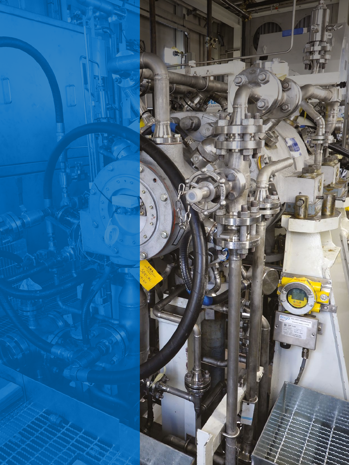
Comprehensive testing
The rigorous validation program comprised
a variety of tests on machine integrity,
compressor performance, operability and
response to upset conditions:
• Full load compressor performance
• Extensive rotor-dynamic test campaign
• Aeromechanical test at different suction
pressure levels
• Test of upset conditions such as
emergency shut-down and exploration
of surge region
Smaller package
Bigger results
HPRC technology is applicable to many gas
processes and is well suited to both low
and medium molecular weight mixtures. It
delivers high reliability and efficiency: from
reduced weight and easier installation,
to minimized footprint, lower power
consumption and reduced maintenance.
HPRC advantages
• Up to 50% smaller train footprint
than traditional configuration
• Up to 30% lighter weight
• Up to 5% less power consumption
• Simplified installation
• Higher reliability & availability
due to auxiliary equipment reduction
(eg: DGS, lubrication)
• Lower downtime and easier
maintenance
• Wide revamping flexibility
Key features
Centrifugal compressor Up to 3 sections (@ 2 intercooler) in 1 casing
Max. operating pressure 400 bar (5,800 PSI)
Pressure ratio Up to 30:1 (with natural gas mol. weight 20)
Max flow 300,000 Am3/h (254 MMSCF/D)
Arrangement Between bearings
Gear selection Parallel shaft for Gear ratio < 9
Epicyclic gear ratio > 9 & power < 35 MW
Driver types All
Dry gas seal Standard
Bearings Standard
Availability +0.3% vs. standard machine
Reliability +0.2% vs. standard machine
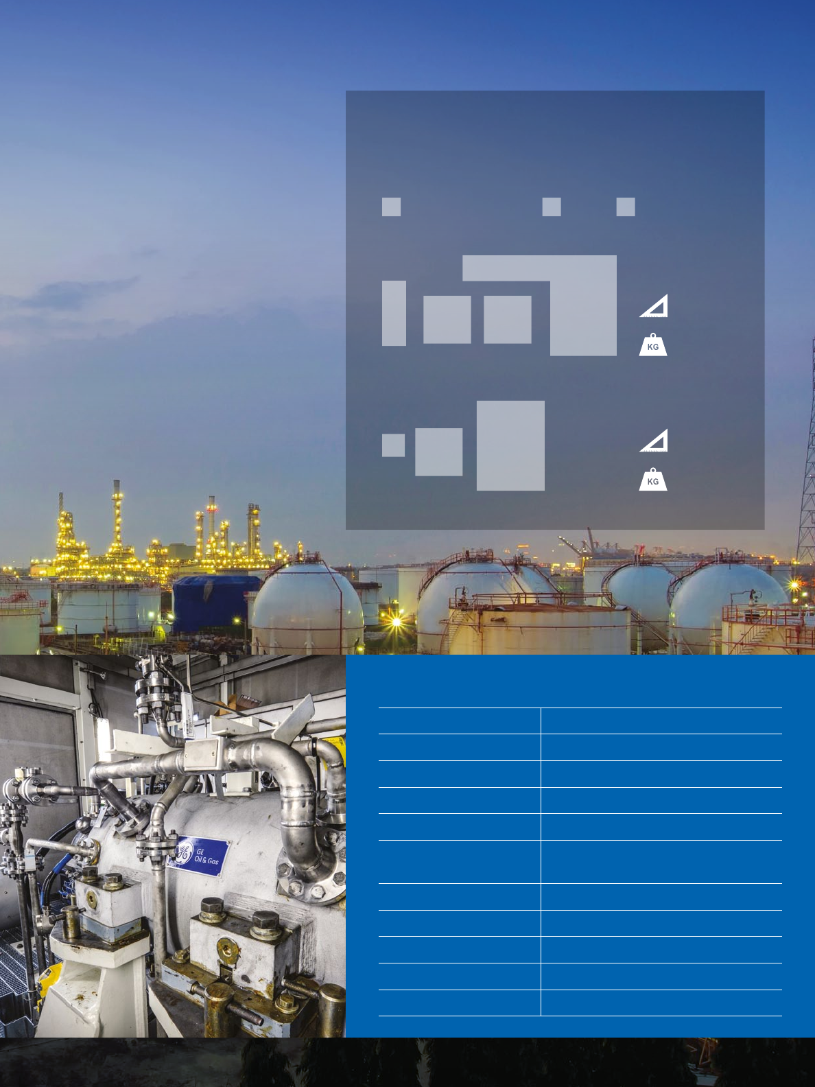
93,000 kg
(205,000 lb)
67,000 kg
(148,000 lb)
85 m2
(915 ft2)
39 m2
(420 ft2)
Traditional configuration
Highly compact
HPRC has up to 50% smaller footprint and 30% lighter weight
than traditional train configurations.
HPRC
C
GA
C C
GA
Compressor Casings AUX GearboxGAC
Wide operating range in all applications
HPRC is well suited to a wide range of applications. The new
technology is best suited to gas with low-to-medium molecular
weight, where head per stage is a limiting factor – and the
greatest benefits can be realized in natural gas, petrochemical
and LNG.
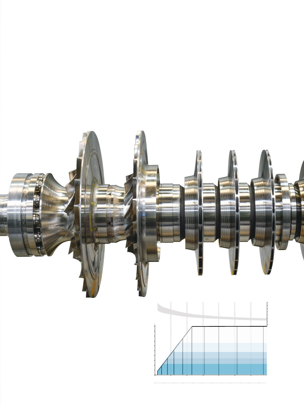
Optimized design
The use of both unshrouded and shrouded
impellers on a stacked rotor with hirth
teeth allows high tip speed and eliminates
the shrink-fit limitation typical of other
centrifugal compressors. Head per stage
has been increased and the number of
stages reduced by about 50%. The result
is a higher total pressure ratio with fewer
impellers.
Fewer stages allows rotating speed to
be increased with sound rotordynamics,
which in turn increases flow coefficient
of the stages and provides a high
compression efficiency.
The parallel shaft gear can be replaced
by an epicyclical gear for higher speed
requirements. It has a higher ratio
and significantly lower losses than an
equivalent parallel shaft gear. With co-axial
input and output shaft lines, the epicyclical
has no need for shaft offsets between
driver and driven machinery – so it is also
a much more compact and lightweight
solution.
Combining multiple bodies into one
increases the number of inlet and outlet
flanges.
Vol Flow
(Am3/h)
100
90
80
70
60
50
40
30
20
10
0
P. RATIO
RPM
35,000
30,000
25,000
20,000
15,000
10,000
5,000
0
0 5 10 15 20
0 10,000 20,000 30,000 40,000 50,000 60,000 70,000
25 30 35 40 45 50 55
(MMSCFD)
30
25
21
16
35
mol. w.
800
700
600
500
450
400
350
300
250
Machine Size

GE_HPRC_brochure-021315
GE Oil & Gas
Global Headquarters
The Ark
201 Talgarth Road, Hammersmith
London, W6 8BJ, UK
T +44 207 302 6000
customer.service.center@ge.com
Turbomachinery Solutions
Via Felice Matteucci, 2
50127 Florence, Italy
T +39 055 423 211
F +39 055 423 2800
customer.service.center@ge.com
Nuovo Pignone S.p.A.
Nuovo Pignone S.r.l.
For complete contact information,
please refer to our website.
geoilandgas.com/HPRC
The information contained herein is general in nature and is not
intended for specific construction, installation or application
purposes. GE reserves the right to make changes in specifications
or add improvements at any time without notice or obligation.
GE, the GE Monogram, and imagination at work are registered
trademarks of the General Electric Company.
©2015 General Electric Company
All Rights Reserved
