GemTek Technology AD920429 Wireless ADSL Router User Manual WX 5801 Quick Installation Guide
Gemtek Technology Co., Ltd. Wireless ADSL Router WX 5801 Quick Installation Guide
UserManual.wiki
>
GemTek Technology
>
AD920429 User Manual
>
Users Manual
Contents
1.
DoC Statement
2.
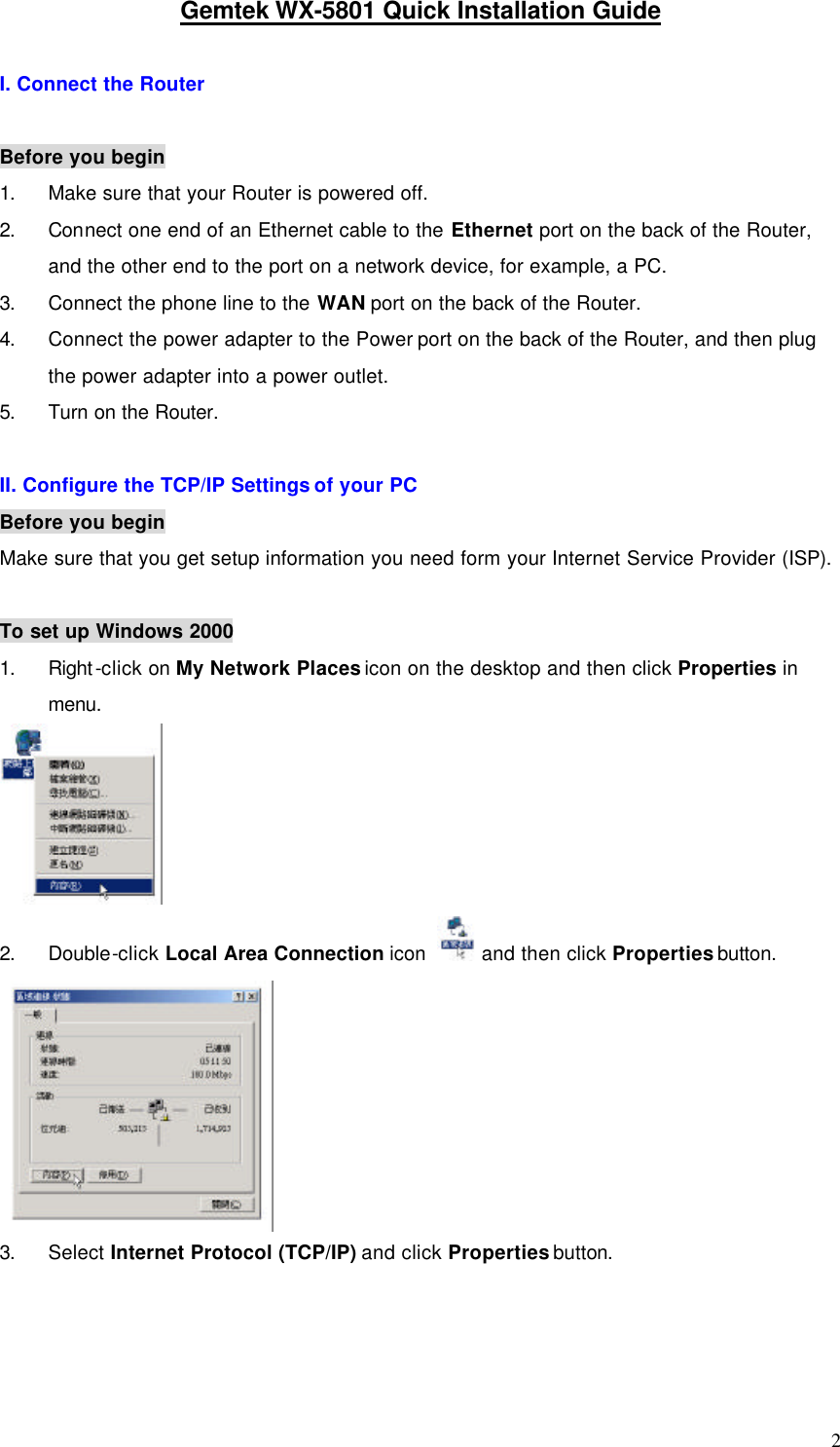
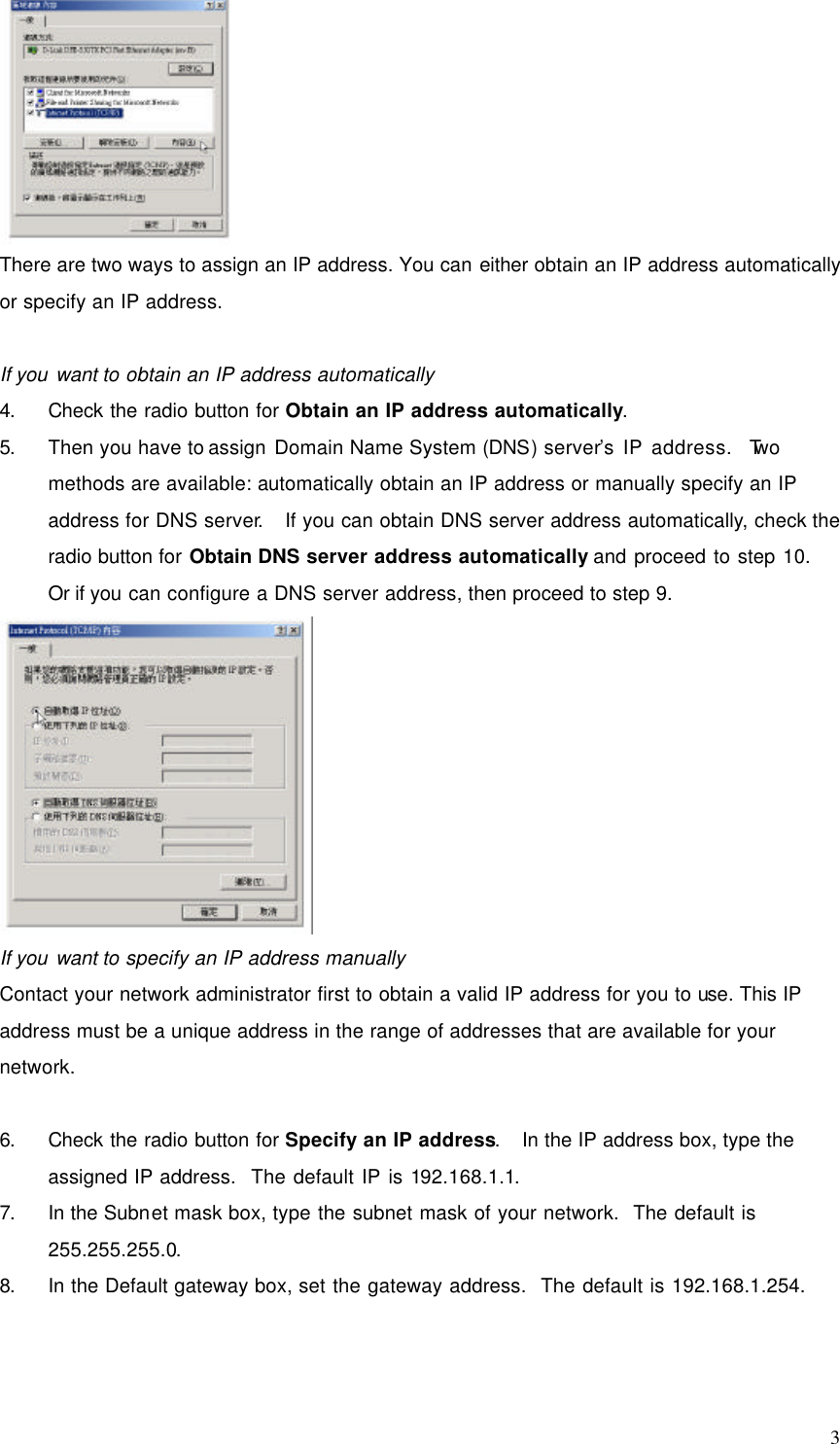
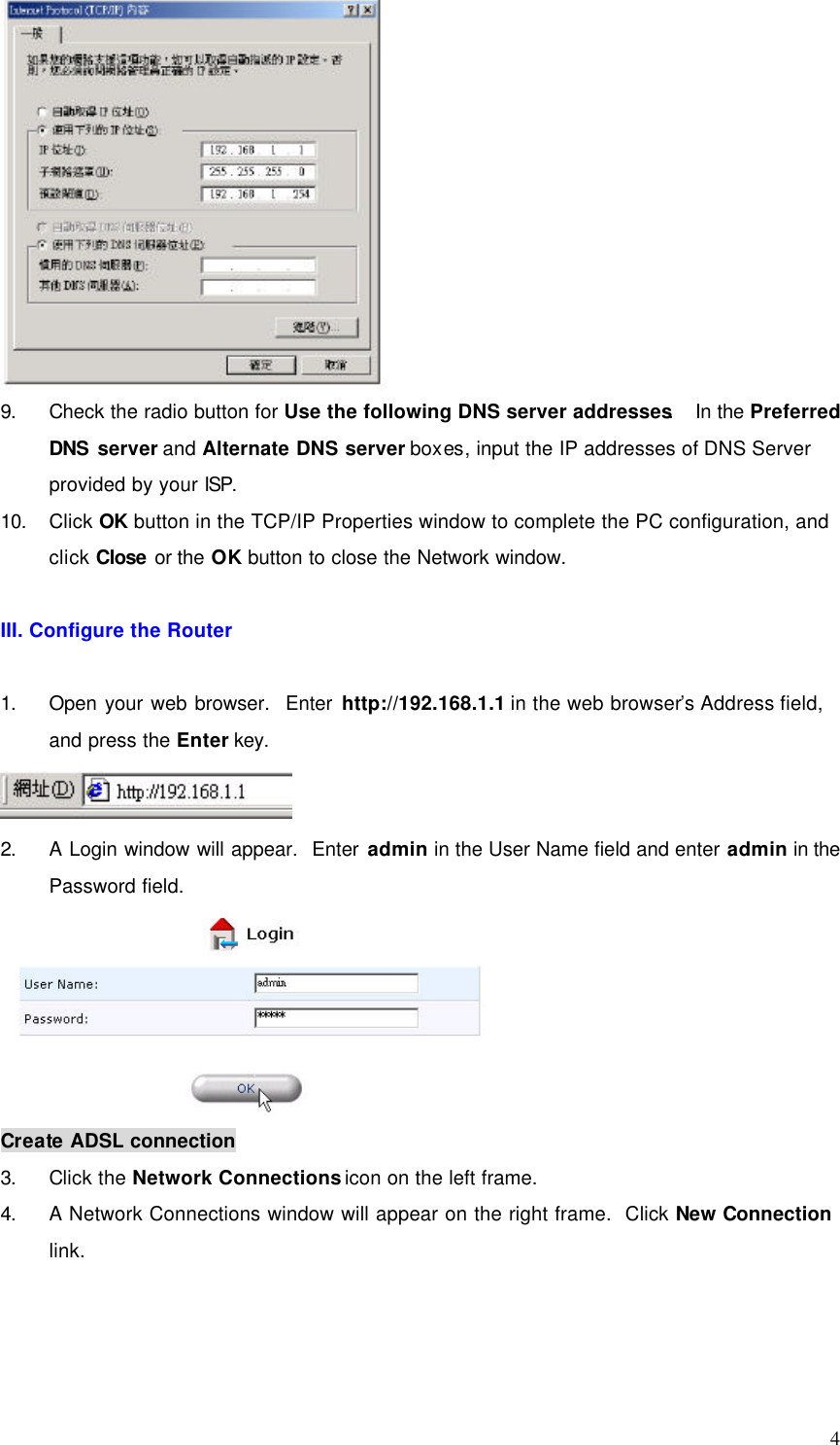
Users Manual
Users Manual
Navigation menu
Upload a User Manual
Namespaces
Wiki Guide
HTML
PDF
Info
Views
User Manual
Discussion / Help
Navigation