GemTek Technology AD920429 Wireless ADSL Router User Manual WX 5801 Quick Installation Guide
Gemtek Technology Co., Ltd. Wireless ADSL Router WX 5801 Quick Installation Guide
Contents
- 1. DoC Statement
- 2. Users Manual
Users Manual
Wireless ADSL Router
WX-5801
Quick Installation Guide
Version 1.0 – May 20, 2003
Gemtek Technology Co., Ltd.
2
Gemtek WX-5801 Quick Installation Guide
I. Connect the Router
Before you begin
1. Make sure that your Router is powered off.
2. Connect one end of an Ethernet cable to the Ethernet port on the back of the Router,
and the other end to the port on a network device, for example, a PC.
3. Connect the phone line to the WAN port on the back of the Router.
4. Connect the power adapter to the Power port on the back of the Router, and then plug
the power adapter into a power outlet.
5. Turn on the Router.
II. Configure the TCP/IP Settings of your PC
Before you begin
Make sure that you get setup information you need form your Internet Service Provider (ISP).
To set up Windows 2000
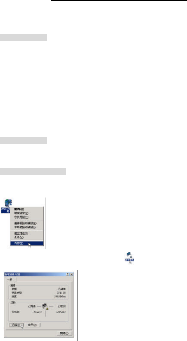
1. Right-click on My Network Places icon on the desktop and then click Properties in
menu.
2. Double-click Local Area Connection icon and then click Properties button.
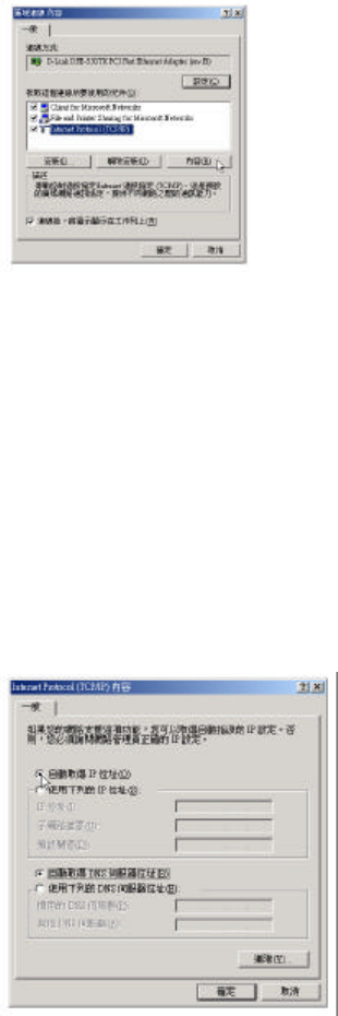
3. Select Internet Protocol (TCP/IP) and click Properties button.
3
There are two ways to assign an IP address. You can either obtain an IP address automatically
or specify an IP address.
If you want to obtain an IP address automatically
4. Check the radio button for Obtain an IP address automatically.
5. Then you have to assign Domain Name System (DNS) server’s IP address. Two
methods are available: automatically obtain an IP address or manually specify an IP
address for DNS server. If you can obtain DNS server address automatically, check the
radio button for Obtain DNS server address automatically and proceed to step 10.
Or if you can configure a DNS server address, then proceed to step 9.
If you want to specify an IP address manually
Contact your network administrator first to obtain a valid IP address for you to use. This IP
address must be a unique address in the range of addresses that are available for your
network.
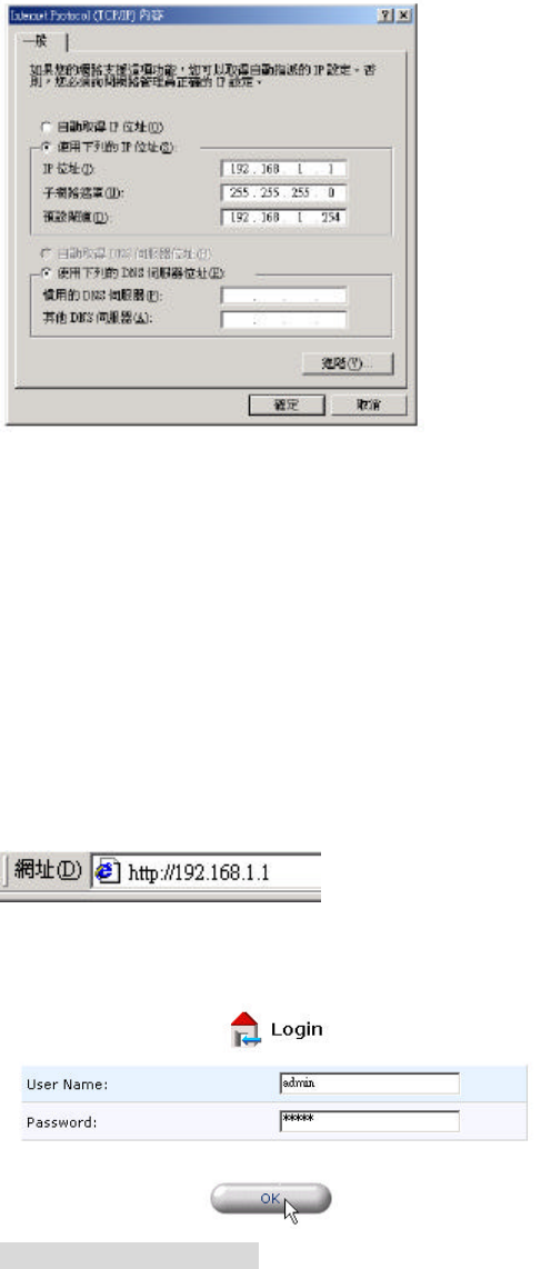
6. Check the radio button for Specify an IP address. In the IP address box, type the
assigned IP address. The default IP is 192.168.1.1.
7. In the Subnet mask box, type the subnet mask of your network. The default is
255.255.255.0.
8. In the Default gateway box, set the gateway address. The default is 192.168.1.254.
4
9. Check the radio button for Use the following DNS server addresses. In the Preferred
DNS server and Alternate DNS server boxes, input the IP addresses of DNS Server
provided by your ISP.
10. Click OK button in the TCP/IP Properties window to complete the PC configuration, and
click Close or the OK button to close the Network window.
III. Configure the Router
1. Open your web browser. Enter http://192.168.1.1 in the web browser’s Address field,
and press the Enter key.
2. A Login window will appear. Enter admin in the User Name field and enter admin in the
Password field.
Create ADSL connection
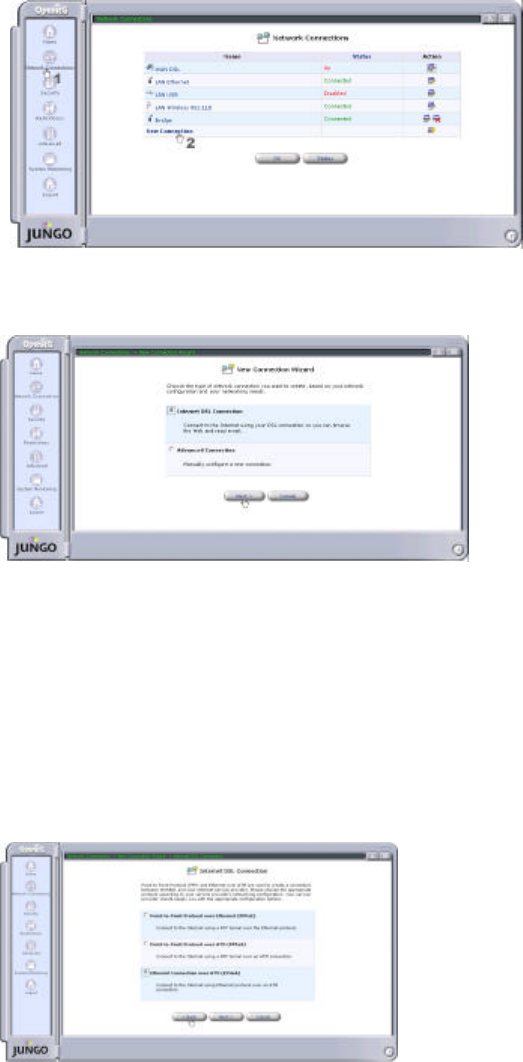
3. Click the Network Connections icon on the left frame.
4. A Network Connections window will appear on the right frame. Click New Connection
link.
5
5. A Network Connection Wizard page will appear. Check radio button for Internet DSL
Connection, and then click Next button to continue.
6. Choose the appropriate protocol according to your ISP's networking configuration. Your
ISP should provide you the appropriate configuration options. There are three
configuration options: Point-to-Point Protocol over Ethernet (PPPoE), Point-to-Point
Protocol over ATM (PPPoA), and Ethernet Connection over ATM (ETHoA).
The examples here use ETHoA option.
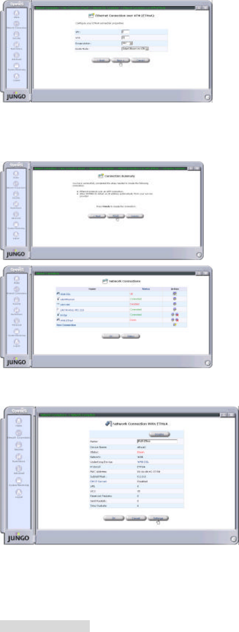
7. Select ETHoA radio button and click Next button to continue.
8. Enter/Select the values required by your ISP to configure the ETHoA connection. For
example:
VPI : 0
VCI: 35
Encapsulation: LLC
Route Mode: Bridged Ethernet over ATM
9. Click Next button to continue.
6
10. The Connection Summary window will appear. Click Finish button to create a new
connection. You will see in the Network Connections window a new connection WAN
ETHoA has been added.
11. Click WAN ETHoA link and a Configure WAN ETHoA page will appear. Click Settings
button for further setting.
12. A Configure WAN ETHoA window will appear. The Default setting is DHCP Client
enable, if you use the fixed IP, you must fill the IP setting provided by your ISP. Click OK
button to save your setup settings.
Check ADSL Status
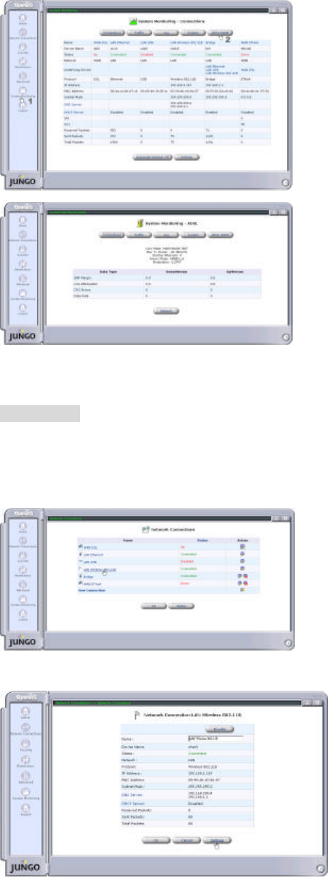
1. Click System Monitoring icon on the left frame, and a System Monitoring – Connections
page will appear on the right frame.
7
2. Click ADSL PARM button on the top right and a System Monitoring – Connections page
will show up for you to see the ADSL Status.
LAN Setting
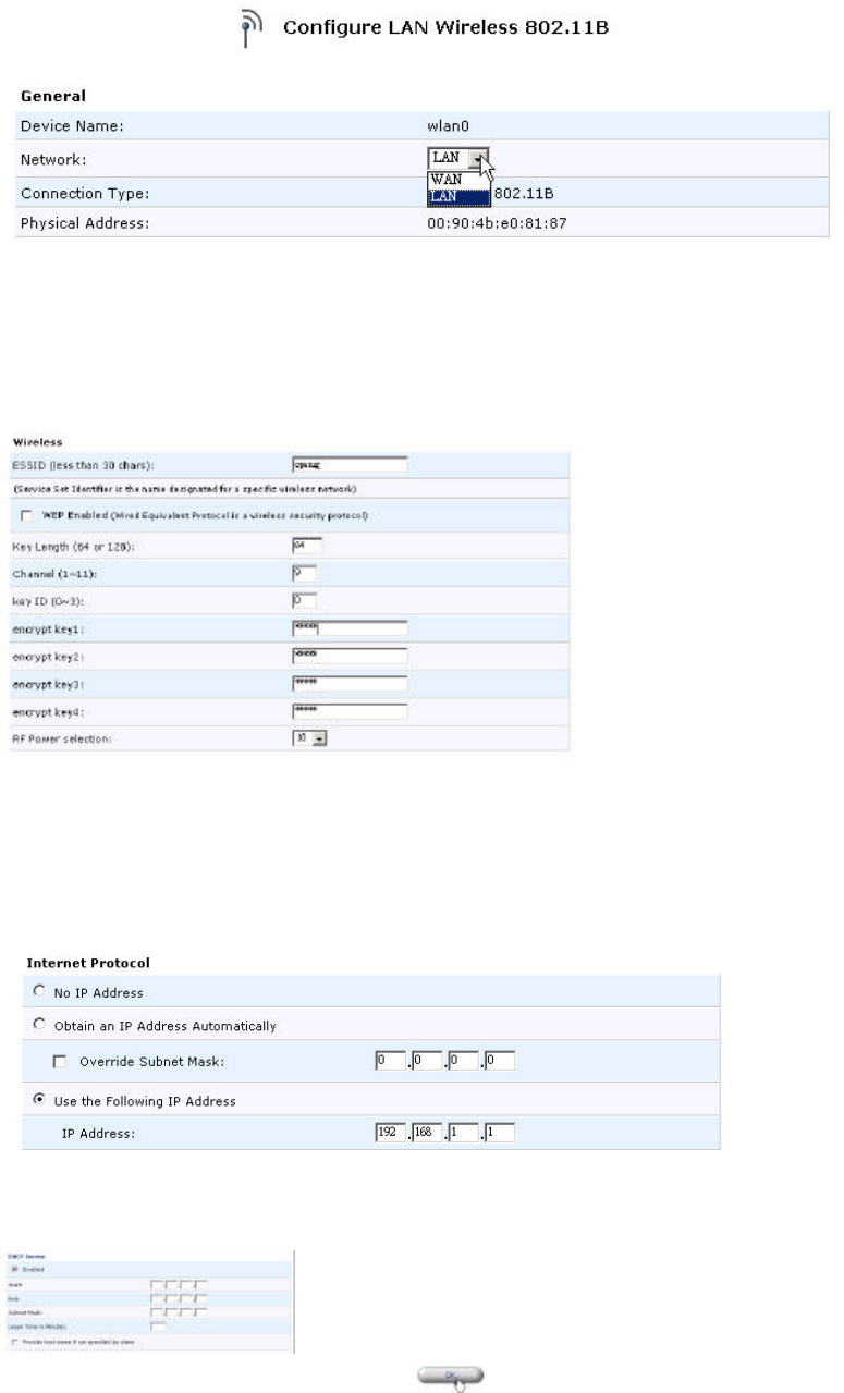
1. Click the Network Connections icon on the left frame.
2. Click LAN Wireless 802.11B link to enter Network Connection LAN Wireless 802.11B
page.
3. Click Settings button.
4. In General box, select your Network. The LAN Bridge includes Ethernet, Wireless and
8
USB interface.
5. In Wireless box, type the ESSID (the default is openrg). Then configure the WEP
(Wired Equivalent Protocol). The default of Wireless WEP is Disable. If you want to
enable WEP, check the box for WEP Enabled, and set the following items: Key Length
(the default is 64), Channel (the default is 9), Key ID, and RF Power selection.
6. In Internet Protocol box, three methods are available for you to configure the IP address:
No IP Address, Obtain an IP Address Automatically, and Use the Following IP Address.
The default is User the Following IP Address (the radio button for User the Following IP
Address is checked) and the default IP Address is 192.168.1.1.
7. In DHCP Server box, the default setting is Enable. Check the box for Enable and
configure the following items: Start and End IP, Subnet Mask, and Lease Time in Minutes.
8. Click OK button to save your settings.
9
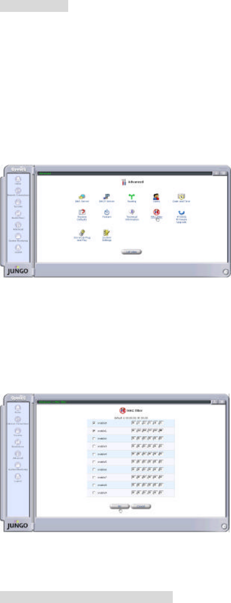
Set MAC Filter
This feature filters specific MAC addresses within the wireless local area network (WLAN) from
accessing the network. The default MAC filter setting is Disable. If you enable the MAC
filter, only the MAC Addresses on the list grant to access the network, and the other wireless
Client MACs will be filtered by WX5801 and DENY to access anywhere.
1. Click Advanced icon on the left frame, and an Advanced setting page will appear on the
right frame.
2. Click MAC filter icon, and it will bring up a MAC filter setting table.
3. Check the enable box, and fill in the MAC address of the wireless clients you allow to
access the network. For example, check enable0 and enable1 boxes and type
00:11:22:33:44:55 and 00:AA:BB:CC:DD:EE. On this example, only the MAC
“00:11:22:33:44:55” and “00:AA:BB:CC:DD:EE” grant to access to WX5801. The other
wireless client MAC will be DENIED to access.
4. Click OK button to save your settings.
Configuration File Download/Upload
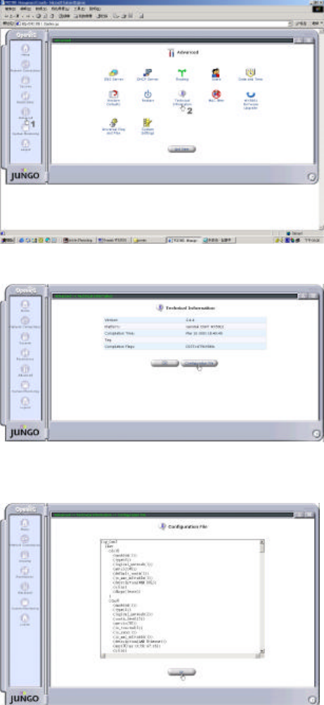
1. Click Advanced icon on the left frame, and an Advanced setting page will appear on the
right frame.
10
2. Click Technical Information icon, and a Technical Information page will appear.
3. Click Configuration File button, and a Configuration File will appear.
4. In the bottom of the page, you can click Upload/Download Configuration File button to
upload/download configuration file.
11
Federal Communication Commission Interference Statement
This equipment has been tested and found to comply with the limits for a Class
B digital device, pursuant to Part 15 of the FCC Rules. These limits are
designed to provide reasonable protection against harmful interference in a
residential installation. This equipment generates, uses and can radiate radio
frequency energy and, if not installed and used in accordance with the
instructions, may cause harmful interference to radio communications.
However, there is no guarantee that interference will not occur in a particular
installation. If this equipment does cause harmful interference to radio or
television reception, which can be determined by turning the equipment off and
on, the user is encouraged to try to correct the interference by one of the
following measures:
- Reorient or relocate the receiving antenna.
- Increase the separation between the equipment and receiver.
- Connect the equipment into an outlet on a circuit different from that to which
the receiver is connected.
- Consult the dealer or an experienced radio/TV technician for help.
FCC Caution: To assure continued compliance, any changes or modifications
not expressly approved by the party responsible for compliance could void
the user's authority to operate this equipment.
This device complies with Part 15 of the FCC Rules. Operation is subject to the
following two conditions: (1) This device may not cause harmful interference,
and (2) this device must accept any interference received, including
interference that may cause undesired operation.
IMPORTANT NOTE:
FCC Radiation Exposure Statement:
This equipment complies with FCC radiation exposure limits set forth for an
uncontrolled environment. This equipment should be installed and operated
with minimum distance 20cm between the radiator & your body.
This transmitter must not be co-located or operating in conjunction with any
other antenna or transmitter.