GemTek Technology ADV980114G DDR2201 v1 ADSL2+ Residential Gateway User Manual Manual 2
Gemtek Technology Co., Ltd. DDR2201 v1 ADSL2+ Residential Gateway Manual 2
Contents
- 1. Manual 1
- 2. Manual 2
- 3. Manual 3
Manual 2
Http Server Port
4030765 Rev 01 57
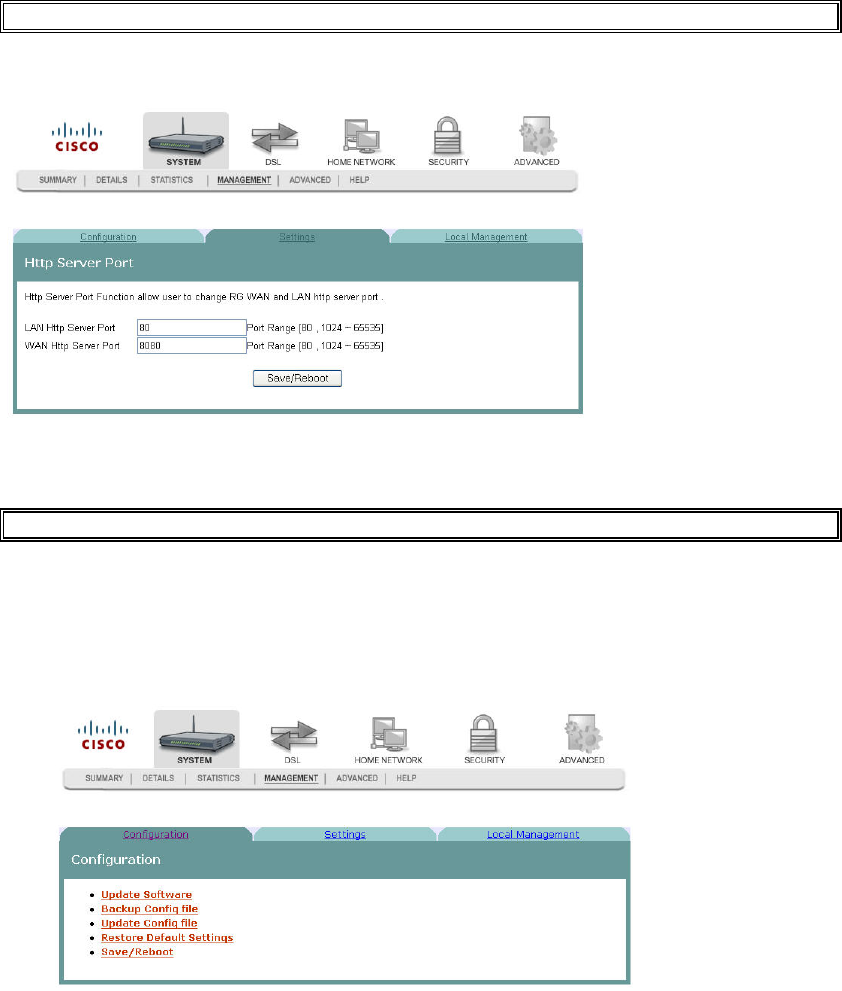
Http Server Port
The Http Server Port screen allows you to modify the
Q. to reviewers
Modifying the Http Server Ports
Q. to reviewers: need help with procedure
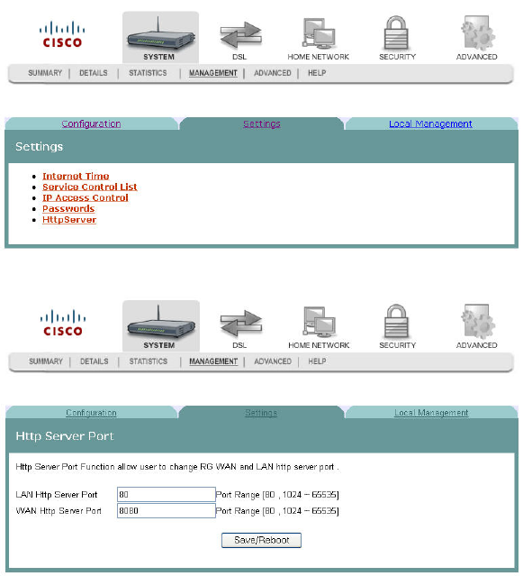
To modify the Http Server ports, complete the following steps.
1Click System on the main screen.
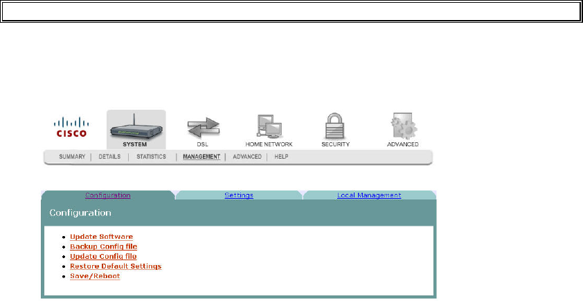
2Click Management. The Configuration screen opens with the Configuration tab
in the forefront.
3-6-2009 Draft
Cha
p
te
r
3 Confi
g
uration and O
p
eration
58 4030765 Rev 01
3Click the Settings tab. The Settings screen opens.
4Click HttpServer. The Http Server Port opens.
5In the LAN Http Server Port field, enter the
6In WAN Http Server Port field, enter the
3-6-2009 Draft
System Log Configuration
4030765 Rev 01 59
System Log Configuration
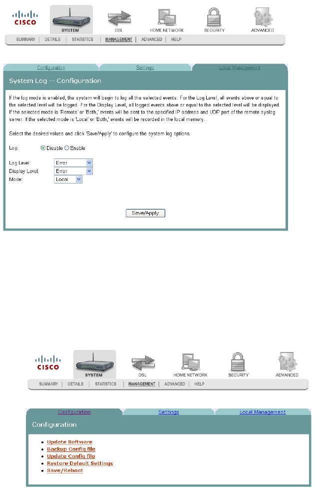
The System Log -- Configuration screen allows you to log all the selected events on
the residential gateway. For example, a failed login is an event that you can select.
Path: System > Management > Local Management > System Log Configuration
Logging Events
To log selected events, complete the following steps.
1Click System on the main screen.
2Click Management. The Configuration screen opens with the Configuration tab
in the forefront.
3-6-2009 Draft
Cha
p
te
r
3 Confi
g
uration and O
p
eration
60 4030765 Rev 01
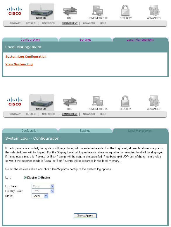
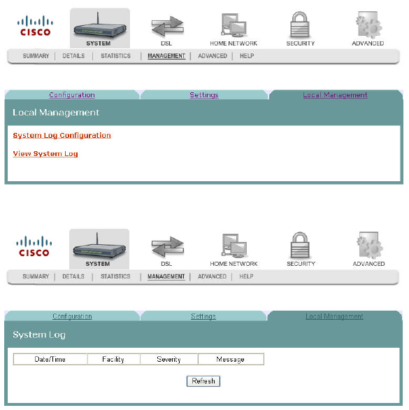
3Click the Local Management tab. The Local Management screen opens.
4Click System Log Configuration. The System Log Configuration screen opens.
5Do you want to enable the logging of events?
If yes, in the Log field select Enable and go to step 6.
If no, in the Log field, select Disable and click Save/Apply to turn off
logging. You have completed this procedure.
6In the Log Level field, select the level of events that you want to log from the
following options. All events above or equal to the selected level will be logged.
Emergency
Alert
Critical
Error
Warning
Notice
Informational
3-6-2009 Draft
System Log Configuration
4030765 Rev 01 61
Debugging
7In the Display Level field, select the level of the logged events that you want to
display from the following options. All logged events above or equal to the
selected level will be displayed.
Emergency
Alert
Critical
Error
Warning
Notice
Informational
Debugging
8Select the mode for the logging from the following options. If the selected mode
is "remote" or "both," events are sent to the specified IP address and UDP port of
the remote syslog server. If the selected mode is "local" or "both," events are
recorded in the local memory.
Local. Events are logged in memory. You must log in to the device to display
the events.
Remote. Events log is sent to a remote server (syslog server).
Both. Events are logged in memory and are sent to the remote server.
9Click Save/Apply to start logging events.
Disabling Logging
To disable the logging function, complete the following steps.
Q. to reviewer test this procedure against application
1Click System on the main screen.
2Click Management. The Configuration screen opens with the Configuration tab
in the forefront.
3-6-2009 Draft

Cha
p
te
r
3 Confi
g
uration and O
p
eration
62 4030765 Rev 01
3Click the Local Management tab. The Local Management screen opens.
4Click System Log Configuration. The System Log Configuration screen opens.
5In the Log field, click Disable.
6In the Log Level field, select from the following options to indicate the level of
alarms to be logged:
Emergency
Alert
Optical
Error
Warning
Notice
Informational
Debugging
7In the Display Level field, select from the following options to indicate the level
of alarms that you want displayed:
3-6-2009 Draft
System Log Configuration
4030765 Rev 01 63
Emergency
Alert
Optical
Error
Warning
Notice
Informational
Debugging
8In the Mode field, select from the following options to indicate the location to
store the logs.
Local. Store on the residential gateway.
Remote. Store on a remote log server.
Both. Store on the residential gateway and on the remote log server.
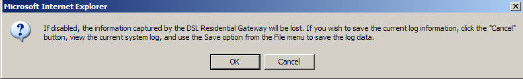
9Click Save/Apply. The following prompt appears alerting you that you will lose
any information captured by the residential gateway:
10 Are you sure you want to disable logging and lose the captured data?
If yes, click OK to turn off logging.
If no, click Cancel.
3-6-2009 Draft
Cha
p
te
r
3 Confi
g
uration and O
p
eration
64 4030765 Rev 01
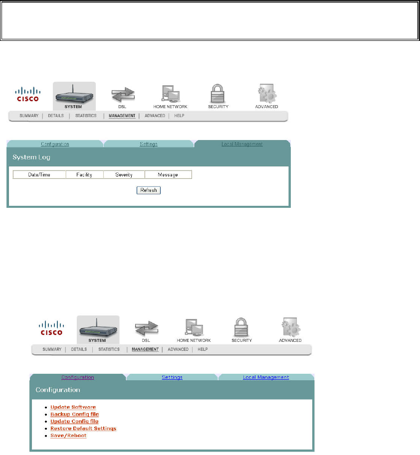
System Logs
The System Log screen allows you to view the logs of activity for the residential
gateway.
Q. to reviewers. How many or how big are events stored? How long are
they stored? Will reset or power failure clear t hem? If this is a circular
file, if so max size before roll over.
Path: System > Management > Local Management > View System Log
Viewing System Logs
To view the system log for the residential gateway, complete the following steps.
1Click System on the main screen.
2Click Management. The Configuration screen opens with the Configuration tab
in the forefront.
3-6-2009 Draft
System Logs
4030765 Rev 01 65
3Click the Local Management tab. The Local Management screen opens.
4Click View System Log. The System Log screen opens.
5Review the log entries on the screen.
6Click Refresh to refresh the system log.
3-6-2009 Draft
Cha
p
te
r
3 Confi
g
uration and O
p
eration
66 4030765 Rev 01
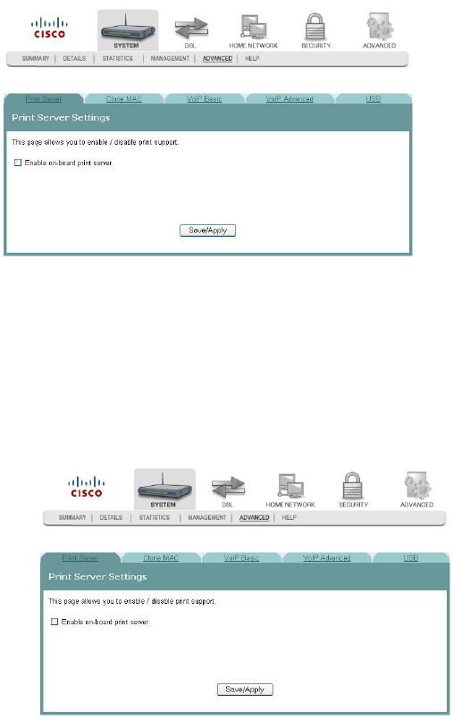
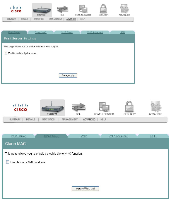
Print Server Settings
The Print Server Setting screen allows you to enable or disable printer support from
the USB connection.
Path: System > Advanced > Print Server
Enabling the Print Server
To enable the print server, complete the following steps.
1Click System on the main screen.
2Click the Advanced tab. The Print Server settings screen opens with the Print
Server tab in the forefront.
3-6-2009 Draft
Print Server Settings
4030765 Rev 01 67
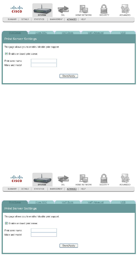
3Select the Enable on-board print server check box. The screen populates with
more fields.
4In the Print server name field, enter the name of the print server you want to
enable.
5In the Make and model field, enter the make and model of the printer.
6Click Save/Apply to enable the print server.
Disabling the Print Server
To disable the print server, complete the following steps.
1Click System on the main screen.
2Click the Advanced tab. The Print Server settings screen opens with the Print
Server tab in the forefront.
3-6-2009 Draft
Cha
p
te
r
3 Confi
g
uration and O
p
eration
68 4030765 Rev 01
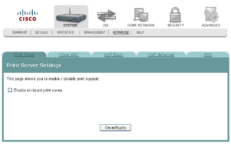
3Clear the Enable on-board print server check box. The screen refreshes and the
fields for entering print server name, make, and mode are removed from the
screen.
4Click Save/Apply to disable the print server.
3-6-2009 Draft
Clone MAC Addresses
4030765 Rev 01 69
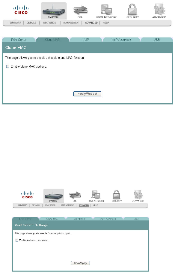
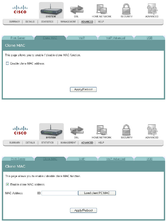
Clone MAC Addresses
The Clone MAC screen allows you to enable or disable the clone MAC function. The
Clone MAC function allows you to clone MAC addresses so that the residential
gateway assumes the MAC address of an attached device or a user-specified MAC
address.
Path: System > Advanced > Clone MAC
Enabling the Clone MAC Function
To enable the Clone MAC function, complete the following steps.
1Click System on the main screen.
2Click the Advanced tab. The Print Server settings screen opens with the Print
Server tab in the forefront.
3-6-2009 Draft
Cha
p
te
r
3 Confi
g
uration and O
p
eration
70 4030765 Rev 01
3Click the Clone MAC tab.
4Select the Enable clone MAC address check box. The screen populates with
more fields.
5In the MAC Address field, enter the MAC address that you want to clone. You
can also click Load/client PC MAC to locate an address you want to clone.
6Click Apply/Reboot to clone the MAC address. The residential gateway reboots
and assumes the MAC address you have specified.
Disabling the Clone MAC Function
To disable the Clone MAC function, complete the following steps.
1Click System on the main screen.
3-6-2009 Draft
Clone MAC Addresses
4030765 Rev 01 71
2Click the Advanced tab. The Print Server settings screen opens with the Print
Server tab in the forefront.
3Click the Clone MAC tab.
4Uncheck the Enable clone MAC address check box. The screen refreshes and the
field for entering the MAC address is removed from the screen.
5Click Apply/Reboot to disable the Clone MAC function.
3-6-2009 Draft
Cha
p
te
r
3 Confi
g
uration and O
p
eration
72 4030765 Rev 01
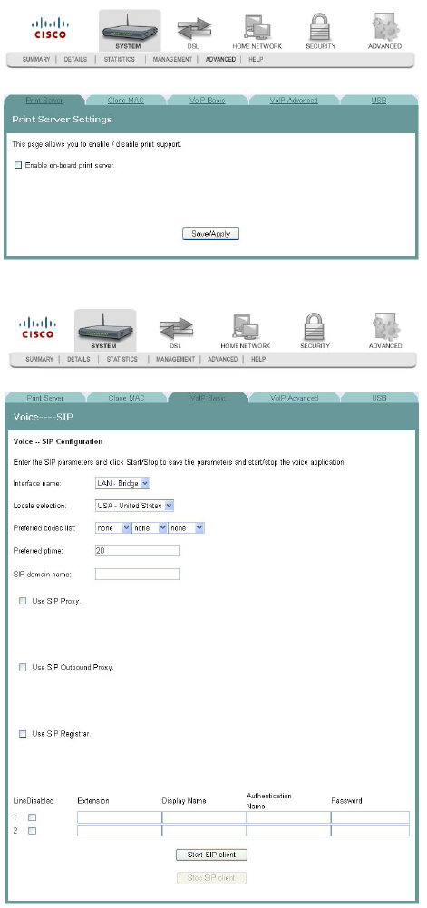
Voice SIP Basic Configuration
The Voice ---- SIP screen allows you to enter and save the session initiation protocol
(SIP) parameters and to start and stop the voice application.
Path: System > Advanced > VoIP Basic
Setting Up VoIP
To enter the VoIP parameters, complete the following steps.
1Click System on the main screen.
3-6-2009 Draft
Voice SIP Basic Configuration
4030765 Rev 01 73
2Click Advanced. The Print Server Settings screen opens with the Print Server tab
in the forefront.
3Click the VoIP Basic tab. The Voice ---- SIP screen opens.
4In the Interface name field, select the interface you want to use for VoIP.
5In the Locale selection field, select the country where you are located.
6In the Preferred codec field, select one of the following codec values:
Note: If you want to indicate an order of preference, enter a codec value for each
column.
G711U
3-6-2009 Draft
Cha
p
te
r
3 Confi
g
uration and O
p
eration
74 4030765 Rev 01
G711A
G723
G726
G729
BV16
iLBC
7In the Preferred ptime field, enter the time in seconds.
8In the SIP domain name field, enter the domain name for the session initiation
protocol (SIP) server.
9Do you wish to use SIP Proxy?
If yes, click in the Use SIP Proxy field to enter a check mark.
If no, make sure the Use SIP Proxy field is deselected.
3-6-2009 Draft
Voice SIP Basic Configuration
4030765 Rev 01 75
10 Do you wish to use an SIP Outbound proxy?
If yes, select the Use SIP Outbound Proxy field.
If no, make sure the Use SIP Outbound Proxy field is deselected.
11 Do you wish to use SIP Registrar?
If yes, select the Use SIP Registrar field.
If no, make sure the Use SIP Registrar field is deselected.
12 Do you wish to enable SIP tag matching?
If yes, select the Enable SIP tag matching (clear for Vonage Interop) field.
If no, make sure the Enable SIP tag matching (clear for Vonage Interop) field
is deselected.
13 Do you wish to use a remote server for SIP log messages?
If yes, select the Remote server for SIP log messages field.
If no, make sure the Remote server for SIP log messages field is deselected.
14 In the Log IP Address field, enter the IP address for the log server.
15 In the Log port field, enter the port number for the log server.
16 In the Extension field, enter the phone number (extension) for the VoIP line.
17 In the Password field, enter the password for the extension. This allows you to
authenticate the phone number.
18 Do you want to activate the line?
If yes, click Start SIP client to save your settings and to activate the line.
If no, click Stop SIP client to deactivate the line.
3-6-2009 Draft
Cha
p
te
r
3 Confi
g
uration and O
p
eration
76 4030765 Rev 01
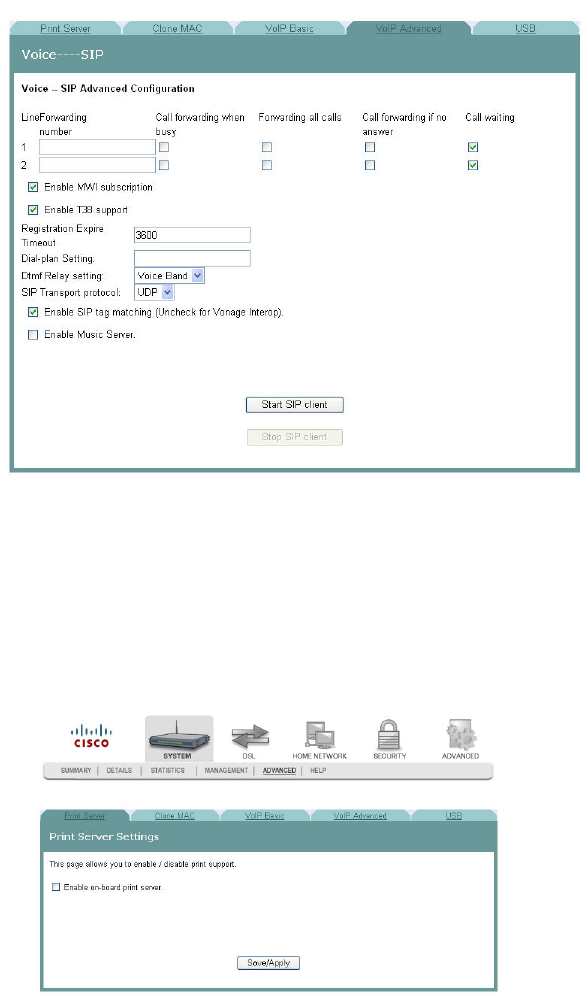
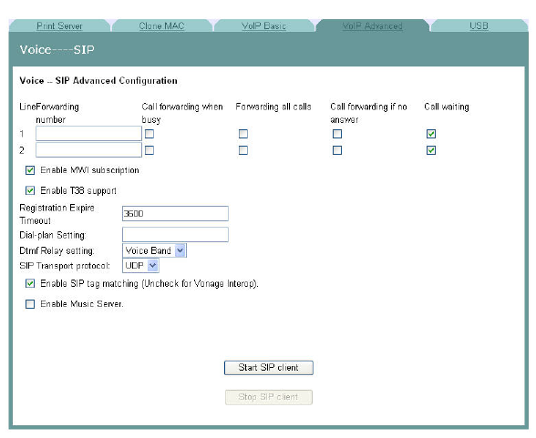
Voice SIP Advanced Configuration
The Voice----SIP screen allows you to configure the more advanced VOIP features,
such as call forwarding and ....
Path: System > Advanced > VoIP Advanced
Setting Up Advanced VOIP Features
To set up the advanced VOIP features, complete the following steps.
1Click System on the main screen.
2Click Advanced. The Print Server Settings screen opens with the Print Server tab
in the forefront.
3-6-2009 Draft
Voice SIP Advanced Configuration
4030765 Rev 01 77
3Click the VoIP Advanced tab. The Voice ---- SIP screen opens.
4In the Forwarding Line number field, enter the number to which you want to
forward calls. Configure how calls are forwarded to this line using the following
options:
aCheck the Call forwarding when busy check box if you want to forward this
line to another number when this line is busy.
bCheck the Forwarding all calls check box if you want to forward all calls to
this line.
cCheck the Call forwarding if no answer check box if you want to forward this
line if the caller receives no answer.
dCheck the Call waiting check box if you want to enable call waiting for this
line.
5Repeat step 4 for a second phone line for which you wish to forward incoming
calls.
6Check the Enable MWI subscription check box if you want to enable message
waiting indicator.
7Check the Enable T38 support check box if you want to enable T38 fax support.
8In the Registration Expire Timeout field, enter the registration expiration time of
the SIP client.
9In the Dial-Plan Setting field, enter the dial plan for the line. For example, enter
how many digits the user must enter before the call attempt is made.
10 In the Dtmf Relay setting field, select one of the following settings:
Sip Info
RFC2833
Voice Band
3-6-2009 Draft
Cha
p
te
r
3 Confi
g
uration and O
p
eration
78 4030765 Rev 01
11 In the SIP Transport protocol field, select the protocol you will support from the
following options:
All
TCP
UDP
TLS
12 Check the Enable SIP tag matching (Uncheck for Vonage Interop) check box if
you want to enable session initiation protocol.
13 Check the Enable Music Server check box if you want to have music playing
while callers wait.
14 Click Start SIP client or click Stop SIP client if you want to start or stop the SIP
client.
3-6-2009 Draft
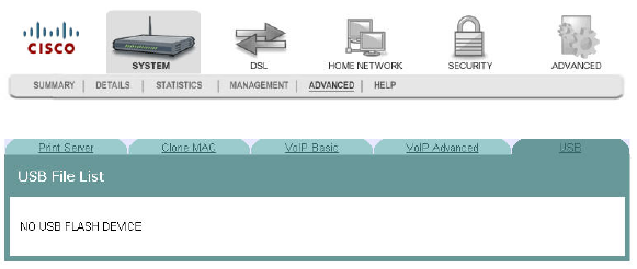
USB File List
4030765 Rev 01 79
USB File List
The USB File List screen allows you to view and download the content of a USB flash
drive from any computer connected to the gateway. This feature allows your
residential gateway to act like a shared network drive.
Path: System > Advanced > USB
3-6-2009 Draft
3-6-2009 Draft

4030765 Rev 01 81
The DSL tab allows you to check the status of the DSL connection and
to modify the configuration.
Use this chapter to help you check the status of the DSL connection,
such as performance, and to modify the DSL configuration.
4Chapter 4
DSL Configuration
In This Chapter
DSL Summary ....................................................................................... 82
DSL Statistics......................................................................................... 83
DSL Diagnostics.................................................................................... 85
DSL Settings........................................................................................... 87
ADSL Tone Settings.............................................................................. 89
DSL Advanced Settings ....................................................................... 91
3-6-2009 Draft
Cha
p
te
r
4 DSL Confi
g
uration
82 4030765 Rev 01
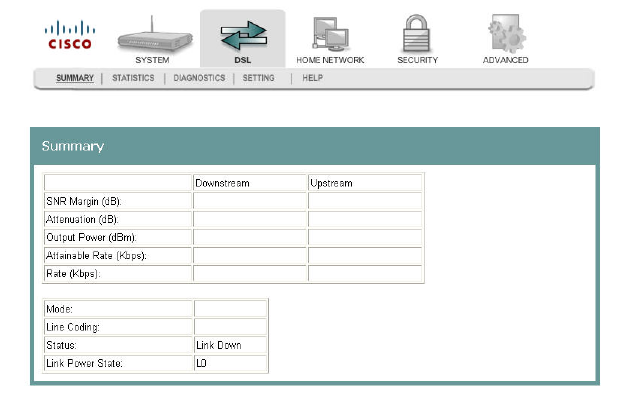
DSL Summary
The DSL Summary screen shows the DSL performance and operational
configuration of the DSL interface, such as signal to noise ratio and output power
and line coding. The DSL chip on the residential gateway automatically detects the
best method to use to communicate with the DSL access mutliplexer (DSLAM). This
screen reports the results of that process.
Path: DSL > Summary
3-6-2009 Draft
DSL Statistics
4030765 Rev 01 83
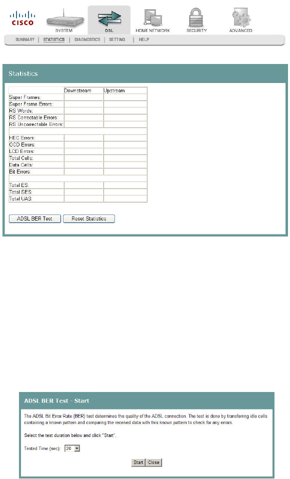
DSL Statistics
The DSL Statistics screen displays statistics for devices and interfaces on the ADSL
network. This screen shows the details of the physical layer of the DSL line such as
the connection rate and signal to noise ratio.
Path: DSL > Statistics
Testing the Quality of the DSL Connection
The ADSL Bit Error Rate (BER) test determines the quality of the ADSL connection.
The test is done by transferring idle cells containing a known pattern and comparing
the received data with this known pattern to check for any errors.
To test for quality of the DSL connection, complete the following steps.
1Click DSL on the main screen.
2Click the Statistics tab. The Statistics screen opens.
3Click ADSL BER Test. The ADSL BER Test - Start screen opens.
4In the Tested Time (sec) field, enter the duration of the test in seconds. Values
are: 1, 5, 10, 20, 60, 120, 180, or 240 seconds.
5Click Start on the ADSL BER Test - Start screen to start the test.
3-6-2009 Draft
Cha
p
te
r
4 DSL Confi
g
uration
84 4030765 Rev 01
Reset Statistics
To reset the statistics, complete the following steps.
1Click DSL on the main screen.
2Click the Statistics tab. The Statistics screen opens.
3Click Reset Statistics on the Statistics screen. This action clears the ADSL cell
counters and sets them to zero.
3-6-2009 Draft
DSL Diagnostics
4030765 Rev 01 85
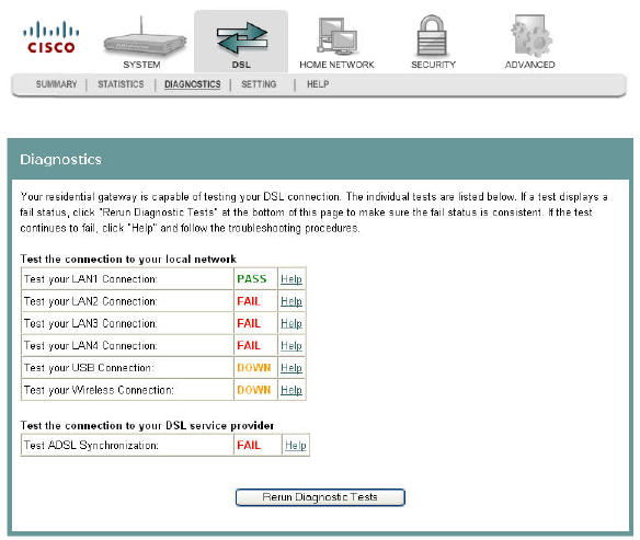
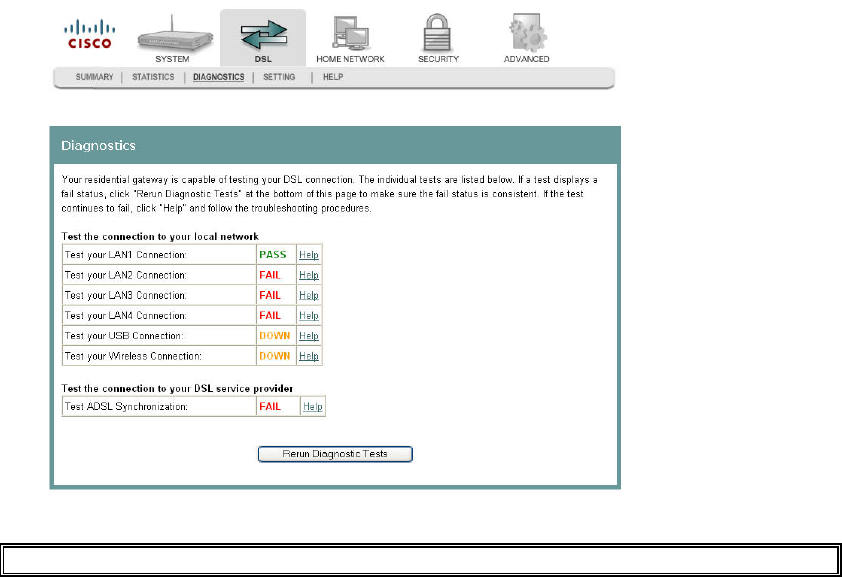
DSL Diagnostics
The Diagnostics screen shows the results of diagnostics tests that the residential
gateway performs while testing your DSL connection. The individual tests are listed
on the Diagnostics screen.
Path: DSL > Diagnostics
Running Diagnostic Tests
To run diagnostic tests for the residential gateway, complete the following steps.
1Click DSL on the main screen.
3-6-2009 Draft
Cha
p
te
r
4 DSL Confi
g
uration
86 4030765 Rev 01
2Click the Diagnostics tab. The Diagnostics screen opens.
3Click Run Diagnostics Tests to start the diagnostics test.
Q. to reviewers: How do they view the tests?
3-6-2009 Draft
DSL Settings
4030765 Rev 01 87
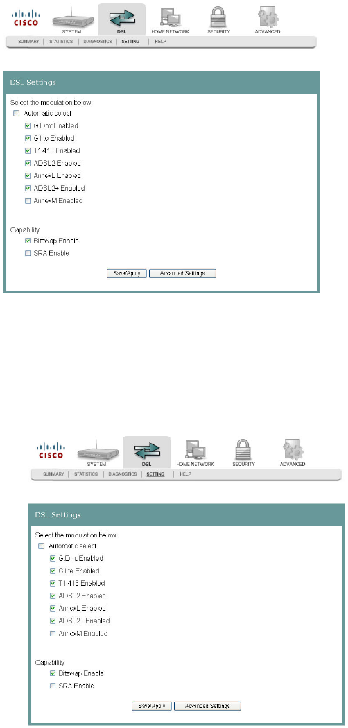
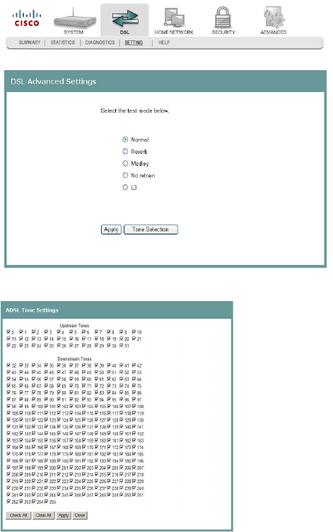
DSL Settings
The DSL Settings screen allows you to set the modulation for the residential
gateway, select a phone line pair, and to select advanced capability of the chip set:
seamless rate adaptation (SRA) and bitswap enable.
Path: DSL > Setting
Configuring DSL Settings
To configure the DSL settings for the residential gateway, complete the following
steps.
1Click DSL on the main screen. The Summary screen opens by default.
2Click the Setting tab. The DSL Settings screen opens.
3-6-2009 Draft
Cha
p
te
r
4 DSL Confi
g
uration
88 4030765 Rev 01
3Do you want to automatically select the modulation?
If yes, make sure the Automatic select check box is checked under Select the
modulation below field. Go to step 5.
If no, uncheck the Automatic Select check box. A list of modulation types
appears.
4Under the Select the modulation below area on the screen, select the modulation
that you want to use. You can select one or all of the following modulations:
G.Dmt Enabled
G.lite Enabled
T1.413 Enabled
ADSL2 Enabled
AnnexL Enabled
ADSL2+ Enabled
AnnexM Enabled
5Under the Capability field, select the capability that you want to use from the
following options:
Bitswap Enable
SRA Enable
6Click Save/Apply to save the configuration.
3-6-2009 Draft
ADSL Tone Settings
4030765 Rev 01 89
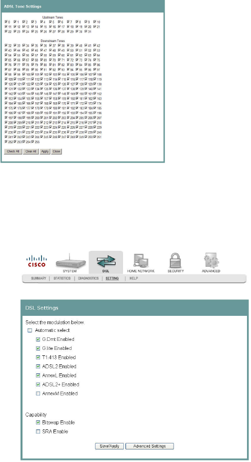
ADSL Tone Settings
The ADSL Tone Settings screen allows you to select active DSL tones or frequencies
used by the DSL transceiver.
Path: DSL > Setting > Advanced Settings > Tone Selection
Setting DSL Tones or Frequencies
To set DSL tones or frequencies, complete the following steps.
1Click DSL on the main screen. The Summary screen opens by default.
2Click the Setting tab. The DSL Settings screen opens.
3-6-2009 Draft
Cha
p
te
r
4 DSL Confi
g
uration
90 4030765 Rev 01
3Click Advanced Settings. The DSL Advanced Settings screen opens.
4Click Tone Selection. The ADSL Tone Settings screen opens.
5Select the ADSL tone settings as follows.
To select all the tones, click Check All.
To select individual tones, click Clear All and then select the tones you want.
6Click Apply to configure the tone settings.
7Click Close to return to the DSL Advanced Settings screen.
3-6-2009 Draft
DSL Advanced Settings
4030765 Rev 01 91
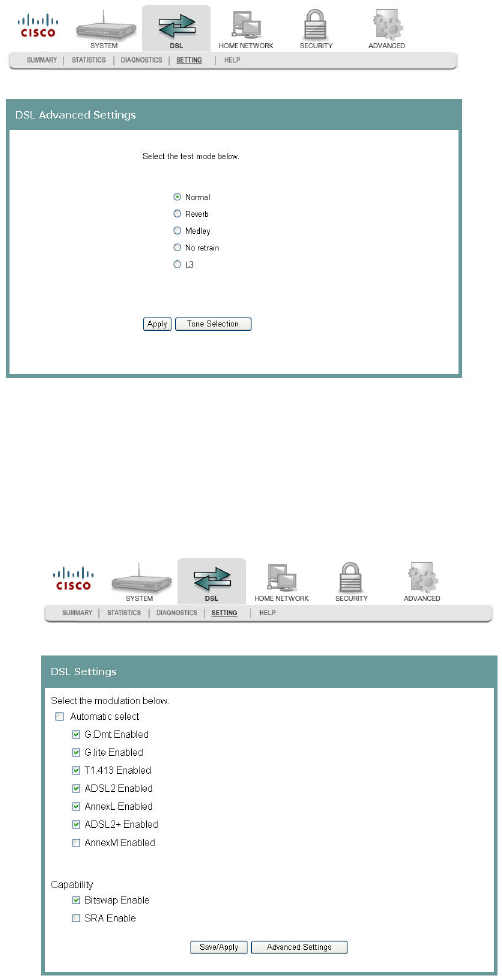
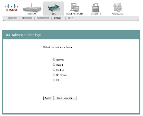
DSL Advanced Settings
The DSL Advanced Settings screen allows you to select a test mode.
Path: DSL > Setting > Advanced Settings
Configuring DSL Advanced Settings
To configure the DSL advanced settings, complete the following steps.
1Click DSL on the main screen. The Summary screen opens by default.
2Click the Setting tab. The DSL Settings screen opens.
3-6-2009 Draft
Cha
p
te
r
4 DSL Confi
g
uration
92 4030765 Rev 01
3Click Advanced Settings. The DSL Advanced Settings screen opens.
4Select the test mode from the following options:
Normal
Reverb
Medley
No refrain
L3
5Click Apply to configure and save the advanced settings.
3-6-2009 Draft

4030765 Rev 01 93
The Home Network tab allows you to check the home network
configuration. You use this tab to configure and check the status of the
devices connected to your home network.
5Chapter 5
Home Network Configuration
In This Chapter
Client Summary .................................................................................... 94
WAN Quick Setup................................................................................ 97
Set Top Box Quick Setup ................................................................... 101
LAN Setup ........................................................................................... 103
Wireless Summary.............................................................................. 106
Wireless Basic...................................................................................... 107
Wireless Security................................................................................. 111
Wireless MAC Filtering ..................................................................... 116
Wireless Bridge ................................................................................... 120
Wireless Station List ........................................................................... 121
HPNA Information............................................................................. 123
HPNA Statistics Information ............................................................ 125
Home Monitoring............................................................................... 126
3-6-2009 Draft
Cha
p
te
r
5 Home Network Confi
g
uration
94 4030765 Rev 01
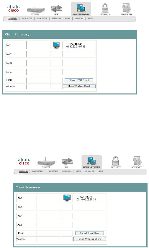
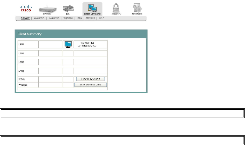
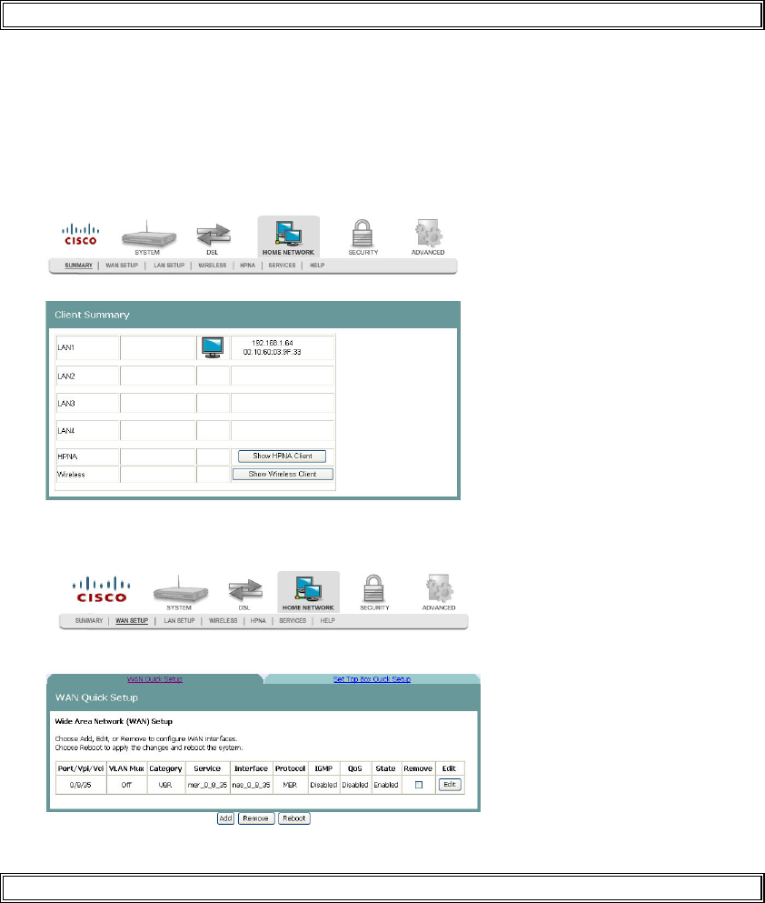
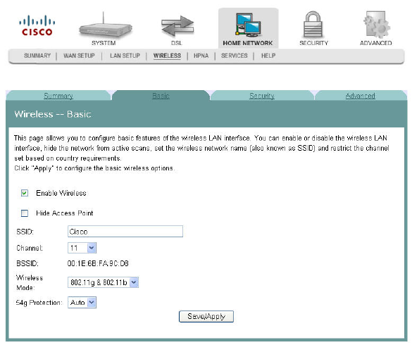
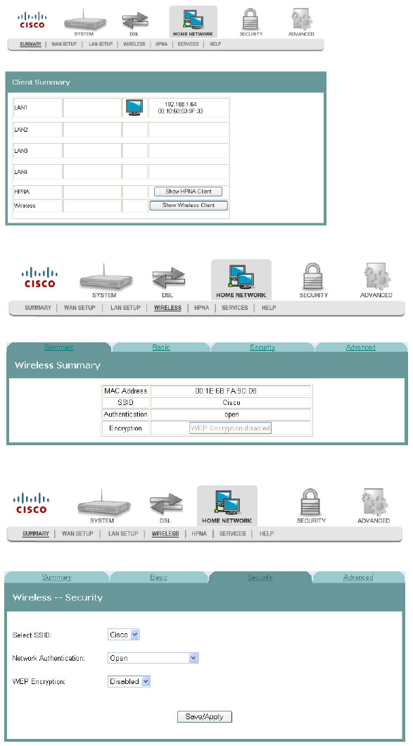
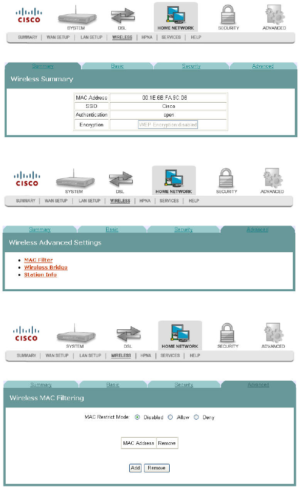
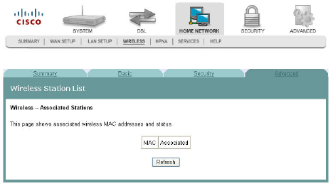
Client Summary
The Client Summary screen shows all the client devices attached to the residential
gateway. You can click Show HPNA Client to display the HPNA devices attached to
the HPNA RF interface of the residential gateway.
Path: Home Network > Summary
Updating HPNA Clients
To update the HPNA clients, complete the following steps.
1Click Home Network on the main screen.
2Click Summary. The Client Summary screen opens.
3-6-2009 Draft
Client Summary
4030765 Rev 01 95
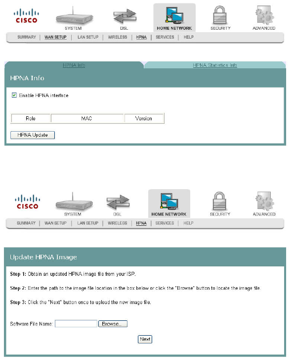
3Click Show HPNA Client. After processing, the HPNA Info screen opens.
anji for rev B
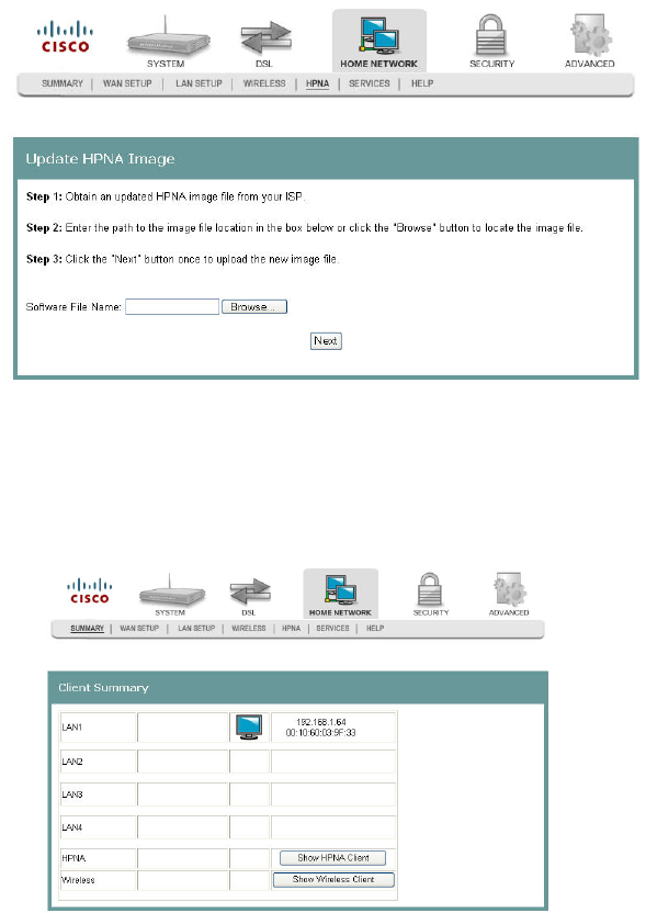
4Click HPNA Update to update the HPNA software of HPNA devices attached to
the residential gateway The Update HPNA Image window opens.
Da
5In the Software File Name field, enter the name of the file that you want to use to
update your system. You can click Browse to locate the file.
6Click Next. The software for the attached HPNA devices is updated.
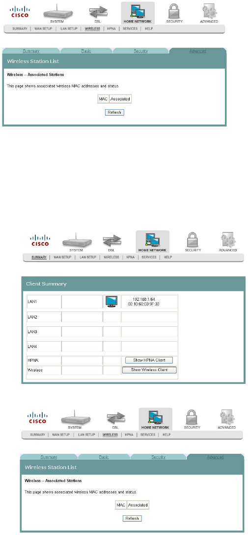
Wireless Station List
This page shows the attached clients (also known as associated stations) to the
wireless access point (AP) of the residential gateway. At this time, there is no limit to
the number of simultaneously attached devices.
Path: Home Network > Summary > Show Wireless Client
3-6-2009 Draft
Cha
p
te
r
5 Home Network Confi
g
uration
96 4030765 Rev 01
Showing Attached Clients
To show the attached clients to the wireless access point of the residential gateway,
complete the following steps.
1Click Home Network on the main screen.
2Click Summary. The Client Summary screen opens.
3Click Show Wireless Client. The Wireless Station List screen opens.
4Click Refresh to update the list of attached clients.
3-6-2009 Draft
WAN Quick Setup
4030765 Rev 01 97
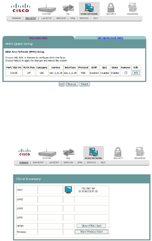
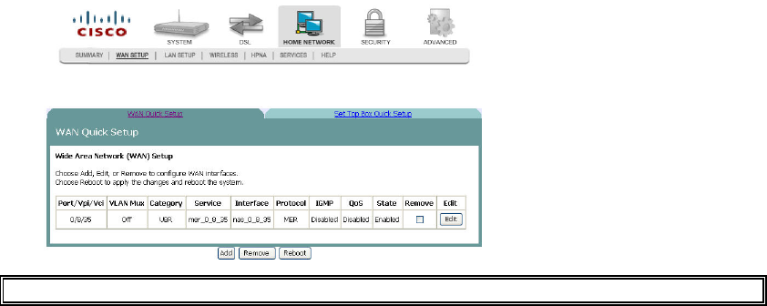
WAN Quick Setup
The WAN Quick Setup screen allows you to set up wide area network (WAN)
connections and settings, such as virtual channel identifiers (VCi), virtual path
identifiers (VPI), and quality of service (QoS).
Path: Home Network > WAN Setup > WAN Quick Setup
Configuring the WAN Interface (PPPoE Broadband Type)
To configure a WAN interface with the PPP over Ethernet (PPPoE) broadband type,
complete the following steps.
1Click Home Network on the main screen. The Client Summary screen opens.
3-6-2009 Draft
Cha
p
te
r
5 Home Network Confi
g
uration
98 4030765 Rev 01
2Click WAN Setup. The WAN Quick Setup screen opens.
Q. to reviewers click edit or add to see the next fields.
3In the Broadband Type field, select DSL.
4In the DSL Mode field, select ATM. More fields populate on the screen.
5Complete the following fields on the screen as follows:
Note: This configuration is an example of a specific setting for the residential
gateway. Your values may differ depending upon your service provider.
aIn the Broadband Connect Type field, select PPP over Ethernet (PPPoE).
bIn the Encapsulation Mode field, select LLC/SNAP - Bridging.
cCheck the VLAN Mux - Enable Multiple Protocols Over a Single PVC
check box.
dIn the PPP Username: field, enter the user name for the point-to-point
protocol.
eIn the PPP Password: field, enter the pasword for the point-to-point protocol.
fIn the PPPoE Service Name: field, enter the name for the point-to-point over
Ethernet service.
gIn the Authentication Method field, select auto from the drop-down list. Auto
turns on authentication automatically.
hIn the VPI field, enter the virtual path identifier (VPI). Values are: 0 to 65535
iIn the VCI field, enter the virtual channel identifier (VCI). Values are:
0 to 65535
jIn the Service Category field, select UBR Without PCR.
kIn the Authentication Method field, select AUTO.
lSelect the Enable IGMP Multicast check box.
mSelect the Enable WAN Service check box.
6Click Add.
7Click Reboot. This action reboots the residential gateway so that the WAN setup
configuration takes effect.
3-6-2009 Draft
WAN Quick Setup
4030765 Rev 01 99
Configuring the WAN Interface (MER Broadband Type)
To configure a WAN interface for MAC Encapsulation Routing (MER) broadband
type, complete the following steps.
1Click Home Network on the main screen. The Client Summary screen opens.
2Click WAN Setup. The WAN Quick Setup screen opens.
Q. to reviewers: Need to click Add or Edit to see this screen.
3Click Add or Edit.
<Need populated screen screen>
4In the Broadband Type field, enter DSL.
5In the DSL Mode field, select ATM. More fields populate on the screen.
6Complete the following fields on the screen as follows:
Note: This configuration is an example of a specific setting for the residential
gateway. Your values may differ depending upon your service provider.
aIn the Broadband Connect Type field, select MAC Encapsulation Routing
(MER).
bIn the Encapsulation Mode field, select LLC/SNAP - Bridging.
cSelect the VLAN Mux - Enable Multiple Protocols Over a Single PVC check
box.
dIn the VLAN ID[0-4095]: field, enter an ID for the VLAN. Values are 0-4095.
eIn the VPI field, enter the virtual path identifier (VPI). Values are: 0 to 65535
fIn the VCI field, enter the virtual channel identifier (VCI). Values are: 0 to
65535
gIn the the Service Category field, select UBR Without PCR.
hSelect the Enable Quality of Service check box.
iSelect the Obtain an IP address automatically option.
jSelect the Obtain default gateway automatically option.
kSelect the Obtain DNS server addresses automatically option.
3-6-2009 Draft
Cha
p
te
r
5 Home Network Confi
g
uration
100 4030765 Rev 01
lSelect the Enable IGMP Multicast check box.
mSelect the Enable WAN Service check box.
7Click Add.
8Click Reboot. This action reboots the residential gateway so that the WAN setup
configuration takes effect.
3-6-2009 Draft
Set Top Box Quick Setup
4030765 Rev 01 101
Set Top Box Quick Setup
The Set Top Box Quick Setup screen allows you to quickly configure set-top box
permanent virtual circuits (PVCs) and DHCP option 60 parameters.
Path: Home Network > WAN Setup > Set Top Box Quick Setup
Q. to reviewers Need populated screen
Configuring a Quick Set Up for a Set-Top
To quickly configure set-top box permanent virtual circuits (PVCs) and DHCP
option 60 parameters, complete the following steps.
1Click Home Network on the main screen. The Client Summary screen opens.
2Click WAN Setup. The WAN Quick Setup screen opens with the WAN Quick
Setup tab in the forefront.
3Click the Set Top Box Quick Setup tab.
Q. to reviewers: Need populated screen
4Complete the fields on the screen as follows.
3-6-2009 Draft
Cha
p
te
r
5 Home Network Confi
g
uration
102 4030765 Rev 01
Note: This configuration is an example of a specific setting for the residential
gateway. Your values may differ depending upon your service provider.
aIn the Broadband Type field, select DSL.
bIn the DSL mode field, select ATM.
cIn the Broadband Connect Type filed, select MAC Encapsulation Routing
(MER).
dIn the Encapsulation Mode field, select LLC/SNAP - BRIDGING.
eIn the VPI field, enter the virtual path identifier (VPI). Values are: 0 to 65535
fIn the VCI field, enter the virtual channel identifier (VCI). Values are:
0 to 65535
gIn the Service Category field, select UBR Without PCR.
hIn the Enable Virtual Port Function (Configure following parameter if the Set
Top Box has been installed) field, enable the check box.
iIn the Group Name field, enter a descriptive name for the virtual port group.
jIn the Automatically Add Clients With the following DHCP Vendor IDs
field, enter the DHCP option 60 string of the attached set-top boxes.
5Click Save/Reboot to save your changes.
3-6-2009 Draft
LAN Setup
4030765 Rev 01 103
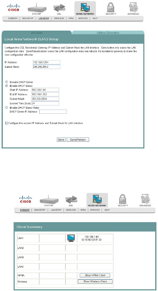
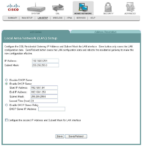
LAN Setup
The Local Area Network (LAN) Setup screen allows users to set up LAN settings
such as dynamic host configuration protocol (DHCP), Internet gateway multi-cast
protocol (IGMP), and universal plug and play (UPnP).
Path: Home Network > LAN Setup
Configuring the LAN Interface
To configure the LAN interface, complete the following steps.
1Click Home Network on the main screen. The Client Summary screen opens.
3-6-2009 Draft
Cha
p
te
r
5 Home Network Confi
g
uration
104 4030765 Rev 01
2Click LAN Setup. The Local Area Network (LAN) setup screen opens.
3In the IP Address field, enter the IP address for the residential gateway.
4In the Subnet Mask field, enter the subnet mask for the residential gateway.
5Do you want to enable UPnP?
If yes, check the Enable UPnP check box.
If no, uncheck the Enable UPnP check box.
6Do you want to Enable the DHCP server?
If yes, select Enable DHCP Server, and go to step 7.
If no, select Disable DHCP Server, and go to step 8.
7Under Enable DHCP server, enter the following information:
aIn the Start IP Address field, enter the first IP address in the range for the
DHCP IP address lease pool.
bIn the End IP Address field, enter the last IP address in the range for the
DHCP IP address lease pool.
cIn the Subnet Mask field, enter the subnet mask for the DCHP server.
dIn the Leased Time (hour) field, enter the duration of the DHCP lease
address.
8Do you want to configure a second IP address and subnet mask for the LAN
interface?
If yes, check the Configure the second IP Address and Subnet Mask for
LAN interface check box. The screen populates with another IP address and
subnet mask field. Go to step 9.
If no, uncheck the Configure the second IP Address and Subnet Mask for
LAN interface check box. Go to step 10.
3-6-2009 Draft
LAN Setup
4030765 Rev 01 105
9Under Configure the second IP Address and Subnet Mask for LAN interface,
enter the following information.
aIn the IP Address field, enter the IP address for the residential gateway.
bIn the Subnet Mask field, enter the subnet mask for the residential gateway.
10 Click Save to save the changes or click Save/Reboot to save the changes and
reboot the residential gateway.
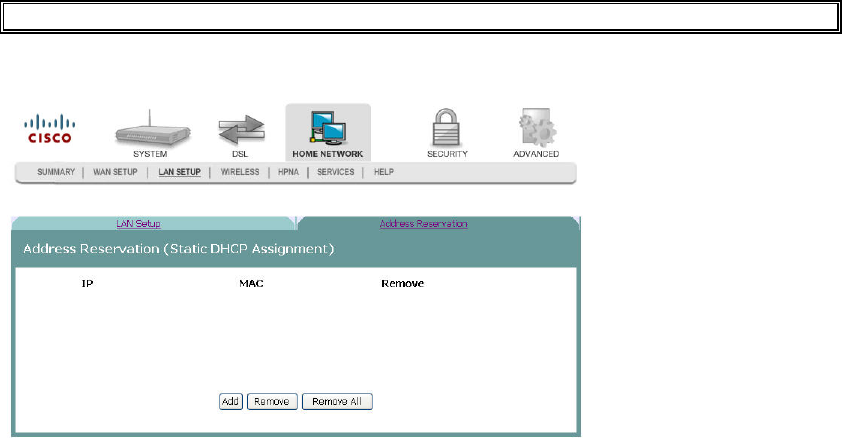
Address Reservation
The Address Reservation screen..
Q. to reviewers: Need info
Path: Home Network > LAN Setup > Address Reservation
3-6-2009 Draft
Cha
p
te
r
5 Home Network Confi
g
uration
106 4030765 Rev 01
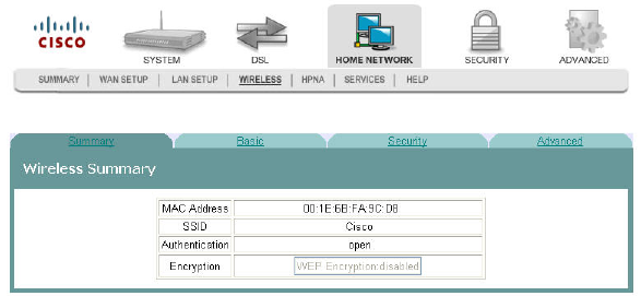
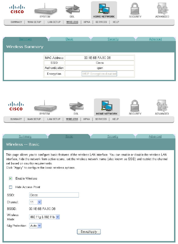
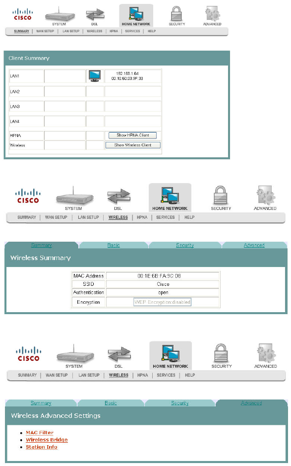
Wireless Summary
The Wireless Summary screen shows the MAC address and security information for
the wireless connection.
Path: Home Network > Wireless>Summary
3-6-2009 Draft
Wireless Basic
4030765 Rev 01 107
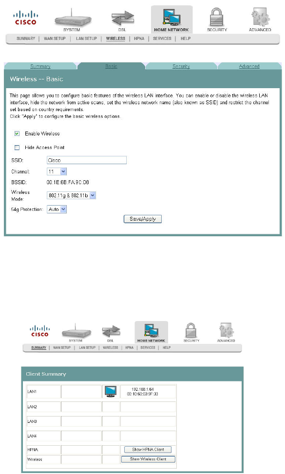
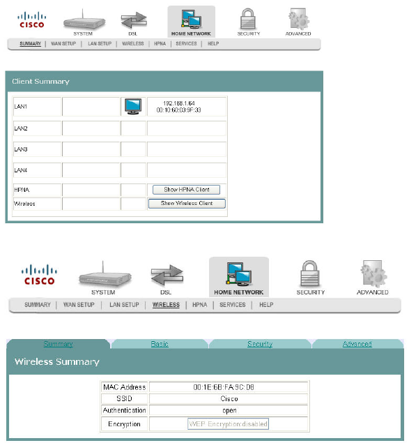
Wireless Basic
The Wireless -- Basic screen allows you to configure the basic features of the wireless
LAN interface. You can enable or disable the LAN interface, hide the network from
active scans, enter a name for the wireless network, and restrict the channel set based
on coutry requirements.
Path: Home Network > Wireless > Basic
Enabling the Wireless Network
To enable the wireless network, complete the following steps.
1Click lick Home Network on the main screen. The Client Summary screen opens.
3-6-2009 Draft
Cha
p
te
r
5 Home Network Confi
g
uration
108 4030765 Rev 01
2Click Wireless. The Wireless Summary screen opens.
3Click Basic. The Wireless Basic screen opens.
4Check the Enable Wireless check box to enable the wireless network. The screen
populates with additional fields.
5Do you want to prevent other wireless clients from communicating with the
wireless access point (AP) of the residential gateway?
If yes, check the Hide Access Point check box. This feature prevents any
other wireless client from communicating with the access point of the
residential gateway (or disables the wireless connection).
If no, uncheck the Hide Access Point check box.
6In the SSID field, enter the service set identifier (SSID).
7From the Channel drop-down list, select Auto or a channel from 1 to 11.
8In the Wireless Mode field, select the wireless mode from the drop-down list:
802.11g & 802.11b - Allows you to mix Wireless-B with Wireless-G
equipment, but you will lose the higher performance speeds of Wireless-G.
3-6-2009 Draft
Wireless Basic
4030765 Rev 01 109
802.11g only - Features the same benefits as Wireless-B, but offers 5 times the
speed at up to 54 Mbps. Wireless-G currently offers the best combination of
performance and value. You can mix Wireless-B with Wireless-G equipment,
but you will lose the higher performance speeds of Wireless-G.
802.11b only - Operates on the 2.4GHz frequency band and can transmit data
at speeds of up to 11 Mbps within a range of up to 100-150 feet. Wireless
range can be affected by reflective or signal-blocking obstacles, such as
mirrors, walls, devices and location, whether indoors or outdoors.
9In the 54g Protection field, select Auto or Off. Do not disable 54g Protection if
there is a possibility that a 802.11b device may need to use your wireless
network.
Note: 54g Protection allows 802.11g and 802.11b devices to co-exist in the same
network without “speaking” at the same time. In Auto Mode, the wireless device
will use RTS/CTS to improve 802.11g performance in mixed 802.11g/802.11b
networks. Turn protection off to maximize 802.11g throughput under most
conditions.
10 Click Save/Apply to enable the wireless network.
Disabling the Wireless Network
To disable the wireless network, complete the following steps.
1Click lick Home Network on the main screen. The Client Summary screen opens.
2Click Wireless. The Wireless Summary screen opens.
3-6-2009 Draft
Cha
p
te
r
5 Home Network Confi
g
uration
110 4030765 Rev 01
3Click Basic. The Wireless Basic screen opens.
4Uncheck the Enable Wireless check box. The wireless network fields are
removed from the screen.
5Click Save/Apply to disable the wireless network.
3-6-2009 Draft
Wireless Security
4030765 Rev 01 111
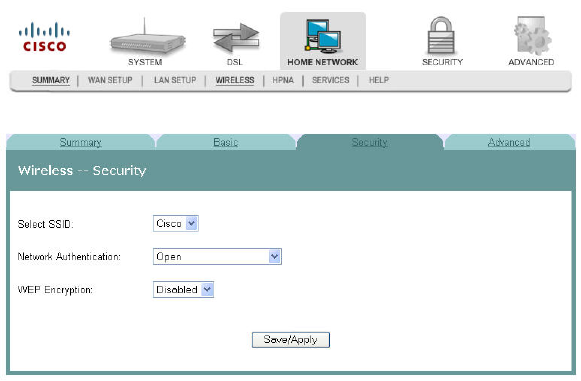
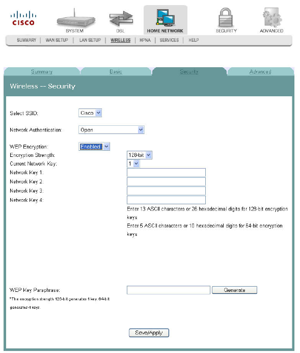
Wireless Security
The Wireless Security screen allows you to configure security features of the wireless
LAN interface. You can set the network authentication method, select data
encryption, specify whether a network key is required to authenticate to this
wireless network, and specify the encryption strength.
Path: Home Network > Wireless > Security
WEP Encryption Disabled
Securing Your Wireless Network with WEP
WEP is a security protocol for wireless networks. WEP provides security by
encrypting data over radio waves so that it is protected as it is transmitted from one
end point to another. A shared key (similar to a password) is used to allow
communication between the computers and the residential gateway. WEP offers a
basic, but satisfactory level of security for wireless data transmission.
To secure your wireless network with Wireless Equivalent Privacy (WEP), complete
the following steps.
3-6-2009 Draft
Cha
p
te
r
5 Home Network Confi
g
uration
112 4030765 Rev 01
1Click Home Network on the main screen. The Client Summary screen opens.
2Click Wireless. The Wireless Summary screen opens.
3Click Security. The Wireless -- Security screen opens.
4In the Select SSID field, use the drop-down list to choose an option for the
service set identifier (SSID).
Note: You can add options to this drop-down list on the Wireless -- Basic screen.
5In the Network Authentication field, choose one of these two options for the
authentication method.
Open. All devices may access the wireless network. (Preferred Option).
3-6-2009 Draft
Wireless Security
4030765 Rev 01 113
Shared. Only devices configured with the 64 bit or 128 Bit Key may access the
wireless network.
6In the WEP Encryption field, select Enabled. The Wireless -- Security screen
populates with more fields.
7In the Encryption strength field, choose one of the following options:
64-bit. Secures your network by 64-bit (10 hex digit) encryption of all traffic
using a static key.
128-bit. Secures your network by 128-bit (26 hex digit) encryption of all traffic
using a static key.
Attention: These settings must be identical to your wireless client devices.
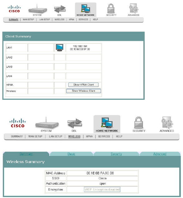
8Do you want the system to generate the network key for you?
If yes, go to step 11.
If no, you must enter your own network key(s) in the field provided. Go to
step 9.
9In the Current Network Key field, select a network key from the drop-down list.
Values are: 1, 2, 3, or 4.
10 In the Network Key 1 field, enter the network key you wish to you use.
11 Based on the encryption strength you chose in step 7, do one of the following.
3-6-2009 Draft
Cha
p
te
r
5 Home Network Confi
g
uration
114 4030765 Rev 01
For 64-bit encryption, repeat steps 9 and 10 for keys 2 through 4 if you use 64-
bit encryption. If you use 128-bit encryption, only one network key is
required. Go to step 14.
For 128-bit encryption, only one network key is used. Go to step 13.
12 In the WEP Key Paraphrase field, enter your information as follows based on 64-
bit or 128-bit encryption strength:
For 64-bit encryption strength, enter a passphrase (1 to 31 characters) and
click Generate. Four keys are generated based on the passprhase.
For 1280bit encryption, enter a passphrase (1 to 31 characters) and click
Generate. A single key is generated based on the passprhase.
13 Click Save/Apply.
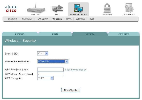
Securing Your Wireless Network with Encryption Keys
If you choose WPA-PSK (Wi-Fi Protected Access-PreShared Key) as the network
authentication method, you can secure your network by encrypting all traffic using a
pre-shared dynamic key.
To secure your wireless network with a preshared dynamic key, complete the
following steps.
1Click Home Network on the main screen. The Client Summary screen opens.
2Click Wireless. The Wireless Summary screen opens.
3-6-2009 Draft
Wireless Security
4030765 Rev 01 115
3Click Security. The Wireless -- Security screen opens.
Cli
4In the Network Authentication field, select WPA-PSK from the drop-down list.
5In the WPA Pre-Shared Key field, enter a shared Key (8-63 characters). The
system will periodically generate a dynamic key based on the shared key.
6In the WPA Group Rekey Interval field, enter the group key renewal time
period. This time defines how often the dynamic key is regenerated
7In the WPA Encryption field, select the encryption from the drop-down list.
8Click Save/Apply to save your settings.
3-6-2009 Draft
Cha
p
te
r
5 Home Network Confi
g
uration
116 4030765 Rev 01
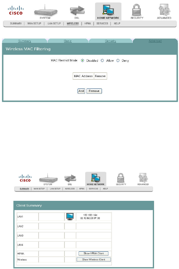
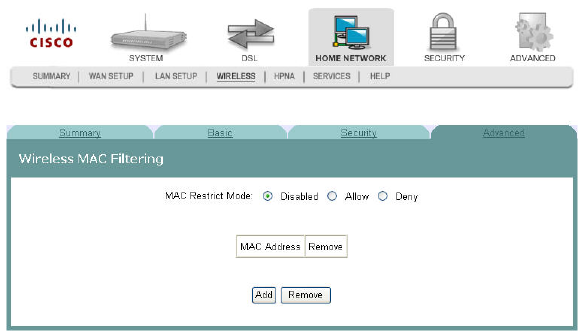
Wireless MAC Filtering
The Wireless -- MAC Filtering screen allows you to allow or block certain wireless
clients from accessing the residential gateway. If you know the MAC address of the
client you want to block, you can use this screen to provide access to the residential
gateway or block that client from accessing it.
Path: Home Network > Wireless > Advanced > MAC Filter
Allowing Wireless Clients to Access the Residential Gateway
You can allow wireless clients to access the residential gateway if you know the
client's MAC address. MAC restrict mode must be enabled. To allow wireless clients
to access the residential gateway, complete the following steps.
1Click Home Network on the main screen. The Client Summary screen opens.
3-6-2009 Draft
Wireless MAC Filtering
4030765 Rev 01 117
2Click Wireless. The Wireless Summary screen opens.
3Click Advanced. The Wireless Advanced Settings screen opens.
4Click MAC Filter. The Wireless MAC Filtering screen opens.
5In the MAC Restrict Mode field, click Allow to enable the MAC restrict mode.
6Click Add. The Wireless -- MAC Filter screen opens.
7In the MAC Address field, enter the MAC address of the client that you want to
allow access to the residential gateway.
8Click Save/Apply to allow this wireless client to access the residential gateway.
3-6-2009 Draft
Cha
p
te
r
5 Home Network Confi
g
uration
118 4030765 Rev 01
Blocking Wireless Clients
You can block wireless clients from accessing the residential gateway if you know
the client's MAC address. MAC restrict mode must be enabled. To prevent wireless
clients from accessing the residential gateway, complete the following steps.
1Click Home Network on the main screen. The Client Summary screen opens.
2Click Wireless. The Wireless Summary screen opens.
3Click Advanced. The Wireless Advanced Settings screen opens.
3-6-2009 Draft
Wireless MAC Filtering
4030765 Rev 01 119
4Click MAC Filter. The Wireless MAC Filtering screen opens.
5In the MAC Restrict Mode field, click Deny to enable the MAC restrict mode.
6Click Add. The Wireless -- MAC Filter screen opens.
7In the MAC Address field, enter the MAC address of the client that you want to
prevent from accessing the residential gateway.
8Click Save/Apply to prevent this wireless client from accessing the residential
gateway.
3-6-2009 Draft
Cha
p
te
r
5 Home Network Confi
g
uration
120 4030765 Rev 01
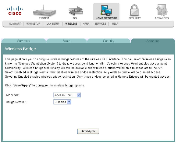
Wireless Bridge
Wireless LAN Bridging (also referred to as a Wireless Distribution System, WDS)
refers to two or more 802.11 access points that send traffic between them (from
access point to access point) as opposed to between access point and a client
computer.
The Wireless Bridge screen allows you to configure the wireless bridge features of
the wireless LAN interface as follows:
Select Wireless Bridge for the AP mode to disable access point functionality.
Select Access Point for the AP mode to enables access point functionality.
Wireless bridge functionality will still be available and wireless stations will be
able to associate to the AP.
Select Disabled for the Bridge Restrict field to disable wireless bridge restriction
and any device can communicate with the residential gateway over the wireless
bridge.
Select Enabled for the Bridge Restrict field to enable wireless bridge restriction to
restrict the bridges that can communicate with the residential gateway over the
wireless interface.
Path: Home Network > Wireless > Advanced > Wireless Bridge
3-6-2009 Draft
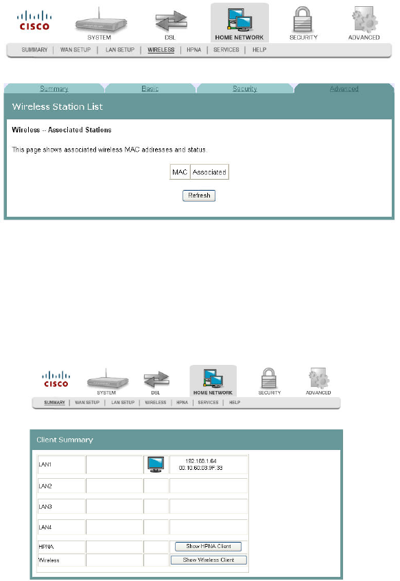
Wireless Station List
4030765 Rev 01 121
Wireless Station List
This page shows the attached clients (also known as associated stations) to the
wireless access point (AP) of the residential gateway. At this time, there is no limit to
the number of simultaneously attached devices.
Path: Home Network > Summary > Show Wireless Client
Showing Attached Clients
To show the attached clients to the wireless access point of the residential gateway,
complete the following steps.
1Click Home Network on the main screen.
2Click Summary. The Client Summary screen opens.
3-6-2009 Draft
Cha
p
te
r
5 Home Network Confi
g
uration
122 4030765 Rev 01
3Click Show Wireless Client. The Wireless Station List screen opens.
4Click Refresh to update the list of attached clients.
3-6-2009 Draft
HPNA Information
4030765 Rev 01 123
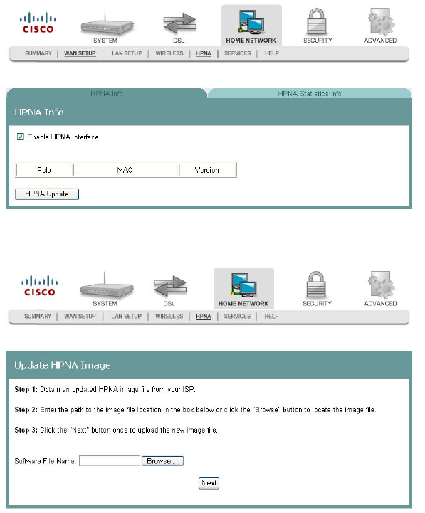
HPNA Information
The HPNA Info screen allows you to view the HPNA devices connected to the
residential gateway.
Path: Home Network > HPNA > HPNA Info
Updating HPNA Information
To update the HPNA information, complete the following steps.
1Click Home Network on the main screen. The Client Summary screen opens.
3-6-2009 Draft
Cha
p
te
r
5 Home Network Confi
g
uration
124 4030765 Rev 01
2Click Show HPNA Client. After a moment of processing, the HPNA Info screen
opens.
3Click HPNA Update to to update the HPNA software of HPNA devices attached
to the residential gateway The Update HPNA Image window opens.
4In the Software File Name field, enter the name of the file that you want to use to
update your system. You can click Browse to locate the file.
5Click Next. The software for the attached HPNA devices is updated.
3-6-2009 Draft
HPNA Statistics Information
4030765 Rev 01 125
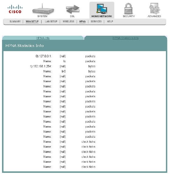
HPNA Statistics Information
The HPNA Statistics Info screen displays the statistics for the HPNA devices
connected to the residential gateway.
Path: Home Network > HPNA > HPNA Statistics Info
3-6-2009 Draft
Cha
p
te
r
5 Home Network Confi
g
uration
126 4030765 Rev 01
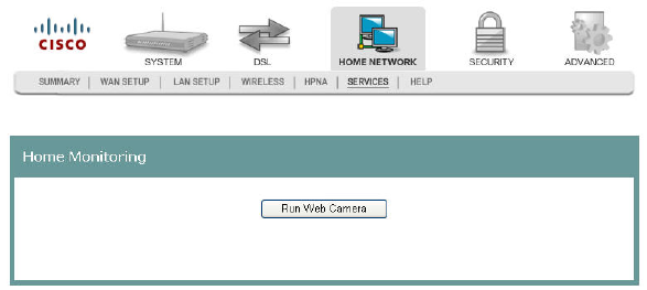
Home Monitoring
The Home Monitoring screen allows you to monitor your surroundings by attaching
a web camera to the USB port of the residential gateway. After you connect your
camera, click Run Web Camera. A popup window appears showing the camera
video output. The home monitoring feature is for local use only.
Path: Home Network > Services > Home Monitoring
3-6-2009 Draft

4030765 Rev 01 127
The Security tab allows you to check the security configuration and
modify the configuration.
Use this chapter to help you check the status of the security
configuration or make changes to the configuration.
6Chapter 6
Security Configuration
In This Chapter
MAC Filtering Setup .......................................................................... 128
Incoming IP Filtering.......................................................................... 134
Outgoing IP Filtering ......................................................................... 141
Parental Control Setup - Filtering Function.................................... 146
URL Filtering Function ...................................................................... 151
Stateful Packet Inspection.................................................................. 156
Local Certificates................................................................................. 158
Trusted CA Certificates...................................................................... 163
3-6-2009 Draft

Cha
p
te
r
6 Securit
y
Confi
g
uration
128 4030765 Rev 01
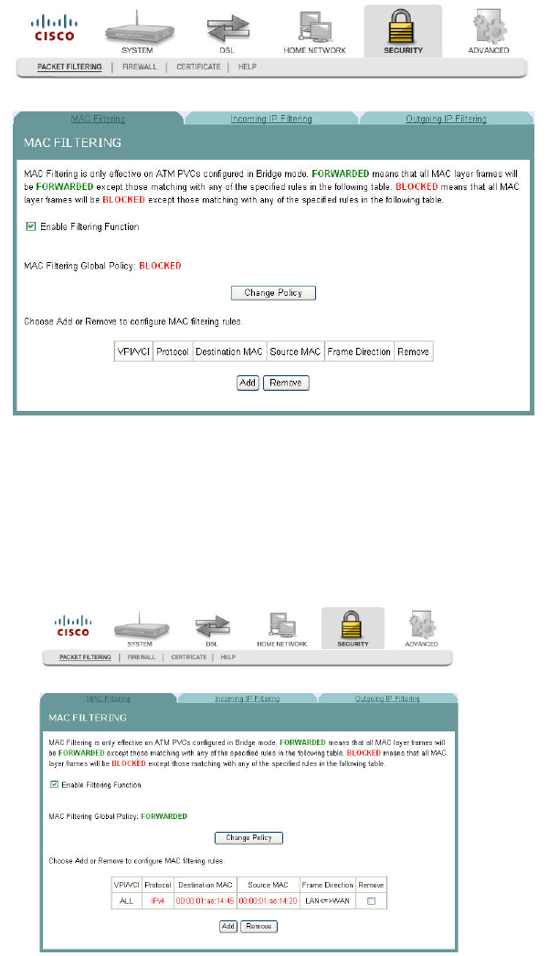
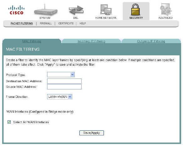
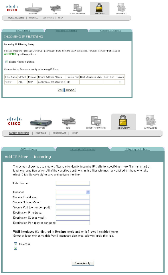
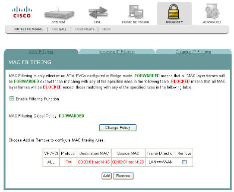
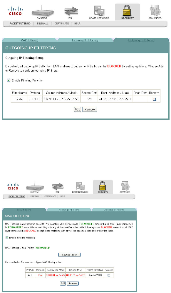
MAC Filtering Setup
The MAC Filtering Setup screen allows you to set up filters for packets containing
configured MAC addresses. With the MAC Filtering feature, you can restrict access
to certain servers based on their MAC address. MAC Filtering is only effective on
ATM PVCs configured in Bridge mode.
Path: Security > Packet Filtering > MAC Filtering
Forwarded MAC Filtering
FORWARDED means that all MAC layer frames will be FORWARDED except those
that match any of the specified rules in the following screen.
3-6-2009 Draft
MAC Filtering Setup
4030765 Rev 01 129
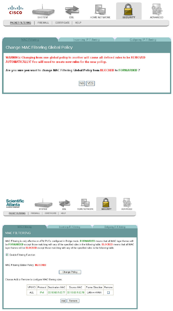
Blocked MAC Filtering
BLOCKED means that all MAC layer frames will be BLOCKED except those that
match any of the specified rules in the following screen.
Adding MAC Filtering
To add MAC Filtering, complete the following steps.
1Click Security on the main screen. The Packet Filtering tab opens by default.
2Click MAC Filtering. The MAC Filtering screen opens.
3Check the Enable Filtering Function check box.
4Cliick Add to open a blank MAC Filtering screen.
3-6-2009 Draft
Cha
p
te
r
6 Securit
y
Confi
g
uration
130 4030765 Rev 01
Cl
5In the Protocol Type field, select one of the following protocols from the drop-
down menu.
PPPoE
IPv4
IPv6
AppleTalk
IPX
NetBEUI
IGMP
6In the Destination MAC Address field, enter the frame's destination MAC
address.
7In the Source MAC Address field, enter the frame's source MAC address.
8In the Frame Direction field, select one of the following choices from the drop-
down menu:
LAN<->WAN
WAN<->LAN
3-6-2009 Draft

MAC Filtering Setup
4030765 Rev 01 131
9Do you want to select all WAN interfaces?
If yes, check the Select All WAN Interfaces check box under the WAN
Interfaces (Configured in Bridge mode only) field.
If no, uncheck the Select All WAN Interfaces check box under the WAN
Interfaces (Configured in Bridge mode only) field.
10 Click Save/Apply to add the MAC Filter.
Forwarding or Blocking MAC Layer Frames
You can change the policy on how MAC layer frames are forwarded or blocked.
FORWARDED means that all MAC layer frames will be forwarded except those
matching with any of the specified rules in the table on the screen. BLOCKED means
that all MAC layer frames will be blocked except those matching with any of the
specified rules in the table on the screen.
To change the policy on how MAC layer frames are forwarded or blocked, complete
the following steps.
1Click Security on the main screen. The Packet Filtering tab opens by default.
2Click MAC Filtering. The MAC Filtering screen opens.
3Check the Enable Filtering Function check box.
3-6-2009 Draft
Cha
p
te
r
6 Securit
y
Confi
g
uration
132 4030765 Rev 01
4Click Change Policy. The Change MAC Filtering Global Policy screen opens. In
this example, the global policy for MAC filtering is "Blocked."
5Do you want to change the Global Policy?
If yes, click Yes. If the policy is forwarded, clicking Yes changes the policy to
blocked and vise versa.
If no, click No and the policy remains unchanged.
Removing MAC Filtering
To remove a MAC filtering rule you have set up, complete the following steps.
1Click Security on the main screen. The Packet Filtering tab opens by default.
2Click MAC Filtering. The MAC Filtering screen opens.
3From the MAC Filtering screen, select Remove in the Remove column next to the
MAC filtering rule you wish to remove.
4Click Remove to remove the MAC filtering.
3-6-2009 Draft

MAC Filtering Setup
4030765 Rev 01 133
Removing MAC Filtering
To remove a MAC filtering rule you have set up, complete the following steps.
1Click Security on the main screen. The Packet Filtering tab opens by default.
2Click MAC Filtering. The MAC Filtering screen opens.
3From the MAC Filtering screen, select Remove in the Remove column next to the
MAC filtering rule you wish to remove.
4Click Remove to remove the MAC filtering.
3-6-2009 Draft
Cha
p
te
r
6 Securit
y
Confi
g
uration
134 4030765 Rev 01
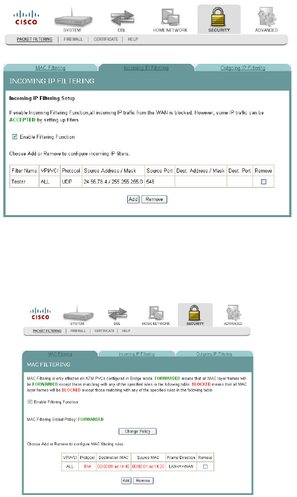
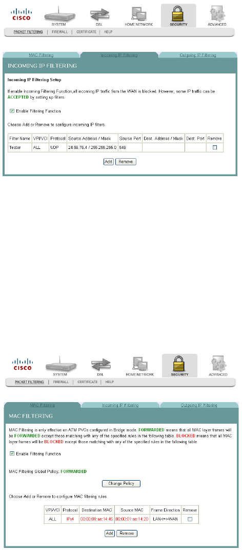
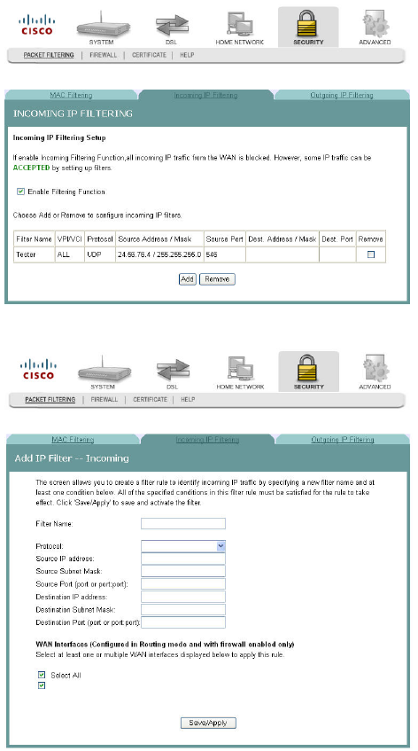
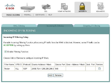
Incoming IP Filtering
By default, all incoming IP traffic from the WAN is blocked when the firewall is
enabled. However, some IP traffic can be accepted by setting up filters.
Path: Security > Packet Filtering > Incoming IP Filtering
Enabling the Filtering Function
To enable the filtering function, complete the following steps.
1Click Security on the main screen. The MAC Filtering screen opens by default.
3-6-2009 Draft
Incoming IP Filtering
4030765 Rev 01 135
2Click Incoming IP Filtering. The Incoming IP Filtering screen opens.
3Check the Enable Filtering Function check box to enable the filtering function.
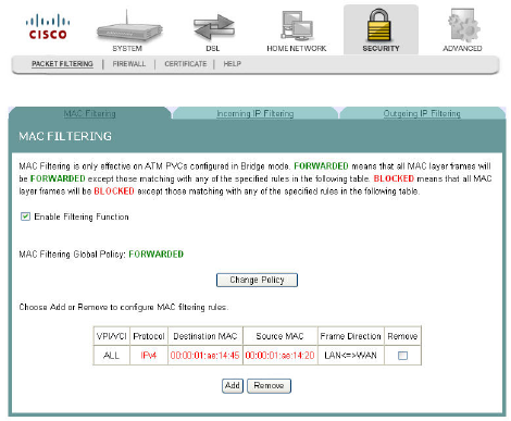
Adding an Incoming IP Filter
You can create a filter rule to identify incoming IP traffic by specifying a new filter
name and at least one condition for the filter. All of the specified conditions in this
filter rule must be satisfied for the rule to take effect.
To add an incoming IP filter, complete the following steps.
1Click Security on the main screen. The MAC Filtering screen opens by default.
3-6-2009 Draft
Cha
p
te
r
6 Securit
y
Confi
g
uration
136 4030765 Rev 01
2Select the Incoming IP Filtering tab. The Incoming IP Filtering screen opens.
3Click Add. The Add IP Filter Incoming screen opens.
4In the Filter Name field, enter the name of the filter.
5In the Protocol field, select one of the following protocols:
TCP/UDP
TCP
UDP
ICMP
6In the Source IP address field, enter the source IP address of the server sending
the incoming packets.
7In the Source Subnet Mask field, enter the subnet mask of the server sending the
incoming packets.
3-6-2009 Draft
Incoming IP Filtering
4030765 Rev 01 137
8In the Source Port field, enter the port number of the server sending the
incoming packets. You can enter one port or a range of ports using the following
format: port or port:port.
Example: 0:5 indicates ports 0 through 5.
9In the Destination IP address field, enter the destination IP address for the server
receiving the packets.
10 In the Destination Subnet Mask field, enter the subnet mask for the server
receiving the packets.
11 In the Destination Port field, enter the port number for the server receiving the
packets. You can enter one port or a range of ports using the following format:
port or port:port.
Example: 0:5 to indicates ports 0 through 5.
12 Do you want to select all of the WAN interfaces?
If yes, check the Select All field under WAN Interfaces (Configured in
Routing mode and with firewall enabled only).
If no, clear the Select All field under WAN Interfaces (Configured in Routing
mode and with firewall enabled only).
13 Click Save/Apply to add the filter.
Adding an Incoming IP Filter
You can create a filter rule to identify incoming IP traffic by specifying a new filter
name and at least one condition for the filter. All of the specified conditions in this
filter rule must be satisfied for the rule to take effect.
To add an incoming IP filter, complete the following steps.
1Click Security on the main screen. The MAC Filtering screen opens by default.
3-6-2009 Draft
Cha
p
te
r
6 Securit
y
Confi
g
uration
138 4030765 Rev 01
2Select the Incoming IP Filtering tab. The Incoming IP Filtering screen opens.
3Click Add. The Add IP Filter Incoming screen opens.
4In the Filter Name field, enter the name of the filter.
5In the Protocol field, select one of the following protocols:
TCP/UDP
TCP
UDP
ICMP
6In the Source IP address field, enter the source IP address of the server sending
the incoming packets.
3-6-2009 Draft
Incoming IP Filtering
4030765 Rev 01 139
7In the Source Subnet Mask field, enter the subnet mask of the server sending the
incoming packets.
8In the Source Port field, enter the port number of the server sending the
incoming packets. You can enter one port or a range of ports using the following
format: port or port:port.
Example: 0:5 indicates ports 0 through 5.
9In the Destination IP address field, enter the destination IP address for the server
receiving the packets.
10 In the Destination Subnet Mask field, enter the subnet mask for the server
receiving the packets.
11 In the Destination Port field, enter the port number for the server receiving the
packets. You can enter one port or a range of ports using the following format:
port or port:port.
Example: 0:5 to indicates ports 0 through 5.
12 Do you want to select all of the WAN interfaces?
If yes, check the Select All field under WAN Interfaces (Configured in
Routing mode and with firewall enabled only).
If no, clear the Select All field under WAN Interfaces (Configured in Routing
mode and with firewall enabled only).
13 Click Save/Apply to add the filter.
Removing an Incoming IP Filter
To remove an incoming IP filter, complete the following steps.
1Click Security on the main screen. The MAC Filtering screen opens by default.
3-6-2009 Draft
Cha
p
te
r
6 Securit
y
Confi
g
uration
140 4030765 Rev 01
2Select the Incoming IP Filtering tab. The Incoming IP Filtering screen opens.
3From the Incoming IP Filtering screen, select Remove in the Remove column
next to the filter you wish to remove.
4Click Remove to remove the filter.
3-6-2009 Draft
Outgoing IP Filtering
4030765 Rev 01 141
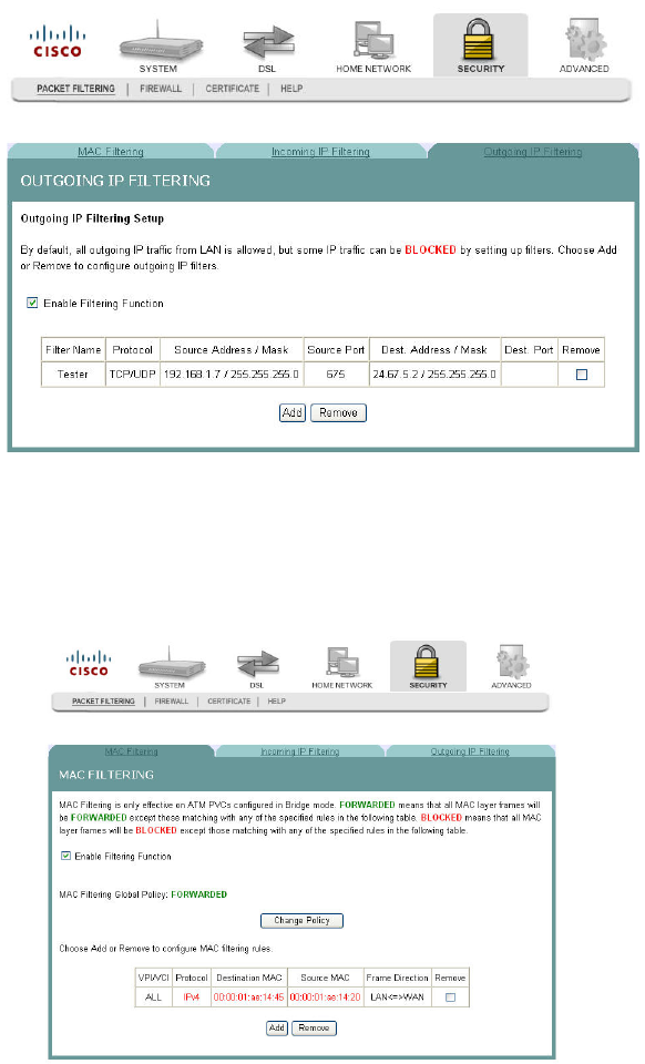
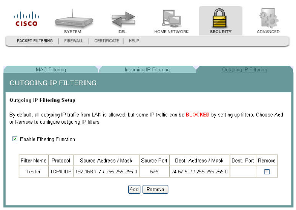
Outgoing IP Filtering
By default, all outgoing IP traffic from LAN is allowed, but some IP traffic can be
BLOCKED by setting up filters.
Path: Security > Packet Filtering > Outgoing IP Filtering
Enabling the Filtering Function
To enable the outgoing IP filtering function, complete the following steps.
1Click Security on the main screen. The MAC Filtering screen opens by default.
3-6-2009 Draft
Cha
p
te
r
6 Securit
y
Confi
g
uration
142 4030765 Rev 01
2Click Outgoing IP Filtering. The Outgoing IP Filtering screen opens.
3Check the Enable Filtering Function check box to enable the filtering function.
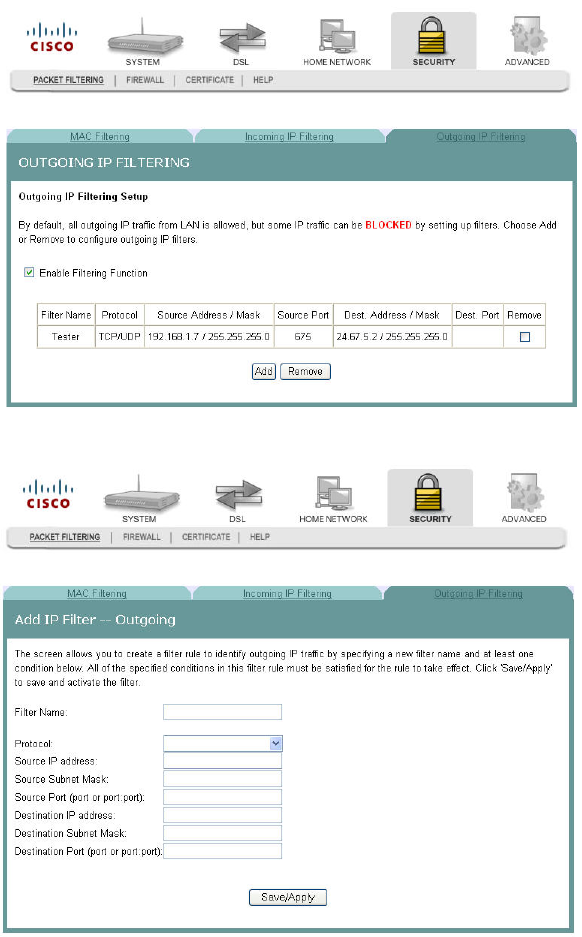
Adding an Outgoing IP Filter
To add an outgoing IP filter, complete the following steps.
1Click Security on the main screen. The MAC Filtering screen opens by default.
3-6-2009 Draft
Outgoing IP Filtering
4030765 Rev 01 143
2Select the Outgoing IP Filtering tab. The Outgoing IP Filtering screen opens.
3Click Add. The Add IP Filter Outgoing screen opens.
4In the Filter Name field, enter the name of the filter. The maximum character
length is... You cannot use blank spaces in the filter name.
5In the Protocol field, select one of the following protocols:
TCP/UDP
TCP
UDP
ICMP
6In the Source IP address field, enter the source IP address for the server sending
the incoming packets.
3-6-2009 Draft

Cha
p
te
r
6 Securit
y
Confi
g
uration
144 4030765 Rev 01
7In the Source Subnet Mask field, enter the subnet mask for the for the server
sending the incoming packets.
8In the Source Port field, enter the port number for the server sending the
incoming packets. Use the following format: port or port:port.
9In the Destination IP address field, enter the destination IP address for the server
receiving the packets.
10 In the Destination Subnet Mask field, enter the subnet mask for the server
receiving the packets.
11 In the Destination Port field, enter the port number for the server receiving the
packets. Use the following format: port or port:port.
12 Click Save/Apply to add the filter.
Removing an Outgoing IP Filter
To remove an outgoing IP filter, complete the following steps.
1Click Security on the main screen. The MAC Filtering screen opens by default.
3-6-2009 Draft
Outgoing IP Filtering
4030765 Rev 01 145
2Select the Outgoing IP Filtering tab. The Outgoing IP Filtering screen opens.
3From the Outgoing IP Filtering screen, select Remove in the Remove column
next to the filter you wish to remove.
4Click Remove to remove the filter.
3-6-2009 Draft
Cha
p
te
r
6 Securit
y
Confi
g
uration
146 4030765 Rev 01
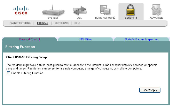
Parental Control Setup - Filtering Function
The Client IP/MAC Filtering Setup screen allows you to configure the residential
gateway to restrict access to the Internet, email, or other network services at specific
days and times. You can set time restrictions for a single computer, a range or
computers, or multiple computers.
Path: Security >Firewall > Parental Control
Adding Time of Day Restrictions
The Time of Day Restrictions screen allows you to block access to the Internet for
certain times of the day. This screen adds time of day restriction to a special LAN
device connected to the residential gateway. The browser's MAC Address
automatically displays the MAC address of the LAN device where the browser is
running. To restrict other LAN devices, select the Other MAC Address option and
enter the MAC address of the other LAN device. To find out the MAC address of a
Windows based PC, go to a command window and type ipconfig /all.
Path: Security > Firewall > Parental Control
To add time of day restrictions, complete the following steps.
3-6-2009 Draft