GemTek Technology ADV980114G DDR2201 v1 ADSL2+ Residential Gateway User Manual Manual 2
Gemtek Technology Co., Ltd. DDR2201 v1 ADSL2+ Residential Gateway Manual 2
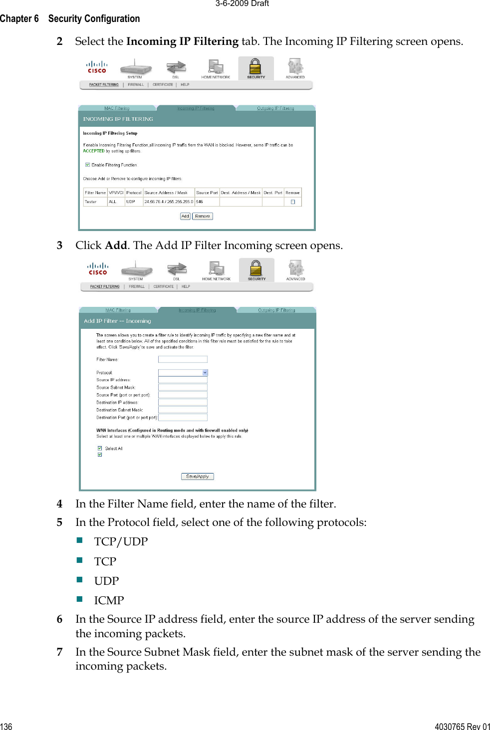
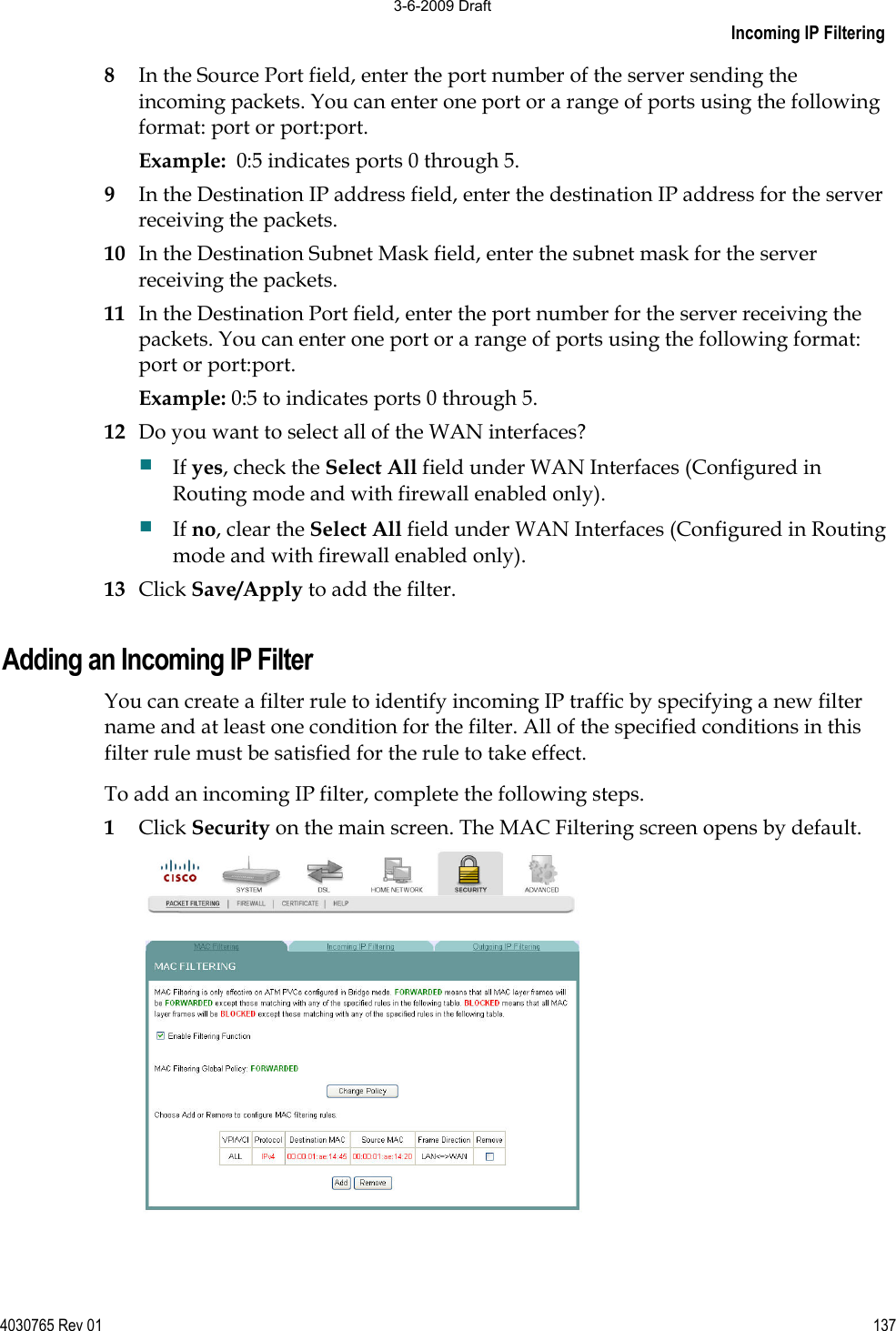
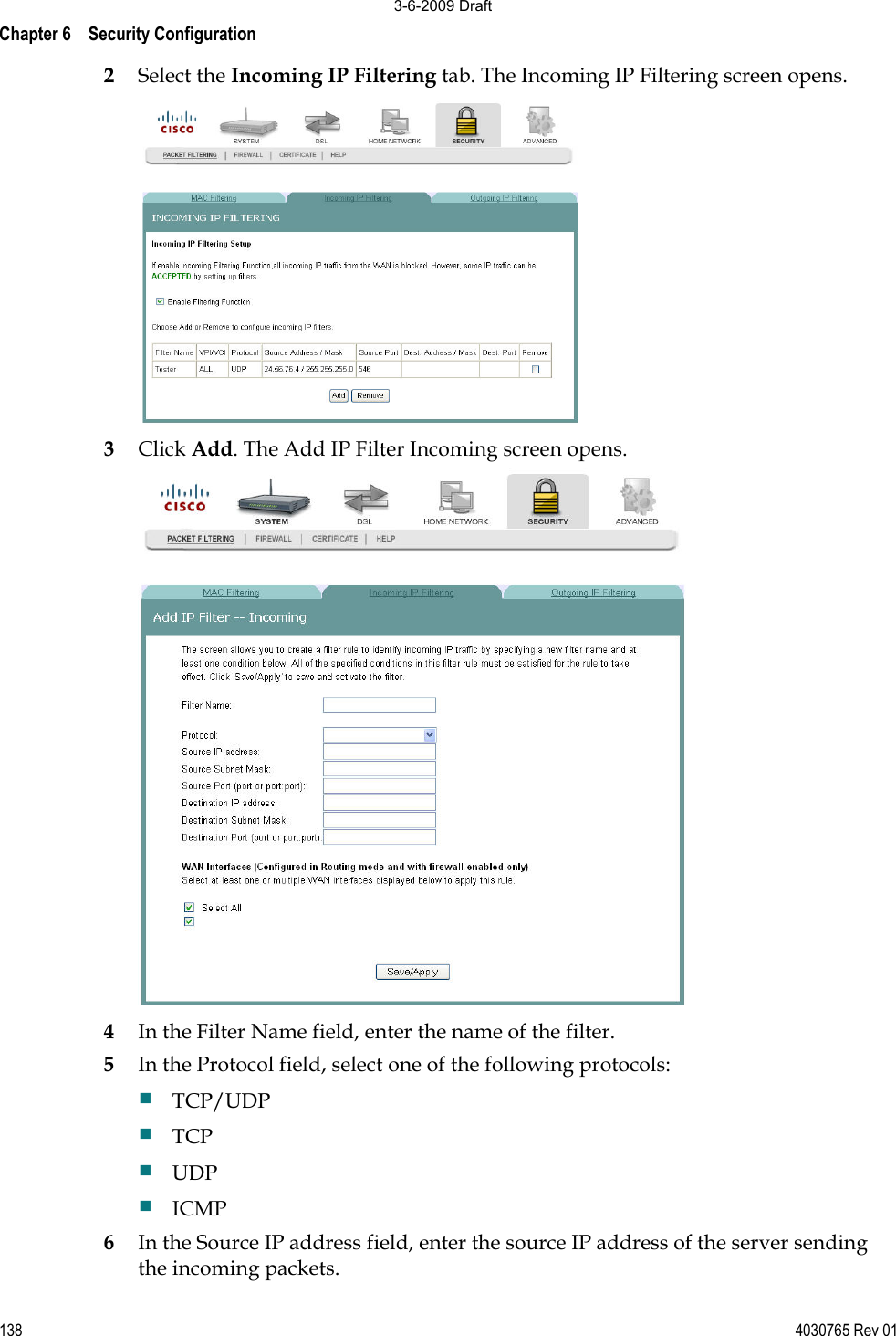
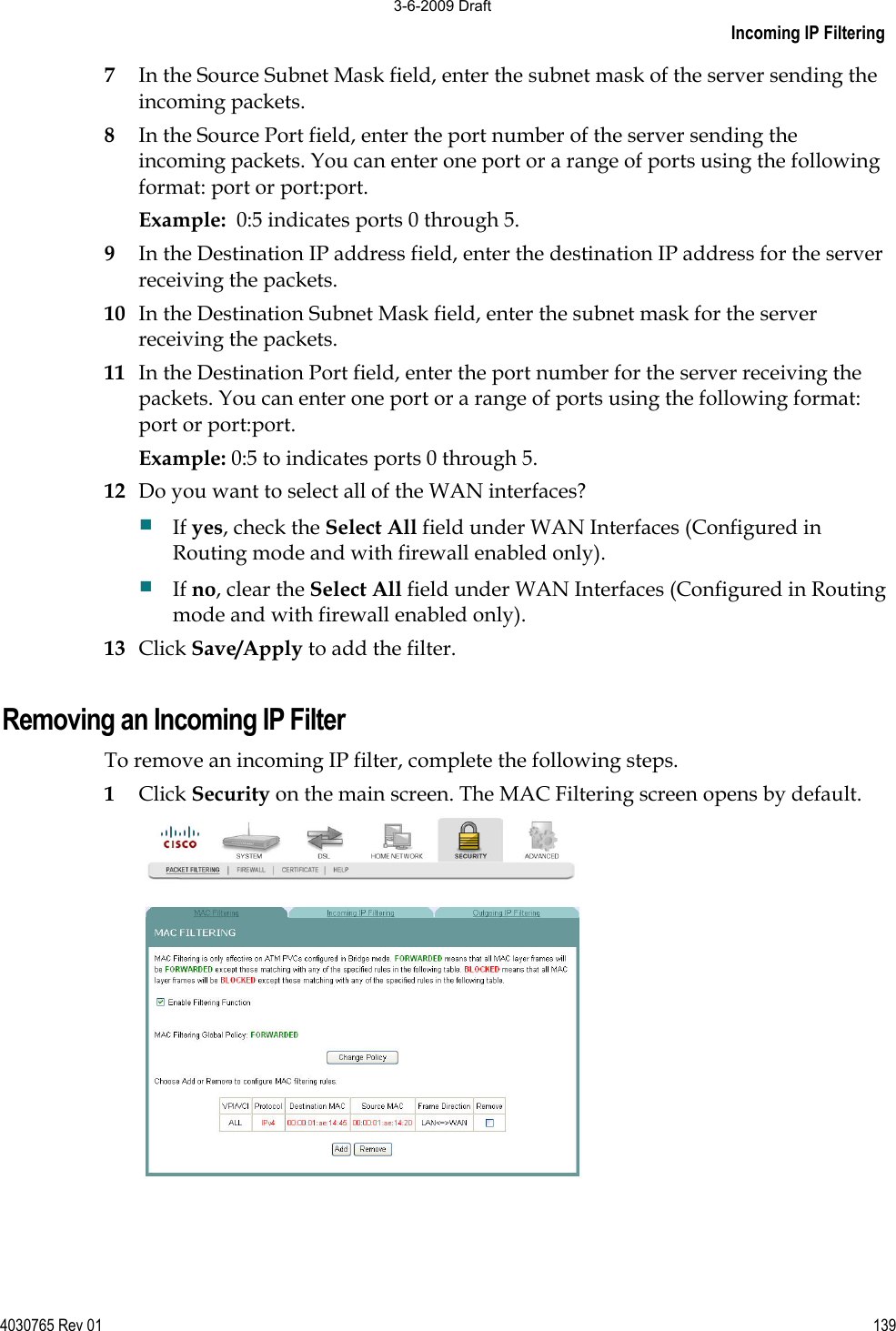
UserManual.wiki
>
GemTek Technology
>
ADV980114G User Manual
>
Manual 2
Contents
1.
Manual 1
2.
Manual 2
3.
Manual 3
Manual 2
Navigation menu
Upload a User Manual
Namespaces
Wiki Guide
HTML
PDF
Info
Views
User Manual
Discussion / Help
Navigation
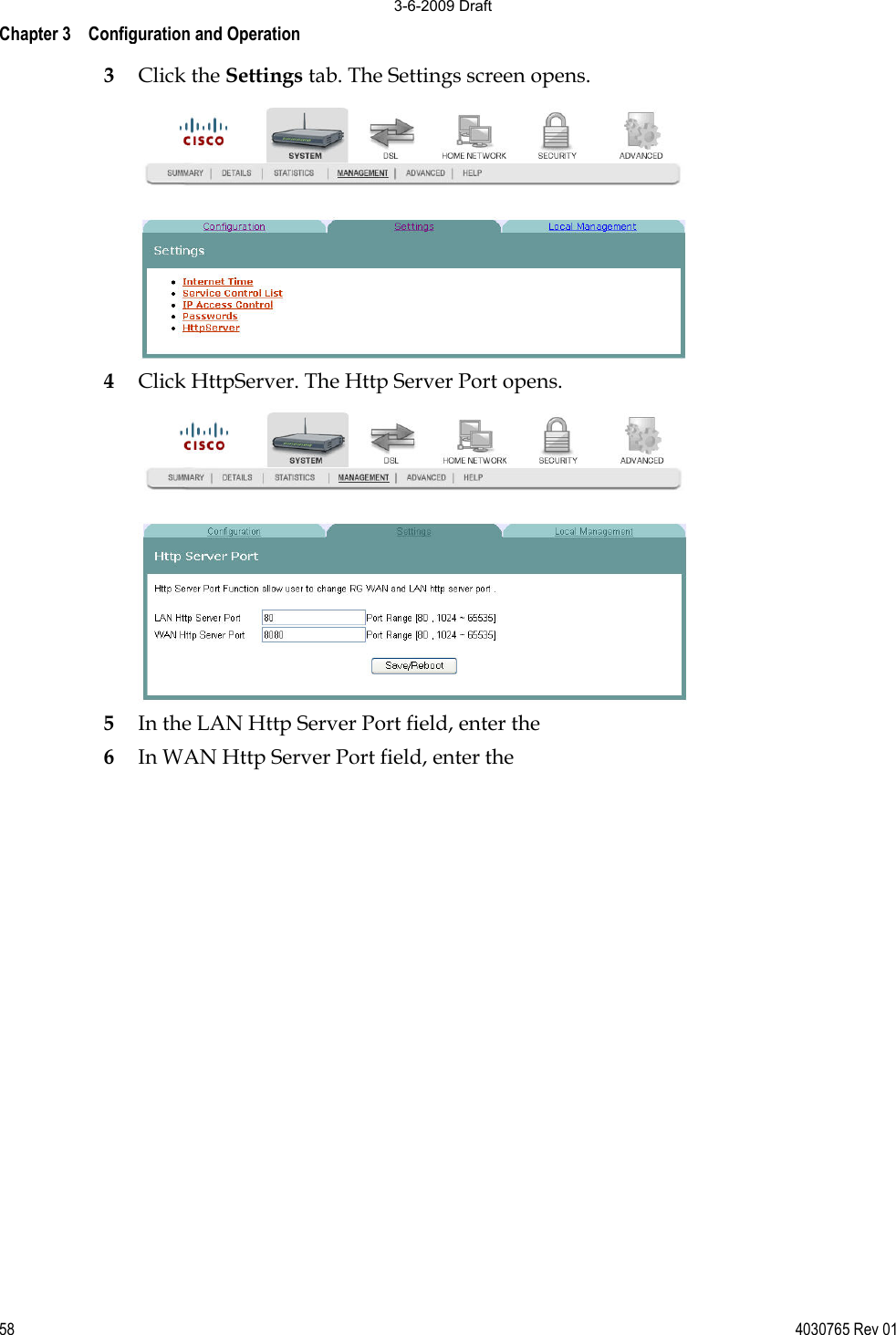
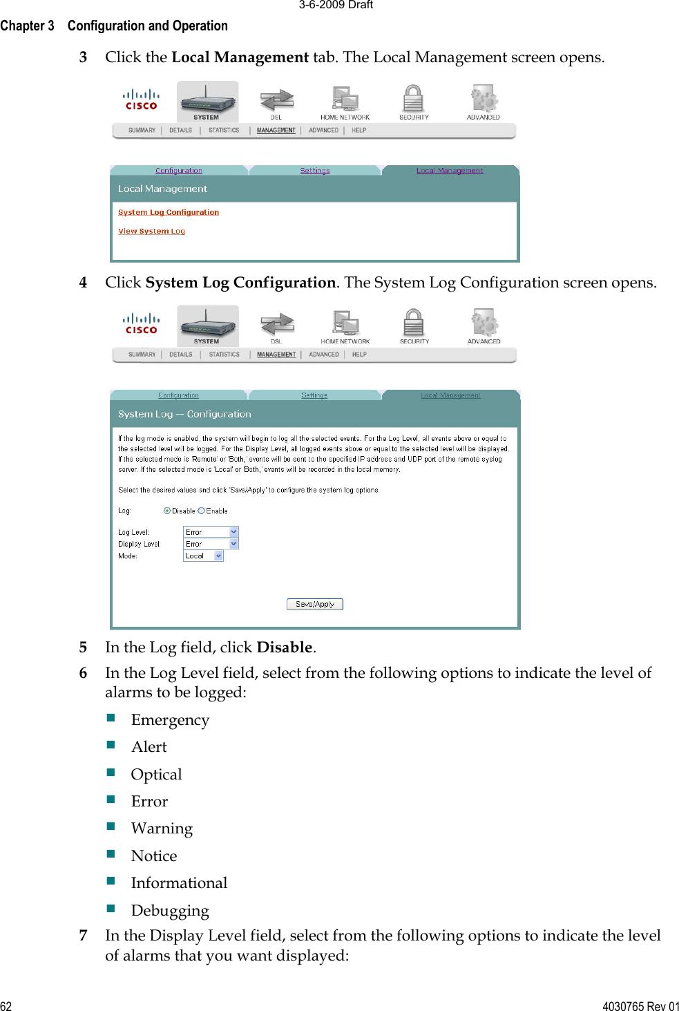
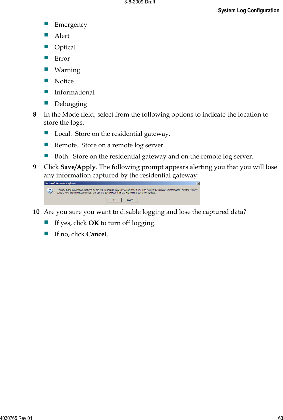
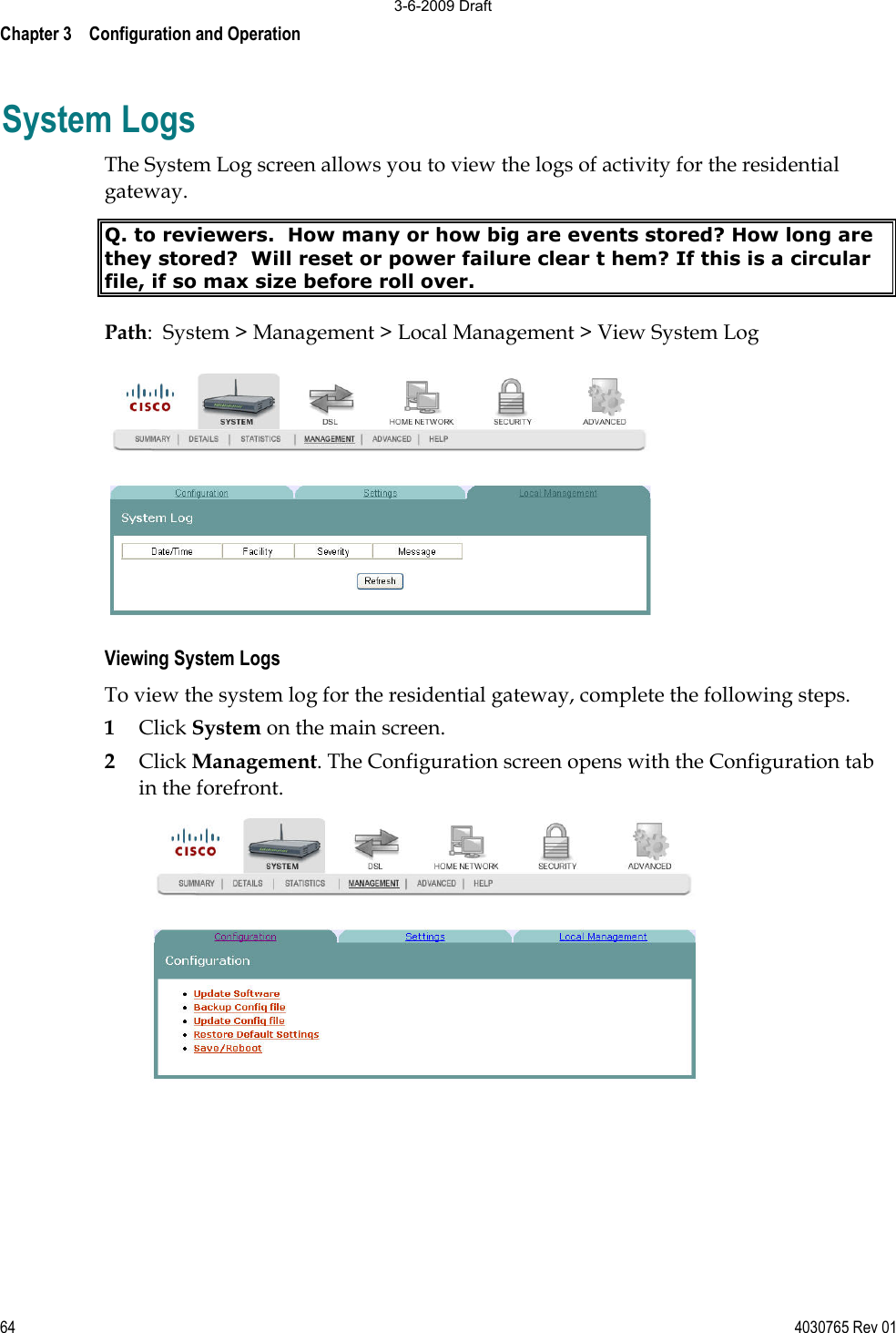
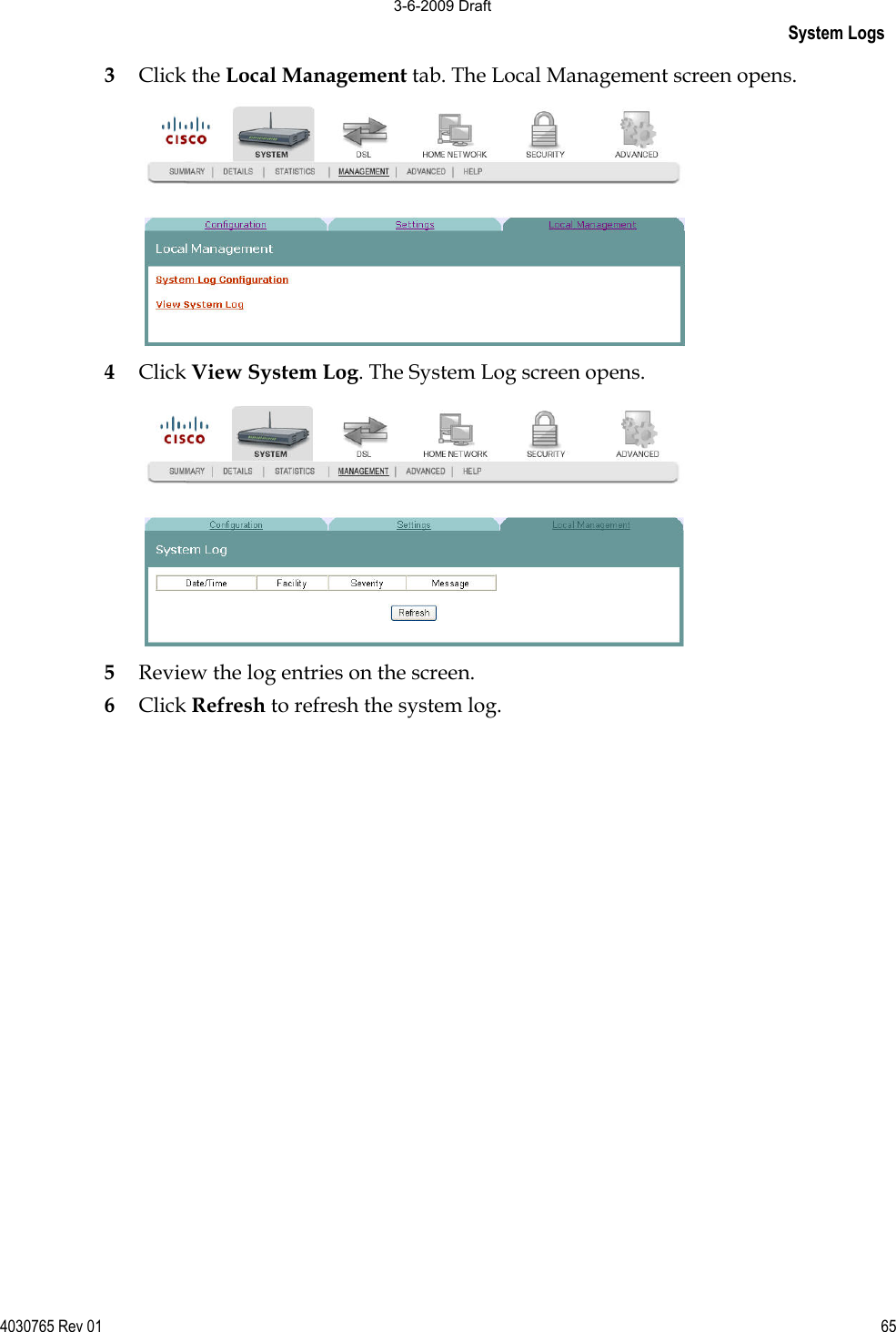
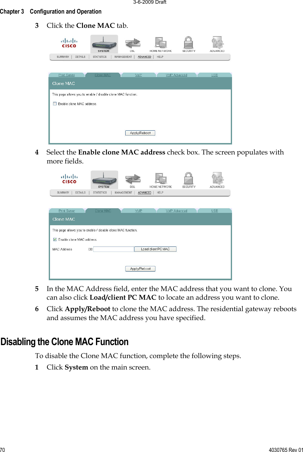


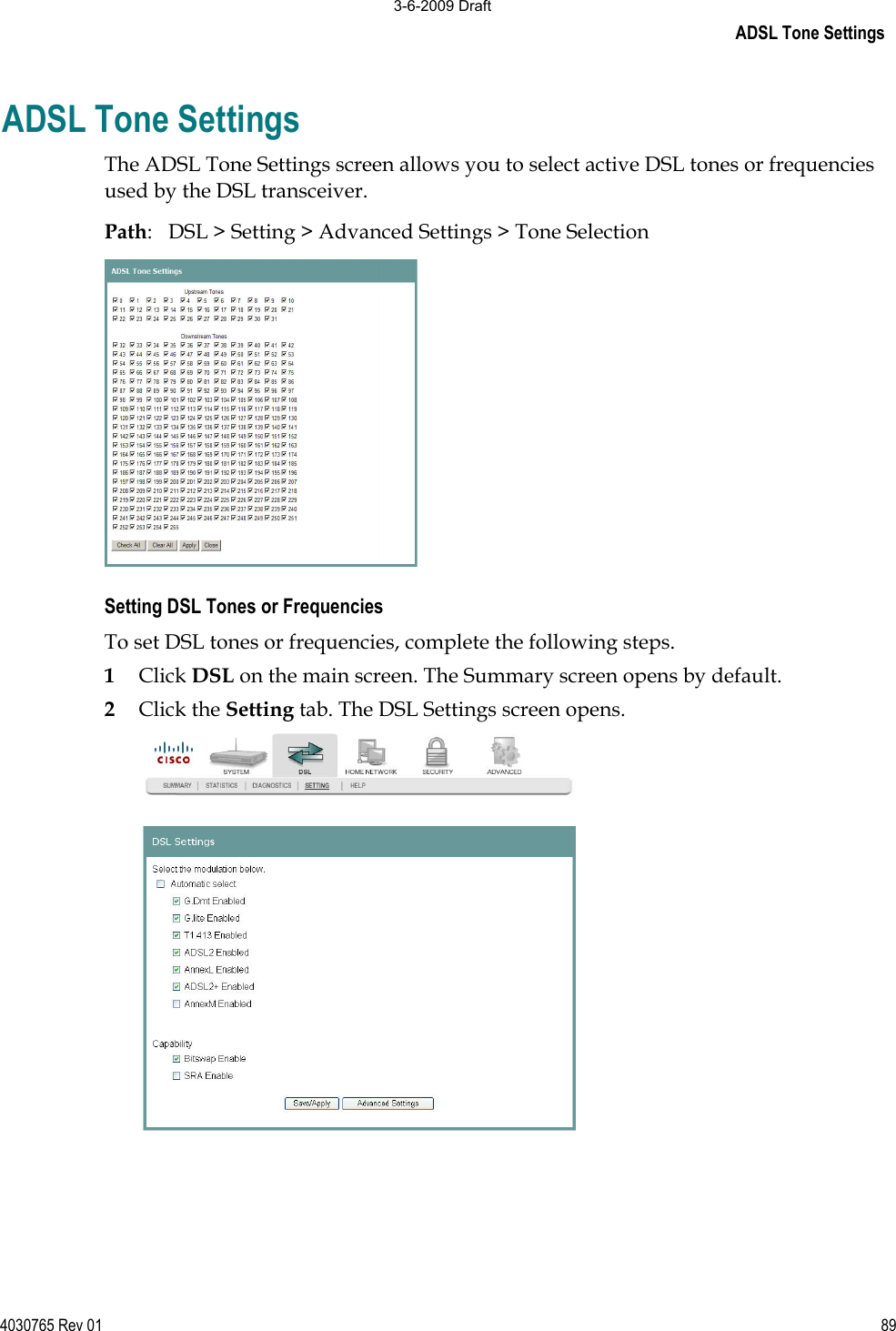
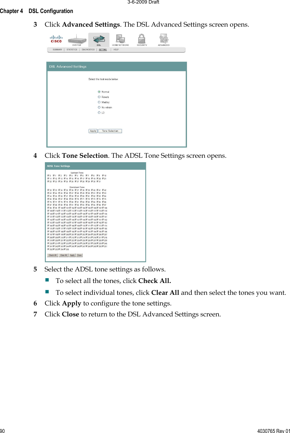
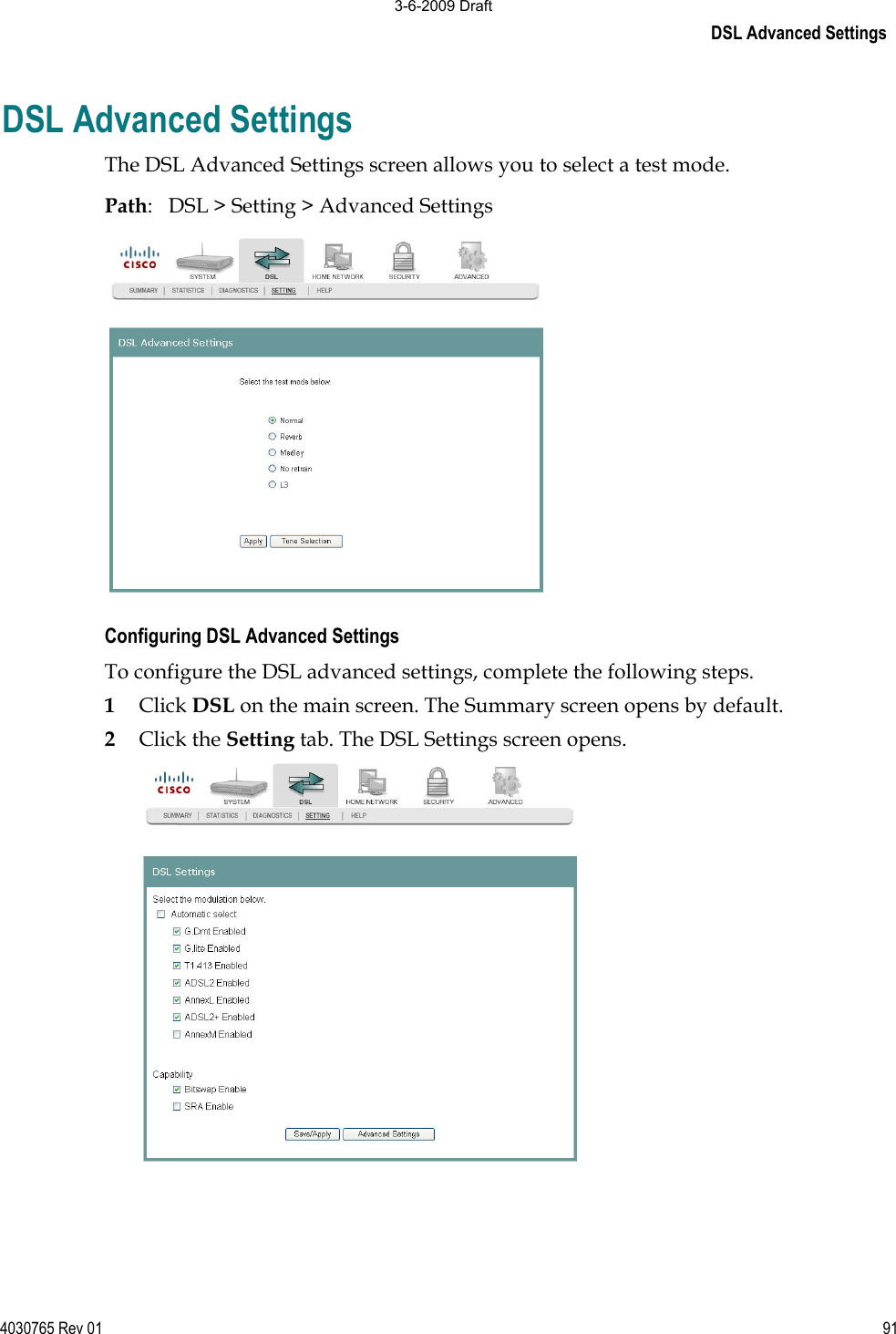
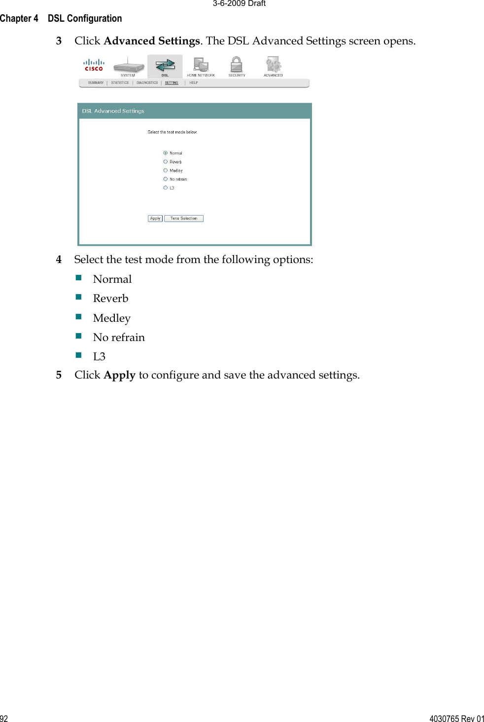
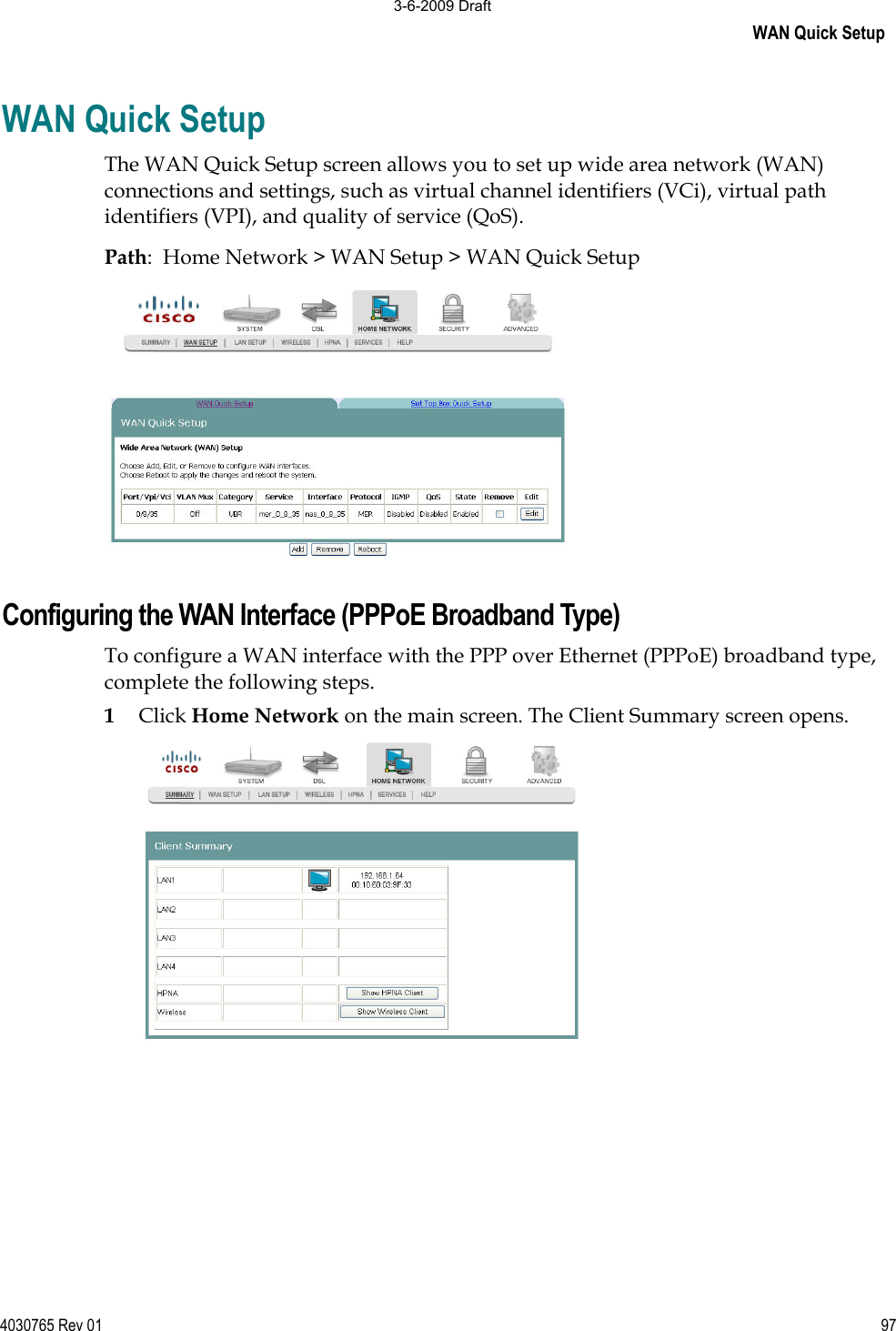
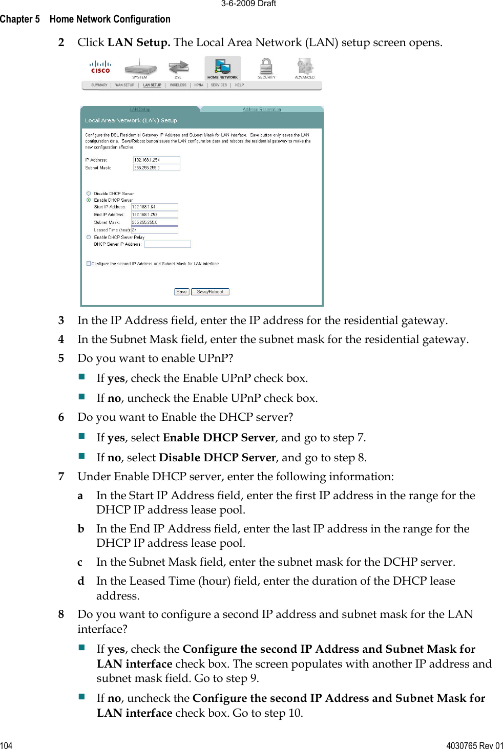
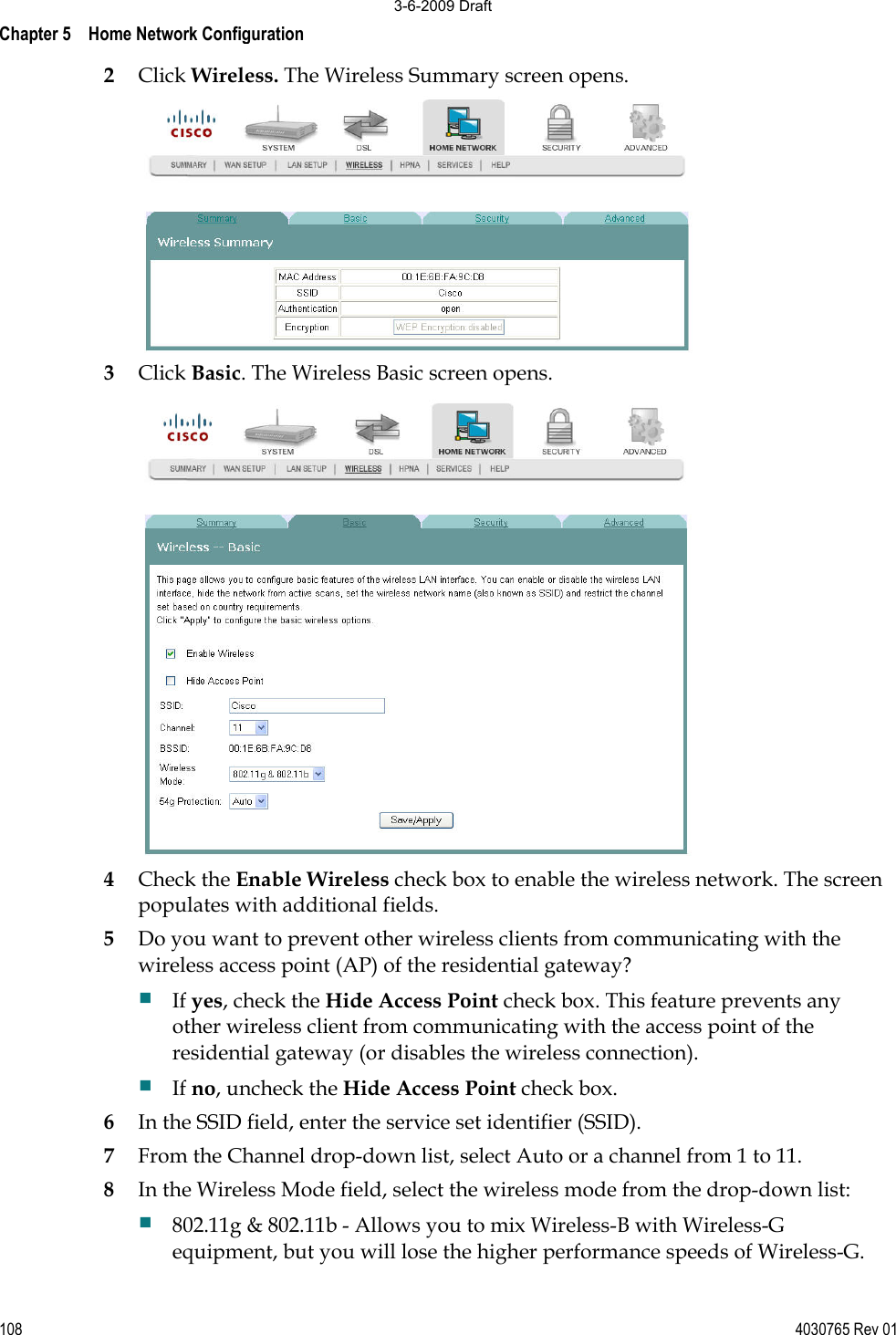
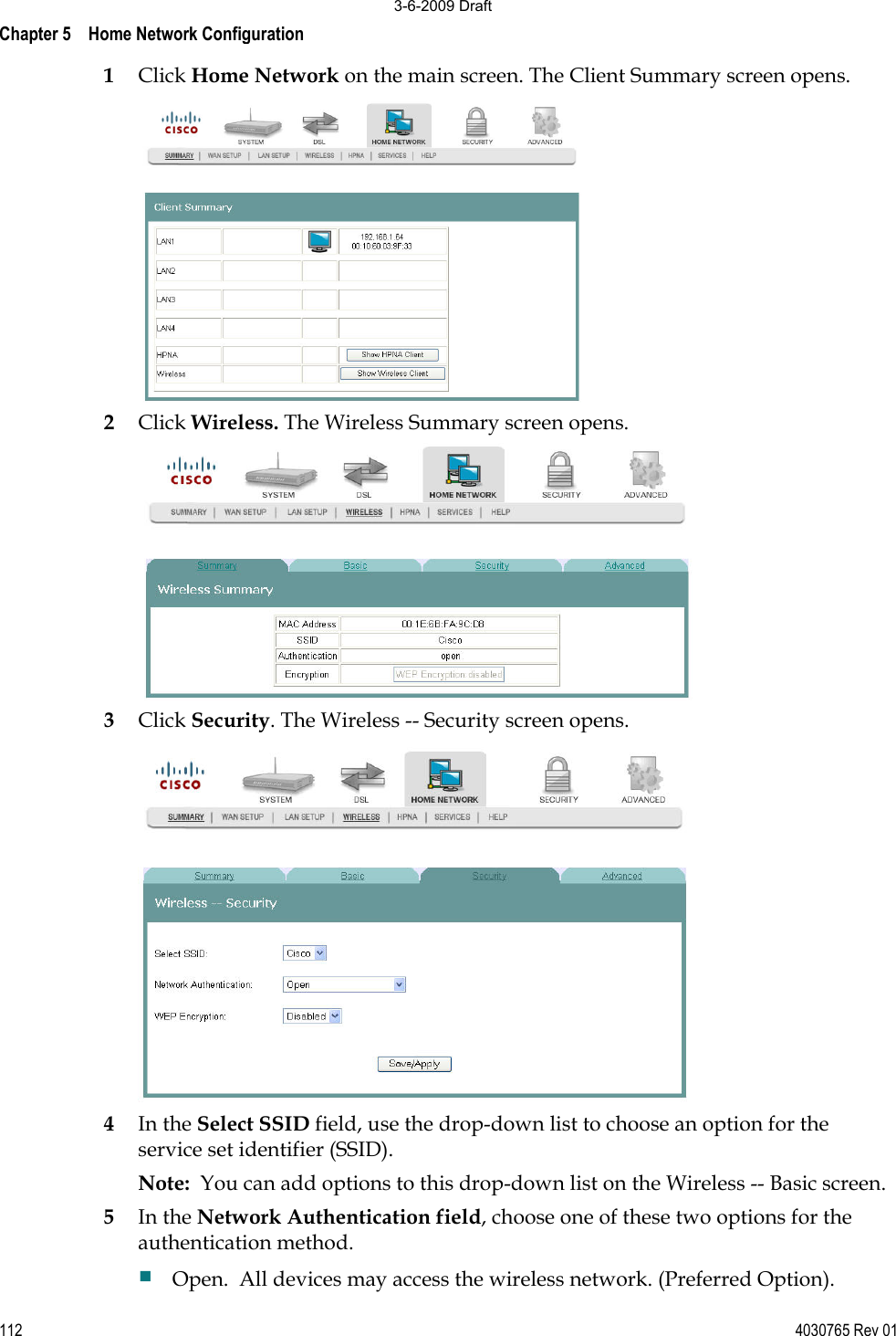
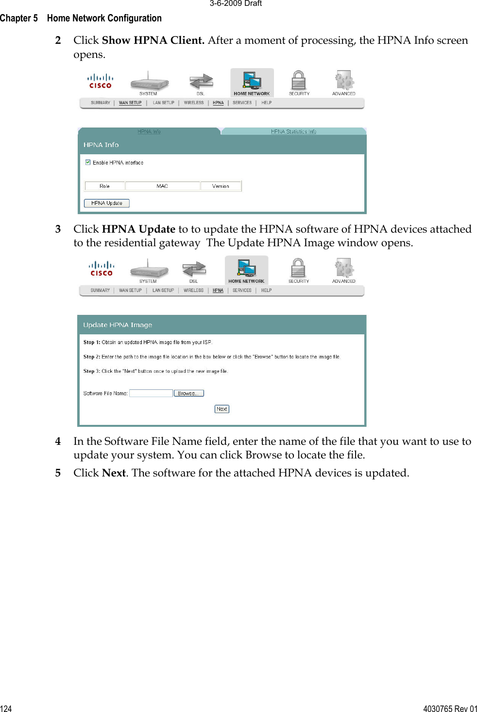
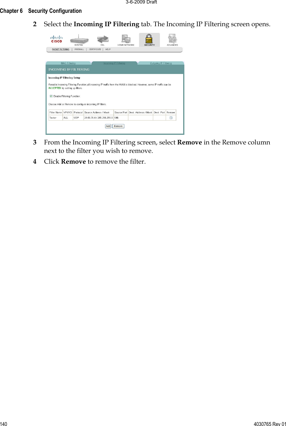
![WAN Quick Setup 4030765 Rev 01 99Configuring the WAN Interface (MER Broadband Type) To configure a WAN interface for MAC Encapsulation Routing (MER) broadband type, complete the following steps.1Click Home Network on the main screen. The Client Summary screen opens. 2Click WAN Setup. The WAN Quick Setup screen opens. Q. to reviewers: Need to click Add or Edit to see this screen. 3Click Add or Edit. <Need populated screen screen> 4In the Broadband Type field, enter DSL. 5In the DSL Mode field, select ATM. More fields populate on the screen. 6Complete the following fields on the screen as follows: Note: This configuration is an example of a specific setting for the residential gateway. Your values may differ depending upon your service provider. aIn the Broadband Connect Type field, select MAC Encapsulation Routing (MER). bIn the Encapsulation Mode field, select LLC/SNAP - Bridging. cSelect the VLAN Mux - Enable Multiple Protocols Over a Single PVC check box. dIn the VLAN ID[0-4095]: field, enter an ID for the VLAN. Values are 0-4095. eIn the VPI field, enter the virtual path identifier (VPI). Values are: 0 to 65535 fIn the VCI field, enter the virtual channel identifier (VCI). Values are: 0 to65535 gIn the the Service Category field, select UBR Without PCR. hSelect the Enable Quality of Service check box. iSelect the Obtain an IP address automatically option. jSelect the Obtain default gateway automatically option. kSelect the Obtain DNS server addresses automatically option. 3-6-2009 Draft](https://usermanual.wiki/GemTek-Technology/ADV980114G.Manual-2/User-Guide-1081643-Page-43.png)