GemTek Technology ADV980114G DDR2201 v1 ADSL2+ Residential Gateway User Manual Manual 3
Gemtek Technology Co., Ltd. DDR2201 v1 ADSL2+ Residential Gateway Manual 3
UserManual.wiki
>
GemTek Technology
>
ADV980114G User Manual
>
Manual 3
Contents
1.
Manual 1
2.
Manual 2
3.
Manual 3
Manual 3
Navigation menu
Upload a User Manual
Namespaces
Wiki Guide
HTML
PDF
Info
Views
User Manual
Discussion / Help
Navigation
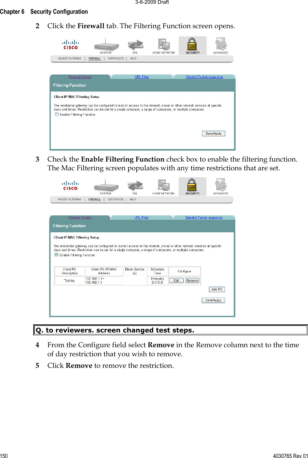
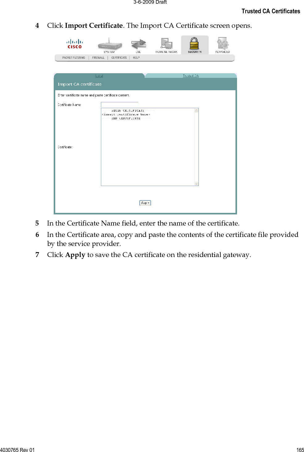


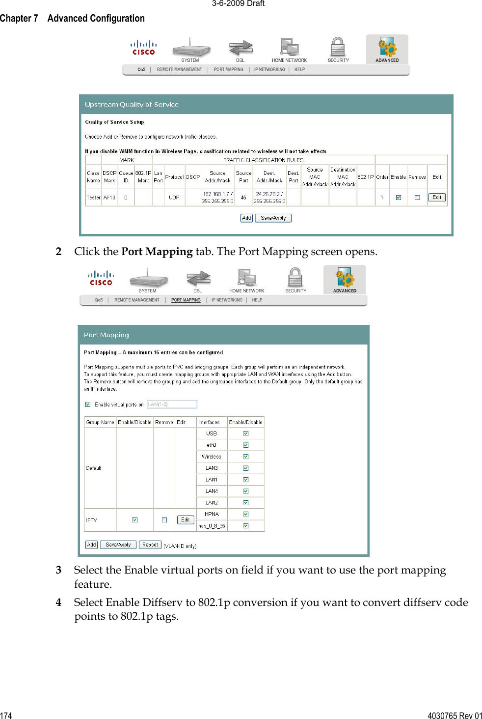
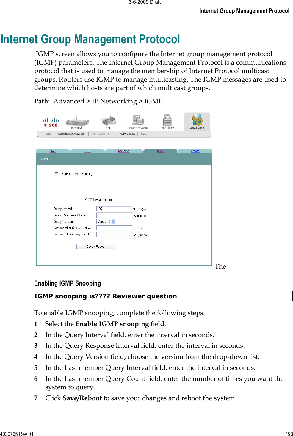
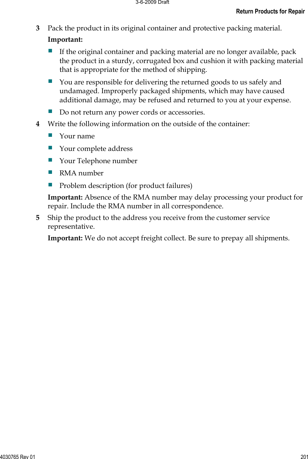
![Port Mapping 4030765 Rev 01 1755Click Add. The Port Mapping Configuration screen opens. 6In the Group Name field, enter the name of the group. The group name must be unique. For example, enter IPTV. 7For the Grouped Interfaces field, select interfaces from the Available Interfaces list and add them to the grouped interface list using the arrow buttons to create the required mapping of the ports. 8In the Automatically Add Clients With the following DHCP Vendor IDs, add the DHCP option 60 [vendor ID option] string for the devices (typically IP set-tops) attached to the residential gateway.9Click Save/Apply. 3-6-2009 Draft](https://usermanual.wiki/GemTek-Technology/ADV980114G.Manual-3/User-Guide-1081644-Page-29.png)