GemTek Technology WIXS-168 WiMAX Outdoor CPE User Manual PRO 3000 CPE Quick Installation Guide
Gemtek Technology Co., Ltd. WiMAX Outdoor CPE PRO 3000 CPE Quick Installation Guide
Contents
- 1. User manual 1
- 2. User manual 2
- 3. User manual
User manual 2
PRO 3000 CPE Quick Installation Guide
- 1 -
This Quick Installation Guide is intended for experienced installers. For more information refer to the relevant sections in the
CPEs Product Manual.
Package Content
Check that the package contains:
PRO 3000 ODU
Crossed Ethernet cable with two RJ-45 connectors for connecting the NG_VG power injector to a PC/HUB/switch.
Sealing cap
Pole mounting kit
Additional Equipment and Tools required for Installation
Indoor-to-outdoor Category 5E PoE Ethernet cable with two shielded RJ-45 connectors (can be ordered separately) and an
RJ-45 connectors crimping tool.
Mains plug adapter or termination plug (if the power plug on the supplied AC power cord does not fit local power outlets).
Sealing materials: mastic tape (Scotchfil™ Electrical Insulation Putty), Cold Shrink sealing kit.
WARNING: ONLY experienced installation professionals who are familiar with local building and safety codes and,
wherever applicable, are licensed by the appropriate government regulatory authorities should install outdoor
units and antennas. Failure to do so may void the product warranty and may expose the end user or Service
Provider to legal and financial liabilities. The manufacturer and its resellers or distributors are not liable for
injury, damage or regulation violations associated with the installation of outdoor units or antennas.
Equipment Location Guidelines
Select the optimal locations for the equipment using the following guidelines:
1. The antenna should provide a direct, or near line of sight, with the Base Station antenna. The higher the placement of the
antenna, the better the achievable link quality. The location of the ODU should enable easy access to the unit for
installation and testing.
2. The indoor equipment should be installed as close as possible to the location where the indoor-to-outdoor cable enters the
building. The location of the indoor equipment should be selected taking into account its connection to a power outlet and
the end-user’s data equipment. (The length of the IDU-to-ODU cable, together with the length of the cable connecting the
IDU to the data equipment, should not exceed 100m).
ODU Installation
Mounting the ODU
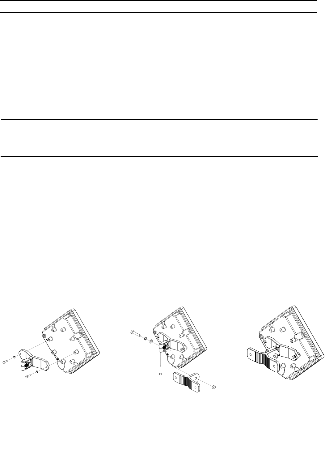
Mount the ODU unit on a 1"-4" pole using the supplied kit:
1. With the connector facing downward, attach the bracket to the two designated holes at the back of the ODU, as shown in
Figure 1. Use the two M5*16mm bolts and spring washers. (Figure 1)
2. Thread the M8*40mm bolt through a spring washer and a flat washer and then through the bracket hole. (Figure 2)
3. Thread the M5*35mm bolt through the designated hole in the bracket. (Figure 2)
4. Attach the clamp to the bracket such that the bolt is threaded through it and tighten using an M8 nut. Make sure the bracket
is secured tightly. (Figure 3)
5. Attach the ODU to a 1" -4" pole. Attach the clamp to the other side of the pole. Thread the M8*100mm bolts through both
clamp holes on either side using spring washers. Tighten the bolts using nuts and spring washers. (Figure 4)
Figure 1 Figure 2 Figure 3
ODU
M8*40mm
bolt
Bracket
Clamp
M5*35 bolt
M5*16mm
B
o
l
t
M8 nut
P/N: 215805
PRO 3000 CPE Quick Installation Guide
- 2 -
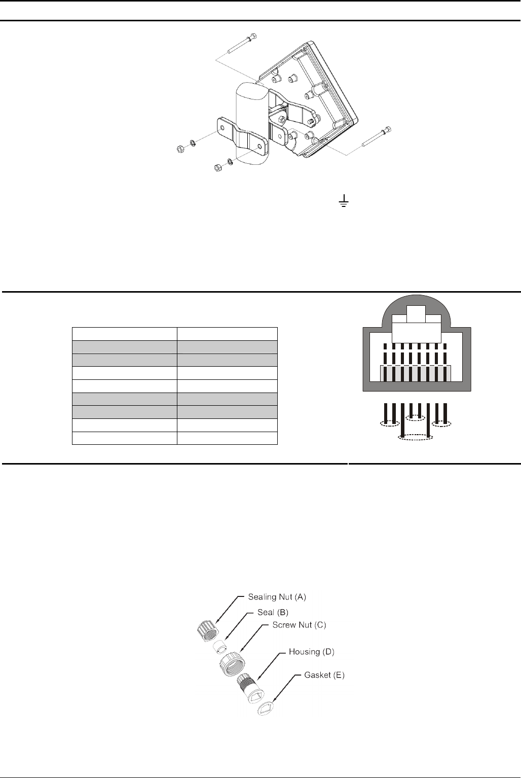
Figure 4
6. Connect a grounding cable between the Ground terminal of the ODU (marked ) and a good ground connection.
Preparing the IDU-ODU Cable
Use a crimp tool for RJ-45 connectors to prepare the wires. Insert them into the appropriate pins and use the tool to crimp the
connector. Make sure to do the following:
Remove as small a length as possible of the external jacket. Verify that the external jacket is well inside the sealing
cover when connected to the unit, to ensure good sealing.
Pull back the shield drain wire before inserting the cable into the RJ-45 connector, to ensure a good connection with
the connector's shield after crimping.
The following diagram shows the required wire pair pin-to-pin connections,
including the color codes used in cables supplied by the manufacturer.
Wire color Pin
Blue 1
Blue/white 2
Orange 3
Orange/white 6
Brown 4
Brown/white 5
Green 7
Green/white 8
12345678
1 + 2 4 + 5
7 + 8
3 + 6
P/N: 215805
Connecting and Sealing the IDU-ODU Cable
For increased weather protection, use high quality sealing material such as Scotchfil™ Electrical Insulation Putty from 3M (or
equivalent), over-wrapped with a UV resistant outdoor rated tape (e.g. Super 33+ or Super 88 vinyl Electrical Tape). To seal the
connector, use high quality cold shrink sleeves.
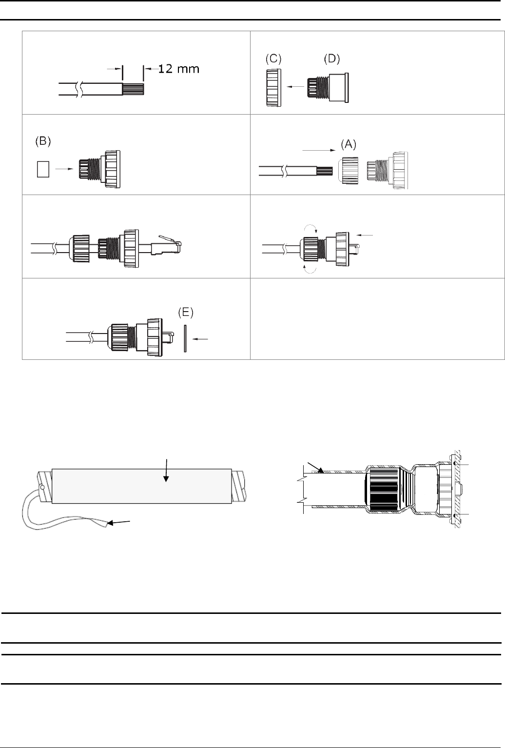
1. Cut the cold shrink sleeve to size. Take into account the size of the unit’s connector and additional 2.5 cm (0.5 in.).
2. Slide the cold shrink sleeve onto the cable before connecting the cable.
3. Follow the detailed instructions supplied with the sealing cap to assemble the sealing cap onto the cable:
Sealing Components
PRO 3000 CPE Quick Installation Guide
- 3 -
a. Strip the cable sheath. b. Insert the screw nut into the housing.
c. Insert the seal at the back end of the housing. d. Insert the cable all the way through.
e. Crimp the RJ-45 plug f. Insert the plug into the housing. Secure the sealing nut in
place.
g. Stricken the gasket on the front end of the housing. h. Secure the screw nut (C) in place.
4. Connect the Ethernet cable to the RJ-45 connector of the ODU. Make sure that the connector is completely inserted and
tightened.
5. Attach the mastic tape (Scotchfil™ Electrical Insulation Putty) and wrap it around the connector butting up against the
connector. Do not over stretch.
6. Squeeze to tighten the mastic sealer. Make sure there are no air bubbles.
7. Slide the cold shrink sleeve on top of the connector. Make sure that the sleeve covers both cable connector and unit
connector.
Figure 4 Cold Shrink Tubing
Cold Shrink Sleeve Cold Shrink Seal
Cord
8. Pull the cord slowly to shrink the sleeve.
9. Route the cable to the location selected for the indoor equipment.
10. Assemble an RJ-45 connector with a protective cover on the indoor end of the IDU-ODU cable. Refer to the pin assignment
and color codes in standard cables described above.
NG_VG Installation
WARNING: Make sure to use the PoL-PoE adapter. Failing to do so may damage the equipment.
Note: It is assumed that the installation and configuration of the PRO 3000 CPE has already been completed, and
that the NG_VG was preconfigured by the operator.
1. Connect the PoL-PoE adapter to the NG_VG WAN port.
2. Place the NG_VG on a desktop or shelf. The location should be selected taking into account the Equipment Location
Guidelines above.
3. Connect the mains power cord to the power supply. Connect one end to the 48 VDC jack on the rear panel of the NG_VG.
Connect other end to the AC mains.
P/N: 215805

PRO 3000 CPE Quick Installation Guide
- 4 -
P/N: 215805
4. Connect one end of the straight Ethernet cable (8P8C) to the PoL-PoE adapter.
5. Connect the other end to the LAN port of the PRO 3000 CPE.
For more information refer to the NG_VG Quick Installation Guide.
Basic Configuration
Using the Web Configuration Server
1. Use the Web Configuration Server to configure the basic parameters.
2. Connect a PC/Notebook to the LAN port of the NG_VG, using the supplied Ethernet cable.
3. Ensure that the NG_VG has a WAN Data Service configured with NAT enabled and with all NG_VG LAN ports grouped to it
(Refer to the NG-VG manual for details).
4. By default, the CPE has a DHCP server enabled. In this case, ensure that the NG_VG WAN Data Service is configured to
receive its IP by DHCP from the CPE.
If the DHCP server of the CPE is disabled, for the WAN Data Service on the NG_VG you can manually set a static IP
address, netmask, and gateway according to your CPE model (refer to the table below):
Table 1: Connectivity Parameters
Model Name Basic Connectivity Parameters
4M-K2-CPE-Si-1D-2.5
4M-CPE3000-PRO-1D-2.3
4M-K2-CPE-PRO-ODU-1D-2.5
4M-K2-CPE-PRO-ODU-1D-3.3
4M-CPE3000-PRO-1D-3.6
IP address: 192.168.254.x, 1 < x < 253, excluding 251
Netmask: 255.255.255.0
Gateway: 192.168.254.251
4M-CPE3000-PRO-1D 3.4-3.7 IP address: 192.168.209.x, 2 < x < 253
Netmask: 255.255.255.0
Gateway: 192.168.209.1
5. From a PC connected to the NG_VG open a web browser, and connect to http:// 192.168.254.251/. The Login page is
displayed. Enter the user name and password and click Login.
6. Configure the parameters, as needed.
7. Reset the unit to apply the changes.
Using the Auto-configuration Tool
1. Connect a PC/Notebook to the LAN port of the NG_VG, using the supplied Ethernet cable.
2. Ensure that the NG_VG has a WAN Data Service configured with NAT enabled and with all NG_VG LAN ports grouped to it
(Refer to the NG_VG manual for details). Also, ensure that the NG_VG WAN Data Service is configured to receive its IP by
DHCP from the CPE.
3. Switch on the CPE and wait until the NG_VG Data service connection receives an IP.
4. From the CDROM supplied with the unit, run the CPE Auto Configuration Tool: CPEAutoConfigTool.exe; The Installation
Setup Wizard window is displayed.
5. Click Next to continue; The Choose Your ISP window is displayed.
6. Choose the ISP (Internet Service Provider) ConfigFile from the list and click Next. The Ready To Install window is
displayed.
7. Click Install. The tool starts the auto-configuration process of the CPE settings. It will change default configuration by using
the *.CONF file, and then run “reset to factory default” by using default configuration in the file.
8. When the installation is complete, click Finish. The CPE is now configured with the parameters from the ConfigFile.
Aligning the ODU's Antenna
1. Point the ODU toward the general direction of the serving BTS.
2. Verify that the unit is synchronized with a BTS. If the SU is not synchronized with a BTS, ensure that all parameters are
configured properly. If the unit is still not synchronized with a BTS, improve the quality of the link by changing the direction
of the ODU or by placing the ODU at a higher or in an alternate location.
3. Ensure that the front of the ODU is always facing the location of the BTS. However, in certain conditions, such as when the
line of site to the BTS is hampered, better reception may be achieved using a reflected signal. In this case, the ODU is not
always directed toward the BTS.
4. Secure the unit firmly to the pole.
Verifying Proper Operation
1. Verify data connectivity by sending a ping command to the BTS or by connecting to the Internet.
2. To verify proper operation of the SU, examine the LED indicators on the NG_VG:

PRO 3000 CPE Quick Installation Guide
- 5 -
Table 2: NG_VG LEDs
Name Description Functionality
WAN WAN Port Status
Indication
Off: Wired interface not established (Ethernet connection not detected).
Blinking: Traffic is passing through.
On: Wired interface established (Ethernet connection detected).
Radio Frequency Interference Statement
This equipment has been tested and found to comply with RSS-197 and RSS-192 of the Industry Canada Rules (for 3.x GHz
bandwidth) and the limits for a class B digital device, pursuant to ETSI EN 301 489-1 and Part 15 of the FCC Rules. These limits
are designed to provide reasonable protection against harmful interference when the equipment is operated in a residential
environment notwithstanding use in commercial, business and industrial environments. This equipment generates, uses, and
can radiate radio frequency energy and, if not installed and used in accordance with the instruction manual, may cause harmful
interference to radio communications.
Radiation Hazard Warning
To comply with FCC RF exposure requirements in Section 1.1307 and 2.1091 of FCC Rules, the antenna used for this
transmitter must be kept at a separation distance of at least 50 cm from all persons and must not be co-located or operating in
conjunction with any other antenna or transmitter.
R&TTE Compliance Statement
This equipment complies with the appropriate essential requirements of Article 3 of the R&TTE Directive 1999/5/EC.
Disposal of Electronic and Electrical Waste
Disposal of Electronic and Electrical Waste
Pursuant to the WEEE EU Directive electronic and electrical waste must not be disposed of with unsorted waste. Please
contact your local recycling authority for disposal of this product.
P/N: 215805