GemTek Technology WSETH Wireless Space User Manual Manual Part 3
Gemtek Technology Co., Ltd. Wireless Space Manual Part 3
Contents
- 1. Manual Part 1
- 2. Manual Part 2
- 3. Manual Part 3
- 4. Manual Part 4
Manual Part 3
LaCie Wireless Space • DESIGN BY NEIL POULTON Beyond Basic Install: Setup Wizard
User Manual page 73
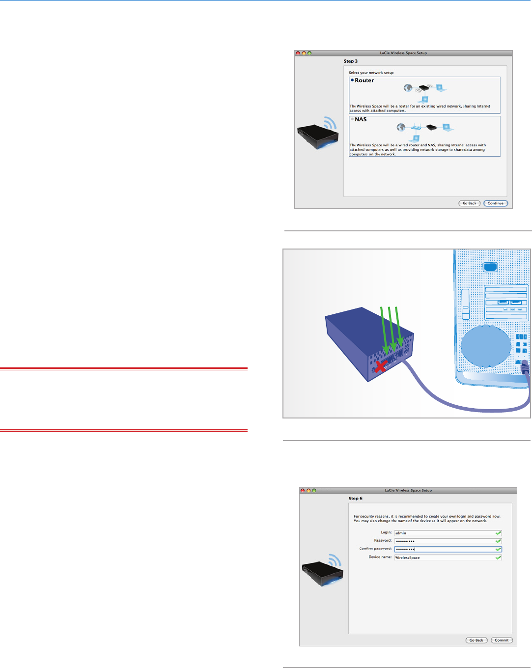
5. Select Router. Click Continue. (Fig. 116)
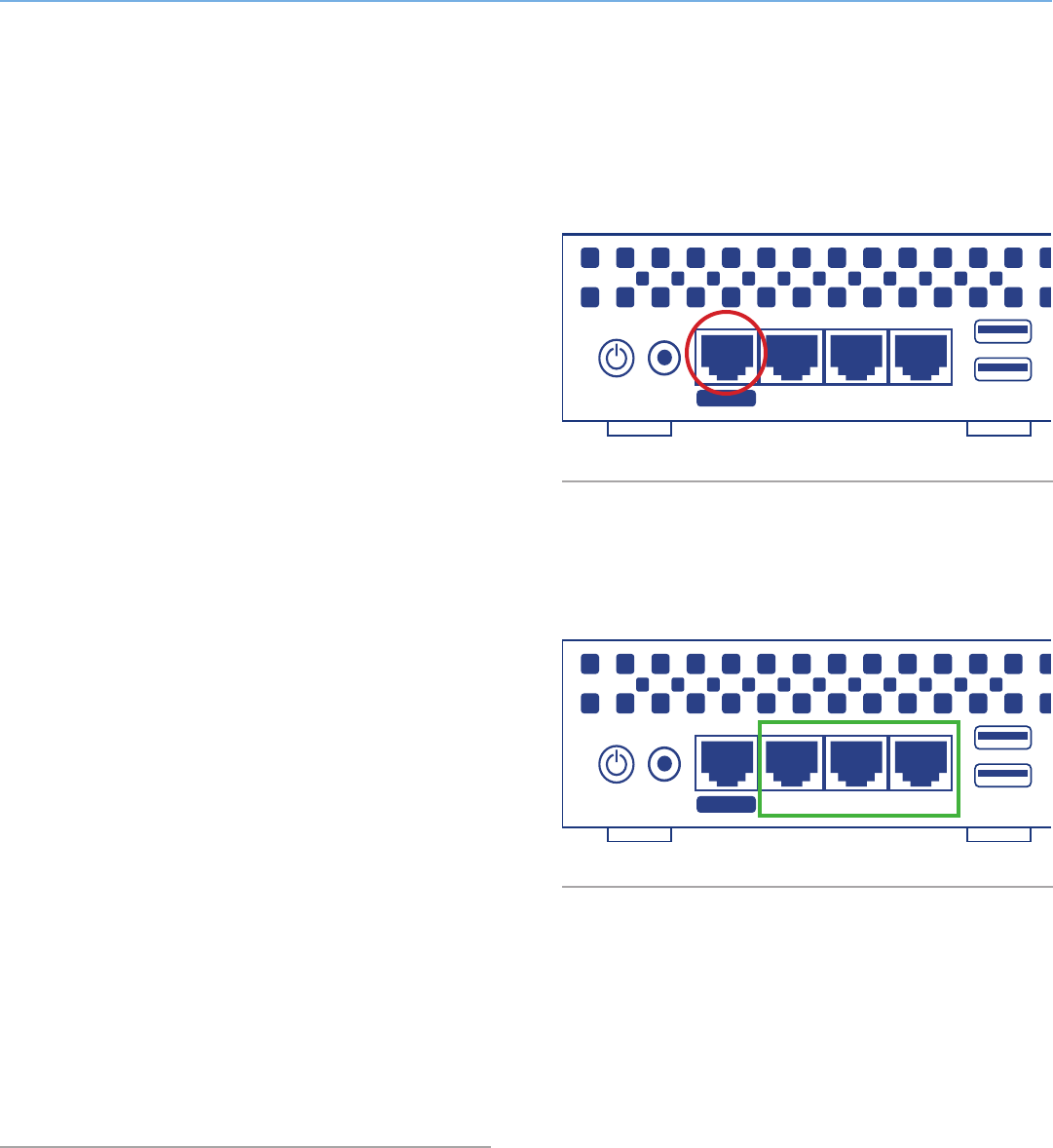
6. You will be prompted to connect your computer to the Wireless
Space. Please use one of the three ports marked LAN1, LAN2,
or LAN3 on the back of the Wireless Space (1.4.2. Rear View).
DO NOT connect the cable to the port named INTERNET (Fig.
117). LaCie recommends a Gigabit Ethernet cable for optimal
performance (1.6. Gigabit Ethernet Cables And Connectors).
7. Once the Wireless Space has been connected to the computer,
click Continue.
8. The Setup will search for your Wireless Space. Move to the next
step if the device is found. If not, please reinsert the Ethernet
connections on the Wireless Space and the computer before
trying again.
9. You must select and confirm a password that contains at least
eight alphanumeric characters (Fig. 118). While not mandatory,
LaCie recommends that you change the Login and Device name
as well. Make certain to note your entries for future reference.
10. Click Commit when you are ready for the Wireless Space Setup
to configure the device.
11. The Wireless Space will reboot for the changes to take effect. If
you received an error, please try again.
IMPORTANT INFO: Frequent errors during the Setup may occur
if too much time is taken to click Continue or Commit. If you experi-
ence such errors, please consider your responses before starting the
Setup Wizard.
12. Once the Wireless Space has restarted, the device light will turn
solid green, indicating that the wireless access point has not
been enabled.
continued on the next page>>
Fig. 116
Fig. 117
Fig. 118
Attach the computer to
LAN1, LAN2, or LAN3.
Do not attach the com-
puter to the INTERNET
port for the Setup.
LaCie Wireless Space • DESIGN BY NEIL POULTON Beyond Basic Install: Setup Wizard
User Manual page 74
13. The default router IP address for the Wireless Space is now
192.168.1.1. If your router or Internet provider is prepared to
add the Wireless Space to the network, move to step 14. If you
are unsure or must change the IP address:
✦You may maintain the Ethernet connection between your com-
puter and the Wireless Space. However, do not connect the
Wireless Space to the server, router, or Internet provider be-
fore considering DHCP server conflicts.
✦DHCP Server Conflicts: Your network most likely receives IP
addresses via a router, server, or Internet provider. The de-
vice that manages the IP addresses is generally referred to as
a DHCP server. The Wireless Space, when configured as a
router, also assigns IP addresses to all devices using its LAN
Ethernet ports. Since it could affect the performance for all
devices, a network should not have two DHCP servers at-
tempting to assign IP addresses. Such a conflict may occur
if the Ethernet cable between the router, server, or Internet
provider and the Wireless Space is attached to one of the LAN
ports. When using a router configuration, the Ethernet cable
between the router, server, or Internet provider and the Wire-
less Space should connect to the INTERNET port on the back
of the Wireless Space (Fig. 119). The WAN interface default
setting for the Wireless Space is DHCP client, which means
that your router, server, or Internet provider should accept it
without a conflict. However, please see the user manual of
your router, server, or Internet provider for further details on
how it manages devices on the network. If it is not a DHCP
server, you may have to assign a static IP address to the Wire-
less Space before attaching it to the network. See 4.6. INTER-
NET Port: NAS+Router for more information on the INTERNET
port and 4.5.3. Dashboard: Network WAN to learn more on
the Wireless Space WAN Interface and how to assign a static
IP address. For an example on how to avoid IP conflicts, see
4.5.4.1. Avoiding Router IP Address Conflicts: Example
✦Devices such as computers and gaming systems use the LAN
ports (Fig. 120) to join the Wireless Space network. LaCie rec-
ommends a Gigabit Ethernet cable for optimal performance
(1.6. Gigabit Ethernet Cables And Connectors).
14. Install LaCie Network Assistant (see 3.4. LaCie Network Assis-
tant).
15. Connect the Wireless Space to the router, switch, or Internet
provider via the included Gigabit Ethernet cable. Please use the
port marked INTERNET on the back of the Wireless Space (Fig.
119 & 1.4.2. Rear View).
USBLAN1 LAN2 LAN3
INTERNET
USBLAN1 LAN2 LAN3
INTERNET
Fig. 119
Fig. 120

LaCie Wireless Space • DESIGN BY NEIL POULTON Beyond Basic Install: Setup Wizard
User Manual page 75
4.4. Configuration 5: Router
Wireless Access Point
IMPORTANT INFO: DO NOT attempt to access the Wireless
Space via the web-enabled Dashboard (see 3.6.1. Dashboard: Ac-
cessing) before running the Setup Wizard. During the initial con-
figuration, the Setup Wizard must find the Wireless Space on the
network. If the Dashboard has made contact with the device, the
Setup Wizard will not run since it believes the choice of configuration
has already been made. This could be problematic when attaching
the Wireless Space to a network with a router, server, or Internet
provider that assigns IP addresses using DHCP. Most DHCP serv-
ers or devices use the same default settings as the Wireless Space
when it is set to a Router configuration, which can create IP address
conflicts on a network.
Please see 2. What is the best configuration for my network? before
preparing your Wireless Space.
4.4.1. Wireless Space Setup Wizard
Preparing for the setup:
✦Do not connect the Wireless Space to your router, switch, or
Internet provider via Ethernet.
✦Quit the applications running on your computer, especially
those having to do with Internet connectivity (web browsers,
email, etc.)
✦If your computer is connected to the router, switch, or Inter-
net provider via Ethernet, please disconnect the end from the
router, switch, or Internet provider.
✦LaCie recommends that you disconnect from Wi-Fi networks
while running the Wireless Space Setup Wizard. You may re-
connect to a Wi-Fi once the setup is finished.
1. Connect the power cable to the Wireless Space (see 3.1. Con-
nect the Power Supply) and turn the device on (1.5. Power But-
ton Functions). In most instances, the light will become solid
green and turn red during the setup.
2. Run the Utilities CD from the computer’s optical disk drive.
Launch the Wireless Space Setup when prompted. DO NOT in-
stall LaCie Network Assistant before running the Wireless Space
Setup.
3. Choose your language then select OK. After reading the wel-
come screen text, click Continue.
continued on the next page>>
LaCie Wireless Space • DESIGN BY NEIL POULTON Beyond Basic Install: Setup Wizard
User Manual page 76
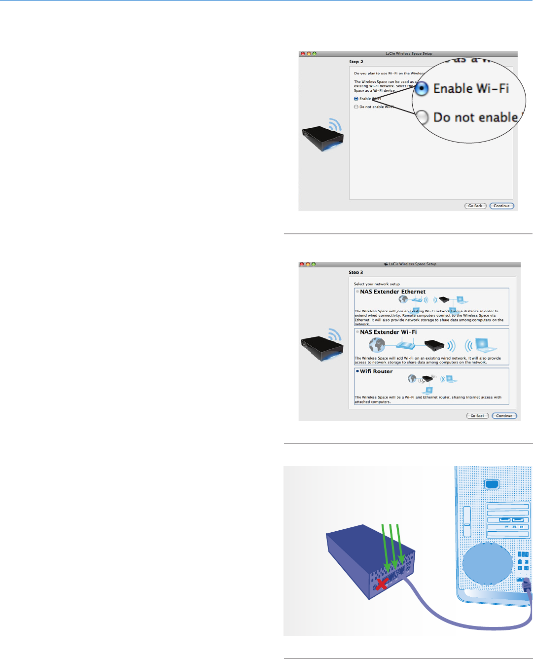
4. Select Enable Wi-Fi. Click Continue. (Fig. 121)
5. Select Wifi Router. Click Continue. (Fig. 122)
6. You will be prompted to connect your computer to the Wireless
Space. Please use one of the three ports marked LAN1, LAN2,
or LAN3 on the back of the Wireless Space (1.4.2. Rear View).
DO NOT connect the cable to the port named INTERNET (Fig.
123). LaCie recommends a Gigabit Ethernet cable for optimal
performance (1.6. Gigabit Ethernet Cables And Connectors).
7. Once the Wireless Space has been connected to the computer,
click Continue.
8. The Setup will search for your Wireless Space. Move to the next
step if the device is found. If not, please reinsert the Ethernet
connections on the Wireless Space and the computer before
trying again.
continued on the next page>
Fig. 121
Fig. 122
Fig. 123
Attach the computer to
LAN1, LAN2, or LAN3.
Do not attach the com-
puter to the INTERNET
port for the Setup.
LaCie Wireless Space • DESIGN BY NEIL POULTON Beyond Basic Install: Setup Wizard
User Manual page 77
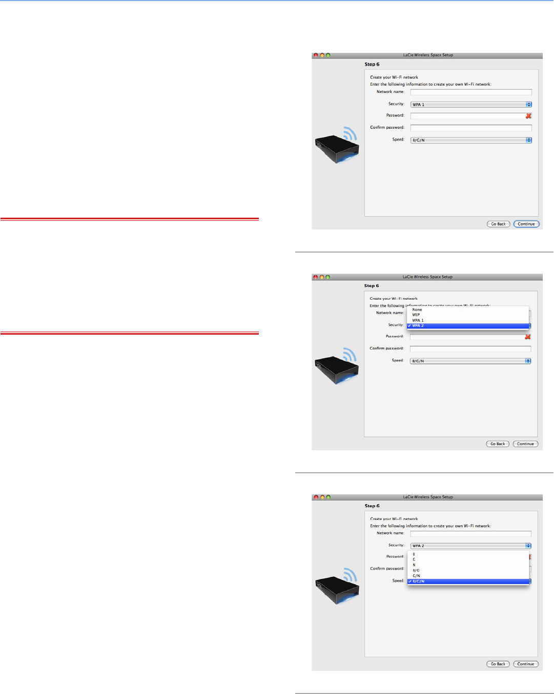
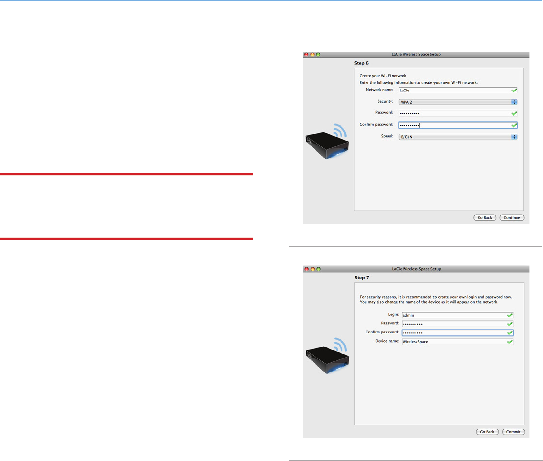
9. You must provide the following information to create a Wi-Fi
access point (Fig. 124):
✦Network name
✦Security protocol (Fig. 125)
✦Password
✦Speed (Fig. 126)
✦See 4.1. Before the Installation for further information on how
to fill out each field.
✦Make certain to write down all the information so that you may
use it when joining the Wireless Space Wi-Fi network from a
wireless device.
IMPORTANT INFO: LaCie strongly recommends that all Wireless
Space clients secure their Wi-Fi networks. For this reason, the Setup
Wizard offers three levels of security and password protection when
configuring the Wi-Fi access point. Please note that you may adjust
these settings in the Dashboard administration tool after the installa-
tion. While the Dashboard and the Setup offer “None” as a security
option, we urge all users to consider the risks to their home networks
as well as potential drains on their wireless bandwidth.
continued on the next page>
Fig. 124
Fig. 125
Fig. 126
LaCie Wireless Space • DESIGN BY NEIL POULTON Beyond Basic Install: Setup Wizard
User Manual page 78
10. Click Continue when all the fields are filled in (example, Fig.
127).
11. You must select and confirm a password that contains at least
eight alphanumeric characters (Fig. 128). While not mandatory,
LaCie recommends that you change the Login and Device name
as well. Make certain to note your entries for future reference.
12. Click Commit when you are ready for the Wireless Space Setup
to configure the device.
IMPORTANT INFO: Frequent errors during the Setup may occur
if too much time is taken to click Continue or Commit. If you experi-
ence such errors, please consider your responses before starting the
Setup Wizard.
13. Once the Wireless Space has restarted, the device light will turn
solid blue, indicating that the wireless access point has been
enabled.
continued on the next page>>
Fig. 127
Fig. 128
LaCie Wireless Space • DESIGN BY NEIL POULTON Beyond Basic Install: Setup Wizard
User Manual page 79
14. The default router IP address for the Wireless Space is now
192.168.1.1. If your router or Internet provider is prepared to
add the Wireless Space to the network, move on to step 15. If
you are unsure or must change the IP address:
✦You may maintain the Ethernet connection between your com-
puter and the Wireless Space. However, do not connect the
Wireless Space to the server, router, or Internet provider be-
fore considering DHCP sever conflicts.
✦DHCP Server Conflicts: Your network most likely receives IP
addresses via a router, server, or Internet provider. The de-
vice that manages the IP addresses is generally referred to as
a DHCP server. The Wireless Space, when configured as a
router, also assigns IP addresses to all devices using its LAN
Ethernet ports and WLAN (wireless land area network; devices
that connect via the Wi-Fi access point). Since it could affect
the performance for all devices, a network should not have
two DHCP servers attempting to assign IP addresses. Such a
conflict may occur if the Ethernet cable between the router,
server, or Internet provider and the Wireless Space is attached
to one of the LAN ports. When using a router configuration,
the Ethernet cable between the router, server, or Internet pro-
vider and the Wireless Space should connect to the INTERNET
port (Fig. 129) on the back of the Wireless Space. The WAN
interface default setting for the Wireless Space is DHCP cli-
ent, which means that your router, server, or Internet provider
should accept it without a conflict. However, please see the
user manual of your router, server, or Internet provider for
further details on how it manages devices on the network. If it
is not a DHCP server, you may have to assign a static IP ad-
dress to the Wireless Space before attaching it to the network.
See 4.6. INTERNET Port: NAS+Router for more information
on the INTERNET port and 4.5.3. Dashboard: Network WAN
to learn more on the Wireless Space WAN Interface and how
to assign a static IP address. For an example on how to avoid
IP conflicts, see 4.5.4.1. Avoiding Router IP Address Conflicts:
Example
15. Install LaCie Network Assistant (see 3.4. LaCie Network Assis-
tant).
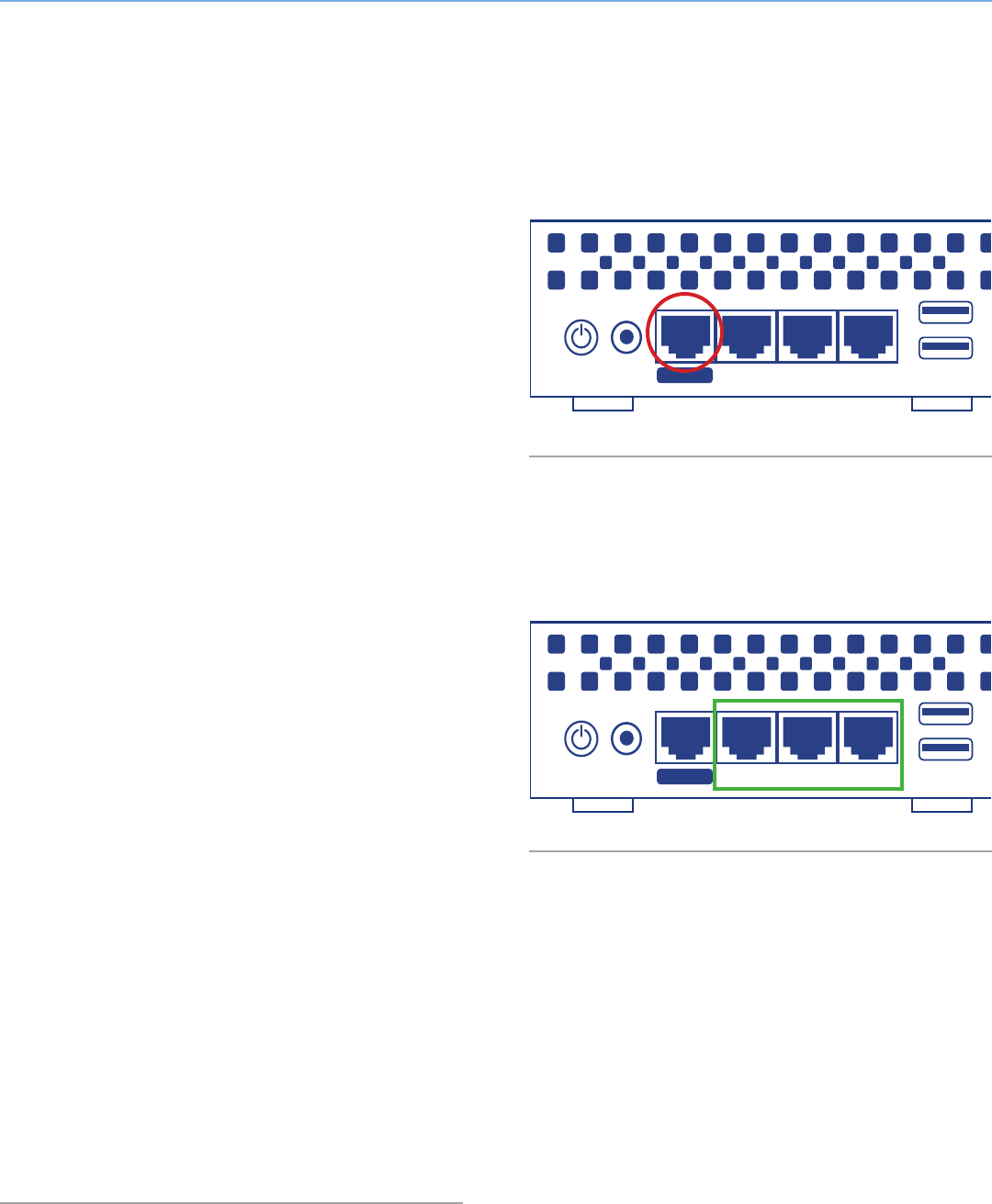
16. Connect the Wireless Space to the router, switch, or Internet
provider via the included Gigabit Ethernet cable. Please use the
port marked INTERNET on the back of the Wireless Space (Fig.
129 & 1.4.2. Rear View). Other devices on your network, such
as computers or gaming systems, may use the available LAN
ports (Fig. 130 & 1.4.2. Rear View) and/or the wireless access
point. LaCie recommends a Gigabit Ethernet cable for optimal
performance (1.6. Gigabit Ethernet Cables And Connectors).
17. Join the Wireless Space Wi-Fi network from a wireless device
using the information (Wi-Fi name, security, and password) pro-
vided during the Setup.
Fig. 129
Fig. 130
USBLAN1 LAN2 LAN3
INTERNET
USBLAN1 LAN2 LAN3
INTERNET

LaCie Wireless Space • DESIGN BY NEIL POULTON Administering the LaCie Wireless Space: Beyond Basic
User Manual page 80
4.5. Administering Your LaCie
Wireless Space - Beyond Basic
The Dashboard is a browser-based tool for administering your Wire-
less Space. To update the settings or browse files, type the Wire-
less Space’s IP address or machine name in your browser address
bar (3.4.2. Connect to the LaCie Wireless Space Dashboard directly
from the browser). LaCie Network Assistant also offers an easy link to
launch the Dashboard (3.4.1. Connect to the LaCie Wireless Space
Dashboard using LaCie Network Assistant).
This section will cover the Dashboard operations for the Beyond
Basic configurations:
NAS Ethernet - Wireless Access Point
NAS Router - Wired Only
NAS Router - Wireless Access Point
For complete information on the core Dashboard features that ap-
ply to Basic and Beyond Basic configurations, see 3.6. Administer-
ing Your LaCie Wireless Space. Beyond Basic management features
added with each configuration are listed below:
4.5.1. Dashboard: Wireless AP
4.5.2. Dashboard: Router Pages
4.5.3. Dashboard: Network WAN
4.5.4. Dashboard: Network LAN
4.5.5. Dashboard: Firewall
IMPORTANT INFO: In many instances, the Dashboard will close
whenever a setting is changed. Please wait one to two minutes for
the Dashboard to be available again.
LaCie Wireless Space • DESIGN BY NEIL POULTON Administering the LaCie Wireless Space: Beyond Basic
User Manual page 81
4.5.1. Dashboard: Wireless AP
The widget for Wireless AP will appear with Beyond Basic configura-
tions NAS Ethernet - Wireless Access Point and NAS Router - Wire-
less Access Point. Additionally, the light will remain blue during stan-
dard operation (see 1.8. Light Behavior).
The Dashboard welcome page for NAS Ethernet - Wireless Access
Point is pictured in Fig. 131:
a. Click on the name of the page to view all of the Wi-Fi access
point settings
b. The widget displays the basic Wi-Fi access point settings
c. The Mode widget indicates the current configuration
The Wireless AP page has four tabs that provide detailed informa-
tion on the Wireless Space Wi-Fi. It is a great resource to confirm
settings or to make changes.
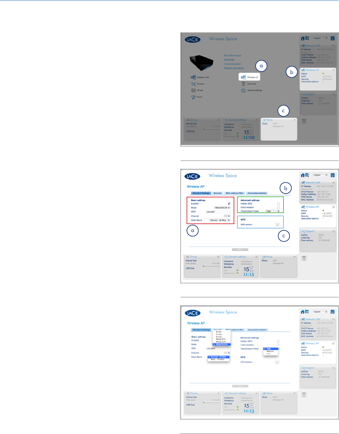
4.5.1.1. Wireless AP - Standard Settings
The first tab is Standard Settings (Fig. 132), which is broken into
three categories:
a. Basic settings
✦Enabled - This box will be checked by default with a Wi-Fi
network. Deselect the check box to turn the Wi-Fi off. When
turned off, the Dashboard will close and the light will turn
green.
✦Mode, Channel, and Radio Band - Pulldown menus (Fig. 133)
to change the speed, channel, or band of the Wi-Fi. Make
adjustments based upon the needs of the devices (speed or
802.11b/g/n compatibility) on the Wi-Fi network and the
area (i.e. a different channel if the default is creating or expe-
riencing interference).
✦SSID - The name given to the Wi-Fi for devices to recognize
and join.
b. Advanced settings
✦Hidden SSID - Disabled as a default, this feature allows you to
keep the SSID hidden from public viewing. It is an extra layer
of security for those who prefer to keep the Wireless Space
Wi-Fi unknown to others.
✦Client isolation - Disabled as a default, this feature prevents
communication between each device connected to the Wi-Fi.
✦Transmission Power - High by default, a smaller range may be
selected if desired (Fig. 133).
c. WPS - Clicking on the WPS icon allows other WPS devices to
join the Wireless Space Wi-Fi. It offers the same function as
physically pushing the WPS button on the face of the device.
continued on the next page>>
Fig. 131
Fig. 132
Fig. 133
LaCie Wireless Space • DESIGN BY NEIL POULTON Administering the LaCie Wireless Space: Beyond Basic
User Manual page 82
TECHNICAL INFO: It is normal for the Dashboard to close when
making changes to the settings. Please be patient when attempting
to reconnect as the Wireless Space updates the settings. With certain
adjustments, such as turning Wi-Fi off or on, the Wireless Space IP
address may change as well. If the Dashboard does not load in your
browser, open LaCie Network Assistant to see if the IP address has
changed. You may have to refresh LaCie Network Assistant by quit-
ting and restarting the program.
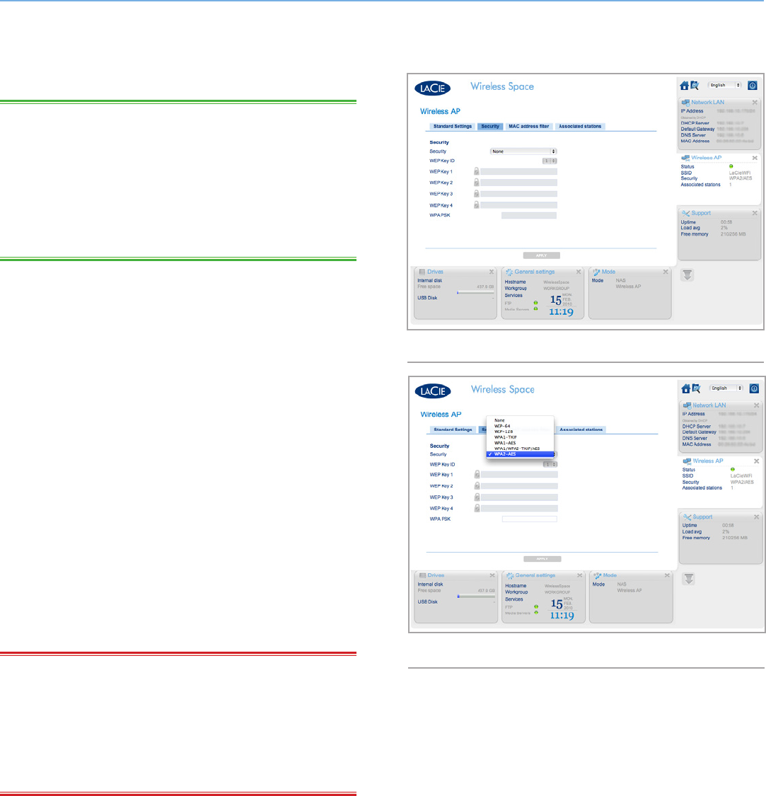
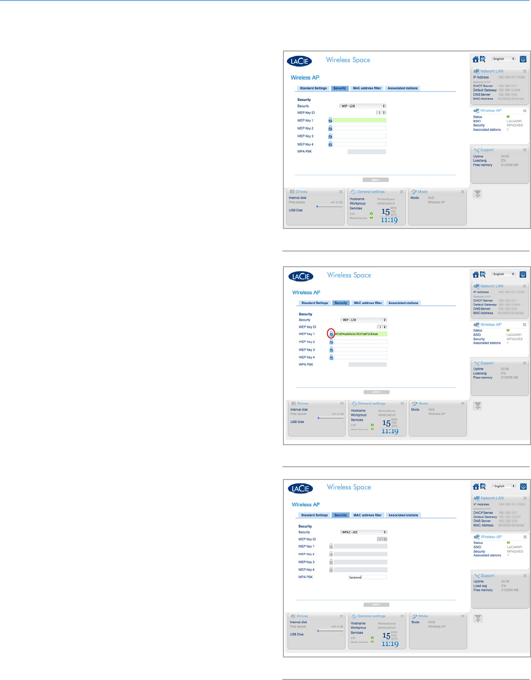
4.5.1.2. Wireless AP - Security
This tab reveals the security settings created in the Setup for Wi-Fi
access point configurations. If a new access point is being created,
the fields on the page will be blank (Fig. 134). When creating a
new wireless network or changing the security, please consider the
following:
✦What type of security do you want to use? The Wireless Space
offers WEP, WPA1, and WPA2. You may also choose to have
no security but that would leave your Wi-Fi open to any wire-
less device within range and could pose a threat to your net-
work.
✦What wireless security password do you want to use? WEP re-
quires 10 or 26 hex characters. Hex characters are the letters
A-F and the numbers 0-9. WPA must have 8 to 63 alphanu-
meric characters; symbols are not allowed.
The Security pulldown menu (Fig. 135) offers different levels of secu-
rity. Before choosing Wi-Fi security, please refer to the user manuals
of your wireless devices to confirm compatibility with the preferred
setting. For example, WPA2-AES is appealing for its higher level of
security but older devices may not support it.
IMPORTANT INFO: LaCie strongly recommends that all Wire-
less Space clients secure their Wi-Fi networks. For this reason, the
Setup Wizard offers three levels of security and password protection
when configuring the Wi-Fi access point. While the Dashboard of-
fers “None” as a security option, we urge all users to consider the
risks to their home networks as well as potential drains on their wire-
less bandwidth.
continued on the next page>>
Fig. 134
Fig. 135
LaCie Wireless Space • DESIGN BY NEIL POULTON Administering the LaCie Wireless Space: Beyond Basic
User Manual page 83
WEP-128 has been selected in Fig. 136. You have the option to en-
ter a WEP key manually or to allow the LaCie Wireless Space Dash-
board to generate a key for you. Click the lock once (Fig. 136) for
a new WEP password (Fig. 137). You may also generate additional
keys. With the WEP Key(s) selected, click APPLY.
WPA is displayed in Fig. 138. Note that all the WEP key fields are
greyed out. Enter the password in the WPA PSK field before clicking
APPLY.
continued on the next page>>
Fig. 136
Fig. 138
Fig. 137
LaCie Wireless Space • DESIGN BY NEIL POULTON Administering the LaCie Wireless Space: Beyond Basic
User Manual page 84
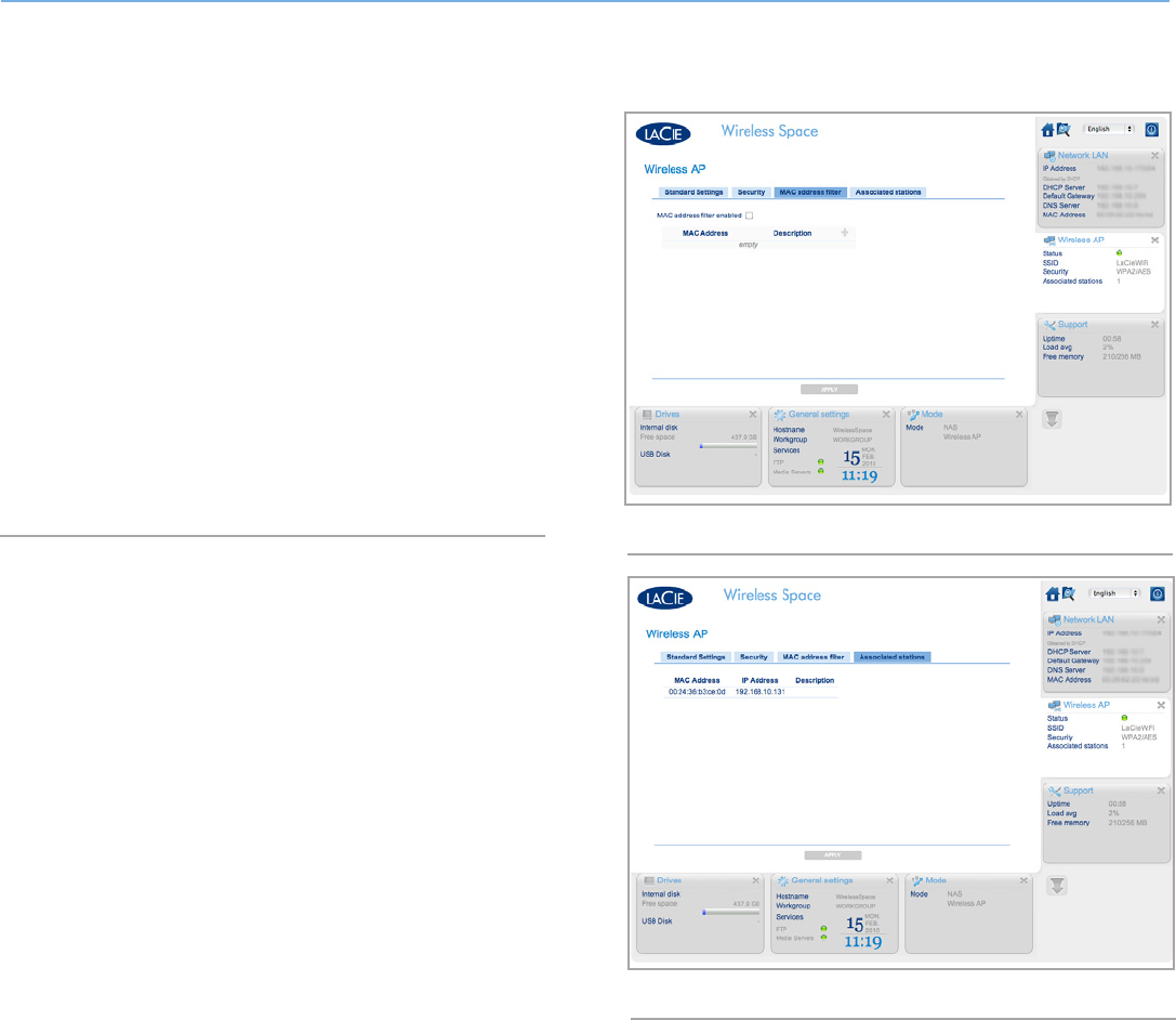
4.5.1.3. Wireless AP - MAC address filter
Add further security to the Wireless Space Wi-Fi by limiting who may
join the network by MAC address. Check the box for MAC address
filter enabled (Fig. 139) to activate a green addition symbol. Click
on the green plus sign to add each new MAC address that will have
access to the Wireless Space Wi-Fi.
The default for MAC address filtering is off. If it is enabled, only
those systems who have their MAC addresses registered in this tab
will have the right to use the Wireless Space Wi-Fi.
4.5.1.4. Wireless AP - Associated stations
This tab provides a list of devices that are using the Wireless Space
Wi-Fi (Fig. 140).
Fig. 140
Fig. 139
LaCie Wireless Space • DESIGN BY NEIL POULTON Administering the LaCie Wireless Space: Beyond Basic
User Manual page 85
4.5.2. Dashboard: Router Pages
A router configuration signifies the creation of a new network, or
sub-network. The Wireless Space will assign IP addresses to all con-
nected devices, wired and/or wireless. Router configurations have
three important Dashboard pages: Network WAN, Network LAN,
and Firewall.
Network LAN is included in the Basic administration section but the
page has a different meaning for router configurations. As a router,
the Wireless Space becomes the LAN interface for the network. As
a switch, the Network LAN page points to the router, server, or In-
ternet provider that manages IP addresses. See 3.6.6. Dashboard:
Network LAN for more information on the Network LAN page in a
switch configuration.
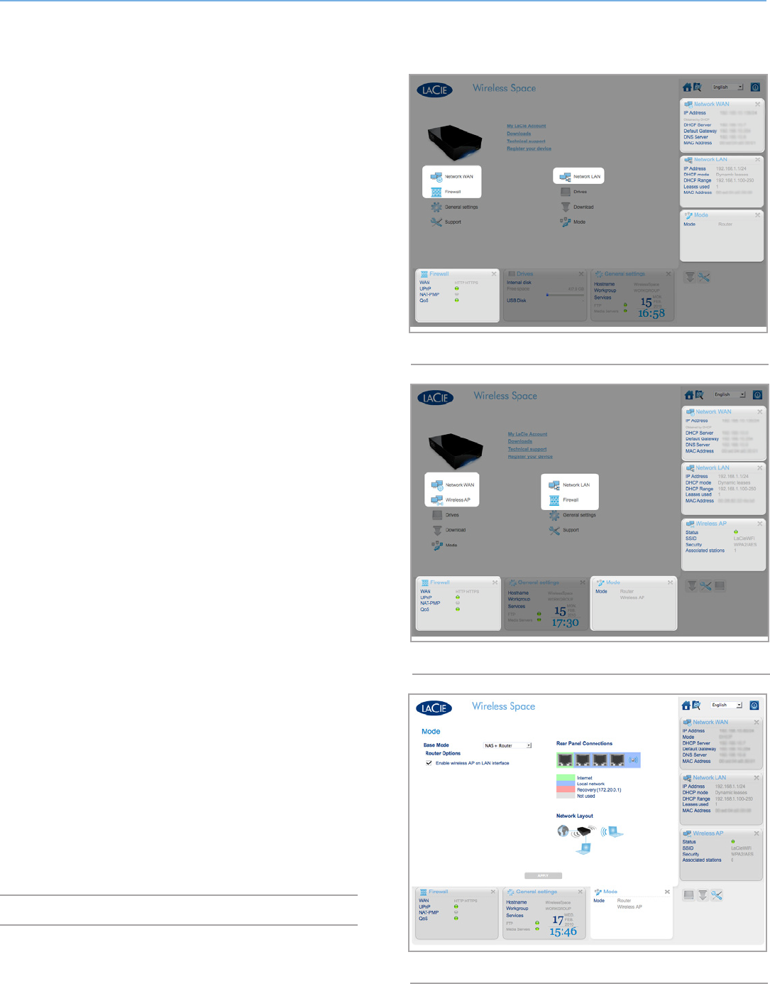
4.5.2.1. Dashboard Pages: Router - Wired Only
The welcome page for a NAS Router - Wired Only configuration is
pictured in Fig. 141 Router - Wired Only. The additional widgets
are highlighted.
For details on each page:
4.5.3. Dashboard: Network WAN
4.5.4. Dashboard: Network LAN
4.5.5. Dashboard: Firewall
4.5.2.2. Dashboard Pages: Router - Wireless Access
Point
Fig. 142 Router - Wireless Access Point shows the welcome page for
a NAS Router - Wireless Access Point.
Please note that this mode includes the widgets for a router and a
wireless access point. To enable the Wi-Fi access point on a Router -
Wired Only configuration, go to the Mode page. Once there, check
the box next to Enable wireless AP on LAN interface and click APPLY
(Fig. 143). The Router - Wireless Access Point pages include:
4.5.1. Dashboard: Wireless AP
4.5.3. Dashboard: Network WAN
4.5.4. Dashboard: Network LAN
4.5.5. Dashboard: Firewall
j
Fig. 141 Router - Wired Only
Fig. 142 Router - Wireless Access Point
Fig. 143
LaCie Wireless Space • DESIGN BY NEIL POULTON Administering the LaCie Wireless Space: Beyond Basic
User Manual page 86
4.5.3. Dashboard: Network WAN
Network WAN lists how the Wireless Space reaches the wide area
network (WAN) or Internet. The information is similar to the Network
LAN page in the Basic administration section (3.6.6. Dashboard:
Network LAN) with some additional options. The importance of this
page cannot be overstated since the proper settings prevent IP ad-
dressing conflicts with the router, server or Internet provider.
In a router configuration, the Ethernet cable is attached to the IN-
TERNET port (see 4.6. INTERNET Port: NAS+Router) on the back of
the Wireless Space. This is the connection from the Wireless Space
to the WAN or Internet, which makes it a client device to the rout-
er, server, or Internet provider. As a part of the WAN, the Wireless
Space must have its own IP address, assigned or static.
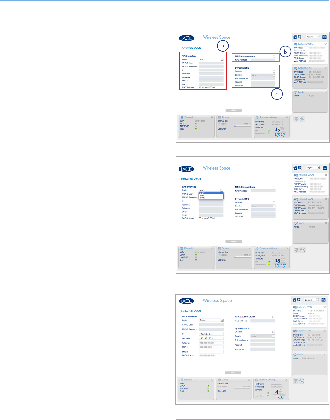
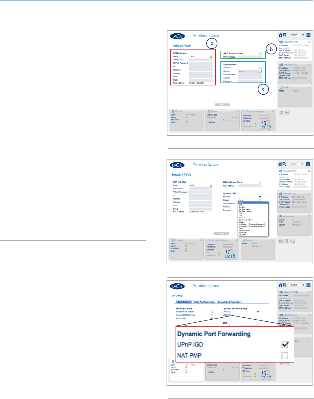
Network WAN
The default client IP mode for the Wireless Space is DHCP (Fig.
144). However, you may change the settings (Fig. 144, a and Fig.
145) to Static or PPPoE (point-to-point protocol over Ethernet) if your
network supports either setting. It is very important to complete all
the required fields for your network. Please refer to your network
router, server, or Internet provider for precision on the PPPoE User
(PPPoE only), PPPoE Password (PPPoE only), IP, Netmask, Gateway,
and DNS (if applicable). Fig. 146 shows an example of a static ad-
dress.
MAC Address Clone
If your router, server, or Internet provider limits devices connected to
its network by MAC address, you can set up a MAC Address Clone
(Fig. 144, b). As a default, this setting is turned off but clicking the
box will open the field to enter a MAC address. After you click APPLY
to confirm the setting adjustment, the WAN router, server, or Internet
provider will only list that MAC address among all the devices con-
nected to the Wireless Space network.
continued on the next page>>
Fig. 144
Fig. 145
Fig. 146
LaCie Wireless Space • DESIGN BY NEIL POULTON Administering the LaCie Wireless Space: Beyond Basic
User Manual page 87
Dynamic DNS
You can manage your Wireless Space while away from the network
by enabling Dynamic DNS (Fig. 147, c). Please note that you must
also create a Dynamic DNS account with a third-party provider on
its web site. There are many companies that offer free remote access
service using Dynamic DNS (see the pulldown menu after enabling
the feature, Fig. 148).
Once you have selected a company and created an account on its
web site, enter the pertinent information in the fields:
✦Full Hostname , Account, and Password
When all the fields are completed, click APPLY.
There are two additional settings that may also be required for Dy-
namic DNS to work: UPnP IGD and NAT-PMP. Both settings are
available on the Firewall page (4.5.5. Dashboard: Firewall). By de-
fault, UPnP IGD is enabled (Fig. 149). The demand for both settings
is wholly dependent upon the program being used for remote access
as well as many other factors.
Once Dynamic DNS is established, you can access the Dashboard
on computers that are outside of the Wireless Space network. Please
note that Internet service is required. Also, the web address used to
remotely view the Dashboard is the full hostname determined by the
service that has been chosen.
For more information, watch LaCie’s screencast tutorial on setting
up Dynamic DNS at: http://www.lacie.com/us/support/faq/faq.
htm?faqid=10706
Fig. 147
Fig. 148
Fig. 149
LaCie Wireless Space • DESIGN BY NEIL POULTON Administering the LaCie Wireless Space: Beyond Basic
User Manual page 88
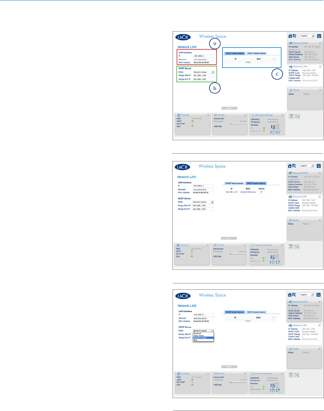
4.5.4. Dashboard: Network LAN
Use this page to manage the Wireless Space network.
LAN Interface
The default router address for the Wireless Space is 192.168.1.1
(Fig. 150, a and 1.9. Default Settings). Many routers and Internet
providers share the same default router IP address. Please check
the user manual for your WAN or Internet device to determine its
IP addressing information. If the addresses are the same, you must
change one of them before the Wireless Space is connected to the
WAN. It is important to check the Netmask address as well in order
to avoid further IP addressing conflicts. See 4.5.4.1. Avoiding Router
IP Address Conflicts: Example
DHCP Server
This small section shows the how the Wireless Space will assign IP
addresses to devices connected to its network and the range of IP
addresses that may be used. The Mode pulldown menu shows how
the DHCP server assigns IP address:
✦Disabled - DHCP assigning turned off
✦Static Leases - Each device is assigned an IP address that
never changes.
✦Dynamic Leases - The IP addresses assigned to devices may
change. This is the default setting.
✦Both - The Wireless Space uses Static and Dynamic leases.
Devices attached to the LAN ports on the Wireless Space will have
IP addresses (assigned by DHCP or static) that are within the range
of addresses from Range Start IP and Range End IP. Note that the
Range Start IP default is 192.168.1.100. The Range End IP default
is 192.168.1.250. The first three fields, 192.168.1, match the rout-
er IP address. This is critical for communication between the devices
connected to the Wireless Space network as well as communica-
tion with the Wireless Space itself. Just as important is the last field,
which must conform to the numbers in the start and end ranges. In
this case, any number between 100 and 250. Therefore, devices
can have IP addresses such as 192.168.1.100, 192.168.1.151,
192.168.1.207, etc.
The tabs in Fig. 150, c show devices on the Wireless Space network
by DHCP static leases or DHCP leases status.
continued on the next page>>
Fig. 150
Fig. 151
Fig. 152
LaCie Wireless Space • DESIGN BY NEIL POULTON Administering the LaCie Wireless Space: Beyond Basic
User Manual page 89
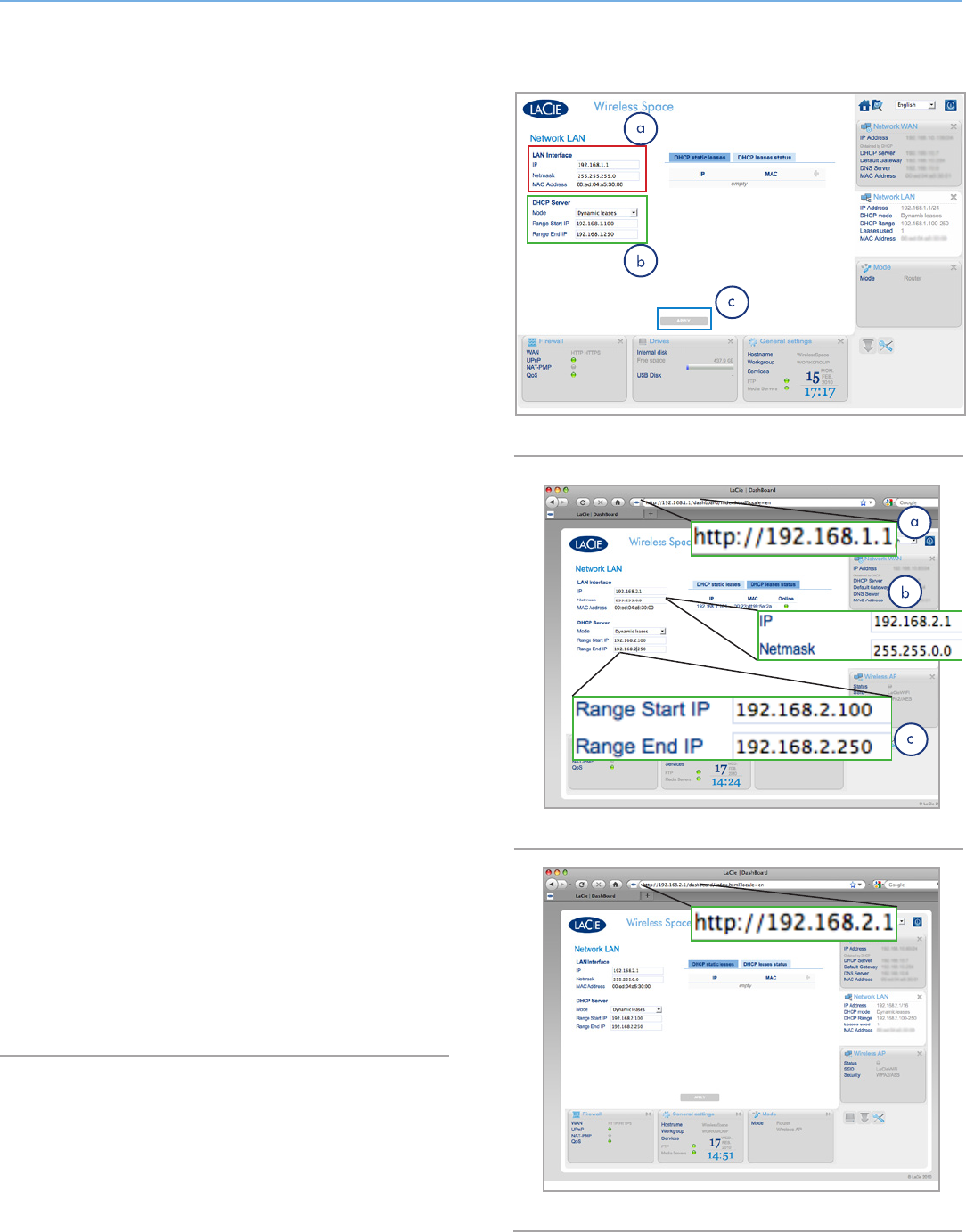
4.5.4.1. Avoiding Router IP Address Conflicts: Example
My Internet provider has a router IP address of 192.168.1.1 and a
Netmask of 255.255.255.0.
Since the Wireless Space defaults are the same, I must change the
router IP settings on one device. I decide to make changes on the
Wireless Space before attaching the Ethernet cable to the Internet
provider via the INTERNET port (1.4.2. Rear View).
To begin, I make certain that my computer’s network address set-
tings are DHCP and attach the Ethernet cable to one of the LAN
ports on the back of the Wireless Space (1.4.2. Rear View). To begin
making changes in the Wireless Space settings, I type the router IP
address in the URL window of my web browser for access to the
Dashboard (Fig. 154, a).
On the Network LAN page, I change the LAN Interface IP from the
default (Fig. 153, a) to 192.168.2.1 (Fig. 154, b). For the Netmask,
I select 255.255.0.0 (Fig. 154, b). I have now started to adjust the
settings that will prevent addressing conflicts on the network.
However, I still need to make a change in the range of IP addresses
(Fig. 153, b) so that devices on the Wireless Space network can
communicate with the Wireless Space and each other. The range
must match the router IP address to communicate with the Wireless
Space. I change the Range Start IP from the default (Fig. 153, b)
to 192.168.2.100 and the Range End IP to 192.168.2.250 (Fig.
154, c).
Once all the important fields have been completed, I click APPLY
(Fig. 153, c). The Dashboard will lose connection while the Wireless
Space executes the changes.
After a few moments, I type the new router IP address in the URL win-
dow of my web browser to launch the Dashboard (Fig. 155). After
confirming that all the settings have been changed, I know that the
Wireless Space will no longer have router addressing conflicts with
the router, server, or Internet provider.
Please note that there are many addressing possibilities to use for
the fields on the Network LAN page. LaCie cautions users to pay
close attention to addressing conflicts, both on the WAN and the
Wireless Space network.
Fig. 153
Fig. 154
Fig. 155
LaCie Wireless Space • DESIGN BY NEIL POULTON Administering the LaCie Wireless Space: Beyond Basic
User Manual page 90
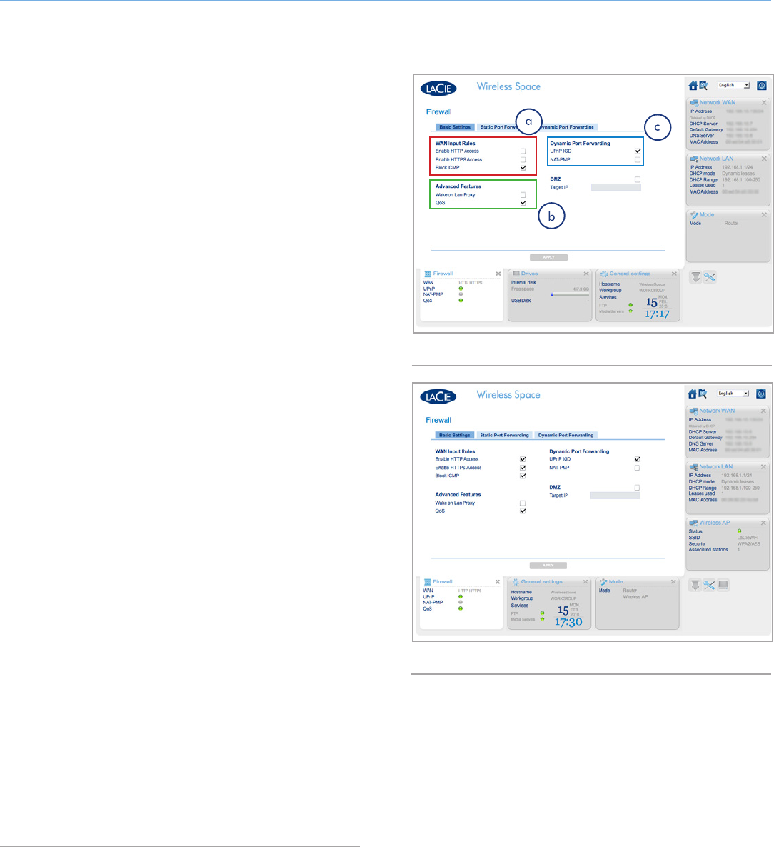
4.5.5. Dashboard: Firewall
DMZ, port forwarding, and NAT-PMP are among the advanced fea-
tures offered by the Wireless Space on the Firewall page. We have
provided a lengthy glossary (5. Glossary) at the back of this User
Manual to learn more.
This page is divided into three tabs: Basic Settings, Static Port For-
warding, and Dynamic Port Forwarding. For those with a keen un-
derstanding of port forwarding, the interface on the Static Port For-
warding tab is standard and easy to use.
4.5.5.1. Firewall Basic Settings - Internet Access
WAN Input Rules
As seen in Fig. 156, a, Enable HTTP Access and Enable HTTPS Ac-
cess are not checked by default. HTTP and HTTPS are the principle
means to find a web page when typing an address in your browser’s
URL window. Computers and other devices that are part of the Wire-
less Space network may require access to web pages for work or
leisure. However, as a means of protection, access to the Internet is
closed when first using your Wireless Space.
To open the Internet to devices on the Wireless Space network,
check each of the boxes and click APPLY. See Fig. 157.
Advanced Features
Wake on LAN Proxy allows packets from outside the Wireless Space
network to reach member devices. For example, if a user wanted
access to one of the devices on the Wireless Space network from a
device on another network.
For the protection of the Wireless Space network and the member
devices, Wake on LAN Proxy is disabled by default (Fig. 156, b). To
enable remote access to computers or other devices on the Wireless
Space, check the box for Wake on LAN Proxy and click APPLY.
Dynamic Port Forwarding
The UPnP IGD feature is enabled by default. For those who want to
use UPnP/DLNA devices for playback of media stored on the Wire-
less Space, it is recommended to keep this feature on. Additionally,
UPnP IGD and NAT-PMP should be enabled to use Dynamic DNS
(see 4.5.3. Dashboard: Network WAN).
Fig. 156
Fig. 157