Generac Power Systems 6 8L Users Manual Cover010 Rev0 8 05
6.8L to the manual 3474b1f8-1f0f-4e68-9bdc-91902a3c3864
2015-02-09
: Generac-Power-Systems Generac-Power-Systems-6-8L-Users-Manual-559909 generac-power-systems-6-8l-users-manual-559909 generac-power-systems pdf
Open the PDF directly: View PDF ![]() .
.
Page Count: 80
STANDBY GENERATOR
OWNER'S MANUAL
This manual should remain with the unit.
A new standard of reliability
Serial Number QT
6.8L
100kW
Models
Cover010 Rev. 0 08/05 Part No. 0F3605

Standby Generator Sets
Table of Contents
SECTION PAGE
SAFETY RULES ................................................ 1-1
INTRODUCTION .....................................................1-3
Read this Manual Thoroughly ...................................1-3
Operation and Maintenance ......................................1-3
How to Obtain Service ..............................................1-3
IDENTIFICATION RECORD .....................................2-1
Data Label ................................................................2-1
EQUIPMENT DESCRIPTION ...................................3-1
Equipment Description ................................................3-1
Engine Oil Recommendations ......................................3-1
Coolant Recommendations...........................................3-1
ENGINE PROTECTIVE DEVICES ............................4-1
Coolant Temperature Sensing ...................................4-1
Low Coolant Level .....................................................4-1
Oil Pressure Sensing .................................................4-1
Overcrank Shutdown ................................................4-1
Overspeed Shutdown ................................................4-1
RPM Sensor Loss Shutdown .....................................4-1
DC Fuse ....................................................................4-1
FUEL SYSTEMS .....................................................5-1
Fuel Requirements ....................................................5-1
Natural Gas Fuel System ..........................................5-1
Propane Vapor Withdrawal Fuel System....................5-1
LP Fuel System .........................................................5-1
SPECIFICATIONS ...................................................6-1
Generator .................................................................6-1
Engine.......................................................................6-1
Cooling System .........................................................6-1
Fuel System ..............................................................6-1
Electrical System ......................................................6-1
Cold Weather Kit .......................................................6-2
5.4L & 6.8L Ignition Description .................................6-3
Ignition Power-up Input (“56 Line Input”) .................6-3
Ignition Enable (“14 Line Input”) ..............................6-3
Ignition Shutdown on Loss of Crank
or CAM Signals .........................................................6-3
Diagnostic Blink Patterns (Red LED Located
on the Ignition Control Board ...................................6-3
GENERAL INFORMATION .......................................7-1
Generator AC Lead Connections ..................................7-1
Four-lead, Single-phase Stator ..................................7-1
Alternator Power Winding Connections ........................7-1
3-phase Alternators ..................................................7-1
INSTALLATION .......................................................8-1
Installation ...................................................................8-1
Preparation Before Start-up .........................................8-1
Transfer Switch ........................................................8-1
Fuel System ..............................................................8-1
Generator Set Lubrication ........................................8-1
Prior to Initial Start-up .............................................8-1
Initial Inspection for QT Genset Start-up .....................8-2
Start-up Inspection ...................................................8-2
OPERATION ...........................................................9-1
Generator Control and Operation ................................9-1
Operating Unit with Automatic Transfer Switch ...........9-1
Operating Unit with Manual Transfer Switch ...............9-1
Engine Start-up and Transfer ...................................9-1
Retransfer and Shutdown .........................................9-1
MAINTENANCE .....................................................10-1
Maintenance Performed by Authorized
Service Facilities .....................................................10-1
Cooling System ..........................................................10-1
Checking Fluid Levels ................................................10-1
Check Engine Oil ....................................................10-1
Battery Fluid ...........................................................10-1
Engine Coolant .......................................................10-2
Maintenance Owner/Operator Can Perform ................10-2
Check Engine Oil Level ...........................................10-2
Check Battery .........................................................10-2
Exercise System ......................................................10-2
Inspect Cooling System ...........................................10-2
Check Engine Coolant Level....................................10-2
Perform Visual Inspection .......................................10-2
Inspect Exhaust System ..........................................10-2
Check Fan Belt ........................................................10-2
Inspect Engine Governor ........................................10-2
Changing Engine Oil ...............................................10-2
Changing the Engine Air Cleaner ............................10-3
Spark Plugs ............................................................10-3
Coolant Change .......................................................10-3
Miscellaneous Maintenance ........................................10-3
Cleaning the Generator ...........................................10-3
Battery ....................................................................10-4
Battery Maintenance ...............................................10-4
Battery Replacement ...............................................10-4
SERVICE SCHEDULE ...........................................11-1
30 kW - 150 kW Standby Gas Engine
Driven Generator Sets ............................................11-1
TROUBLESHOOTING ...........................................12-1
Troubleshooting Guide ...............................................12-1
NOTES
EXPLODED VIEWS & PARTS LISTS
WIRING DIAGRAMS & SCHEMATICS
WARRANTY
Content003 Rev. 0 08/05
Study these SAFETY RULES carefully before install-
ing, operating or servicing this equipment. Become
familiar with this Owner’s Manual and with the unit.
The generator can operate safely, efficiently and reli-
ably only if it is properly installed, operated and
maintained. Many accidents are caused by failing to
follow simple and fundamental rules or precautions.
The manufacturer cannot anticipate every possible
circumstance that might involve a hazard. The warn-
ings in this manual, and on tags and decals affixed
to the unit are, therefore, not all inclusive. If a pro-
cedure, work method or operating technique is used
that the manufacturer does not specifically recom-
mend, ensure that it is safe for others. Also make
sure the procedure, work method or operating tech-
nique utilized does not render the generator unsafe.
DANGER
Despite the safe design of this generator,
operating this equipment imprudently, neglect-
ing its maintenance or being careless can cause
possible injury or death. Permit only responsible
and capable persons to install, operate or main-
tain this equipment.
Potentially lethal voltages are generated by
these machines. Ensure all steps are taken to
render the machine safe before attempting to
work on the generator.
Parts of the generator are rotating and/or hot
during operation. Exercise care near running
generators.
GENERAL HAZARDS
• For safety reasons, the manufacturer recommends
that this equipment be installed, serviced and
repaired by an Authorized Service Dealer or other
competent, qualified electrician or installation tech-
nician who is familiar with applicable codes, stan-
dards and regulations. The operator also must
comply with all such codes, standards and regula-
tions.
• Installation, operation, servicing and repair of this
(and related) equipment must always comply with
applicable codes, standards, laws and regulations.
Adhere strictly to local, state and national electri-
cal and building codes. Comply with regulations
the Occupational Safety and Health Administration
(OSHA) has established. Also, ensure that the
generator is installed, operated and serviced in
accordance with the manufacturer’s instructions
and recommendations. Following installation, do
nothing that might render the unit unsafe or in
noncompliance with the aforementioned codes,
standards, laws and regulations.
• The engine exhaust fumes contain carbon monox-
ide gas, which can be DEADLY. This dangerous gas,
if breathed in sufficient concentrations, can cause
unconsciousness or even death. For that reason,
adequate ventilation must be provided. Exhaust
gases must be piped safely away from any building
or enclosure that houses the generator to an area
where people, animals, etc., will not be harmed.
This exhaust system must be installed properly, in
strict compliance with applicable codes and stan-
dards.
• Keep hands, feet, clothing, etc., away from drive
belts, fans, and other moving or hot parts. Never
remove any drive belt or fan guard while the unit
is operating.
• Adequate, unobstructed flow of cooling and venti-
lating air is critical in any room or building hous-
ing the generator to prevent buildup of explosive
gases and to ensure correct generator operation.
Do not alter the installation or permit even partial
blockage of ventilation provisions, as this can seri-
ously affect safe operation of the generator.
• Keep the area around the generator clean and
uncluttered. Remove any materials that could
become hazardous.
• When working on this equipment, remain alert
at all times. Never work on the equipment when
physically or mentally fatigued.
• Inspect the generator regularly, and promptly
repair or replace all worn, damaged or defective
parts using only factory-approved parts.
SAVE THESE INSTRUCTIONS – The manufacturer suggests that these rules for safe
operation be copied and posted in potential hazard areas. Safety should be stressed to all
operators, potential operators, and service and repair technicians for this equipment.
The engine exhaust from this product
contains chemicals known to the state
of California to cause cancer, birth
defects or other reproductive harm.
WARNING:
This product contains or emits chemicals
known to the state of California to cause
cancer, birth defects or other reproductive harm.
WARNING:
1-1
Standby Generator Sets
Important Safety Instructions
Safety 001 Rev. 0 08/05

• Before performing any maintenance on the gen-
erator, disconnect its battery cables to prevent
accidental start-up. Disconnect the cable from the
battery post indicated by a NEGATIVE, NEG or (–)
first. Reconnect that cable last.
• Never use the generator or any of its parts as a
step. Stepping on the unit can stress and break
parts, and may result in dangerous operating con-
ditions from leaking exhaust gases, fuel leakage,
oil leakage, etc.
ELECTRICAL HAZARDS
• All generators covered by this manual produce
dangerous electrical voltages and can cause fatal
electrical shock. Utility power delivers extremely
high and dangerous voltages to the transfer switch
as well as the standby generator. Avoid contact
with bare wires, terminals, connections, etc., on
the generator as well as the transfer switch, if
applicable. Ensure all appropriate covers, guards
and barriers are in place before operating the gen-
erator. If work must be done around an operating
unit, stand on an insulated, dry surface to reduce
shock hazard.
• Do not handle any kind of electrical device while
standing in water, while barefoot, or while hands or
feet are wet. DANGEROUS ELECTRICAL SHOCK
MAY RESULT.
• If personnel must stand on metal or concrete while
installing, operating, servicing, adjusting or repair-
ing this equipment, place insulative mats over a
dry wooden platform. Work on the equipment only
while standing on such insulative mats.
• The National Electrical Code (NEC) requires the
frame and external electrically conductive parts
of the generator to be connected to an approved
earth ground. This grounding will help prevent
dangerous electrical shock that might be caused
by a ground fault condition in the generator set or
by static electricity. Never disconnect the ground
wire.
• Wire gauge sizes of electrical wiring, cables and
cord sets must be adequate to handle the maxi-
mum electrical current (ampacity) to which they
will be subjected.
• Before installing or servicing this (and related)
equipment, make sure that all power voltage
supplies are positively turned off at their source.
Failure to do so will result in hazardous and pos-
sibly fatal electrical shock.
• Connecting this unit to an electrical system nor-
mally supplied by an electric utility shall be by
means of a transfer switch so as to isolate the
generator electric system from the electric utility
distribution system when the generator is operat-
ing. Failure to isolate the two electric system power
sources from each other by such means will result
in damage to the generator and may also result
in injury or death to utility power workers due to
backfeed of electrical energy.
• Generators installed with an automatic transfer
switch will crank and start automatically when
normal (utility) source voltage is removed or is
below an acceptable preset level. To prevent such
automatic start-up and possible injury to person-
nel, disable the generator’s automatic start circuit
(battery cables, etc.) before working on or around
the unit. Then, place a “Do Not Operate” tag on
the generator control panel and on the transfer
switch.
• In case of accident caused by electric shock, imme-
diately shut down the source of electrical power.
If this is not possible, attempt to free the victim
from the live conductor. AVOID DIRECT CONTACT
WITH THE VICTIM. Use a nonconducting imple-
ment, such as a dry rope or board, to free the vic-
tim from the live conductor. If the victim is uncon-
scious, apply first aid and get immediate medical
help.
• Never wear jewelry when working on this equip-
ment. Jewelry can conduct electricity resulting in
electric shock, or may get caught in moving com-
ponents causing injury.
FIRE HAZARDS
• Keep a fire extinguisher near the generator at all
times. Do NOT use any carbon tetra-chloride type
extinguisher. Its fumes are toxic, and the liquid
can deteriorate wiring insulation. Keep the extin-
guisher properly charged and be familiar with its
use. If there are any questions pertaining to fire
extinguishers, consult the local fire department.
EXPLOSION HAZARDS
• Properly ventilate any room or building housing
the generator to prevent build-up of explosive gas.
• Do not smoke around the generator. Wipe up any
fuel or oil spills immediately. Ensure that no com-
bustible materials are left in the generator com-
partment, or on or near the generator, as FIRE or
EXPLOSION may result. Keep the area surround-
ing the generator clean and free from debris.
• These generator sets may operate using one of
several types of fuels. All fuel types are potentially
FLAMMABLE and/or EXPLOSIVE and should be
handled with care. Comply with all laws regulat-
ing the storage and handling of fuels. Inspect the
unit’s fuel system frequently and correct any leaks
immediately. Fuel supply lines must be prop-
erly installed, purged and leak tested according to
applicable fuel-gas codes before placing this equip-
ment into service.
• Diesel fuels are highly FLAMMABLE. Gaseous
fluids such as natural gas and liquid propane
(LP) gas are extremely EXPLOSIVE. Natural gas
is lighter than air, and LP gas is heavier than air;
install leak detectors accordingly.
1-2
Standby Generator Sets
Important Safety Instructions
Safety 001 Rev. 0 08/05
1-3
INTRODUCTION
Thank you for purchasing this model of the standby
generator set product line.
Every effort was expended to make sure that the
information and instructions in this manual were
both accurate and current at the time the manual was
written. However, the manufacturer reserves the right
to change, alter or otherwise improve this product(s)
at any time without prior notice.
READ THIS MANUAL THOROUGHLY
If any portion of this manual is not understood, con-
tact the nearest Authorized Service Dealer for start-
ing, operating and servicing procedures.
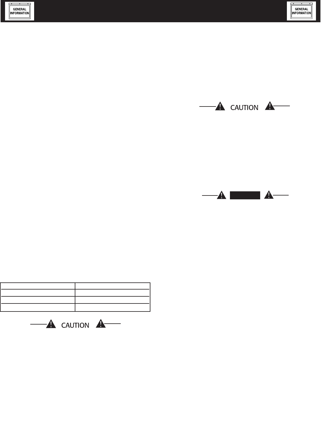
Throughout this publication, and on tags and
decals affixed to the generator, DANGER, WARNING,
CAUTION and NOTE blocks are used to alert person-
nel to special instructions about a particular service
or operation that may be hazardous if performed
incorrectly or carelessly. Observe them carefully.
Their definitions are as follows:
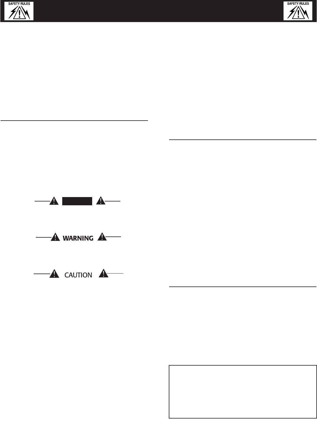
DANGER
After this heading, read instructions that, if not
strictly complied with, will result in personal injury
or property damage.
After this heading, read instructions that, if not
strictly complied with, may result in personal
injury or property damage.
After this heading, read instructions that, if not
strictly complied with, could result in damage to
equipment and/or property.
NOTE:
After this heading, read explanatory statements
that require special emphasis.
These safety warnings cannot eliminate the hazards
that they indicate. Common sense and strict compli-
ance with the special instructions while performing
the service are essential to preventing accidents.
Four commonly used safety symbols accompany the
DANGER, WARNING and CAUTION blocks. The type
of information each indicates is as follows:
This symbol points out important safety infor-
mation that, if not followed, could endanger
personal safety and/or property of others.
This symbol points out potential explosion
hazard.
This symbol points out potential fire hazard.
This symbol points out potential electrical shock
hazard.
The operator is responsible for proper and safe use
of the equipment. The manufacturer strongly recom-
mends that the operator read this Owner's Manual
and thoroughly understand all instructions before
using this equipment. The manufacturer also strong-
ly recommends instructing other users to properly
start and operate the unit. This prepares them if they
need to operate the equipment in an emergency.
OPERATION AND MAINTENANCE
It is the operator's responsibility to perform all safety
checks, to make sure that all maintenance for safe
operation is performed promptly, and to have the
equipment checked periodically by an Authorized
Service Dealer. Normal maintenance service and
replacement of parts are the responsibility of the
owner/operator and, as such, are not considered
defects in materials or workmanship within the terms
of the warranty. Individual operating habits and usage
contribute to the need for maintenance service.
Proper maintenance and care of the generator ensure
a minimum number of problems and keep operating
expenses at a minimum. See an Authorized Service
Dealer for service aids and accessories.
Operating instructions presented in this manual
assume that the standby electric system has been
installed by an Authorized Service Dealer or other
competent, qualified contractor. Installation of this
equipment is not a “do-it-yourself” project.
HOW TO OBTAIN SERVICE
When the generator requires servicing or repairs,
simply contact an Authorized Service Dealer for
assistance. Service technicians are factory-trained
and are capable of handling all service needs.
When contacting an Authorized Service Dealer or the
factory about parts and service, always supply the
complete model number of the unit as given on the
front cover of this manual or on the DATA LABEL
affixed to the unit.
AUTHORIZED SERVICE DEALER LOCATION
To locate the nearest AUTHORIZED
SERVICE DEALER, please call this number:
1-800-333-1322
or locate us on the web at:
www.generac.com
Standby Generator Sets
Important Safety Instructions
Safety 001 Rev. 0 08/05
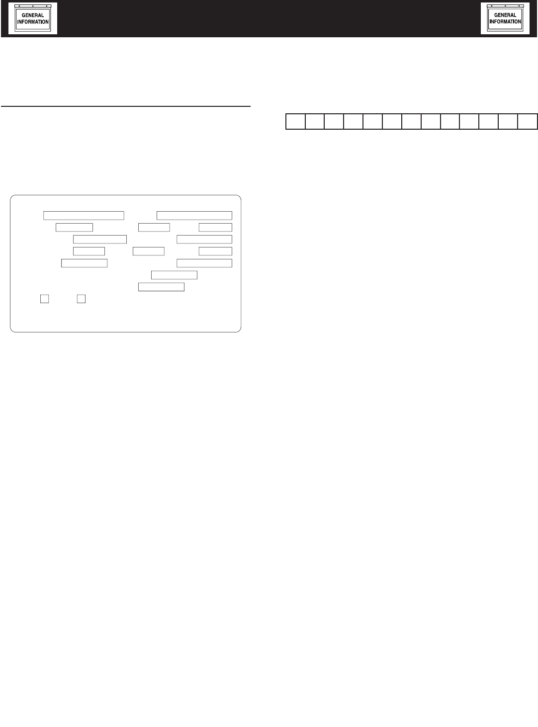
IDENTIFICATION RECORD
DATA LABEL
Every generator set has a DATA LABEL that contains
important information pertinent to the generator. The
data label, which can be found attached to the gen-
erator’s lower connection box, lists the unit’s serial
number and its rated voltage, amps, wattage capacity,
phase, frequency, rpm, power factor, etc.
WAUKESHA, WI
RATED KW
RATED VOLTAGE
POWER FACTOR
ENGINE RPM
ALTERNATOR SUBTRANSIENT REACTANCE
ALTERNATOR TRANSIENT REACTANCE
CLASS
MODEL
MADE IN USA
PRODUCTION DATE
GENERAC POWER SYSTEMS, INC.
HERTZ
RATED KVA
GENERATOR SET DATA
RATED AMPS
ALT RPM
PHASE
SERIAL
ROTOR STATOR WINDING INSULATION AT 25°C AMBIENT
NOTE:
For actual information related to this particular
model, please refer to the Manual Drawing Listing
located at the end of this manual, or to the data
label affixed to the unit.
Generator Model and Serial Number
This number is the key to numerous engineering and
manufacturing details pertaining to your unit. Always
supply this number when requesting service, order-
ing parts or seeking information.
Identification Code
Use this code to obtain important information about
the generator. For example, if the code is:
M — Designates generators capable of paralleling.
NOTE: Only 100kW and 150kW, 6.8L units
are currently available for this configura-
tion.
QT — Quiet Test Generator Series
100 — kw Rating
5.4 — Engine Size in Liters
A — Voltage Code: A = 120/240, Single-phase;
G = 120/208, Three-phase; K = 277/480,
Three-phase; J = 120/240, Three-phase;
L = 346/600, Three-phase
N — Fuel: N = Natural Gas; V = Vapor Propane
S — Enclosure Material: A = Aluminum; S
= Steel (Corrosion Resistant Aluminum
Enclosure Material, Steel is Standard)
N — Emission Equipment: N = No Equipment;
Y = Catalytic Converter and Air/Fuel Ratio
Controller
A — Industrial Dealer Product
Voltage Codes
The identification code letter following the unit’s
engine size is the generator’s “voltage code.”
Groups and Assembly Numbers
The manual drawing listing lists the groups and cor-
responding assembly numbers for each unit. The
assembly numbers refer to exploded view drawing
numbers that are applicable to the specific generator
model. These drawings are located in the back half
of this manual.
2-1
Standby Generator Sets
General Information
Identy001 Rev. C 04/06
M Q T 1 0 0 5 4 A N S N A
EQUIPMENT DESCRIPTION
This equipment is a revolving field, alternating cur-
rent generator set. It is powered by a gaseous fueled
engine operating at 1800 rpm for 4-pole direct drive
units, 3600 rpm for 2-pole direct drive units and
2300 - 3000 rpm for quiet drive gear units. See the
Specifications section for exact numbers. The unit
comes complete with a sound attenuated enclosure,
internally mounted muffler, control console, main-
line circuit breaker, battery charger, and protective
alarms as explained in the following paragraph.
All AC connections, including the power leads from
the alternator, 120 volt battery charger input and
control connections to the transfer switch are avail-
able in the main connection box.
The generator incorporates the following generator
features:
• Rotor and Stator insulation is Class H rated as
defined by NEMA MG1-32.6, NEMA MG1-1.66.
The generator is self ventilated and drip-proof con-
structed.
• The voltage waveform deviation, total harmonic
content of the AC waveform and telephone influ-
ence factor have been evaluated and are acceptable
according to NEMA MG1-32.
ENGINE OIL RECOMMENDATIONS
The unit has been filled with 15W-40 engine oil at
the factory. Use a high-quality detergent oil classified
“For Service CC, SD, SE, SF.” Detergent oils keep the
engine cleaner and reduce carbon deposits. Use oil
having the following SAE viscosity rating, based on
the ambient temperature range anticipated before the
next oil change:
Any attempt to crank or start the engine before
it has been properly serviced with the recom-
mended oil may result in an engine failure.
NOTE:
For temperatures below 32° F, it is strongly recom-
mended to use the optional Cold Weather Start Kit
(part number listed in the Specification Section).
The oil grade for temperatures below 32° F is 5W-
30 synthetic oil.
COOLANT RECOMMENDATIONS
Use a mixture of half low silicate ethylene glycol
base anti-freeze and deionized water. Cooling system
capacity is listed in the specifications. Use only deion-
ized water and only low silicate anti-freeze. If desired,
add a high quality rust inhibitor to the recommended
coolant mixture. When adding coolant, always add
the recommended 50-50 mixture.
Do not use any chromate base rust inhibitor
with ethylene glycol base anti-freeze or chro-
mium hydroxide (“green slime”) forms and will
cause overheating. Engines that have been oper-
ated with a chromate base rust inhibitor must
be chemically cleaned before adding ethylene
glycol base anti-freeze. Using any high silicate
anti-freeze boosters or additives will also cause
overheating. The manufacturer also recommends
that any soluble oil inhibitor is NOT used for this
equipment.
DANGER
Do not remove the radiator pressure cap while
the engine is hot or serious burns from boiling
liquid or steam could result.
Ethylene glycol base antifreeze is poisonous.
Do not use mouth to siphon coolant from the
radiator, recovery bottle or any container. Wash
hands thoroughly after handling. Never store
used antifreeze in an open container because
animals are attracted to the smell and taste of
antifreeze even though it is poisonous to them.
Temperature Oil Grade (Recommended)
Above 80° F (27° C) SAE 30W or 15W-40
32° to 80° F (0° to 27° C) SAE 20W-20 or 15W-40
Below 32° F (0° C) See Note
3-1
Standby Generator Sets
Equipment Description
Equip001 Rev. 0 08/05

ENGINE PROTECTIVE DEVICES
The standby generator may be required to operate for
long periods of time without an operator on hand to
monitor such engine conditions as coolant tempera-
ture, oil pressure or rpm. For that reason, the engine
has several devices designed to protect it against
potentially damaging conditions by automatically
shutting down the unit when the oil pressure is too
low, the coolant temperature is too high, the coolant
level is too low, or the engine is running too fast.
NOTE:
Engine protective switches and sensors are men-
tioned here for the reader's convenience. Also refer
to the applicable control panel manual for addi-
tional automatic engine shutdown information.
COOLANT TEMPERATURE SENSING
An analog Water Temperature Sender (WTS) is locat-
ed in the engine's cooling system. This sender is con-
nected to the panel and allows the panel to monitor
and display the temperature of the coolant system.
The WTS is a resistive device whose resistance chang-
es based on coolant temperature. The resistance of
the sender results in a voltage being developed across
the sender. As the Coolant temperature increases,
the resistance will decrease, causing the voltage to
decrease. This changing voltage is converted to 4-
20mA signal by a signal conditioner module. The
corresponding 4-20mA signal is read by the control
panel and displayed as the coolant temperature.
The control panel will monitor and display the cool-
ant temperature anytime the DC input to the control
panel is present.
If the temperature exceeds approximately 140° C
(284° F), the engine shutdown will be initiated. The
generator will automatically restart and the display
will reset once the temperature has returned to an
operating level.
LOW COOLANT LEVEL
A Low Coolant Level (LCL) sensor is placed in the
generators coolant system. This sensor allows the
panel to detect a Low Coolant Level condition.
The LCL is a resistive device whose resistance changes
rapidly based on the presence or absence of coolant.
The resistance of the LCL results in a voltage being
developed across the LCL. This voltage changes as
the resistance changes. This changing voltage is con-
verted to 4-20mA signal by a signal conditioner mod-
ule. The corresponding 4-20mA signal is read by the
control panel and displayed as the low coolant level.
If the level of the engine coolant drops below the level
of the low coolant level sensor, the engine shutdown
will be initiated.
OIL PRESSURE SENSING
An analog Oil Pressure Sender (OPS) is used for
monitoring the engine oil pressure. This sender
allows the control panel to measure and display the
Engine oil pressure.
The OPS is a resistive device, whose resistance
changes based on engine oil pressure. The resistance
of the sender results in a voltage being developed
across the sender. As the oil pressure increases,
the resistance will decrease, causing the voltage to
decrease. This changing voltage is converted to 4-
20mA signal by a signal conditioner module. The
corresponding 4-20mA signal is read by the control
panel and displayed as the oil pressure.
The control panel will monitor and display oil pres-
sure anytime the DC input to the control panel is
present.
Should the oil pressure drop below the 8 psi range,
the engine shutdown is initiated. The unit should not
be restarted until oil is added. Turn the AUTO/OFF/
MANUAL switch to the OFF position, then back to
AUTO to restart.
OVERCRANK SHUTDOWN
When the control panel receives a start signal, it ini-
tiates the programmed starting sequence. The start
sequence consists of the number of crank attempts,
the length of each crank attempt, and the rest time
between each crank attempt. If the engine has not
started by the end of the final crank attempt, an
Overcrank alarm is generated, the control panel will
sound the alarm and display the message "Failed to
start".
OVERSPEED SHUTDOWN
A speed circuit controls engine cranking, start-up,
operation and shutdown. Engine speed signals are
delivered to the circuit board whenever the unit is
running. Should the engine over speed above a safe,
preset value, the circuit board initiates an automatic
engine shutdown. Contact the nearest Authorized
Dealer if this failure occurs.
RPM SENSOR LOSS SHUTDOWN
If the speed signal to the control panel is lost, engine
shutdown will occur.
DC FUSE
This fuse is located inside of the control panel. It
protects the panel wiring and components from
damaging overload. Always remove this fuse before
commencing work on the generator. The unit will
not start or crank if the fuse is blown. Replace the
fuse with one of the same size, type, and rating. (See
the exploded views and parts lists at the end of this
manual for replacement part number.)
4-1
Standby Generator Sets
Engine Protective Devices
EngProt002 Rev. B 10/05

FUEL SYSTEM
FUEL REQUIREMENTS
The standby generator may be equipped with one of
the following fuel systems:
• Natural gas fuel system
• Propane vapor (PV) fuel system
• Liquid propane (LP) fuel system
The Manual Drawing Listing that is affixed to the
unit includes the “Identification Code,” which may be
used to identify the type of fuel system installed on
the unit.
Recommended fuels should have a Btu content of at
least 1,000 Btu's per cubic foot for natural gas; or at
least 2,520 Btu's per cubic foot for LP gas. Ask the
fuel supplier for the Btu content of the fuel.
Required fuel pressure for natural gas is 11 inches
to 14 inches water column (0.4 to 0.5 psi); and for
liquid propane, 11 inches to 14 inches of water
column (0.4 to 0.5 psi).
NOTE:
Any piping used to connect the generator to the
fuel supply should be of adequate size to ensure
the fuel pressure NEVER drops below 11 inches
water column for natural gas or 11 inches water
column for liquid propane for all load ranges.
NOTE:
It is the responsibility of the installer to make sure
that only the correct recommended fuel is sup-
plied to the generator fuel system. Thereafter, the
owner/operator must make certain that only the
proper fuel is supplied.
NATURAL GAS FUEL SYSTEM
Natural gas is supplied in its vapor state. In most
cases, the gas distribution company provides piping
from the main gas distribution line to the standby
generator site. The following information applies to
natural gas fuel systems.
• Gas pressure in a building is usually regulated by
national, state and local codes.
• To reduce gas pressure to a safe level before
the gas enters a building, a primary regulator is
needed. The natural gas supplier may or may not
supply such a regulator.
• It is the responsibility of the gas supplier to make
sure sufficient gas pressure is available to operate
the primary regulator.
• Gas pressure at the inlet to the fuel shutoff sole-
noid should not exceed approximately 14 inches
water column (0.5 psi). Optimum pressure at the
fuel shutoff solenoid is 11 inches water column
(0.4 psi).
PROPANE VAPOR WITHDRAWAL FUEL SYSTEM
This type of system utilizes the vapors formed above
the liquid fuel in the supply tank. Approximately 10
to 20 percent of the tank capacity is needed for fuel
expansion from the liquid to the vapor state. The
vapor withdrawal system is generally best suited for
smaller engines that require less fuel. The installer
should be aware of the following:
• The natural gas and LP gas systems are similar.
However, the natural gas system delivers gas at a
pressure of approximately five inches water col-
umn to the carburetor.
• When ambient temperatures are low and engine
fuel consumption is high, the vapor withdrawal
system may not function efficiently.
• Ambient temperatures around the supply tank
must be high enough to sustain adequate vaporiza-
tion, or the system will not deliver the needed fuel
volume.
• In addition to the cooling effects of ambient air, the
vaporization process itself provides an additional
cooling effect.
LP FUEL SYSTEM
LP is supplied as a liquid in pressure tanks. It is
usually made up of propane, butane, or a mixture of
the two gases. Propane tends to vaporize readily even
at temperatures as low as -20° F (-29° C). However,
butane reverts to its liquid state when temperatures
drop below 32° F (0° C).
LP in a liquid withdrawal system must be converted
to its gaseous state before it is introduced into the
engine carburetor. A vaporizer-converter is generally
used to accomplish this. In such a converter, heated
engine coolant is ported through the converter to
provide the necessary heat for conversion of the fuel
from a liquid to a gaseous state.
5-1
Standby Generator Sets
Fuel Systems
FuelSys002 Rev. A 05/06

SPECIFICATIONS
GENERATOR
Type ............................................................................. Synchronous
Rotor Insulation ................................................................... Class H
Stator Insulation .................................................................. Class H
Total Harmonic Distortion ......................................................< 3.5%
Telephone Interference Factor (TIF) .......................................... < 50
Alternator Output Leads 3-phase ........................................... 6-wire
Bearings .........................................................................Sealed Ball
Coupling ..........................................................................Gear Drive
Load Capacity (Standby Rating) ..........................................100kW*
* NOTE: Generator rating and performance in accordance with ISO8528-5, BS5514, SAE J1349,
ISO3046 and DIN 6271 Standards. KW rating is based on LPG fuel and may derate with natural
gas.
Excitation System ............................................................. Brushless
Generator Output Voltage/kW - 60 Hz kW Amp CB Size
120/240V, 1-phase, 1.0 pf 100 417 450
120/208V, 3-phase, 0.8 pf 100 347 400
277/480V, 3-phase, 0.8 pf 100 150 175
Generator Locked Rotor KVA Available @ Voltage Dip of 35%
Single-phase or 208 3-phase ........................................... 200 KVA
480V, 3-phase .................................................................. 240 KVA
ENGINE
Make ................................................................................... Generac
Model ...................................................................................... V-type
Cylinders and Arrangement .......................................................... 10
Displacement ....................................................................... 6.8 Liter
Bore ...................................................................................... 3.55 in.
Stroke ................................................................................... 4.17 in.
Compression Ratio ..................................................................9-to-1
Air Intake System ...............................................Naturally Aspirated
Valve Seats ....................................................................... Hardened
Lifter Type .......................................................................... Hydraulic
Engine Parameters
Rated Synchronous RPM ..............................................60 Hz, 2300
HP at rated kW ................................................................60 Hz, 168
Exhaust System
Exhaust Flow at Rated Output 60 Hz .................................. 888 cfm
Exhaust Temperature at Rated Output .................................. 960° F
Combustion Air Requirements (Natural Gas)
Flow at rated power, 60 Hz ................................................. 262 cfm
Governor
Type .................................................................................. Electronic
Frequency Regulation ...................................................Isochronous
Steady State Regulation ......................................................± 0.25%
Adjustments:
Speed ............................................................................ Selectable
Engine Lubrication System
Type of Oil Pump ...................................................................... Gear
Oil Filter .............................................................Full Flow, Cartridge
Crankcase Oil Capacity ....................................................6 U.S. qts.
COOLING SYSTEM
Type ....................................................................................... Closed
Water Pump .................................................................... Belt Driven
Fan Speed ................................................................................ 1670
Fan Diameter .....................................................................26 inches
Fan Mode ................................................................................ Puller
Air Flow (inlet air including alternator and
combustion air) .......................................................... 5500 ft3/min.
Coolant Capacity ........................................................ (4.5 U.S. gal.)
Heat Rejection to Coolant ..........................................342,000 Btu/h
Maximum Operating Air Temp. on Radiator ..............60° C (150° F)
Maximum Ambient Temperature ................................50° C (140° F)
FUEL SYSTEM
Type of Fuel ..................................................LP Vapor/Natural Gas*
Carburetor ...................................................................... Down Draft
Secondary Fuel Regulator .................................................Standard
Fuel Shut-off Solenoid ........................................................Standard
Operating Fuel Pressure .................... 11 in. - 14 in. Water Column
Fuel Consumption - ft3/hr (Natural Gas/LPV)
Exercise 25% 50% 75% 100%
Cycle Load Load Load Load
130/52 371/149 713/287 991/400 1260/507
* Engine is not field convertible between natural gas and propane. Jet size and ignition timing are
factory set for the specific fuel.
ELECTRICAL SYSTEM
Battery Charge Alternator ............................................12V, 30 Amp
Static Battery Charger ....................................................12V, 2 Amp
Recommended Battery ................................................ 24F 525CCA
System Voltage .....................................................................12 Volts
Voltage Regulator
Type ................................................................................. Full Digital
Sensing ................................................................................ 3-phase
Regulation .............................................................................± 1/4%
Features ............................................ Built into H-100 Control Panel
V/F Adjustable, Adjustable
Voltage and Gain
Power Adjustment for Ambient Conditions
Temperature Deration
3% for every 10° C above °C ..................................................... 25
1.65% for every 10° above °F .................................................... 77
Altitude Deration
1% for every 100 m above m ................................................... 183
3% for every 1000 ft. above ft. ................................................. 600
Controller .............................................. H-panel
6-1
Standby Generator Sets
Specifications
GenSpec009 Rev. C 11/05
COLD WEATHER KIT
For cold climates, optional cold weather kit (part num-
ber 0F6148A) is recommended. The kit includes:
• Battery Warmer
• 4” Junction Box with hardware
• 700 Cold Cranking Amp Battery
• 6 qt. pack 5W-30 synthetic oil (engine)
• 1 qt. 75W90 synthetic gear oil (gear drive)
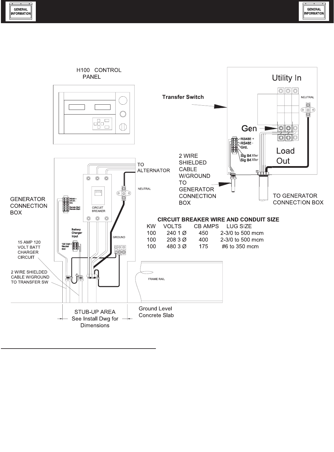
Figure 1 — Interconnections
6-2
Standby Generator Sets
Specifications
GenSpec009 Rev. C 11/05

5.4L & 6.8L IGNITION DESCRIPTION
This single-fire Ignition is intended to operate with
a 10-cylinder, 6.8L engine and an 8-cylinder, 5.4L
engine.
The 6.8L engine uses a 40-1 crank sensor, a mag-
pickup CAM sensor and individual coil-on-plug coils
for each spark-plug.
The 5.4L engine uses a 36-1 crank sensor, a mag-
pick-up CAM sensor and individual coil-on-plug coils
for each spark-plug.
With a single-fire ignition, each high-voltage coil out-
put is connected to one spark plug resulting in that
spark plug being fired only during the compression
cycle.
Engine Timing versus Engine Speed for the 6.8L
engine is:
RPM NG/LP Engine Timing (BTDC)
1800 rpm 22 degrees
3600 rpm 24 degrees
Engine Timing versus Engine Speed for the 5.4L
engine is:
RPM NG/LP Engine Timing (BTDC)
1800 rpm 26 degrees
3600 rpm 26 degrees
IGNITION POWER-UP INPUT ("56 LINE
INPUT")
When battery voltage is applied to this input the igni-
tion will power-up. For the ignition to power itself
down, battery voltage must be removed from this
input.
IGNITION ENABLE ("14 LINE INPUT")
This input must be connected to the +12V battery for
the ignition to turn-on the coils. If this input is con-
nected to battery ground the ignition will stop firing
the coils and will power down within approximately
2 seconds. In the event that an ignition fault has
occurred, however, the ignition will wait 60 seconds
before powering down. This allows time to view the
diagnostic LED located on the ignition board.
NOTE:
The ignition cover does not need to be removed to
see the LED.
IGNITION SHUTDOWN ON LOSS OF CRANK
OR CAM SIGNALS
The ignition will stop firing the coils immediately fol-
lowing the loss of the crank signal. The ignition will
stop firing the coils after approx. 3 seconds following
the loss of the cam signal.
DIAGNOSTIC BLINK PATTERNS (RED LED
LOCATED ON THE IGNITION CONTROL
BOARD)
During normal ignition operation the RED LED
flashes at a 0.5 sec ON and a 0.5 sec OFF rate. This
is considered one (1) blink.
LED Fault Code with Priority as shown:
1. No Crank Signal: LED blinks 2 times, is OFF for
3.0 seconds and then repeats
2. No CAM Signal: LED blinks 3 times, is OFF for
3.0 seconds and then repeats
Only one fault is displayed at a time. If multiple faults
exist then the highest priority fault must be resolved
prior to a lower priority fault being displayed. In the
event that an ignition fault has occurred the ignition
will wait 60 seconds before powering down.
NOTE:
The ignition cover does not need to be removed to
see the LED.
6-3
Standby Generator Sets
Specifications
GenSpec009 Rev. C 11/05
GENERATOR AC LEAD CONNECTIONS
See “Voltage Codes”. This generator may be rated
at any one of three voltages, either single-phase or
three-phase. The electrical wires in the unit’s AC con-
nection (lower) panel should be installed according to
the number of leads and the voltage/phase required
for the application. If there are any questions regard-
ing lead connection, refer to the wiring diagrams at
the back of this manual.
Voltage codes apply to the type of stator assembly
installed on a particular generator.
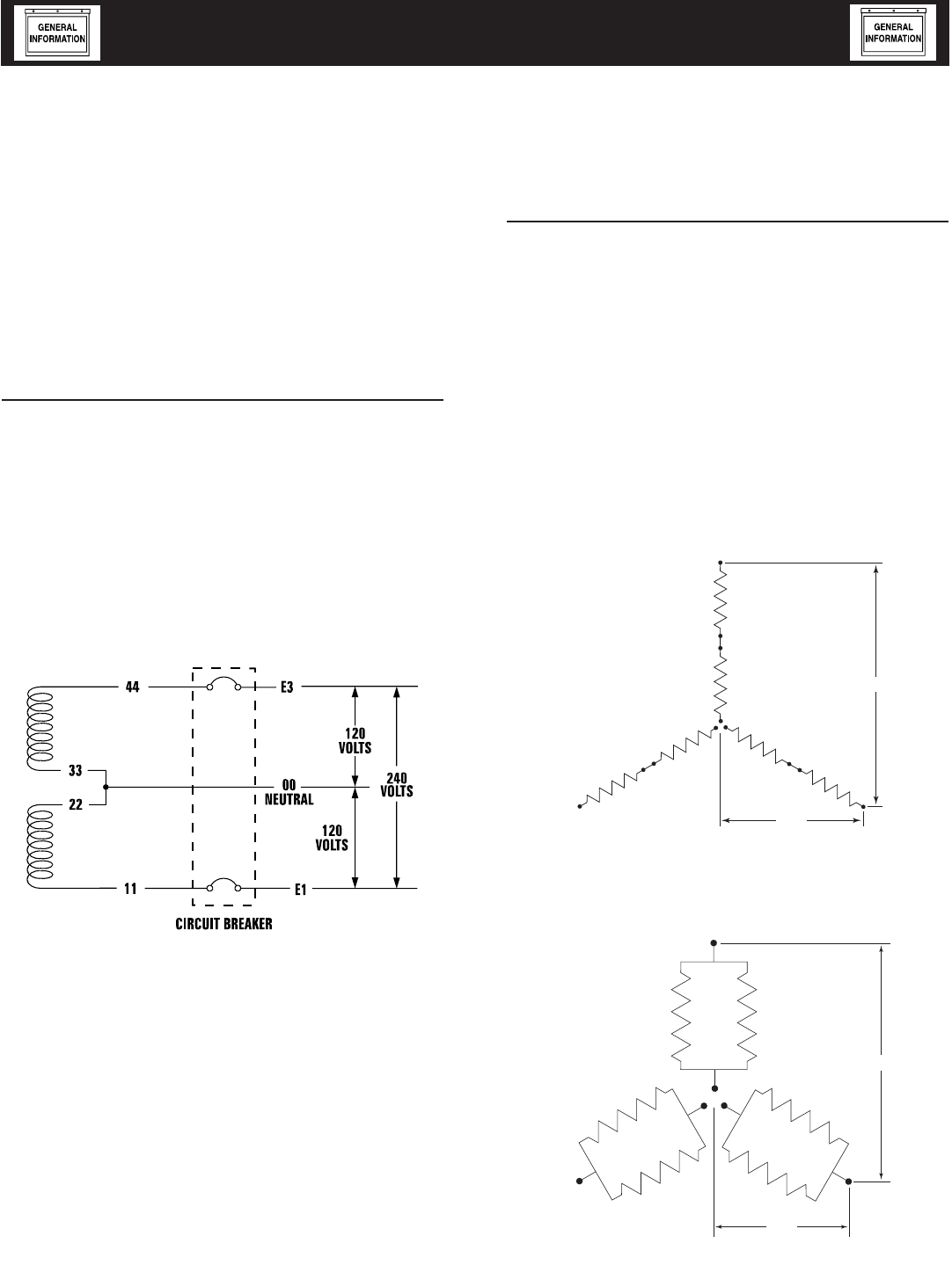
FOUR-LEAD, SINGLE-PHASE STATOR
Four-lead generators are built to supply electrical
loads with voltage code "A" (240V, 1-phase, 60Hz).
Electrical power is produced in the stator power
windings. These windings were connected at the fac-
tory to the main circuit breaker as shown in Figure
7.1.
The rated voltage between each circuit breaker ter-
minal is 240V. The rated voltage between each circuit
breaker terminal and the neutral point 00 is 120V.
Figure 7.1 — Four-lead, Single-phase Stator
ALTERNATOR POWER WINDING
CONNECTIONS
3-PHASE ALTERNATORS
The generator is designed to supply 3-phase electri-
cal loads. Electric power is produced in the alterna-
tor power windings. These windings were connected
at the factory to the main circuit breaker with a “Y”
configuration as shown in Figures 7.2 and 7.3.
The rated voltage between circuit breaker terminals
E1-E2, E1-E3 and E2-E3 is either 480V or 208V
depending on the model.
The rated voltage between each circuit breaker termi-
nal and the neutral point 00 is either 277V or 120V
depending on the model.
Figure 7.2 — Stator Power Winding
Connections - 3-phase, 277/480V (12 Lead)
E1
S1
S4
S7
S12 S11
S10
S8
S5
S2
E2
S9
S6
S3
E3 L - N
L - L
Figure 7.3 — Stator Power Winding
Connections - 3-phase, 120/208V (12 Lead)
E1
S10
S12
S4
S5
S2
S8
S11
S6
S3
S9
S7 S1
E2
E3
L - N
L - L
7-1
Standby Generator Sets
General Information
ACConn002 Rev. 0 08/05
INSTALLATION
Refer to the separate “Installation Guide QT Product
Line” supplied with the unit.
PREPARATION BEFORE START-UP
The instructions in this section assume that the
standby generator has been properly installed, ser-
viced, tested, adjusted and otherwise prepared for
use by a competent, qualified installation contractor.
Be sure to read the “Safety Rules”, as well as all other
safety information in this manual, before attempting
to operate this (and related) equipment.
Before starting the generator for the first time, the
installer must complete the following procedures. For
follow-up maintenance information and/or service
intervals, please refer to the “Maintenance” section
and the “Service Schedule”.
TRANSFER SWITCH
If this generator is used to supply power to any elec-
trical system normally powered by an electric utility,
the National Electrical Code requires that a transfer
switch be installed. The transfer switch prevents elec-
trical backfeed between two different electrical sys-
tems. (For additional information, see the applicable
transfer switch manual for this unit.) The transfer
switch, as well as the generator and other standby
components, must be properly located and mounted
in strict compliance with applicable codes, standards
and regulations.
FUEL SYSTEM
Make sure the fuel supply system to the genera-
tor (a) delivers the correct fuel at the correct pres-
sure and (b) is properly purged and leak tested
according to code. No fuel leakage is permitted. See
“Specifications” for more information.
GENERATOR SET LUBRICATION
Check the engine crankcase oil level before operating
and add oil to the proper level – the dipstick “FULL”
mark. Never operate the engine with the oil level
below the dipstick “ADD” mark. See “Specifications”
and “Engine Oil Recommendations”.
NOTE:
This engine is shipped from the manufacturer
with “break-in” oil. This oil should be changed
after 30 hours of operation.
Check the oil level in the generator gearbox (if so
equipped) prior to initial use and at the intervals
indicated by the “Service Schedule.” The recom-
mended oil is SAE 90 gear lubricant.
Also, if the engine is equipped with a mechanical gov-
ernor, make sure the governor is properly lubricated
with clean engine oil.
PRIOR TO INITIAL START-UP
Prior to initially starting the generator, it must
be properly prepared for use. Any attempt to
crank or start the engine before it has been
properly serviced with the recommended types
and quantities of engine fluids (oil, coolant, fuel,
etc.) may result in an engine failure.
ENGINE COOLANT
Have the engine cooling system properly filled with
the recommended coolant mixture. Check the system
for leaks and other problems. See “Specifications”
and “Coolant” sections.
BELT TENSION
Check-the engine-fan belt tension and condition prior
to placing the unit into service and at recommended
intervals. Belt tension is correct when a force of
approximately 22 pounds (10 kg), applied midway
between pulleys, deflects the belt about 3/8- to 5/8-
inch (10 to 16 mm).
ELECTRICAL SYSTEM
Make sure the generator is properly connected to an
approved earth ground.
Make sure the generator battery is fully charged,
properly installed and interconnected, and ready for
use.
Check to ensure that there are no loose electrical con-
nections. Restrain any loose wires to keep them clear
of any moving generator set components.
INITIAL INSPECTION FOR QT GENSET
STARTUP
Inspect for the following.
• Freight Damage.
• Manuals present.
• Fluid Levels (Oil, coolant, battery, Gear Drive).
• Correct fuel piping.
• Correct muffler installation for external applica-
tion.
• Adequate air flow, clearances and ventilation per
installation drawings and applicable codes.
• Correct AC and DC wire size, connections and
grounding. Control and communication wiring to/
from the transfer switch must be run in a separate
conduit from the AC power leads.
• Battery charger connection to 120 VAC.
• Communication wires connected between transfer
switch and generator (HTS only).
• Unit secured to pad.
8-1
Standby Generator Sets
Installation
Install001 Rev. C 05/06

START-UP CHECKLIST
Before working on the generator, ensure the fol-
lowing:
• The AUTO/OFF/MANUAL switch is in the OFF
position.
• The 120VAC supply to the battery charger is
switched OFF.
PREPARATION FOR START-UP
• Ensure that the 120VAC circuit breaker to the bat-
tery charger is open.
• Remove the fuse from the the control panel. For
the H-100 and R-series: Open the front door of the
control box and remove the 15 Amp ATO fuse in
the lower left-hand corner of the control box.
• Connect the battery cables to the battery. Attach
negative battery cable last.
• Close the 120VAC circuit breaker to the battery
charger.
• Measure the voltage at the battery before and after
the charger is turned on.
• Verify all AC electrical connections are tight at the
circuit breaker and transfer switch.
• Visually inspect entire area looking for loose paper,
plastic wrappings, leaves, etc.
• Check all hoses clamps fittings for leaks or dam-
age.
• Check all electrical plugs throughout the genera-
tor. Ensure each plug is seated correctly and fully
inserted into its receptacle.
• Verify the AUTO/OFF/MANUAL switch is in OFF
position.
• Open the valve to the engine fuel line.
• Bleed the fuel system of air. (necessary for long fuel
lines).
• Open the generator main line circuit breaker.
• Connect a manometer to the gas line and record
the static pressure. It must be as listed in the
Specifications.
• Insert the fuse into the control panel.
• Move the AUTO/OFF/MANUAL switch to the MAN-
UAL position. The engine should now crank and
start.
• Check voltage at the generator terminals.
• For 3-phase units, check phase rotation at the
transfer switch terminals. The generator phase
rotation must match the utility phase rotation.
• Check for coolant, fuel, oil, and exhaust leaks.
• Close the generators main line circuit breaker.
• Turn the generator set off.
• Connect the UTILITY supply to the transfer
switch.
• Set the AUTO/OFF/MANUAL switch to AUTO.
• Disconnect utility power before the transfer
switch.
Engine should start, transfer to load.
Run at least 15 minutes on generator power.
Make certain all 3-phase loads are functioning
correctly (correct phase rotation).
• Reconnect Utility power
Transfer switch will transfer back to Utility and
engine will shut down within the given time
parameters set up for the specific transfer switch
and controller.
• Install all covers, access plates and door panels.
• Put the Owners Manual in a safe and accessible
place.
• Make certain the AUTO/OFF/MANUAL switch is in
the AUTO position.
START-UP INSPECTION
When a start-up is performed by an Authorized
Service Dealer, a standard three-part form titled
“Start-up Inspection for Standby Power Systems”
(part no. 067377), should be completed by the instal-
lation technician or engineer. See page 1-3 for infor-
mation on locating the nearest Authorized Service
Dealer. The installer should complete the form and
disseminate copies as follows:
• White copy: Mail to Generac Warranty Department,
P.O. Box 340, 211 Murphy Dr., Eagle, WI 53119-
2062.
• Pink Copy: For service file of installing dealer.
• Yellow Copy: For the customer’s records.
8-2
Standby Generator Sets
Installation
Install001 Rev. C 05/06
GENERATOR CONTROL AND
OPERATION
Refer to the appropriate control panel operator’s
manual for this unit.
OPERATING UNIT WITH MANUAL
TRANSFER SWITCH
If the generator was installed in conjunction with a
transfer switch capable of manual operation only, the
following procedure applies. A manually operated
transfer switch is one that will not provide automatic
start-up and does not include an intelligence circuit.
ENGINE START-UP AND TRANSFER
For additional information, refer to the applicable
control panel manual for this unit, as well as any lit-
erature pertaining to the specific transfer switch.
DANGER
The Maintenance Disconnect Switch and the
AUTO/OFF/MANUAL switches (if so equipped)
must be set properly, or the generator will crank
and start as soon as the utility power to the
transfer switch is turned off. Refer to applicable
control panel and transfer switch manuals for
more information.
Do not proceed until certain that utility source
voltage is available to the transfer switch and
the transfer switch main contacts are set to
UTILITY.
Do not attempt manual operation until all power
supplies to the transfer switch have been posi-
tively turned off, or extremely dangerous - pos-
sibly lethal - electrical shock will result.
Transfer switch enclosure doors should be kept
closed and locked. Only authorized personnel
should be allowed access to the transfer switch
interior. Extremely high and dangerous voltages
are present in the transfer switch.
In order to transfer load from the utility source to the
generator, follow these directions:
• Turn OFF or disconnect the utility power circuit
to the transfer switch, using the means provided
(such as the utility source main line circuit break-
er).
• Set the transfer handle to its UTILITY (NORMAL)
position with load circuits connected to the utility
power supply.
• Set the standby generator’s main line circuit break-
er to its OFF (or OPEN) position.
• Start the generator.
Do not crank the engine continuously for longer
than 30 seconds, or the heat may
damage the starter motor.
• Let engine stabilize and warm up.
• Check all applicable instrument and gauge read-
ings. When certain that all readings are correct,
move the transfer switch manual handle to its
STANDBY (GENERATOR) position, i.e., load cir-
cuits supplied by the generator.
• Set the standby generator’s main line circuit break-
er to its ON (or CLOSED) position.
• Load circuits are now powered by the standby
generator.
RETRANSFER AND SHUTDOWN
For additional information, refer to the applicable
control panel manual for this unit, as well as any lit-
erature pertaining to the specific transfer switch.
To transfer the load back to the utility power source
and shut down the generator, follow these direc-
tions:
• Set the standby generator’s main line circuit break-
er to its OFF (or OPEN) position.
• Manually move the transfer switch handle to its
UTILITY (NORMAL) position, i.e., load circuits
connected to the utility.
• Turn ON the utility power supply to the transfer
switch, using the means provided (such as the util-
ity power source main line circuit breaker).
• Let the generator run at no-load for a few minutes
to stabilize internal temperatures.
• Shut down the generator.
OPERATING UNIT WITH AUTOMATIC
TRANSFER SWITCH
If the generator has been installed with an automatic
transfer switch, such as an RTS, HTS, or GTS-type
transfer switch, the engine may be started and
stopped automatically or manually.
NOTE:
Refer to the applicable manual for your trans-
fer switch and to “Transfer Switch Start Signal
Connections”. In addition, please note the dangers
under “Engine Start-up and Transfer.”
9-1
Standby Generator Sets
Operation
Oper001 Rev. 0 08/05
MAINTENANCE PERFORMED BY
AUTHORIZED SERVICE FACILITIES
Before working on the generator, ensure the fol-
lowing:
• The AUTO/OFF/MANUAL switch is in the OFF
position.
• The 15A fuse has been removed from the con-
trol box.
• The 120VAC supply to the battery charger is
switched OFF.
EVERY THREE MONTHS
1. Check battery state of charge and condition.
2. Inspect and test fuel system.
3. Check transfer switch.
4. Inspect exhaust system.
5. Check engine ignition system.
6. Check fan belts.
ONCE EVERY SIX MONTHS
1. Test Engine Safety Devices (low oil pressure, low
coolant level, high coolant temperature).
ONCE ANNUALLY
1. Test engine governor. Adjust or repair, if needed.
2. Clean, inspect generator.
3. Flush cooling system.
FIRST 100 OPERATING HOURS
1. Change engine oil and oil filter. (After initial
change, service engine oil and filter at 150 operat-
ing hours or 6 months, whichever comes first.)
EVERY 500 OPERATING HOURS
1. Service air cleaner.
2. Check starter.
3. Check engine DC alternator.
COOLING SYSTEM
Air intake and outlet openings in the generator com-
partment must be open and unobstructed for contin-
ued proper operation. This includes such obstruc-
tions as high grass, weeds, brush, leaves and snow.
Without sufficient cooling and ventilating air flow, the
engine/generator quickly overheats, which causes it
to shut down.
The exhaust system parts from this product get
extremely hot and remain hot after shutdown.
High grass, weeds, brush, leaves, etc. must
remain clear of the exhaust. Such materials may
ignite and burn from the heat of the exhaust
system.
CHECKING FLUID LEVELS
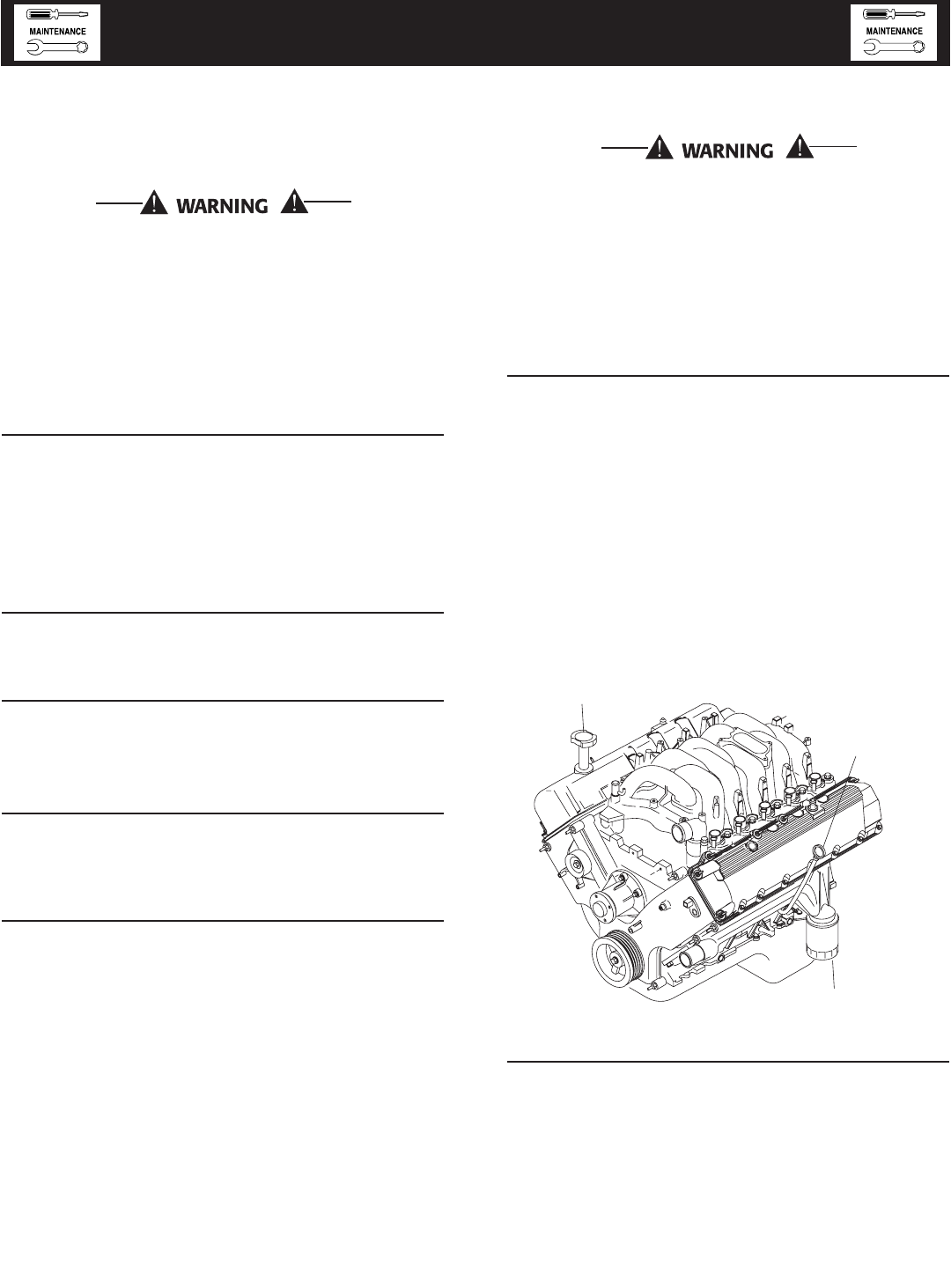
CHECK ENGINE OIL
Check engine crankcase oil level (Figure 10.1) at least
every 20 hours of operation, or prior to use.
• Remove oil dipstick and wipe dry with a clean, lint-
free cloth.
• Install oil dipstick, then remove again.
• Oil should be between FULL and ADD marks.
• If oil level is below the dipstick ADD mark,
remove oil fill cap. Add the recommended oil to
bring oil level up to the FULL mark. DO NOT
FILL ABOVE THE “FULL” MARK. See “Engine Oil
Recommendations” for recommended oils.
Figure 10.1 - Oil Dipstick and Oil Fill Cap
Oil Filter
Oil Fill
Oil
Dipstic
k
BATTERY FLUID
Check battery electrolyte fluid at least once weekly.
Fluid should cover separators in all battery cells. If
fluid level is low, add distilled water to cover tops of
separators. DO NOT USE TAP WATER IN BATTERY.
10-1
Standby Generator Sets
Maintenance
Maint004 Rev. 0 08/05
ENGINE COOLANT
Check coolant level in coolant recovery bottle. See the
“Specifications” section.
• Add recommended coolant mixture as necessary.
• Periodically remove radiator pressure cap to make
sure the coolant recovery system is functioning
properly. Coolant should be at bottom of radiator
filler neck. If coolant level is low, inspect gasket in
radiator pressure cap. Replace cap, if necessary.
To have pressure cap tested, contact an Authorized
Service Dealer. Inspect cooling system and coolant
recovery system for leaks.
MAINTENANCE OWNER/
OPERATOR CAN PERFORM
CHECK ENGINE OIL LEVEL
Refer to the “Checking Fluid Levels” section.
CHECK BATTERY
• Check battery fluid level each week as outlined
under “Check Fluid Levels”.
• Check battery cables for condition, tightness, cor-
rosion or damage. Clean, tighten or replace as
necessary.
EXERCISE SYSTEM
Start the generator engine at least once every seven
days and let it run at least 20 minutes. See the
“Weekly Exercise Cycle” section.
INSPECT COOLING SYSTEM
• Inspect engine cooling system at least once each
month.
• Check hoses for damage, deterioration, leaks, etc.
Correct any discrepancies found.
• Check hose clamps for tightness.
CHECK ENGINE COOLANT LEVEL
See the “Checking Fluid Levels” section.
PERFORM VISUAL INSPECTION
Complete a thorough visual inspection of the entire
engine-generator monthly. Look for obvious damage,
loose, missing or corroded nuts, bolts and other fas-
teners. Look for fuel, oil or coolant leaks.
INSPECT EXHAUST SYSTEM
Inspect the exhaust system at least once every three
months. Check all exhaust system pipes, mufflers,
clamps, etc. for condition, tightness, leaks, security,
damage.
CHECK FAN BELT
• Inspect fan belts every three months. Replace any
damaged, deteriorated, worn or otherwise defec-
tive belt.
• Check fan belt tension. Thumb pressure, exerted
midway between pulleys, should deflect about 3/8
to 5/8 inch. Adjust belt tension as required.
INSPECT ENGINE GOVERNOR
Visually inspect electronic governor.
DANGER
Do not attempt to adjust the governor. Only
qualified service facilities should adjust the gov-
ernor. Excessively high operating speeds are dan-
gerous and increase the risk of personal injury.
Low speeds impose a heavy load on the engine
when adequate engine power is not available
and may shorten engine life. Correct rated fre-
quency and voltage are supplied only at the
proper governed speed. Some connected electri-
cal load devices may be damaged by incorrect
frequency and/or voltage. Only qualified service
technicians should adjust the governed speed.
CHANGING ENGINE OIL
Refer to maintenance performed by authorized ser-
vice facilities for engine oil and filter change frequen-
cies.
Drain the oil while the engine is still warm from run-
ning. This means warm up the engine, shut it down
and drain immediately as follows:
1. Remove OIL DRAIN HOSE from its retaining
clip.
2. Loosen and remove OIL DRAIN HOSE CAP. Drain
oil completely into suitable container.
3. When all oil has drained, install and tighten OIL
DRAIN HOSE CAP, and re-install into its retaining
clip.
4. Turn OIL FILTER (Figure 10.2) counterclockwise
and remove. Dispose of old filter.
5. Apply light coating of new engine oil to seal of new
oil filter.-Install FILTER and tighten by hand only.
DO NOT OVERTIGHTEN.
6. Remove OIL FILL CAP. Add recommended oil (see
SPECIFICATIONS). DO NOT FILL ABOVE THE
DIPSTICK “FULL” MARK. Crankcase oil capacity
is 4.0 U.S. quarts (3.8 liters).
After refilling the crankcase with oil, always
check oil level on dipstick. NEVER OPERATE
ENGINE WITH OIL BELOW THE DIPSTICK “ADD”
MARK.
Standby Generator Sets
Maintenance
10-2
Maint004 Rev. 0 08/05
7. Start engine and check for oil leaks.
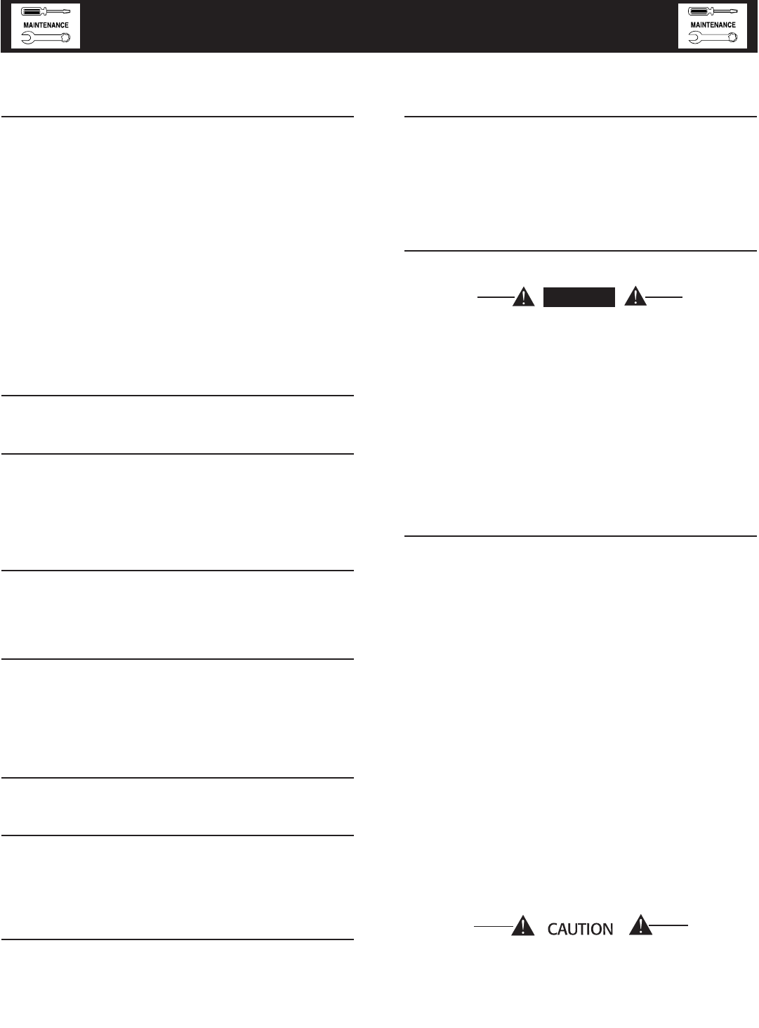
Figure 10.2 - Oil Filter
Oil Filter
Oil Fill
Oil
Dipstic
k
CHANGING THE ENGINE AIR CLEANER
To replace the engine air cleaner, (part number
0A4637), remove the air cleaner cover and replace
the air filter making sure it is positioned properly
before reattaching the cover.
Figure 10.3 — Engine Air Filter
Air Filter
See the “Service Schedule” section for air cleaner
maintenance.
SPARK PLUGS
Reset the spark plug gap or replace the spark plugs
as necessary.
1. Clean the area around the base of the spark plugs
to keep dirt and debris out of the engine. Clean
by scraping or washing using a wire brush and
commercial solvent. Do not blast the spark plugs
to clean.
2. Remove the spark plugs and check the condition.
Replace the spark plugs if worn or if reuse is
questionable. See the “Service Schedule” section
for recommended inspection.
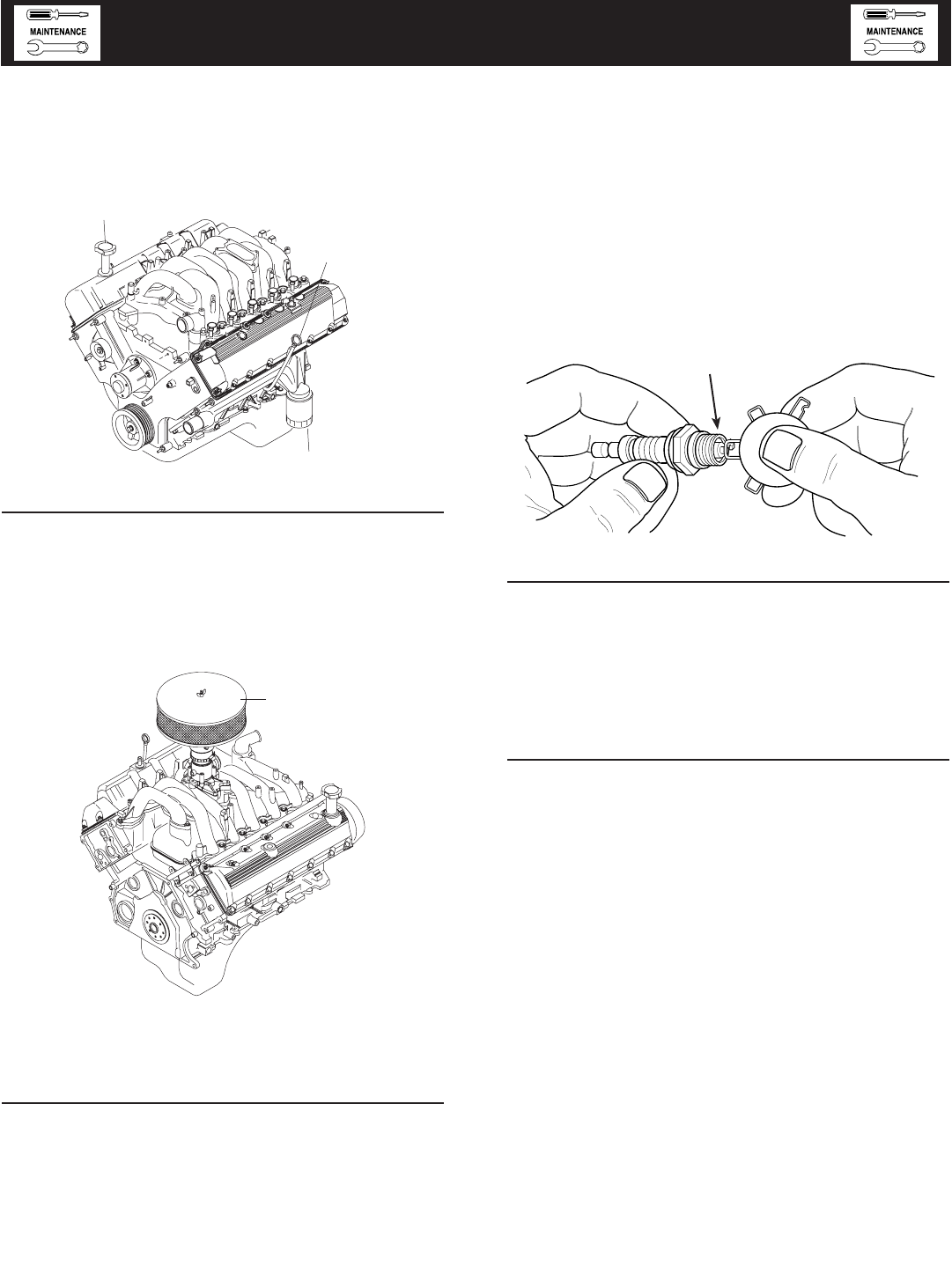
3. Check the spark plug gap using a wire feeler
gauge. Adjust the gap to 1.14 mm (0.045 inch)
by carefully bending the ground electrode (Figure
10.4).
Figure 10.4 – Setting the Spark Plug Gap
COOLANT CHANGE
Every year, have an Authorized Service Facility
drain, flush and refill the cooling system. See the
“Specifications” section for cooling system recom-
mendations.
MISCELLANEOUS MAINTENANCE
CLEANING THE GENERATOR
Keep the generator as clean and as dry as possible.
Dirt and moisture that accumulates on internal gen-
erator windings have an adverse effect on insulation
resistance.
Periodically clean generator exterior surfaces. A soft
brush may be used to loosen caked on dirt. Use a
vacuum system or dry, low pressure air to remove
any accumulations of dirt. The generator is housed
inside an all-weather enclosure, clean the enclosure
with a soft, damp cloth or sponge and water.
Once each year, have the generator cleaned and
inspected by an Authorized Service Dealer. That
dealer will use dry, low pressure air to clean internal
windings. Parts inside the control console should be
cleaned and inspected at this time as well.
Finally, have the insulation resistance of stator and
rotor windings checked. If insulation resistances are
excessively low, the generator may require drying.
SET PLUG GAP AT 1.14 mm
(0.045 inch)
Standby Generator Sets
Maintenance
10-3
Maint004 Rev. 0 08/05
BATTERY
All lead-acid storage batteries discharge when not in
use. Refer to specific instructions and warnings that
accompany the battery. If such information is not
available, observe the following precautions when
handling a battery:
• DO NOT use jumper cables and a booster battery
to crank or start the generator engine.
• DO NOT recharge a weak battery while it is
installed in the generator. Remove battery from
generator and recharge in a well-ventilated area,
away from fuel vapors, sparks, heat or flames.
• Battery electrolyte fluid is an extremely caustic
sulfuric solution that can cause severe burns. DO
NOT permit fluid to contact eyes, skin, clothing,
painted surfaces, wiring insulation, etc. If any bat-
tery fluid is spilled, flush the affected area with
clear water immediately.
• Always wear safety glasses, rubber apron and
gloves when handling a battery.
• Batteries give off explosive hydrogen gas while
charging. The gas can form an explosive mixture
around the battery for several hours after charging.
Any spark, heat or flames can ignite the gas and
cause an explosion which can shatter the battery,
causing blindness or other serious injury.
BATTERY MAINTENANCE
The battery should be inspected per the “Service
Schedule” section. The following procedure should
be followed for inspection:
1. Inspect the battery posts and cables for tightness
and corrosion. Tighten and clean as necessary.
2. Check the battery fluid level of unsealed batteries
and, if necessary, fill with DISTILLED WATER
ONLY. DO NOT USE TAP WATER IN BATTER-
IES.
3. Have the state of charge and condition checked.
This should be done with an automotive-type bat-
tery hydrometer.
DANGER
Storage batteries give off explosive hydrogen
gas. This gas can form an explosive mixture
around the battery for several hours after charg-
ing. The slightest spark can ignite the gas and
cause an explosion. Such an explosion can shat-
ter the battery and cause blindness or other
injury. Any area that houses a storage battery
must be properly ventilated. Do not allow smok-
ing, open flame, sparks or any spark producing
tools or equipment near the battery.
Battery electrolyte fluid is an extremely caus-
tic sulfuric acid solution that can cause severe
burns. Do not permit fluid to contact eyes, skin,
clothing, painted surfaces, etc. Wear protective
goggles, protective clothing and gloves when
handling a battery. If the fluid is spilled, flush
the affected area immediately with clear water.
Do not use any jumper cables or booster battery
to crank and start the generator engine. If the
battery has completely discharged, remove it
from the generator for recharging.
Be sure the AUTO/OFF/MANUAL switch is set to
the OFF position before connecting the battery
cables. If the switch is set to AUTO or MANUAL,
the generator can crank and start as soon as the
battery cables are connected.
Be sure the 120VAC power supply to the battery
is turned OFF, or sparking may occur at the bat-
tery posts as the cables are attached and cause
an explosion.
BATTERY REPLACEMENT
When replacing batteries, use the same number and
the type of battery that follows:
NOTE:
The BCI number should be located directly on the
battery.
REPAIR PARTS
The latter portion of this manual consists of exploded
views, parts lists and electrical data pertaining to this
generator set. The parts lists consist of (a) an item
number, (b) a part number, (c) the quantity required,
and (d) a description of the part. The item number
corresponds to an identical number on the exploded
view drawing.
BCI Group No. CCA
24F-6 525 @ 0 deg. F
Standby Generator Sets
Maintenance
10-4
Maint004 Rev. 0 08/05

SERVICE SCHEDULE
30 KW - 150 KW STANDBY GAS ENGINE DRIVEN GENERATOR SETS
The following is a recommended maintenance schedule for standby gas engine driven generator sets from 30kW to
150 kW in size. The established intervals in the schedule are the maximum recommended when the unit is used
in an average service application. They will need to be decreased (performed more frequently) if the unit is used
in a severe application. Use calendar time, from the previous maintenance interval to determine the next required
maintenance interval.
Service Maintenance Interval Information:
The various service maintenance intervals are designated by interval numbers as follows:
1 An early inspection of the generator set to insure it is ready to operate when required and to identify any poten-
tial problem areas.
This inspection may be performed by the end user providing the following safety steps are taken to prevent
the engine from starting automatically without warning:
To prevent injury, perform the following steps in the order indicated before starting any maintenance:
• Disable the generator set from starting and/or connecting to the load by setting the control panel Auto/Off/
Manual switch to the “OFF” position.
• Remove the 15 amp control panel fuse.
• Turn off the battery charger.
• Remove the negative battery cable.
The battery charger must be turned off BEFORE removing the battery cable to prevent an over current condition
from burning out sensitive control panel components and circuits.
Following all maintenance, reverse these steps to insure the unit is returned to standby setup for normal
operation when required.
2 A wear-in service inspection of the generator set to insure it is ready to operate and carry the load when
required, and to identify any potential problem areas.
Performed ONLY ONCE following the first three months or the first 30 hours of operation after purchase of
the unit.
This inspection contains some maintenance tasks which require special tools, equipment, and/or knowledge
to accomplish and should be performed only by an Authorized Service Dealer.
3 An operational inspection of the generator set to insure it is ready to operate and carry the load when required,
and to identify any potential problem areas.
Performed semi-annually or following each 50 hours of operation of the unit.
This inspection contains some maintenance tasks which require special tools, equipment, and/or knowledge
to accomplish and should be performed only by an Authorized Service Dealer.
4 A mid-level inspection of the generator set to insure it is ready to operate and carry the load when required,
and to identify any potential problem areas.
Performed annually or following each 100 hours of operation of the unit.
This inspection contains some maintenance tasks which require special tools, equipment, and/or knowledge
to accomplish and should be performed only by an Authorized Service Dealer.
5 A comprehensive inspection of the generator set to insure it is properly serviced and ready to operate and carry
the load when required, and to identify any potential problem areas.
Performed annually or following each 250 hours of operation of the unit.
This inspection contains some maintenance tasks which require special tools, equipment, and/or knowledge
to accomplish and should be performed only by an Authorized Service Dealer.
11-1
Standby Generator Sets
Service Schedule
SrvSchd001 Rev. A 09/05
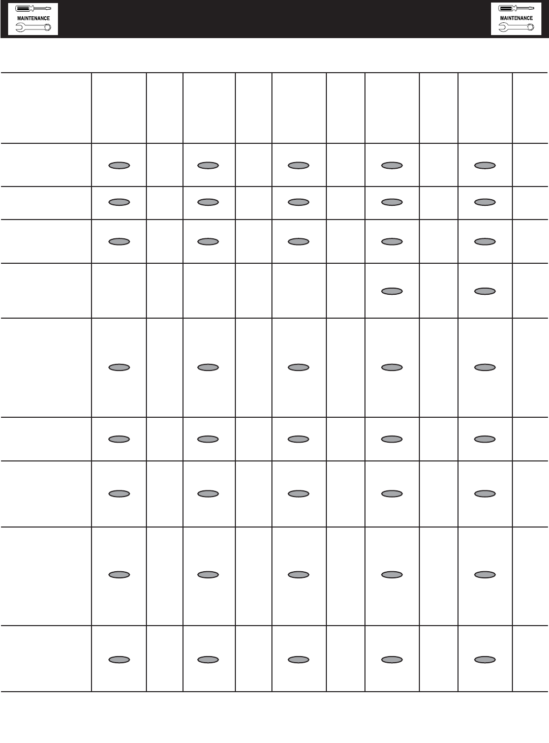
Maintenance Level 1 Level 2 Level 3 Level 4 Level5
Tasks Recom- Task Required Task Required Task Task Required Task
mended Comp. to be done Comp. to be done Comp. Required Comp. to be done Comp.
to be done (Date- 3 months/ (Date- Semi- (Date- to be done (Date- Bi- (Date-
monthly/ Initials) Break-in Initials) annually/ Initials) Annually/ Initials) annually/ Initials)
10 hrs. 30 hrs. 50 hrs. 100 hrs. 250 hrs.
1. Disable the unit
from operating
per the first page
warning.
2. Check the engine
oil level. Adjust
as necessary.
3. Check the engine
coolant level.
Adjust as
necessary.
4. Check the engine
coolant thermal
protection level.
Correct as
necessary.
5. Check the natural
gas delivery
system for leaks
and correct
pressure on gas
engine driven
units. Tighten
connections as
necessary.
6. Check the air
inlets and outlets
for debris. Clean
as necessary.
7. Check the battery
electrolyte level
and specific
gravity if
accessible. Adjust
as necessary.
8. Check the battery
posts, cables,
and charger for
loose
connections,
corrosion, and
proper operation.
Correct as
necessary.
9. Check the unit
wiring for loose
connections,
corrosion, and
damage. Correct
as necessary.
11-2
Standby Generator Sets
Service Schedule
SrvSchd001 Rev. A 09/05
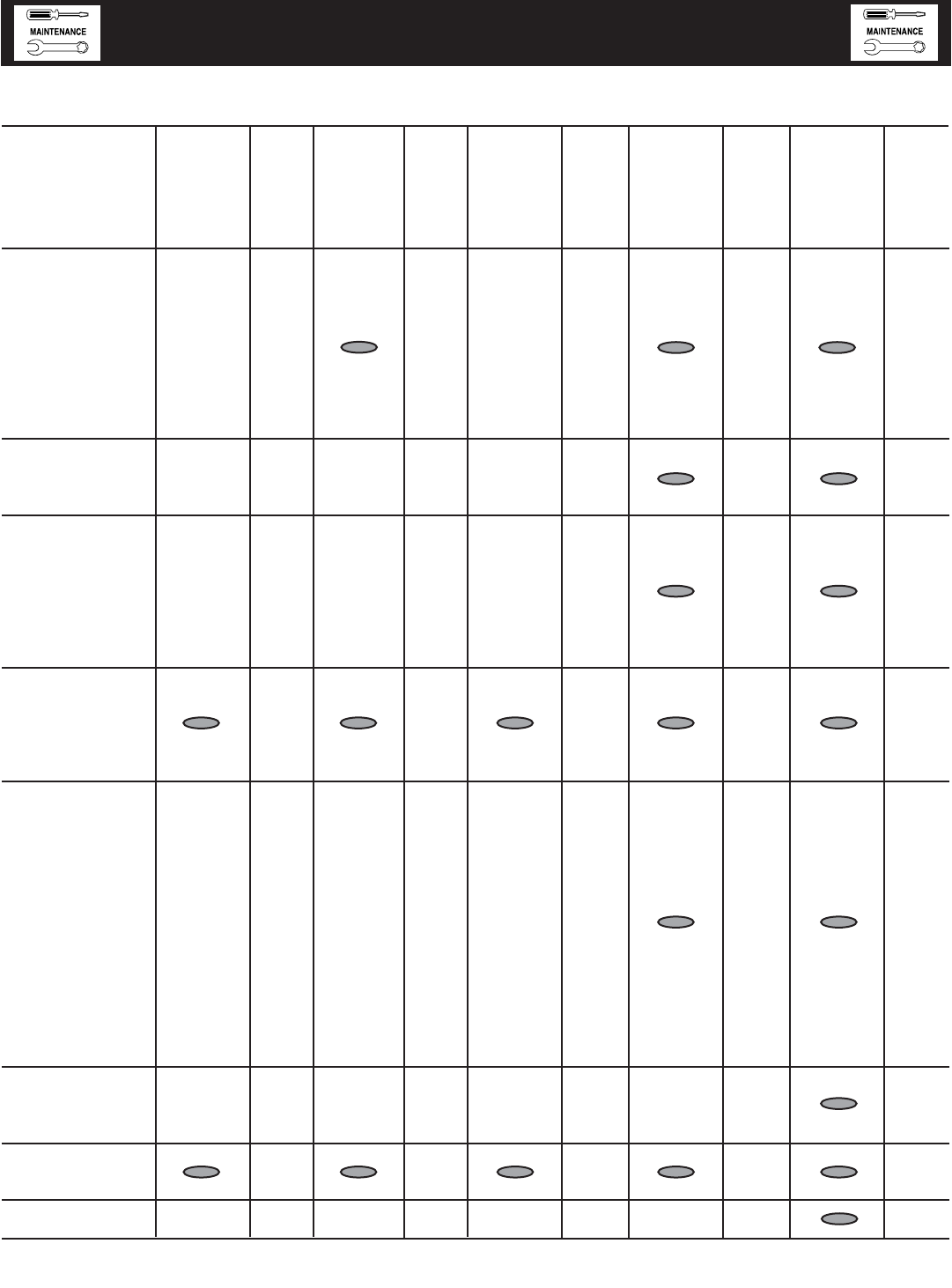
Maintenance Level 1 Level 2 Level 3 Level 4 Level5
Tasks Recom- Task Required Task Required Task Task Required Task
mended Comp. to be done Comp. to be done Comp. Required Comp. to be done Comp.
to be done (Date- 3 months/ (Date- Semi- (Date- to be done (Date- Bi- (Date-
monthly/ Initials) Break-in Initials) annually/ Initials) Annually/ Initials) annually/ Initials)
10 hrs. 30 hrs. 50 hrs. 100 hrs. 250 hrs.
10. Check the engine
accessory drive
belts and fan
coupling device
if equipped for
correct tension,
wear, weather
cracking, and
damage. Replace
as necessary.
11. Check the engine
valve clearance.
Adjust as
necessary.
12. Visually inspect
the unit looking
for leaks, wear or
damage, loose
connections or
components, and
corrosion. Correct
as necessary.
13. Test the engine
and transfer
switch safety
devices. Correct
and/or adjust as
necessary.
14. Initiate an
automatic start
and transfer of
the unit to site
load and exercise
it for at least 1
hour looking for
leaks, loose
connections or
components, and
abnormal
operating
conditions.
Correct as
necessary.
15. Replace the
engine
accessory
drive belts.
16. Check gearbox
oil level (if
equipped).
17. Change gearbox
oil (if equipped).
11-3
Standby Generator Sets
Service Schedule
SrvSchd001 Rev. A 09/05
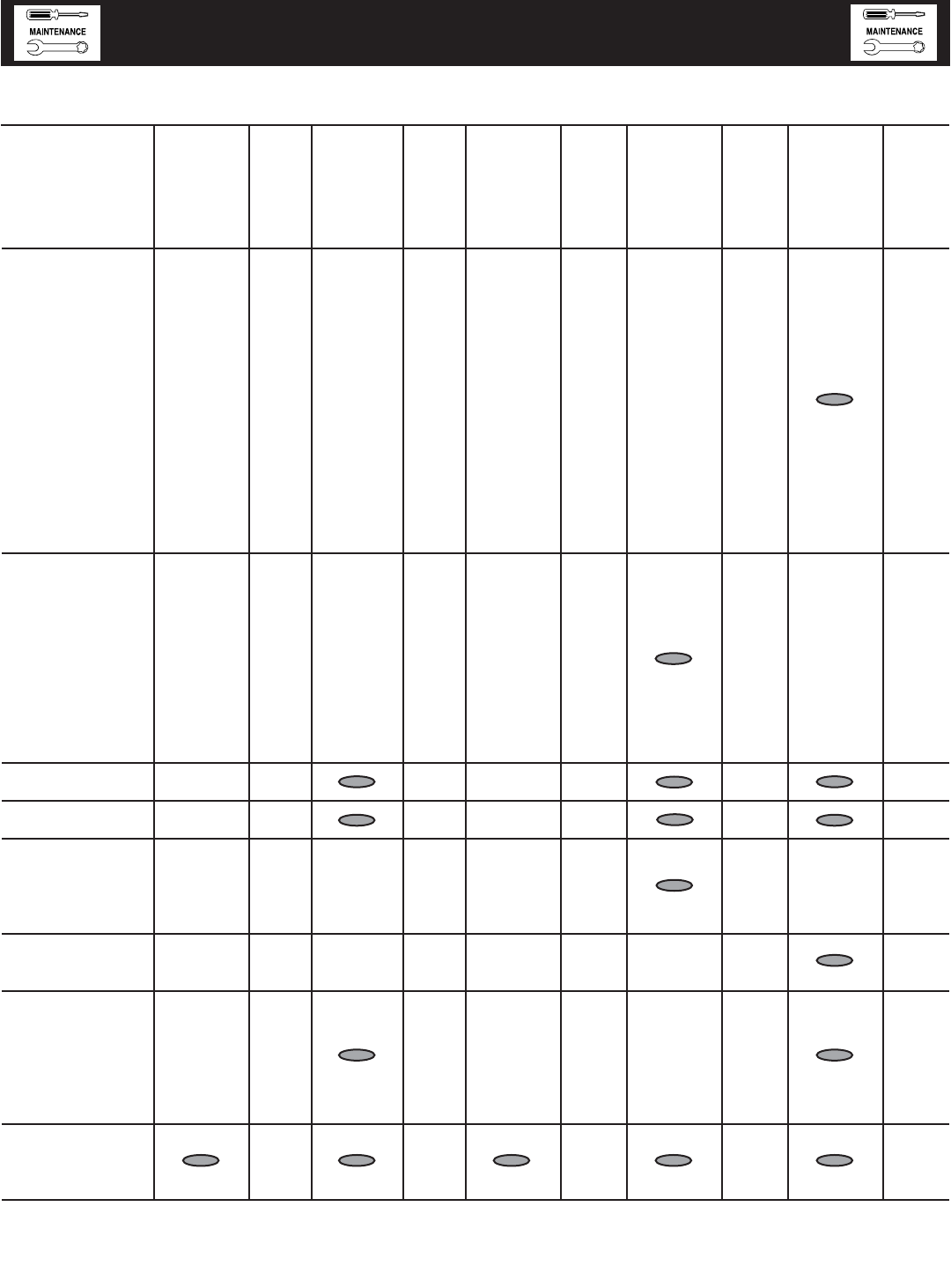
Maintenance Level 1 Level 2 Level 3 Level 4 Level5
Tasks Recom- Task Required Task Required Task Task Required Task
mended Comp. to be done Comp. to be done Comp. Required Comp. to be done Comp.
to be done (Date- 3 months/ (Date- Semi- (Date- to be done (Date- Bi- (Date-
monthly/ Initials) Break-in Initials) annually/ Initials) Annually/ Initials) annually/ Initials)
10 hrs. 30 hrs. 50 hrs. 100 hrs. 250 hrs.
18. Start and
exercise the unit
at full rated load
(use a load bank
if the site load is
not enough) for
at least 2 hours
looking for leaks,
loose
connections or
components, and
abnormal
operating
conditions.
Correct as
necessary.
19. Perform an
engine oil
analysis (send a
sample to a lab
for results).
Change the
engine oil and
filters if the
analysis results
indicate this is
required.
20. Change the
engine oil.
21. Replace the
engine oil filter(s).
22. Replace engine
spark plugs.
Clean and re-gap
or replace as
necessary.
23. Replace the
engine air
filter(s).
24. Perform a 5
minute no-load
operational run
of the unit
looking for any
post service
problems.
25. Return the unit
to standby setup
for operation
when required.
11-4
Standby Generator Sets
Service Schedule
SrvSchd001 Rev. A 09/05

TROUBLESHOOTING GUIDE
PROBLEM CAUSE CORRECTION
Engine won’t crank. 1. 15 amp fuse blown. 1. Replace fuse.
2. Loose or corroded or defective 2. Tighten, clean or replace
battery cables. battery cables as necessary.
3. Defective starter contactor. 3. Replace contactor.*
4. Defective starter motor. 4. Replace starter motor.*
5. Dead or Defective Battery. 5. Remove, change or replace battery.
6. 5 amp fuse blown. 6. Replace fuse.*
Engine cranks but won't start 1. Out of fuel. 1. Replenish fuel.
2. Fuel solenoid (FS) is defective 2. Replace solenoid.*
3. Open Wire #14A from Engine Control 3. Reconnect wire.
circuit board.
4. Spark plugs defective. 4. Clean, regap or replace plugs.
5. Door on tank not closed. 5. Close door on tank.
Engine starts hard, runs rough. 1. Flame arrestor (air cleaner) plugged or 1. Clean or replace as needed.
damaged.
2. Plugged fuel line. 2. Unclog fuel line.
3. Defective spark plugs. 3. Clean, regap or replace plugs.
4. Fuel pressure incorrect. 4. Confirm fuel pressure to regulator is as
recommended in SPECIFICATIONS.
Engine starts then shuts down. 1. Engine oil level is low. 1. Check oil and add oil as needed.
2. Engine is overheated. 2. Check cooling system for leaks.
3. Defective Low Oil Pressure Switch 3. Replace switch.*
4. Defective Coolant Temperature Switch 4. Replace switch.*
5. Defective Control Module circuit board. 5. Replace board.*
6. Coolant Level is Low. 6. Repair leak - Add coolant.
7. Defective Low Coolant Level Switch 7. Replace Switch.*
AUTO/OFF/MANUAL Switch at OFF, 1. Defective AUTO/OFF/MANUAL switch 1. Replace switch.*
engine continues to run 2. Open/disconnected wire #15A between 2. Reconnect/close wire.
AUTO/OFF/MANUAL switch and Control
Module circuit board.
3. Defective Control Module circuit board 3. Replace board.*
No AC output from generator. 1. Check main line circuit breaker. 1. Reset to ON or CLOSED.
2. Check circuit breaker & fuses. 2. Reset and replace, if necessary.
3. Transfer switch set to NORMAL position 3. Set to GENERATOR position.
4. Generator internal failure. 4. *
5. Thermal circuit breaker open. 5. Auto-reset - Wait 5 min. and
attempt restart.
*Contact the nearest Authorized Dealer for assistance.
12-1
Standby Generator Sets
Troubleshooting
Trblsht001 Rev. 0 08/05

Standby Generator Sets
Notes

Standby Generator Sets
Notes

Standby Generator Sets
Notes

Standby Generator Sets
Notes
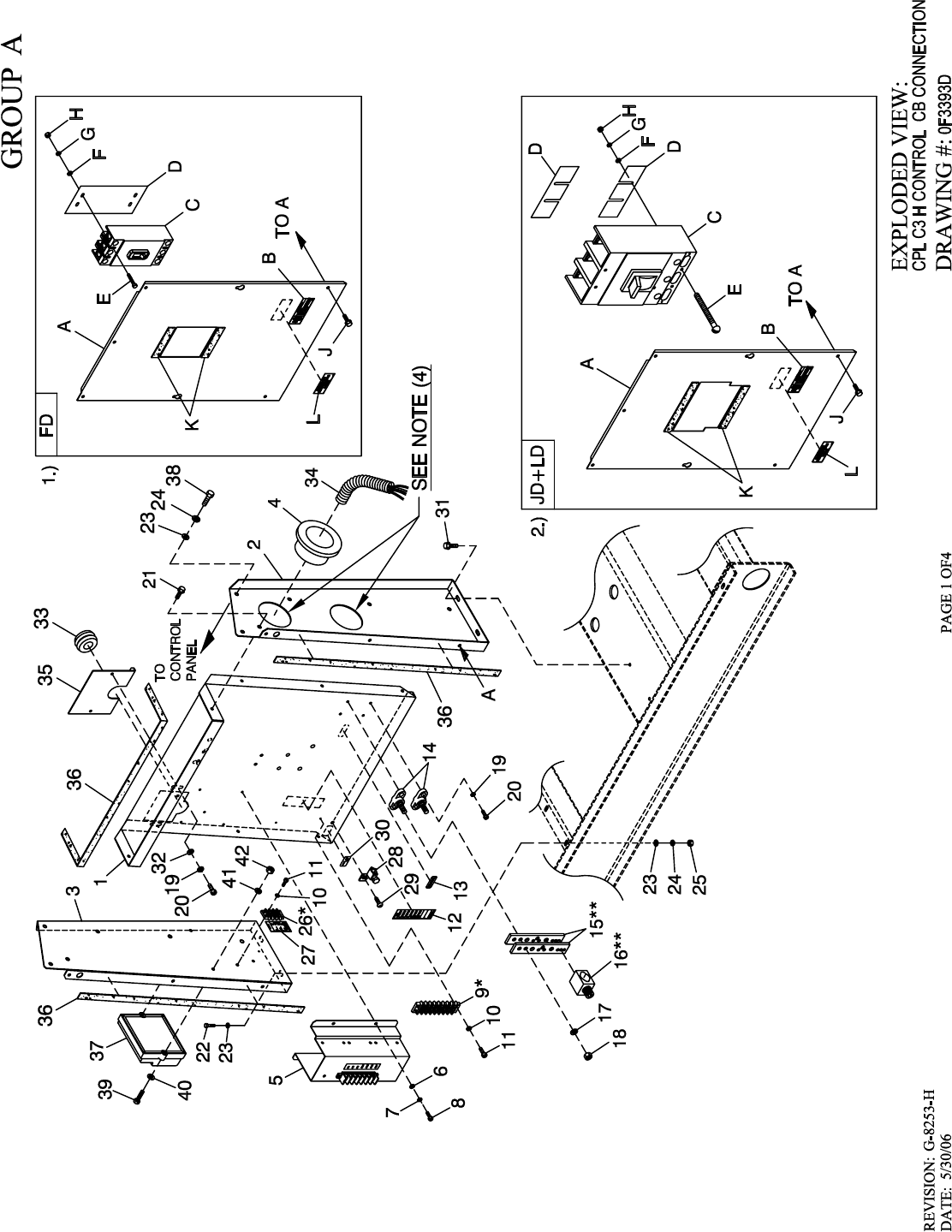
1 0F2885 1 PANEL CB CONN BOX
2 0F2883 1 STAND RH CONTROL
0F9637 (4) 1 STAND RH CONTROL, TWO HOLE (FOR 5.4L 100KW &
4.6L 80KW 1PHASE)
3 0F3685 1 STAND LH CONTROL C5 GRBX
4 023484N 1 BUSHING SNAP SB-2.5-31
023484N 2 BUSHING SNAP SB-2.5-31 (FOR 5.4L 100KW & 4.6L
80KW 1PHASE)
5 086961 1 INTERFACE 1PH 240V
067617030A - INTERFACE 3PHS 416/480V
067617030B - INTERFACE 3PHS 208/240V
6 043180 4 WASHER FLAT M4
7 022264 4 WASHER LOCK #8-M4
8 0C3990 4 SCREW PHTT M4-0.7 X 10 ZYC
(1) 9 057701 REF. BLOCK TERM 20A 8 X 6 X 1100V
10 022155 2 WASHER LOCK #6
11 0C2428 2 SCREW PHTT #6-32 X 1/2 ZYC
12 0F3618 1 DECAL CPL CUST CONN H CTRL
13 0A9457 1 DECAL NEUTRAL
14 057073 2 JUNCTION BLOCK 3/8-16
(2) 15 0D5466 REF. BUS BAR NEUTRAL BLOCK 390
(2) 16 0A7822 REF. LUG SLDLSS 600/250-1/0 X 1/4-28
17 022237 4 WASHER LOCK 3/8
18 022241 4 NUT HEX 3/8-16 STEEL
19 049226 6 WASHER LOCK M5
20 0C2266 6 SCREW PHTT M5-0.8 X 16 ZYC
21 0C2454 10 SCREW THF M6-1 X 16 N WA Z/JS
22 042568 4 SCREW HHC M6-1.0 X 20 G8.8
23 022473 12 WASHER FLAT 1/4-M6 ZINC
24 022097 8 WASHER LOCK M6-1/4
25 049813 4 NUT HEX M6 X 1.0 G8 YEL CHR
(1) 26 0D4698 1 BLOCK TERM 20A 6 X 3 X 1100V
27 0F4464 1 DECAL CUST CONN 120V UTILITY
28 025433 1 LUG SLDLSS #6-14 X 13/64 CU
29 024469 1 SCREW HHTT #10-32 X 3/8 CZ
30 067210A 1 DECAL GROUND LUG
31 0D6029 4 SCREW HHTT M6-1.0 X 16 ZYC
32 051713 2 WASHER FLAT M5
33 081008 1 GROMMET 1.25 X .25 X .75
34 077043J 3 CONDUIT FLEX 2.0" ID
077043J 4 CONDUIT FLEX 2.0" ID (FOR 5.4L 100KW & 4.6L 80KW
1 PHASE)
35 0F6156 1 PLATE WIRE SNGL GALV
36 029289 1 TAPE ELEC 1/2 FOAM (AS REQ’D)
(3) 37 0F8656 REF ASSY PCB 4.6L IGNITION MODULE
0F3113 REF ASSY PCB HSB CTRL IGN MODULE (ALL OTHER
APPLICATIONS EXCEPT 4.6L G3)
38 047411 4 SCREW HHC M6-1.0 X 16 G8.8
39 036943 2 SCREW PPHM #10/32 X 2
40 023897 2 WASHER FLAT #10 ZINC
41 022152 2 WASHER LOCK #10
42 022158 2 NUT HEX #10-32 STEEL
1.) UL CIRCUIT BREAKER (FD)
A 0F2887 1 COVER FD FRM CB
B 065469 1 DECAL DANGER HIGH VOLTAGE
C 0D5572 - CB 0150A 3P 600V S FD6 LL
0D5573 - CB 0175A 3P 600V S FD6 LL
0D5575 - CB 0225A 3P 600V S FD6 LL
0D5576 - CB 0250A 3P 600V S FD6 LL
D 0F0199 1 INSULATOR CB FD FRAME 30MIL
E 065960 4 SCREW SHC 1/4-20 X 4 G8.8 NZ
F 022473 4 WASHER FLAT 1/4-M6 ZINC
G 022097 4 WASHER LOCK M6-1/4
H 022127 4 NUT HEX 1/4-20 STEEL
J 0C2454 4 SCREW THF M6-1 X 16 N WA Z/JS
K 029289 1 TAPE ELEC 1/2 FOAM (AS REQ’D)
L 0F1733 1 DECAL CUSTOMER CONNECT INSIDE
2.) UL CIRCUIT BREAKER (JD+LD)
A 0F2721 1 COVER CIR BRKR JD/LD
B 065469 1 DECAL DANGER HIGH VOLTAGE
C 0D5577 - CB 0300A 3P 600V S JD6 LL
0D5578 - CB 0350A 3P 600V S JD6 LL
0D5579 - CB 0400A 3P 600V S JD6 LL
0D5581 - CB 0600A 3P 600V S LD6
0D5585 - CB 0450A 3P 600V S LD6 LL
D 0F2353 2 INSULATOR CIRCUIT BR. JD/LD
E 022770 4 SCREW RHM 1/4-20 X 3
F 022473 4 WASHER FLAT 1/4-M6 ZINC
G 022097 4 WASHER LOCK M6-1/4
H 022127 4 NUT HEX 1/4-20 STEEL
J 0C2454 7 SCREW THF M6-1 X 16 N WA Z/JS
K 029289 1 TAPE ELEC 1/2 FOAM (AS REQ’D)
L 0F1733 1 DECAL CUSTOMER CONNECT INSIDE
(1) ITEM INCLUDED WITH HARNESS.
(2) ITEM INCLUDED WITH 0D5464B.
(3) ITEM IS PART OF 9R.
(4) ROUTE ONE SET (11, 22, 33, 44) THROUGH ONE HOLE; AND
ROUTE THE SECOND SET (11, 22, 33, 44) THROUGH THE OTHER
HOLE.
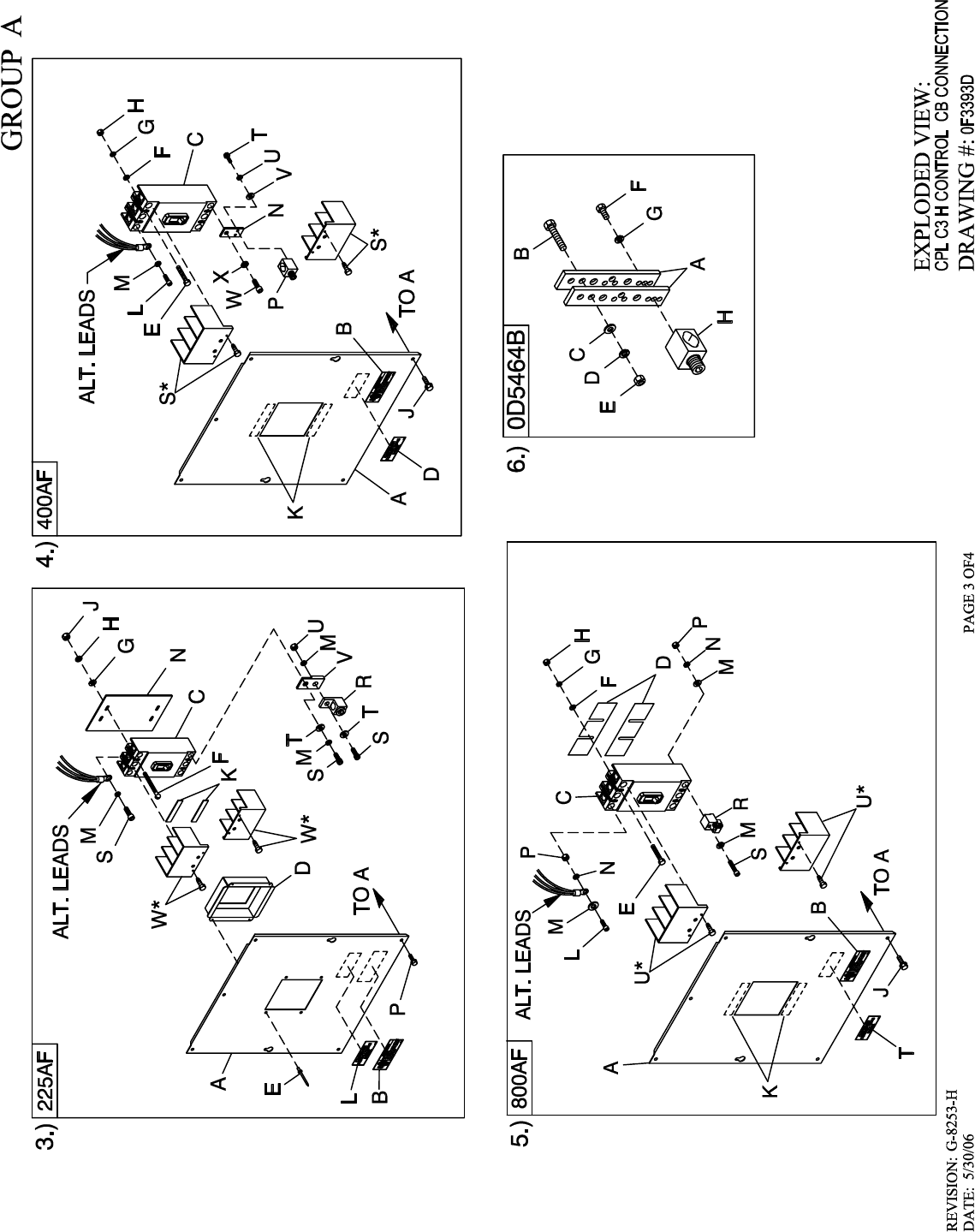
3.) UL CIRCUIT BREAKER (225AF)
A 0F4173 1 COVER CB C5 225AF
B 065469 1 DECAL DANGER HIGH VOLTAGE
C 0F4165$ REF CIRCUIT BREAKERS 200A FRAME
D 0F4186 1 COVER CB DISH 225AF
E 036261 4 RIVET POP .125 X .275 SS
F 053640 4 SCREW RHM #8-32 X 3-1/4
G 038150 4 WASHER FLAT #8 ZINC
H 022264 4 WASHER LOCK #8-M4
J 022471 4 NUT HEX #8-32 STEEL
K 029289 2 TAPE ELEC 1/2 FOAM
L 0F1733 1 DECAL CUSTOMER CONNECT INSIDE
M 022129 9 WASHER LOCK M8-5/16
N 0F8432 1 INSULATOR CB 225AF
P 0C2454 7 SCREW THF M6-1 X 16 N WA Z/JS
R 0F8451 3 LUG SLDLSS 300 MCM-6 AL/CU
S 049897 9 SCREW SHC M8-1.25 X 20 G8
T 022145 6 WASHER FLAT 5/16-M8 ZINC
U 045771 3 NUT HEX M8-1.25 G8 CLEAR ZINC
V 0F8843 3 BUS BAR 200A LUG ADAPTOR
(1) W W/CB 2 TERMINAL COVER CB
4.) UL CIRCUIT BREAKER (400AF)
A 0F4175 1 COVER CB C5 400AF
B 065469 1 DECAL DANGER HIGH VOLTAGE
C 0F4166$ REF CIRCUIT BREAKERS 400A FRAME
D 0F1733 1 DECAL CUSTOMER CONNECT INSIDE
E 042419 4 SCREW RHM 10-32 X 4
F 023897 4 WASHER FLAT #10 ZINC
G 022152 4 WASHER LOCK #10
H 022158 4 NUT HEX #10-32 STEEL
J 0C2454 7 SCREW THF M6-1 X 16 N WA Z/JS
K 029289 1 TAPE ELEC 1/2 FOAM
(2) L 052647 2/3 SCREW SHC M10-1.5 X 25 G12.9
(2) M 046526 2/3 WASHER LOCK M10
N W/CB 3 BUS BAR CB ADAPTER 225-400 A
P 0A7822 3 LUG SLDLSS 600/250-1/0 X 1/4-28
R 022131 3 WASHER FLAT 3/8-M10 ZINC
(1) S W/CB 2 TERM COVER CB
T 023334 6 SCREW HHC 1/4-28 X 1/2 G5
U 022097 6 WASHER LOCK M6-1/4
V 022473 6 WASHER FLAT 1/4-M6 ZINC
(2) W W/CB 2/3 SCREW SHC M10-1.5 X 25 G12.9
(2) X W/CB 2/3 WASHER LOCK M10
5.) UL CIRCUIT BREAKER (800AF)
A 0F4176 1 COVER CB C5 800AF
B 065469 1 DECAL DANGER HIGH VOLTAGE
C 0F4167$ REF CIRCUIT BREAKERS 800A FRAME
D 0F8433 2 INSULATOR CB 800AF
E 024196 4 SCREW RHM 1/4-20 X 3-1/2
F 022473 4 WASHER FLAT 1/4-M6 ZINC
G 022097 4 WASHER LOCK M6-1/4
H 022127 4 NUT HEX 1/4-20 STEEL
J 0C2454 7 SCREW THF M6-1X16 N WA Z/JS
K 029289 2 TAPE ELEC 1/2 FOAM
L 060619 3 SCREW SHC M10-1.50 X 40 G12.9
M 022131 9 WASHER FLAT 3/8-M10 ZINC
N 022237 6 WASHER LOCK 3/8
P 045772 6 NUT HEX M10-1.5 G8 YEL CHR
R 0F8452 3 LUG SLDLSS 500-750 X 2 MCM AL/CU
S 097950 3 SCREW SHC M10-1.25 X 70 G8.8
T 0F1733 1 DECAL CUSTOMER CONNECT INSIDE
(1) U W/CB 2 TERM COVER VITZROTECH 400AF CB
6.) NEUTRAL BLOCK 390 / 200-400A
A 0D5466 2 BUS BAR NEUTRAL BLOCK 390
B 039287 1 SCREW HHC M8-1.25 X 45 G8.8 FT
C 022145 1 WASHER FLAT 5/16-M8 ZINC
D 022129 1 WASHER LOCK M8-5/16
E 045771 1 NUT HEX M8-1.25 G8 YEL CHR
F 045335 2 SCREW HHC 1/4-28 X 3/4 G5
G 022097 2 WASHER LOCK M6-1/4
H 0A7822 1 LUG SLDLSS 600/250-1/0X1/4-28
(1) HARDWARE FOR MTG. CB TERMINAL COVERS IS SUPPLIED
WITH CIRCUIT BREAKERS.
(2) 2/3 QTY. 2POLE & 3 POLE CB.
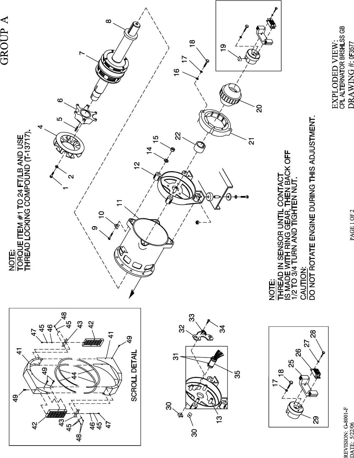
1 055173 6 SCREW HHC M8-1.25 X 20 G10.9
2 022129 6 WASHER LOCK M8-5/16
4 0E2747A 1 FAN SAE ALTERNATOR (G/B)
5 0A3870 1 KEY SQ 3/8 X 1-9/16 STEEL
6 0A3009 1 HUB DRIVE 390 SAE GB
7 0F5564D 1 RTR 390 100KB3 GB SAE TECHUM
0F5563D 1 RTR 390 130KB4 GB SAE TECHUM
0A3881D 1 RTR 390 80GB BR BRLSS
0A3881B 1 RTR 390 80GB 1P BRLSS
0A3882B 1 RTR 390 100GB 1P BRLSS
0A3883B 1 RTR 390 125GB 1P BRLSS
8 * 052624 1 BEARING BALL 6212 SEALED
9 0A5580 4 SCREW HHC M14-2.0 X 140 G8.8
10 0A1633 4 WASHER 390 SAE ALT.
11 0F7351 1 STR 390 130 GB4 CPL
0F7349 1 STR 390 80 AB3 CPL
0F7348 1 STR 390 100 AB3 CPL
0F7350 1 STR 390 130 AB4 CPL
12 068113 1 CARRIER REAR BRG 15"
13 022392 2 PIN DOWEL 1/2 X 1-1/4
14 043123 4 WASHER LOCK M14
15 051779 4 NUT HEX M14-2.0 G8 YEL CHR
16 052259 2 WASHER FLAT M12
17 051769 3 WASHER LOCK M12
18 068406 3 SCREW HHC M12-1.75 X 60 G10.9
19 072878 1 KEY SQ 3/8 X 3-1/4 STEEL
20 087272 1 ASSY EXCITER 2.00" STK
21 068405C 1 EXITER FIELD 2" LG SPD CONN
22 092950 1 COLLAR SLIP FIT 390 MM
25 090063 1 BRIDGE SUPPORT DIODE 15"
26 090152 1 ASSY BRIDGE RECTIFIER
27 023365 3 WASHER SHAKEPROOF INT #8
28 033143 2 SCREW HHM #8-32 X 7/8
29 090064 1 CAP END ROTOR 390MM
30 083485 2 PLATE NUT
31 031980 2 TIE WRAP UL 14.6 X .14 NATL
32 083401 1 BRACKET-STATOR WIRE
33 042561 1 CLAMP HOSE #36 1.88-2.7
34 033212 2 SCREW HHC 5/16-18 X 1-1/4 G5
35 083549 1 SLEEVE RUBBER
40 0A4089 1 ASSY SCROLL 390 SAE
KIT PARTS I/N’S: 41 THRU 49
41 0A2491 2 SHROUD ALT SHEET METAL
42 0A2497 2 SCREEN SHROUD SAE
43 0A2496 2 BRKT TENSIONER SAE SCROLL
44 056326 8.4 FT. TRIM VINYL BLACK 1/8 GP
45 022307 6 WASHER LOCK M6-1/4
46 022473 6 WASHER FLAT 1/4-M6 ZINC
47 045757 2 SCREW HHC M6-1.0 X 25 G8.8
48 047411 4 SCREW HHC M6-1.0 X 16 G8.8
49 0A2110 12 SCREW SWAGE 1/4-20 X 1/2 ZYC
* ROTOR REPLACEMENT PART
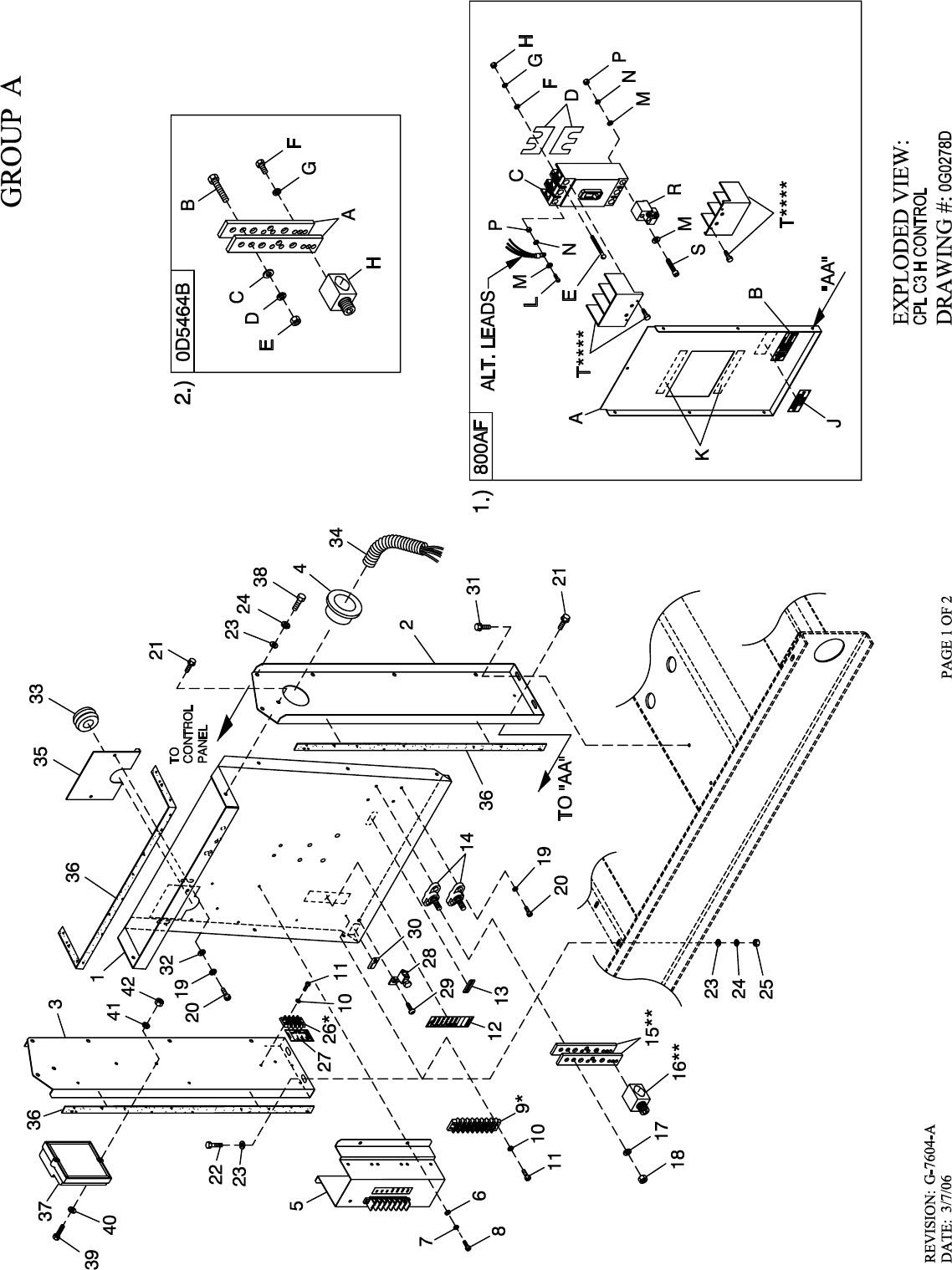
1 0F2885 1 PANEL CB CONN BOX
2 0G0171 1 STAND, RH CONTROL CPL C5
0G0171A 1 STAND RH CONTROL CPL C5 2 HOLE
3 0G0172 1 STAND, LH CONTROL CPL C5
4 023484N 1 BUSHING SNAP SB-2.5-31
5 0F4677 1 ASSY PCB INTERFACE 1PH 240V
067617030A - INTERFACE 3PHS 416/480V
067617030B - INTERFACE 3PHS 208/240V
6 043180 4 WASHER FLAT M4
7 022264 4 WASHER LOCK #8-M4
8 0C3990 4 SCREW PHTT M4-0.7 X 10 ZYC
9 * 057701 REF. BLOCK TERM 20A 8 X 6 X 1100V
10 022155 2 WASHER LOCK #6
11 0C2428 2 SCREW PHTT #6-32 X 1/2 ZYC
12 0F3618 1 DECAL CPL CUST CONN H CTRL
13 0A9457 1 DECAL NEUTRAL
14 057073 2 JUNCTION BLOCK 3/8-16
15 ** 0D5466 REF. BUS BAR NEUTRAL BLOCK 390
16 ** 0A7822 REF. LUG SLDLSS 600/250-1/0 X 1/4-28
17 022237 4 WASHER LOCK 3/8
18 022241 4 NUT HEX 3/8-16 STEEL
19 049226 6 WASHER LOCK M5
20 0C2266 6 SCREW PHTT M5-0.8 X 16 ZYC
21 0C2454 10 SCREW THF M6-1 X 16 N WA Z/JS
22 042568 4 SCREW HHC M6-1.0 X 20 G8.8
23 022473 12 WASHER FLAT 1/4-M6 ZINC
24 022097 8 WASHER LOCK M6-1/4
25 049813 4 NUT HEX M6 X 1.0 G8 YEL CHR
26 * 0D4698 1 BLOCK TERM 20A 6 X 3 X 1100V
27 0F4464 1 DECAL CUST CONN 120V UTILITY
28 025433 1 LUG SLDLSS #6-14 X 13/64 CU
29 024469 1 SCREW HHTT #10-32 X 3/8 CZ
30 067210A 1 DECAL GROUND LUG
31 0D6029 4 SCREW HHTT M6-1.0 X 16 ZYC
32 051713 2 WASHER FLAT M5
33 081008 1 GROMMET 1.25 X .25 X .75
34 077043J 3 CONDUIT FLEX 2.0" ID
35 0F6156 1 PLATE WIRE SNGL GALV
36 029289 1 TAPE ELEC 1/2 FOAM (AS REQ’D)
37*** 0F3113 REF ASSY PCB HSB CTRL IGN MODULE
38 047411 4 SCREW HHC M6-1.0 X 16 G8.8
39 036943 2 SCREW PPHM #10/32 X 2
40 023897 2 WASHER FLAT #10 ZINC
41 022152 2 WASHER LOCK #10
42 022158 2 NUT HEX #10-32 STEEL
1.) UL CIRCUIT BREAKER (800AF)
A 0G0173 1 COVER, CB 803 C5
B 065469 1 DECAL DANGER HIGH VOLTAGE
C 0F4167$ REF CIRCUIT BREAKERS 800A FRAME
D 0F8433 2 INSUL CB 800AF
E 022477 4 SCREW RHM 1/4-20 X 1-1/2
F 022473 4 WASHER FLAT 1/4-M6 ZINC
G 022097 4 WASHER LOCK M6-1/4
H 022127 4 NUT HEX 1/4-20 STEEL
J 0F1733 1 DECAL CUSTOMER CONNECT INSIDE
K 029289 2 TAPE ELEC 1/2 FOAM
L 060619 3 SCREW SHC M10-1.50 X 40 G12.9
M 022131 9 WASHER FLAT 3/8-M10 ZINC
N 022237 6 WASHER LOCK 3/8
P 045772 6 NUT HEX M10-1.5 G8 YEL CHR
R 0F8452 3 LUG SLDLSS 500-750X2 MCM AL/CU
S 0D2576 3 SCREW SHC M10-1.5 X 70 G10.9
T**** W/CB 2 TERM. COVER VITZROTECH 400AF CB
2.) NEUTRAL BLOCK 390 / 200-400A
A 0D5466 1 BUS BAR NEUTRAL BLOCK 390
B 039287 1 SCREW HHC M8-1.25 X 45 G8.8 FT
C 022145 1 WASHER FLAT 5/16-M8 ZINC
D 022129 1 WASHER LOCK M8-5/16
E 045771 1 NUT HEX M8-1.25 G8 YEL CHR
F 045335 2 SCREW HHC 1/4-28 X 3/4 G5
G 083896 2 WASHER LOCK 1/4-M6 SS
H 0A7822 1 LUG SLDLSS 600/250-1/0 X 1/4-28
* ITEM INCLUDED WITH HARNESS
** ITEM INCLUDED WITH 0D5464B
*** ITEM IS PART OF 9R.
**** HARDWARE FOR MTG. CB TERMINAL COVERS IS
SUPPLIED WITH CIRCUIT BREAKERS.
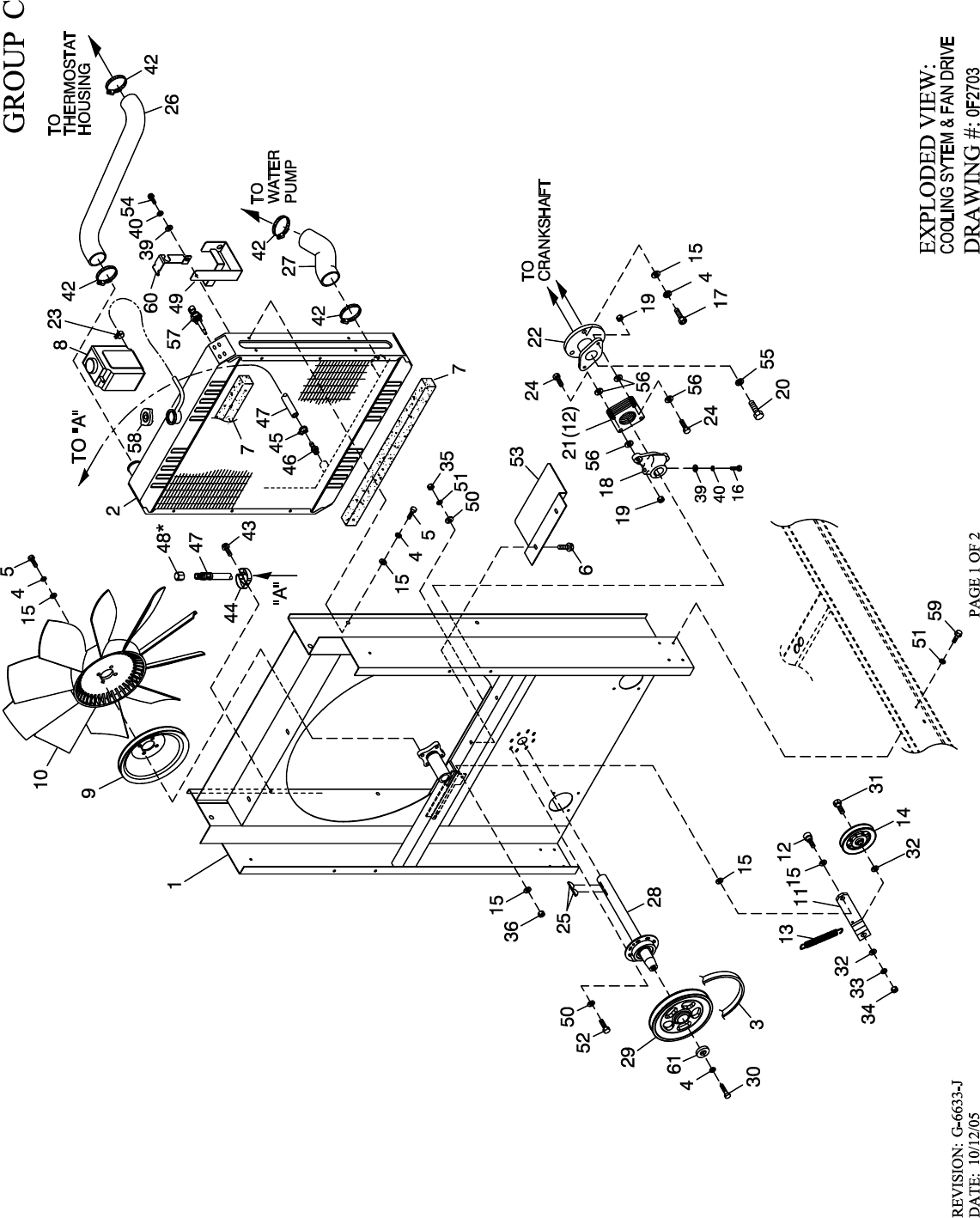
1 0F2687 1 WELDMENT RADIATOR SUPPORT150
2 0F2611 1 RADIATOR 680 X 680 X 70 CPL
3 0F5254 1 V-BELT 31/64" X 62-3/8"
0F5253 1 V-BELT 31/64" X 61-3/8" (5.4L 100KW ONLY)
0F7077 1 V-BELT 1/2" X 63-3/8" (6.8L 100 130KW)
4 046526 12 WASHER LOCK M10
5 051756 8 SCREW HHC M10-1.5 X 20 G8.8
6 0C2454 2 SCREW THF M6-1 X 16 N WA Z/JS
7 052250 2 TAPE FOAM 1 X 1 (26.75” LG)
8 076749 1 TANK COOLANT RECOVERY
9 0F2573 1 PULLEY FAN V-GROOVE 9"
10 0F2610 1 FAN 26" LH ROTATION
11 0F2572 1 ARM TENSIONER
12 0F5689 1 SCREW SHC SHLDR LKG M8 X 16 LG
13 0F2862 1 SPRING TENSION CPL
14 0F2560 1 PULLEY V-BELT 4" FLANGED
15 022131 14 WASHER FLAT 3/8-M10 ZINC
16 039414 1 SCREW HHC M8-1.25 X 35 G8.8
17 052625 3 SCREW SHC M10-1.5 X 35 G12.9
18 0F2561 1 HUB FLEX PLATE
19 0C8165 5 NUT HEX LOCK 5/16-24 NY INS
20 0D6795 1 SCREW HHC M12-1.5 X 60 G8.8
21 0C7043 12 DISK FLEX
22 0E8909 1 COUPLING HUB FLEX (MACH)
23 048031C 1 CLAMP HOSE BAND 1/4
24 0C8146 4 SCREW HHC 5/16-24 X 1.124
25 082774 2 KEY WOODRUFF 4 X 19D
26 0F2686 1 HOSE RADIATOR UPPER CPL
27 0F5463 1 HOSE LOWER RAD CPL C5 6.8L
28 0F8695 1 ASSY BRG/SHAFT CPL FANDRIVE
29 0F4028 1 PULLEY 6.5" DIA MACHINED (6.8L 100KW)
0F4030 1 PULLEY 6" DIA MACHINED (6.8L 130KW)
0F4032 1 PULLEY 5.5" DIA MACHINED (5.4L 80KW & 6.8L 150KW)
0F4496 1 PULLEY 4.5" DIA MACHINED (5.4L 100KW)
30 042911 1 SCREW HHC M10-1.5 X 30 G8.8
31 0F2872 1 SCREW HHC 1/2-13 X 2" G8
32 022304 2 WASHER FLAT 1/2 ZINC
33 022195 1 WASHER LOCK 1/2
34 022196 1 NUT HEX 1/2-13 STEEL
35 049813 8 NUT HEX M6 X 1.0 G8 YEL CHR
36 049820 1 NUT HEX LOCK M8-1.25 NY INS
39 022145 1 WASHER FLAT 5/16-M8 ZINC
40 022129 1 WASHER LOCK M8-5/16
42 035685 4 CLAMP HOSE #28 1.32-2.25
43 045764 1 SCREW HHTT M4-0.7 X 8 BP
44 065852 1 SPRING CLIP HOLDER .37-.62
45 0C7649 1 CLAMP HOSE .38-.87
46 055596 1 BARBED STR 3/8 NPT X 3/8
47 069860E 1 HOSE DRAIN ASSY 28"
48 * 069811 REF CAP HEX 1/4 NPT BRASS
49 080713 1 BRACKET COOLANT TANK
50 022473 16 WASHER FLAT 1/4-M6 ZINC
51 022097 16 WASHER LOCK M6-1/4
52 042568 8 SCREW HHC M6-1.0 X 20 G8.8
53 0F5050 1 SHIELD RADIATOR C5
54 039253 1 SCREW HHC M8-1.25 X 20 G8.8
55 051769 1 WASHER LOCK M12
56 0C8145 8 WASHER FLEX (THIN)
57 0E2507 1 PROBE, COOLANT LEVEL 3/8 NPTF
58 090283 1 CAP RADIATOR 13 PSI
59 0C8566 8 SCREW HHFC M6-1.0 X 20 G8.8
60 0F2776A 1 BRACKET, SIGNAL CONDITIONER
61 052644 1 SPACER .5 X 1.5 X .25 STL/ZINC
* ITEM 48 IS INCLUDED WITH 47.
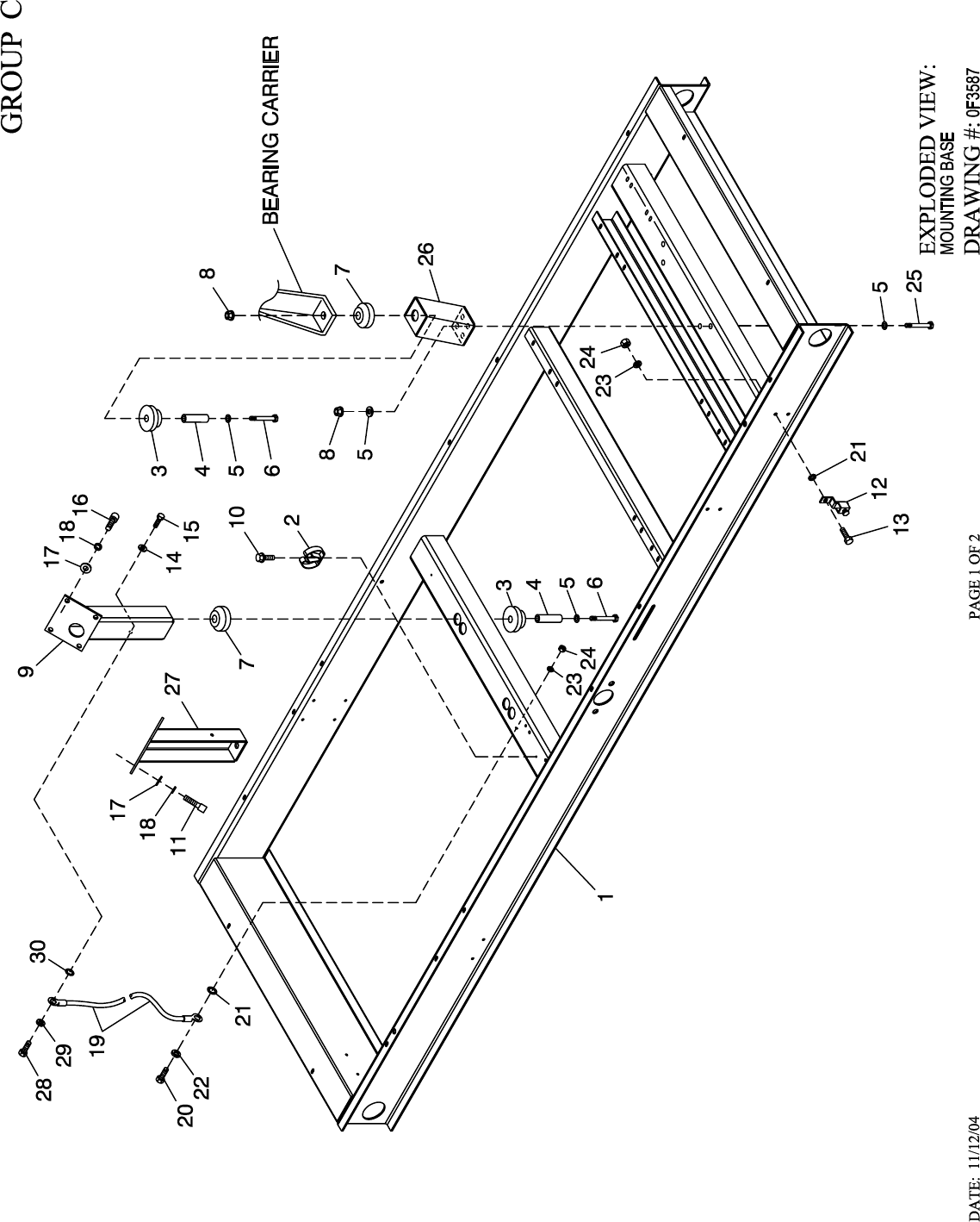
1 0F3384 1 BASE CPL 100-130KW 6.8L GB
2 065852 1 SPRING CLIP HOLDER .37-.62
3 052252 4 DAMPENER VIBRATION
4 052257 4 SPACER .49 X .62 X 1.87 PWDR/ZINC
5 052259 8 WASHER FLAT M12
6 055597 4 SCREW HHC M12-1.75 X 85 G8.8
7 052251A 4 DAMPENER VIBRATION 50 WHITE
8 052860 4 NUT LOCKING M12-1.75
9 0F2895 1 SUPPORT ENG 5.4L LH/RH 6.8L RH
10 045764 1 SCREW HHTT M4-0.7 X 8 BP
11 090502 4 SCREW SHC M10-1.5 X 60 G12.9
12 061383 1 LUG SOLDERLESS 3/0-#4 X 13/32 CU
13 043107 1 SCREW HHC M8-1.25 X 25 G8.8
14 022473 1 WASHER FLAT 1/4-M6 ZINC
15 049813 1 NUT HEX M6 X 1.0 G8 YEL CHR
16 057192 4 SCREW SHC M10-1.5 X 30 G12.9
17 022131 8 WASHER FLAT 3/8-M10 ZINC
18 046526 8 WASHER LOCK M10
19 0536210360 1 WIRE ASSEM #4GA GRD
20 042909 1 SCREW HHC M8-1.25 X 30 G8.8
21 022261 2 WASHER SHAKEPROOF INT 3/8
22 022129 1 WASHER LOCK M8-5/16
23 022145 2 WASHER FLAT 5/16-M8 ZINC
24 045771 2 NUT HEX M8-1.25 G8 YEL CHR
25 053557 4 SCREW HHC M12-1.75 X 40 G8.8
26 0F2591 2 TOWER GB COMPROD C5
27 0F2910 1 SUPPORT ENGINE 6.8L LH SIDE
28 038750 1 SCREW HHC M6-1.0 X 30 G8.8
29 022097 1 WASHER LOCK M6-1/4
30 022447 1 WASHER SHAKEPROOF INT 1/4
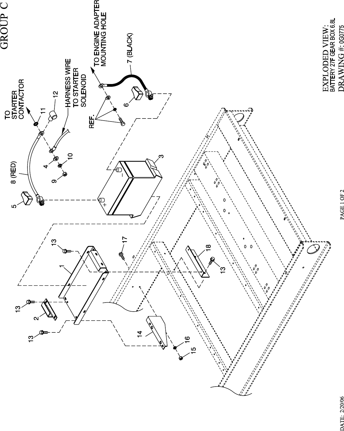
1 0F3408A 1 TRAY BATTERY 27F
2 0F3411A 1 STRAP BATTERY RETAINMENT 27F
3 058665 1 BATTERY 12VDC 90-AH 27F
4 022131 1 WASHER FLAT 3/8-M10 ZINC
5 050331A 1 BATTERY POST COVER RED +
6 050331 1 BATTERY POST COVER BLK -
7 038805Z 1 CABLE BATTERY BACLK #1 X 26.00
8 038804U 1 CABLE BATTERY RED #1 X 28.00
9 045771 1 NUT HEX M8-1.25 G8 YEL CHR
10 022129 1 WASHER LOCK M8-5/16
11 027482 1 WASHER SHAKEPROOF EXT 5/16 STL
12 075763 1 BOOT BATTERY CABLE
13 0C2454 8 SCREW THF M6-1 X 16 N WA Z/JS
14 0F3409 1 SUPPORT BATTERY TRAY
15 022097 2 WASHER LOCK M6-1/4
16 049813 2 NUT HEX M6 X 1.0 G8 YEL CHR
17 042568 2 SCREW HHC M6-1.0 X 20 G8.8
18 0G0783 1 SUPPORT 27F BATTERY
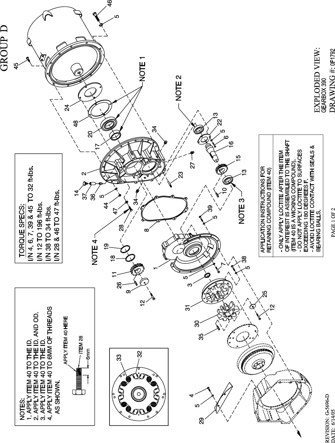
1 0F2123 1 GEAR CASE ENG. MACHINED
2 0F2122 1 GEAR CASE ALT. MACHINED
3 095613 1 SEAL OIL
4 051756 2 SCREW HHC M10-1.5 X 20 G8.8
5 046526 44 WASHER LOCK M10
6 049814 4 SCREW HHC M10-1.5 X 25 G8.8
7 051735 8 SCREW HHC M10-1.5 X 70 G8.8
8 0F2097 1 GASKET 390 GEARBOX
9 072879 1 SPACER .69 X 2.75 X .37 ST/ZNC
10 097557B 1 KEY 10 X 16 X 46
11 097785 1 GEAR OUTPUT 1.65:1
095970 1 GEAR OUT 390-50H 37T
095968 1 GEAR OUT 390-60H 35T
0E6866 1 GEAR OUTPUT 2:1 50HZ 390
12 070263 2 SCREW HHC M16-2.0 X 35 G10.9
13 057019 2 BALL BRG 65 X 120 X 23
14 026847 1 BREATHER
15 097784 1 GEAR INPUT 1.65: 1
095969 1 GEAR INPT 390-50 25T
095967 1 GEAR INPT 390-60 27T
0E6865 1 GEAR INPUT 2:1 50HZ 390
16 095966 1 SHAFT 390 INPUT GEAR
17 095976 1 COLLAR HARDENED
18 095971 1 SEAL OIL
19 096777 1 SNAP RING INT 120MM
20 057019S 1 BEARING #6213 SEALED
22 096379 1 PLATE INTRNL BRG RET
23 048189 2 PIN DOWEL M8 X 24
24 095979 1 PLATE BEARING THRST
25 021159 1 SPACER STRESSPROOF
26 097557A 1 KEY 10 X 16 X 40
27 057163 1 PLUG PIPE 3/8" MAGNETIC
28 0F6518 4 SCREW HHFC M10-1.5 X 25 G10.9
29 0F3201 1 COVER GEARBOX GUARD
30 020443 1 COUPLING INNER DRAWN
31 094666A 1 COUPLING OUTER MACHN
32 099828 8 DAMPER GB CPLR VIBRA
33 099828A 8 DAMPER GB CPLR VIBRA
34 026925 2 PLUG STD PIPE 3/8 STEEL SQ HD
35 097557C 1 KEY 10 X 16 X 50
36 038591 1 NIPPLE PIPE 3/8 NPT X 3-1/2
37 025066 1 COUPLING FULL 3/8-18
38 031578 6 SCREW HHC 3/8-16 X 1-1/2 G8
052625 REF. SCREW SHC M10-1.5 X 35 G12.9 (FORD ENGINES)
39 049814 10 SCREW HHC M10-1.5 X 25 G8.8
40 0A1786 2.5cc RETAINING COMPOUND
41 027175 .200 GAL LUBE GREASE SAE #90 80W90 (NOT SHOWN)
44 045772 10 NUT HEX M10-1.5 G8 YEL CHR
45 052243 10 SCREW HHC M10-1.5 X 60 G8.8
46 057642 2 SCREW HHC M10-1.5 X 40 G10.9
47 0F6487 4 WASHER FLAT M10 SEALING COPPER
48 0F6355 1 GASKET SEAL PLATE 390 GB
49 0F6477 .050 GAL ENHANCER GEAR OIL (NOT SHOWN)
50 0F6557 0.4cc THREADLOCK AND SEALANT
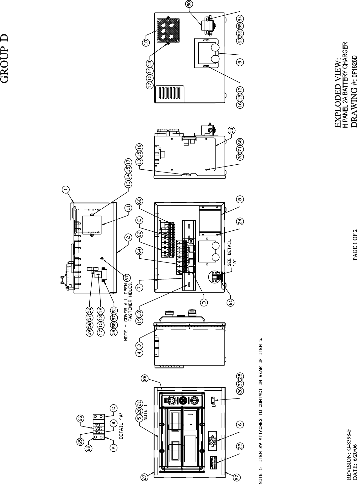

COMPONENTS INCLUDED IN 0F1826E
1 0F1823 1 ENCL H CONTROL PANEL
2 0F1824 1 COVER CONTROL PANEL
3 0F2606 1 HINGE CONTINUOUS H-PNL
4 036261 6 RIVET POP .125 X .275 SS
5 0F5763 1 ASSY PROGRAMMED PM H-100
6 0F1732 1 DECAL FUSES LOCATED INSIDE
7 0E9764 1 RAIL SNAPTRACK PCB HOLDER BULK (12” LG)
8 0F1725C 1 ASSY PCB 2AMP 12V UL BATT CHGR
9 0F1958 1 PLATE HARNESS CLAMP
10 0F2256 1 ASSY PCB PWR AVR W/AMP HEADER
11 0E3161 1 ASSY PCB BOSCH GOV DRIVER
12 029673 1 DIO BRIDGE 25A 600V
13 049226 8 WASHER LOCK M5
14 079224 4 SCREW PPHM M5-0.8 X 30 SS
15 051713 8 WASHER FLAT M5
16 0F5886 3 SCREW HHPM M5-0.8 X 12
17 051716 5 NUT HEX M5-0.8 G8 CLEAR ZINC
18 0C3990 3 SCREW PHTT M4-0.7 X 10 ZYC
19 043280 3 WASHER FLAT M4
20 055014 10 SCREW PPHM M4-0.7 X 8 BLK OX
21 043184 10 WASHER LOCK M4
22 0F2557 1 DECAL WARNING BATT CHRG 12/24V
23 0F5884 1 SCREW PHTT M3.5-0.6 X 10
24 0C2265 4 SCREW PHTT M4-0.7 X 12 ZYC
25 0F4333 1 CONN DUST CAP W/CHAIN DB9
26 0F5883 1 WASHER FLAT M3.5
27 0F6305 2 SEAL COVER 3.18 X 12.7 X 382
28 0F6305A 1 SEAL COVER 3.18 X 12.7 X 283
29 0F6277 1 ASSY HARNESS H-PNL SW (NOT SHOWN)
COMPONENTS INCLUDED IN WIRE HARNESS
A 0F1263 1 ADPTR RH SIDE WICKMAN 178.6191
B 0F1262 4 HOLDER FUSE WICKMANN 178.6150
C 0F1264 1 ADPTR LH SIDE WICKMAN 178.6192
D 0E9049B 1 ASSY PCB G-PANEL RELAY 12VDC
E 055911 1 BLOCK TERM 20A 12 X 6 X 1100V
COMPONENTS NOT INCLUDED IN 0F1826E OR WIRE HARNESS
50 056739 1 RELAY SOLENOID 12VDC PNL MNT
51 - 1 DPE BREAKER SEE DRAWING 0F9280
52 - 1 BOOST RESISTOR SEE DRAWING 0F9280
53 0F2627A 1 COVER CONTROL PANEL SIDE
54 022287 2 SCREW HHC 1/4-20 X 3/4 G5
55 022473 4 WASHER FLAT 1/4-M6 ZINC
56 022097 2 WASHER LOCK M6-1/4
57 043182 3 WASHER LOCK M3
58 051714 3 NUT HEX M3-0.5 G8 YEL CHR
59 052777 3 WASHER FLAT M3
60 0C2323 2 SCREW PHTT #6-32 X 5/8 ZYC
61 0F5459 1 DECAL CPL CONTROL PANEL FUSES
62 0F5461 1 DECAL 5.4/6.8L TB3
63 022127 2 NUT HEX 1/4-20 STEEL
64 0F5460 1 DECAL CPL 5.4/6.8L RELAY BOARD
65 0E7403C 1 FUSE ATO TYPE 15 AMP (BLUE)
66 0E7403B 2 FUSE ATO TYPE 10 AMP (RED)
67 0F6145 A/R SEAL WEATHER .45" DIA
68 091526 4 SCREW PPHM M5-0.8 X 12 ZNC
69 0C2699 2 SCREW PHTT #6-32 X 3/8 ZYC
70 051713 4 WASHER FLAT M5
71 049226 4 WASHER LOCK M5
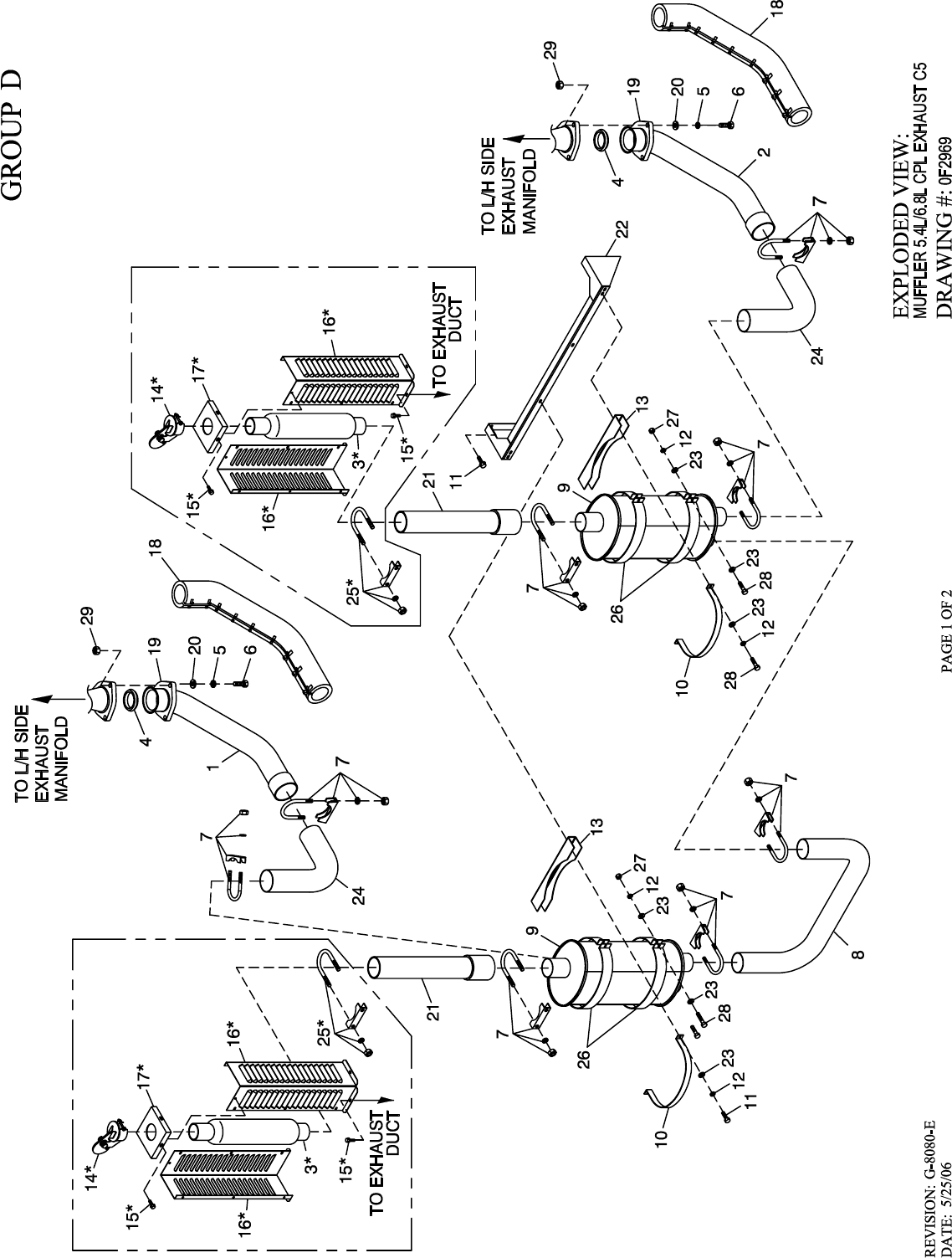
1 0F2807C 1 PIPE EXH MAN R/H 6.8L G/B CPL (6.8L C5)
0F2807E 1 PIPE EXH MAN R/H 5.4L G/B & 2P (5.4L C5)
0F9207 1 PIPE EXH MANIFOLD 4.6L RH
2 0F2807B 1 PIPE EXH MAN L/H 6.8L G/B CPL (6.8L C5)
0F2807D 1 PIPE EXH MAN L/H 5.4L G/B & 2P (5.4L C5)
0F9208 1 PIPE EXH MANIFOLD 4.6L LH
3 0F4505 REF GLASS PACK 23.5" LG 2.5" IN/OUT
4 0A6765 2 RING GASKET 2.5 DIA
50F4710 6WASHER LOCK M10 SS
6 0F7200 6 SCREW HHC M10-1.5 X 50 SS FTH
7 080762 8 BOLT U 3/8-16 X 2.62
8 0F2809 1 PIPE EXHAUST CROSSOVER
9 0F2981A 2 MFLR 7" X 9" X 25" (2) 2.5" IN/2.5" OUT
10 0F2962 2 MUFFLER STRAP
11 0C2454 4 SCREW THF M6-1 X 16 N WA Z/JS
12 022097 8 WASHER LOCK M6-1/4
13 0F2830 2 MUFFLER BRACKET STIFFENER
14 0F4462 REF RAIN CAP ALUM FOR 2-1/2" PIPE
15 0C2454 REF SCREW THF M6-1 X 16 N WA Z/JS
16 0F4367 REF HEAT SHIELD EXHAUST STACK
17 0F4368 REF CAP HEAT SHIELD EXHAUST STACK
18 0F2773C 2 EXHAUST BLANKET 900MM LONG (6.8L C5)
0F2773D 2 EXHAUST BLANKET 850MM LONG (5.4L C5)
19 0D3159 2 FLANGE EXHAUST
20 088775 6 WASHER FLAT 3/8 SS
21 0F2808 2 EXHUAST OUTLET PIPE CPL
22 0F5447 1 BRKT MUFFLER
23 022473 12 WASHER FLAT 1/4-M6 ZINC
24 0F6214 2 PIPE ELBOW EXHAUST MUFFLER
25 080762 REF BOLT U 3/8-16 X 2.62
26 0F6803 4 MUFFLER STRAP UPPER/LOWER
27 049813 4 NUT HEX M6 X 1.0 G8 YEL CHR
28 049721 8 SCREW HHC M6-1.0 X 35 G8.8 BLK
29 088510 6 NUT HEX M10-1.5 SS
* PARTS INCLUDED IN 0F6322 KIT, GLASS PACK SHIP LOOSE.
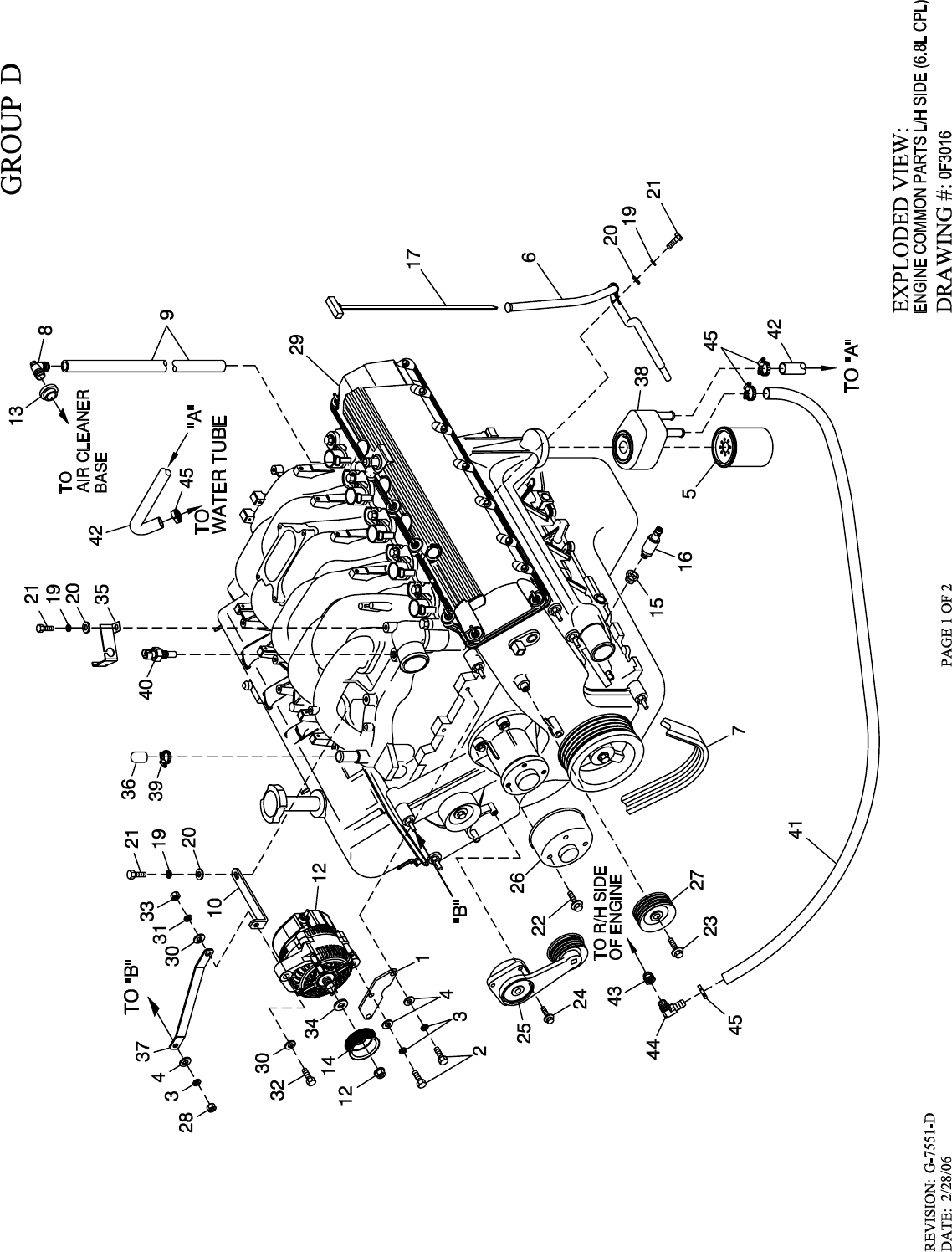
1 0F3017 1 BRACKET,D.C. ALTERNATOR LOWER
2 039253 3 SCREW HHC M8-1.25 X 20 G8.8
3 022129 4 WASHER LOCK M8-5/16
4 022145 4 WASHER FLAT 5/16-M8 ZINC
5 ** 0D5419 REF OIL FILTER, FORD V-10 ENGINE
6 0D7055 1 DIPSTICK TUBE, FORD 6.8L
7 0D3488G 1 BELT SERPENTINE (65.0" LG) (1800 RPM)
0D3488J 1 BELT SERPENTINE (65.3" LG) (2300 RPM)
0D3488 1 BELT SERPENTINE (67.16" LG) (3000 RPM)
0D3488K 1 SERPENTINE BELT (68.3" LG) (3600 RPM)
8 057795A 1 BARBED EL 90 3/4 PLASTIC
9 0A6283 1 HOSE PREFORMED BLOCK HEATER
10 0F3287 1 BRACKET DC ALTERNATOR UPPER
11 0F5990 1 HARN ENG 6.8L H-100 (NOT SHOWN)
12 0E9868A 1 ALTERNATOR DC W/OUT PULLEY
13 057796 1 GROMMET
14 0F3216 1 PULLEY 80 OD DC ALTERNATOR (1800 RPM)
0F3216A 1 PULLEY 102 OD DC ALTERNATOR (2300 RPM)
0F3216C 1 PULLEY 132 OD DC ALTERNATOR (3000 RPM)
0F3216D 1 PULLEY 160 OD DC ALTERNATOR (3600 RPM)
15 055476 1 BUSHING REDUCER 3/8 TO 1/8 GAL
16 0F4612 1 SENDER OIL PRESSURE 1/8" NPT
17 0D6658 1 DIPSTICK 6.8L FORD
18 * 029333A 2 TIE WRAP UL 7.4" X .19" BLK (NOT SHOWN)
19 022097 3 WASHER LOCK M6-1/4
20 022473 3 WASHER FLAT 1/4 ZINC
21 042568 3 SCREW HHC M6-1.0 X 20 G8.8
22 0D8027 4 BOLT WATER PUMP PULLEY
23 0D8025 1 BOLT GROOVED IDLER PULLEY
24 0D8026 3 BOLT BELT TENSIONER
25 0D8030 1 TENSIONER ENG. AUTOMATIC BELT
26 0F2846 1 PULLEY WATER PUMP FORD (1800RPM UNITS)
0D8029 1 PULLEY ENGINE WATER PUMP (2-POLE & GEAR BOX)
27 0D8028 1 PULLEY GROOVED ENGINE IDLER
28 045771 1 NUT HEX M8-1.25 G8 YEL CHR
29 0D3454 1 ENGINE 6.8L FORD (V-10)
30 022131 2 WASHER FLAT 3/8-M10 ZINC
31 046526 1 WASHER LOCK M10
32 064416 1 SCREW HHC M10-1.5 X 45 G8.8 FT
33 045772 1 NUT HEX M10-1.5 G8 YEL CHR
34 0F3217 1 SPACER DC ALTERNATOR PULLEY
35 0F2776A 1 BRACKET SIGNAL CONDITIONER
36 0F6151 1 CAP RUBBER
37 0F4308 1 BRACKET DC ALT STABILIZER
38 0F3158 1 OIL COOLER FORD (150KW 3600RPM)
39 057823 1 CLAMP HOSE #10 .56-1.06
40 0E0502 1 TEMPERATURE SENDER DELPHI
41 0G0866 1 HOSE OIL COOLER PREFORMED 3/4 (150KW 3600RPM)
42 0F4301 1 HOSE OIL COOLER (150KW 3600RPM)
43 0F4355 1 ADAPTOR 1/2" NPT - 3/8" NPT (150KW 3600RPM)
44 0G0153 1 BARBED EL 90 1/2 NPT X 3/4 HOSE (150KW 3600RPM)
45 057823 4 CLAMP HOSE #10 .56-1.06 (150KW 3600RPM)
* NOTE: I/N 18 IS FOR HOLDING SENSOR TO I/N 35.
**I/N 5 PART OF I/N 29.
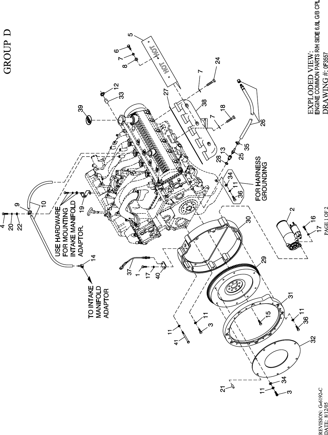
1 039253 1 SCREW HHC M8-1.25 X 20 G8.8
2 0D5418 1 STARTER MOTOR FORD V-10 ENGINE
3 052625 11 SCREW SHC M10-1.5 X 35 G12.9
4 047411 1 SCREW HHC M6-1.0 X 16 G8.8
5 0D5623 2 HEAT SHIELD EXHAUST
6 0D2608 10 SCREW HHC 5/16-18 X 1/2 SSTL
7 070006 30 WASHER LOCK M8 SSTL
8 070008 10 WASHER FLAT M8 SS
9 055934M 1 CLAMP VINYL .75 X .343 Z
10 047290 1 HOSE 3/8 ID SINGLE BRAID (15”)
11 046526 23 WASHER LOCK M10
12 057823 1 CLAMP HOSE #10 .56 - 1.06 (2300 & 3000RPM UNITS ONLY)
13 057765 1 ADAPTER M14-1.50 X 3/8 NPT
14 049340 1 BARBED EL 90 1/4 NPT X 3/8
15 0D5417 REF. SCREW HHC M10-1.0 X 25 G10.9
16 049821 3 SCREW SHC M8-1.25 X 30 G12.9
17 022129 4 WASHER LOCK M8-5/16
18 070010 2 SCREW HHC M8-1.25 X 35 SS F-TH
19 0F2776A 1 BRACKET SIGNAL CONDITIONER
20 022097 1 WASHER LOCK M6-1/4
21 048191 2 DOWEL PIN M10 X 24
22 022473 1 WASHER FLAT 1/4 ZINC
23 * 029333A 1 TIE WRAP UL 7.4" X .19" BLK (NOT SHOWN)
24 0D9913 18 SCREW SHC M8-1.25 X 35 SS
25 055596 1 BARBED STR 3/8 NPT X 3/8
26 069860E 1 HOSE DRAIN ASSY 28"
27 0D4255 2 GASKET EXHAUST MANIFOLD
28 057772 1 WASHER NYLON .565
29 0D6686 1 ASSEMBLY 6.8L G-BOX FLYWHEEL
30 0F3131 1 HOUSING FLYWHEEL 6.8L FORD MCH
31 0D3805 1 COVER FLYWHEEL MACH 6.8L V-10
32 021113 1 PLATE DAMPNER RETNR
33 077996 1 CAP HOSE (2300 & 3000RPM UNITS ONLY)
34 022131 7 WASHER FLAT 3/8-M10 ZINC
35 048031J 1 HOSE CLAMP BAND 5/8"
36 052647 9 SCREW SHC M10-1.5 X 25 G12.9
37 0D2244M 1 ASSY MAGPICKUP(3/8-24 MALE)
38 0D3808 2 EXH MANIFOLD MACH 6.8L V-10
39 0F5114 1 DECAL REFER TO OWNERS MANUAL
40 0F5454 1 PLATE MAG PICK-UP ADAPTOR
41 079121 2 SCREW SHC M10-1.50 X 100 G10.9
* NOTE: I/N 23 IS FOR HOLDING SENSORS TO I/N 19.
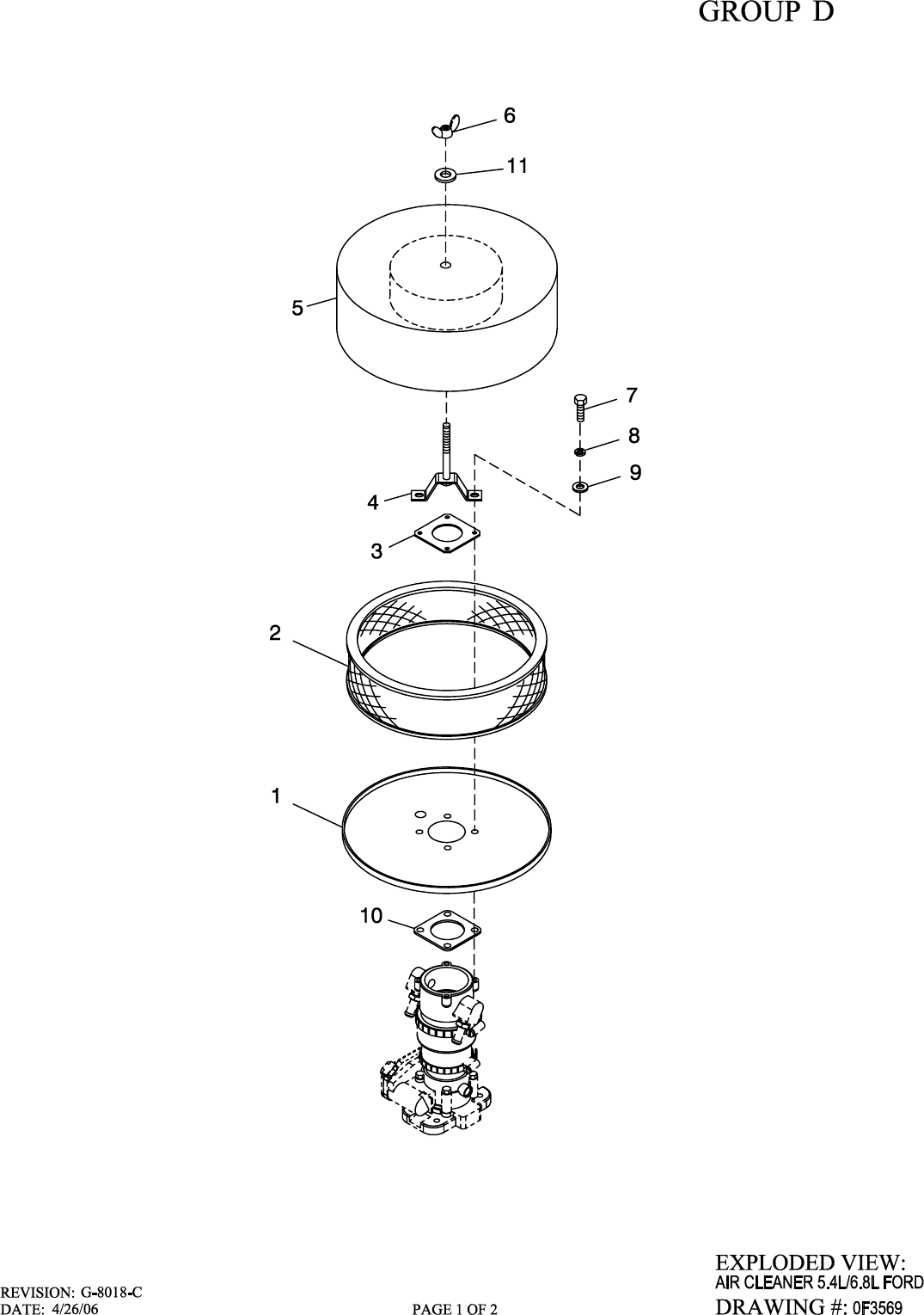

1 0D2513D 1 AIR CLNR BTM PLT W/CPLR 8.1L
2 0F5419 1 ELEMENT AIR FILTER
3 0F4268 1 TOP PLATE VENTURI
4 0F4270A 1 HOLD DOWN AIR CLEANER PLATED
5 0F6977 1 PLATE AIR CLEAN TOP 5.4L/6.8L
6 037561 1 NUT WING 1/4-20 NYLK
7 047411 4 SCREW HHC M6-1.0 X 16 G8.8
8 022097 4 WASHER LOCK M6-1/4
9 049811 4 WASHER FLAT M6
10 0F4269 1 GASKET MIXER BODY
11 022473 1 WASHER FLAT 1/4-M6 ZINC
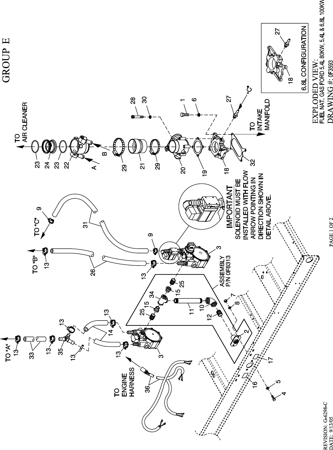
1 049721 4 SCREW HHC M6-1.0 X 35 G8.8 BLK
2 065908 1 SUPPORT NAT GAS SOLENOID
3 0F6261G 1 REGULATOR ASSM 5.4L 80KW NG
0F6261C 1 REGULATOR ASSM 5.4L 100KW NG
0F6261D 1 REGULATOR ASSM 6.8L 100KW NG
4 052617 2 SCREW HHC M12-1.75 X 20 G8.8
5 022304 2 WASHER FLAT 1/2 ZINC
6 022129 4 WASHER LOCK M8-5/16
7 045773 2 NUT HEX M12-1.75 G8 YEL CHR
8 022195 2 WASHER LOCK 1/2
9 040173 2 CLAMP HOSE #5.5 .62-.62 (5.4L)
0C7649 2 CLAMP HOSE .38-.87 (6.8L 100KW)
10 030131 1 ELBOW 90D 1-1/4 NPT
11 031015 1 NIPPLE PIPE 1-1/4 NPT X 3
12 039130 1 NIPPLE CLOSE 1.25 NPT X 1.625
13 057822 9 CLAMP HOSE #8 .53-1.00
14 059057 2 HOSE 3/4 ID SAE-30R2 (42” LG)
15 0A8064 2 BSHG RDCR HEX 1-1/4-3/4
16 0D1509 1 DECAL INLET PRESSURE
17 050279 1 DECAL FUEL INLET NG
18 0F2756A 1 MACHINING, INTAKE ADAPTOR 60MM (5.4L FORD)
0D2696B 1 ADAPTOR THROTTLE BODY (BOSCH) (6.8L FORD GEARBOX)
19 0E4390 1 GASKET GOVERNOR ACTUATOR
20 0E4392 1 ACTUATOR BOSCH 60 GOVERNOR
21 0F0960 1 REDUCER 3.0" TO 2.75" TURBO
22 0F3885 1 MIXER 40/60MM ACTUATOR ASSY
23 0F3694 2 O-RING 2-7/8 X 3-1/16 X 3/32
24 0F3691C 1 VENTURI THROTTLE 38MM (5.4L 80KW)
0F3691D 1 VENTURI THROTTLE 40MM (5.4L FORD 2-POLE 100KW)
0F3691E 1 VENTURI THROTTLE 42MM (6.8L FORD GEARBOX 100KW)
25 026915 2 NIPPLE CLOSE 3/4 X 1.375
26 059057 1 HOSE 3/4 ID SAE-30R2 (42” LG)
27 035461 1 BARBED STR 1/4 NPT X 3/8 (5.4L 80KW & 100KW NG)
081017 1 BARBED STR 1/4 NPT X 1/2 (6.8L 100KW NG)
28 046580 4 SCREW SHC M6-1.0 X 45 G12.9
29 039294 2 CLAMP HOSE #44 2.31-3.25
30 022097 4 WASHER LOCK M6-1/4
31 047290 1 HOSE 3/8 ID SINGLE BRAID (42” LG)
052223 1 HOSE 1/2 ID SAE-30R2 FUELOIL (42” LG) (6.8L 100KW)
32 0D2698 1 GASKET ADAPTER THROT BODY (6.8L FORD ONLY)
33 059057 1 HOSE 3/4 ID SAE-30R2 (42” LG)
34 064346 1 PIPE TEE 1-1/4 NPT
35 0F4408 1 Y CONNECTOR 500 SERIES BARBS
36 0F6279 1 HARNESS FUEL JUMPER DUAL REG
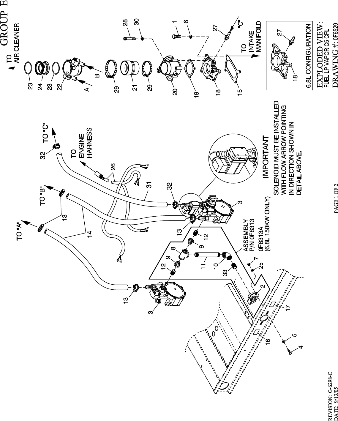
1 033212 4 SCREW HHC 5/16-18 X 1-1/4 G5
2 065908 1 SUPPORT NAT GAS SOLENOID
3 0F6261H 1 REGULATOR ASSM 5.4L 80KW LPV (5.4L 80KW)
0F6261J 1 REGULATOR ASSM 5.4L 100KW LPV (5.4L 100KW)
0F6261K 1 REGULATOR ASSM 6.8L 100KW LPG (6.8L 100KW)
0F6261L 1 REGULATOR ASSM 6.8L 130KW LPV (6.8L 130KW)
0F6261M 1 REGULATOR ASSM 6.8L 150KW LPV (6.8L 150KW)
4 052617 2 SCREW HHC M12-1.75 X 20 G8.8
5 022304 2 WASHER FLAT 1/2 ZINC
6 022129 4 WASHER LOCK M8-5/16
7 045773 2 NUT HEX M12-1.75 G8 YEL CHR
8 064346 1 PIPE TEE 1-1/4 NPT
9 0A8064 2 BSHG RDCR HEX 1-1/4-3/4
10 030131 1 ELBOW 90D 1-1/4 NPT
11 031015 1 NIPPLE PIPE 1-1/4 NPT X 3
088963 1 NIPPLE PIPE 1.25 NPT X 5.5 BL IRN (6.8L 150KW ONLY)
12 026915 2 NIPPLE CLOSE 3/4 X 1.375
13 057823 4 CLAMP HOSE #10 .56-1.06
14 059057 2 HOSE 3/4 ID SAE-30R2 (45” LG)
15 0D2698 1 GASKET ADAPTER THROT BODY
16 0D1509 1 DECAL INLET PRESSURE
17 050280 1 DECAL FUEL INLET LPG (LP VAPOR APPLICATION)
18 0D2696B 1 ADAPTOR THROTTLE BODY (BOSCH) (6.8L)
0F2756A 1 MACHINING INTAKE ADAPTOR 60MM (5.4L)
19 0E4390 1 GASKET GOVERNOR ACTUATOR
20 0E4392 1 ACTUATOR BOSCH 60 GOVERNOR
21 0F0960 1 REDUCER 3.0" TO 2.75" TURBO
22 0F3885 1 MIXER 40/60MM ACTUATOR ASSY
23 0F3694 2 O-RING 2-7/8 X 3-1/16 X 3/32
24 0F3691B 1 VENTURI THROTTLE 36MM (5.4L 80KW)
0F3691D 1 VENTURI THROTTLE 40MM (5.4L 100KW)
0F3691E 1 VENTURI THROTTLE 42MM (6.8L 100KW)
0F3691F 1 VENTURI THROTTLE 44MM (6.8L 130KW)
0F3691J 1 VENTURI THROTTLE 50MM (6.8L 150KW)
25 022195 2 WASHER LOCK 1/2
26 0F6279 1 HARNESS FUEL JUMPER DUAL REG
27 081017 1 BARBED STR 1/4 NPT X 1/2
28 046580 4 SCREW SHC M6-1.0 X 45 G12.9
29 039294 2 CLAMP HOSE #44 2.31-3.25
30 022097 4 WASHER LOCK M6-1/4
31 047290 1 HOSE 3/8 ID SINGLE BRAID (42” LG)
32 040173 2 CLAMP HOSE #5.5 .62-.62
33 039130 1 NIPPLE CLOSE 1.25 NPT X 1.625
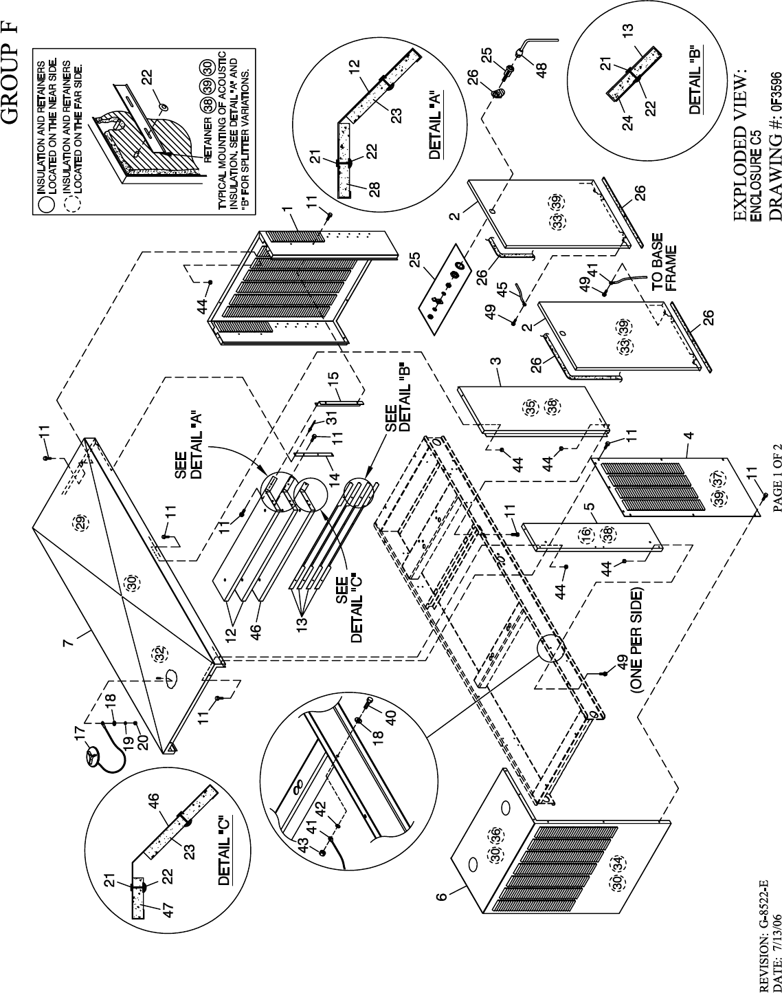
(2) 1 0F5873 1 REAR WRAP C5
(2) 2 0F5868 4 DOOR C5
(2) 3 0F5872 2 CENTER SUPPORT C5
(2) 4 0F5871 2 DISCHARGE DUCT LH & RH SIDE C5
(2) 5 0F5869 2 FRONT CORNERS C5
(2) 6 0F5870 1 DISCHARGE CENTER DUCT C5
(2) 7 0F5867 1 ROOF C5 ALUM
11 0C2454 78 SCREW THF M6-1 X 16 N WA Z/JS
12 0F2766 2 SPLITTER
13 0F3181 4 SPLITTER SHORT
14 0F3185 2 STRINGER SPLITTER C3
15 0F3416 2 SUPPORT SPLITTER C5 130KW
16 0F3949 2 INSULATION CORNER POST
17 0C2634A 1 ASSEMBLY COVER ACCESS
18 022473 5 WASHER FLAT 1/4-M6 ZINC
19 022097 1 WASHER LOCK M6-1/4
20 022127 1 NUT HEX 1/4-20 STEEL
21 0F3072 20 INSULATION RETAINMENT HANGER
22 078115 70 WASHER SELF LOCKING DOME
23 0F3949B 3 INSULATION SPLITTER
24 0F3949A 4 INSULATION SHORT LOUVER
25 0F5048D 4 VISE-ACTION LATCH SLOTTED CIR
26 0E5968 1 GASKET EXTRUDED TRIM (566” LG)
27 0F5049 4 TAB PULL
28 0F3949L 2 INSULATION SPLITTER SML
29 0F3949E 1 INSULATION ROOF TOP REAR
30 0F3890A 8 RETAINER INSULATION (740)
31 087233 2 RIVET POP .1875 X .450 SS
32 0F3949C 1 INSULATION ROOF TOP
33 0F3949D 4 INSULATION DOOR
34 0F3949G 1 INSULATION DISCHARGE DUCT
35 0F3949J 2 INSULATION CENTER SUPPORT
36 0F3949K 1 INSULATION DISCHARGE DUCT TOP
37 0F3949F 2 INSULATION INNER DUCT SIDE
38 0F3890B 4 RETAINER INSULATION (820)
39 0F3890 14 RETAINER INSULATION (450)
40 042568 4 SCREW HHC M6-1.0 X 20 G8.8
41 0912970088 2 ASSY WIRE 14 AWG 20.9" GRN/YEL
42 022447 4 WASHER SHAKEPROOF INT 1/4
43 049813 4 NUT HEX M6 X 1.0 G8 YEL CHR
(1)44 077992 28 NUT HEX LOCK M6-1.0 SS NY INS
45 0912970094 2 ASSY WIRE 14 AWG 34.8" GRN/YEL
46 0F2766A 1 SPLITTER C5
47 0F3949M 1 INSULATION SPLITTER SHRT MPS
48 0F8869D 1 KEY VISE-ACTION LATCH SLOT CIR
49 0E3257 6 SCREW TH-FRM M6 W/CAP SHKPRF W
(1) ALUMINUM ENCLOSURE NOTE: ALL ENCLOSURE PANELS THAT FASTEN TO
THE BASE FRAME MUST BE SECURED USING ITEM 11 & 49 THREAD FORMING
FASTENER AND ITEM 44 LOCK NUT. LOCK NUT IS TO BE INSTALLED AFTER THREAD
FORMING FASTENER HAS PENETRATED THROUGH EXTRUSIONS IN ENCLOSURE PANELS.
ALL ROOF PANELS ARE TO BE SECURED IN THE SAME MANNER.
(2) I/N’S 1 THRU 7, REFER TO CHART BELOW FOR ENCLOSURE COLOR & MATERIAL TYPE.
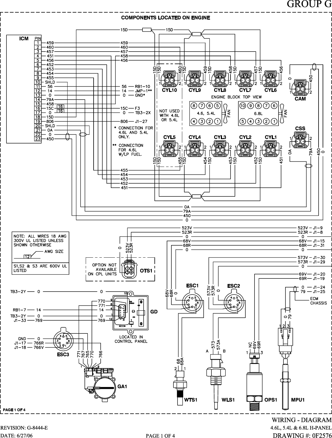
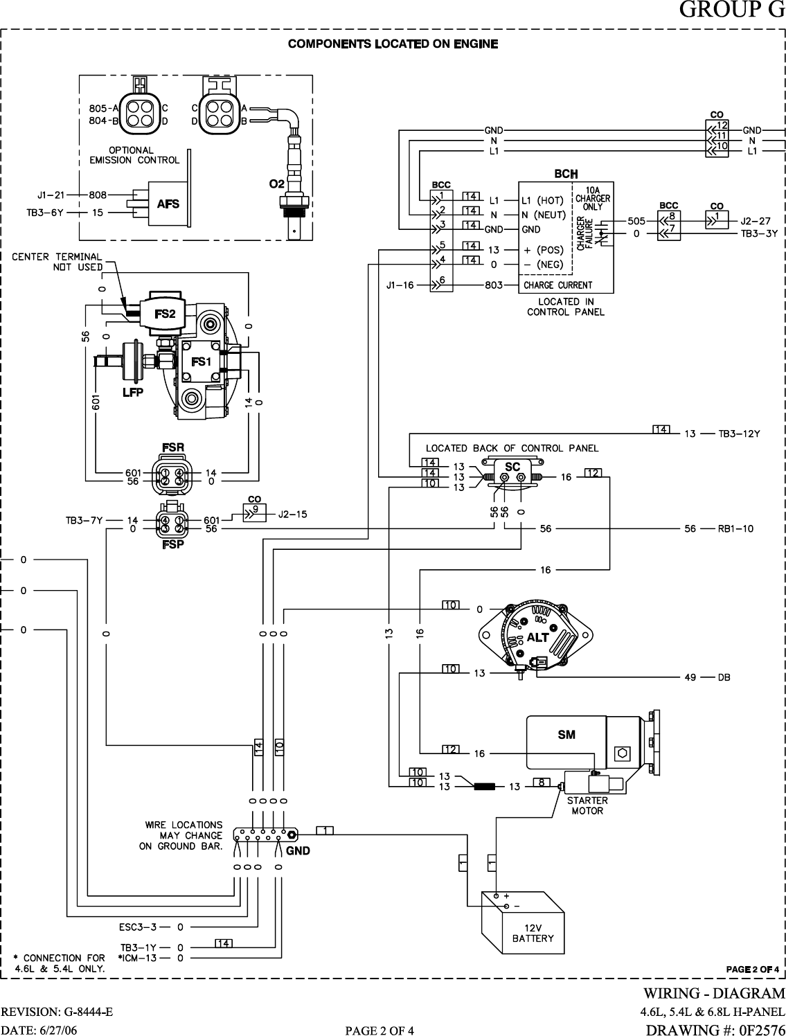
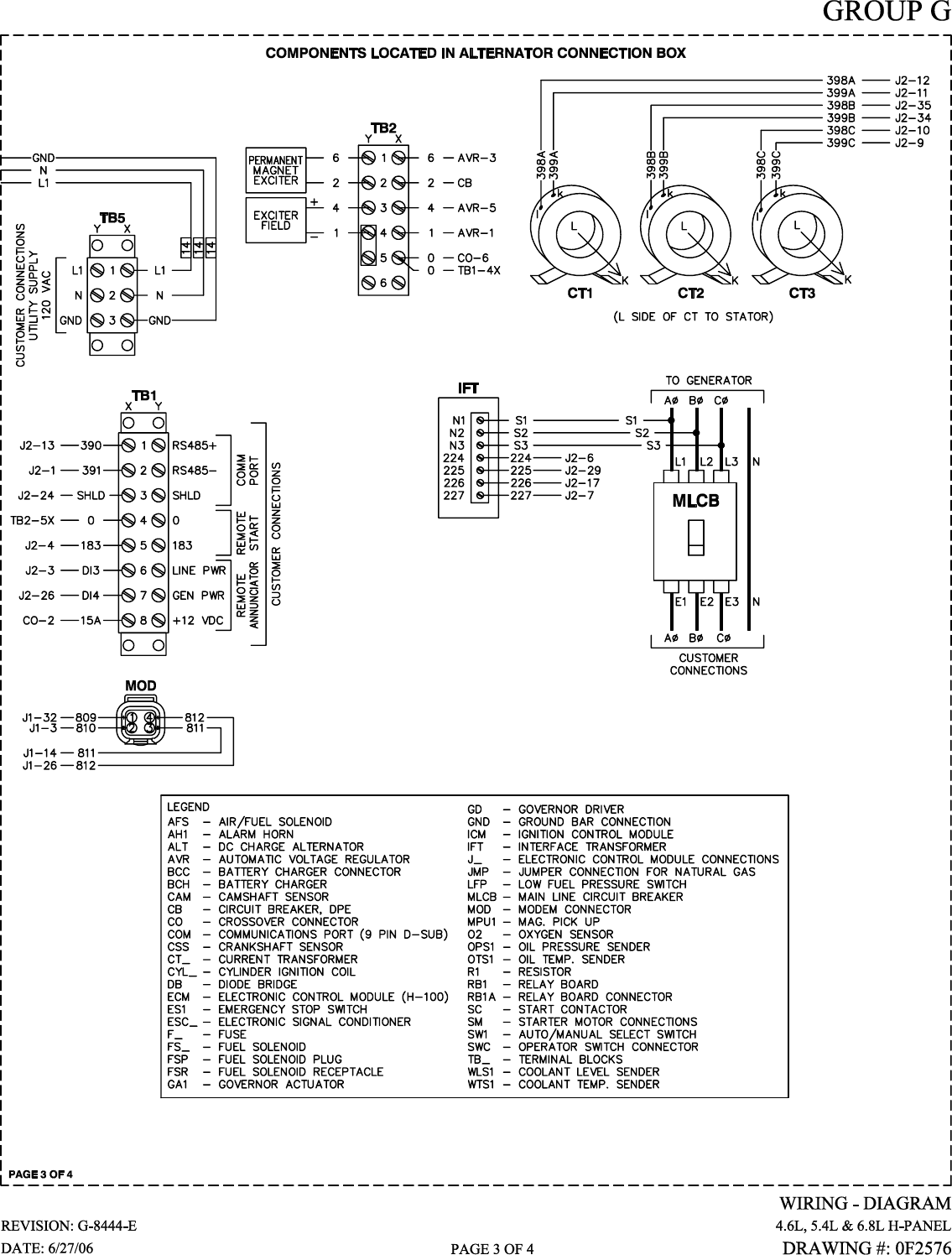
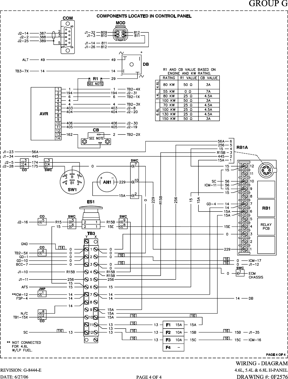
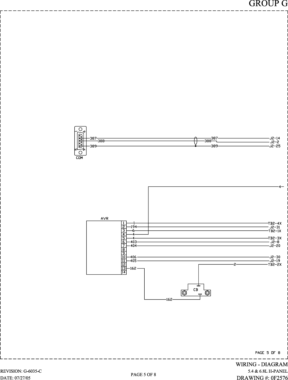
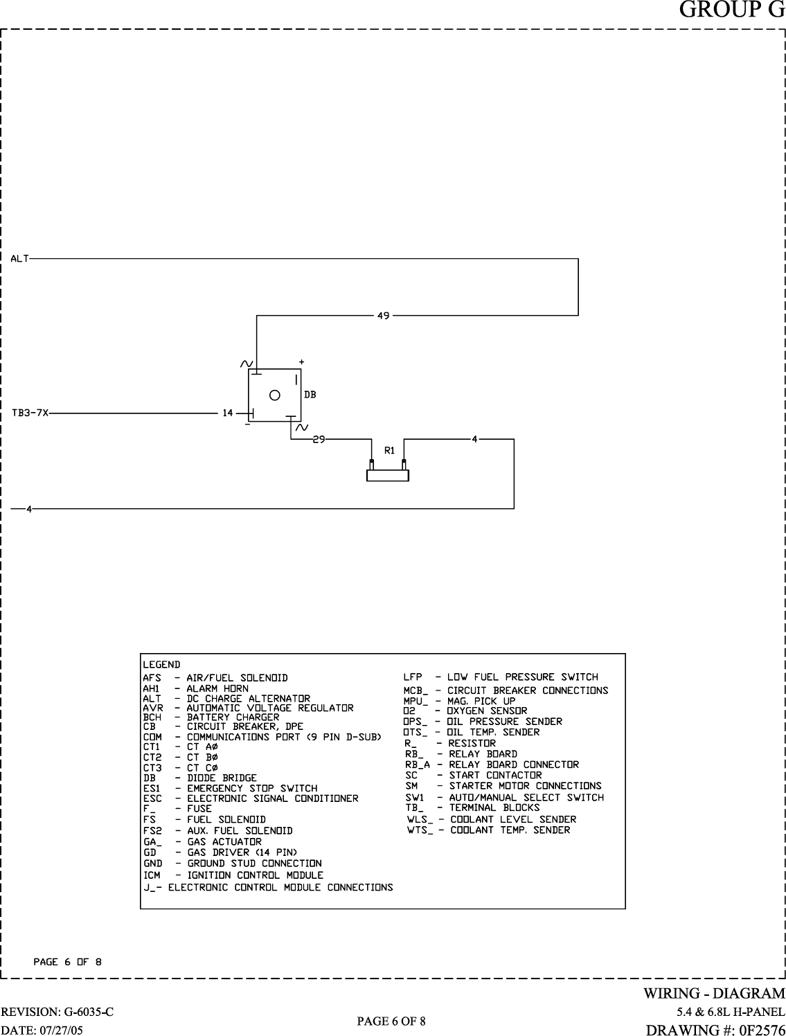
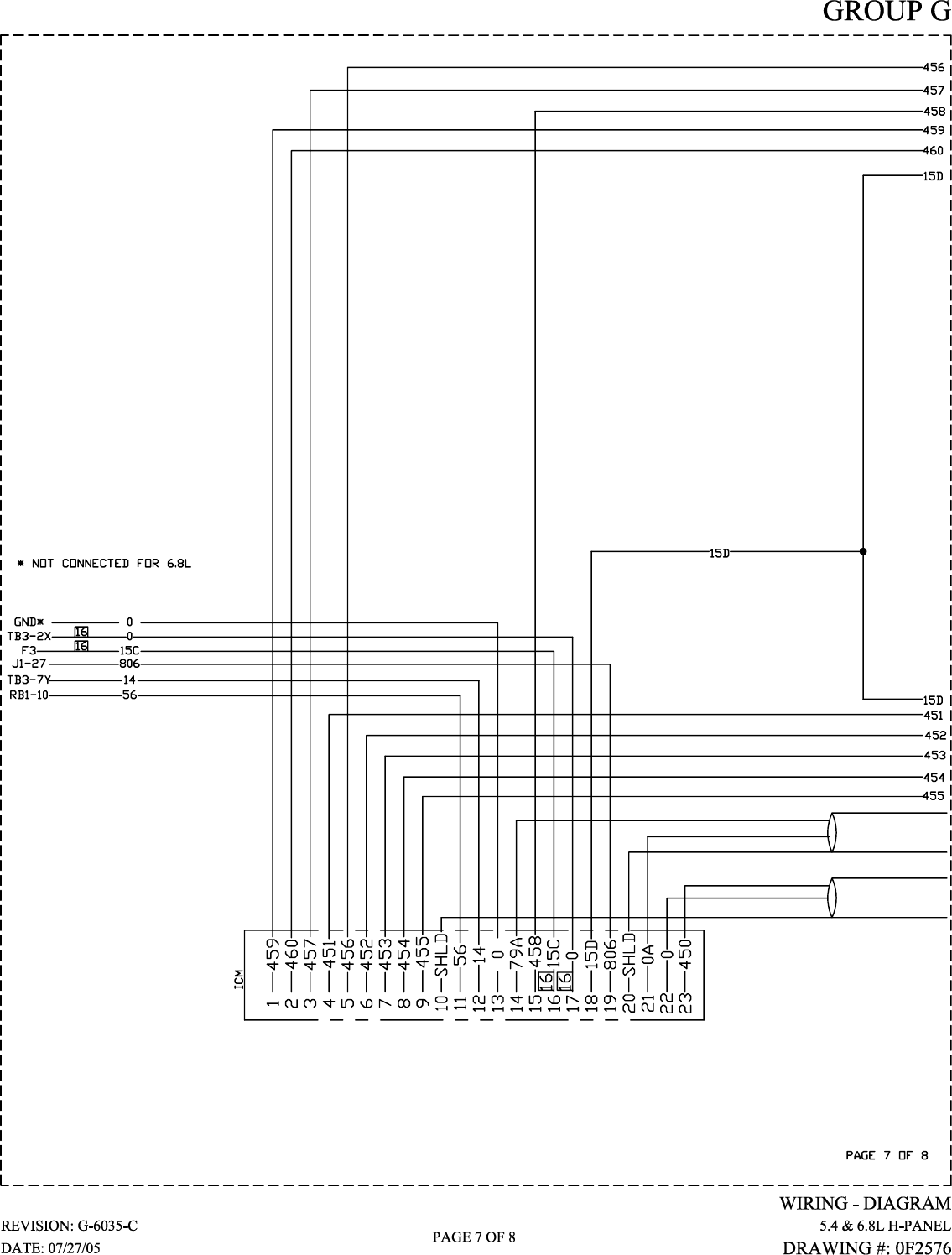
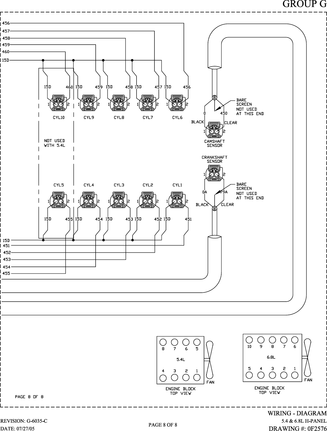
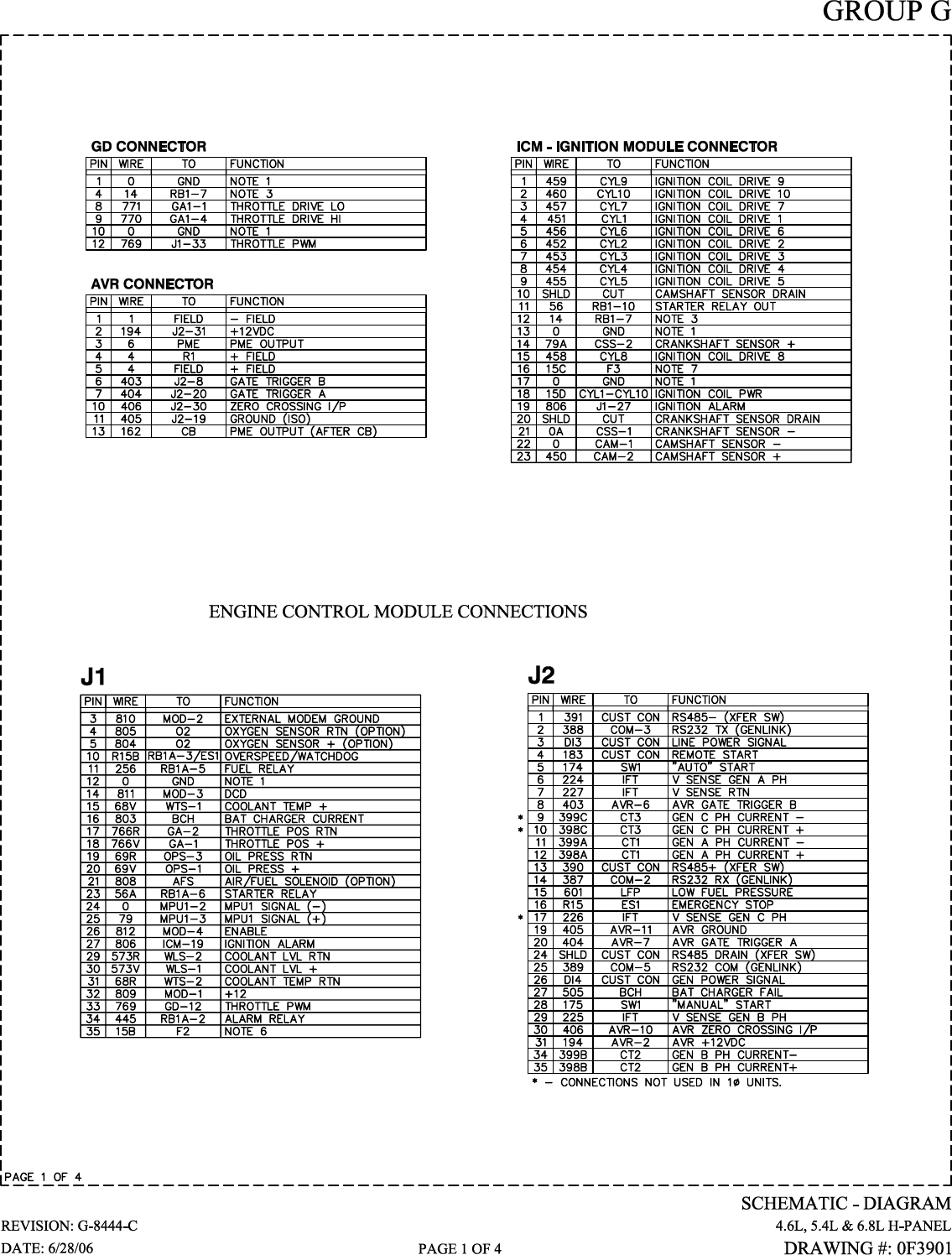
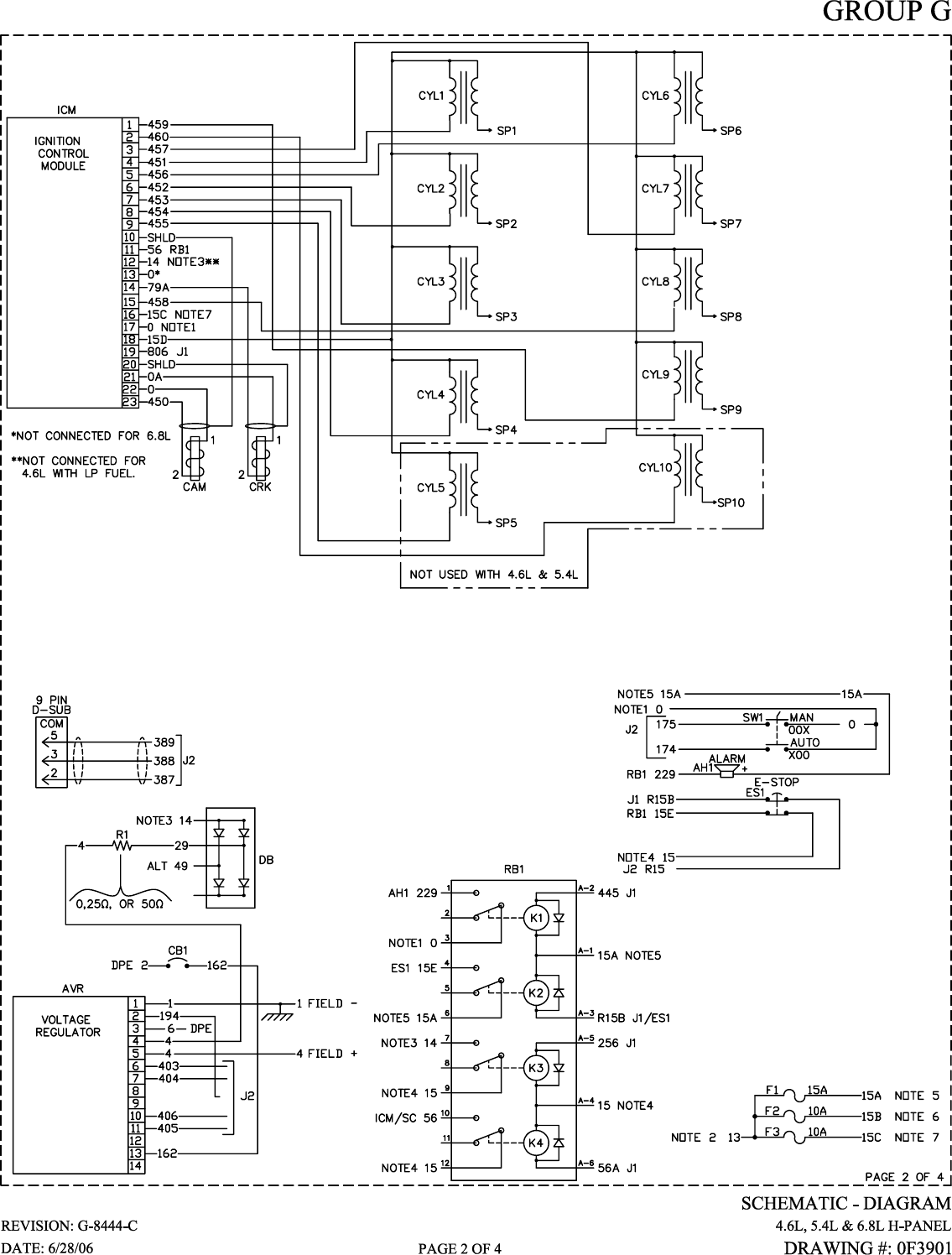
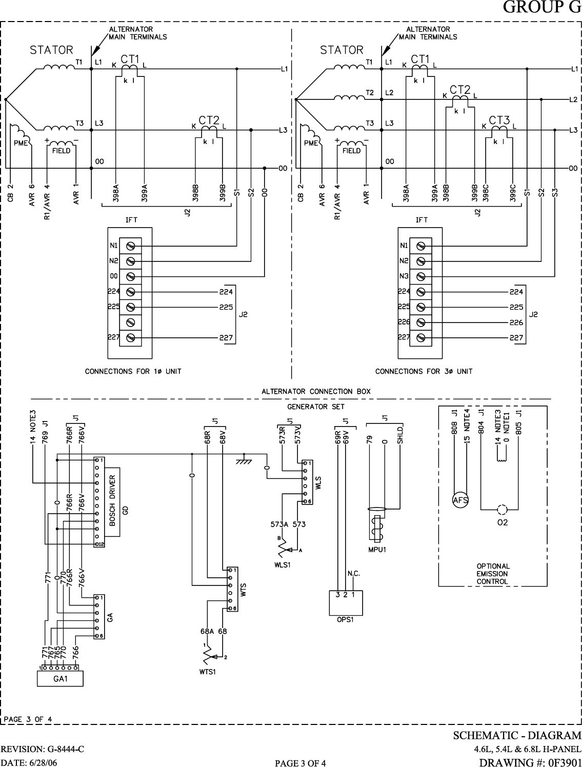
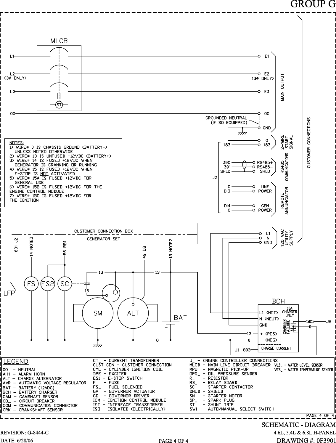
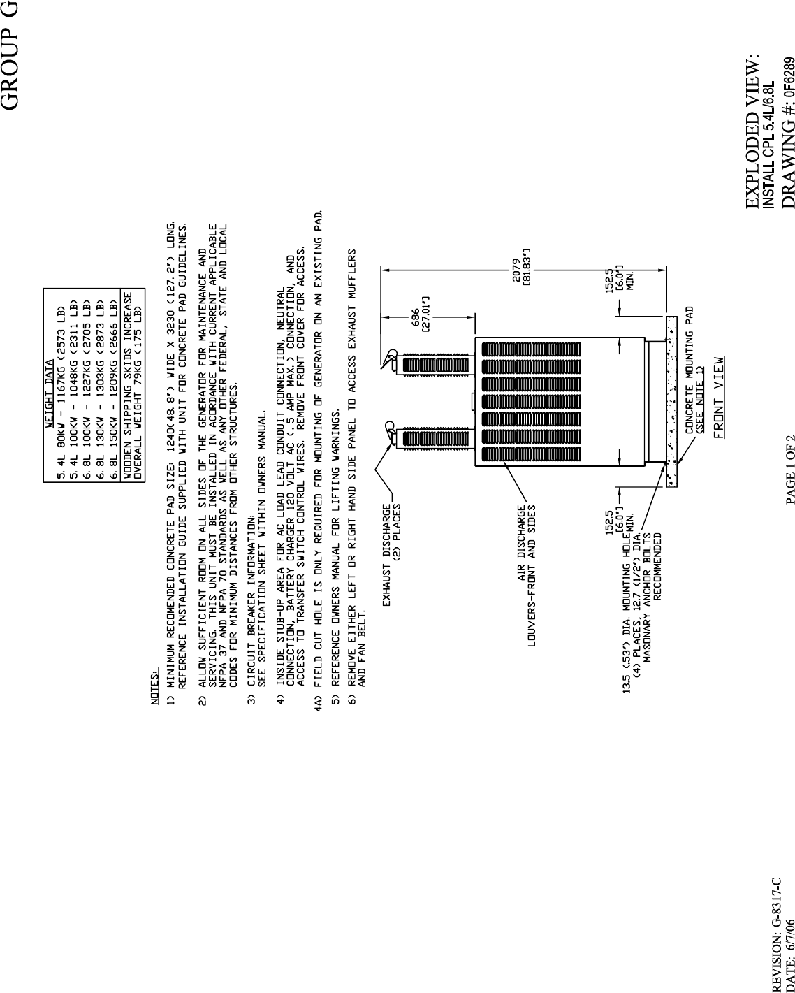
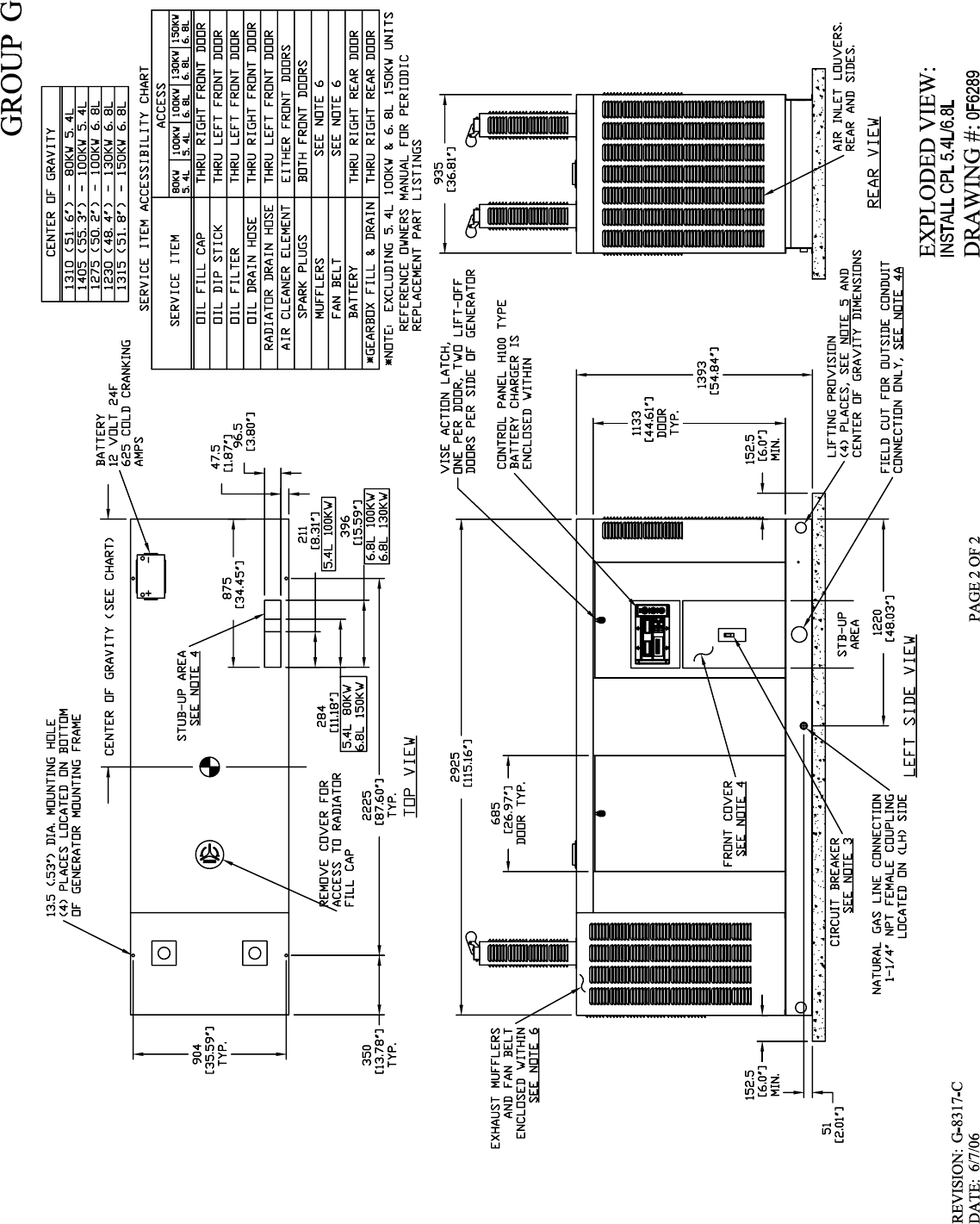
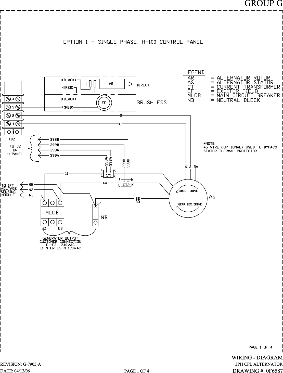
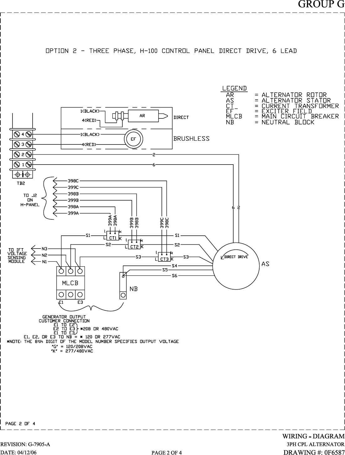
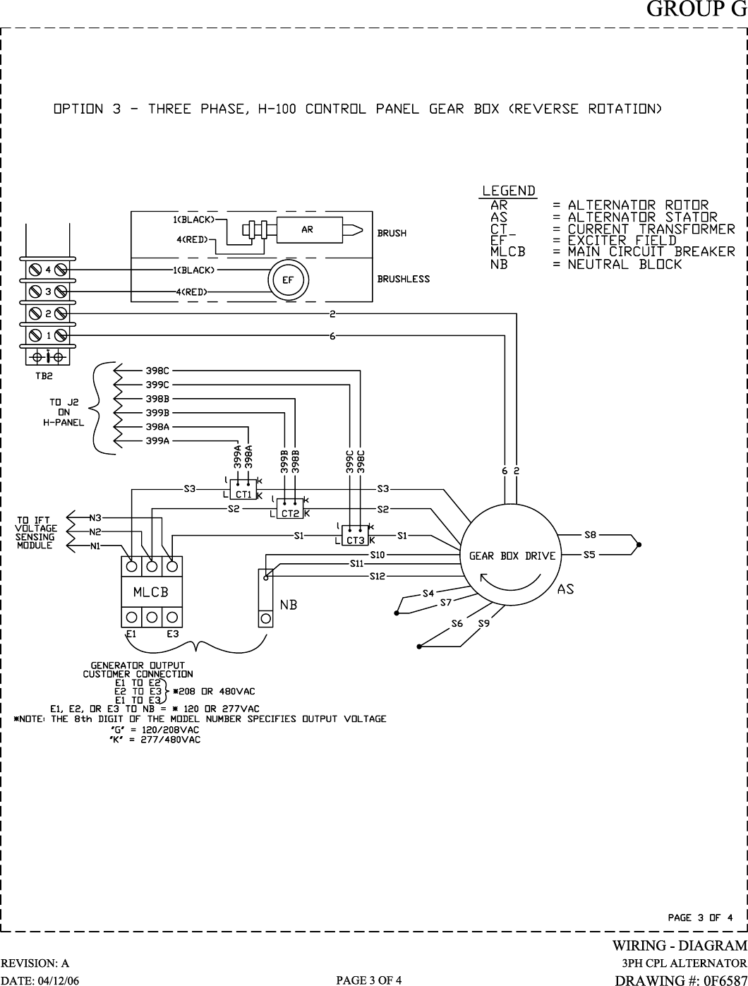
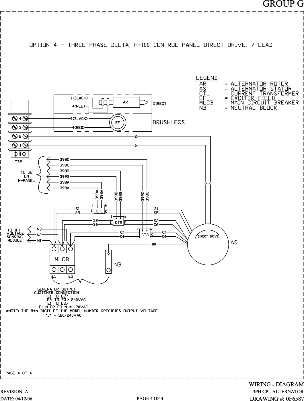
Standby Generator Sets
Warranty
Printed in U.S.A.
GENERAC POWER SYSTEMS STANDARD LIMITED WARRANTY FOR
COMMERCIAL PRODUCT 50kW AND ABOVE
For a period of two (2) years from the date of sale, or start-up by Authorized/Certified Generac Power Systems Dealer, or branch thereof, Generac
Power Systems, Inc. will, at its option, repair or replace any part(s) which, upon examination, inspection, and testing by Generac Power Systems or
an Authorized/Certified Generac Power Systems Dealer, or branch thereof, is found to be defective under normal use and service, in accordance with
the warranty schedule set forth below. Any equipment that the purchaser/owner claims to be defective must be examined by the nearest Authorized/
Certified Generac Power Systems Dealer, or branch thereof. This warranty applies only to Generac Power Systems Generators used in "Standby"
applications, as Generac Power Systems, Inc. has defined Standby, provided said generator has been properly installed and inspected on-site by
appropriate personnel. Scheduled maintenance, as outlined by the generator owner's manual, is highly recommended. This should be performed by
an Authorized/ Certified Generac Power Systems Dealer, or branch thereof. This will verify service has been performed on the unit throughout the war-
ranty period.
WARRANTY SCHEDULE
YEAR ONE — Limited comprehensive coverage on mileage, labor, and parts listed.
• - ALL COMPONENTS
YEAR TWO — Limited comprehensive coverage on parts listed.
• - ALL COMPONENTS
*Start-up and/or On-line Registration, or Registration Card, along with Proof of Purchase, must be performed and/or sent in.
Guidelines:
• Any and all warranty repairs and/or concerns, must be performed and/or addressed by an Authorized/Certified Generac Power Systems Dealer, or
branch thereof.
• A Generac Power Systems, Inc. Transfer Switch is highly recommended to be used in conjunction with the genset. If a Non - Generac Power
Systems, Inc. Transfer Switch is substituted for use and directly causes damage to the genset, no warranty coverage shall apply.
• All warranty expense allowances are subject to the conditions defined in Generac Power Systems Warranty, Policies, and Procedures Flat Rate
Manual.
• Units that have been resold are not covered under the Generac Power Systems Warranty, as this Warranty is not transferable.
• Unit enclosure is only covered against rust or corrosion the first year of the warranty provision.
• Use of Non-Generac replacement part(s) will void the warranty in its entirety.
• Engine coolant heaters (block-heaters), heater controls and circulating pumps are only covered during the first year of the warranty provision (If
applicable).
THIS WARRANTY SHALL NOT APPLY TO THE FOLLOWING:
1. Any unit built/manufactured prior to March 1, 2005.
2. Costs of normal maintenance (i.e. tune-ups, associated part(s), adjustments, loose/leaking clamps, installation and start-up).
3. Any failure caused by contaminated fuels, oils, coolants/antifreeze or lack of proper fuels, oils or coolants/antifreeze.
4. Units sold, rated or used for "Prime Power", "Trailer Mounted" or "Rental Unit" applications as Generac Power Systems have defined Prime Power,
Trailer Mounted or Rental Unit. Contact a Generac Power Systems Distributor for Prime Power, Trailer Mounted or Rental Unit definition and
warranty.
5. Units used for prime power in place of existing utility power where utility is present or in place of utility power where utility power service does not
normally exist.
6. Failures caused by any external cause or act of God such as, but not limited to, collision, fire, theft, freezing, vandalism, riot or wars, lightning,
earthquake, windstorm, hail, volcanic eruption, water or flood, tornado, hurricane, terrorist acts or nuclear holocaust.
7. Products that are modified or altered in a manner not authorized by Generac Power Systems in writing.
8. Failures due, but not limited to, normal wear and tear, accident, misuse, abuse, negligence, or improper installation or sizing.
9. Any incidental, consequential or indirect damages caused by defects in materials or workmanship, or any delay in repair or replacement of the
defective part(s).
10. Failure due to misapplication, misrepresentation, or bi-fuel conversion.
11. Telephone, facsimile, cell phone, satellite, internet, or any other communication expenses.
12. Rental equipment used while warranty repairs are being performed (i.e. rental generators, cranes, etc.).
13. Overtime, holiday, or emergency labor.
14. Planes, ferries, railroad, busses, helicopters, snowmobiles, snow-cats, off-road vehicle or any other mode of transportation deemed abnormal.
15. Any and all expenses incurred investigating performance complaints unless defective Generac materials and/or workmanship were the direct
cause of the problem.
16. Starting batteries, fuses, light bulbs, engine fluids, and overnight freight cost for replacement part(s).
THIS WARRANTY IS IN PLACE OF ALL OTHER WARRANTIES, EXPRESSED OR IMPLIED, SPECIFICALLY, GENERAC POWER SYSTEMS
MAKES NO OTHER WARRANTIES AS TO THE MERCHANTABILITY OR FITNESS FOR A PARTICULAR PURPOSE. Some states do not allow
limitations on how long an implied warranty lasts, so the above limitation may not apply to purchaser/owner.
GENERAC POWER SYSTEMS ONLY LIABILITY SHALL BE THE REPAIR OR REPLACEMENT OF PART(S) AS STATED ABOVE. IN NO EVENT
SHALL GENERAC POWER SYSTEMS BE LIABLE FOR ANY INCIDENTAL, OR CONSEQUENTIAL DAMAGES, EVEN IF SUCH DAMAGES ARE A
DIRECT RESULT OF GENERAC POWER SYSTEMS, INC. NEGLIGENCE.
Some states do not allow the exclusion or limitation of incidental or consequential damages, so the above limitations may not apply to purchaser/
owner. Purchaser/owner agrees to make no claims against Generac Power Systems, Inc. based on negligence. This warranty gives purchaser/owner
specific legal rights. Purchaser/owner also may have other rights that vary from state to state
Generac Power Systems, Inc. • P.O. Box 8 • Waukesha, WI 53187
Ph: (262) 544-4811 • Fax: (262) 544-4851
Bulletin 0171370SVE / Printed in U.S.A. 7.05
