Generac 006000 0 User Manual GENERATOR Manuals And Guides 1403089L
User Manual: Generac 006000-0 006000-0 GENERAC GENERATOR - Manuals and Guides View the owners manual for your GENERAC GENERATOR #0060000. Home:Tool Parts:Generac Parts:Generac GENERATOR Manual
Open the PDF directly: View PDF ![]() .
.
Page Count: 40
MODEL:006000-0
GENERAC
i I
SGenerator
introduction.............................................................1
ReadthisiVlanualThoroughly.................................1
Safety Rules ...........................................................1
StandardsIndex.............................................................3
Generalinformation................................................4
1.1 Unpacking......................................................................4
1.1.1 Accessory Box..................................................4
1.2 Assembly.......................................................................4
1.2.1 Assemblingthe Accessory Kit............................4
Operation................................................................5
2.1 Knowthe Generator.......................................................5
2.2 ConnectionPlugs...........................................................6
2.2.1 120 VAC,20 Amp, DuplexReceptacle...............6
2.2.2 120/240 VAC,20 Amp, Receptacle....................6
2.3 Howto Usethe Generator..............................................6
2.3.1 Groundingthe Generator....................................6
2.3.2 SystemGround..................................................7
2.3.3 ConnectingElectricalLoads...............................7
2.4 Don'tOverloadthe Generator..........................................7
2.5 WattageReferenceGuide...............................................8
2.6 BeforeStartingthe Generator.........................................8
2.6.1 Adding EngineOil..............................................8
2.6.2 ConnectingLP FuelTank....................................8
2.7 Starting Pull Start Engines..............................................9
2.8 Stoppingthe Engine.....................................................10
2.9 Low Oil Level ShutdownSystem..................................10
2.9.1 SensingLow Oil Level......................................10
Maintenance.........................................................10
3.1 MaintenanceSchedule................................................. 10
3.2 ProductSpecifications..................................................10
3.2.1 GeneratorSpecifications..................................10
3.2.2 EngineSpecifications....................................... 10
3.2.3 EmissionsInformation..................................... 10
3.3 GeneralRecommendations...........................................11
3.3.1 GeneratorMaintenance....................................11
3.3.2 ToCleanthe Generator..................................... 11
3.3.3 EngineMaintenance......................................... 11
3.3.4 CheckingOil Level........................................... 11
3.3.5 Changingthe Oil..............................................11
3.3.6 Replacingthe SparkPlug.................................11
3.4 ServiceAir Filter...........................................................12
3.5 ValveClearance............................................................12
3.6 General........................................................................12
3.7 Long TermStorage....................................................... 13
3.8 OtherStorageTips....................................................... 13
Troubleshooting....................................................14
4.1 TroubleshootingGuide..................................................14
Notes....................................................................15
Warranty...............................................................16
iNTRODUCTiON
Thankyou for purchasingthis model by GeneracPowerSystems,
Inc. This model is a compact, high performance, air-cooled,
engine driven generator designed to supply electrical power to
operate electrical loads where no utility power is available or in
place of utility dueto a power outage.
READTHiSMANUALTHOROUGHLY
If any portion of this manual is not understood, contact the
nearest Authorized Dealer for starting, operating and servicing
procedures.
The operator is responsible for proper and safe use of the
equipment. We strongly recommend that the operator read this
manualandthoroughlyunderstandall instructions beforeusingthe
equipment.We also stronglyrecommendinstructingother usersto
properlystart andoperatethe unit.This preparesthem if they need
to operatethe equipmentin an emergency.
The generatorcan operate safely,efficiently and reliably only if it
is properly located, operatedand maintained.Before operatingor
servicing the generator:
•Becomefamiliar with and strictly adhereto all local, state and
nationalcodes and regulations.
•Study all safety warnings in this manual and on the product
carefully.
•Becomefamiliar with this manual andthe unit beforeuse.
The manufacturercannot anticipateevery possible circumstance
that might involvea hazard.The warnings in this manual,and on
tags and decals affixedto the unit are, therefore,not all inclusive.
If using a procedure,work method or operatingtechniquethat the
manufacturerdoes not specifically recommend,ensure that it is
safe for others. Also make sure the procedure,work method or
operatingtechnique utilizeddoes not renderthe generatorunsafe.
THE INFORMATIONCONTAINEDHEREIN WAS BASED ON
MACHINESIN PRODUCTIONAT THE TIME OF PUBLICATION.
GENERACRESERVESTHERIGHTTO MODIFYTHIS MANUALAT
ANYTIME.
Save these instructionsfor future reference, if you loan this
device to someone,ALWAYS loan these instructionsto the
individualas well.
SAFETYRULES
Throughoutthis publication,and on tags and decals affixedto the
generator,DANGER,WARNING,CAUTIONand NOTEblocks are
used to alert personnelto special instructions about a particular
operation that may be hazardous if performed incorrectly or
carelessly. Observe them carefully. Their definitions are as
follows:
iNDICATESAHAZARDOUSSiTUATiONORACTIONWHICH,IF
NOTAVOIDED,WILLRESULTIN DEATHORSERIOUSINJURY.
Indicates a hazardoussituationor action which,if not
avoided, couldresultin deathor seriousinjury.
,ACAUTION!
Indicates ahazardoussituationor action which,if not
avoided, couldresultin minoror moderateinjury.
NOTE:
Notescontainadditionalinformationimportantto aprocedure
and will be foundwithin the regular textbody of thismanual.
These safety warnings cannot eliminate the hazards that they
indicate. Common sense and strict compliance with the special
instructions while performing the action or service areessentialto
preventingaccidents.
Four commonly used safety symbols accompany the DANGER,
WARNINGand CAUTIONblocks. The type of information each
indicates is as follows:
,_This symbol points out important safety
information that, if not followed, could
endanger personal safety and/or property of
others.
This symbol points out potential explosion
hazard.
i/_This symbol points out potential fire hazard.
/i_This symbol points out potential electrical
shock hazard.
GENERAL HAZARDS
•NEVERoperate in an enclosed area, in a vehicle, or indoors
EVENIFdoors and windows areopen.
•For safety reasons, the manufacturer recommends that the
maintenanceof this equipmentis carried out by an Authorized
Dealer.Inspectthe generatorregularly,and contactthe nearest
AuthorizedDealerfor parts needingrepairor replacement.
•Operategeneratoronly on levelsurfacesandwhereit will not be
exposedto excessivemoisture,dirt, dust or corrosive vapors.
•Keep hands, feet, clothing, etc., away from drive belts, fans,
and other moving parts. Neverremoveany fan guardor shield
while the unit is operating.
•Certain parts of the generator get extremely hot during
operation. Keep clear of the generator until it has cooled to
avoid severeburns.
•Do NOToperategeneratorinthe rain.
•Do not alter the construction of the generator or change
controls which might createan unsafeoperatingcondition.
•Never start or stop the unit with electrical loads connected
to receptaclesAND with connected devices turned ON. Start
the engine and let it stabilize before connecting electrical
loads. Disconnect all electrical loads beforeshutting down the
generator.
•Do not insert objectsthrough unit's cooling slots.
•When working on this equipment, remain alert at all times.
Never work on the equipment when physically or mentally
fatigued.
• Neveruse the generatoror any of its parts as a step. Stepping
on the unit can stress and break parts, and may result in
dangerous operating conditions from leaking exhaust gases,
fuel leakage,oil leakage,etc.
EXHAUST &LOCATIONHAZARDS
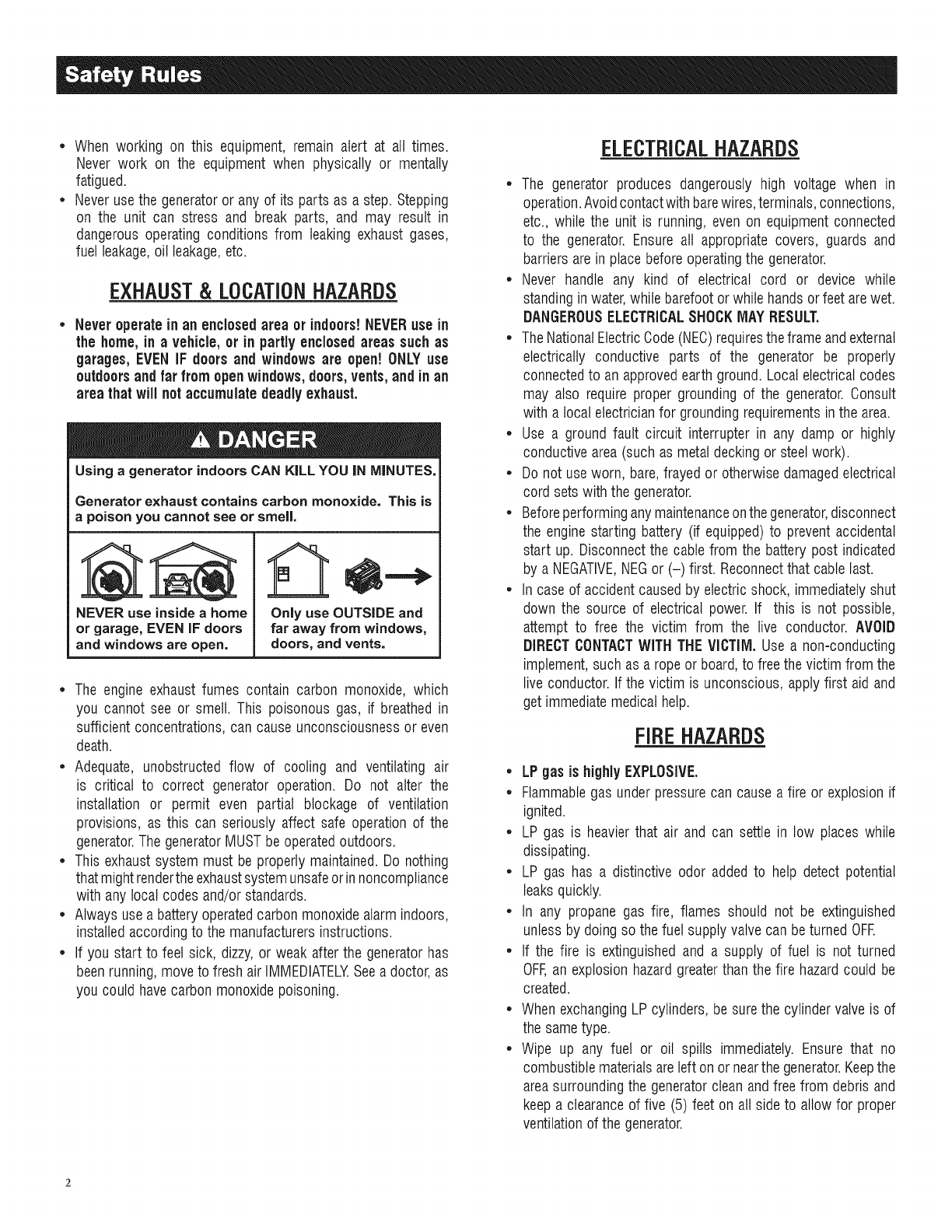
•Never operate in an enclosed area or indoors!NEVERuse in
the home,in avehicle, or in partly enclosed areas suchas
garages,EVEN IF doorsand windowsare open! ONLYuse
outdoors and far from open windows, doors,vents,andinan
area that will notaccumulatedeadlyexhaust.
Using agenerator indoors CAN KILL YOU IN MINUTES.
Generator exhaust contains carbon monoxide. This is
a poison you cannot see or smell,
NEVER use insideahome
or garage, EVEN iF doors
and windows are open,
Only use OUTSIDE and
far away from windows,
doors, and vents.
• The engine exhaust fumes contain carbon monoxide, which
you cannot see or smell. This poisonous gas, if breathed in
sufficient concentrations,can causeunconsciousnessor even
death.
• Adequate, unobstructed flow of cooling and ventilating air
is critical to correct generator operation. Do not alter the
installation or permit even partial blockage of ventilation
provisions, as this can seriously affect safe operation of the
generator.The generatorMUST beoperatedoutdoors.
• This exhaust system must be properly maintained.Do nothing
that mightrenderthe exhaustsystemunsafeorinnoncompliance
with any local codes and/or standards.
• Always use a battery operatedcarbon monoxidealarm indoors,
installedaccordingto the manufacturersinstructions.
• If you start to feet sick, dizzy, or weak after the generator has
beenrunning,moveto fresh air IMMEDIATELYSeea doctor,as
you could have carbon monoxidepoisoning.
ELECTRICALHAZARDS
• The generator produces dangerously high voltage when in
operation.Avoidcontactwith barewires,terminals,connections,
etc., while the unit is running, even on equipmentconnected
to the generator. Ensure all appropriate covers, guards and
barriers arein place beforeoperatingthe generator.
• Never handle any kind of electrical cord or device while
standinginwater,while barefootorwhile handsor feet arewet.
DANGEROUSELECTRICALSHOCKMAY RESULT,
•TheNationalElectricCode (NEC)requirestheframe andexternal
electrically conductive parts of the generator be properly
connectedto an approvedearth ground. Local electricalcodes
may also require proper grounding of the generator.Consult
with a local electricianfor groundingrequirementsin the area.
•Use a ground fault circuit interrupter in any damp or highly
conductivearea(such as metaldecking or steelwork).
•Do not useworn, bare,frayed or otherwise damagedelectrical
cord sets with the generator.
•Beforeperforminganymaintenanceonthegenerator,disconnect
the enginestarting battery (if equipped)to prevent accidental
start up. Disconnectthe cable from the battery post indicated
by a NEGATIVE,NEGor (-) first. Reconnectthat cable last.
•In caseof accident causedby electric shock, immediatelyshut
down the source of electrical power. If this is not possible,
attempt to free the victim from the live conductor. AVOID
DIRECTCONTACTWITH THEVICTIIVl.Use a non-conducting
implement,such as a rope or board,to free the victim from the
live conductor.If the victim is unconscious, apply first aid and
get immediatemedical help.
FIREHAZARDS
• LP gas is highlyEXPLOSIVE.
•Flammablegas underpressurecan causea fire or explosionif
ignited.
• LP gas is heavier that air and can settle in low places while
dissipating.
• LP gas has a distinctive odor added to help detect potential
leaksquickly.
• In any propane gas fire, flames should not be extinguished
unlessby doing so the fuel supplyvalve can be turned OFE
• If the fire is extinguishedand a supply of fuel is not turned
OFF,an explosion hazardgreaterthan the fire hazardcould be
created.
• When exchangingLPcylinders, be sure the cylindervalveis of
the sametype.
• Wipe up any fuel or oil spills immediately. Ensure that no
combustiblematerialsareleft on or nearthe generator.Keepthe
areasurroundingthe generatorclean andfree from debris and
keep a clearanceof five (5) feet on all side to allow for proper
ventilationof the generator.

*Do not insert objectsthrough unit's cooling slots.
*Do not operate the generator if connected electrical devices
overheat,if electricaloutputis lost, if engineor generatorsparks
or if flames or smoke are observedwhile unit is running.
*Keepafire extinguishernearthe generatorat all times.
STANDARDS/NDEZ
1. NationalFireProtectionAssociation(NFPA)70: The NATIONAL
ELECTRICCODE(NEC)availablefrom www.nfpa.org
2. NationalFire ProtectionAssociation (NFPA)5000: BUILDING
CONSTRUCTIONAND SAFETYCODEavailable from www.
nfpa.org
3. InternationalBuildingCodeavailablefrom www.iccsafe.org
4. Agricultural Wiring Handbookavailablefrom www.rerc.org ,
Rural Electricity ResourceCouncil RO.Box 309 Wilmington,
OH45177-0309
5. ASAEEP-364.2Installationand Maintenanceof FarmStandby
Electric Power available from www.asabe.org, American
Society of Agricultural & Biological Engineers 2950 Niles
Road,St. Joseph, MI 49085
This list is not all inclusive.Checkwith the Authority HavingLocal
Jurisdiction (AHJ)for any local codes or standardswhich may be
applicableto your jurisdiction.
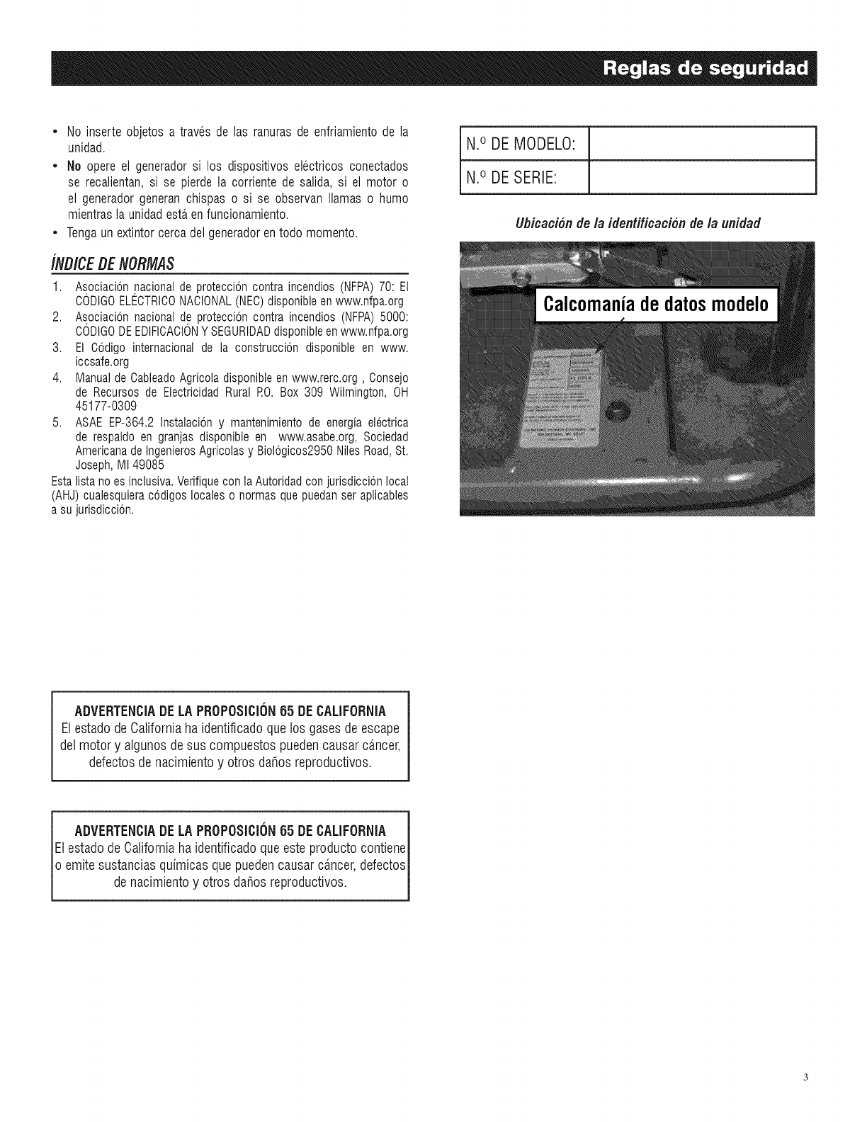
MODELNO:
SERIALNO:
Unit ID Location
CALIFORNIAPROPOSITION65 WARNING
Engineexhaustand someof its constituentsareknown
to the Stateof Californiato causecancer,birth defects
andother reproductiveharm.
CALIFORNIAPROPOSITION65 WARNING
This productcontains or emits chemicalsknown to the
Stateof Californiato causecancer,birth defectsand
other reproductiveharm.
1.1 UNPACKING
*Removeall packagingmaterial.
*Removethe generatorfrom carton.
*Removeseparateaccessory box.
NOTE:
Standard 20 poundLP cylinder(tank) is not included.
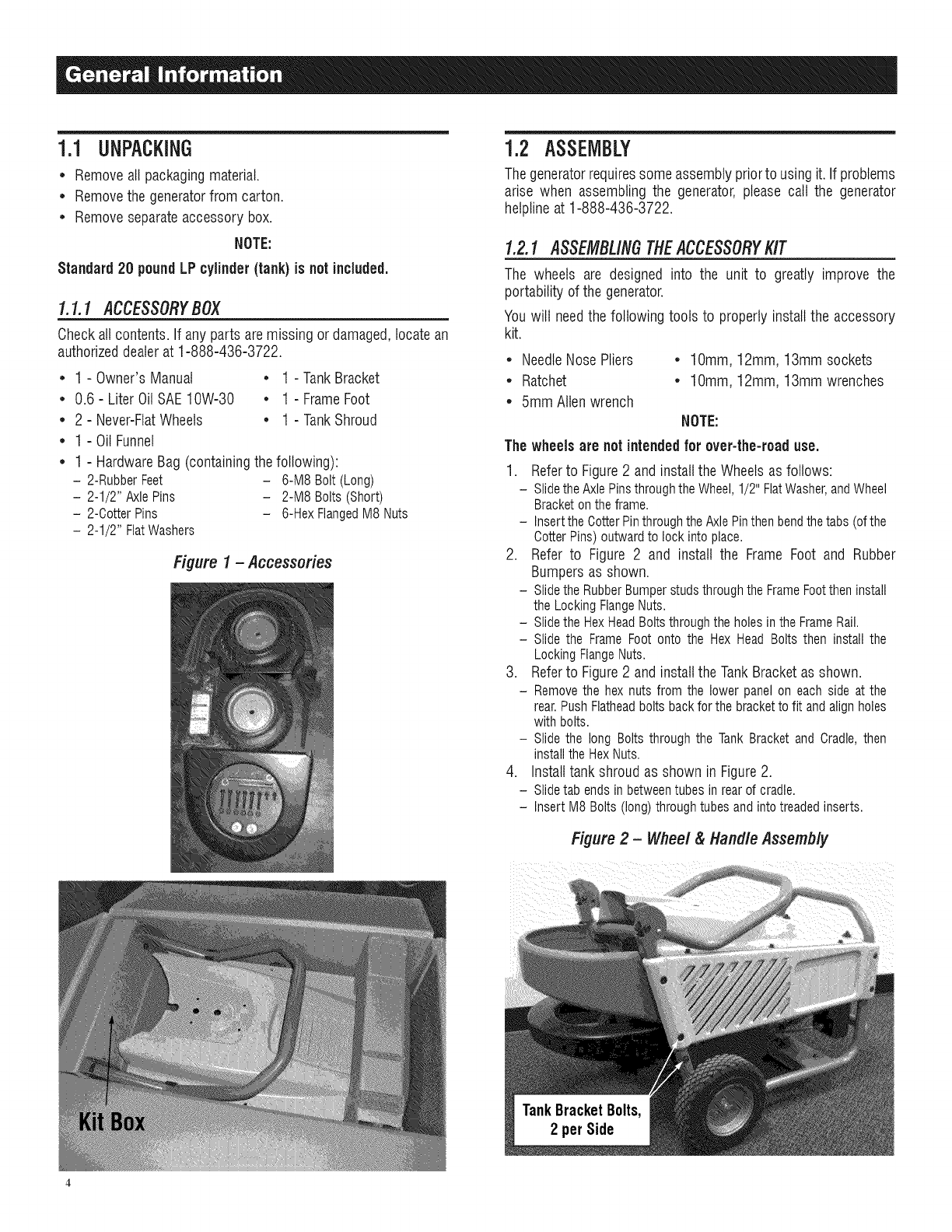
I.I.1 ACCESSORYBOX
Checkall contents. If any parts aremissing or damaged,locatean
authorizeddealerat 1-888-436-3722.
* 1 - Owner'sManual * 1 - TankBracket
* 0.6 - Liter OilSAE10W-30 * 1 - FrameFoot
* 2 - Never-FlatWheels • 1 - TankShroud
* 1 - Oil Funnel
* 1 - HardwareBag (containingthe following):
- 2-RubberFeet - 6-M8Bolt(Long)
- 2-1/2"AxlePins - 2-M8Bolts(Short)
-2-CotterPins -6-HexFlangedM8Nuts
- 2-1/2"FlatWashers
Figure 1 -Accessories
1.2 ASSEMBLY
Thegeneratorrequiressome assemblypriorto using it. If problems
arise when assembling the generator,please call the generator
hetplineat 1-888-436-3722.
1.2.1 ASSEMBLINGTHEACCESSORYKIT
The wheels are designed into the unit to greatly improve the
portability of the generator.
Youwilt needthe following tools to properly installthe accessory
kit.
* NeedleNosePliers * lOmm, 12mm, 13mm sockets
* Ratchet * lOmm, 12mm, 13mm wrenches
* 5mm Allen wrench
NOTE:
Thewheels are not intendedfor over-the-road use.
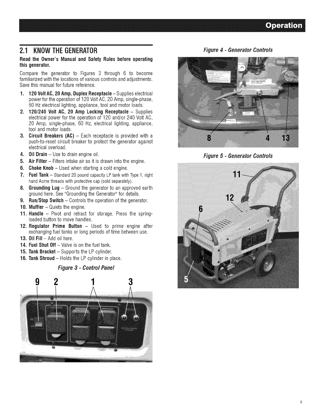
1. Refer to Figure 2 and install the Wheels as follows:
- Slidethe Axle Pinsthroughthe Wheel,1/2" FlatWasher,andWheel
Bracketon the frame.
- Insertthe CotterPinthroughthe Axle Pinthen bend thetabs (ofthe
CotterPins) outward to lock into place.
2. Refer to Figure 2 and install the Frame Foot and Rubber
Bumpers as shown.
- Slidethe RubberBumperstuds throughthe FrameFootthen install
the Locking FlangeNuts.
- Slidethe HexHeadBoltsthrough the holes in the FrameRail.
- Slide the Frame Foot onto the Hex Head Bolts then install the
Locking FlangeNuts.
3. Refer to Figure 2 and install the Tank Bracket as shown.
- Removethe hex nuts from the lower panel on each side at the
rear.Push Flatheadbolts back for the bracketto fit and alignholes
with bolts.
- Slide the long Bolts through the Tank Bracket and Cradle,then
install the HexNuts.
4. Install tank shroud as shown in Figure 2.
- Slidetab ends in betweentubes in rear of cradle.
- Insert M8 Bolts (long) throughtubes and intotreaded inserts.
Figure 2 - Wheel & Handle Assembly
2.1 KNOWTHEGENERATOR
Read the Owner'sIVlanualand Safety Rules before operating
thisgenerator.
Compare the generator to Figures 3 through 6 to become
familiarizedwith the locationsof variouscontrols andadjustments.
Savethis manualfor future reference.
1. 120 VoltAC,20 Amp,DuplexReceptacle-Supplieselectrical
powerfor the operationof 120VoltAC, 20 Amp,single-phase,
60 Hzelectrical lighting,appliance,tool and motor loads.
2. 120/240 Volt AC, 20 Amp LockingReceptacle- Supplies
electrical power for the operation of 120 and/or 240 Volt AC,
20 Amp, single-phase, 60 Hz, electrical lighting, appliance,
tool andmotor loads.
3. Circuit Breakers (AC) - Each receptacle is provided with a
push-to-resetcircuit breakerto protect the generatoragainst
electricaloverload.
4. Oil Drain- Useto drainengineoil.
5. Air Filter- Filters intakeair as it is drawn into the engine.
6. ChokeKnob- Usedwhen starting a cold engine.
7. Fuel Tank- Standard20poundcapacityLPtankwithType1, right
handAcmethreadswithprotectivecap(soldseparately).
8. Grounding Lug - Groundthe generatorto an approvedearth
groundhere. See"Groundingthe Generator"for details.
9. Run/Stop Switch- Controlsthe operationof the generator.
10. IViuffler- Quietsthe engine.
11. Handle - Pivot and retract for storage. Press the spring-
loadedbuttonto move handles.
12. Regulator Prime Button - Used to prime engine after
exchangingfuel tanks or long periodsof time betweenuse.
13. Oil Fill-Add oil here.
14. FuelShut Off - Valve is on the fuel tank.
15. TankBracket - Supportsthe LPcylinder.
18. TankShroud- Holdsthe LP cylinder in place.
Figure3 -Contro/Pane/
9213
Figure4- GeneratorControls
Figure 5 -GeneratorControls
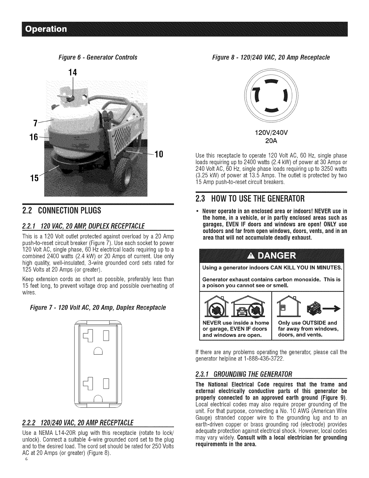
Figure 6 - Generator Contro/s
14
0
2.2 CONNECTIONPLUGS
2.2.1 120VAC,20 AMP,DUPLEXRECEPTACLE
This is a 120 Volt outlet protectedagainst overloadby a 20 Amp
push-to-resetcircuit breaker (Figure7). Useeach socketto power
120 Volt AO, single phase,60 Hzelectrical loads requiringupto a
combined 2400 watts (2.4 kW) or 20 Amps of current. Useonly
high quality, well-insulated, 3-wire grounded cord sets rated for
125 Volts at 20 Amps (or greater).
Keep extensioncords as short as possible, preferablyless than
15 feet long, to preventvoltage drop and possibleoverheatingof
wires.
Figure 7- 120 Volt AC, 20 Amp, Duplex Receptacle
2.2.2 120/240 VAC,20 AMPRECEPTACLE
Use a NEMA L14-20R plug with this receptacle (rotate to lock!
unlock). Oonnecta suitable4-wire groundedcord set to the plug
andto the desiredtoad.The cord set should be ratedfor 250 Volts
AC at 20 Amps (or greater)(Figure8).
6
Figure 8 - 120/240 VAC, 20 Amp Receptacle
120V/240V
20A
Use this receptacleto operate 120 Volt AC, 60 Hz, single phase
loads requiringup to 2400 watts (2.4 kW) of power at 30 Amps or
240 Volt AC,60 Hz, singlephase loadsrequiringup to 3250 watts
(3.25 kW) of power at 13.5 Amps. The outlet is protectedby two
15 Amp push-to-resetcircuit breakers.
2.3 HOW TO USETHEGENERATOR
Never operatein an enclosedarea or indoors!NEVERuse in
the home, in avehicle, or in partly enclosed areas suchas
garages,EVEN IF doorsand windows are open! ONLYuse
outdoors and far from open windows,doors,vents,and inan
area that will not accumulate deadly exhaust.
Using agenerator indoors CAN KILL YOU IN MINUTES.
Generator exhaust contains carbon monoxide. This is
apoison you cannot see or smell,
NEVER use insideahome
or garage, EVEN IF doors
and windows are open.
Only use OUTSIDE and
far away from windows,
doors, and vents.
If there are any problems operatingthe generator,pleasecall the
generatorhelplineat 1-888-436-3722.
2.3.1 GROUNDINGTHEGENERATOR
The National Electrical Code requires that the frame and
external electrically conductive parts of this generator be
properlyconnectedto an approved earth ground (Figure g).
Local electrical codes may also require proper grounding of the
unit. Forthat purpose,connectinga No. 10 AWG (AmericanWire
Gauge) stranded copper wire to the grounding lug and to an
earth-driven copper or brass grounding rod (electrode) provides
adequateprotectionagainstelectricalshock. However,local codes
may vary widely. Consultwith a local electrician for grounding
requirementsin the area.
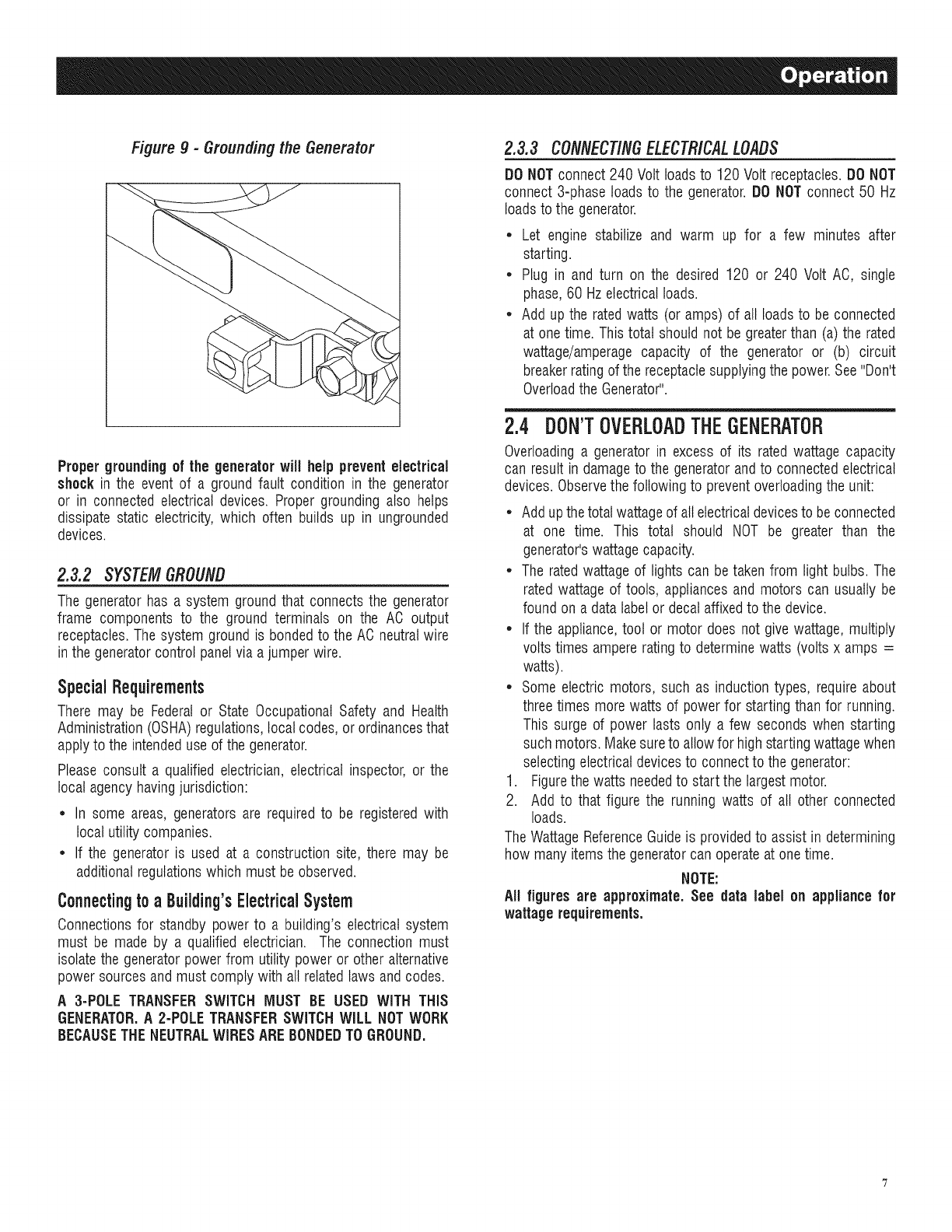
Figure g - Grounding the Generator
Propergroundingof the generatorwill help preventelectrical
shockin the event of a ground fault condition in the generator
or in connected electrical devices. Proper grounding also helps
dissipate static electricity, which often builds up in ungrounded
devices.
2.3.2 SYSTEMGROUND
The generator has a system groundthat connectsthe generator
frame components to the ground terminals on the AC output
receptacles.The system groundis bondedto the AC neutralwire
in the generatorcontrol panelvia a jumper wire.
SpecialRequirements
There may be Federalor State Occupational Safety and Health
Administration(OSHA)regulations,local codes, or ordinancesthat
apply to the intendeduse of the generator.
Please consult a qualified electrician,electrical inspector, or the
local agencyhavingjurisdiction:
,, In some areas, generators are requiredto be registeredwith
local utility companies.
*If the generator is used at a construction site, there may be
additionalregulationswhich must be observed.
Connectingtoa Buiiding'sElectricalSystem
Oonnectionsfor standby power to a building's electrical system
must be made by a qualified electrician. The connection must
isolatethe generatorpower from utility power or other alternative
power sources and must comply with all relatedlaws andcodes.
A 3-POLE TRANSFERSWITCH MUST BE USED WiTH THiS
GENERATOR.A 2-POLETRANSFERSWITCHWILL NOTWORK
BECAUSETHENEUTRALWIRESAREBONDEDTOGROUND.
2.3.3 CONNECTINGELECTRICALLOADS
DO NOTconnect 240 Volt loadsto 120 Volt receptacles.DONOT
connect 3-phase loads to the generator.DO NOTconnect 50 Hz
loads to the generator.
•Let engine stabilize and warm up for a few minutes after
starting.
•Plug in and turn on the desired 120 or 240 Volt AO, single
phase,60 Hzelectrical loads.
•Add up the ratedwatts (or amps) of all loadsto be connected
at onetime. This total should not be greaterthan (a) the rated
wattage/amperage capacity of the generator or (b) circuit
breakerratingof the receptaclesupplyingthe power.See"Don't
Overloadthe Generator".
2.4 DON'TOVERLOADTHEGENERATOR
Overloadinga generator in excess of its rated wattage capacity
can result in damageto the generatorandto connectedelectrical
devices.Observethe following to preventoverloadingthe unit:
•Addupthe total wattageof all electricaldevicesto be connected
at one time. This total should NOT be greater than the
generator'swattage capacity.
•The ratedwattage of lights can betaken from light bulbs. The
rated wattage of tools, appliancesand motors can usually be
found on a data labelor decal affixedto the device.
•If the appliance,tool or motor does not give wattage,multiply
volts times ampererating to determinewatts (volts x amps =
watts).
•Some electric motors, such as induction types, require about
threetimes more watts of power for starting than for running.
This surge of power lasts only a few seconds when starting
suchmotors. Makesureto allowfor high startingwattagewhen
selectingelectrical devicesto connect to the generator:
1. Figurethe watts neededto start the largestmotor.
2. Add to that figure the running watts of all other connected
loads.
The WattageReferenceGuideis providedto assist in determining
how many items the generatorcan operateat onetime.
NOTE:
All figures are approximate. See data label on appliance for
wattage requirements.
2.5 WATTAGEREFERENCEGUIDE
Device................................... RunningWatts
*Air Conditioner (12,000 Btu).......................... 1700
*Air Conditioner (24,000 Btu).......................... 3800
*Air Conditioner (40,000 Btu).......................... 6000
Battery Charger(20 Amp).............................. 500
BeltSander (3") .................................... 1000
ChainSaw ........................................ 1200
Circular Saw (6-1/2") ........................... 800 to 1000
*Clothes Dryer (Electric) ............................. 5750
*Clothes Dryer (Gas) ................................. 700
*Clothes Washer ................................... 1150
CoffeeMaker ...................................... 1750
*Compressor (1 HP)................................. 2000
*Compressor (3/4 HP) ............................... 1800
*Compressor (1/2 HP) ............................... 1400
Curling Iron......................................... 700
*Dehumidifier....................................... 650
Disc Sander(9").................................... 1200
EdgeTrimmer....................................... 500
Electric Blanket...................................... 400
Electric NailGun.................................... 1200
Electric Range(per element)........................... 1500
Electric Skillet...................................... 1250
*Freezer ............................................ 700
*Furnace Fan(3/5 HP) ................................ 875
*GarageDoor Opener............................ 500 to 750
Hair Dryer......................................... 1200
Hand Drill.................................... 250 to 1100
HedgeTrimmer...................................... 450
Impact Wrench...................................... 500
Iron.............................................. 1200
*Jet Pump ......................................... 800
Lawn Mower....................................... 1200
Light Bulb.......................................... 1O0
Microwave Oven............................... 700 to 1000
*Milk Cooler....................................... 1100
OilBurner on Furnace................................. 300
Oil FiredSpace Heater (140,000 Btu) ..................... 400
Oil FiredSpace Heater (85,000 Btu) ...................... 225
Oil FiredSpace Heater (30,000 Btu) ...................... 150
*Paint Sprayer,Airless (1/3 HP) ......................... 600
PaintSprayer,Airless (handheld)......................... 150
Radio......................................... 50 to 200
*Refrigerator........................................ 700
Slow Cooker........................................ 200
*Submersible Pump (1-1/2 HP) ........................ 2800
*Submersible Pump (1 HP) ........................... 2000
*Submersible Pump (1/2 HP).......................... 1500
*Sump Pump ................................. 800 to 1050
*Table Saw (10") ............................. 1750 to 2000
Television..................................... 200 to 500
Toaster..................................... 1000 to 1650
WeedTrimmer ...................................... 500
* Allow 3 times the listed watts for starting these devices.
2.6 BEFORESTARTINGTHEGENERATOR
Priorto operatingthe generator,engineoil and LPfuel will needto
be added,as follows:
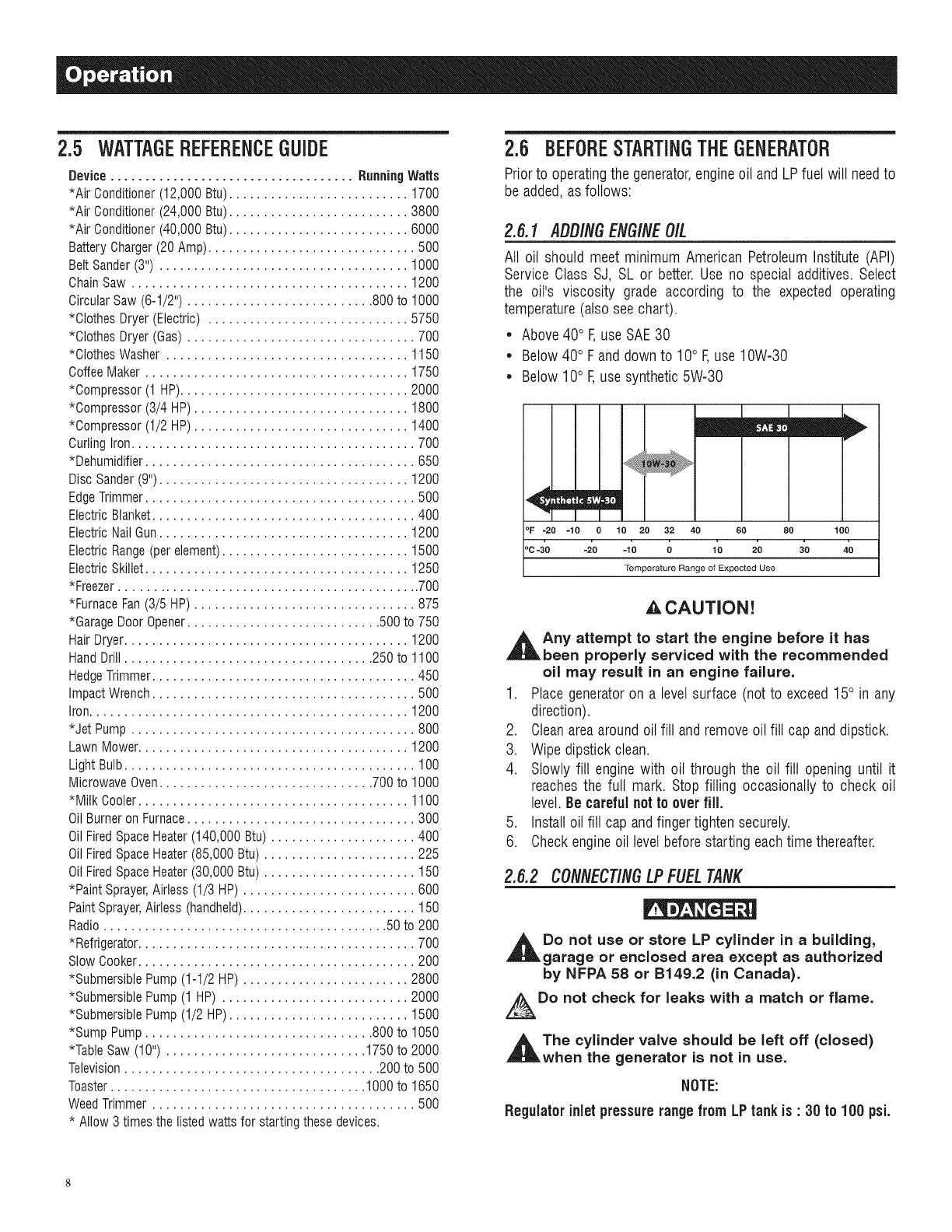
2.6.1 AOO/NGENGINEOIL
All oil should meet minimum American PetroleumInstitute (API)
Service Class SJ, SL or better. Use no special additives. Select
the oil's viscosity grade according to the expected operating
temperature(also see chart).
• Above40° F,use SAE30
• Below 40° F and down to 10° F,use 10W-30
• Below 10° F,use synthetic5W-30
°F =20 =10 010 20 32 40 60
'c4'o -2'0 -lo 0 lo 2o
Temperature Range of Expected Use
80 100
,&CAUTION!
_t ny attempt to start the engine before it has
been properly serviced with the recommended
oil may result in an engine failure.
1. Place generatoron a levelsurface (not to exceed15° in any
direction).
2. Cleanareaaroundoil fill andremoveoil fill cap anddipstick.
3. Wipe dipstick clean.
4. Slowly fill engine with oil through the oil fill opening until it
reachesthe full mark. Stop filling occasionally to check oil
level.Be careful not to overfill.
5. Install oil fill cap andfinger tighten securely.
6. Checkengineoil levelbefore starting eachtime thereafter.
2.6.2 CONNECTINGLPFUELTANK
Do not use or store LP cylinder in a building,
garage or enclosed area except as authorized
by NFPA 58 or B149.2 (in Canada).
Do not check for leaks with a match or flame.
,_The cylinder valve should be left off (closed)
when the generator is not in use.
NOTE:
Regulator inlet pressurerangefrom LPtank is :30 to 100 psi.
• Use only standard 20 or 30 pound capacity LP tanks with
Type1, right hand Acmethreadswith this generator.Verifythe
requalification date on the tank has not expired. Do not use
rusted or damagedcylinders.
• All new cylinders must be purgedof air and moisture prior to
filling. Usedcylindersthat havenot beenpluggedor keptclosed
must also be purged.
• The purging process should be done by your propane gas
supplier. (Cylinders from an exchangesupplier should have
beenpurgedandfilled properly already)
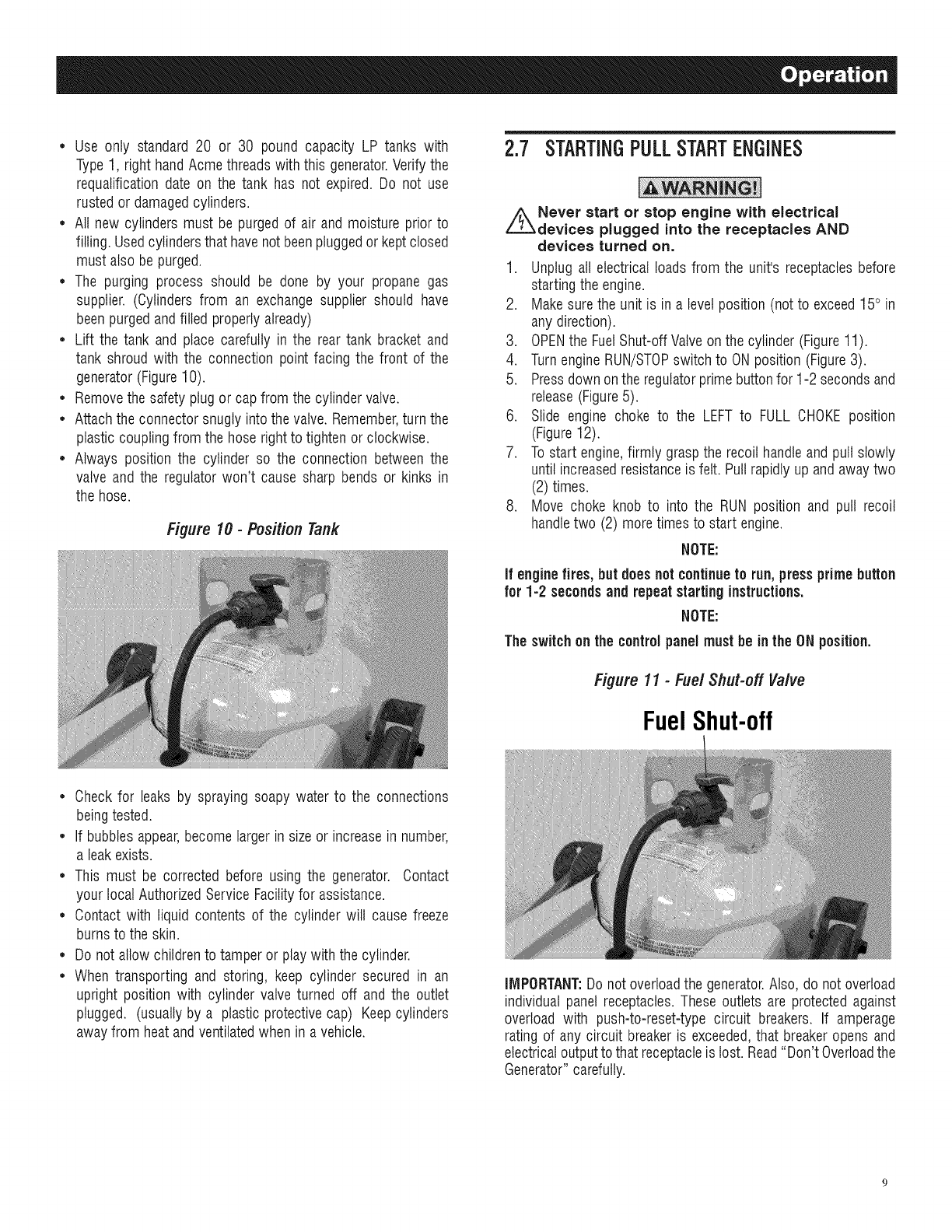
• Lift the tank and place carefully in the rear tank bracket and
tank shroud with the connection point facing the front of the
generator(Figure10).
• Removethe safety plugor cap from the cylinder valve.
• Attachthe connector snugly into the valve. Remember,turn the
plastic coupling from the hose rightto tighten or clockwise.
• Always position the cylinder so the connection between the
valve and the regulatorwon't cause sharp bends or kinks in
the hose.
Figure 10 -Position Tank
2.7 STARTINGPULLSTARTENGINES
//_Never start or stop engine with electrical
devices plugged into the receptacles AND
devices turned on.
1. Unplug all electrical loads from the unit's receptaclesbefore
starting the engine.
2. Makesure the unit is in a level position (not to exceed15° in
any direction).
3. OPENthe FuelShut-off Valveon the cylinder (Figure11).
4. TurnengineRUN/STOPswitch to ONposition (Figure3).
5. Pressdown onthe regulatorprime buttonfor 1-2 secondsand
release(Figure5).
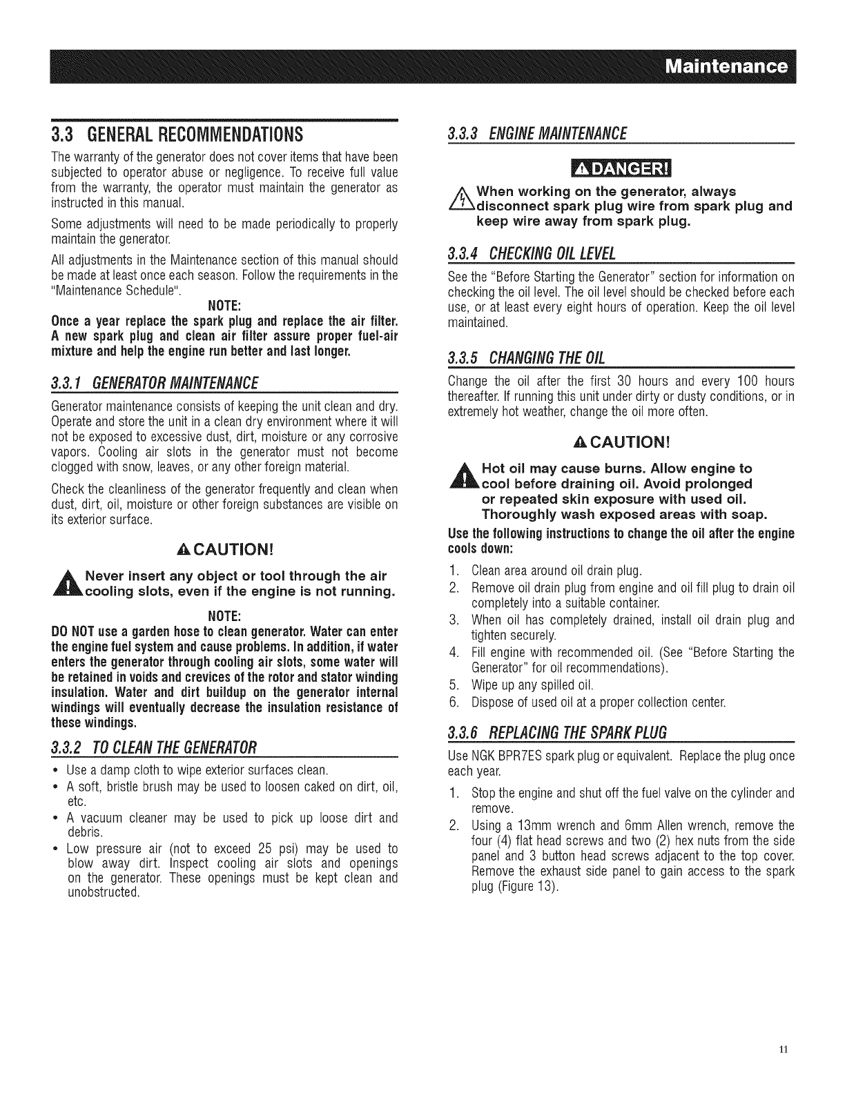
6. Slide engine choke to the LEFT to FULL CHOKEposition
(Figure12).
7. To start engine,firmly graspthe recoil handleandpull slowly
until increasedresistanceis felt. Pullrapidly up and awaytwo
(2) times.
8. Move choke knob to into the RUN position and pull recoil
handletwo (2) moretimes to start engine.
NOTE:
If enginefires, but does not continueto run, pressprimebutton
for 1-2 seconds and repeat starting instructions.
NOTE:
Theswitch on the controlpanel must be in the ON position.
Figure 11 -Fuel Shut-off Valve
FuelShut-off
• Check for leaks by spraying soapy water to the connections
beingtested.
• If bubblesappear,becomelargerin size or increasein number,
a leak exists.
• This must be corrected before using the generator. Contact
your local AuthorizedServiceFacilityfor assistance.
• Contact with liquid contents of the cylinder will cause freeze
burns to the skin.
• Do not allow childrento tamper or play with the cylinder.
• When transporting and storing, keep cylinder secured in an
upright position with cylinder valve turned off and the outlet
plugged. (usuallyby a plastic protectivecap) Keepcylinders
awayfrom heat andventilatedwhen in a vehicle.
IMPORTANT:Do not overloadthe generator.Also, do not overload
individual panel receptacles.These outlets are protected against
overload with push-to-reset-type circuit breakers. If amperage
rating of any circuit breakeris exceeded,that breakeropens and
electricaloutputto that receptacleis lost. Read"Don't Overloadthe
Generator"carefully.
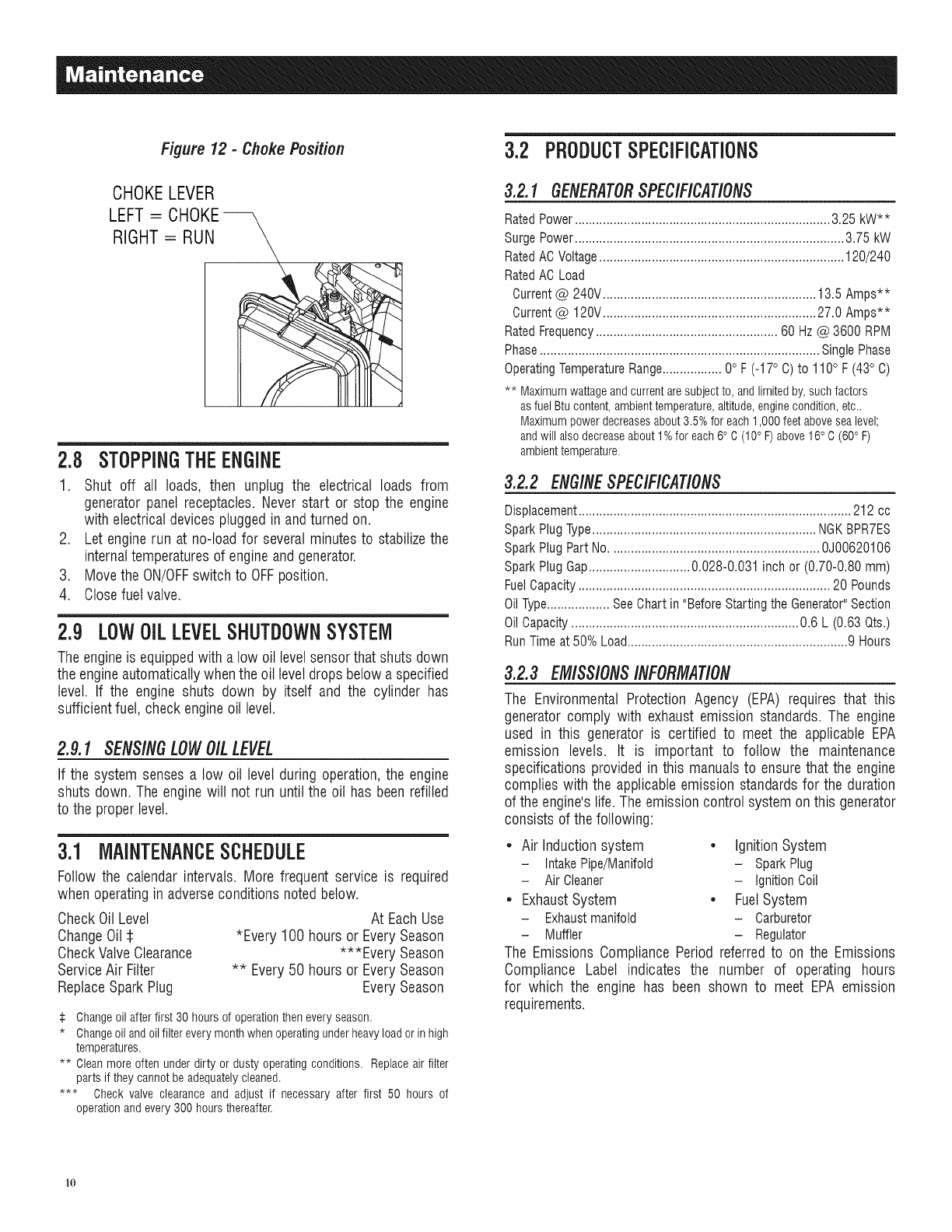
Figure 12 - Choke Position
CHOKELEVER
LEFT = CHOKE--
RIGHT = RUN
2.8 STOPPINGTHEENGINE
1. Shut off all loads, then unplug the electrical loads from
generator panel receptacles. Never start or stop the engine
with electrical devices pluggedin andturned on.
2. Let enginerun at no-load for severalminutes to stabilizethe
internaltemperaturesof engineand generator.
3. Movethe ON/OFFswitch to OFFposition.
4. Closefuel valve.
2.9 LOWOiLLEVELSHUTDOWNSYSTEM
The engineis equippedwith a low oil levelsensorthat shuts down
the engineautomaticallywhenthe oil leveldrops below a specified
level. If the engine shuts down by itself and the cylinder has
sufficient fuel, check engineoil level.
2.9.1 SENSINGLOWOILLEVEL
If the system senses a low oil level during operation,the engine
shuts down. The enginewill not run until the oil has beenrefilled
to the properlevel.
3.1 MAINTENANCESCHEDULE
Follow the calendar intervals. More frequent service is required
when operatingin adverseconditions noted below.
CheckOil Level
ChangeOil
CheckValveClearance
ServiceAir Filter
ReplaceSpark Plug
At Each Use
*Every 100 hours or EverySeason
***Every Season
** Every50 hours or EverySeason
EverySeason
:i: Changeoil after first 30 hours of operationthen every season.
* Changeoiland oil filter every monthwhen operatingunder heavyload or in high
temperatures.
** Cleanmore often under dirty or dusty operating conditions. Replace air filter
parts if they cannot be adequatelycleaned.
*** Check valve clearance and adjust if necessary after first 50 hours of
operationand every300 hours thereafteK
3.2 PRODUCTSPECIFiCATiONS
3.2.1 GENERATORSPECIFICATIONS
RatedPower......................................................................... 3.25 kW**
Surge Power............................................................................. 3.75 kW
RatedACVoltage...................................................................... 120/240
RatedAC Load
Current@ 240V............................................................. 13.5 Amps**
Current@ 120V............................................................. 27.0 Amps**
RatedFrequency.................................................... 60 Hz@ 3600 RPM
Phase................................................................................ SinglePhase
OperatingTemperatureRange................. 0° F(-17° C) to 110° F(43° C)
** Maximumwattageandcurrentaresubjectto, andlimitedby,suchfactors
asfuelBtucontent,ambienttemperature,altitude,enginecondition,etc..
Maximumpowerdecreasesabout3.5%for each1,000feetabovesealevel;
andwillalsodecreaseabout1%for each6° C (10° F)above16° C(60° F)
ambienttemperature.
3.2.2 ENG/NESPECIFICATIONS
Displacement.............................................................................. 212 cc
SparkPlugType................................................................ NGKBPR7ES
Spark Plug Part No............................................................ 0J00620106
SparkPlug Gap............................. 0.028-0.031 inch or (0.70-0.80 mm)
FuelCapacity........................................................................ 20 Pounds
Oil Type.................. SeeChart in "Before Starting the Generator"Section
OilCapacity................................................................. 0.6 L (0.63 Qts.)
Run Time at 50% Load............................................................... 9 Hours
3.2.3 EMISSIONSINFORMATION
The Environmental Protection Agency (EPA) requires that this
generator comply with exhaust emission standards. The engine
used in this generator is certified to meet the applicable EPA
emission levels. It is important to follow the maintenance
specifications provided in this manualsto ensurethat the engine
complies with the applicableemission standardsfor the duration
of the engine'slife. The emissioncontrol system onthis generator
consists of the following:
• Air Induction system • Ignition System
- IntakePipe/Manifold - SparkPlug
- Air Cleaner - Ignition Coil
• Exhaust System • Fuel System
- Exhaustmanifold - Carburetor
- Muffler - Regulator
The Emissions Compliance Period referred to on the Emissions
Compliance Label indicates the number of operating hours
for which the engine has been shown to meet EPA emission
requirements.
1o
3.3 GENERALRECOIVliViENDATiONS
Thewarranty of the generatordoes not cover items thathave been
subjected to operator abuse or negligence.To receive full value
from the warranty, the operator must maintain the generator as
instructed inthis manual.
Some adjustments will needto be made periodicallyto properly
maintainthe generator.
All adjustments in the Maintenancesection of this manual should
bemade at leastonce each season.Followthe requirementsin the
"MaintenanceSchedule".
NOTE:
Once a year replace the sparkplug and replace the air filter.
A new spark plug and clean air filter assure proper fuel-air
mixtureandhelp the engine run better andlast longer.
3.3.1GENERATOR/V/A/NTENANCE
Generatormaintenanceconsists of keepingthe unit clean and dry.
Operateand storethe unit in a clean dry environmentwhere it will
not be exposedto excessivedust, dirt, moisture or any corrosive
vapors. Cooling air slots in the generator must not become
clogged with snow, leaves,or any other foreign material.
Checkthe cleanlinessof the generatorfrequently andclean when
dust, dirt, oil, moisture or other foreign substances arevisible on
its exteriorsurface.
_,CAUTION!
,_ Never insert any object or tool through the air
cooling slots, even if the engine is not running.
NOTE:
DO NOTuse a garden hoseto cleangenerator. Water can enter
the enginefuelsystemand causeproblems.In addition,if water
enters the generator throughcoolingair slots,some water will
be retained invoidsand crevicesof the rotorand stator winding
insulation.Water and dirt buildup on the generator internal
windingswill eventually decrease the insulationresistanceof
thesewindings.
3.3.2 TOCLEANTHEGENERATOR
*Usea damp cloth to wipe exteriorsurfaces clean.
*A soft, bristle brush may be used to loosen caked on dirt, oil,
etc.
*A vacuum cleaner may be used to pick up loose dirt and
debris.
*Low pressure air (not to exceed 25 psi) may be used to
blow away dirt. Inspect cooling air slots and openings
on the generator.These openings must be kept clean and
unobstructed.
3.3.3 ENGINEMAINTENANCE
When working on the generator, always
disconnect spark plug wire from spark plug and
keep wire away from spark plug.
3.3.4 CHECKINGOILLEVEL
Seethe "BeforeStartingthe Generator"sectionfor informationon
checkingthe oil level.The oil levelshould be checkedbefore each
use, or at least every eight hours of operation.Keepthe oil level
maintained.
3.3.5 CHANG/NGTHEO/L
Change the oil after the first 30 hours and every 100 hours
thereafter.If runningthis unit underdirty or dusty conditions,or in
extremelyhot weather,changethe oil more often.
,A.CAUTION!
,_Hot oil may cause burns. Allow engine to
cool before draining oil. Avoid prolonged
or repeated skin exposure with used oil.
Thoroughly wash exposed areas with soap.
Use thefollowing instructionsto changethe oil afterthe engine
coolsdown:
1. Cleanareaaroundoil drainplug.
2. Removeoil drain plug from engineandoil fill plugto drainoil
completelyinto a suitablecontainer.
3. When oil has completely drained, install oil drain plug and
tightensecurely.
4. Fill enginewith recommended oil. (See "Before Starting the
Generator"for oil recommendations).
5. Wipe up any spilled oil.
6. Disposeof used oil at a propercollection center.
3.3.6 REPLACINGTHESPARKPLUG
UseNGKBPR7ESsparkplugor equivalent. Replacethe plug once
each year.
.
2.
Stopthe engineand shut off the fuel valve onthe cylinderand
remove.
Using a 13mm wrench and 6mm Allen wrench, removethe
four (4) flat headscrews andtwo (2) hex nutsfrom the side
panel and 3 button head screws adjacentto the top cover.
Removethe exhaust side panel to gain access to the spark
plug (Figure13).
11
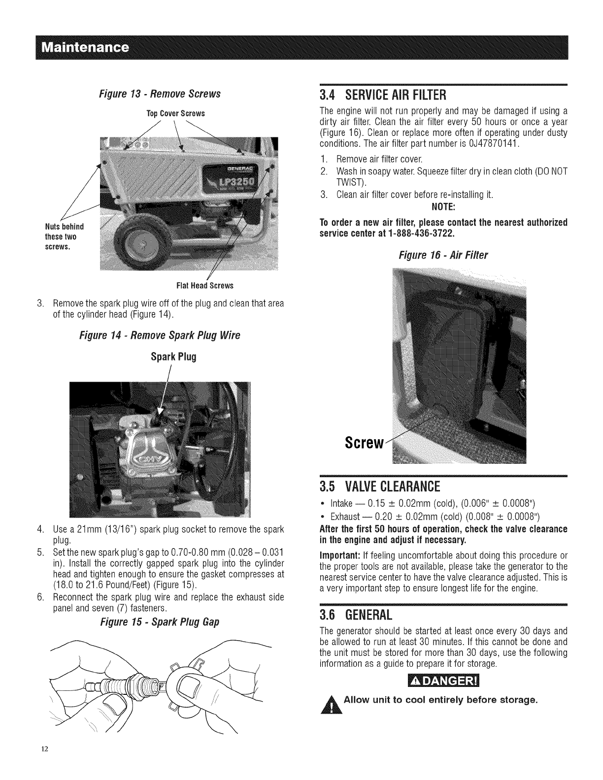
Nutsbehind
thesetwo
screws,
Figure 13 - Remove Screws
TopCoverScrews
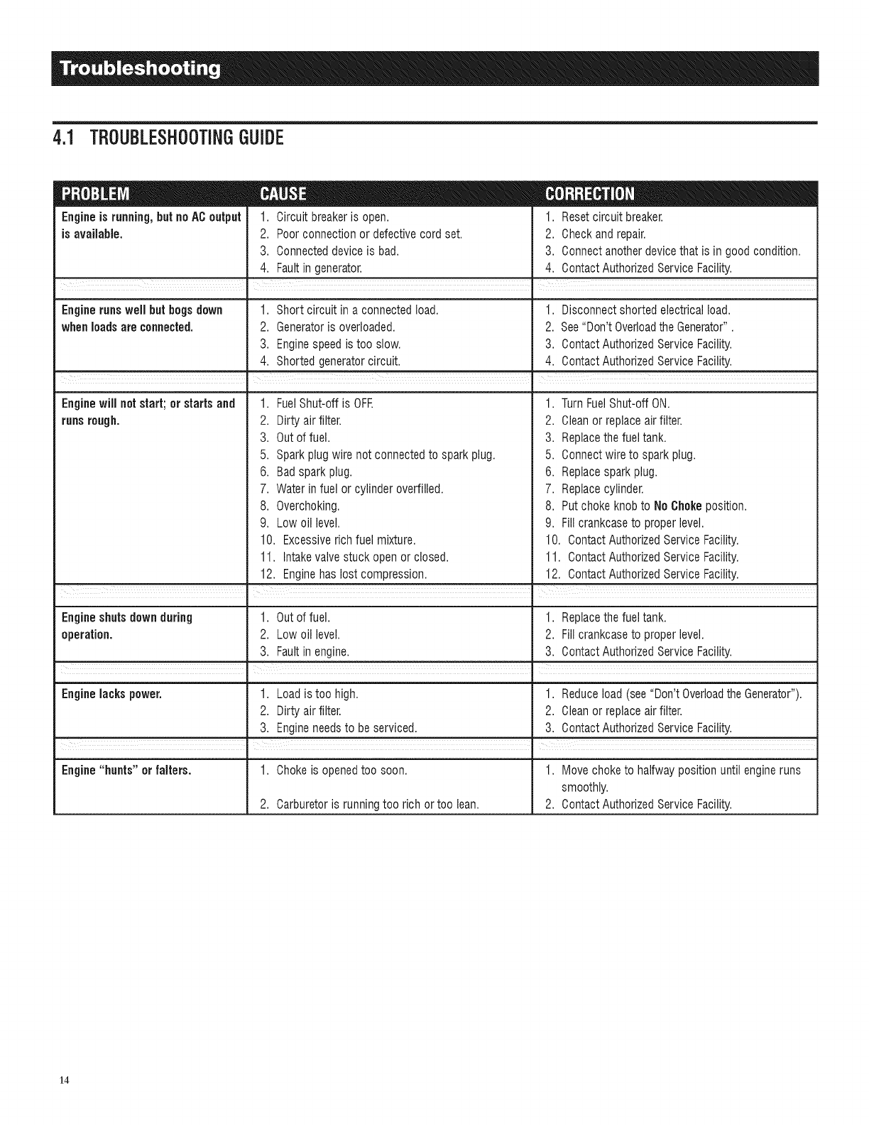
3.4 SERVICEAiRFILTER
The enginewill not run properly and may be damagedif using a
dirty air filter. Cleanthe air filter every 50 hours or once a year
(Figure 16). Clean or replacemore often if operatingunder dusty
conditions.The air filter part numberis 0J47870141.
1. Removeairfilter cover.
2. Washinsoapywater.Squeezefilter dry in cleancloth (DONOT
TWIST).
3. Cleanair filter cover before reqnstallingit.
NOTE:
Toorder a new air filter, pleasecontactthe nearestauthorized
service centerat 1-888-435-3722.
Figure 16 -Air Filter
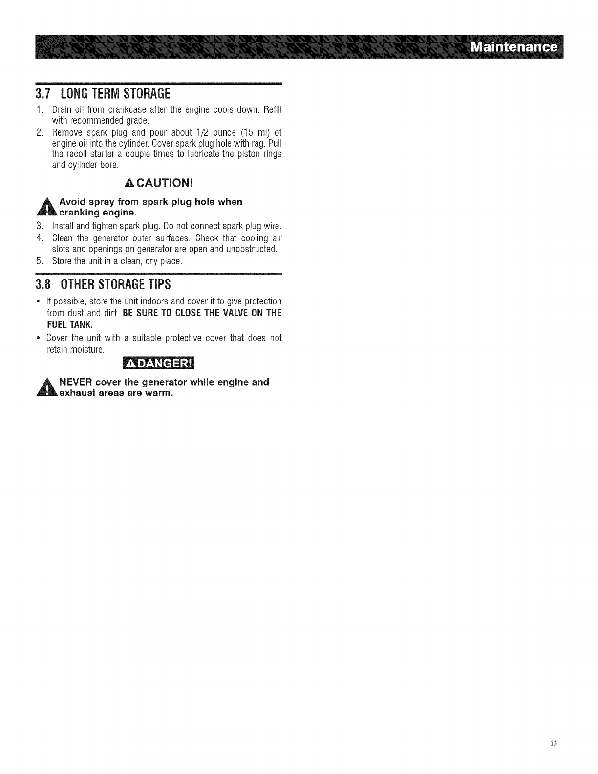
.
FlatHeadScrews
Removethe spark plugwire off of the plugand cleanthat area
of the cylinder head(Figure14).
Figure 14 -Remove Spark Plug Wire
SparkPlug
4. Usea 21mm (13/16") sparkplug socketto removethe spark
plug.
5. Setthe new sparkplug's gapto 0.70-0.80 mm (0.028- 0.031
in). Install the correctly gapped spark plug into the cylinder
headandtighten enoughto ensurethe gasket compressesat
(18.0 to 21.6 Pound/Feet)(Figure15).
6. Reconnectthe spark plug wire and replacethe exhaustside
panelandseven (7) fasteners.
Figure 15 -Spark Plug Gap
3.5 VALVECLEARANCE
*Intake-- 0.15 _+O.02mm (cold), (0.006" _ 0.0008")
* Exhaust-- 0.20 _+O.02mm (cold) (0.008" _+0.0008")
Afterthe first 50 hoursof operation,checkthe valve clearance
in the engineand adjust if necessary.
important:If feeling uncomfortableabout doing this procedureor
the proper tools are not available,pleasetakethe generatorto the
nearestservice centerto havethe valveclearanceadjusted.Thisis
a very important stepto ensurelongestlife for the engine.
3.6 GENERAL
The generatorshould be started at least once every 30 days and
be allowed to run at least30 minutes. If this cannot be done and
the unit must be stored for more than 30 days, use the following
information as a guideto prepareit for storage.
,_AIIow unit to cool entirely before storage.
12
3.7 LONGTERMSTORAGE
1. Drain oil from crankcaseafter the engine cools down. Refill
with recommendedgrade.
2. Remove spark plug and pour about 1/2 ounce (15 mt) of
engineoil into the cylinder.Coverspark plugholewith rag.Putt
the recoil starter a couple times to lubricatethe piston rings
and cylinderbore.
_CAUTION!
_1 void spray from spark plug hole when
cranking engine.
3. Install andtightenspark plug. Do not connect sparkplugwire.
4. Clean the generator outer surfaces. Check that cooling air
slots andopenings on generatorareopen and unobstructed.
5. Storethe unit in a clean, dry place.
3.8 OTHERSTORAGETiPS
* If possible,storethe unit indoors andcover it to give protection
from dust and dirt. BESURETO CLOSETHE VALVEON THE
FUELTANK.
*Cover the unit with a suitable protective cover that does not
retain moisture.
_t NEVER cover the generator while engine and
exhaust areas are warm,
13
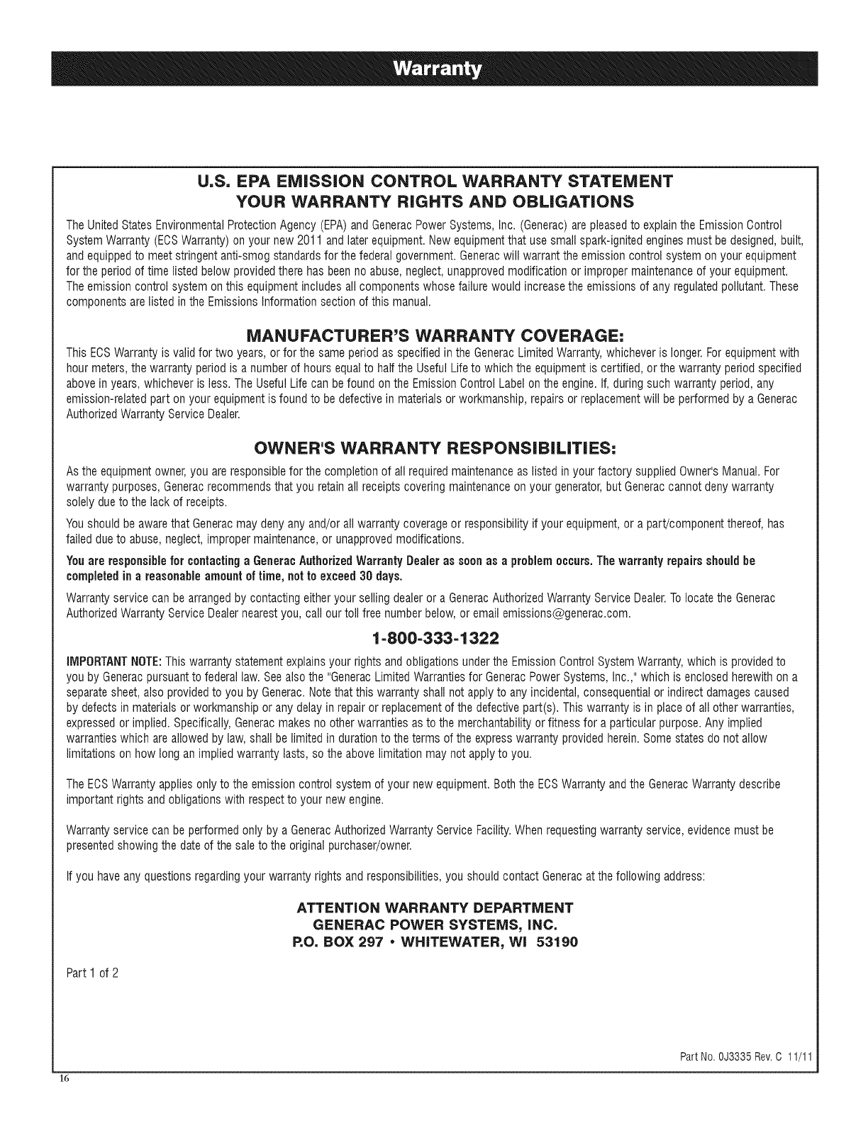
4.1 TBOUBLESHOOTINGGUIDE
Engine is running,but noACoutput 1. Circuit breakeris open. 1. Resetcircuit breaker.
is available. 2. Poor connection or defectivecord set. 2. Check and repair.
3. Connecteddevice is bad. 3. Connectanotherdevicethat is in good condition.
4. Faultin generator. 4. Contact AuthorizedService Facility.
i
Engine runswell hut bogs down 1. Short circuit in a connected load. 1. Disconnect shorted electrical load.
whenloads are connected. 2. Generatoris overloaded. 2. See"Don't Overloadthe Generator".
3. Enginespeed is too slow. 3. Contact AuthorizedService Facility.
4. Shorted generatorcircuit. 4. Contact AuthorizedService Facility.
Enginewill not start; or starts and 1. FuelShut-off is OFF. 1. Turn FuelShut-off ON.
runsrough. 2. Dirty air filter. 2. Cleanor replaceair filter.
3. Out offuel. 3. Replacethe fuel tank.
5. Sparkplug wire not connectedto spark plug. 5. Connectwire to spark plug.
6. Badspark plug.
7. Water in fuel or cylinder overfilled.
8. Overchoking.
9. Low oil level.
10. Excessiverich fuel mixture.
11. Intakevalve stuck open or closed.
12. Enginehas lost compression.
6. Replacespark plug.
7. Replacecylinder.
8. Put choke knobto No Chokeposition.
9. Fill crankcaseto proper level.
10. ContactAuthorizedService Facility.
11. ContactAuthorizedService Facility.
12. ContactAuthorizedService Facility.
Engineshuts down during 1. Out of fuel. 1. Replacethe fuel tank.
operation. 2. Low oil level. 2. Fill crankcaseto proper level.
3. Faultin engine. 3. Contact AuthorizedService Facility.
Engine lacks power. 1. Load is too high. 1. Reduceload (see"Don't Overloadthe Generator").
2. Dirty air filter. 2. Cleanor replaceair filter.
3. Engineneedsto be serviced. 3. Contact AuthorizedService Facility.
Engine "hunts" or falters. 1. Chokeis openedtoo soon. 1. Move choke to halfway position until engineruns
smoothly.
2. Carburetoris running too rich or too lean. 2. Contact AuthorizedServiceFacility.
14

15
U,S, EPA EMiSSiON CONTROL WARRANTY STATEMENT
YOUR WARRANTY RIGHTS AND OBLiGATiONS
TheUnited StatesEnvironmentalProtectionAgency (EPA)and GeneracPower Systems, Inc. (Generac)are pleasedto explainthe Emission Control
SystemWarranty (ECSWarranty) on your new 2011 and later equipment.New equipmentthat use small spark-ignited enginesmust bedesigned, built,
andequipped to meet stringent anti-smog standardsfor the federal government.Generacwill warrant the emission control system on your equipment
for the period of time listed below provided there has beenno abuse, neglect, unapprovedmodification or improper maintenance of your equipment.
Theemission control system on this equipmentincludes all components whose failurewould increasethe emissions of anyregulatedpollutant. These
componentsare listed in the Emissions Information section of this manual.
MANUFACTURER'S WARRANTY COVERAGE:
This ECSWarranty is validfor two years, or for the same period as specifiedin the GeneracLimitedWarranty,whicheveris longer. Forequipmentwith
hourmeters, the warranty period is a number of hours equalto half the Useful Lifeto which the equipmentis certified, or the warranty period specified
abovein years, whicheveris less. The Useful Life can be found on the EmissionControl Label on the engine.If, during suchwarranty period, any
emission-relatedpart on your equipment is found to be defectivein materials or workmanship, repairs or replacementwill be performed by a Generac
AuthorizedWarrantyService Dealer.
OWNER'S WARRANTY RESPONSiBiLiTiES:
As the equipmentowner,you are responsiblefor the completion of all requiredmaintenanceas listed in your factory supplied Owner'sManual.For
warranty purposes,Generacrecommendsthat you retainall receiptscovering maintenanceon your generator,but Generaccannotdeny warranty
solely dueto the lack of receipts.
Youshould be aware that Generacmay deny anyand/or all warranty coverage or responsibility if your equipment,or a part!component thereof,has
failed due to abuse,neglect, improper maintenance,or unapprovedmodifications.
Youare responsible for contactingaGeneracAuthorizedWarrantyDealer as soonasaproblemoccurs.Thewarranty repairsshouldbe
completed in a reasonable amount of time, not to exceed 30 days.
Warranty service can bearrangedby contacting eitheryour selling dealeror a GeneracAuthorizedWarranty ServiceDealer.Tolocate the Generac
AuthorizedWarrantyServiceDealernearest you, call our toll free numberbelow, or email emissions@generac.com.
1-800-333-1322
IMPORTANTNOTE:This warranty statementexplainsyour rights and obligationsunder the Emission Control System Warranty,which is providedto
you by Generacpursuantto federal law. Seealso the "GeneracLimited Warrantiesfor GeneracPower Systems,Inc.," which is enclosedherewith on a
separatesheet,also providedto you by Generac.Notethat this warranty shall not apply to any incidental,consequentialor indirect damagescaused
by defects in materials or workmanship or any delayin repairor replacementof the defectivepart(s). This warranty is in place of all other warranties,
expressedor implied. Specifically,Generacmakes no other warrantiesas to the merchantability or fitness for a particular purpose.Any implied
warrantieswhich areallowed by law, shall be limited in durationto the terms of the expresswarranty provided herein.Somestates do not allow
limitations on how long an implied warranty lasts, so the abovelimitation may not applyto you.
TheECSWarranty appliesonly to the emission control system of your new equipment. Boththe ECSWarranty andthe GeneracWarranty describe
important rights and obligationswith respectto your new engine.
Warranty service can be performed only by a GeneracAuthorizedWarrantyService Facility.When requestingwarranty service, evidencemust be
presentedshowingthe date of the saleto the originalpurchaser/owner.
If you have any questionsregardingyour warranty rights and responsibilities,you should contact Generacatthe following address:
ATTENTION WARRANTY DEPARTMENT
GENERAC POWER SYSTEMS, INC.
P.O. BOX 297 •WHITEWATER, Wi 53190
Part I of 2
16
Part No. 0J3335 Rev.C 11/11
EMiSSiON CONTROL SYSTEM WARRANTY
Emission ControlSystem Warranty (ECSWarranty)for equipmentusing small spark-ignitedengines:
(a) Applicability: This warranty shall applyto equipmentthat usessmall off-road engines.TheECSWarranty periodshall begin on the date the new
equipment is purchasedby/deliveredto its original, end-usepurchaser/ownerand shall continue for the lesserof:
(1) The periodof time specified in the GeneracLimitedWarranty enclosed herewith,but not less than 24 months, or
(2) Forenginesequippedwith hour meters, a numberof operatinghours equal to half of the engine's useful life. The usefullife is specified on the
EmissionsControl Labelon the engine.
(b) GeneralEmissionsWarranty Coverage:Generacwarrants to the original,end-use purchaser/ownerof the new engineor equipment andto each
subsequentpurchaser/ownerthat the ECSwhen installed was:
(1) Designed,built and equippedso as to conform with all applicableregulations;and
(2) Freefrom defects in materialsand workmanship which causethe failureof a warranted part at any time duringthe ECSWarranty Period.
(c) The warranty on emissions-relatedparts will be interpretedas follows:
(1) Any warranted part that is not scheduledfor replacementas requiredmaintenancein the Owner'sManualshall bewarrantedfor the ECS
Warranty Period.If any such part fails during the ECSWarrantyPeriod, it shall be repairedor replaced by Generacaccording to Subsection
(4) below. Any such part repairedor replaced underthe EOSWarranty shall bewarranted for the remainderof the ECSWarranty Period.
(2) Any warranted part that is scheduled only for regularinspection as specified in the Owner'sManualshall be warrantedfor the EOSWarranty
Period.A statementin the Owner's Manualtothe effect of "repair or replace as necessary"shall not reducethe ECSWarranty Period.Any
such part repairedor replacedunderthe ECSWarranty shall bewarranted for the remainderof the ECSWarranty Period.
(3) Any warranted part that is scheduledfor replacementas required maintenancein the Owner'sManualshall be warrantedfor the period of time
priorto first scheduledreplacementpoint for that part. If the part fails prior to thefirst scheduled replacement,the part shall berepairedor
replacedby Generacaccording to Subsection (4) below.Any such emissions-related part repairedor replaced underthe ECSwarranty shall
bewarranted for the remainderof the period prior to thefirst scheduledreplacementpoint for that part.
(4) Repairor replacementof anywarranted, emissions-relatedpart underthis ECSWarrantyshall beperformed at no charge to the owner at a
GeneracAuthorizedWarrantyService Facility.
(5) Notwithstandingthe provisions of subsection (4) above,warranty services or repairs must beprovided at GeneracAuthorizedService
Facilities.
(6) When the engineis inspectedby a GeneracAuthorizedWarranty ServiceFacility,the purchaser/ownershall not beheld responsiblefor
diagnosticcosts if the repair is deemedwarrantable.
(7) Throughout the ECSWarrantyPeriod, Generacshall maintaina supply of warranted emission-relatedparts sufficient to meetthe expected
demandfor such parts.
(8) Any Generacauthorizedand approvedemission-relatedreplacementparts may beused in the performanceof any ECSWarrantymaintenance
or repairs andwill beprovided without chargeto the purchaser/owner.Such useshall not reduce Generac'sEOSWarranty obligations.
(9) No modifications, other than those explicitlyapproved by Generac,may be madeto the generator.Unapprovedmodifications void this ECS
Warranty and shall be sufficient groundfor disallowingan EOSWarrantyclaim.
(10) Generacshall not be heldliable hereunderfor failures of any non-authorizedreplacementparts, or failures of any authorizedparts caused by
the use of non-authorizedreplacementparts.
EMiSSiON RELATED PARTS MAY iNCLUDE THE FOLLOWING (iF EQUIPPED):
1) FUELMETERINGSYSTEM 3) IGNITIONSYSTEM
A. CARBURETORANDINTERNALPARTS A. SPARKPLUGS
B. FUELTANK/CAP B. IGNITIONCOILS/MODULE
C. FUELLINES 4) AIR INJECTIONSYSTEM
D. EVAPORATIVEVENTLINES A. PULSEAIRVALVE
E. REGULATOR(GASEOUSFUELS) 5) EXHAUSTSYSTEM
2) AIR INDUCTIONSYSTEM A. CATALYST
A. INTAKEMANIFOLD B. EXHAUSTMANIFOLD
B. AIR FILTER
Part 2 of 2
Part No. 0J3335 Rev.C 11/11
1"7
GENERAC POWER SYSTEMS "TWO YEAR" LiMiTED WARRANTY FOR
LP SERIES PORTABLE GENERATORS
Fora periodof two yearsfrom the date of originalsale,GeneracPowerSystems,Inc. (Generac)warrants its LP Seriesgeneratorswill befree from defects
in materialsandworkmanshipfor the items andperiodset forth below.Generacwill, at its discretion,repairor replaceanypart that, uponexamination,
inspectionandtesting by Generacor a GeneracAuthorizedWarrantyServiceDealer,is foundto be defective.Anyequipmentthat the purchaser/ownerclaims
to be defectivemust be returnedto and examinedby the nearestGeneracAuthorizedWarrantyServiceDealer.Alltransportationcosts underthewarranty,
includingreturnto the factory,are to beborne andprepaidby the purchaser/owner.Thiswarranty appliesonly to GeneracLP Seriesportablegeneratorsand
is nottransferablefrom originalpurchaser.Saveyour proof-of-purchasereceipt.If you do not provideproof of the initial purchasedate, the manufacturer's
shippingdate of the product will be usedto determinethewarranty period.
WARRANTY SCHEDULE
Consumerapplicationsare warrantedfor two (2) years. Commercialand Rentalapplicationsarewarrantedfor one(1) year or 1000 hoursmaximum,
whichevercomesfirst.
CONSUMER APPLICATION
YEARONE- Limitedcomprehensivecoverageon Laborand Part(s) (proofof purchaseand maintenanceis required):
• All Components
YEARTWO- Limitedcomprehensivecoverageon Part(s) (proofof purchaseandmaintenanceis required):
• All Components
COMMERCIAL/RENTAL APPLICATION
YEARONE- Limitedcomprehensive(or 1,000 hours,whicheveroccursfirst); Limited comprehensivecoverageon Labor andPart(s) (proof of purchaseand
maintenanceis required):
• All Components
NOTE: Forthe purposeof this warranty "consumeruse" meanspersonalresidentialhouseholdor recreationaluse by originalpurchaser.This warrantydoes
not applyto unitsusedfor PrimePowerinplaceof utility whereutility power service is presentorwhereutility power service doesnot normallyexist.
Oncea generatorhas experiencedcommercialor rentaluse, it shallthereafterbe considereda non-consumerusegeneratorfor the purposeof this
warranty.
All warranty expenseallowancesare subjectto the conditions definedinthe GeneracService PolicyManual.
THiS WARRANTY SHALL NOT APPLY TO THE FOLLOWING:
• Generacbuiltportablegeneratorsbuilt priorto June2010.
•Generacportablegeneratorsthat utilizenon-Generacreplacementparts.
•Costsof normalmaintenanceand adjustments.
•Failurescausedby anycontaminatedfuels,oilsor lackof properoil levels.
•Repairsor diagnosticsperformedby individualsotherthanGeneracauthorizeddealersnotauthorizedin writingby GeneracPowerSystems.
•Failuresdue,but notlimited,to normalwearandtear,accident,misuse,abuse,negligenceor improperuse.As with allmechanicaldevices,theGeneracengines
needperiodicpart(s)serviceandreplacementto performas designed.Thiswarrantywill notcoverrepairwhennormalusehasexhaustedthelife of a part(s) or
engine.
•Failurescausedby anyexternalcauseoractof God,suchas collision,theft, vandalism,riot orwars,nuclearholocaustfire, freezing,lightning,earth-quake,
windstorm,hail,volcaniceruption,waterorflood, tornadoor hurricane.
•Damagerelatedto rodentand/orinsectinfestation.
•Productsthat aremodifiedoralteredin a mannernot authorizedby Generacinwriting.
•Anyincidental,consequentialorindirectdamagescausedby defectsin materialsorworkmanship,or any delayin repairor replacementof the defectivepart(s).
• Failuredueto misapplication.
•Telephone,cellularphone,facsimile,internetaccess orothercommunicationexpenses.
•Expensesrelatedto "customerinstruction"ortroubleshootingwhereno manufacturingdefectisfound.
•Rentalequipmentusedwhilewarrantyrepairsarebeingperformed.
• Overnightfreightor specialshippingcostsfor replacementpart(s).
• Overtime,holidayor emergencylabor.
•Startingbatteries,fuses, lightbulbsandenginefluids.
THISWARRANTYIS INPLACEOFALL OTHERWARRANTIES,EXPRESSEDORIMPLIED.SPECIFICALLY,GENERACMAKESNOOTHERWARRANTIESASTO
THEMERCHANTABILITYORFITNESSFORA PARTICULARPURPOSE.Any impliedwarrantiesallowedby law shall be limitedindurationto theterms of the
expresswarranty providedherein.Some statesdo not allow limitations on how long an impliedwarranty lasts,so the abovelimitationmaynot applyto you.
GENERAC'SONLYLIABILITYSHALLBETHEREPAIRORREPLACEMENTOFPART(S)AS STATEDABOVE.INNO EVENTSHALLGENERACBE LIABLEFOR
ANYINCIDENTALORCONSEQUENTIALDAMAGES,EVENIFSUCHDAMAGESAREA DIRECTRESULTOFGENERAC'SNEGLIGENCE.Some statesdo not
allowthe exclusionor limitationof incidentalor consequentialdamages,so the above limitationmay not applyto you. This warrantygivesyou specific legal
rights.Youalso haveother rightsfrom stateto state.
GENERACPOWERSYSTEMS,INC. • P.O.BOX8•Waukesha,Wl 53187 • Ph: (888) GENERAC(436-3722) • Fax: (262) 544-4851
Tolocatethe nearestAuthorizedDealervisit our website www.generac.corn
PartNo.0J4004 RevisionD 02/12
Manual Part No. 0J2560 Rev.E (03/02/12) Printedin China
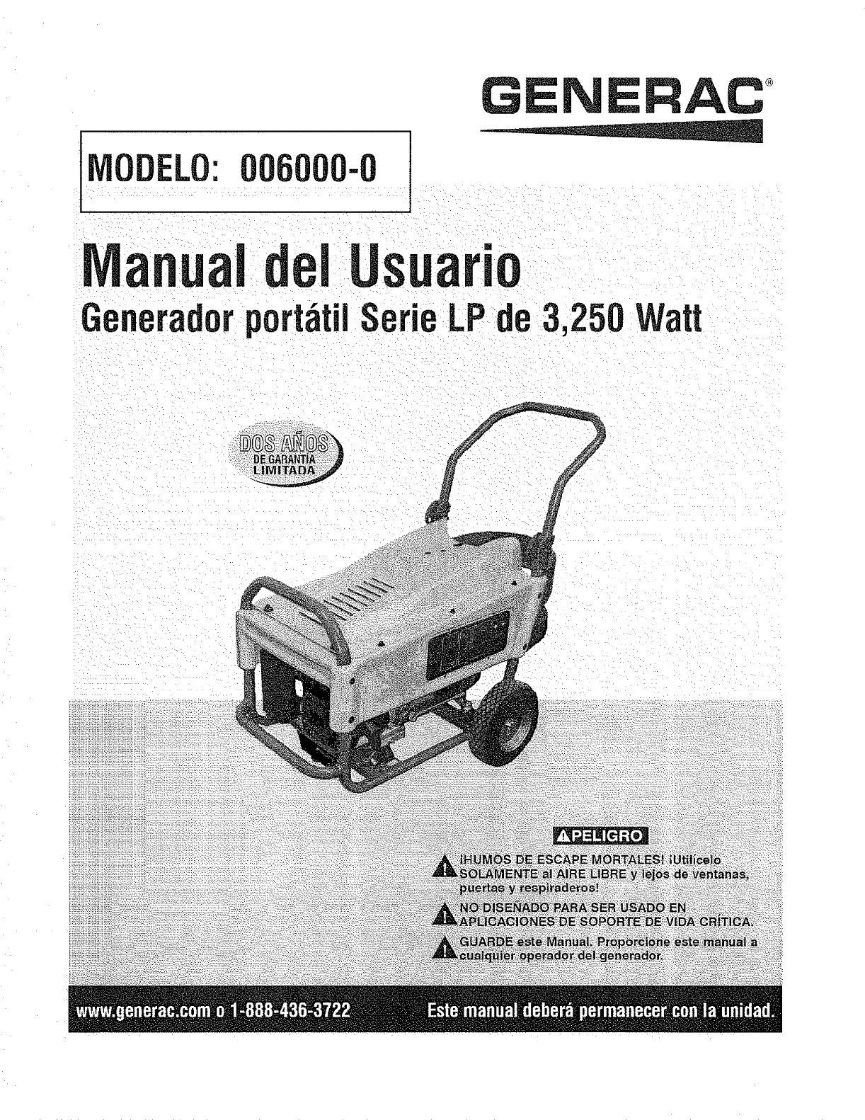
00-0
GENERAC
I d Usua "
eneradorportatilSerie_LPde3,
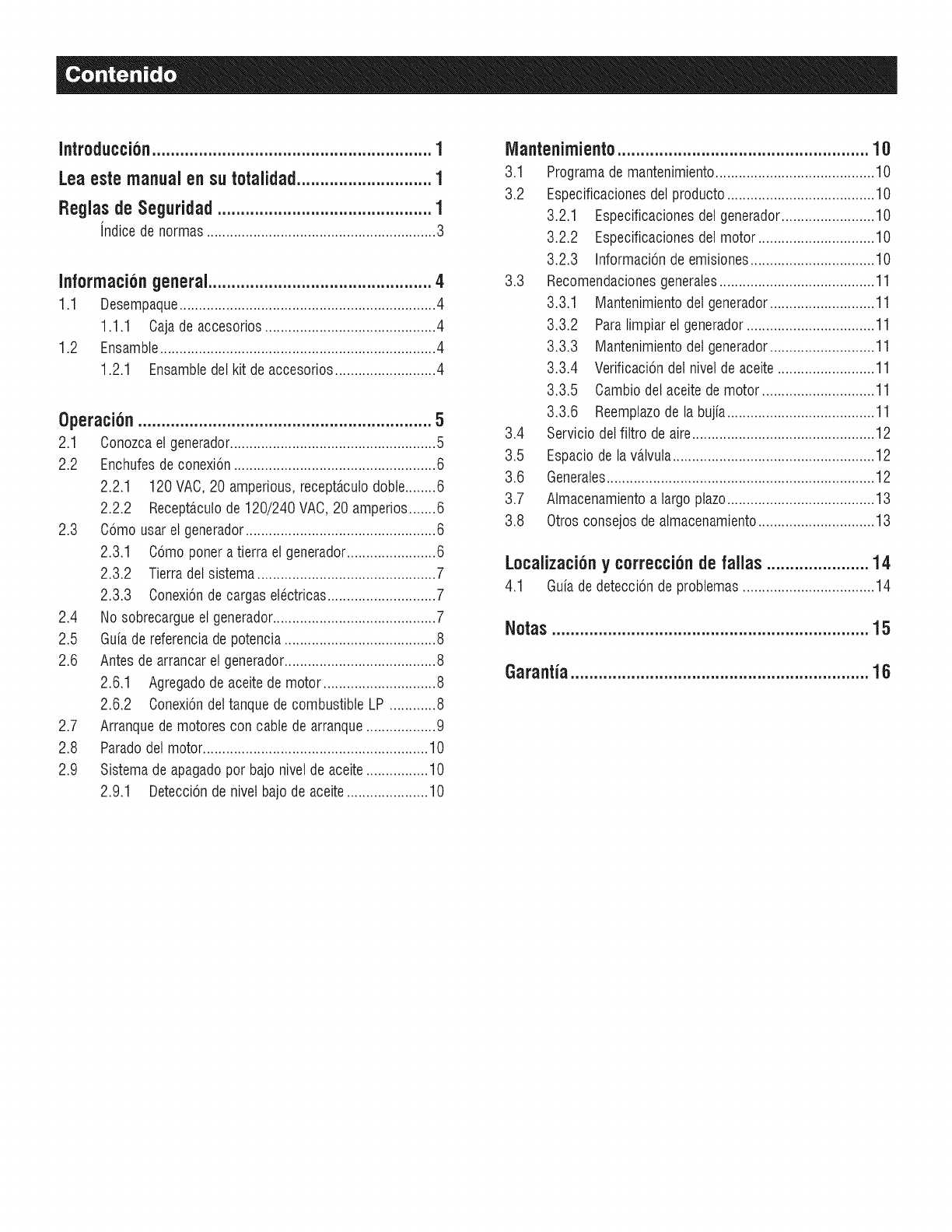
Introduccion............................................................1
Leaestemanualensu totalidad.............................1
Reglasde Seguridad ..............................................1
indice de normas...........................................................3
Informaciongeneral................................................4
1.1 Desempaque..................................................................4
1.1.1 Cajade accesorios............................................4
1.2 Ensamble.......................................................................4
1.2.1 Ensambledel kit deaccesorios..........................4
Operation ...............................................................5
2.1 Conozcael generador.....................................................5
2.2 Enchufesde conexion....................................................6
2.2.1 120 VAC,20 amperious, receptaculodoble........6
2.2.2 Recept_,culode 120/240 VAC,20 amperios.......6
2.3 Como usar et generador.................................................6
2.3.1 Comoponera tierra et generador.......................6
2.3.2 Tierra del sistema..............................................7
2.3.3 Conexionde cargas etectricas............................7
2.4 No sobrecargueet generador..........................................7
2.5 Guiade referenciade potencia.......................................8
2.6 Antes de arrancaret generador.......................................8
2.6.1 Agregadode aceitede motor .............................8
2.6.2 Conexiondel tanquede combustible LP ............8
2.7 Arranquede motores con cable de arranque..................9
2.8 Paradodet motor..........................................................10
2.9 Sistema de apagadopor bajo nivel de aceite................10
2.9.1 Deteccionde nivetbajo de aceite.....................10
iVlantenimiento......................................................10
3.1 Programade mantenimiento......................................... 10
3.2 Especificacionesdel producto......................................10
3.2.1 Especificacionesdelgenerador........................10
3.2.2 Especificacionesdelmotor ..............................10
3.2.3 Informacionde emisiones................................10
3.3 Recomendacionesgenerales........................................11
3.3.1 Mantenimientodet generador........................... 11
3.3.2 Paralimpiar el generador.................................11
3.3.3 Mantenimientodet generador........................... 11
3.3.4 Verificaciondet nivel de aceite......................... 11
3.3.5 Cambiodel aceitede motor ............................. 11
3.3.6 Reemplazode la bujia......................................11
3.4 Servicio delfiltro de aire............................................... 12
3.5 Espaciode la vatvula....................................................12
3.6 Generales.....................................................................12
3.7 Almacenamientoa largoplazo......................................13
3.8 Otrosconsejos dealmacenamiento..............................13
Localizationy correctionde fallas ......................14
4.1 Guiade deteccionde problemas..................................14
Notas....................................................................15
Garantia................................................................16
INTRODUCCi6H
Gracias per comprar este generadorporta.til de Generac Power
Systems, Inc. Este modelo es un generadorcompacto, de alto
rendimiento,enfriadoper aire y accionadoper un motor que esta.
disenadopara suministrarcorrienteelectrica paraimpulsar cargas
electricasdondeno estedisponibleel serviciopt_blicoelectricoo en
lugardel serviciopublicoelectricoper un apagon.
LEAESTEMANUALENSUTOTALIDAD
Si cualquier parte de este manual no se entiende, contacte al
DistribuidorAutorizadoma.scercanoparaobtenerinformacionsobre
los procedimientosde arranque,operaciony mantenimiento.
El operadores responsabledel use apropiadoy segurodel equipo.
Recomendamosencarecidamentequeel operadorlea estemanualy
comprendaa fondotodas las instruccionesantesde usarel equipo.
Tambienrecomendamosencarecidamentedarleinstruccionesa otros
usuariossobre come arrancary operar correctamentela unidad.
Estolos preparara,encase dequenecesitenoperarelequipoenuna
emergencia.
El generadorpuedeoperarde forma segura,eficientey confiable
solamentesi se situa, operay mantienecorrectamente.Antes de
operaro darmantenimientoal generador:
*Familiaricesecon todos los codigos y regulacioneslocales,
estatalesy nacionales,y sigalasal piedela letra.
*Estudiecuidadosamentetodas las advertenciasde seguridaden
estemanualyen elproducto.
,Familiaricesecon estemanualy con launidadantesdeusarla.
El fabricante no puede anticipar cada circunstancia posible que
puedaimplicarun riesgo.Las advertenciasenestemanual,yen las
etiquetasy calcomaniasenlaunidadson,perIotanto,noexhaustivas.
Si usa un procedimiento,metodode trabajoo tecnicade operacion
queel fabricanteno recomiendeespecificamente,cercioresede que
es seguropara otros. Tambienasegt_resede que el procedimiento,
metodode trabajo o tecnica de operacionutilizadano hagaque el
generadorseainseguro.
LA INFORMACIONINCLUIDAEN EL PRESENTESE BASAEN LAS
MAQUINASEN PRODUCCIONA LA HORADE LA PUBLICACION.
GENERACSERESERVAELDERECHODEMODIFICARESTEMANUAL
ENCUALQUIERMOMENTO.
Conserveestasinstruccionesparafuturasreferencias.Si presta
estedispositivoaalguien, SiEMPREentreguetambiena la persona
estasinstrucciones.
REGLASDESEGURIDAD
Enestapublicacion,yen las etiquetasy calcomaniasene!generador,
los recuadrosde PELIGRO,ADVERTENCIA,PRECAUCIONy NOTA
se utilizanparaalertaral personaldeinstruccionesespecialessobre
una operacionen particular que pueda ser peligrosasi se realiza
incorrecta o negligentemente.Observelos cuidadosamente.Sus
definicionesson comesigue:
INDICAUNASITUACIONPELIGROSA0 ACCIONQUE,SI NOSE
EVITA,TRAERACOMORESULTADOLAMUERTE0UNDANGSERiO.
Indicaunasituacione accionpeligresaque, si no se evita,
podriaecasienarla muertee una lesiongrave.
CUiDADO
Indicaunasituacione accion peligresaque, si no se evita,
pedriaecasienaruna lesionmonete mederada.
NOTA:
Las Notas contienen informad6n adicional importante para
un pmcedimientoy se incluyendentrodel cuerpode/texto de
estemanual.
Estas advertenciasde seguridadno puedeneliminar los peligros
que indican.El sentidocomun y el estricto cumplimientocon las
instruccionesespecialesmientrasrealizala acciono el servicio son
esencialesparalaprevencionde accidentes.
Cuatro simbolos de seguridad de use frecuente acompananlos
cuadros de PELIGRO,ADVERTENCIAy PRECAUCION.El tipo de
informacionquecadaunoindicaes come sigue:
Estesimbolo se_alainformationdeseguridadimportante
que,si nose sigue,podriaponerenpeiigrola seguridad
personaly/olas propiedadesde terceros.
Estesimboioindicael riesgode posibleexplosi6n.
//_Este simboloindicael riesgode posibleincendio.
//_Este simbolo indicael riesgodeposibledescargaeiectrica.
PELIGROSGENERALES
* NUNCAopereenun a.reacerradao eninteriores,en unvehiculo,
inclusosi las puertasy ventanasesta.nabiertas.
*Per razones de seguridad, el fabricante recomienda que el
mantenimientode este equipo se realice per un Distribuidor
Autorizado.Examineel generadorregularmente,y contacte al
DistribuidorAutorizadoma.scercanoparalas piezasquenecesitan
repararseo reemplazarse.
*Soloopereel generadoren superficiesniveladasy dondeno este
expuestoa humedad,suciedad,polvo o vaporescorrosives,en
exceso.
*Mantengalas manes,pies, ropa, etc.,alejadosde las bandasde
impulsion,de los ventiladoresy de otras piezasmoviles.Nunca
quite algunaguardao blindajede los ventiladoresmientras la
unidadesta.enoperacion.
* Ciertas piezasdel generadorse calientandemasiadodurantela
operaci6n.Mantengasealejadodel generadorhastaquese haya
enfriadoparaevitarquemadurasgraves.
*NOopereelgeneradorenla Iluvia.
* No modifiquela estructuradel generadorni cambielos controles
puestoquepodriacrearunacondiciondefuncionamientoinsegura.
* Nunca arranque o pare la unidad con las cargas electricas
conectadasalostomacorrientesY conlosdispositivosconectados
ENCENDIDOS.Arranqueel motor y dejelo estabilizarseantes
de conectar las cargaselectricas.Desconectetodas las cargas
electricasantesdeapagarel generador.
• No inserte objetos a traves de las ranuras de enfriamiento de la
unidad.
• AI trabajar en este equipo, permanezca alertatodo el tiempo. Nunca
realice trabajos en el equipo cuando este cansado fisicamente o
mentalmente.
Nunca utilice el generador o ninguna de sus piezas como escalon.
Si se para sobre la unidad puede ejercer presion y romper piezas,
y esto puede generar condiciones de funcionamiento peligrosas
como fugas de gases de escape, fugas de combustible, fugas de
aceite, etc.
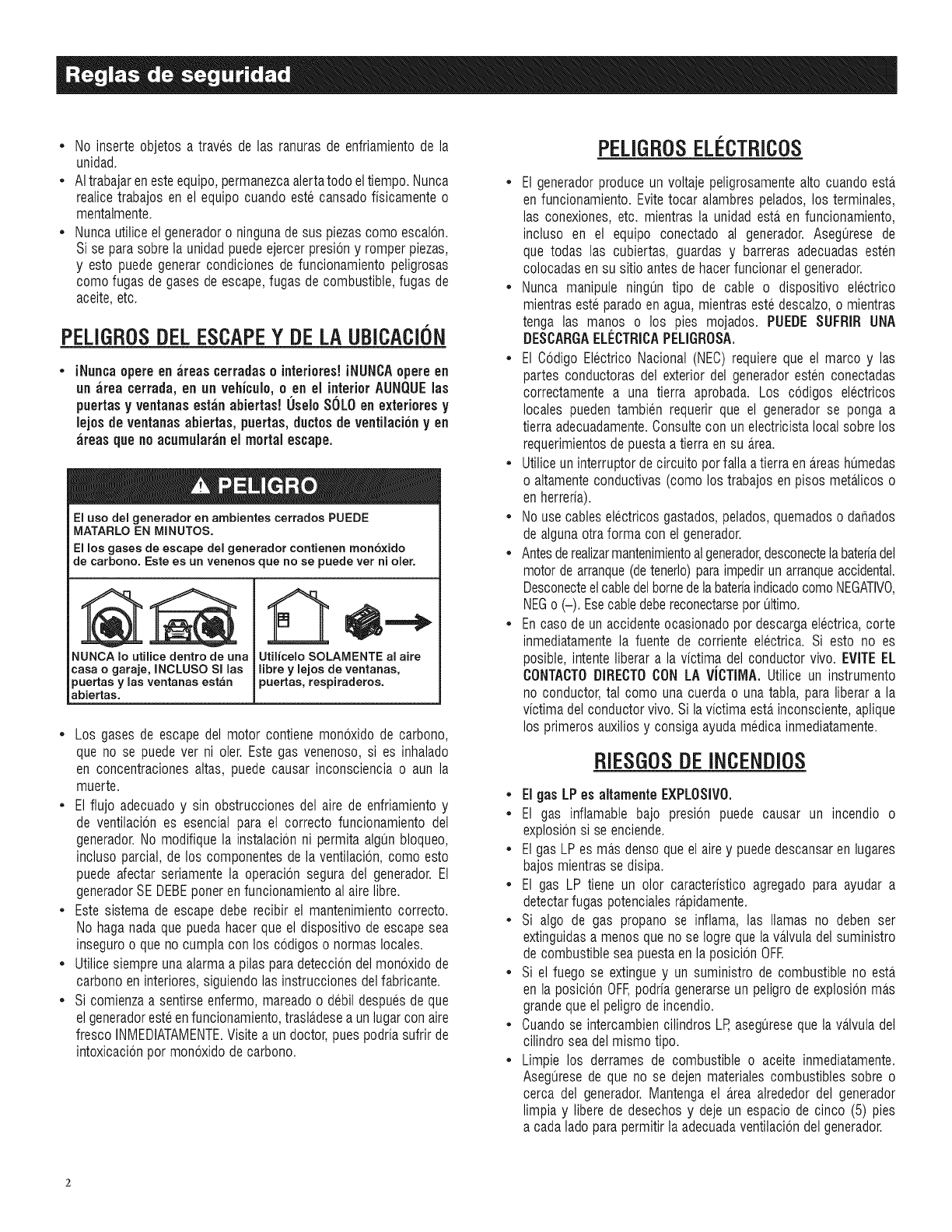
PELIGROSDELESCAPEY DELAUBICACION
• iNuncaopere enareas cerradaso interiores!iNUNCAopereen
an area terraria, en an veNculo,oen el interiorAUNQUEins
puertasy ventanasestanabiertas! 0selo SOLOen exteriores y
lejosdeventanasabiertas, puertas,ductos de ventilaci6ny en
areas queno acumularanel mortal escape.
El uso del generador en ambientes cerrados PUEDE
MATARLO EN MINUTOS.
El los gases de escape del generador contienen mono×ido
de carbono. Este es un venenos que no se puede vet ni clef.
NUNCA Io utilice dentro de urta
casa ogaraje, INCLUSO Sl las
puertas ylas ventanas estan
abiertas.
Utilicelo SOLAMENTE al aire
libre ylejos de ventanas,
puertas, respiraderos.
Los gasesde escapedel motor contienemonoxidode carbono,
que no se puedever ni oler. Estegas venenoso,si es inhalado
en concentracionesaltas, puedecausar inconscienciao aun la
muerte.
•El flujo adecuadoy sin obstruccionesdel airede enfriamientoy
de ventilaciones esencialpara el correcto funcionamientodel
generador.No modifiquela instalacionni permitaalgt_nbloqueo,
inclusoparcial,de los componentesdela ventilacion,como esto
puedeafectarseriamentela operacionseguradel generador.El
generadorSEDEBEponerenfuncionamientoal airelibre.
Estesistemade escapedeberecibir el mantenimientocorrecto.
No haganadaque puedahacer queel dispositivodeescapesea
inseguroo quenocumplacon los codigoso normaslocales.
Utilicesiempreunaalarmaapilas paradetecciondelmonoxidode
carbonoeninteriores,siguiendolas instruccionesdelfabricante.
Si comienzaa sentirseenfermo,mareadoo debildespuesde que
elgeneradoresteenfuncionamiento,trasla.deseaun lugarcon aire
fresco INMEDIATAMENTE.Visitea undoctor,puespodriasufrirde
intoxicacionpor monoxidodecarbono.
PELIGROSELI CTRICOS
• El generadorproduceun voltajepeligrosamentealto cuandoesta.
enfuncionamiento.Evitetocar alambrespelados,los terminales,
las conexiones,etc. mientrasla unidadesta.en funcionamiento,
incluso en el equipo conectado al generador.Asegt_resede
que todas las cubiertas,guardas y barreras adecuadasesten
colocadasen su sitioantesdehacerfuncionarelgenerador.
• Nunca manipule ningt_ntipo de cable o dispositivo electrico
mientrasesteparadoenagua,mientrasestedescalzo,o mientras
tenga las manos o los pies mojados. PUEDESUFRIR UNA
DESCARGAELI_CTRICAPELIGROSA.
• El Codigo ElectricoNacional(NEC)requiereque el marcoy las
partes conductorasdel exteriordel generadoresten conectadas
correctamentea una tierra aprobada.Los codigos electricos
locales puedentambien requerirque el generadorse ponga a
tierraadecuadamente.Consultecon unelectricistalocalsobrelos
requerimientosdepuestaatierra ensu a.rea.
• Utiliceun interruptordecircuitoporfalla atierraena.reashumedas
o altamenteconductivas(comolos trabajosenpisos meta.licoso
enherreria).
• No usecableselectricosgastados,pelados,quemadoso dafiados
dealgunaotraformacon el generador.
• Antesderealizarmantenimientoalgenerador,desconectelabateriadel
motorde arranque(detenerlo)paraimpedirun arranqueaccidental.
DesconecteelcabledelbornedelabateriaindicadocomoNEGATIVO,
NEGo (-). Esecabledebereconectarseporultimo.
• Encasodeun accidenteocasionadopordescargaelectrica,corte
inmediatamentela fuente de corrienteelectrica. Si esto no es
posible,intenteliberara la victima delconductorvivo. EVITEEL
CONTACTODIRECTOCONLAViCTIMA.Utilice un instrumento
no conductor,tal como una cuerdao unataN& paraliberara la
victimadelconductorvivo.Si lavictimaesta.inconsciente,aplique
los primerosauxiliosy consigaayudamedicainmediatamente.
RIESGOSDEINCENDiOS
• El gas LPes altamente EXPLOSIVO.
• El gas inflamablebajo presion puede causar un incendio o
explosionsi se enciende.
Elgas LPes ma.sdensoqueelairey puededescansaren lugares
bajosmientrasse disipa.
El gas LP tiene un olor caracteristicoagregadopara ayudar a
detectarfugaspotencialesra.pidamente.
Si algo de gas propano se inflama, las llamas no deben ser
extinguidasa menosquenose Iogrequelava.lvuladelsuministro
decombustibleseapuestaenla posicionOFR
Si el fuego se extinguey un suministrode combustibleno esta
en laposicionOFF,podriagenerarseun peligrodeexplosionmas
grandequeel peligrode incendio.
Cuandose intercambiencilindrosLP,asegt_resequela va.lvuladel
cilindroseadelmismotipo.
Limpie los derramesde combustibleo aceite inmediatamente.
Aseguresede que no se dejenmaterialescombustiblessobre o
cerca del generador.Mantengael a.reaalrededordel generador
limpiay liberede desechosy dejeun espaciode cinco (5) pies
a cadaladoparapermitirla adecuadaventilaciondelgenerador.
• No inserte objetos a traves de las ranuras de enfriamiento de la
unidad.
• Ne opere el generador si los dispositivos electricos conectados
se recaNentan, si se pierde la corriente de salida, si el motor o
el generador generan chispas o si se observan llamas o humo
mientras la unidad esta.en funcionamiento.
• Tenga un extintor cerca del generador en todo momento.
JNO/CEOENORMAS
1. Asociacion nacional de proteccion contra incendios (NFPA)70: El
CODIGOELI_CTRICONACIONAL(NEC)disponibleenwww.nfpa.org
2. Asociacion nacional de proteccion contra incendios (NFPA)5000:
CODtGODEEDIFICACIONY SEGURIDADdisponibleenwww.nfpa.org
3. El Codigo internacional de la construccion disponible en www.
iccsafe.org
4. Manual de CableadoAgricola disponible enwww.rerc.org, Consejo
de Recursos de Electricidad Rural RO. Box 309 Wilmington, OH
45177-0309
5. ASAE EP-364.2 Instalacion y mantenimiento de energia electrica
de respaldo en granjas disponible en www.asabe.org, Sociedad
AmericanadeIngenierosAgricolasy Biologicos2950 Niles Road, St.
Joseph, MI49085
Estalista no es inclusiva. Verifiquecon la Autoridadcon jurisdiccion local
(AHJ) cualesquieracodigos locales o normas que puedanser aplicables
a su jurisdiccion.
N.° DEMODELO:
N.° DESERIE:
Ubicacion de la identificacion de la unidad
ADVERTENCIADE LAPROPOSICI()N65 DECALIFORNIA
El estadode Californiaha identificadoquelos gasesde escape
del motory algunosde sus compuestospuedencausarcancer,
defectosde nacimientoy otros da_os reproductivos.
ADVERTENCIA DE LA PROPOSICI()N 65 DE CALiFORNiA
Et estado de California ha identificado que este producto contiene
Io emite sustancias quimicas que pueden causar cancer, defectos
l de nacimiento y otros da_os reproductivos.
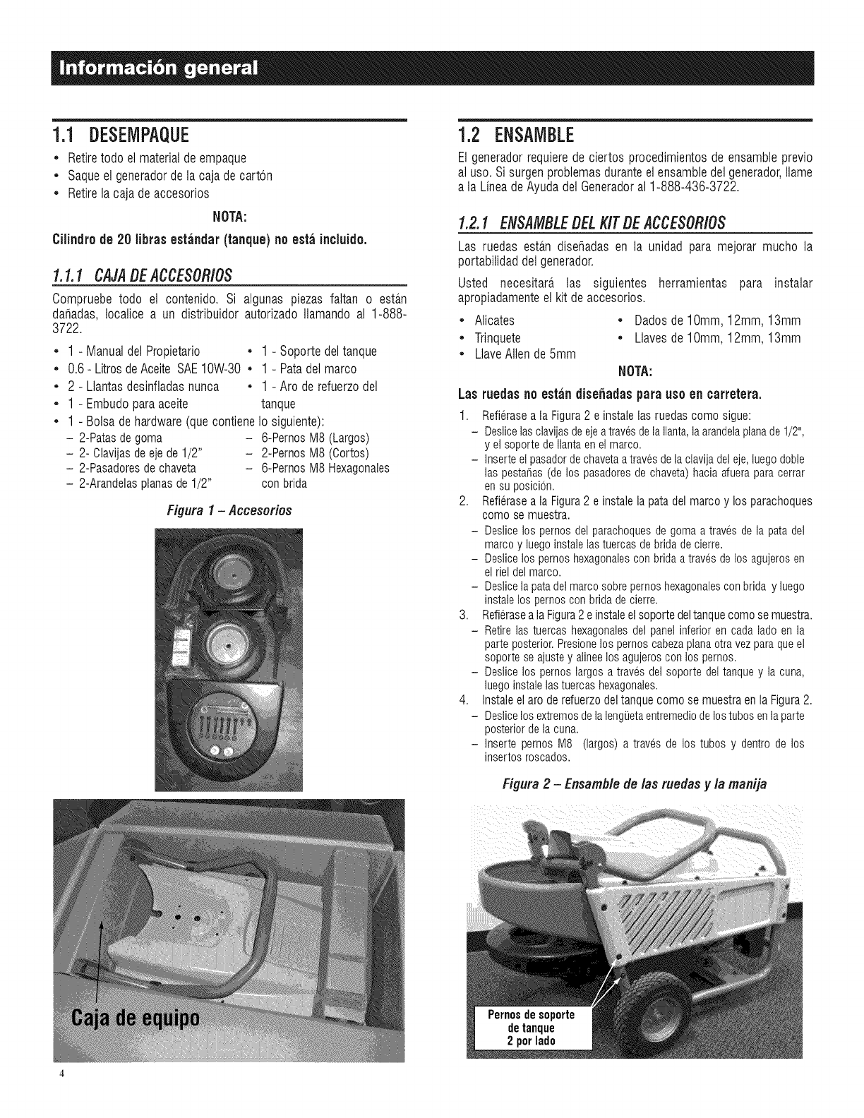
1.1 DESEMPAQUE
• Retire todo el material de empaque
•Saque el generador de la caja de cart6n
•Retire la caja de accesorios
NOTA:
Cilindrode 20 librasestandar(tanque)no estaincluido.
1.1.1 CAJADEACCESORIOS
Compruebetodo el contenido. Si algunas piezasfaltan o esta.n
dar_adas,Iocalice a un distribuidorautorizadoIlamandoal 1-888-
3722.
• 1 - ManualdelPropietario • 1 - Soportedeltanque
• 0.6- LitrosdeAceiteSAE10W-30 • 1 - Patadelmarco
•2 - Llantasdesinfladasnunca •1 - Arc de refuerzodel
• 1 - Embudoparaaceite tanque
•1 - Bolsadehardware(quecontieneIo siguiente):
- 2-Patasdegoma - 6-PernosM8 (Largos)
- 2- Olavijasdeejede1/2" - 2-PernosM8 (Cortos)
- 2-Pasadoresdechaveta - 6-PernosIV18Hexagonales
- 2-Arandelasplanasde1/2" conbrida
Figura I-Accesorios
1.2 ENSAMBLE
El generadorrequierede ciertos procedimientosde ensambleprevio
al uso.Sisurgenproblemasduranteelensambledelgenerador,Ilame
a la LineadeAyudadelGeneradoral 1-888-436-3722.
1.2.1 ENSAMBLEDELKITDEACCESORIOS
Las ruedas esta.ndisehadasen la unidadpara mejorar mucho la
portabilidaddelgenerador.
Usted necesitara, las siguientes herramientas para instalar
apropiadamenteel kit deaccesorios.
• Alicates • Dadosde10mm, 12mm,13mm
•Trinquete •Llavesde10mm, 12mm,13mm
•LlaveAllende5mm
NOTA:
Las ruedasnoest;in dise_adaspara uso en carretera.
1. Refierasea la Figura2 e instale las ruedas como sigue:
- DesiJcelasclavijasdeejeatravesde lallanta,laarandelaplanade1/2",
y el soportedellantaenelmarco.
- Inserteel pasadordechavetaatravesdela clavijadeleje,luegodoble
las pestafias(de los pasadoresde chaveta)haciaafueraparacerrar
ensu posJci6n.
2. Refierasea la Figura2 e instalela patadel marco y los parachoques
como se muestra.
- DesiJcelos pernosdel parachoquesde gomaa travesde la pata del
marcoy luegoinstaielastuercasde bridade cJerre.
- Deslicelos pernoshexagonalescon brida a travesdelos agujerosen
el riel delmarco.
- Deslicela patadel marcosobrepernoshexagonaiescon brida y luego
instaielos pernoscon bridade cierre.
3. Refieraseala Figura2 e instaleel soportedeltanquecomo se muestra.
- Retirelas tuercashexagonalesdel panel inferioren cada lado en la
parteposterior.PresJonelos pernoscabezaplanaotra vezparaqueel
soportese ajustey aiJneelosagujeroscon los pernos.
- DesiJcelos pernoslargosa traves del soporte del tanquey la cuna,
luegoinstaielastuercashexagonales.
4. Instale elaro de refuerzodel tanque como se muestraen la Figura2.
- DesiJcelos extremosdelalengiJetaentremediodelostubos enlaparte
posteriordelacuna.
- Inserte pernos M8 (largos) a travesde los tubos y dentro de los
insertosroscados.
Figura 2-Ensamble de las ruedas yla manija
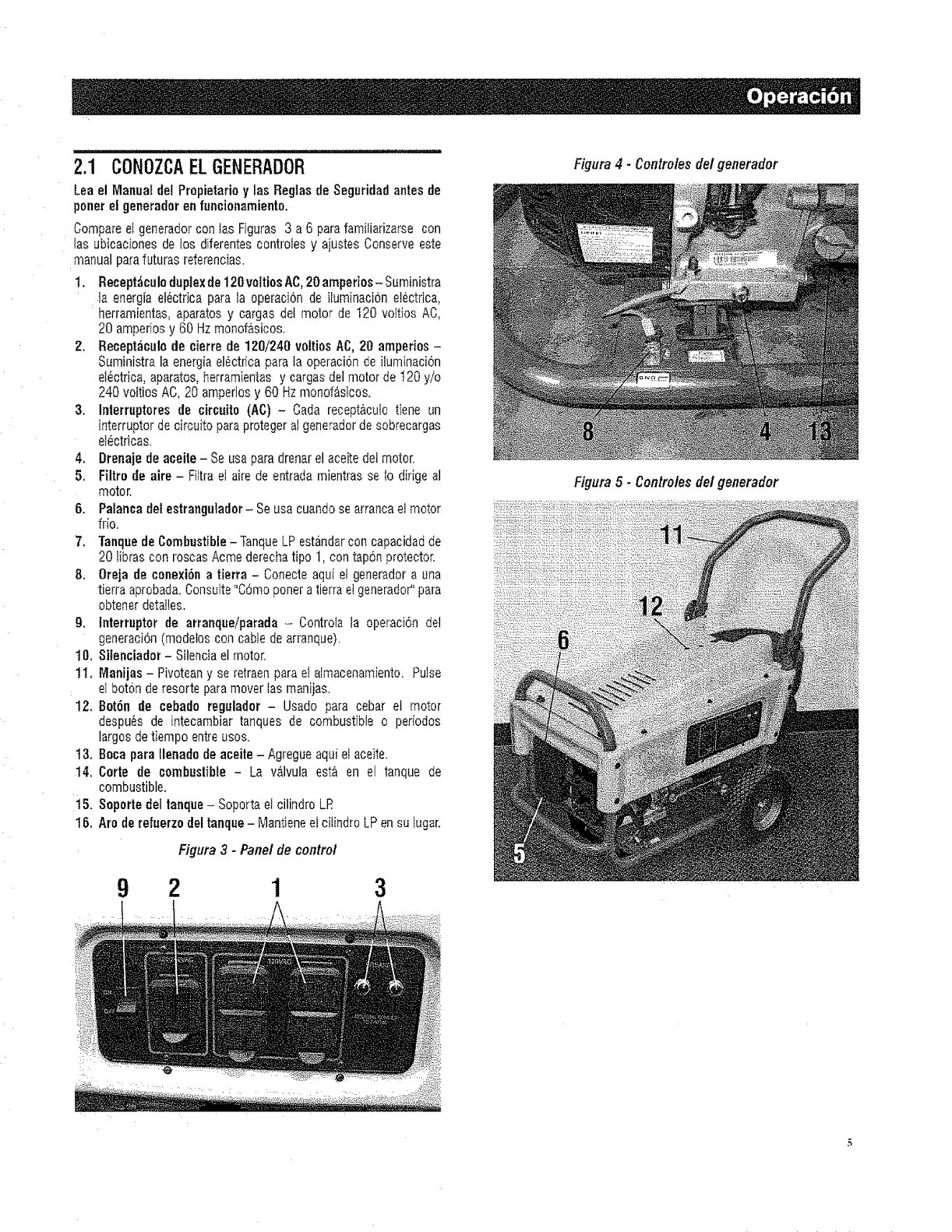
2.1 CONOZCAELGENERADOR
Leael ManualdeiPropietariay losRegiasde Seguridadantesde
ponerel generadorenfuncionamiento,
Comparee[ generadorcon tas Figuras 3 a 6 parafamiliarizarse con
las ubicaciones de tos diferentescontroies y ajustes Conserveeste
manualparafuturas referencias.
t. Recept_culaduplex de 120voitiosAC,20amperios- Surninistra
]a energia el_ctrica para la operacion de iluminacion eJectrica,
herramientas,aparatos y cargas del motor de 120 vo]tios AC,
20 amperiosy 60 Hzmonof_,sicos.
2, Receptaculo de cierre de 120/240 voltios AC, 20 amperios-
Suministra la energiaelectrica para ta operaci6n de iluminaci6n
eldctfica, aparatos,herramientas y cargos del motor de 120 y/o
240 vottiosAC, 20 amperiosy 60 Hz monof_sicos.
3. Interruptoresde circuito (AC) -Coda recept&cuiotiene un
interruptor de circuito para protegeraI generadorde sobrecargas
eI_ctricas.
4, Drenaje de aceite- Se usa paradrenarel aceitedel motor,
5. Filtrode aire - Filtra el aire de entradamientras selo dirige al
motor.
'6. Palancadot estrangulador- Seusa cuandose arrancael motor
frio,
7. Tanquede Combustible -Tanque LP estandarcon capacidadde
20 libras con roscas Acmederecha tipo 1, con taponprotector.
8, Oreja de conexibna tierra - Conecte aqui et generadora una
tierra aprobada.Consulte"C6moponera tierra elgenerado¢'para
obtenerdetalies.
9. Interruptor de arranqueiparada -Controla ta operaci6n de!
generaci6n(modeloscon cable dearranque).
t0, Silenciador - Silenciael motor,
11. Manijas- Pivoteany se retraenpara ei aimacenamiento. Pulse
el baton de resorte paramover ias manijas.
12, Bot6n de cebado regulador -Usado para cebar el motor
despu6s de intecambiar tanques de combustible o periodos
largosde tiempo entreusos.
t3. Boca para Ilenado de aceite - Agregueaqui e] aceite.
t4. Carte de combustible- La v_,lvula esta en el tanque de
combustible.
15. Soporte del tanq.e - Soportael cilindro LR
16. Are derefuerzo deltanque - Mant[eneel citindro LPen su iugar,
Figaro3-Panelde control
921 3
::i:!!i:!i!i!ii!:ii:;iiii
Figaro4 -Conlrolesdel generador
Figura5- Controlesdelgenerador
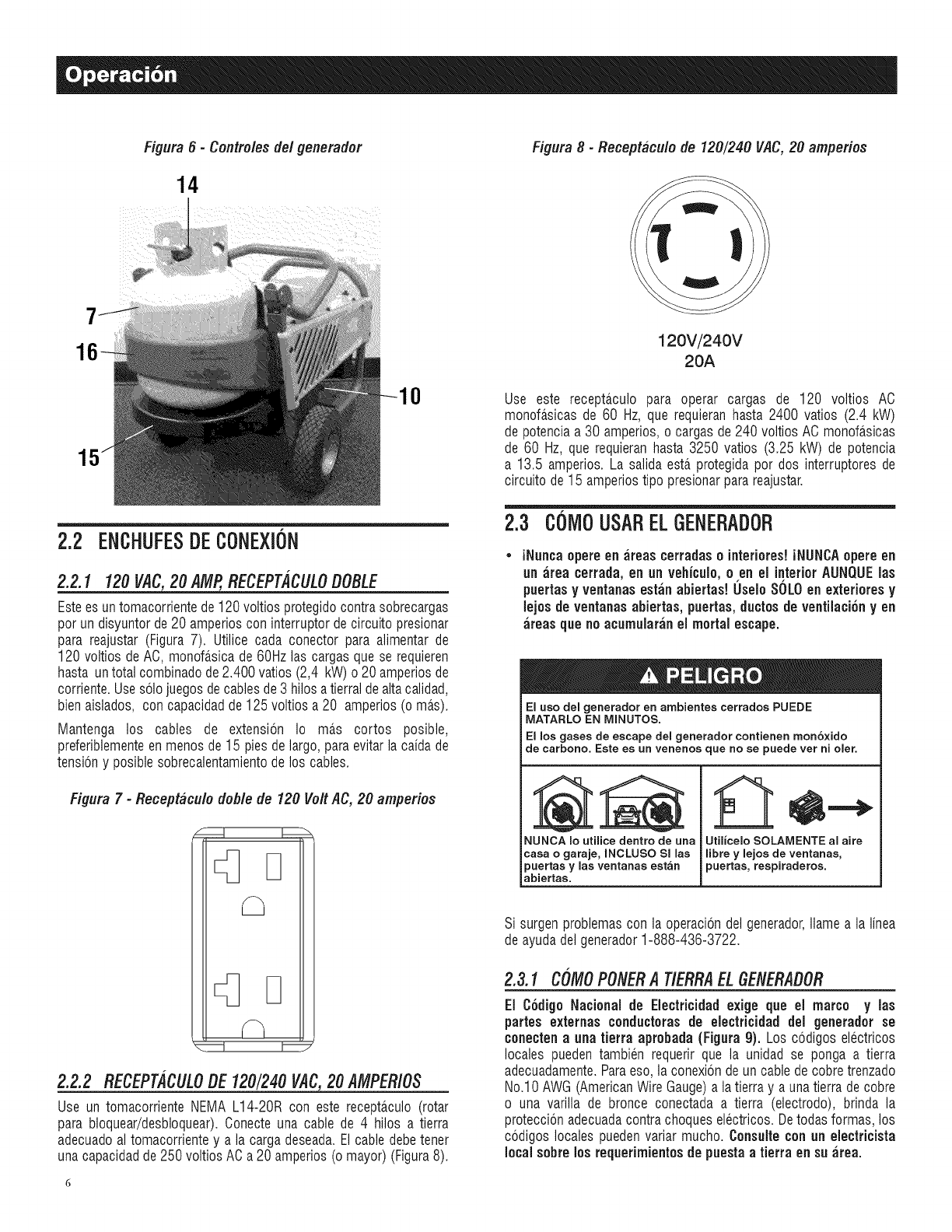
Figura6- Controlesde/generador
14
0
2.2 ENCHUFESDECONEXiON
2.2.1 120VAC,20 AMP,RECEPTACULOOOBLE
Esteesuntomacorrientede120voltiosprotegidocontrasobrecargas
pot un disyuntorde20 amperioscon interruptordecircuitopresionar
para reajustar(Figura7). Utilice cada conector para alimentarde
120 voltios deAC,monofasicade 60Hzlas cargasquese requieren
hasta untotalcombinadode2.400vatios(2,4 kW)o 20 amperiosde
corriente.Uses61ojuegosdecablesde3 hilosatierraldealtacalidad,
bienaislados, con capacidadde125voltiosa 20 amperios(omas).
Mantenga los cables de extension Io mas cortos posible,
preferiblementeenmenosde 15 piesde largo,paraevitarla caidade
tensbn y posiblesobrecalentamientode los cables.
Figura 7 -Receptaculo doble de 120 VoltAC, 20 amperios
D
2.2.2 RECEPTACULOOE120/240 VAC,20 AMPERIOS
Use un tomacorrienteNEMAL14-20R con este receptaculo(rotar
para bloquear/desbloquear).Conecteuna cable de 4 hilos a tierra
adecuadoal tomacorrientey a la cargadeseada.Elcabledebetener
unacapacidadde250voltiosACa 20amperios(omayor)(Figura8).
Figura 8 -Receptaculo de 120/240 VAC,20 ampefios
120V/24OV
20A
Use este receptaculo para operar cargas de 120 voltios AO
monofasicasde 60 Hz, que requieranhasta 2400 vatios (2.4 kW)
de potenciaa 30 amperios,o cargasde240 voltiosAC monofasicas
de 60 Hz, que requieranhasta 3250 vatios (3.25 kW) de potencia
a 13.5 amperios.La salidaesta protegidapot dos interruptoresde
circuitode 15 amperiostipo presionarparareajustar.
2.3 COM0USARELGENERADOR
iNuncaopereen areas cerradaso interiores!iNUNCAopereen
an area cerrada,en an vehiculo,o en el interiorAUNQUElas
puertasyventanasestanabiertas! UseloSOLOen extefioresy
lejosdeventanasabiertas, puertas,ductosde ventilaci6ny en
areas quenoacumuiaranel mortal escape.
El uso del generador en ambientes cerrados PUEDE
MATARLO EN MINUTOS.
El los gases de escape del generador contienen monoxido
de carbono. Este es un venenos que no se puede ver ni oler.
NUNCA Io utilice dentro de una
casa o garaje, INCLUSO SI las
puertas ylas ventanas estan
abiertas.
Utilicelo SOLAMENTE al aire
iibre ylejos de ventanas,
puertas, reepiraderos.
Si surgenproblemascon ]a operaci6nde] generador,]lamea]a]inea
deayudade]generador1-888-436-3722.
2.3.1 COMOPONERA TIERRAEL6ENERADOR
El Codigo Nacional de Eiectricidad exige que el marco y las
partes externas conductorasde electricidad del generadorse
conectenaunatierra aprobada(Figura 9). Los codigoselectricos
localespuedentambien requerirque la unidad se ponga a tierra
adecuadamente.Paraeso,]aconexbndeuncabledecobretrenzado
No.10AWG(AmericanWireGauge)a]atierray a unatierrade cobre
o una varilla de bronce conectada a tierra (electrodo), brinda la
proteccionadecuadacontrachoqueselectricos.Detodasformas,los
codigoslocalespuedenvariar mucho.Consulteconan electficista
localsobre losrequerimientosde puestaa tierra en su area.
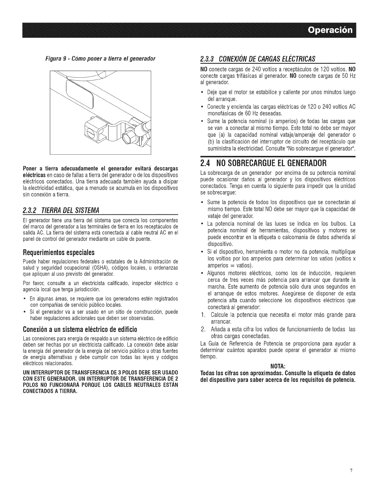
Fifura 9-C6moponer atierra el #enerador
Porter a tierra adecuadamenteel generadorevitara descargas
eiectricasencasedefallasatierradelgeneradoro delos dispositivos
electricosconectados.Unatierra adecuadatambienayudaa disipar
la electricidadesta.tica,queamenudose acumulaenlos dispositivos
sin conexionatierra.
2.3.2 T/ERRAgEL $/$TEMA
El generadortiene una tierra del sistema que conecta los componentes
del marco del generadora lasterminales de tierra en los recepta.culosde
salidaAC. Latierra del sistema esta_conectadaal cable neutralAC en el
panel de control del generadormedianteun cable de puente.
Bequerimientosespeciales
Puedehaberregulacionesfederaleso estatalesdela Administracionde
saludy seguridadocupacional(OSHA),codigoslocales,u ordenanzas
queapliquenaluseprevistodelgenerador.
Per favor, consultea un electricistacalificado,inspectorelectricoo
agencialocalquetengajurisdiccion.
= Enalgunasa_reas,se requierequelos generadoresestenregistrados
concompahiasdeserviciopublicolocales.
*Si el generadorva a ser usadoen un sitio de construcci6n,puede
haberregulacionesadicionalesquedebenserobservadas.
Conexiona unsistemaelectricodeedificio
Lasconexionesparaenergiaderespaldoaunsistemaelectricodeedificio
debenserhechasperun electricistacalificado.Laconexiondebeaislar
laenergiadelgeneradordela energiadelserviciopublicouotrasfuentes
de energiaalternativasy debecumplircon todas las leyesy codigos
electricosrelacionados.
UH INTERRUPTERDETRAHSFEREHCIADE3 POLOSDEBESERUSADO
CONESTEGEHERADOR.UH IHTERRUPTORDETRAHSFEREHCIADE2
POLOS NO FUNCIONABA PORQUE LOS CABLES NEUTRALES ESTAN
CONECTADOS A TIERRA.
2.3.3 CONEX/ONDECARGASE!._CTR/CA$
NO conecte cargas de 240 voltios a recepta.culos de 120 voltios. NO
conecte cargas trifa.sicas al generador. NO conecte cargas de 50 Hz
al generador.
• Deje que el motor se estabilice y caNenteper unos minutes luego
del arranque.
• Conecte y encienda las cargas electricas de 120 o 240 voltios AC
monofa.sicas de 60 Hz deseadas.
• Sume la potencia nominal (o amperios) de todas las cargas que
se van a conectar al mismo tiempo. Estetotal no debe ser mayor
que (a) la capacidad nominal vataje/amperaje del generador o
(b) la clasificacion del interrupter de circuito del recepta.culo que
suministra la electricidad. Consulte "No sobrecargue el generador".
2.4 NO SOBRECARGUEELGENERADOR
La sobrecargade un generadorper encimade su potencianominal
puedeocasionardafios al generadory los dispositivoselectricos
conectados.Tengaen cuentaIo siguienteparaimpedirquela unidad
se sobrecargue:
= Sumela potenciade todos los dispositivosquese conectara.nal
mismotiempo.EstetotalNOdebeser mayorquela capacidadde
vatajedelgenerador.
* La potencianominal de las luces se indica en los bulbos. La
potencia nominal de herramientas,dispositivos y motores se
puedeencontrarenla etiquetao calcomaniadedatesadheridaal
dispositivo.
= Si el dispositivo,herramientao motorno da potencia,multiplique
los voltios per los amperiosparadeterminarlos vatios (voltiosx
amperios= vatios).
= AIgunosmotores electricos, come los de induccion, requieren
cerca de tres veces ma.spotenciaparaarrancarque durantela
marcha.Esteaumentode potenciasolo dura unos segundosen
el arranquede estos motores.Asegt_resede disponer de esta
potenciaalta cuandoseleccionelos dispositivoselectricosque
conectara,al generador:
1. Catcule la potencia que necesita et motor mas grande para
arrancar.
2. Ahadaa esta cifra los vatios de funcionamientodetodas las
otras cargasconectadas.
La Guia de Referenciade Potenciase proporcionapara ayudar a
determinarcua.ntosaparatospuede operarel generadoral mismo
tiempo.
NOTA:
Todaslas cifrassen aproximadas.Consultela etiqueta de dates
del dispositive parasaberacerca de losrequisitesde potencia.
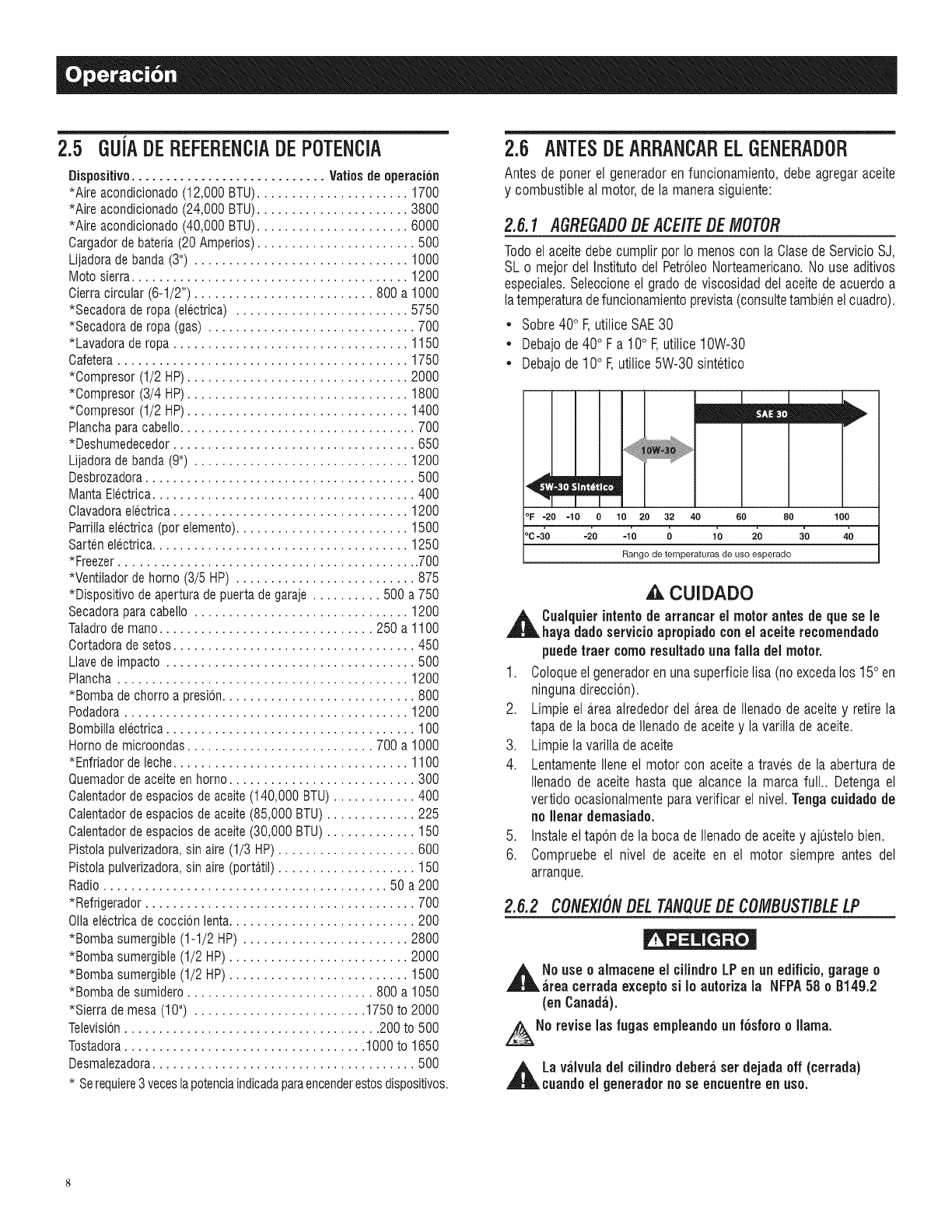
2.5 GUiADEREFERENCiADEPOTENCiA
Dispositivo ............................ Vatios de operation
*Aire acondicionado (12,000 BTU)...................... 1700
*Aire acondicionado (24,000 BTU)...................... 3800
*Aire acondicionado (40,000 BTU)...................... 6000
0argador debatefia (20 Amperios)....................... 500
Lijadoradebanda (3") ............................... 1000
Mote sierra........................................ 1200
0ierra circular (6-1/2") .......................... 800 a 1000
*Secadorade ropa (eleetrica) ......................... 5750
*Secadorade ropa (gas) .............................. 700
*Lavadorade ropa .................................. 1150
0afetera .......................................... 1750
*Compresor (1/2 HP)................................ 2000
*Compresor (3/4 HP)................................ 1800
*Compresor (1/2 HP)................................ 1400
Planchaparacabello.................................. 700
*Deshumedecedor................................... 650
Lijadora debanda (9") ............................... 1200
Desbrozadora....................................... 500
Manta Electrica...................................... 400
Clavadoraelectrica .................................. 1200
Parrillaelectrica (per elemento)......................... 1500
Sarten electrica..................................... 1250
*Freezer ............................................ 700
*Ventiladorde homo (3/5 HP) .......................... 875
*Dispositivo deapertura de puerta degaraje .......... 500 a 750
Secadoraparacabello ............................... 1200
Taladrode mane............................... 250 a 1100
Cortadora desetos................................... 450
Llavede impacto .................................... 500
Plancha .......................................... 1200
*Bomba de chorro a presion............................ 800
Podadora ......................................... 1200
Bombilla electrica .................................... 100
Hornode microondas........................... 700 a 1000
*Enfriador deleche.................................. 1100
Quemadorde aceiteen horno........................... 300
Calentadorde espacios de aceite(140,000 BTU) ............ 400
Calentadorde espacios de aceite(85,000 BTU) ............. 225
Calentadorde espacios de aceite(30,000 BTU) ............. 150
Pistolapulverizadora,sin aire (1/3 HP) .................... 600
Pistolapulverizadora,sin aire (porta.til).................... 150
Radio......................................... 50 a 200
*Refrigerador ....................................... 700
Oilaelectricade coccbn ienta........................... 200
*Bomba sumergible (1-1/2 HP) ........................ 2800
*Bomba sumergible (1/2 HP) .......................... 2000
*Bomba sumergible (1/2 HP) .......................... 1500
*Bomba de sumidero........................... 800 a 1050
*Sierra de mesa (10") ......................... 1750 to 2000
Televisbn ..................................... 200 to 500
Tostadora................................... 1000 to 1650
Desmalezadora...................................... 500
* Serequiere3 veceslapotenciaindicadaparaencenderestosdispositivos.
2.6 ANTESDEARRANCARELGENERADOR
Antesde ponerel generadorenfuncionamiento,debeagregaraceite
y combustiblea]motor,dela manerasiguiente:
2.6.1 AGREGADODEACE/TEDEMOTOR
TodoelaceitedebecumplirperIo menoscon laClasede ServicioSJ,
SLo mejorde] Institutedel PetroleoNorteamericano.No use aditivos
especiales.Seleccioneel gradedeviscosidadde]aceitedeacuerdoa
iatemperaturadefuncionamientoprevista(consultetambienelcuadro).
• Sobre40° F,utiliceSAE30
• Debajode40° F a 10° F,utilice10W-30
• Uebajode10° F,utilice5W-30 sintetico
°F -20 -10 010 20 32 40 60 80
_c/o -2'0 -1'o o 1'o 2'o
Range de temperaturas de use esperado
CUIDADO
,_ Cualquierintentode arrancar el motor antesde quesele
haya dadeservicioapropiadoconel aceiterecemendado
puedetraer comeresultadoannfalla del motor.
1. Coloqueelgeneradorenunasuperficielisa (noexcedalos 15° en
ningunadireccion).
2. Limpieel a.reaalrededordel a.reade Ilenadodeaceitey retirela
tapadela bocade Ilenadodeaceitey lavarilladeaceite.
3. Limpielavarilladeaceite
4. LentamenteIleneel motorcon aceitea travesde la aberturade
ilenadode aceitehasta que alcance]a marcafull.. Detengael
vertidoocasionalmenteparaverificarel nive].Tongacuidadode
no Henardemasiade.
5. Instaleeltaponde laboca deIlenadode aceitey ajQstelobien.
6. Compruebeel nive] de aceite en el motor siempreantes de]
arranque.
2.6.2 CONEXIONDELTANQUEDECOMBUSTIBLELP
,_No use ealmaceneel cilindroLPenan edificio,garagee
;ironcerradaexceptosi Io auterizala NFPA58 o B14g.2
(on Canada).
No reviseInsfugasempleandoan fosforo o llama.
,_La valvuladel cUindrodeberaset dejadaoff (terraria)
cuandoel generadorno se encuentreenuse.
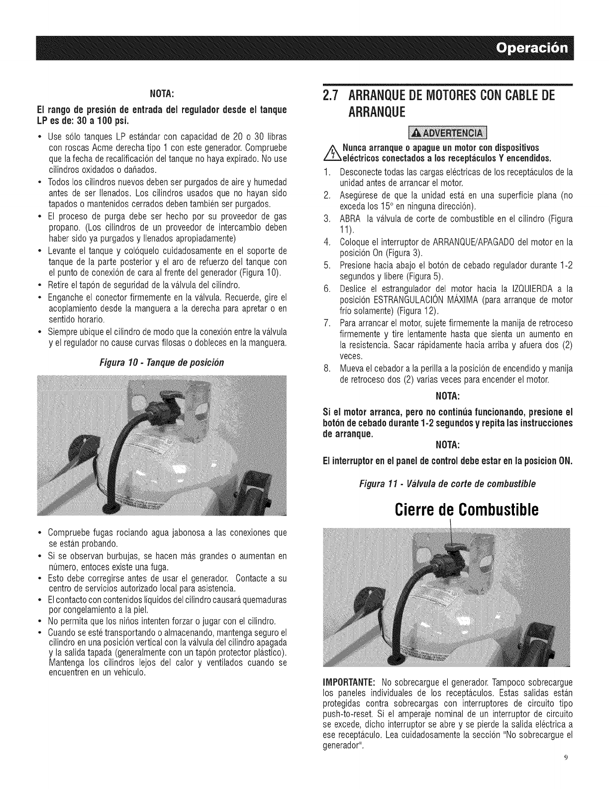
NOTA:
El tango de presionde entrada del regulador desde el tanque
LP es de: 30 a 100 psi.
• Use solo tanques LP esta.ndarcon capacidad de 20 o 30 libras
con roscas Acme derecha tipo 1 con este generador. Compruebe
que lafecha de recalificaci6n del tanque no haya expirado. No use
cilindros oxidados o dahados.
• Todos los cilindros nuevos deben set purgados de aire y humedad
antes de ser Ilenados. Los cilindros usados que no hayan sido
tapados o mantenidos cerrados deben tambien ser purgados.
El proceso de purga debe ser hecho pot su proveedor de gas
propano. (Los cilindros de un proveedor de intercambio deben
haber sido ya purgados y Ilenados apropiadamente)
Levante el tanque y coloquelo cuidadosamente en el soporte de
tanque de la parte posterior y el arc de refuerzo del tanque con
el punto de conexion de cara al frente del generador (Figura 10).
Retire el tapon de seguridad de la va.lvuladel cilindro.
Enganche el conector firmemente en la va.lvula. Recuerde, gire el
acoplamiento desde la manguera a la derecha para apretar o en
sentido horario.
Siempre ubique el cilindro de modo que la conexion entre la va.lvula
y el regulador no cause curvas filosas o dobleces en la manguera.
figura 10 - Tanquede posicion
Compruebefugas rociandoaguajabonosaalas conexionesque
se esta.nprobando.
• Si se observanburbujas,se hacenma.sgrandeso aumentanen
numero,entocesexisteunafuga.
, Estodebecorregirseantesde usar el generador.Contactea su
centrodeserviciosautorizadolocalparaasistencia.
, Elcontactoconcontenidosliquidosdelcilindrocausara,quemaduras
pot congelamientoa lapiel.
, No permitaquelos nihosintentenforzaro jugarcon el cilindro.
• Cuandoseestetransportandoo almacenando,mantengaseguroel
cilindroenunaposicionverticalcon lava.lvuladelcilindroapagada
y la salidatapada(generalmentecon untaponprotectorpla.stico).
Mantengalos cilindros lejos del calory ventiladoscuando se
encuentrenen unvehiculo.
2.7 ARRANQUEDEIV]OTORESCONCABLEDE
ARRANQUE
i_Nunca atranque oapagueunmotorcondispositivos
electdcosconectadosa los receptaculosY encendidos.
1. Desconectetodaslas cargaselectricasdelos recepta.culosdela
unidadantesdearrancarelmotor.
2. Asegt_resede que la unidadesta.en una superficie plana(no
excedalos 15° en ningunadireccion).
3. ABRA la va.lvulade corte de combustibleen el cilindro (Figura
11).
4. Coloqueel interruptordeARRANQUE/APAGADOdelmotoren la
posicionOn(Figura3).
5. Presionehacia abajoel boton decebadoreguladordurante1-2
segundosy libere(Figura5).
6. Deslice el estranguladordel motor hacia la IZQUIERDAa la
posicionESTRANGULACIONMAXIMA(paraarranquede motor
frio solamente)(Figura12).
7. Paraarrancarel motor,sujetefirmementela manijaderetroceso
firmementey tire lentamentehasta que sientaun aumentoen
la resistencia.Sacarra.pidamentehacia arribay afuerados (2)
veces.
8. Muevael cebadora laperillaa laposiciondeencendidoy manija
deretrocesodos (2) variasvecesparaencenderelmotor.
NOTA:
Si el motorarranca,pero nocontinuafuncionando, presioneel
boronde cebadodurante 1-2 segundosy repita lasinstrucciones
de arranque. NOTA:
Elinterruptoren el panelde controldebeestaren la posicionON.
Figura 11 - Valvula de corte de combustible
CierredeCombustible
IMPORTANTE:No sobrecargueel generador.Tampocosobrecargue
los paneles individualesde los recepta.culos.Estas salidas esta.n
protegidascontra sobrecargascon interruptores de circuito tipo
push-to-reset.Si el amperajenominalde un interruptorde circuito
se excede,dicho interruptorse abrey se pierdela salidaelectricaa
ese recepta.culo.Leacuidadosamentela seccion"No sobrecargueel
generador".
9
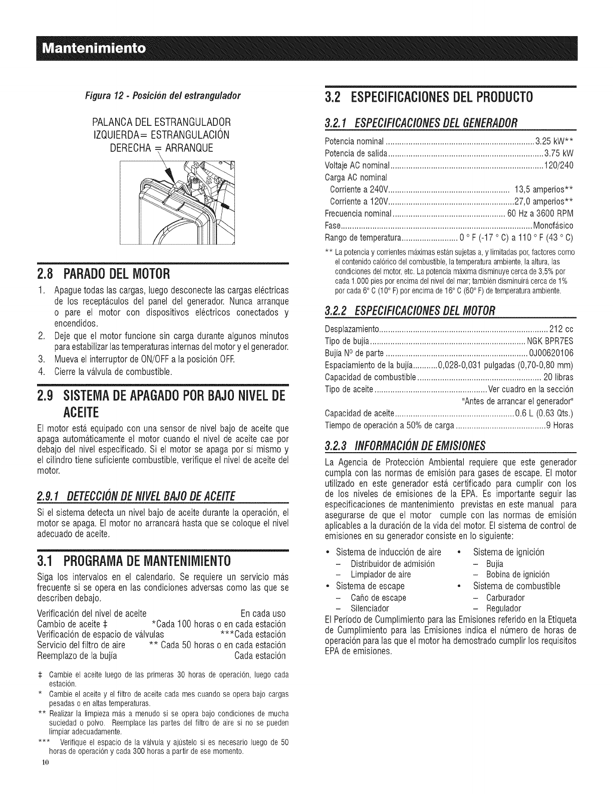
Figu_ 12-Pos_nde/estrangu_dor
PALANCADEL ESTRANGULADOR
IZQUIERDA= ESTRANGULACION
DEREOHA ARRANQUE
2.8
1.
.
3.
4.
PARADODELMOTOR
Apaguetodaslas cargas,luegodesconectelas cargaselectricas
de los recepta.culosdel panel del generador.Nuncaarranque
o pare el motor con dispositivos electricos conectadosy
encendidos.
Dejeque el motorfuncionesin carga durantealgunosminutos
paraestabilizarlastemperaturasinternasdelmotory elgenerador.
Muevaelinterruptorde ON/OFFa laposicionOFR
Cierrelava.lvuladecombustible.
2.9 SiSTEMADEAPAGADOPORBAJONIVELDE
ACEITE
El motor estaequipadocon una sensorde nivelbajo de aceiteque
apagaautomaticamenteel motor cuandoel nivel de aceitecae pot
debajodel nivel especificado.Si el motor se apagapor si mismoy
el cilindrotiene suficientecombustible,verifiqueel niveldeaceitedel
motor.
2.9.1 DETECC/ONDEN/VELBAJODEACE/TE
Si el sistemadetectaun nivel bajode aceitedurantela operacion,el
motorse apaga.Elmotorno arrancarahastaquese coloqueel nivel
adecuadodeaceite.
3.1 PROGRAMADEMANTENIMIENTO
Siga los intervalos en el calendario.Se requiereun servicio ma.s
frecuentesi se operaen las condicionesadversascomo las que se
describendebajo.
Verificaciondel niveldeaceite Encadauso
Cambiode aceite$ *Cada100horaso en cadaestacion
Verificacionde espaciodeva.lvulas ***Cada estacion
Serviciodelfiltro deaire ** Cada50 horaso en cadaestacion
Reemplazode labujia Cadaestacion
:i: Cambie el aceite luego de las primeras 30 horas de operacion, luego carla
estacion.
* Cambie el aceite y el filtro de aceite cada mes cuando se opera bajo cargas
pesadas o en altas temperaturas.
** Realizar la limpieza mas a menudo si se opera bajo condiciones de mucha
suciedad o polvo. Reemplacelas partes del filtro de aire si no se pueden
limpiar adecuadamente.
*** Verifique el espacio de la valvula y ajustelo si es necesario luego de 50
horas de operacion y cada300 horas a partir de esemomento.
1o
3.2 ESPECIFICACIONESDELPRODUCTO
3.2.1 ESPECiFICACiONESDEL6ENERADOR
Potencianominal.................................................................. 3.25 kW**
Potenciadesalida..................................................................... 3.75 kW
VoltajeACnominal.................................................................... 120/240
OargaAO nominal
Oorrientea 240V...................................................... 13,5 amperios**
Oorrientea 120V........................................................ 27,0 amperios**
Frecuencianominal.................................................. 60 Hz a 3600 RPM
Fase..................................................................................... Monofa_sico
Rangode temperatura......................... 0 ° F (-17 ° O)a 110 ° F (43 ° O)
** Lapotenciay corrientesmaximasestansujetasa, y limitadaspor,factorescomo
elcontenidocaloricodelcombustible,latemperaturaambiente,laaltura,las
condicionesdelmotor,etc.Lapotenciamaximadisminuyecercade3,5%por
cada1.000piesporencimadelniveldelmar;tambiendisminuiracercade1%
porcada6°C(10°F)porencimade16° C(60° F)detemperaturaambiente.
3.2.2 ESPEC/FiCAC/ONESDELMOTOR
Desplazamiento........................................................................... 212 cc
Tipo de bujia..................................................................... NGKBPR7ES
BujiaNOde parte ............................................................... 0J00620106
Espaciamientode la bujia...........0,028-0,031 pulgadas(0,70-0,80 mm)
Capacidadde combustible....................................................... 20 libras
Tipo de aceite..................................................Ver cuadro enla seccion
"Antesde arrancar el generador"
Capacidadde aceite..................................................... 0.6 L (0.63 Qts.)
Tiempo de operaciona 50% de carga........................................9 Horas
3.2.3 INFORMAC/ONDEEM/S/ONES
La Agencia de ProteccionAmbientalrequiereque este generador
cumplacon las normasde emisionparagasesde escape.El motor
utilizadoen este generadoresta.certificado para cumplir con los
de los niveles de emisionesde la EPA.Es importanteseguir las
especificacionesde mantenimientoprevistasen estemanual para
asegurarsede que el motor cumplecon las normas de emision
aplicablesa la duraciondela vidadelmotor.Elsistemadecontrolde
emisionesen su generadorconsisteen Io siguiente:
• Sistema de induccion de aire • Sistema de ignicion
- Distribuidor deadmision - Bujia
- Limpiador deaire - Bobina de ignicion
• Sistema de escape • Sistema de combustible
- Cahode escape - Carburador
- Silenciador - Regulador
ElPeriododeCumplimientoparalas Emisionesreferidoenla Etiqueta
de Cumplimientoparalas Emisionesindica el nt_merode horas de
operacionparalas queel motorhademostradocumplirlos requisitos
EPAdeemisiones.
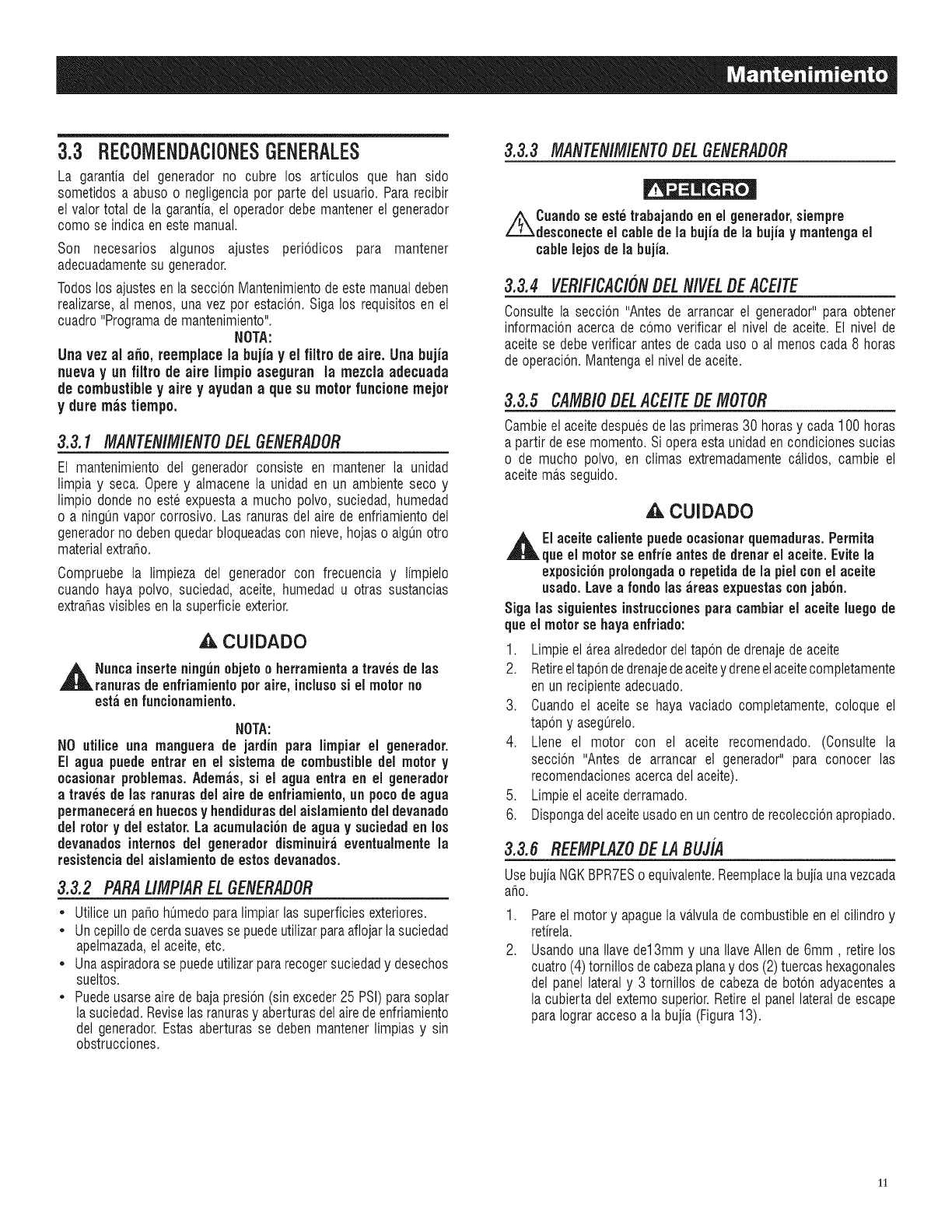
3.3 RECOIVIENDACiONESGENERALES
La garantia del generadorno cubre los articulos que han sido
sometidosa abuso o negligenciapot parte del usuario.Pararecibir
el valortotal de la garantia,el operadordebemantenerel generador
comose indicaen estemanual.
Son necesarios algunos ajustes periodicos para mantener
adecuadamentesu generador.
Todoslos ajustesen laseccionMantenimientodeestemanualdeben
realizarse,al menos,unavez pot estacion.Sigalos requisitosen el
cuadro"Programademantenimiento".
NOTA:
Una vez al a_o, reemplacela bujia yel filtro de aire. Una bujia
nuevay un filtro de aire limpio aseguran la mezcla adecuada
de combustibley aire y ayudana que su motorfuncione mejor
y dure mas tiempo.
3.3.1 MANTEN/M/EtVTODELGEtVERADOR
El mantenimientodel generadorconsiste en mantenerla unidad
limpia y seca. Operey almacenela unidaden un ambientesecoy
limpio dondeno esteexpuestaa mucho polvo,suciedad,humedad
o a ningt_nvaporcorrosivo.Las ranurasdel airede enfriamientodel
generadornodebenquedarbloqueadascon nieve,hojas o algunotro
materialextraho.
Compruebela limpieza del generadorcon frecuencia y limpielo
cuando haya polvo, suciedad,aceite,humedadu otras sustancias
extrahasvisiblesen lasuperficieexterior.
,_ CUIDADO
,A Nuncainserteningfin objetoo herramientaa traves delas
ranurasdeenfriamiento potaire, inciusosi el motorno
est;i en funcionamiento.
NOTA:
NO utiiice una manguera de jardin para limpiar el generador.
El agua puedeentrar en el sistemade combustibledel motory
ocasionar problemas.Adorn;is, si el agua entra en el generador
a traves de las ranurasdeJaire de enfriamiento,un pocode agua
permaneceraenhuecosyhendidurasdelaisJamientodeJdevanado
delrotory delestator.La acumuiaci6nde aguay suciedaden los
devanadosinternesdeJgenerador disminuiraeventualmentela
resistenciadelaisiamientode estosdevanados.
3.3.2 PARAU/V/P/ARELGENERADOR
*Utiliceunpahohumedoparalimpiarlas superficiesexteriores.
* Uncepillodecerdasuavessepuedeutilizarparaaflojarla suciedad
apelmazada,elaceite,etc.
* Unaaspiradorasepuedeutilizarpararecogersuciedady desechos
sueltos.
* Puedeusarseairede bajapresion(sinexceder25 PSi)parasoplar
lasuciedad.Reviselasranurasy aberturasdelairedeenfriamiento
del generador.Estasaberturasse debenmantenerlimpiasy sin
obstrucciones.
3.3.3 MANTEN/IV//ENTODELGENERADOR
//_'kkCuandoseestetrabajandoen el generador,siempre
desconecteel cablede la bujia de la bujia ymantengael
cablelejos de la bujia.
3.3.4VER/F/CAC/ONDELN/VELDE ACE/TE
Consultela seccion "Antesde arrancarel generador"para obtener
informacionacercade como verificarel nivel de aceite.El nivel de
aceitese debeverificarantesde cadauso o al menoscada8 horas
deoperacion.Mantengael niveldeaceite.
3.3.5 CAIV/B/ODELACE/TEDEMOTOR
Cambieelaceitedespuesdelas primeras30 horasy cada100 horas
a partir deesemomento.Sioperaestaunidadencondicionessucias
o de mucho polvo, en climas extremadamenteca.lidos,cambie el
aceitema.sseguido.
,A.CUIDADO
,_EI aceitecaiientepuedeocasionarquemaduras.Permita
queel motorse enfrieantesde drenarel aceite. Evitela
exposicionproiongadao repetidade la pielconel aceite
usado.Lavea rondolasareas expuestasconjabon.
Siga las siguientesinstruccionesparacambiarel aceite luegode
queel motorse hayaenfriado:
1. Limpieela.reaalrededordeltapon dedrenajedeaceite
2. Retireeltapondedrenajedeaceitey dreneelaceitecompletamente
enun recipienteadecuado.
3. Cuandoel aceitese haya vaciadocompletamente,coloque el
tapony asegt_relo.
4. Llene el motor con el aceite recomendado. (Consulte la
seccion "Antes de arrancar el generador"para conocer las
recomendacionesacercadel aceite).
5. Limpieelaceitederramado.
6. Dispongadelaceiteusadoenuncentroderecoleccionapropiado.
3.3.6 REEMPLAZODELABUJ/A
Use bujia NGK BPR7ESo equivalente. Reemplace la bujia una vezcada
aho.
.
2.
Pareelmotory apaguelava.lvuladecombustibleenel cilindroy
retirela.
UsandounaIlavede13mmy unaIlaveAllende6mm, retirelos
cuatro(4)tornillosdecabezaplanay dos (2)tuercashexagonales
del panellateraly 3 tornillos de cabezade boton adyacentesa
la cubiertadel extemosuperior.Retireel panellateraldeescape
paraIograraccesoa la bujia(Figura13).
11
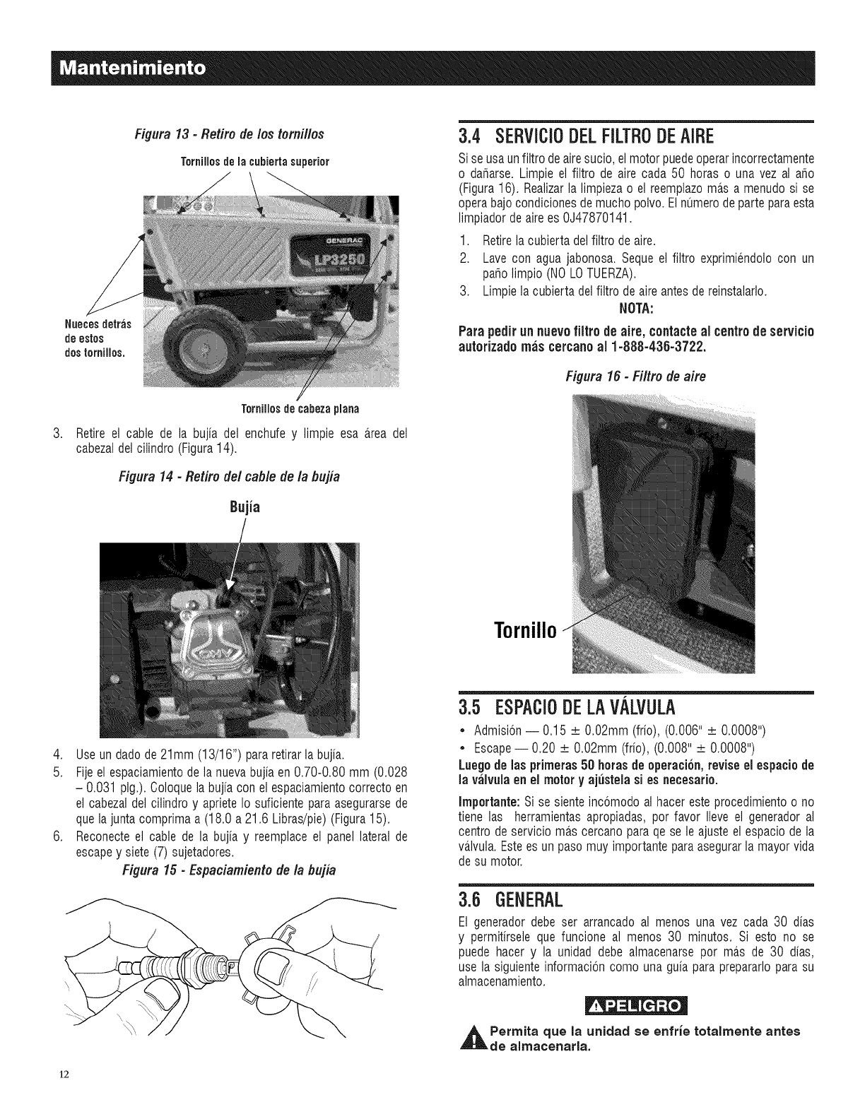
.
Figura 13 - Retire de los tornillos
Tornillosdelacubiertasuperior
Nuecesdetras
deestos
dostornillos,
Tornillosde¢abezaplana
Retireel cable de ]a bujia de] enchufey ]impieesa a.reade]
cabezalde]cilindro (Figura14).
Figura 14 - Retire del cable de la bujia
Bujia
3.4 SERViCIODELFILTRODEAIRE
Siseusaunfiltrodeairesucio,elmotorpuedeoperarincorrectamente
o dar_arse.Limpie el filtro de airecada 50 horas o una veza] argo
(Figura16). Realizarla limpiezao el reemplazoma.sa menudosi se
operabajocondicionesdemuchopolvo.Elnumerodeparteparaesta
limpiadordeairees 0J47870141.
1. Retirela cubiertade]filtro deaire.
2. Lave con aguajabonosa.Sequeel filtro exprimiendolocon un
paholimpio (NOLOTUERZA).
3. Limpielacubiertade]filtro deaireantesdereinstalarlo.
NOTA:
Para pedirunnuevofiltro de aire, contacteal centrede servicio
autorizadomas cercanoal 1-888-436-3722.
Figura 16 - Filtm de aim
Tornillo
4. Use un dado de 21mm (13/16") para retirar la bujia.
5. Fijeel espaciamiento de ia nueva bujia en 0.70-0.80 mm (0.028
- 0.031 pig.). Coloque ia bujia con el espaciamiento correcto en
el cabeza] de] cilindro y apriete Io suficiente para asegurarse de
que la junta comprima a (18.0 a 21.6 Libras/pie) (Figura 15).
6. Reconecte el cable de la bujia y reemplace el panel lateral de
escape y siete (7) sujetadores.
Figura 15 - Espaciamiente de la bujia
3.5 ESPACIODELAVALVULA
•Admision- 0.15 _+O.02mm(frio), (0.006" _+0.0008")
• Escape- 0.20 _+O.02mm(frio), (0.008" _+0.0008")
Luegode lasprimeras50 horasde operacion,revise el espaciode
la vaivuiaen el motory ajusteiasi esnecesario.
Importante: Sise sienteincomodoal haceresteprocedimientoo no
tiene las herramientasapropiadas,pot favor Ileveel generadoral
centrodeserviciomas cercanoparaqese leajusteel espaciode la
vaJvula.Estees unpasomuy importanteparaasegurarlamayorvida
desu motor.
3.6 GENERAL
El generadordebe ser arrancadoal menos una vez cada 30 dias
y permitirseleque funcione a] menos 30 minutos. Si esto no se
puedehacer y ]a unidad debealmacenarsepor ma.sde 30 dias,
use ]asiguienteinformacioncomo unaguiaparaprepararloparasu
aimacenamiento.
_Permita la unidad se enfrie totalmente antes
que
de aimacenarla.
12
3.7
1.
,
ALIVIACENAIVIIENTOA LARGOPLAZO
Dedrenajedeaceitedelca.rterdespuesdequeel motorse enfrie.
Rellenarcon la calidadrecomendada.
Quitelas bujiasy vierta cercade1/2 onza (15ml) de aceitede
motor enlos cilindro.Cubrael agujerode la bujiacon un trapo.
Tiredelarrancadorderetrocesounpardevecesparalubricarlos
anillosy el interiordelpiston.
,A. CUIDADO
Eviteel rociadodel orificio de la bujia cuandoarranqueel
motor.
3. Instaley aprietela bujia.Noconecteel cabledela bujia.
4. Limpielas superficiesexternasdel generador.Compruebeque
las ranurasy aberturasdel airede enfriamientoen el generador
estenabiertasy sin obsta.culos.
5. Almacenelaunidadenun lugarlimpioy seco.
3.B OTBOSCONSEJOSDEALIV]ACENAIVIIENTO
• Si es posible, almacenela unidaden interioresy cubrala para
protegerlacontraelpolvoy lasuciedad.ASEGORESEBECERRAR
LAVALVULAEN ELTANQUE DE COMBUSTIBLE.
• Cubra la unidad con una cubiertaprotectoraadecuadaque no
retengahumedad.
,_ NUNCAcubrael generadormientras el motoryla zonade
escapeest;in calientes.
13
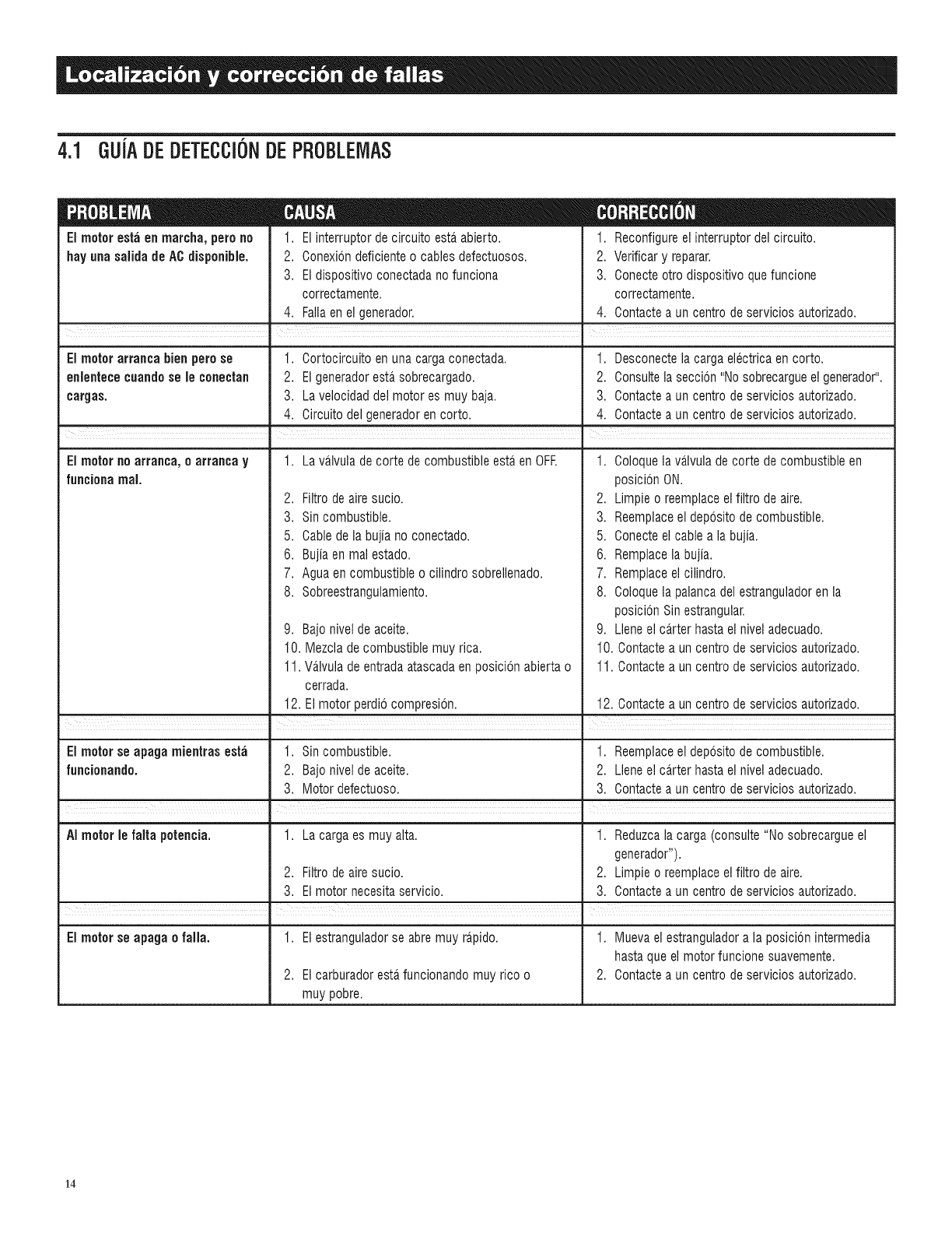
4.1 GUJADEDETECCI6NDEPROBLEMAS
EI motoresta en marcha, pero no
hay unasalida de AC disponibie.
1. El interruptor decircuito esta abierto.
2. Conexiondeficienteo cablesdefectuosos.
3. El dispositivo conectadano funciona
correctamente.
4. Fallaenel generador.
1. Reconfigureel interruptor del circuito.
2. Verificar y reparar.
3. Conecteotto dispositivo que funcione
correctamente.
4. Contactea un centro deservicios autorizado.
El motor arranca bien perose 1. Cortocircuito en una cargaconectada. 1. Desconectela carga electricaen corto.
enlentece cuandosele conectan 2. El generadoresta sobrecargado. 2. Consultela seccbn "No sobrecargueelgenerador".
cargas. 3. Lavelocidad delmotor es muy baja. 3. Contactea un centro deservicios autorizado.
4. Circuitodel generadorencorto. 4. Contactea un centro de servicios autorizado.
| I
=
El motor no arranca, oarranca y1. La va.lvuladecorte decombustible esta.en OFF. 1. Coloquela valvulade corte de combustible en
fuacioaa real. posicbn ON.
,
3.
5.
6.
7.
8.
Filtrode aire sucio.
Sin combustible.
Cabledela bujia no conectado.
2. Limpie o reemplaceelfiltro de aire.
3. Reemplaceel deposito de combustible.
5. Conecteel cable a la bujia.
Bujiaen mal estado. 6.
Agua en combustible o cilindro sobrellenado. 7.
Sobreestrangulamiento.
9. Bajonivel de aceite.
10. Mezclade combustible muy rica.
11. Va_lvulade entradaatascadaen posicion abierta o
cerrada.
Remplacela bujia.
Remplaceel cilindro.
8. Coloquela palancadel estranguladorenla
posicbn Sin estrangular.
9. Lleneel carter hasta el nivel adecuado.
10. Contactea un centro deservicios autorizado.
11. Contactea un centro deservicios autorizado.
12. Elmotor perdio compresion. 12. Contactea un centro de servicios autorizado.
J
El motor se apaga mientras est_i 1. Sin combustible. 1. Reemplaceel deposito de combustible.
funcionando. 2. Bajonivel de aceite. 2. Lleneel ca_rterhasta el nivel adecuado.
3. Motor defectuoso. 3. Contactea un centro de servicios autorizado.
|
AI motor le falta potencia. 1. La cargaes muy alta. 1. Reduzcala carga (consulte "No sobrecargueel
generador").
2. Filtro de aire sucio. 2. Limpie o reemplaceelfiltro de aire.
3. El motor necesitaservicio. 3. Contactea un centro de servicios autorizado.
.
El motor se apaga efalla. 1. El estranguladorse abremuy ra.pido. 1. Muevael estranguladora la posicbn intermedia
hastaque el motor funcione suavemente.
2. El carburadoresta.funcionando muy rico o 2. Contactea un centro deservicios autorizado.
muy pobre.
14

15
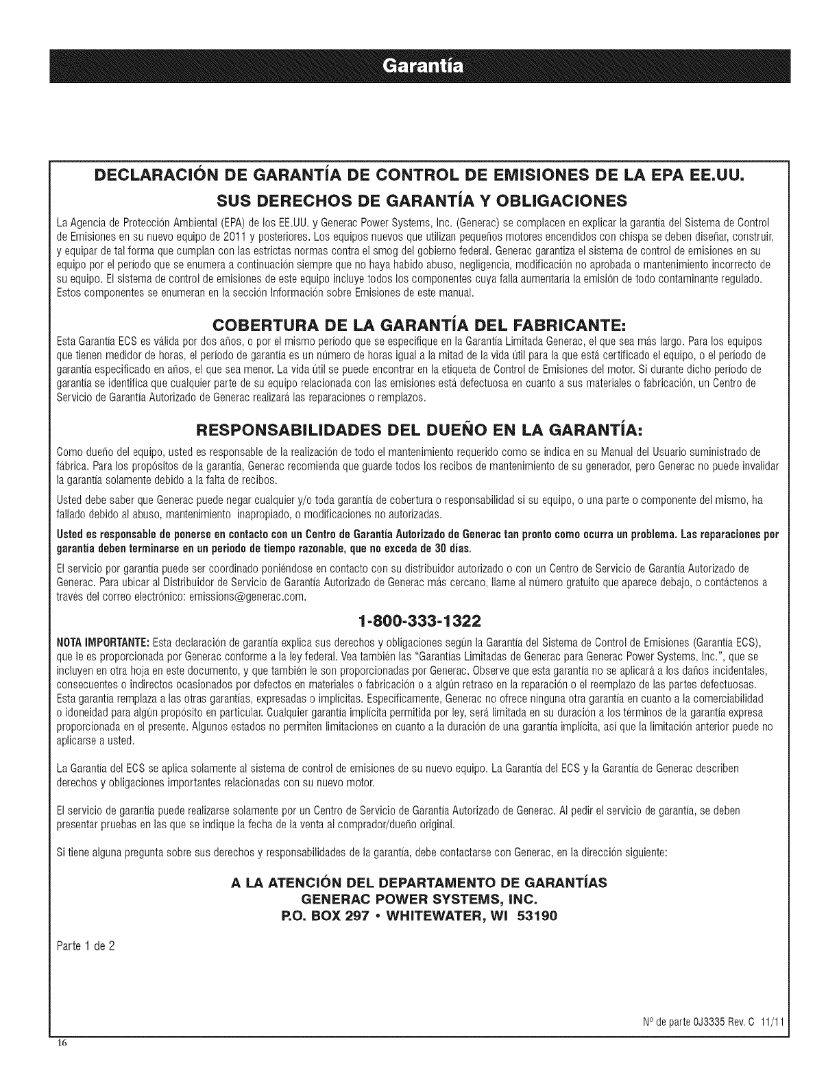
DECLARACION DE GARANTiA DE CONTROL DE EMISIONES DE LA EPA EE,UU,
SUS DERECHOS DE GARANTiA Y OBLIGACIONES
LaAgenciade ProteccJ6nAmbientai(EPA)de los EE.UU.y GeneracPowerSystems,Inc.(Generac)se complacenenexplJcarla garantiadel SistemadeControl
deEmJsJonesensu nuevoequipode2011y posteriores.Los equiposnuevosqueutilizanpeque_osmotoresencendidosconchispase debendJse_ar,construir,
y equJpardetai forma quecumplanconlas estrictasnormascontrael smogdelgobiernofederal.Generacgarantizael sistemade controldeemisionesen su
equipopor el perJodoquese enumeraa continuacJ6nsJemprequeno hayahabidoabuso,negligencJa,modificaci6nno aprobadao mantenimientoincorrectode
su equipo.Elsistemade controldeemJsJonesde esteequJpoincluyetodos los componentescuya failaaumentarialaemJsi6nde todo contamJnanteregulado.
EstoscomponentesseenumeranenlaseccionInformacionsobreEmJsJonesdeestemanual.
COBERTURA DE LA GARANTJA DEL FABRICANTE:
EstaGarantiaECSes va.lidapor dosa_os,o por elmismo perJodoque seespecifiqueen la GarantJaLimJtadaGenerac,el quesea ma.slargo.Paralos equipos
quetienenmedidorde horas,el periodode garantiaes un numerodehorasigual a la mitadde la vidautil paralaqueesta.certificadoel equipo,o el periodode
garantiaespecificadoen a_os,el queseamenor.La vida utilse puedeencontraren la etiquetade Controlde Emisionesdel motor.Si durantedicho periodode
garantiase identificaquecuaiquierpartedesu equiporelacionadacon lasemJsionesesta.defectuosaen cuantoa sus materiaieso fabricacion,un Centrode
Serviciode GarantiaAutorizadodeGeneracrealizara,las reparacioneso remplazos.
RESPONSABILIDADES DEL DUENO EN LA GARANTiA:
Comoduellodelequipo,ustedes responsabledela reaiizacJ6ndetodo el mantenimientorequeridocomose indicaen su ManualdelUsuariosuminJstradode
fa.brica.Paralos propositosde lagarantia,Generacrecomiendaqueguardetodos losrecibos demantenimientodesu generador,peroGeneracno puedeinvaiidar
la garantiasolamentedebidoa lafaitaderecibos.
UsteddebesaberqueGeneracpuedenegarcuaiquiery/o toda garantiade coberturao responsabilidadsi su equipo,o una parteo componentedelmismo,ha
failadodebidoaiabuso,mantenimientoinapropiado,o modificacionesno autorizadas.
Ustedesresponsablede ponerseen contactoconunCentrade GarantiaAutorizadode Generactanprontocomaocurra unprablerna.Lasreparacianesper
garantiadebenterrninarseen unperiadode tiernporazonable,qua no excedade 30 dias.
ElservJcJopor garantJapuedesercoordJnadoponiendoseencontactocon su distribuJdorautorizadoo conunCentrode ServicJode GarantJaAutorizadode
Generac.Paraubicarai DistribuidordeServiciode GarantiaAutorizadodeGeneracma.scercano,flameainumerogratuitoqueaparecedebajo,o conta.ctenosa
travesdel correoelectronico:emissions@generac.com.
1-800-333-1322
NOTAIIVlPORTANTE:EstadeclaracJ6nde garantiaexplicasus derechosy oblJgacionessegunla GarantJadel Sistemade Controlde EmJsiones(GarantJaECS),
quelees proporcJonadapor Generacconformea la leyfederal.Veatambienlas "GarantiasLimitadasdeGeneracparaGeneracPowerSystems,Inc.", quese
incluyenenotra hojaenestedocumento,y quetambienle sonproporcJonadaspor Generac.Observeque estagarantJano se aplicar_ta los da_osincJdentaies,
consecuenteso indJrectosocasJonadospor defectosenmateriaieso fabricaci6no a aigunretrasoenla reparaciono el reemplazodelaspartesdefectuosas.
Estagarantiaremplazaalas otras garantias,expresadaso implicJtas.Especificamente,Generacnoofreceningunaotra garantiaencuantoa lacomercJabilidad
oidoneidadparaalgunpropositoenparticular.CuaiquiergarantJaimplicitapermitidapor ley,sera.IJmJtadaensu duracJ6na losterminosdela garantJaexpresa
proporcionadaenel presente.Algunosestadosnopermitenlimitacionesen cuantoa la duraciondeuna garantiaimplicita,asique la limitacionanteriorpuedeno
aplicarsea usted.
La Garantiadel ECSse aplJcasolamenteai sistemadecontrolde emisionesde su nuevoequJpo.LaGarantJadel ECSy la Garantiade Generacdescriben
derechosy obligacionesimportantesrelacionadascon su nuevomotor.
ElserviciodegarantiapuedereaiJzarsesolamentepor un CentrodeServicJodeGarantiaAutorizadodeGenerac.AI pedirel serviciodegarantia,se deben
presentarpruebasenlas quese indiquelafecha delaventaai comprador/due[]ooriginal.
Sitieneaigunapreguntasobresus derechosy responsabilidadesde la garantia,debecontactarsecon Generac,enla direccionsiguJente:
A LA ATENCIC)N DEL DEPARTAMENTO DE GARANTJAS
GENERAC POWER SYSTEMS, |NC.
P.O. BOX 297 •WHITEWATER, W| 53190
Parte 1 de 2
16
NOde parte 0J3335 Rev.C 11/11
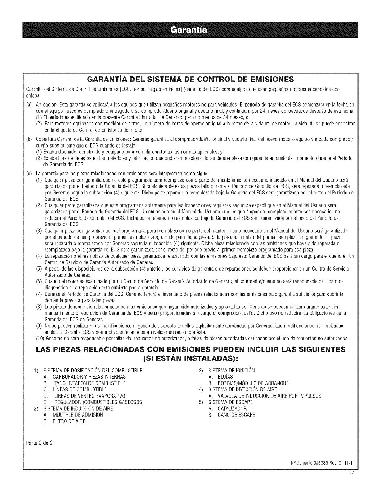
GARANTiA DEL SISTEMA DE CONTROL DE EMISIONES
Garantiadel Sistemade Controlde EmJsiones[ECS,por sus sJglasen ingles](garantJadel ECS)paraequiposqueusanpeque_osmotoresencendJdoscon
chJspa:
(a) AplicacJ6n:Estagarantiase aplJcar_ta los equiposqueutJlJzanpequefiosmotoresno paravehiculos.Elperiodode garantiadel ECScomenzar_tenlafecha en
queelequiponuevoes compradoo entregadoa su comprador/due_ooriginaly usuariofinal, y continuar_tpor 24 mesesconsecutivosdespuesdeesafecha.
(1) ElperJodoespecifJcadoenla presenteGarantiaLimJtadade Generac,perono menosde24 meses,o
(2) Paramotoresequipadoscon medidordehoras,unnumerodehorasde operacioniguaia lamJtaddelavida util demotor.Lavidautil se puedeencontrar
en la etiquetadeControldeEmJsJonesdel motor.
(b) CoberturaGeneralde la Garantiade EmisJones:Generacgarantizaai comprador/due[_ooriginaly usuariofinal del nuevomotoro equipoy a cadacomprador/
due_osubsJguientequeel ECScuandose instaio:
(1) EstabadJse_ado,construJdoy equipadoparacumplJrcontodas las normas@Babies;y
(2) Estabalibrede defectosenlosmateriaiesyfabricacionquepudieranocasionarfailasde unapiezacon garantiaen cuaiquJermomentoduranteel Periodo
deGarantJadel ECS.
(c) Lagarantiaparalas piezasrelacJonadascon emJsionessera.interpretadacomo sigue:
(1) Cualquierpiezacon garantiaquenoesteprogramadaparareemplazocomo partedel mantenimientonecesarioin@ado en elManualdel Usuariosera.
garantizadapor el Periodode Garantiadel ECS.Si cuaiquierade estaspiezasfaila duranteelPeriododeGarantiadel ECS,sera.reparadao reemplazada
por Generacsegunla subseccion(4) siguiente.Dichapartereparadao reemplazadabajola Garantiadel ECSsera.garantizadaporel restodel Periodode
Garantiadel ECS.
(2) Cualquierpartegarantizadaque esteprogramadasolamenteparalasinspeccionesregularessegunse especifiqueen elManualdel Usuariosera.
garantizadapor el Periodode Garantiadel ECS.Unenunciadoen el Manualdel Usuarioqueindique"repareo reemplacecuantoseanecesario"no
reducira,el Periodode Garantiadel ECS.Dichaparte reparadao reemplazadabajolaGarantiadel ECSsera.garantizadapor el restodel Periodode
Garantiadel ECS.
(3) Cualquierpiezacon garantiaqueesteprogramadaparareemplazocomo partedel mantenimientonecesarioen elManualdel Usuariosera.garantizada
por elperiododetiempoprevioal primerreemplazoprogramadoparadichapieza.Sila piezafaila antesdel primerreemplazoprogramado,la pieza
sera.reparadao reemplazadapor Generacsegunla subseccion(4) siguiente.Dichapiezarelacionadacon las emisionesquehayasidoreparadao
reemplazadabajola garantiadel ECSsera.garantizadapor elresto del periodoprevioal primerreemplazoprogramadoparaesapieza.
(4) La reparaciono elreemplazodecualquierpiezagarantizadarelacionadaconlas emisionesbajoestaGarantiadel ECSsera.sin cargoparaeldue_oenun
Centrode ServiciodeGarantiaAutorizadodeGenerac.
(5) A pesardelas disposicionesdela subseccion(4) anterior,los serviciosde garantiao dereparacionesse debenproporcionarenun CentrodeServicio
Autorizadode Generac.
(6) Cuandoel motores examinadopor un CentrodeServiciode GarantiaAutorizadode Generac,elcomprador/due_ono sera.responsabledel costode
diagnosticosi la reparacionesta.cubiertapor lagarantia.
(7) Duranteel PeriododeGarantiadel ECS,Generactendra,el inventariode piezasrelacionadascon lasemisionesbajogarantiasuficienteparacubrirla
demandaprevistaparatalespiezas.
(8) Las piezasde recambiorelacionadascon las emisionesquehayansido autorizadasy aprobadaspor Generacse puedenutilizardurantecualquier
mantenimientoo reparaciondeGarantiadel ECSy sera.nproporcionadassin cargoai comprador/due_o.Dichouso no reducira,las obligacionesdela
Garantiadel ECSdeGenerac.
(9) Nose puedenrealizarotras modificacionesal generador,exceptoaquellasexplicitamenteaprobadaspor Generac.Lasmodificacionesnoaprobadas
anulanla GarantiaECSy son motivo suficienteparainvaiidarun reclamoa esta.
(10) Generacno sera.responsableporfallas de repuestosno autorizados,o fallas de piezasautorizadascausadaspor el usode repuestosno autorizados.
LAS PIEZAS RELACIONADAS CON EiVlISIONES PUEDEN INCLU|R LAS SIGUIENTES
(SI ESTAN INSTALADAS):
1) SISTEMADEDOSIFICACIONDELCOMBUSTIBLE 3) SISTEMADEIGNICION
A. CARBURADORYPLEASINTERNAS A. BUJJAS
B. TANQUE/TAPONDECOMBUSTIBLE B. BOBINAS/MOBULODEARRANQUE
C. LJNEASDECOMBUSTIBLE 4) SISTEMADEINYECCIONDEAIRE
B. LJNEASDEVENTEOEVAPORATIVO A. VALVULADEINDUCCIONBEAIREPORIMPULSOS
E. REGULADOR(COMBUSTIBLESGASEOSOS) 5) SISTEMADEESCAPE
2) SISTEMADEINDUCCIONDEAIRE A. CATALIZADOR
A. MULTIPLEDEADMISION B, CANODEESCAPE
B. FILTRODEAIRE
Parte2 de 2
NOde parte 0J3335 Rev.C 11/11
1'7
GARANTiA LIMITADA "DE DOS Al_lOS" DE GENERAC POWER SYSTEMS PARA
GENERADORES PORTATILES SERIE LP
Por un periodo de dos (2) afios a partir de la fecha de la ventaoriginal, Generac Power Systems, Inc. (Generac)garantiza que sus generadoresSerieLP estaranlibres
de defectos en los materialesy fabricacion para los articulos y durante el periodo que se indica a continuacion. Generac,a su discrecion, decidira si reparao reemplaza
cualquier parte que, despues de set examinada,inspeccionada y probada por Generac o por un Centro de Servicio de Garantia Autorizadode Generac,se identifica como
defectuosa.Cualquierequipo que el comprador/due_o reclame como defectuoso se debe enviar a, y examinar por, el Centro de Servicio de GarantiaAutorizadode Generac.
Todoslos costos del envio dentro de la garantia,incluido el envio a la fabrica, correra,n a cargo del comprador/duefio y deberanset prepagados.Esta garantiase aplica
solamentea los generadoresporta,tiles SerieLP de Generac y no es transferible del comprador original. Guardesu recibo como comprobante de compra. Si usted no
proporcionaprueba de la fecha inicial de compra, la fecha del envio del producto por parte del fabricante sera utilizada paradeterminar el periodo de la garantia.
PROGRAMA DE LA GARANTiA
El uso por consumidores estagarantizadopor dos (2) afios. Las aplicaciones comerciales y de alquiler estangarantizadaspor un (1) afio o 1000 horas maximo, Io que
suceda primero.
USO POR CONSUM|DORE8
ANOUNO- Amplia cobertura limitadaen mano de obra y las piezaslistadas (se requiereprueba de compra y mantenimiento):
•Todoslos componentes
ANODOS- Amplia cobertura limitada en las piezas enumeradas (se requiere prueba de compra y mantenimiento):
•Todoslos componentes
USO COMERCIIAL/DE ALQUIILER
ANOUNO-Cobertura completa limitada (o 1,000 horas, Io que suceda primero); Coberturacompleta limitada en mano de obray las pieza(s) (se requiere prueba de compra
y mantenimiento):
•Todoslos componentes
NOTA: Paralos fines de esta garantia"uso por consumidores" significa uso personal por el comprador original en su hogar residencialo uso recreativo. Estagarantiano
se aplica alas unidadesusadas para la Energiaprincipalen lugar del servicio publico donde existael servicio publico de energiaelectrica o donde normalmente no
hayaservicio publico de energiaelectrica. Una vez que un generador se haya usado comercialmenteo para alquiler,sera considerado un generador no para uso por
consumidores para losfines de esta garantia.
Todaslas asignaciones del costo de la garantiaestan sujetas alas condiciones definidas en el Manual de la Politica del Servicio de Generac.
ESTA GARANTiA NO SE APUCARA PARA LO S|GU|ENTE;
•Los generadoresportatiles Generacconstruidos antes de junio de 2010.
Los generadoresportatiles Generacque utilicen partes de repuestooriginales.
• Elcosto del mantenimiento normal y de los ajustes.
Lasfallas ocasionadaspor cualquier combustible, o aceite contaminados,o por niveles inadecuados de aceite.
• Las reparacioneso los diagnosticos realizados por individuos ajenos a los centrosautorizados por Generacque no hayan sido autorizadospor escrito por GeneracPower
Systems.
Lasfallas, entre otros, por el desgaste normal, accidentes, mal uso, abuso, negligenciao uso incorrecto. Como contodos los dispositivos mecanicos, las piezasdelos
motores de Generacnecesitanservicio y reemplazarseperiodicamente paratenet el desempefioesperado.Estagarantiano cubrira la reparacion cuando el uso normal haya
agotadola vida de una pieza o delmotoE
Lasfallas causadas por cualquiercausa externa o de fuerza mayor,tales como, colision, robo, vandalismo, disturbios o guerras, holocausto nuclear,incendio,congelacion,
rayos, terremotos, tormentas, granizo, erupcion volcanica, agua o inundacion, tornado o huracan.
Los dafios ocasionadospor infestaciones de roedoreso insectos.
Los productos que seanmodificados o alterados de una forma no autorizadapor escrito por Generac.
Cualquierdafio incidental, consecuente o indirecto ocasionado por defectos en los materialesofabricacion, o cualquier retraso en la reparacion o el reemplazode la pieza
defectuosa.
• Lasfallas por mal uso.
Los costos detelefono, telefonomovil, facsimil, acceso a internetu otros costos de comunicacion.
Los costos generadospor "instrucciones del cliente" o por la Iocalizaciony correccion de fallas para las que no se encuentreningun defecto de fabricacion.
Elequipo de alquiler usado mientras se realizanlas reparacionesde la garantia.
Los envios nocturnos o los costos de envios especialesparalas piezasde reemplazo.
Las horas extras, o el trabajo en dias feriados o de emergencia.
Las baterias de arranque, los fusibles, las bombillas de luz y los liquidos del motoK
ESTAGARANTiAREEMPLAZAA TODASLAS OTRASGARANTiAS,EXPRESADAS0 IMPLiCITAS.ESPECiFICAMENTE,GENERACNOOFRECENINGUNAOTRAGARANTiAEN
CUANTOA LA COMERCIABILIDAD0 IDONEIDADPARAALGUNPROPOSITOEN PARTICULAR.Cualquiergarantia implicita permitida por ley, sera limitadaen su duracion a
los terminos de la garantiaexpresaproporcionada en el presentedocumento.. Algunos estados no permiten limitaciones en cuanto a la duracion de una garantiaimplicita, asi
que la limitaci6n anterior puede no aplicarse a usted. LA ONICARESPONSABILIDADDEGENERACSER_,LA DE REPARAR0 REEMPLAZARLA(S! PIEZA(S)COMOSEINDICA
ANTERIORMENTE.ENNINGUNCASOGENERACSERARESPONSABLEPORDANOSINCIDENTALES0 CONSECUENTES,INCLUSOSI TALESDANOSSONPORNEGLIGENCIA
DIRECTADE GENERAC.Algunos estados no permitenla exclusion o la limitacion de dafios incidentales o consecuentes,asi que las limitaciones anteriores puedenno
aplicarse usted. Esta garantia proporciona derechos legales especificos a usted. Ustedtambien tiene otros derechos de estado a estado.
GENERAC POWER SYSTEMS, iNC. • P.O.Box 8 •Waukesha, Wl 53187 • TE.: (888) GENERAC (436-3722) • Fax: (262) 544-4851
Para ubicar al concesionario aulorizadn mas cercano, visile nuestrn silio web www.generac.com
N.° de parte 0J4004 Revisi6nD 02/12
No de parte del Manual 0J2560 Rev. E (02/03/12) Impreso en China
