Generac 9067 0 User Manual STANDBY GENERATOR Manuals And Guides L9090244
GENERAC Generator Manual L9090244 GENERAC Generator Owner's Manual, GENERAC Generator installation guides
User Manual: Generac 9067-0 9067-0 GENERAC STANDBY GENERATOR - Manuals and Guides View the owners manual for your GENERAC STANDBY GENERATOR #90670. Home:Tool Parts:Generac Parts:Generac STANDBY GENERATOR Manual
Open the PDF directly: View PDF ![]() .
.
Page Count: 26
OWNER'S
Manual
II kW
AIR-COOLED
HOME STANDBY
GENERATOR
No. SOST_
h_Lm_i_ J
QENERAC
SAFETY RULES
31udyIt'4se SAFETY RULES cwe/ul_ before mstallm9
DEer,eng ,x se_,n9 th_ *qu*wn*_ Uecom* tam,at w*th
the Ownlr's Mnmualand wirethe gon_mor Sate eff_enl
toll_ a¢omWoncan be olMjnod o¢_y#the get_oq
propqMy ie_tlllled oflQmNld and mai_lllmKI M_y so_-
_ me causedb,/a toXvroIok_ow simile and_ndamen.
IJ nJes
Oenocac carmol pos$14_y nn_Opae eve_ possl4_e _.
c_'_3tlmco _n_ht tnvo4ve a hazard The wsmmgs m th_
Manull and o_ tags wxI dea_= omxod Io 1heequlpment ue
_we_'e noqadlqnclush'e Ifaprocodlxe, work memod oq
operMOng ItchnlqU4p no spOCtflcaNy recommended by
O0_O_ is U_('d. yOUfv'_JSIsnq_fy yourl_f _it _sale for
yo_ wI¢I olhefll You rnusl iklo n11_ curd lhe gene_Mor mN
noqbe _ _ remd_ed uml_e by Ihe pro=:edu_e,wo_
moShodor ol_r _to_vdquo you hew ctmsen
Gmn_l_ su_ls tt_iqW_S4 SAFEIY RUI.ES be copied
md (_,s_ed neer me standby elod_ system I_stdamt_
SAFETY SHOULD BE STRESSED TO ALL OPERATORS
AND POTENTIAL OPERATORS OF THIS EQUIPMENT
1 Fo_firesere,/. I_ equqomemmu_ bopropm_ installed
and _ InstMh4on must Mvmys_m com.
pnmco vmh_cede_,mmdude _end r_gule
i_m LOad sl_ee_dr_a_ekv.,Ir_w'xlt)uddl_ co_
mumbe _adh_ed 1o ReEulmicm_est_lshed by the
SMMy w_d Hedllh Admlntsfrldlon(OSHA)
mu_ be oompllodw11htnmk_Uo_,theganormo_and r_al*KI
mmpo_m_ rmmtI_ *nmJk_ comple_V m coneonnanc*
v_n I!_ rn_r_e,r_'e _ amclr_omnxmdatkms
Fom_v_g proper W_U_mon. r_eV_ mum be don* thet
rw_gh_aRq.'a_ucttsa_o_tjl=#_ mudmnde0"It m _o_m-
l_lerce wllhl_ch com_. l_w_(lerde,llms m_dreg_lons
2 Do _x_n(_kem_ndthe gonenmx V,lpe upall_eland
c_pemw_ KoepmeIres B,.,_nd Ihe gan_mo_ckmnand
line ol _
3 Anm unot_mmed Ikm o_¢oo_ngend vonm_r_
ate roqufrt_ fur o_, exl_n_g tow and namnt_t
_. _1 anl_ne c_ml_n_n oo nm m_r tbe *nm_m_on
com_ Io bo¢omo o_Me_a_l Tho g_m_ollor MUST
be I_ ou_oml
4 The Mlgln_ oxhoJM IlyllMm _i_le off DEADLY cwIDon
mm_odclebee Thi_4ml_J_ gin. I_brmm_ In _clem
0nol_a Ih* emeuoa Wndemgroque_ 1"_e .turn _.o
I=OO.NIMIIly_ oxhaumt_ onl_ m_ybukl0'_=_morn
o_1 Isypeq_o o__na, Tho _MUST be _
t_led ouldoen, wr_o a_M_p_o vv_l_k_, F=a_e
S Keei_hende, ro_', cl_hi_ 9 e_c. _..._yf, omdn_e bells,
f, The Ndon_ =le¢_€ C_x_ mqulr_ em t_r hlne and
*,eme_ _e_ly omm_l_ w._m o( qhe9.n_m_ bo
I_O1_#_ mnM¢*_l Ioen el_mvod wnh Emu_l Locel
_._r_ ood_, mmy mo r_ pna>_ Oroundt_ _th.
sh(x_m lh_evontolm gro_,Jleu@
7_ll_tli_i_on Ofthis home standby el_clr_:al qy_.lem
*Scorn_ Ihe generlto¢ onglne n_ly crank and slarl agany
,me _ _ Fo_o,_n_ .wlup _'ansle_ o_load or
cu_s to _STANDBY (OoneqNo_) power source vv_ o_cur
TOprevM4 possd_e Ir_uryIh_ m_t_ be cEused by Such sud
den stirrup and transfer, llways set the gonerator $
Manual/Off/Auto Synch Io its OFF position before wo*'kmQ
o_ ,qu*pm,_
8 Exlremoff high and danE_ous vo_eges are deWered Io
the frensler switchfrom Irte UTILITY power source taxi from
_e standby g4m_alo¢, whan me lafle¢ _ru_r.n 9 Contact
wl_ bare w_ms. lewndnals,c_)necll_, etc c_mresult m
ve*y hszfdo_S. ".,ndpossli_y LETHAL elechlcal shock
9 '_he_ wod_n_o_ _11sIKFJ_:)m_ recn_n M_IM aflttme$
Never wock on the _whe_ p_yslCally O_menlaRy
10 Ne_ handle any kind o_ _ de_ce wh_e stand
m_ in _*,llter, wh_ t)WMOM, mwt_e harris or feet are wet
DANGEROUS ELECTRICAL SHOCk" WILL RESULT
11 kicie@o_llcO_ki_cdlusecJbyoklcffk_Ishock shame
s_urce o/eleclrt_l power dow. 8i or_e If tt',_ cannot be
done. tree Ihe vlcllm from me Hve cor_k_to_ AVOID
DIRECT CONTACT WITH THE VICTIM Use II dry board
dry rope. o_olh_ non-eonductV_ implemanl to Irou It_ vk:
.m from Ibe Nv_ cBnduck_ _vtclm b _
CPR (a._o-puamom_-nnuscn_on) w_ _*_rr_Sc_
12 Gaseous kmts suOhmsnatxlli _1LP (_'op3ne) _as _e
o_ EXPLOSIVE The kJ41supply sy'st_ must be
_y W_Nle_ _ au:cx_cmncow0_ a_.,al_o _e4-gas
cod_ Befon_phndr_ me hcx_ostamd_ ot_lttc systom ling
s_co. mefuM systom lln_l nmst be pmtN¢ly purged and
_m_l _nan_x_nm w_ _:01_e code Fonow_
*.stakton, me _Wst*m mu=tbe k'4peo_ p*_x_c=oy
f_ le4M NO IO01_O0 I_ IMlewMfl_l
m_e_ _dm_e_d o_(mecu_ p,m 0m_llm
14 Koepmfifooxllngul_M on handnomrIhe gem)rMm"set
Ex'mgu*_m_ ml_ "ABC"by me Nmk_l Fire Pro_lon
Ata._n _m m _ u_ w*mmemmlby ,k_
flmIlm, wI_ RI ule N you htvo a_y qu_lonl ip_'tallnlngto
_.'. o_0ngu0mor=,meoun yourIoc=l nn_¢lopau_nw_
15 N,_w wNmn,*ry_wond_ _ _ W
.kmWy _mduct= m amd mm c_,m, ¢_mg_wous
oOecfrtc_gehod_
)-&I_|RI: I)_SPIT[ THE SAFE OESION OF THE QIEN.
ERATOR AND TRANSFER SWITCH, OPERATING
THESE OEVICES)MPRUOBNTLY, N_GLECTING THEIR
MAINTENANCE, Of_ CAIqELESI|NESE CAN CAUSE
POSSIBLE iNJURY OR DEATH. TH_ GENIERATOIq ffi
POWERFUL ENOUGH TO O_LIVER A FATAL ELECTRI_
_AL SHOCK. UTILITY POWER _VOLTAGE
DELWERED TO THE TRANSFER SWI_'CH CAN ALSC
CAUSE FATAL ELECTRICAL _X_. ONLY RESPON
SlILE ANO CAPAI.E PERSONS SHOULD lie PER
MIT_O TO OPERATE Oil MAINTAIN THIS EQUIP
MENT.
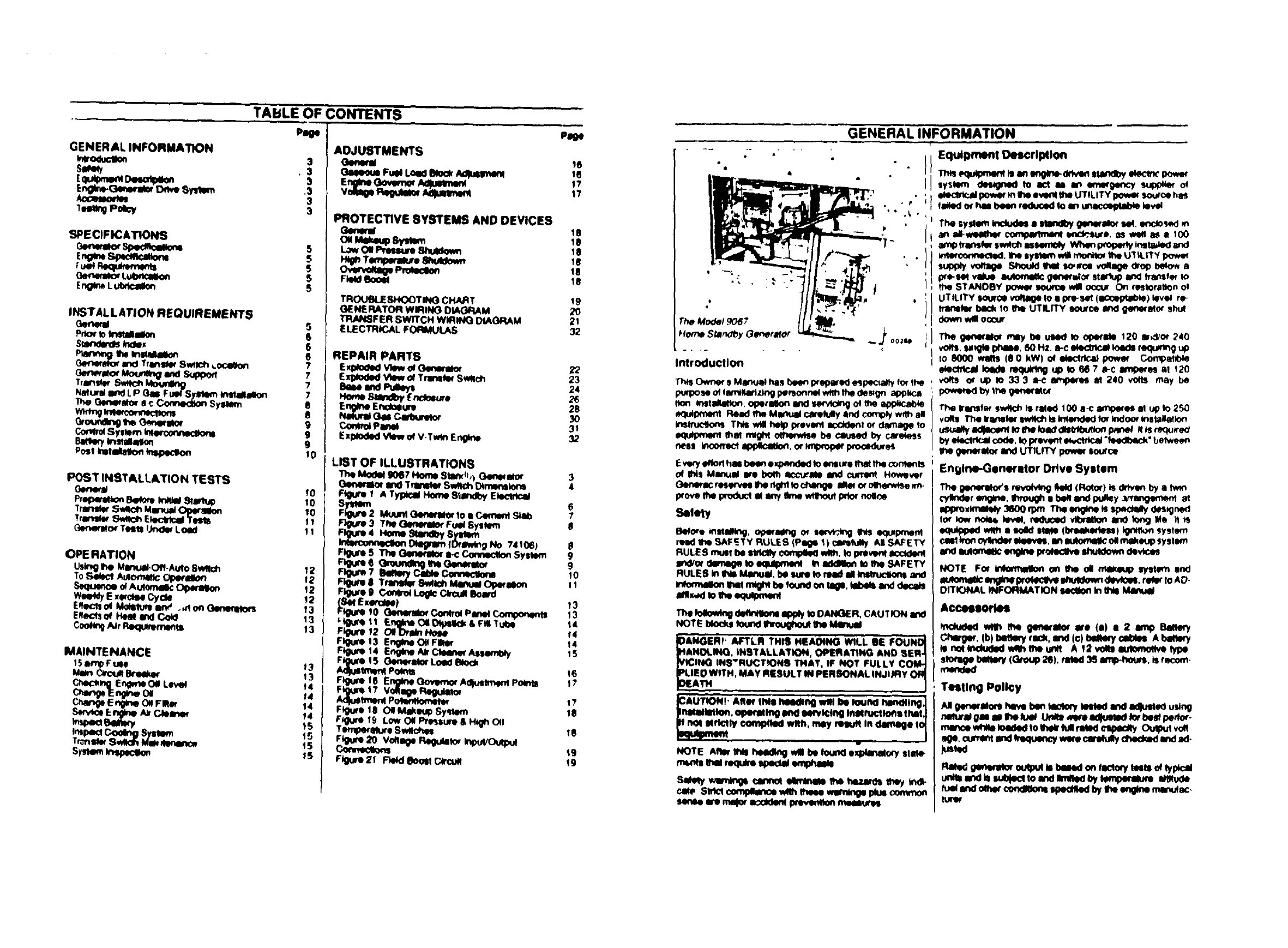
TABLE OF CONTENTS
Page
GENERAL INFORMATION
we,m0Poky
SPECIFICATIONS
E_LU S
INSTALLATION REQUIREMENTS
_meml 5
Prk:u'fo InlUlIikq
Smr_Wds/ncMx 66
N_um an_ LP O__F u_'Sx_ _m._m_
The Gen_alor a c ccnnedton Syl_
w_tngmconmcttom
_,o_dtng me_qto, e
ControlSys_m'n _ercertmmtam
Post Inimtdon k_Oeclk)n !0
POST INSTALLATION TESTS
Oem_aJ !0
Pf_ern_ _ _ _m_ Io
_ran_ S_ch Mmnuj O_m_n 10
"Vrans_WSwttOh Ek_'tlcal 'Tests 11
eene_m Tests I_ Lo_ 1I
OPE RATION
Using ihe Mlinua/-C)fl-Aufo 8wllch 12
0 Select Adonvnk: Ope_dcm 12
_KIu°_ °_ A_10mak: OPerllk_ 12
WeeMy E xe_cise Cycle !2
Eeect_oe Moisture w_, .,non _t3
Eflo'-*'tsof HeM end Cold 13
c_ _, Req_m 13
MAINTENANCE
t3
t4
Change E_rm_ ONFirm f4
14
15
I__ smem Is
Tron_' SW_ M_ _n¢_ 15
S_om _ _S
Pl_e
ADJUSTMENTS
Oene_ 16
GIOeCmo Fuel Load BloOkAdluslmonl 16
v_i0e _ _q.mmm _?
PROTECTIVE SYSTEMS AND DEVICES
Oemn_
_'_eTem_m,,re a_Mo_
10
'Be
18
_e
_o
_e
TRO_SFKX)TING CHART 19
GENERATOR WIRING DIAGRAM 20
TRANSFER swrrcH WIRINCI DIAGRAM 21
ELECTRICAL FORMULAS 32
e 4
iGENERAL INFORMATION
r'
- " " Equipment Descrl_lon
REPAIR PARTS
ExModedVlowo_(]Wwlo_ 22 Introduction
Elpkx_! Vbw oeTrllnl_ Swath 23 Th_ Owner s Ma_,el hae been ;xopa_ e_peoalty fo_Ire
Sell i1_ Pul_
equipm_ml RemdItte Ml_ud camf_ly ind comply w_t_ al
mtruct'ons This will help Wevonl acd0enl or dav_a_e to
Exptoded View of V.Tw_ Englne ._ _I_sl mlgh_ o_f_n_tse be caused by caro_ess
LIST OF ILLUSTRATIONS _very_has beenexp_.xl_ to ensurethatme o_n_m_s
t3enm'Im_Modil_d9067TtlnM_Home8tw_,),Swt_hDtrner41o_sGNm_al°r 43 Qenm.i: resm"_m 1her_t_l Iochange°_INs Mmnu_l Ire bo_ a_-_J_m anddlmoroff_erv_se.'n-curr°_lHovmmr
_3 The OImerItor Fu4# Sy|lem 8
IntMom'ln,_lon _ IDrllmdn_ No 74106) mad _SAF_.TY RULES (Psge 1) €_r_lty _dl SAFETY
Figures The QeneiIlOr I-c Conneclton Sysiem 98 RULE S muef be etrt_ ¢'_ wllh. lo p_vlm_ ac_Idenl
Figure 7 BIftmy CIMe Conneclto_ RULES In INs Manu_. be lure to reed allIn_ucllonl and
_$ Tmm#_ S_kc_ ManuwOp_mlon
_um9 C_r_ _om_ _mx,,_ to meequ4_me_
(S_ E_e_el 13
Figure 10 Genlmnlm Con#ol Panel Compomm_ 13 The !olowl_ d_lnllonl IlPl_ to DANGER, CAU TION Ind
_'tS_ 11 Englnl OI O_lk:lk & Fill Tube 14 HOTE MoOkl Iound IIl'oiJ_to_ Ihe ..M_
F_um 12 OID_n Hoee _4
Fl_uro 13 Engine O€ FiNer 14 DANGERP AFTLR THIn HEAOtNG" _LL IE I_OUNO_
F_jm !4 E_nglneAir _Assembty 1S H&NOLING, INSTALLATION, OPIF.RAT',NG AND SER._
_J_e 15 GW_rll_r Loed Block VICING INS"RUCT_ONE THAT, IF NOT FULLY CO1_
Ad)uItment Poln_ !6 PLIED WITH. MAY RESULT IN PERSONAL INJURY ORJ
, ,, !
Ftgum 18 Oil Makeup Sy_em I 8 Inslilitm, qpeflltlng lind talcing InoUuctlofll IhIt_
Figure19Tempe_Mue_L°w O(i Pm_uurl/' H__Is.c_m 18 oqullmm_"noi elrtctty €omplle_ wllh, may n_ In damage ,€_
,_9 NOTE Afire. _heed_ vdll be found ex_ocy siate-
FIgu_ 21 F_d _o_l C_o_ 19 ml,ntl thll mquke ipedl emph_lo
S_my wm'mgs canrm elnvn_e ths t_za_s mey tnd_
caw Strut cc,m_m wiremese wemlngep0ueoomm_
_mas we _ I _ n,_as_
sysWm _to act as w_ eme_ge_'y _o_
_power m gle even( the UTILITY po_4K so_'ce hes
reded o_ has been reduoed to m unecmptal_ lev_
T_e syNl_ ll_kxltl IItlndl_ _pm_Mo_ es(. encto,_<l e
an iI_ wNm_ _pilmonl **_*,:s_*. ,,_ w_t is a 100
am_ Wansk_ sw_t_ esasmoly Wh_ prol_e_y *_stile<l and
Inte_c_me_led. 1hesystem v,41i_the UIILtTY pow_
supply voltage ShouM th_ scarce v_tage drop _n
p'e-sm vllue autom_ _In_wui_' stlil_ and Wa_sf_ to
fl_ STANDBY pow_ _xwce w_ occur On rostOril_n ol
UTILITY _¢e _ to • _(_) _v_ r_
tmrmlW back to I_e UTILITY source imd gen_rM_ Shul
dram wl occur
The ge_erlloe r_ be used to operlde 120 I,d/or 240
_#s. sm_giephaas, 60Hz. n-c ek_lrlc_ I_eds requr_g Up
to 8000 w11s (O0 kW) of _power Compold)le
eklOlfl_d k)_ls requlrtng up to M 7 _t-c unperes al 120
vOfl$ Or up to 33 3 I-C B_tlNKqtSM 240 yogi may be
The transfer Sw_k:_Is riled 100 a-c amp_es al up to 250
vO#e The vw_fer switch is Inlended k_ indom mstaNetkon
_ _ code, _ _ _d_ _be_" beh_en
the _n_M_ _d UTILITY _w_ I_x_
Engln_GlnMMor D_ve Syllim
The 0e_eq_rs revo_ _(Ro(o_) is d_*_ by a _n
€_Ik_ler englne, ll_m_0h i b_q randix_ey ;¥rang_mxml at
ni_ro,_'y 3eoorl_t "r_eengine_ _€._<_aay€_s_gm)d
equipped _ • sold ltMl (Ixeekede1_) _system
ca_ kon cylndm' m, mnauton_l_ o41makeup sysI_n
and lu_xnI_ e_llne ixoleclve lhuldown devlc:es
NOTE Fm _o_ the oll mem_p we_m _
IulomIIlC OrlglnoIXOkl'31_ IlilUldmm dlvt_ml. _lo AD-
D_NAL _FORMAT_N _ In INs
Acceel_ee
_me generator we (,,) •2 amp 8e._y
chwO_, (b)t_en_ r_, er_ (©)bem,rycoUasAtm_
le no( Indudod wllh I_e _nll A 12 voltl _lype
r_edllto_ (Group 2t_). rated 36 imp-houre, is recom-
Testing Policy
Ange_r_ here bentac_r_ teetedaml a4ust_ using
rn_ce _ _to_ _ _ed_ Ou_
_ _ _ le be_d onrectory _ts o_typi_i
_i_ w_€llum_)le_ to md Im_ _y m umude
_ _ndDew cm_nz mmlk4 by_e _gm men.at,

i I I J i i
iGENERATOR AND TRANSFER SWITCH DIMENSIONS
TOP OR PLAN VIEW
i Ill
TRANSFER,_(35.9on)., !
SWITCH ALL DIMENSIONS IN INCHES
CENTIMETERS
14.12 , |38.13
2.oo 2.00 r .... (96.8cm)
(S.lcm)-__-_ (slcm) o, /
' ', r------- (1.3cm)
_'-r [
For 114Inch (M6) Bolt,q
20.24
(5t.4cm)
0.50
11.3cm)
0 228
(o SScrn)
Hot,JS
(4places)
1.97
(5.0cm)
[-
22.37
(568cm)
___-J
[- 1.97
(5.0cm)
22.37
(se.san)
BAI"rERY
COMPARTMENT
I
iI* ); Ij I
___._ I
7!8" Dla Knockout
28.75
(73.0CM)
1-1/8" Dla Knockout
_ /
GASEOUS FUEL
CONNECTION
0 87
(22cm) -"
_/_/GROUNDING LUG
EXHAUST OUTLET
m
AIR OUTLET
39 0
..... (99ocm)
AIR INLET
RIGHT SIDE VIEW REAR VIEW FRONT VIEW
SPECIFICATIONS
Generldor Specifications
Mo<_ Nlumtx_
I_,eedMaxlms_ Conllnuous
.-c e0wer _
TFuel Requirements
9067-0 The genecMor has beer= ticIory IeSled ind adjusted uSm9
8000wllltSdl0kW NMUrII(_BBs_Jft_I IfLPg_l(l_opanQtl$lobe_Jed tl_
1_ an(l_or 240" system must be cea_usted =is outlk'ted m #m ADJUST
1 0 MENTS seclton of ff_ MD'luI
RailedMaJdmum Co¢'_nu_s Load Curre_
At 120 volts _c _7m_ NOTE G4m_alor mexm_m wenage rating and ,_x_ne
At240 roils e-c 33 3 ampeqes
1.Pha_e
Rale(II-c Frequm'_y 60 HZ"
0dven Sired of Rotor 3Fr'00q_n"
of RotorPo_s C2ross
Imulaeon
_W/r_w Sysl_m F
rate(I ho_el_wef _11be _flec'ted by Ihe type ol fu_ u_=d
,e the speO¢lc luel s Blu Iheal) coment Wattage and
ho_sepowe' mey also be affected by amD_nl mmp_,ratu_e
Ixessum aa_de andom_cond_ons speci_ledbylheen
g_e m_nuf_"tur_r M_xm_m po_*_ _1 deo'o_s_ ap
pm=m_Mety 3.1 '2% for each 1000 feeelibove sea leve_and
w_l(leo'ease_nlMdltlO_ll !%fo_each 10 FabOveF,0 F
GeneTator Lul_lr._tion
i
nloA_om moth_ _tedtd
DANGERI IT IS NOT INTENO_D THAT THIS mSTAL-
LATtON INFORMAllON SHOULD BE USED BY ANY
UNQUALIFIED PERSON(S) FOR THE INSTALLATION
OF ASTANDBY ELECTRIC SYSTEM. IMPROPER, IN-
CORRECT OR UNAUTHORIZED INSTALLATION OF
THIS EQUIPMENT IS EXTREMELY HAZARDOUS ANC
MAY RESULT iN Df.ATH, SERIOUS PERSONAL IN.
JURY OR DAMAGE TO EQUIPMENT AND_OFi
pROPERTY.
Prior to InstldlMtOn
Pdm to Imt_k_k_ of Ihe home standby_sy$1_m.
re(:he_ me ragngsot bornme gmww_ and I_e nns/e_
)wgch T I-,e.'_,componemsmustt_ =l_emt_mdiemerm_"
tmumcoqnectedetecVtc4dtou_landmint Ihx) bt tullycom-
t_,,_themt_ v_4mgt le_ eun't_ttm_tt'tq_
cyof rneei_ imndceentrllnc_ P_Inef_'rPmPe_mtl _
_io_ shou_ be Wepemd_nm w_hIXoP_ altm_on
to me_har_al _ele_mcl _ _
The mlom.mr_nm tt_ MimuMi_ ofkm_ al mgu_e Iolld
youtntSnallzm9yourInslillllon p_lns Muct_of me Ineli_
_l_n _me_on *sr_st_lly _mer_ m n_um _ews
no_poss;blyknowof everymst_lMIonposslb._
Standards Index
In the absenceof pmtlnemstandards codes regul_ons
md_ theloeow,r,gp_t_,tW_edntom',_eont_x,kt_ may
be useda_ w_k_,ls_on gu_e _o¢;hlsequ_ment
I NFPA No 37, STATIONARY COM6USTION ENGINES
AND GAS TURBINES iv•lMl_e #ore the _Fire
Pro_e_ Auoc_llon. 470 _Avenue Boston MA
0_2t0
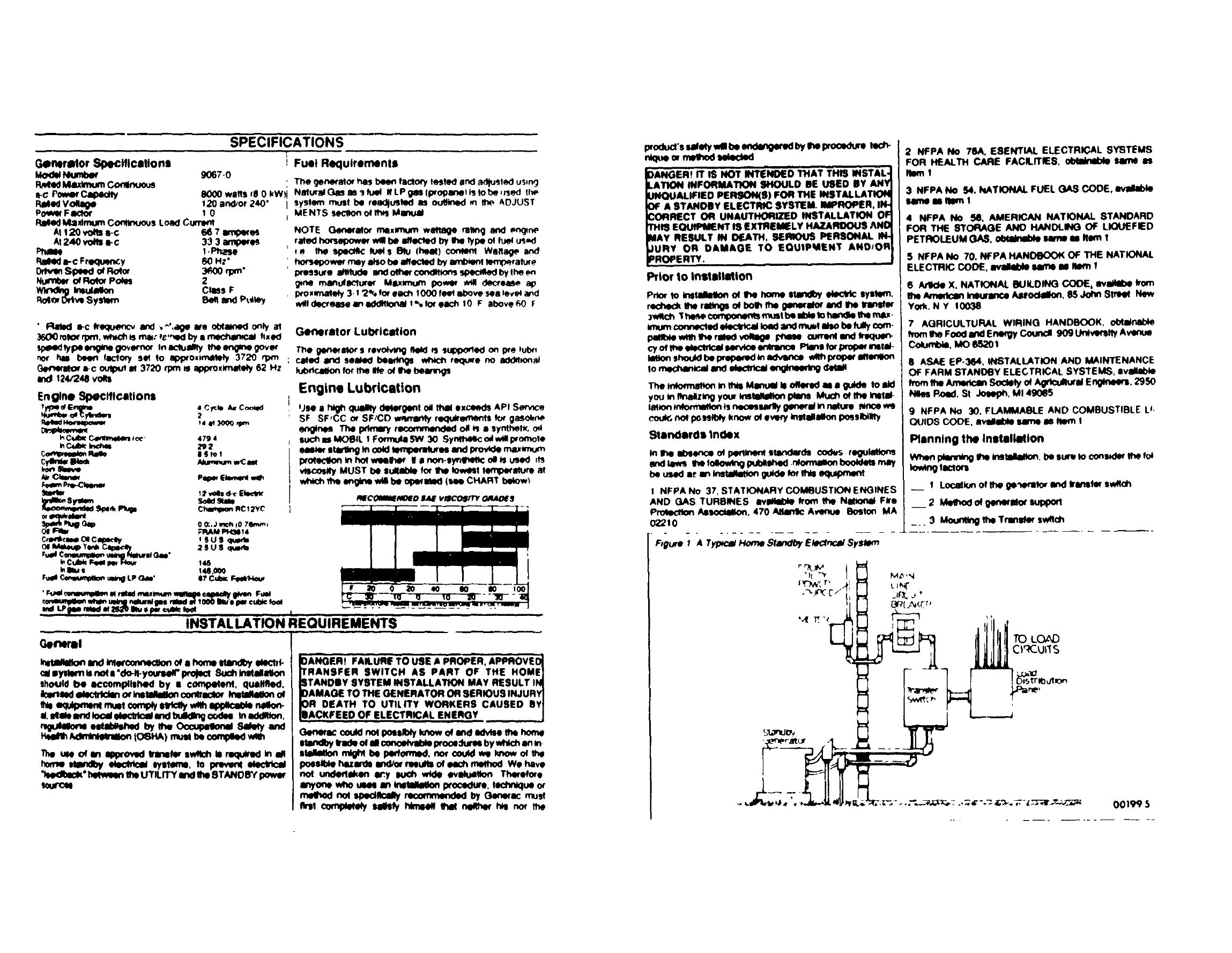
F_gum f,4 Typ_c_ Home Standl_/ Ek_:lrP..._ Sys_n
2 NFPA No 76A. ESENTIAL ELECTRICAL SYSTEMS
FOR HEALTH CARE FACILITIES, obtimlble _ m
Item1
3 NFPA NO S4. NATIONAL FUEL QAS CODE.
ume m Ilm_ 1
4 NFPA No _. AMERICAN NATIONAL STANDARD
FOR THE STORAGE AND HANOLINO OF LIQUEFIED
PETROLEUM GAS. _ _ as Rein I
5 NFPA NO 70. NFPA HANDBOOK OF THE NATIONAL
ELECTRIC CODE, _ ulme -= Mm I
6 Arlk:le X. NATIONAL BUILDING CODE, avilM)e f_xn
m_ Anmlcan In_,rance A_od_Eon. 85 John Stre_ New
York. N Y 10038
7 AGRICULTURAL WIRING HANDBOOK, oMl_n_b4e
hornIbe FoodandEnergy Coundl 909 U_vendly Avenue
Cok_t_, MO e520 t
8 ASAE EP-3B4, INSTALLATION AND MAINTENANCE
OF FARM STANDBY ELECTRICALSYSTEMS. •vJlM_e
Wornthe Ameec=mSode_yof Ag_tcumur=lEng_neers.2950
NI_ P_d. St Jowph. Mt 4g0_5
9 NFPA No 30. FLAMMABLEAND COMBUSTIBLE U.
QUIDS CODE. m,_l_ble same Is Item I
Planning the Installation
wbe_ p_ lhe Ins1_iiton. be sum Io cons_er lhe fo_
lowingtaClml
__ tLocation of tim ge'_emto_ and nnstm swRch
2 Mettx_ of gemxm_xsul_
_.. 3 Moun_g the Tmn_ swam
M_ 'N
LIN{"
', :_
00199 $
4 Natural gas fuel system requirements
__ 5 [P gas fuel system requtreq_nts
_ 6 EleClncnlconnect_ons
7 Automati_ co_ntrolsystem conne,:bons
__ 8 Prep,_'atlon Before InRi31Starfup
9 Batten/ Inslaltebon
10 Initial Stirrup and Testing
Generator and Transfer Switch Location
Ge_retor Location In, tail _e generator ouldoors and m
an aria where adequate coo_ng mr and yent_atmg a_l /_11
be evaiteb_ Remember exhaust gases contain deadly
carbon _xlde gas and WOf_r ventllatwn is requwed to
dissipateexheustoutp_ Theenglne generatorrequTre$ an
adequate, unobstructed flow of Coo_ngmr for p(oper opera
tton
OANGER _EXHAUST GASES CONTAIN DEADLY
CARBON MONOXIDE GAS. 1HIS DANGEROUS GAS,
IF BREATHED IN SUFFICIENT CONCENTRATIONS,
CAN CAUSE UNCONSCIOUSNESS OR EVEN DEATH
OPERATE THE GEhlERATOR ONLY IN OPEN, WELL
YENTILATED AREAS. WHERE EXHAUST GASES
WILL NOT ACCUMULATE AND ENDANGER PEOPLE
_'HERE MUST BE NO POSSIBILITY OF EXHAUS1
;ASES ENTERING A BUILDING OCCUPIED BY
)EOPLE OR ANIMALS
Install_generatorwhereg(ass, leaves snow, arc. wel
r_4 accumutatleand obstruofcoofJogair openingsm its
_t #prevNlng vv_xtzare Nk_y to causel_ock
age oflhe coo_ av openings,youmay wishto ¢OnSKN_
theuse ol a wtndlyeJ to p'otecl me generator
The Install_ mu_t also consider wate_ levels at the resist-
laiton site Never Install the generator on low ground, where
*atm m6gl_dse and tndanger _DeufCt
Fk_Mly,Insleit Ihl geNcator lul €oes UIx:411bteIo the fuel
suPl_ TI_ wM reduce Ihe cost of pq_tg nine
Alow _l, Nlua_ room|m_uncl=it tide. of ff_, ge_eratmtof
m_nWWnm, mm_i _ml r_ Agenarat n_e mm slow
mleml 3 hN_of c_mmn_eon Jl m o_t_ un_
Trm SwNch LOCMIon" toMait the _lntfet switch m-
_oore..,= close u pm.dil_le _ I_} LrTILrrY ix, we_ seun:e
_l_tc_ ser_ce e_,rmlce This wl reduce me coat of
Oenerator Mounting and Support
(]llm_fato4' moqJnlk_ dthleflato_ ire ehotwl on Pl_e 4 The
Wm_ocs comp.rlmem encmum sh_ld be seox_
mounled los _.m_¢ sMi_, uslnp 1/4 th0h mNon,y typ_
_b_ _ wmd_ I_1_ to__ _ The
Gramme mb should Ix_ M Me_ 3 Inohe_ mk:k and sheuM
oxle_l IN;y(nd the €omperlmen¢ at lesmt 3 inches on aN
€des 8eeFIgum2 BetwetolevatmesMb, sothatme
gont_tor l0rooa_ ona tovoteurtaeo
F OutP • Mount the Generator to a Cement S/,JI3
iS 43
38 13 _leg _:m)
196 8cm) i
F
/,
/
/
I// CEMENT SLAB
-y
Transfer Switch Mounting
See Page 4 for Transtor Sw_tch mounting d_m_ns+ons
Moun_the sw_tch to a strong,, _ suppm'flng struchJre that
can adequately support its wetghl it necessary _vel Ih,_
sw,tc_ Is prevent d|stod,o_ Th0scan be done by plaanq
washers befween fhe swtlch and supporting struOure
when levekng m necessary
AUTION_ Never Inl_ill the trlineter swllch where]
e|efl corrosive quids, or lny liquid might drip onto_
en¢lolure Prots_t Iho Switch egllnel dust dlrt I
Olslure, construcUon grit, end corrosive vef.ols mi
I limit J
Natural and LP GBS Fuel System Installation
When plan_mg the fuel supply system instal_lofl keep
fuel ppmgrunsas sh_1 es possible forcostreduc_m
DANGER! GASEOUS FUELS ARE HIGHLY EX,
PLOSIVE THE SLIGHTEST SPARK WILL RESULT ll_
FIRE OR AN EXPLOSION ALL APPLICABLE FUEL,
GAS CODES, STANOAROS ANO REGULATIONS
MUST BE STRICTLY COMPLIED WITH FOR SAFETY
INSTALLATION OF GASEOUS FUEL PIPING AN r
COMPONENTS SHOULD BE ACCOMPLISHED BY _1
COMPETENT. OUALIFIEO GASEOUS FUEL TECH
_ICIAN.
NOTE The lollow_ e_omtlton I_ providedto islsl
_s fu_ ted_nk:_n _npl_nnlngt_e InatilMlon o_the
fue4supplysysNm_ In no way mustt_e In_om_ton be _
t_ix_d to con_lclw_ idol, stateor nat_ guol.gas
Cocalul_wqhyourgel |lUp orIo_it Ikwmarshal
_any questionsshouldwIM
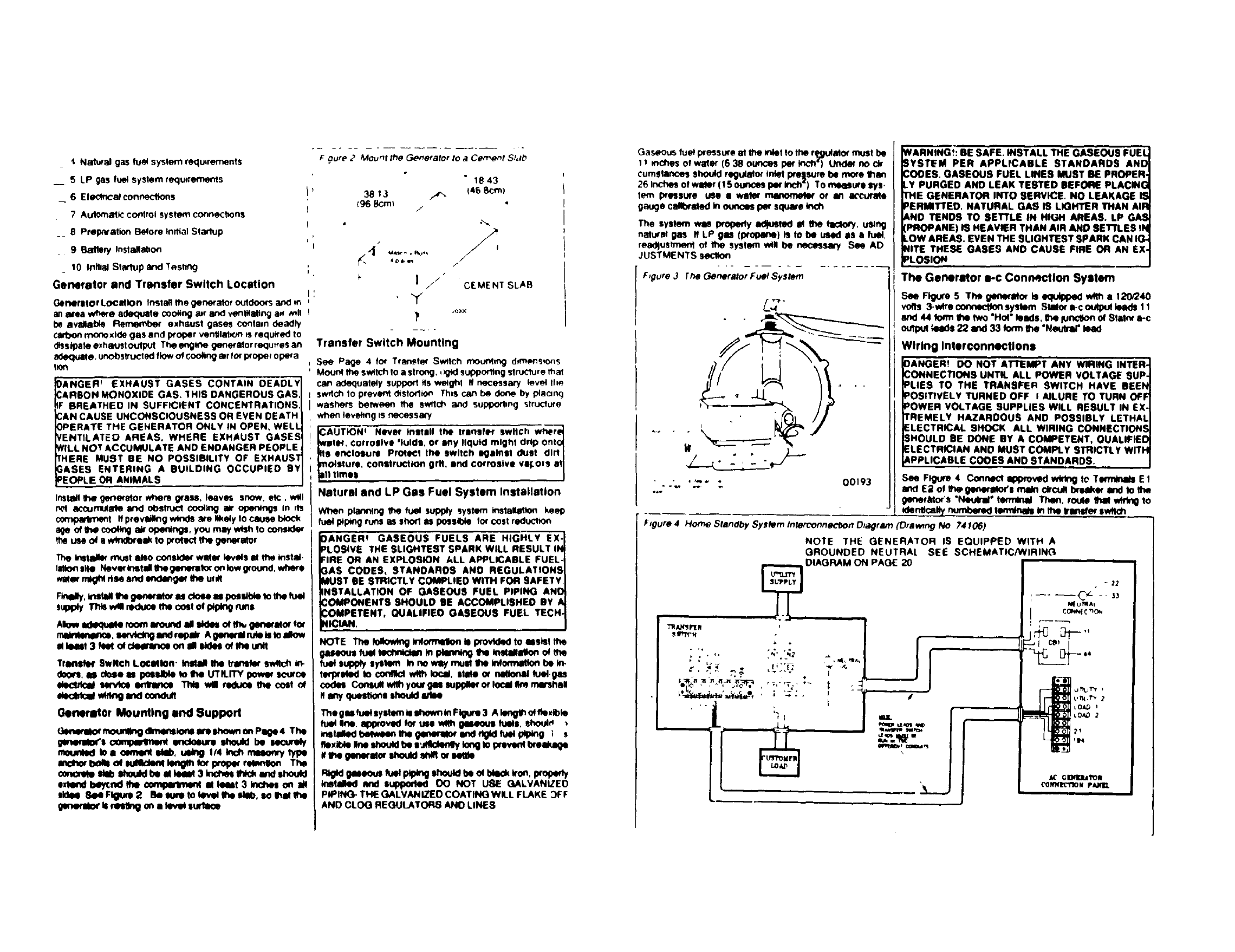
ThegllJ fuelsyatemIsIhown mFigure3 A I_ of It_dble
fuel Ins. approv_l for uN w_h ges4mushJats,shoui_ ,
mteitedl_m_e_tt_g_e_lor_nd_l_lfu_l_V_g 1s
nexi_ I_e shoed _s,.,_le_ey lo_i to prsve_ I_e._0e
it e_e genoroto_ sheuld sNfl o_satlle
Rind gASeOUSfuotp_p_ng0houndbe mbteck_on, i_'otD_'ty
InstekKI lind eup_ O0 NOT USIE GALVANIZED
PIPING. THE GALVANIZED COATING WILL FLAKE _f: F
AND CLOG REGULATORS AND LINES
Gaseous fuel pcessure at the m_eIto lbe r_J_ator must be
_mc_es of wate¢ (6 38 ounces per inch') Under no ck
cum$1ances sh_Jid rear.or inl_ pre,_sureb_ more than
26 Inches of water (15 ounces p_' Inch') To meas_o sys.
tern pressure use •water' mw_x_._lw' or in accurMe
gauge cMlxated in ou_c_s pie square inch
The syatern was property arousal III It_ hlclory, u_ng
nalu_at gas If LP Sm (ptof_lne) _Io b_ U_KI es e fuW,
rea_ustme_1 of 1he system will be necessary See AD
JUSTMENTS seclton
F,gure 3 The Generator Fuel System
WARNING.t: BE SAFE• INSTALL THE GASEOUS FUEL
SYSTEM PER APPLICABLE STANDARDS AND
_OOES. GASEOUS FUEL LINES MUST BE PROPER-
LY PURGED AND LEAK TESTED SEFORE PLACING
THE GENERATOR INTO SERVICE. NO LEAKAGE IS
PERMITTED. NATURAL GAS IS LIGHTER THAN AIR
&NO TENDS TO SETrLE IN HIGH AREAS• LP GAS
[PROPANE) IS HEAVIER THAN AIR AND SETTLES IN
LOW AREAS. EVEN THE SLIGHTEST SPARK CAN IG-
MITE THESE GASES AND CAUSE FIRE OR AN EX-
PLOSION
The Generator _-c Connection System
See FigureS The geneqll_' is equipped_• 120/240
volls 3-w_re_system Slalor _-c ou(pulleads11
and44 fo_mI1_ fwo "Hof"leeds, lie fun_itonof Stalnr_-c
outpul_e-de22 w_d33 Iormt_e "N_utrat"teed
Wiring Interconnectlons
00193
DANGER! DO NOT A1"rEMPT ANY WIRING INTER-
DONNECTIORS UNTIL ALL POWER VOLTAGE SUP.
PLIES TO THE TRANSFER SWITCH HAVE BEEN
POSITIVELY TURNED OFF fALLURE TO TURN OFF
POWER VOLTAGE SUPPLIES WILL RESULT IN EX-
TREMELY HAZARDOUS AND POSSIBLY LETHAL
ELECTRICAL SHOCK ALL WIRING CONNECTIONS
SHOULD BE DONE BY A COMPETENT, QUALIFIED
ELECTRICIAN AND MUST COMPLY STRICTLY WITH
APPLICABLE COOES AND STANDARDS.
See Figure 4 Connect Ippto_KI wM_g IO Tm E 1
and E;I of I_generatofs main circuit brNke_ and to the
garlerg4or's "NeUral" ten_ Tl't_l, route that wtt_g to
td_ntl_m_ numbered temVnats in tt_ trlnt_,_' synch
F_gure 4 Home Standby Systom Interconne_Oon O_agtarn (Drawnng No 74 f06)
NOTE THE GENERATOR IS EQUIPPED WITH A
GROUNDED NEUTRAL SEE SCHEMATIC/WIRING
i/
TI_ANSr[ R
• , h' N2
_'t,_ ,_y_-"_:_, , , _,-,;-,,
eq , • ••
'l
~12
_UntA*
_0_ _

ure 5The Ger+e:atof a c Cor_nect,_n S_ster_
CBI
II,o
l,
2h._
,-- 33_
F,gur# 6 Grounmng the Generator
GROUNDING
LUG
\--.
GnOLJNDING
ROe
,, '_'llg
Conned ire UTILITY power supply lines through a main
hoe orcutt breaker ol proper rating and Io Transter Sw:tch
TeRminals N IN2 and Neutral
Gonn_'t lhe OLISIOm_" LOAD leads trorn the mare dJstnbu
l_n panel fo Iransfer swdch ferrmnals T 1 T2 and Neulral
All _,lecl_cal wlnflg musf be of approved msulabve quahl_es
propedy supported and installed ,n approved condud A
Ile_lbl_ len_ffn ot (-on,'Jud rr,_, be used betw_,en the gene_
alor set and r+gld conduit to prevenl breakage if the genet
alor sh_s or Sallies
The generator set ts equipped wffh a mare orcud breaker
Use ol adequate approved overourrenf profedton ts also
requ,red rathe UTILITY power supply
f AUTION _ The generstor set utilizes an ungrounded_
eulrer' If fhal Neutral IS grounded, Iny shorted con.J
Itfon may result In damage fo the unit For fhatJ
ason. grounding of the Neufral line Is recommendedJ
nfy st the main ele¢lrlcal service enfrar_e j
Grounding the Generator
The Nstlonal Ele_tlc Code requwes the! Hie trarne and ex.
lemal ete,:tn_caly condudive parls of _e gemerator be
wopedy connected to 8n approved earth ground Local
eisctncal codes may also req_e _xoger gro_lmg of the
u_t For Ihst purl_e a groufldk_ tug is pmvlded on lhe
_rst_r comparlme_ Grounding is I_hed by
conneoftng asu_d)le kmg_ of slrend_l _wlra to an
earth etven coppe_ o_ brass rod laledtode) Consu_ a
local electrteJan tot grounding requWements m you_ area
See F_uns 6
Propergrotmdlngw111reduce _poss_ Of alectncal
shock in_ event of • ground fsu_ condltlo_in abeger_
a_morIn connectodele_lttceldevtces Groundlng w¢lMso
halpd4sil_e stalk: ek_Vk_ whk-'.hoftent_Ids u_mun.
grounded equ_meof St_k: _ alone can cause
very _ sho_kend may cause one to believe thst a
sho,rled condltk_ exits inequipment
Control System Interconnectlons
See Figure 4 Control system inle_rconnecttons conglsf of
UTILITY I and 2. LOAD I end 2, and is_cis 23 end t94
ConlrOI systom inle_co_mecflng leads MUST be run m a
conduitthat Is sepum _'o_ the a-c powe_ lead condutl
30;PII$
DANG'I:R 'DO NOT Ar'rEMPT ANY CONTROL LEAD I
CONNECTIONS UNTIL YOU ARE SURE THE BAT.J
TERY CABLES ARE DISCONNECTED IF BATTERY IS_
CONNECTED, THE ENGINE WILL START AS SOONI
ASCONNECTIONSARE COMPLETED SEE BATTERYI
INSTALLATION INSTRUCTIONS J
CAUTION When control system Intarconnectlons are
completed. UTILITY lY_rce power will be dellverecl to
he generator SControl (Logic) circuit board to
)perale a battery frlckle charger This means the hal.
ely cables will be electrically hof as soon IS control
nferconnecflons are complefed, providing the
JTIL ITY power supply to the transfer switch _s furne_
3N TO PREVENT BAI"rERY CABLES FROM BECOM.
NG ELECTRICALLY HOT, DO NOT T'IRN THE
JTILITY POWER SUPPLY ON UNTIL AFTER BA TTER¥
_.AaLES HAVE BEEN PROPERLY CONNECTED
BBtlery Installation
WARNING _ON THE GENERATOR PANEL, BE SUREJ
TO S,.ET THE MANUAL.OFF.AUTO SWITCH TO ITS(
'OFF" POSITION BEFORE CONNECTING THE BAT.|
TERY IF THE SWITCH IS NOT SET TO "OFF", THEI
GENERATOR WILL CRANK AND START AS SOON ASJ
BATTERY CABLES ARE CONNECTED J
Recommend_l is a 12 rolls, automotive lype (Grout) 261
storage barely rated 35 _mphoum or more The balle_
MUST be prop_ly _w_h aleclrolyte fluid end tully
Charged _ to lOsfalhltton _ery Cables were fadory ,n
stalled and c_nected to the g_stor
See F._ure 7 Conne(:1lhe RED bstlery cable fronl fhe en
_O e sfarle_ conlacto( to the l)age_ posf ind_cafed by a
SITIVE POS or (÷) Connecl lhe BLACK cable trom
g_'_ralor' frame ground, to file beltery posf indlcaled by a
NEGATIVE NEe o_ ( ) Cable connections must he
CLEAN and TIGHT
NOTE When the UTILITY power suppty to the IransI_'
switch ,s fumed ON bene_ will recede a trtclde c_arge
from thst powe_ source The trtckkl cherger vvgl NOT
recharge adischetgeU b_ery During enf, ne operst_n
the bllflery W_I recede I ct_rglng cun'enf from the garter
stors batte_ ch_ge cl_cuR
F'_gure * BJtl_Pf Ca_/e Coorle_'f/on$
_r. START[ R c.ONI"A(" ?OR
e_fRv '
BATTERY
.,Y
00219
Post Installation Inspection
Pnor to in,at ';faR'Up_ tosting Of Itm home sfandby sys
tern. mspecl _e entk'e Instelaton cereluby Make sure fhe
unif has been prowly instilled, in accord_lce with ap'
I_Cal_e codes and sl_ndetds Revt_w 1he instalMflon in.
sit uclm_s end Informalk_ in IP_SM_mual a_l make sure all
recommendalions hew) be(m con_ wflh Also review
appllcabie standards booklofs Io ensure thaf those staR._
ards haw _ _ w_h Some are ie may requxe
the1 the Installation be Inspected and aWoved by a Io,:.al
building .-._d/or elecldcel InSpector
POST INSTALI'ATION TESTS
General
The home ";tandby ge_ecMor was fa('lo_ lester:l and ad
lustnd using natt_rsI g_ as a fuel and shoutd req_Jire no
addihnnal a_lustnN)nt t'OWever sp_'tW orcumstances
,';u('h as ct_ar'K_leOvet fo LP gas )wall require some minor ad
jsfn_ent
._;AUTfON; DO NOT wske any unnecessary edlUst -]
'naRiS Flclory eeltJngs Its correct for roDS1 lp_llca- I
Ions Adjuslments Ihoufd be aNempted only by a_
:luallfied generator service fechnK;len ._j
3ANGEfl _USE CARE NOT TO O_ERSPEED THE EN-
3INE DURING ANY ADJUSTMENT EXCESSIVELY
qlGH OPERATING SPEEDS ARE DANGEROUS AND
MAY RESULT IN PERSONAL INJURY OR DAMAGE TO
EOUIPMENT AND OR PROPERTY THE GENERATOR
WILL SUPPLY CORRECT RATED FREQUENCY AND
_/OLTAGE ONLY AT THE PROPER RATED SPEED
SOME ELt_CTRICAL DEVICES MAY BE DAMAGED BY
INCORRECT FREQUENCY AND OR VOLTAGE
Preparation Before Initial Startup
Prior fo tnd,al _fatlup and testing make sure the home
_tan_y _ySiPrt) ha_ been I_opefly msfalted and mlercon
n_cl_,d _oe P()ST INSTAL[ ATtON INSP_ CTION on tt_s
paq-
Atlpt n v,=rv t/+,'.ou()h 13_1 m'_tRNabon nSpectlon has been
(ompleled arid all d,screpanoes Corrected pr,epare the
,_¥51_nl for u_e as tr)_ows
I0,; Ih_ _nera+,-_,r panel set fhe Manua_ CHt Aulo swflch
1,3('31 _10OSlJlOn
2Make _t_re the IITII ITV pow_=r _,,)pply Io the transfer
_wtlrh h'l_ beon posl_velv turned OFt using wherever
meFim; _ov:ded _suL"h a'_ thr, I.ITILITY mare hn_ O_cult
breRker I
(. h_,ck engine crankcase OI1level ff ne('ps_,ar,f add the
rot _,mmend_,d o_lin fhe d,p_h('k F t I[ im_,'k onl_
I
NOTE DO NOT OVERFILl. ABOVE FULL MARK S_
MAINTENANCE sedan for oll level che_k and fltl proce
idures The engine crankcJBe was fl#ed wffh fhe recom
mended o_1_ 1o st',pment However tl is fhe respo_.
i sibd_ of the installer fo ensure th_ crankcase oH level ,s
correcl before affemplln_ sfarlup
Any lltempf to crank snd ltlrl fhe engine]
CAUTION,
before It has been properly serviced wflh the re_om-J
mended oll will result In in engine failure Bo_h fhe an-I
gln_ crankcase led the 011 M4keup Tank must beI
_i_ced with oll !
!Fi_ the OIL MAKEUP TANK with the same _ype and
rage of o_ used In the engine crankcase See MAIN
TENANCE secllon BOTH THE ENGINE CRANKCASE
AND THE OIL MAKEUP TANK MUST BE PROPERLY
SE RVICED
I Transfer Switch Manual Operation
1 Check thst fhe generator sManual Off Aulo swflch has
been sef to OFF posllK)n
2 Turn OFF the UTILITY power supply to the trar,_fet
switch using whstever means j_'ovtded (such as fhe
iUT It.ITY SOUrCemain Xne cwcu_ braakefl
I"t Set lhe .qenerstorsmare clrcufl breaker to its OFF or
OPEN po$11_D_
ANGER' FAILURE TO ",U'RN'OFF ALL POWERI
VOLTAGE SUPPLIES TO THE TRANSFER SWITCHI
EFORE ATTEMPTING MANUAL OPERATION WlL_
ESULT IN E XTREME LY HAZARDOUS AND POSSIB- I
FATAL ELECTRICAL SHOCK j
4 AMANLJAt. TRANSFERHANDLEismIainedaIfhebase
I of fhe transler Swllch enclosure by means of a wing StlKI
=Remove the wing sfud lhen remove the m_nual 1_en_fe_
ihand_
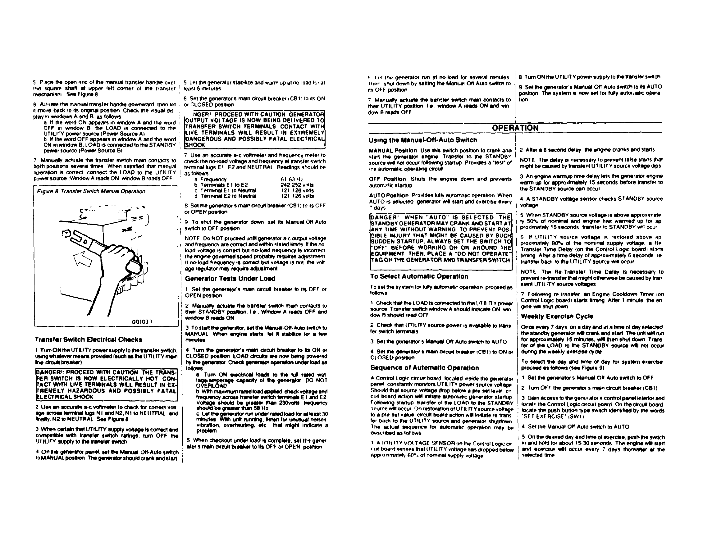
5 P _frle op4m_nd of Ihe manuaJ transfer handle over
the _quam shaft at upper left comer of Ihe transfer
meoranlsm See Figure 8
6 A_t_ml. the manual transfer handle downward lt_n let
move back io _ on_nal pos41on Check the visual dis
play in w_dows Aand B as follows
a If Ifle word ON 81)peMS _nwiodow A alxI the word
OFF on wmdow B the LOAD ;s connected Io the
UTILITY power source (Power So.ca A)
bIfthe word OFF appears m window A and the word
ON m window B, LOAO Is connected to the STANDBY
pow_ so_'ce IPowOr Source BI
7 Manualy achmte the transfer switch main contacts to
both pos_ons several limes When sa1_flad that manual
0pe{alton _s correct connect the LOAD to Ihe UTILITY
power source (Wmdow A reads ON w_dow Breads OFt t
F_gure 8 Transfer Sw_tch Manual Operahon
00103 ]
Tranlfer Swllch Electrical Checks
1 Turn ON 1heUTILITY power supply fo the Iron•far switch.
uslng whatev_' maims provided (luch as 1IN)UTILIT Y main
IRe dlcu_ brelkeq
ANGER,: PROCEED WITH CAUTION THE TRANS- I
BR SMflTCH IS NOW ELECTRICALLY HOT CON-_
ACT W1TH LIVE TERMINALS WILL RESULT IN EX-I
RE.ELY HAZAROOUS AND POSSIBLY FATALI
LECTRICAL SHOCK , _J
2 Use an so_ufatq a-c vo_metM 1och4H:kfor terra,.-1volt
se acroas lermtod lug• Nl m_dN2. N ffo NEUTRAL. and
finally, N2 to NEUTRAL See Ftglxe 8
3_Nt_m c_latn _UTILITY sups)iy v_lllge it correct and
comqNlffil:4e wflh _lnllM tWflch rllk_, turn OFF the
UT It.ITY s_y to the tretletM sw_ch
40nrne ganem_ p4n,d. eel _ManuB/Off-Autosvv_cfl
IoMANUALposit•or•_generatorshoutdCrankand stwl
5 Let _e generator slal_ize and warm up al no load for al
! least ,5 mmutes
6 Set the genaretor s main drcuff Ixeaker (CB 11to tfs ON
,or CLOSE D posltkxt
NGE-RtPROCEED WITH CAUTION GENERATORI
IOUTPUT VOLTAGE IS NOW BEING DELIVERED TO]
ITRANSFER SWITCH TERMINALS CONTACT WITH I
ILIVE TERMINALS WILL RESULT IN EXTREMELYl
IOANGEROUS AND POSSIBLY FATAL ELECTRICAL I
pH_OCK ./
7 Use an accurate a-c vet•meter and trequet_cy meter to
check me no-loa_ voftage and frequency at Iransfer sw_lch
fem'_nal lugs E1 E2 and NEUTRAL Reldlngs should b_
as follows
a Frequency 61 63 Hz
b Tem_als E f Io 52 242 252 v,_tfs
cTermmalE1 toNeutral 12f f26volts
d T_mn_al E2 tONeutral 121 !26 volts
8 Set ff'mgerletator's mar c_'cutfbreaker ICBI ) to ds Of: F
or OPE N posffio_
t. 9 TO shut the generator down set its Manual Off Auto
'i sw4chfoOFF po_lflo_
NOTF Do NOT l_'OCeeduntil glmaretor a-C output vollage
., and trequetx,',f are correct and wll_n staled Wr_s ff _ no
•'load voltage is correct but no-load frequency is _o_red
ilIthe er_ _oveme_ speed W_ebty ._qu_asaw#sfm,._
If no-loed ffe<_AJafl_ts CorTe_ but vol_ege IS _the veil
.{ age regulator may require edlu_Ime_
II Generator TeSIB Under Load
II Set the _enscator's _ c_rcufti'xe_er Io its OFF or
OPEN pos_on
2 Manualy actuate the transte¢ swllch main contacts Io
the' STANDBY poallto_, I •, Window A reads OFF and
wmdow Breeqs ON
3 To sial•he generator, seHhe Mw_-Off. Auto swflchto
MANUAL Wh4m etlQlne sfNfl_J, tel RsUIb411zeto_ a few
rfw_as
4 Turn the gene_lor's mere ck'cu_ I_e_er to _ON et
CLOSED _LOAD d_ults Ira nowbemgpowared
bythe genemlor Checkgen_ato_oF_attonund_ k)adas
folows
a Turn ON _toads to '_e 'n_ _Med w_f
lag@era_| _ cspec_, of t • IBmraid DO NO1
OVERL( tAD
b Wl_rmlxlmumratedload_N)kd checkv_age and
frequency_oss transfarswllch tewnmds Et =ndE2
v_we sh_kl be gre_ar _23erDa _Hlue_y
shouMbe greate_than S_HX
CLet the ganaralor nJnund_r ratedloadfor atleasf 30
minutes _u_ ninny. Ilelen f_ uousuel no_ses
vll_atton, overheating, i1¢ that ml_ Indicate I
prol_em
5 When checkout u_le_ load ts complate, NI th_ ge_er
ator • math ctrcufl_r 1oIts OFF or OPEN Ix_ion
_, I-1 the, generator run et noload f_r several mmutes
Th_,n shut down by seflklQ the Manu,st Off Auto switch fo
_ OF Fposlt_on
7M_nualty adt=m the tran':_ swllch main contacts to
thaw UTILITY posRton. Ia. wlnOow A reads ON arid ,*,in
dew B reads OF F
8 Turn ON the UTIL IT Y power Supply to the transfet switch
9 Set the _m_ratcr's Mir_ual O11Auto swflch to its AUTO
pos#mn The system is now sel for fully auto_,latlc opera
hen
I
OPERATION
Using the Manuel-Off-Auto Switch
MANUAL Po_Iflon Use this switch position to cran_ and
_art the genet_or e_ TrRnSter fo the STANOBv
sou(ca wgl nol OCCurfollowV_ sta_lup ProvKtes a "test"of
,Re automatic ope(almg c_c_
OFF PositiOn Shuts the e_g=ne down and p(events
Butom,_k: statlup
AUTO Poaltlon Provides tully automRh,: operalton Whe_
AUTO _s selected geoeretor will •tell _ exercise every
" _ys
DA_IGER' WHEN "AUTO" IS SELECTED THE
<JTANDBY GENERATOR MAY CRANK AND START A1
ANY TIME WITHOUT WARNING TO PREVENT POS.
_IBLE INJURY THAT MIGHT BF. CAUSED BY SUCI"
UDOEN STARTUP. ALWAYS SET THE SWITCH TC
'OFF" BEFORE WORKING ON OR AROUND THE
EOUIPMENT THEN, PLACE A "DO NOT OPERATE'
fAG ON THE GENERATOR AND TRANSFER SWITCH
To Select Au|omstlc Operation
! o set the system for fuly automat_" o_oera_on proceed as
to#o_s
IChe(:k that _r_e LDAD )s cooP,at:led to the UT h. IT y powe(
soorce Trllnet_'switch_Ashouldkld_wieON vvtn
dow Bshould reed OFF
2 Check _UTILITY sourc_ POWeris avagabte Io trllns
fe_ swilch fmmm/s
3Set the generator SManuIII Off Auto _to AUTO
4 Set the generatu s main ckcuft bre_e_ ICe ! Ifo ON or
Ct OSE D postllon
Sequence of Automatic Operation
A Control to_c c'wcufl board kx;ated _Sk:le the gar_erato_r
p_l constantly monitors UTILITY power so_'ca vol_l_e
Sho_dd that source voltege _op betow aI_e sat level o,
cuff board Icl_n will _Y41ate auto_ generat(x stefl_
Foltowmg stlrhJp franker of 11_ LOA{') to the STANDBY
'_o_'e _oocuf On re•tare•kin of UT ILIT"y source vOYage
to a I_e set villa c_cufl boetd adlort wltl Int#ate re trims
te_ back fo _UTILITY sot_c_ and _Mor sh_tdow_
The acfu_ sequence for _utomH(' opera•mR may be
d_scnt_d as tol_ows
1 A UTIt ITV VOt TAGE SFNSOROn_ Co_'olLo_c*_
ruff board senses that UT IL ITY vndage has (:kolD_d b_low
Rpp, oslr11_Iy 60% Of nomlnlll su_ly volf_e
2 Aftet a 6 second delay the engme cranks and starts
NOIE The delay is necessary to Ixevent telse sta_s IhM
m_lll he caused by transtenl UT ILIr Y source voltage cl_s
3 An entre wwmup t_e delay lets lhe _rato_ _m_ns
warm up for approximately 15 seconds before transte_ to
the STANDBY so_xo_ can occur
4 A STANDBY voltageSanSOrchecksSTANDBY so_J_ce
vo_a_
5 When STANDBY source voffage is Ibove Ipwox_,nlMe
ty 50% of nommal and anme has warmed up for ap
i_oxlmMety 15 seconds transfer to STANDBY w_: ocu_
6 If UTILITY source vofllge is re,_tored 8hove _p
l_OXmmlely 80% of the nominal suply vollae, aH_
Transfet Time Delay Ion the Control Lo_ bom'd_ star_
tmwlg After atime delay of ap_ox_l_a_ety 6seconds re
transfer bac_ to the UTILITY source will Occur
NOTE The Re-Transfer Time Delay IS net:assary to
p(evo_ re-franSfar _mlgttt olf_rwtse be caused by Irar_
s*enl UTILITY source voltages
7Folowmg re lransN_ an Engme Cook:lown Tx1_' fort
Corm'el Lo_c board) staf1_ Itmln_ After I minute the en
gme wVlsh_ dam
Weekly Exerci_ Cycle
Onca every 7 days.on aday and at aIx'Reof dey seter,led
me etandby generatorwglcrank andsfarl The u_ wWn_
for _xlmatety 15 mklutes,wt!lll_m shu_down Trans
fer ot the LOAD Io _STANDBY source wtl not occur
du_g _wetly e_erolse cycle
To _the _ _ time at clayfor systemexercise
proc_d asfollows (see F_gu_e9)
1 Sat the glmerator s Manual Oft Auto switch to OFF
2 "/'urn OFF Ihe _me_llor S m_ c_rcufl I:weaker ICB1 )
3 Gain access lo the g_'_.,,a4or Scontrol _mterto_'
k)cat,, the Control LO_C c_cuq bOard On the ctrc1_lbo_'d
k_ale the push button type sw#ch *CkmtH_d by the words
"SET EXERCISE" ISWt )
4Set the Manual Off AUto switch to AUTO
5 On the deswed day and lime of exercise, push the swffch
mandhoPJ for aboul 15.30 se,,o_ The en_nswil SlMI
I and exercise will occt_ avery 7days ft_matlet at the
6 To shut tt_ gen_rMo¢ donm _the Manual Off Auto
sW_IchIs OFF
NOTE To reset sy,ltem fo, tu!ly _lutomM_ oge_m_on see
TO SELECT AUTOMATIC OPERATION 'Page 171
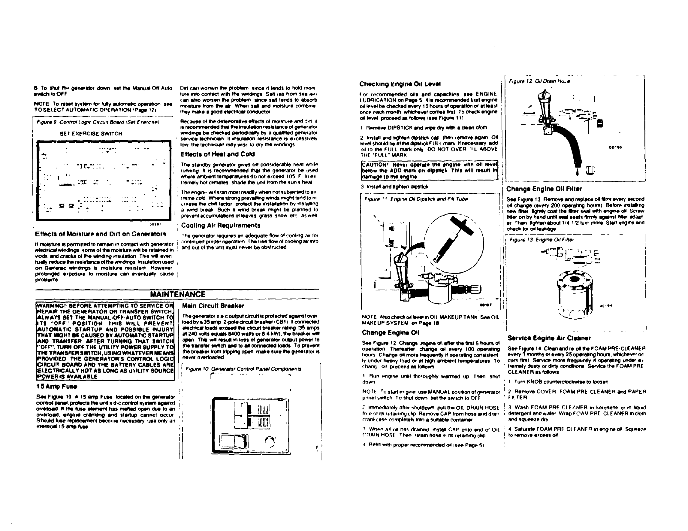
F:_tlv# 9 ContrOl LoI_C Cff_'_JftB_lfd iSOt E,erc,$@!
SET EXERCISE SWITCH
II -- |
&.
4r_
!, * . m, ....
III
307t t
Efflctl of Moisture and Dirt on Generltors
If moisture is l)_m_lt_l to r_ m conllcl_gerN_'ator
e4eclnicalMr_ sore0 of Itw mo_lure willbe retained In
voids and cr_ks o€Ihe winding mulalk_ Th_$ we!even
reduce Ihe resistance _me windings Insulalton used
on Ge_eqlc windings is moisture resistant However
I:.rolonged exposure to ms.lure can evenlually cause
prot4e_e
Ok'1can wOre_en the problem SZnCe 11tends to hold rno_
lure into contllcl wttn Ihe wirings SM ms from sea _t
(an also worsen 1he problem since sail tends to absorb
moisture from _ aK When SM 8rt¢l ms.lure coml_ne
they mJlke agood ek_'1flci__oq
B_:au_e o# the de_eft_iCl_ve effects o#ms.lure and d_1 ,I
Is r_ _the _ul_o_ re_islan<;e o€ ge_r am_
m_l_ be c_K_i(I ixmo_call_by a quill_ g_'_a_o_
' service lechn_ ff _1110_1 re_is|E_ce IS ezC_S$1v_f
low the led_moan may wis, to dry the wmd_$
EfftK:tl of Hell and Cold
The standby gen_Mor gives Off con$_d_ab_ heal w_k_
n.,v,n 9 II is recommended that lhe gene_alo_ be used
where an_mt tempe'mutes do not exceed 105 FI, e.
tremMy ho! dtmlltes shade _Uoit from It_ SU_ $hem
._h_er_n.,_ w111sfa_Inlost relKlily wh_ nolsubtededlo e,
Ir_n_ cold Wilde $ffo_g pe'evBilkng winds roeght lend Is m
cr*ase fhe chill f_1ot I_Oted fhe _r_31Malton by mstWltn_
aw,nd b_eak Such a wind I_elk m_hl be planned Io
p_event_ccumulalfo_ofk_ive$ grass snow el,_ asw_ll
; Cooling Air Requirements
The genera10r requires an adequale flow st ¢ooi_ng air foe
contlnued i:xoper Oge_atk'_ Tbe tree flow of cookng a. _nlo
and out o1the untl m_sl neve_ be ob_truded
i=.
MAINTENANCE
NARNING!' BEFORE ATTEMPTING TO SERVICE on
REPAIR THE GENERATOR OR TRANSFER SWITCH.
&LWAYS SET THE MANUAL-OFF-AUTO SWITCH TO
,TS "OFF" POSITION THIS WILL PREVENT
•UTOMATIC STARTUP AND POSSIBLE INJURY
rltAt MIGHT BE CAUSED BY AUTOMATIC STARTUP
AND TRANSFER AFTER TURNING THAT SWITCH
"OFF'', TURN OFF THE UTILITY POWER SUPPLY TO
rl!_ TRANSFER SWITCH, USING WHATEVER MEANS
PROVtDED THE GENERATOR'S CONTROL LOGIC
CIRCUIT BOARD ANO THE BATTERY CABLES ARE
ELECTRICALLY HOT AS LONG AS U'_ILITY SOURCE
POWER IS A.VAS.ABLE
1 5 Amp FUBe
S4eFl{_re 10 A IS amp Fuse locked on 1he ge_ato_
c<_lto4 penel, ptolecfll Ihe u_l s d-c co_roi Sytlem against
o_doed It Ihe fu_e eCen_nl hem me_ed of_e_ due to an
overlo_d, enghse Ctsnkfr1_ and StStlMp cennot OCCur
Sh0uld _r_ _,i_e necessary _e only an
Idenlcll !S amp _se
Main Circuit Breakar
The generator $ a-c oulput ctrcutl is Wotected agems! ove_
Ioad by a35 amp 21_lecfrcultbreake_lCB1) ifc.xx-.e<-led
elecldcal foad_ exoeed Ihe clrcult b_ellke_ rallng 135 imps
M 240 volts equlN 8&00 wlfls o_ 8 4 kW). 1he breaks' will
"f'h_ wll mlmlt kl Io$$ of gecm_afo_ou_ut _Is
the #ansfet |witch and to all conm)o_l _TOWeven4
me breake_ from _)plng open make sure me g,_rato_ ,$
neve_ oveftoaded
[r_gurero G#n_raforControlPanel Components
Checking Engine Oil Level
f of r_¢ommended 0ill Ind cllpKilit_l IN ENGINE
t UBR;CATION on Plge ,5 # is n_omrneexkKI Umt engtee
ml leve_be che<:kede_;ry I 0houri of Op_'Miofl Or lit 118st
once e_'h monm wf_t_ver corm_ first To check engine
OHlev_4 proceed is tollow_ (m Figure 1 t )
IFkkmove DIPSTICK 111(I wipe dry _• cllan Cfolh
2 In_tMl and l_n d_llk_ cap then remove iIg_n Od
levelshouidbelltlhe0q0_lll_(FUt t rna_ I/nec_ssllry add
0_ to _FULL mark only DO NOT OVER 'l L ABOVE
THE "FULL" MARK
UTION , Never OperMe 111ei_i_ ._
w the ADD mark on dtpvfl¢k TMI will result InI
mlge to tl_l vngme
F_gure 12 Od Dram Ho. •
i
f
00_$$
,SeeF_um _2 Ch_ _ls_ ther_t Shou_ o4
opermlon Therealle_ change oH every 100 ope_al*ng
_y under heavy Io_d o_ al hl_ amb_ml mmp_atums To
_h_nq Oil I_'oceed 115foIfow_
1Hun #ngme unlfl _horou_y wlltmed up Then shut
do,vn
NOTF Tostarl_ng_'w useMANUAL po_onofg_ato_
p_nel 5w_ch To shut Oowtt Sel _switch I0 OF F
2 Imr_:hate#y after shuldow_ puff the OIL ORAIN HOSF
fr_,_=of _t_ tel_nmg Ckp Remove CAP from hose _dra_r
_-r_ni, c_lS_ oomplelely into a Sutlab_e container
"! Wh_ all oil ha_ d_ned install CAP o_1o end of OIL
f';]AIN HOS[? he_ retain hose m Ils retaining
,s Refill w_th proper reco_ Oil Isee Page 5i
Service Engine Air Cleaner
See Figure 14 Clean ind re.oil 1he F DAM PRE-CL E ANE R
eve_ 3 mooffls or ev_'y 2 5 olp_'atlr_ l'murs, whicbev_r o_
Ct_S first _nlo_e frlKIUedllly I! Ot_l_ng _e.
tremely dusty ot dk'_f Com_qk:_S Seneca the FOAM PRE
CLEANER I11 t01fows
t Turn KNOB counlefdockw_e Is loosen
2 Remove COVER FOAM PRE CLEANER Ind PAPER
fILTER
3 Wash FOAM PRE Ct E_INER in kerosene or m IKiu,5
dete_ge_d and water Wrap FOAM PRE CLEANER inCfolh
en_ squeeze
4 SaturMe FOAM PRE CL EANE R ,n _,ne OH Sqt_Peze
I0 remove exce_s OH
NOTE AtsocheckodlevellnOILMAKEUPTANK SeeOIL
MAKEUPSYSTEM OctPllge t8
Change Engine OIl
5 InStMI FOAM PRE CL [ ANER _to _OVE R tollow_l hv
PAPERFILTER TaOsonslOeofPAPERrlI TFRmuqtlock
_qtO SlOIS Of COVER
I_stall _ clea_r a'_r_v ,_ reign with KNOB
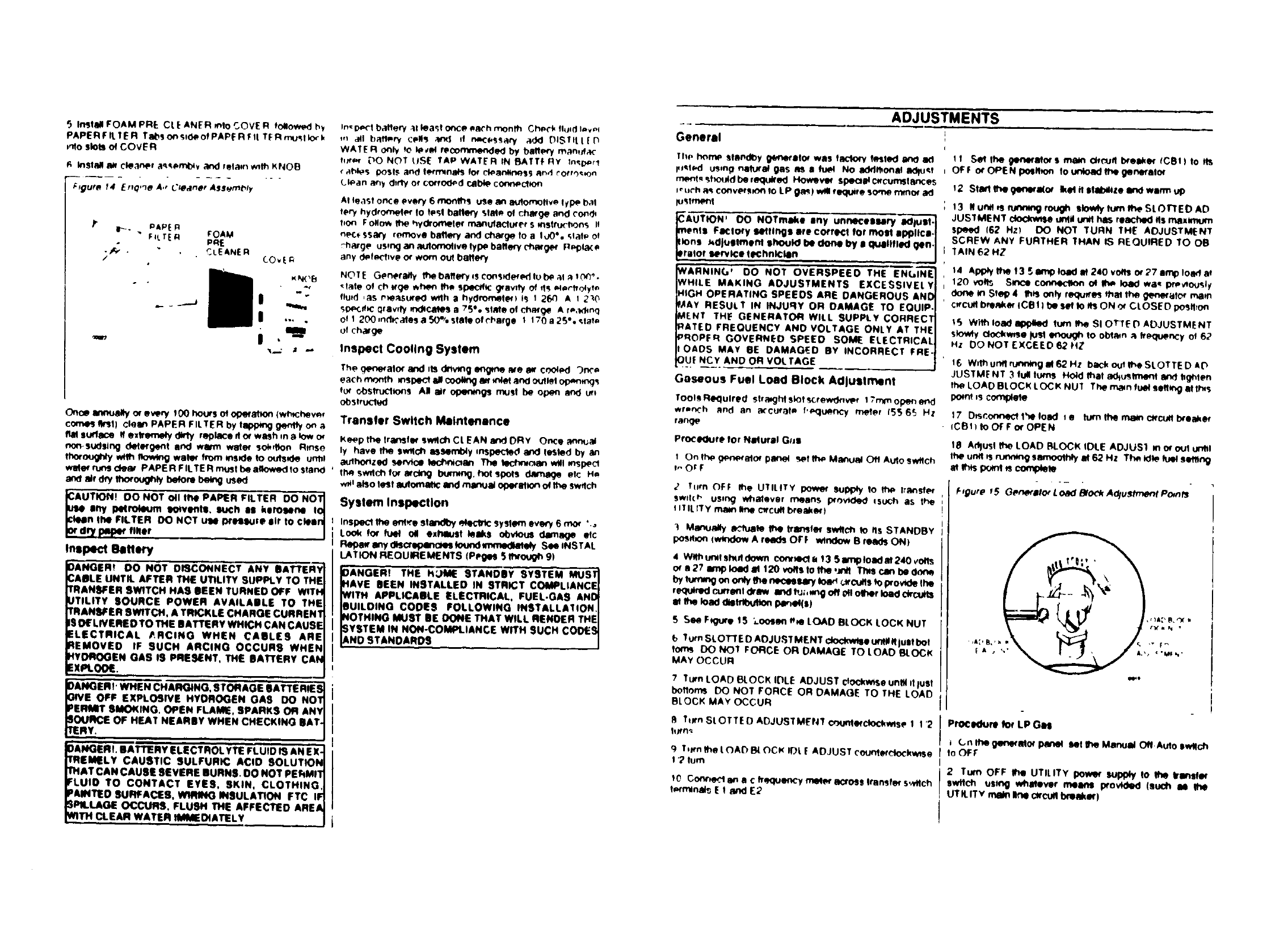
/:laura f4 ErtQ,'_O A,, C'/oelner AseemOty
I'_- PAF'_ R
F4LT[ iCl fOAM
PRE
.jr,_ . _LE ANE Pl
/
I,
i.
In':l_'l batlePf ;11leagl otl_e ea('h month Ch@('k Tl@*dImvol
t,_ _1 bafl_.ry c_d4s a_r_l if m.c_ssary ._dd DIS/Itt[l_
WATER O_IV to ¥.€ol recomt/N!_de(I by baf1_ mane.4.1c
tl_r_r 00 NOT IISE TAP WATER IN BATTF RY tn,_,r!
(,-Ih1_$ 1:_')$15 Rn(I bH'tl_n_ Tot ck_an!it_qs$ and _'O_r,),_n
ATleast once every 8 monlhs use an automotive tyl_' bat
tery hydrom_I_' TOk.,_! ballery st_le of chMge and ('or, d_
fion FOflo_ _ hv_'oCnele¢ rna_ufacIu_r_,r s msTr,.K'Uons If
nP(._SS;b'y remove bMlery and charg_ To aTOO',. _,laT(= O!
rhmge usmganaulomolivelyl:mballe?y('h_'rge_' P_,la(_,
any d,_#_'imve o_ worn OUl bBtle¢_
NOTE Genera_y thebaff_'y=scons_i_'ftub_aTFI;0 _Y',
'Hale O! Chtt_ .h_ the specificg_av_y Of d_ _lSrholyt#
flUid ,aS rq_SUf_O with s hy0f'on_,I_f) iS I_') AI_0
SD_,s/_ _raw Wmd_csdes a 75** sine of cflMge A r_,ldmq
of T200 _nttK',alias a 50% stair of _hllrge 1 T70 a2S°.._lat#
of chaf_
Inspect Cooling System
Once arm_lly or every 100 hours ot oge'almn tw_chev_r
come_ It_Jl) clean PAPER FILTER by l_omg gentty on a
flat surface If e_lreme_y _ly r_l_'e_tor wash ma_v o_
non.sud$1n_ delefgent and warm walet solution Rinse
fexxougtWw_ nowm0 walo¢frommsPO_to outs_Oe un_l
wM_r runs c_ PAPER FTLTE R mus! be allowed TOstand
a_ _,drythoroughlybe_ _ used
UTIOft! DO NOT o11the RAPER FILTER DO NOT]
iiny polro14RJm eotventl, •uIh I• kero•ene Io_
n Ihe FILTER DO N_T Ule IN'ellu_e Itr 10 c)eln_
P/_ finer /
Inspect _ettMy
)ANOERT DO NOT DISCONNECT ANY BATTERY
:ABLE UNTIL. AFTER THE UTILITY SUPPt.Y TO THE
rRANEFER BW_TCH HAS BEEN TURNED OFF WTT_
_JTILITT SOURCE ROWER AVAILABLE TO THE
TRANSFER SWITCH, A TRICKLE CHARGE CURREN1
ISOf LNEREO TO THE BATTERY WHICH CAN CAUSE
ELECTRICAL P,RClNG WHEN CABLES ARE
REMOVED IF SUCH ARCING OCCURS WHEt_
HYDROGEN GAS IS PRESENT, THE EAn'ERY CAt_
EXPt.OO_.
The q_,me_alo,r and _ISdrivmg imbrue _e _ cook-d "_n_e
each month mspe_ all coo_ an' _'_M and oullel op_mmqs
t_ _stn_Iso_s AI ai_ ol>enm_ n_JSI be ope_ _nd u_
_slrocled
DANGERT. BATTERY ELECTROL YTE FLUID IS AN EX-
TREI_ELY CAUSTIC SULFURIC ACID SOLUTION
THAT CAN CAUSE SEVERE BURNS. OO NOT REkMIT
FLUID TO CONTACT EYES, SKIN, CLOTHING,
PAINTED SURFACES, _ INSULATION FTC IF
occums,FLUS. THEAFFECTEDARE
Vg. C eARWATER,mmC,ATEL.V.
Transfer Switch Maintenance
Ke_p the Transl_ s_tlOh CL EAN and DRY Once an_al
ly have _ s_Ich assembly _nspected ancl Tested by an
au_ho_zad sen,_ce tect,_cmn The _roll mSl_Ct
th_ SWltCh for _Rctng I_J_. he! S_<)IS d_ eTc Hm
w_ also lest mu1ott_ll_ and manuJ ope(_ of _Swffch
System Inspection
InsDecl the entre standby _lectttc system ev_y 6 rno_ ".o
Look for rue1 o# extmust leaks oOvlous damage eTC
Ref_' iny cl_or e1_lnol_l 1otJnd m_nedlalely See INSTAL
LATION REQUIREMENTS IPeges 5 thtoggtt 91
)ANGER! THE H:JME STANDBY SYSTEM MUST
_AVE BEEN INSTALLED IN STRICT COMPLIANCE
NITH APPLICABLE ELECTRICAL, FUEL-GAS ANti
BUILDING CODES FOLLOWING INSTALLAITON
_IOTHING MUST BE DONE THAT WILL RENDER THE
SYSTEM IN NON-COMPLIANCE WITH SUCH CODES
ANDSTANDAROS
ADJ'USTMENTS
General
The horrIP Sll_r_d_y ge!letlllof was IRCI_ _sted _ 8(1
_t_l using nelu_al glls m, a _ No addl_ona_ ilequ_!
rrK_T_sh_JId_¢_ Hov_Vtff Spe{:l•lCIfCunlsTatlce$
__r'h_ conversm, n Io LP _! wtll re_jee Some minor ad
_stm_nl
A'U-TION' DO NOTm•ke Iny unnecelllt_ IKII_II- ]
enls FlClory 14Htln_l ere coIre_ for molR •l_llc•-_
ns _djuetment IhouKI be done by • qulllflad qen.J
aTof service ll_hnk:lln . J
WARNTN_' DO NOT OVERSPEED THE ENGINE
WHILE MAKING ADJUSTMENTS EXCESSIVELY
HIGH OPERATING SPEEDS ARE DANGEROUS AND
FAAY RESULT IN INJURY OR OAMAGE TO EQUIP.
MENT TH_ GENERATOR WILL SUPPLY CORRECT
RATED FREQUENCY AND VOLTAGE ONLY AT THE
PROPER GOVERNED SPEED SOME ELECTRICAL
lOADS MAY EE DAMAGED BY INCORRECT ERE-
OUt NCY AND OR VOLTAGE
Gaseous Fuel Load Block Adjuslmenl
TooTsRe_lulred sTfaKJhtsloT_rew_v_r l?mrnop_nend
wr=n('h and an a(curat_,, T'_lu_ncy meter IS[, 65 HZ
range
PrOCedure for NIduril G;_I
1On the _:l_netetor panel _T _ MatvJ_l Off A,._o switch
t_ O r F
Jtl_rn OFF the UTILITY power Sul)lpty to th_ lransfP_
SWlT( t" uEIrl_ whalavar means p_ovl¢led isuch as the
I ITILITy main line cttcufl b_e_kef)
] Ma_u_ly e_uat_ It_ tr_fe_ sw_c_ _ .s STANDBY
poslt_n (wt_dow A re_ls OF F wlnClowB r_ds ON)
4 Wtth_lsh_ldown cor_'l r_13 Swn_toada1240vOtls
or •27 In'_loedM 120vO_slo_0_t Thesc_n be¢:lo?_
by tumm9 on only _e neCe_m Ioa_ _'Cu_s to prov_le The
required cu_erlI draw Ind _J;,mg oli 0!1oltmr load ctr_u_
the load eltnt)ul_ I_l_el(sl
S See Ft_ure 1,5 ',.oos_n ere LOAD BLOCK LOCK NUT
b Tum SLOTT ED ADJUST MENT clock_e u_ll_lust hot
Iom_ DO NOT FORCE OR DAMAQE TO LOAD BLOCK
MAY OCCUR
7Turn LOAD BLOCK IDLE ADJUST ctockwnseuntil dlust
boftoml DO NOT FORCE OR DAMAGE TO THE LOAD
BLOCK MAY OCCUR
1t _the _tne_Mot S mBm Orr_/fl I_'el_' TCBtT to ItS
OF F or OPEN pollt_o_ to unload It_ genefalo_
12 StaLl fit• ge_l_ll(ot Ikel tl slab411ze 8rid warm UP
13 It unit _s_ rough sk_ turn 1he SLOTTED AD
JUSTMENT clo,Ckwtledl_li Undlhas reached gs maximum
speed f62 Hz) DO NOT TURN THe" ADJUSTMENT
SCREW ANY FURTHER THAN iS REQUfl_ED TO OB
TAIN 62 HZ
t4 APF,ly 1he 13 Sim'q_load i_ 2_,Ovofls o_27 amp Toad _
120 _of1_ Since connecl_ ot _ _ wa,_ previously
do_e in STep 4 th_ only requn'_s ms1the generaTOr re.am
c_,cu_Dm_ke_ ICB t Tbe set Io I_ ON o_ C'LOSE Dpostlron
15 Wll_ load I_ turn 1he SI OTTE DADJUSTMENT
sto'_'_ clock'mse Nsl lmough 1o obt_un _#t_u_ncy of 62
Hz DO NOT EXCEED 62 ftZ
16 W_1hunflrunnmgM62Hz backo_eSLOTTEDAD
JUSTM_NT 3 tuli lures Hold thai _K_tut;_t and hghlen
TheLOAD BLOCK LOC KNU'_ The rn_n fuel se.m._It It.s
pOint,Scom131ete
17 DtsconrleCf the Toad le tu,rnttternalnc_cu_tl_reake_
ICBh to Of F or OPEN
18 A_usT ft_ LOAD BLOCK IDLE ADJUS1 m o€ ouI unbl
the un_ Rru_W_g samoolt_y M_2 Hz Th_ Kfle k_1 s_ltng
me_ls pom_m co_
F,gure f5 G@n_.ato_ LDad BlOCk A_lustme_t Po_n_
_J Tmn SLOTTED ADJUSTMENT count_clo_wlse 1 1 '2
htrtl _.
qT_wn'_et OA_BLOCK H')LE ADJUST _'oun1_L"tockw_se
I '?turn
tO Corlned in a C fr_<lUenCY rnete,r aoross Irtznsfe_ S,M%h
ProcK_ure for LP Gi_l
(.,n Theg_n_'_llor p_tel SeTItt_ Manual Ofl.Aulo swllch
1oOF F
2 Turn OFF Iho UTILITY j)ow_ supply to 1tie Iransf_r
Sw_ u_t_'t_ whlltever melns i_ov_ll_d (SUOI1I the
UT K ITv rnal_ line cXcuf110nmkex)

') Miirtuilyllctualefeww._nsf_ ,swdc.hmain ¢ont_ts to
STANDBY IDOSRtonle mndiow A _,_ald_OfF a_d
,mdow B •lids ON
4W1fhunll sty1 €llo_ ¢or,_ect aJbwn'_lo_t 3t 240 voOs
or a _0 Imp _,_ at IZ0 vo.s
5 See Ftguwe15 Looe_ _tOAD 0L _Clf L0(_I_NUT
6Tufft the SLOTTED ADJIJSTN_NT Lad the LOA[_
BLOC'K IDLE ADJUST m Urn! _,ty ate ,;o41tvso_d t')P
NOT OVERTIGHTEN OR LOAD RLOt_K MAY B[.
DAMAGED
70_k OuIIt_SLOTI"FD ADJUSTMENT I t 21urns
9 El_k 0ut tt_ LOAD BLOCK tOLL APJUST 1 2turn
9 S_ N _altoq ,4_•corm br@ake¢,GB I ] l• =Is,._FF
e¢OPEN po_hon SoIt_ ect<_e ,'nay be st_k'_,_,n _, un
co_INmn
10 11Ur_ ts r'u_,_mngro_t_ $Io_ turn I_ SLOT'rED AD
JUSTMENT COurltor_%",ck_e Unt# a_ _o_ural@ ff_lue_ y
meter reads _2 Hz 00 NOT TURN ADJUSTMENT
SCREW ANY FURTHEr_ THAN IS RE. OUIRE D TO OR
TAIN 62 HZ
tl Ai_lytheLOAO _e setff_Qen_atorsmamc,rcurt
_(COt)IoltsON_ CLOSEOpo_tion _Pfope_*n_J_,
m_'e connectod _Stot_4
12 Turn the SLOTTED ADJUSTMENT slowly ck_kw_$e
un#llhe WI_K_m_ mMe_relKIs _?.HZ DONOT EXCEED
62 HZ
13 WIIh_KlU_n_ mele_re_lng62 HZ lumtheSLOTTED
ADJUSTMENT •n eddlltonal ; ' _tums counterdockwtse
Ih_ Ildlu_lme_ _tigt_e_ It_ LOAD BLOCK LOCK
NUT Ttl_ mill tu_diMHltng•1 Ibis poet ,s comp4_te
14 _to•dfromlt_und _e _tlheg_riltmmaln
(_C_II I_'oof_r IO OF FOt OPEN
IS _ _ Ihe LOAD BLOCK IDLE ADJU,ST m m
,x_lumll unll it manlng smooINy al g2 H _ The Kilo fu_ se_
w_g., ml i_nt it om',p_e
Engine Governor Adjust•are
Prww _-c _,qu.my w_d_ d o_ _ .Ul_led a,
t_ec_m_ mglne sp_d. bornt_ f_quw_,_ andme _
NOTE Far noJo_:l _ _n_ _ ct_d_ wo_e
dure. _TRANSFER SWITCH ELECTRICAL CHECKS
IWll_ _m0. st_ down. vitualy Imtp_l ,_e ANTr
t,.ABH61_alNO Make turn Nmn_ b_o_o__d_m'_e0o_
2 LOeeamtheGOVlERNORCt.AMPNUT Pu_ m_0end
_' OOVlERNOR LEVER al S_ wly up I'_Me ol_e STo_te
polglkm) _ho_ Ihe (}OVERNOR LEVER in It_
GOVERNOR SHAFT •nd rotate Ih• _HAFT fully
o0unle_tor_4_ HofdIhest._ in_potl_m m_ ttgh_e_
tt_ GOVERNOR CLAMP NUT to 100 mch-lmun_
,_ta_'t It_ _r_J_ at no Io_l k_ ,t Stat',d_ze ,ln- _1re _,
4 Turn ff_ ADJUST[. R NUT to o_t_ _ fTe_llU_n_"ir_ad,_q
of _t #3 H!
,_mp tO kn_) o_ t22 t_ vOWSlime 10 rmuW._, Ih_ _q_._.
,,_ato_ may req_m_ _llustm_r_
F.ourp f6 Eng/ne GOve_no_Adws_t Po.nts
I
_A
_r-
f
&/_c "V _rI _,_
Voltage Regulolor Adjustment
See Figure 17 W_m e-c frequenr'y IN 61 63 Hz turn fh_
Voft_ I:_ofator SLOTTED ADJUSTER unll v_lage
iTe_N 244 252 yoftl (Ine-to-lmel or 122 t26 vo_t__lme to
rw,_adl
ELI:CTRONIC ,-._-_
I
PROTECTIVE"SYSTEMS AND DEVICES
Gtnlfll
The genes•it• en_ne it equqppedwffh Nv_ml =ys
I_ms'devtceswNOhprotectII mglnsl (•) lowoll levels,(b|
k_ oni_etsur•, end IC)Mg_ o# Nw'4_idum
The ge_rato(s vo.ege I:k,_o_ _o_ora_ o c_cuH
m_ wo_cit Rgin_ m,_. v,_age con_lom
011Makeup Systom
See Fk_ute 18 TheOH _Syltem profec_ theenglr'-
ag_n_t dam_g_n9 low o_ IBve_ tt_ m_t. occur d_pin_
e,tende_ o_e_aeng pe_o_ The t_tem cons_ts of amON
Makm4) TANK In OH MaketAP PRO6E. _nd ON M•k•up
PUMP Ild_lk'N_ W_Pn•_P_'I_'
ol _tssuWIcit_ to _ov_ Ihe #p ofme PROBE. no i. r_
m9 a_lon _41 occur Shoukl 0_level m Ihe cmni_e drop
Im_owthe PRO6E lip. amkca_ vacuum/l_ssure IXdS4n
wll ol3_role I_! PUMP Dur_ PUMP oparlllk_ olfw411be
d_awn from the TANK end d_liv_ed I_ou_ Ihe PROBE
ftpun_llhe PRO_E is ii_li_ sut_mar{/IKlln04 Pump_lc
flon will ttt_ ttop
F_Jre 18 O# MRkeup SysMm
PUMP
TANK
00022 2
6e_ _heON Mei_up Tmk end i_e eng_e cmnkcam mu_
be l_O_edy reed _W_ m_ommended ol Check ol _v_
_ _e ON Idekeup Tmk w_e. engine alnkaRe olI leve4 _
checked flee Pl_e 14) The Tank lind _ engine
c_nnkcase _heu_l he Nled w_h It_es_me tyl_ =_€l grade o_
o11
LOW 011Prelleure Shutdown
The m_glne mounts mLOW ON. PRESSURE SWITCH
IFl_u_e tg) The swltch hits no_mjly ctoded (NC I con
lads wh_h are heKI open by e_y,ne oll pmllure dunng
shuldo,_mwill o_cur
High Temperature Shutdown
SeeFiguref9 The_mounts•HIOHOILTEMPERA
TURE SWITCH _norm4_y-ol_n (N O) contacts
Stem _oiltompemlum e_ ap_oxlmelety 284'
r 1140'G ),lheswtlchc_m_it w111ctosel_i_n•utom_llc
0tt
PIIES._JIII
SWITCH
Overvoltmge Protection
The gerard's i_c oulpul voMge is regu_ed bymsold
state VOLTAGE REGULATOR (Figure 20) This ReguIMm
recedes unmguleted _eme_ng c_xrentfrom the Smt_ Ex
cUllon _ and. _ on "sensing" s_a fm,_ Ihe
Stator lic Po_ w_dlngs, tupples •guided dkecl cur
rentto _ Fk)_xvd_lngs T_s _ypeot rtgule_n •ysWm
it o_en cofleda "voft_e ov_ _mmcy" type. since vo#
iga_il m•lnliNn(idlll •bouI •2-to-1 r8110to freclu_lcy Fo_
exm. M m60 HZ frequency veltage vdll be m_nlined
t20_240 ve_ (,2%)
The Ve_•ge Regu_o_ i equ_ _ an ovar.v_ge
pm_-,t_ clrc_mTt,mmcu_ _1 pm_ectmesy_em m
h_h v_ge #u_gH thin_dmntge Nine c_n@cte_
•l_:t_cll d_,tc_ Iluch _T_Ik VCR't. n,lom_lw_. Mc )
NOTE frl the ev_tl of an ov_.vof_ co_lllfo_, 1tee
Regulato_ wm open the c_cu_ to the Roto¢ wending
_e-celeclnc_louq_ w_ It_ 4raptoneedyzmo
(to a_ll_le equi'ml_l Io m,_lu_l n'_leel_m m I_ I____
I_tt_Mb_t m•_mt_wml Tl_l_ofe¢_lvect_u#it s_.
rB,Jeelng"_U'_I _gener'lor outpu_vo_Oe rm to
as,_B v_lue, n<xm_ a-," OUll_J1wgl relume
NOTE Iflmop4mco_l_. "_€_/rll m _lNmt_
I_lds t I •rK122. fft_ ly_ w 'tMIINllI_4Io (/o tOII "tollIkNd"
condlton Th_ wl mtU# In •n ovar.vol_ge condllto_ an_
subsequer_ toss of R-c OUtl_Ut
Field Boost
See Figure 21 Bane_'yvoRige is itweys •vaiof_ to Ihe
generMo_sConlmlLoglcclmu_lboard,vteIhe t5 amp t_ee
Ou.-g Ha,lup d,'cu_ boardK'lk_ delverz S_ ve_ to
me F_o_ Appkdon of thi_ Fitkl 8oost voltage to It_
Rof_xwtndmgs"Mshes me_ekY _ e_ m_lup 1'1_me.

I_t ensures tt_t an adequale m_nettc Ilekt tsav_k, to
Ixo<lu_ the request "l_CkUp"vottmgem the stator winding*
m ev_t start
F_gure 20 voltage Regulator Inl_t Output Connectmns
m
t
m
J
_| UCrTATW_ Wil_rs_Vj
r gure 2_ F_eld Boost Clrcu_t
I
CONTROL I _-t 4 .--
CIRCUIT 12:'- IS
BOARD
From
Batte_
F*:: o
GiRD _- 4=
_ _T_
ASSE _t_t.Y o_
TROIJBLESHOOTING cHAIIT
SYMPTOM
wncfl III MANUAL
POSSIBLE CAUSES_ +CORRECTIVE ACTION
tBmmtSmml)fU. ! RelmcelSampk_e
mortI crank 2 Loose. d_lyotco_rodedb_ 2 T_N<m, Olu_mtel_mc_cable
cabbs or cmnectkx_
3 We_ ba_e+y
4 Ba4 Manual Off-Autos_l_
50nen o_shortedco_ro__rm
3 I_mOh_'geor_badl_
I
! 4 Rq_baosW_m
No _to STANDBY
UT ILrrY _mu_e twCufe
E_ .Inm mo_ orm_,g _Ah
Iw_Ch II MANUAL or AUTO
Ertgtnt a_. _ll not ttwt
LOW ¢no |-(: ou_
I
6 B_JCo_rol Log_c_oullbo_rd +6 l:1_imbMclrcuNbo_d
IDM_W_elr_'_i_sw_m41 I Te@ml_ceElualk_c_l
20_edl_lrmre_y 2 TmlflmStWro48y
I
_O..._Co_._Lo_. _j__pm_m_.
_ilpmtsu_ ,1SeePoge7
2 Badluellolm_ valve ' 2 Rellllcelmd _
• 30ll;_lorlhofltdWIftll4 _3 Repi_mrNNilc_bld_iIHs)
IOlxeml_acuillxlN_.lCBt ! , IReNi(_)mllnlxNk_
Z O1_m_€_g_Nmm)to voa_t I Z_tecobed _9_e_
30,,e_,o_ge hm_neguJef_
to olxm R," +r ¢Itoull
40_eoll_ Ro_ o* Slal_
5 Sh_l In a cmn_:t_d _oa_
3 I_n uM _t nodoedtm 5 nVr_
4 T_II and nH_e. I_necesm
IS Dl_com_ modled load
I.
THIS PAGE
INTENTIONALLY LEFT
BLANK
ii • i
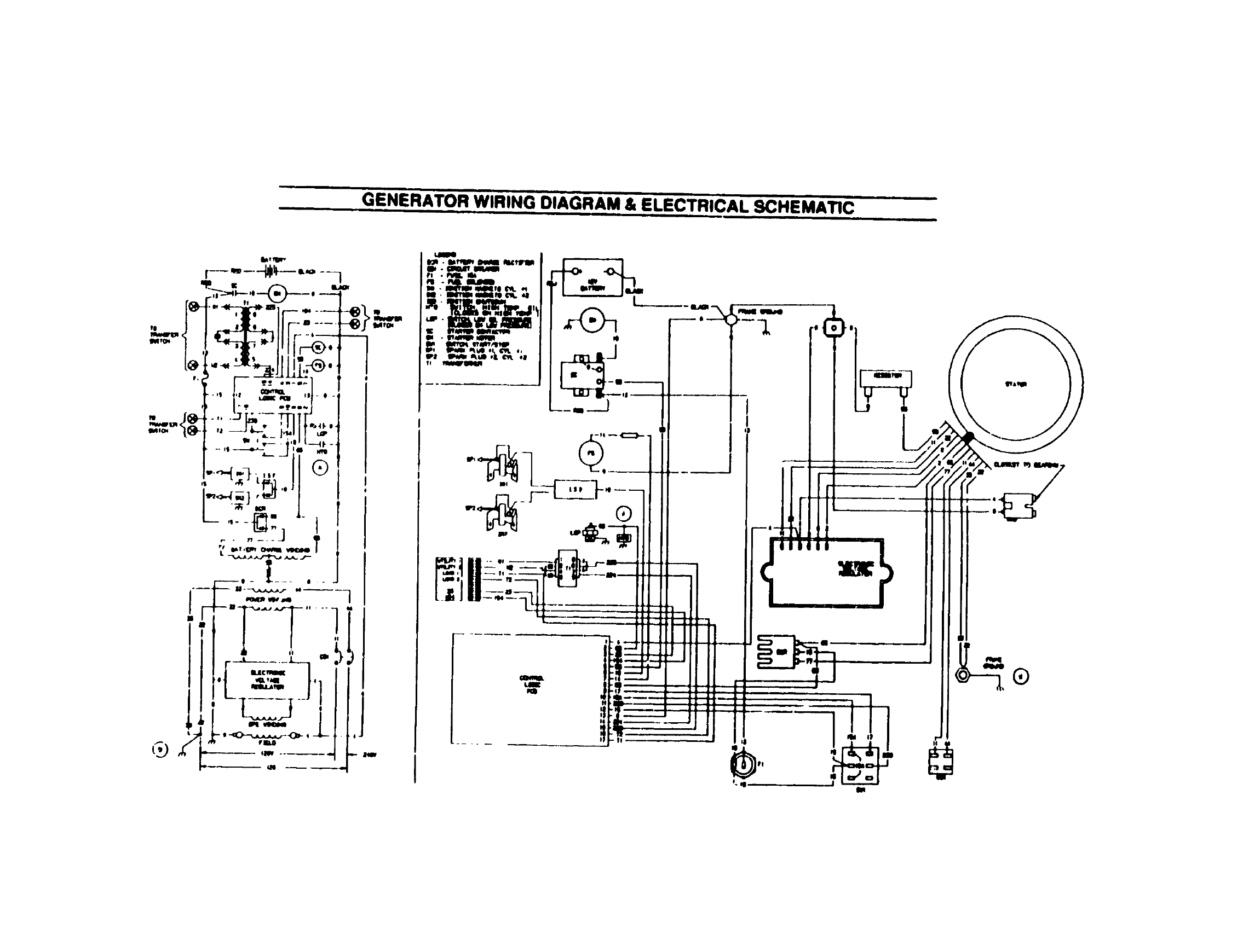
GENERATOR WIRING DIAGRAM & ELECTRICAL SCHEMATIC
ImI I II Hi
I
I_ .fSilISItJI_
____-_':,
T, /

DrawingNo _,ISO_
TRANSFERSWITCI_WIRINg2DIAGRAM& ELECTRICALSCHEMATIC
SCHEMATIC DIAGRAM
N!
WIRING DIAGRAM
,,,I"iL ?
-,i,
l:_!z!z!zlzl',:lzl:JTs
ii i":
N2

REPAIR PARTS ILLUSTRATION- EXPLODE:D VII::W OF GENERATOR
T
"I.___M .
1
2
4
REPAIR PART_ ILLUSTRA', ;ON - EXPLODED VIEW OF TRANSFER SWITUH
4
2
;I
,3
!
PART NO , REO'D ,
(_84g 2
75203 1
74900 i
277S6
?31iF 1
4
P,4dRTNO RlEQ O DESCRIPTION IiTEM
73113 _ROTOR ASSY 10
3_9:'1 * _r.ARING _ Love,
731_tQ # E_.ARIN_ _ U_q_Q, I _1
"7316," ,I STAT(_ ASSY I _2
?23?9 _ C,ARRIER t'_eq Bemm,g
."to146 • STUO Gtm_mar 13
4S77. • NUT He, Me-12S 14
15
\_ qv%%
4 56
19
4)
OIEgC,,IIFTION
x_X_A x._Y l_u,_
S_HEW (Te(_m*l
Ik_ 0 IBOe15m_
CLAMP St_lor Leed
SCREW IT_m)
14e:,-P_ ,_ ,'_,,
WA.q!4E ". ._o_1
NUT F_,m,,_d Lock
Id_-I 2S
.ART.O
-- '* ;'4930'
741)7_ 1
44)t16 3
S22_97 3
6224_3 3
761_1" I
8 27_ t
30gm_7 2
10 _19 2
12 ")IH_ 2
L
' 0f.(ICFIIPTION
_NCCO_mE
COVER Enc#o_re
MECHANIS_ T,*_
100 em_. 2 Pob
CAPSCREW HemF_d
"re-1 O0 _ 12ram
LOCKWA_If.R M_
F1.ATWASHIERM_
RFLAY Trs _fer
12 ve_ d-¢ 101rap
NUT He, _r ,6
SCREW Pan Head
No Ir32 _ _vr
ScREw pw_Head
No Ir32 r !vr
LOCKW_HER N_
Ft.ATWASF_R t_$o
ITEM i
14
15
t6
I?
18
19
20
21
22
23
")4
25
PART NO.ineo'o !
63378 [' 3
..o m2
(14113 i
63_I t
7_2 A2
SI076 4
_t31 i
_4
_e
47_7 I
I
I
Ot[S_IPTtON
•n_ WRAP
LUG- Ne_lr_
SCREW Pe_ Heed
No I0-32 x S,lr
LO_.KWASHER-No i0
sruo.wv,_
_E. T_w_,er
SHIELD
SCREW. Pan la,e_d
M4-O_0 _ 12ram
F'LATWASt._R 3rr
FLATWASF_R. )44
LUO. 8eldmtgt*
DEVt(;E. A_'_t-!_tmlm,
8LCX_. T_mlrml
7.Polillm_
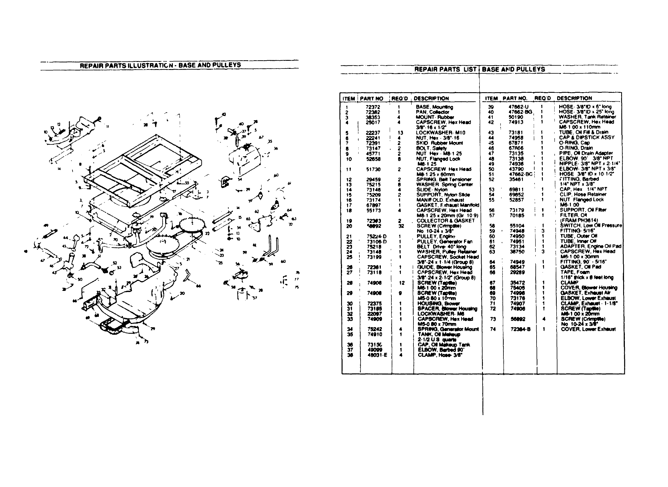
REPAIR PARTS ILLUSTRATIC, N - BASE AND PULLEYS
\
REPAIR PARTS LIST i
ITEMi PARTNO iRSO'OiOESCRIPnON
1 72372 1 BASE, Mo_
72382 1 PAN, Colledot
MOUNT.38353
4g_J017 4 CAPSCREW. He
3_'-16 1 1_2"
65 22237 13 LOCKWASHE R-
22241 NUT. Hex. 3/8 •
772391 2 SKIO Rulbi:w ke
73147 2 BOLT. Slltly
:_7_ 2 NUT Hex •M8-1
IO NUT. FlIIftKI Lc
M6-1 25
11 51730 2 CAPSCREW He
M&I 25 _eOrnm
12 29459 2SPRNqO. _Te
13 75215 8 WASHER .S_
14 73146 4 SLIDE- Nylon
15 7_09 2SUPPORT. N)don Slide
16 73174 I MANIFOLD. ExhlUSl
17 67897 I GASKET E xh,muSlMan4
19 55173 4 CAP,SCREW, He_ Head
M8.1 25x 20mm(Gt I09)
_ _2 COLLECTOR&GASKET
SCREW (Cmnlpue)
No 10-24 x 3/8"
752_4- O PULLEY, E n_k'_,73106-0 11 PUL LE Y. Oenefldo_ F an
7 .,8 1 o,,,,.-4o'lo.o
73140 W)SHER, Puley RMaln_
73199 1 CAP,SCREW, SoOkidHead
34_'.24 _1,114 (Orouq) $)
C_C_EW, He_ He_73119 3/8'-24 x 2-1/2" 1(
74908 12 SCREW (TqMIM)
!46-1 00 x 20mm
749011 SCREW (l'lpIRel
_dS-OSO xlOmm
CAPSCREW. Hex Head
LOCKWASHE R- M1O
NUT, Hex - 3_'. 19
SK_ _MC_m
NUT He. • M8-1 25
NUT. Flanged Lock
CAPSCREW Hex Head
M&I 25 x 60rnm
SPRINO. _Tlmslone_
WASHER _Cenlm
GASKET. ExhauSl Mim#okl
COLLECTOR & GASKET
BASE AHD PULLEYS
ITEM tPART NO. REQ'D ,
39 47662-U I
DESCR_TION
HOSE- 3/0"_), 6" _ng
HOSE- 3_I'ID x 25 long
WASHER. Tank Retaln_
CAPSCREW. Hex Head
M61 00x 110mm
TUBE. ONFill & Drakn
CAP & DIPSTICK ASSY
SCREW (C_lpme)
No 10-24x 3/8"
731_(,
40009
48031.E
PULLEY. (3ene_l_ Fen
3/Ir'.24 x 2.112- (Group 8)
2e scREw _Tq_e)
!46.1 00 x 20mm
29 9
:10 72375 1 _81NG, 8rower
I1 7311111 ! SPACER. _I'_
12 22097 I LOCKWA_IER- Me
13 74909 I CAII>_CRIEW. Hex Heed
MS-O 80 =70ram
14 75242 4 8PRINO, Gimemlor Moun(
15 74910 TANK. (3111_
2-112U 8qU*m
PAP, OI Makeup Tank
ELBOW, Bedx_ _"
CLAMP, Hose.
_2 47662.BG
5O19O
74913
73181
74958
,45 67871
49 07R66
73135
73138
74936 I
43790 I
51 47662-BC
52 3546 I
,_ 69811
6_052
55 52857
5_77 73179
70195
6_ 55104
, 74949
74950
_, , 74951
73134
63 38750
74949
60547
29289
S9 7499e
7317670
71 74907
72 74900
73 50092
74 72384-B
I
4
I
O-RINO. Cap
O-RING, Drain
PIPE. O# Drain Adal_e_
ELB(_, 90" 3/8" NPT
NIPPLE- 3/8" NPT x2.1/4"
EI..8OW- 3/8" NPT x 3/8"
HOSE 3/6" ID x 10- I/2"
rlmNO, ee.,',_
114"NPT x3/8.
CAP, Hex 1/4 NPT
CLIP, Hose Retak_e_
NUT Ranged Lock
IV_I 00
SUPPORT. Oil Fl_er
FILTER, ON
tFRAM PH3_I 4)
SWITCH. Low Oil Pressur_
FrrTING- 5/16"
TUBE, O_er Ol!
TUBE. Inner Ce
ADAPTER. Engine Off PSd
CAPSCREW. Hex Head
M_I 00 x 30mm
FITTING, 90' - 5/16"
GASKET, O11Pad
TAPE, Foe.
1/19" Ihk::kx 8 feet long
CLAMP
COVER, mower Houl_
GASKET, Exheum Ak
ELBOW, Low_' Extumsl
CLAMP. Em_u_ - I- 14_"
SCREW('rq=ee)
M4-1 00 x 20mm
SCREWIC_m_el
NO IO,24 x 3/r
COVER, Lower Exheu_

REPAIR PARTS ILLUSTRATION - HOME STANDBY ENCL-_SURE
L
I
13"
ITEM
1
2
3
4
5
6
7
6
9
I0
11
12
13
REPAIR PARTS LIST - HOME STANDBY ENCLOSURE
REO'D
14
15
16
17
16
Ig
2O
21
22
23
24
25
26
27
28
29
3O
31
32
33
34
3S
36
37
3e
39
4O
41
42
PART NO
I74923"
74924
74922
74925
74926
74927
74996
74926
74931
749e8
74919
74934-A
749e6
75226
23484 F
75211
75212
26916
26307
43768 A
74997
67042
67036
_2108
75407
75411
2823e
28237
75412
75443
22203
220117
22127
22473
22264
Z22_
.'_237
276_
22131
7S413
56414
2
I
1
1
3
3
1
53
2
2
2
2
2
3
3
t
1
1
4
1
' DESCRIPTION
RAIL Lower Front
DOOR ASSY En@osme
RAIL Top Fron!
PANEL. Left S_Oo
COVER. En_osure Top
PANEL. Rew
COVER. Mu!ller 8ox
PANEL Rlg_ S/_de
COVl:R, Batten/Box
ENCLOSURE. Bamm/
FLOOR. Enclc_ure
BOX. Cor_ot
BOX
TRAY _ (Ptaslk:)
BUSHING. S_llp
REGULATOR Gaseou_ f'uel
ADJUSTER Gaseous FuM {Load Block)
NIPPLE Pipe 3_4" x I 3/8"
ELBOW Streel 90" x 3/4"
SOLENOID, Gaseous Fuel
P'UO Cap 2.1_2"dlamefer
tAT(.,: _. RH (#IML)
SCREW r._nHead Mlchlne- NO 8-32x 5/16"
MUFFLER. Ex*'qusl
STRAP. ExhauSl k_,dffM
BOX. Mum_
U.BOLT 1.3/8"
CLAMP. Saddle- 1-3/8" dllmet,;-
ELBOW. Ex_ult TiP
SCREW (_) - 1_4"-20 x 5/8"
CAPSCREW Hex Head - 1/4"-20 x I-1/4"
LOCKWASHER - 1.4"
NUT, Hex - 1"4"-20
FLATWASHE R- 114"
LOCKWASHER - NO II
CAPSCRIEW, Hex Heed- 3_'. 16 x I*
LOCKWASHER - 3/r
BUSHING. Reduom' • 3_" _I/4" NPT
NUT, I,k_x- 341"-16
FLATWASHER - 3/8"
LUG,
LUG. G_ For 2 Ihn_ 8 AWE _

A
REPAIR PARTS ILLUSTRATION - ENGINE ENCLOSURE REPAIR PARTS ILLUSTRA-_C)N --ENGINE ENCLOSURE
-_ _i |xP VIEW
Of CNIIk_TOa
6
13
ITEM PART NO RED D
i ,i
I 1
2
3
4
S
6
?
8
9
10
11
12
13
14
15
16
17
18
19
20
21
22
"3
26
27
28
29
30
^1
.,2
33
34
35
36
37
3e
39
4O
41
87877
67198N
67890
74915
63036
"4904
56892
70520
74903
74918
74_'_08
73190
73189
73186
74902
431/'6
22097
73191
48571
22129
75246
11 47_:_o0
74900
73186
234,84 D
22717.S
22717 A
67066
749_5
74965
22447
40938
48031 E
47662-BB
7495_
42907
48_
06-742_0
09-74260
48031.0
l
i
1
t
1
1
6
1
22
1
I
1
8
[ • ,
DESCRIPTION
EN(_TNF"ASSY (S4HpREPLACE.MENT PARTS
FOR V TWIN ENGINE)
XEY Woodn,'ff 6 x 25
WASHER _llevlfle
NUT Hex M20 1 50
SCREEN AwIrdet
SCREW fCd_)- No 8-32 x 1/4"
HOUSING Ert_ne Top
SCREW (Cr_lteI No 10-32. x 3/8"
MODUI fSho_ng
SCROLL Flywheel
COVER Base #2
SCREWITapUIe) MS x t0mm
WRAPPER No 2 CyNnde(
COVER Valley
WRAPPER No 1Cy#nder
WRAPPER Ball'e_
CAPSCREW He)' Hol_ M_ 1 00 x lOrrlfn
t (3CI"WASHE R M6
COVER Base No 1 C)lhlder
CAPSCREW Hex Read- M8-I 25 x t0mm
LOCKWASHE R M0
SCREWITapffie) 3/8" 18x 1 1/4"
WIRE ASSY No 18
COVER Sml_
WRAPPER. Crl¥1_case
BUSHING Snap
GROMMET- Rul_'_r
GROMM(- r. Rul_
O RING
PROBE. OI! Makeup
RETAINER, O'_M_keu9Probe
WASHER (Shakeproof). M_
SCREW. Sockef _- _ t O0 x 8ram
CLAMP Hole
HOSE. _18" ID
BRACKET. OHM_e_p Pump
CAPSCREW, H_X HeEl - M_-! 2'3 x 1_
PUMP. Off M_
WIRE ASSY (Ground) 5-1/2" long
WIRE ASSY (Qround)- 15" long
CLAMP. Hole
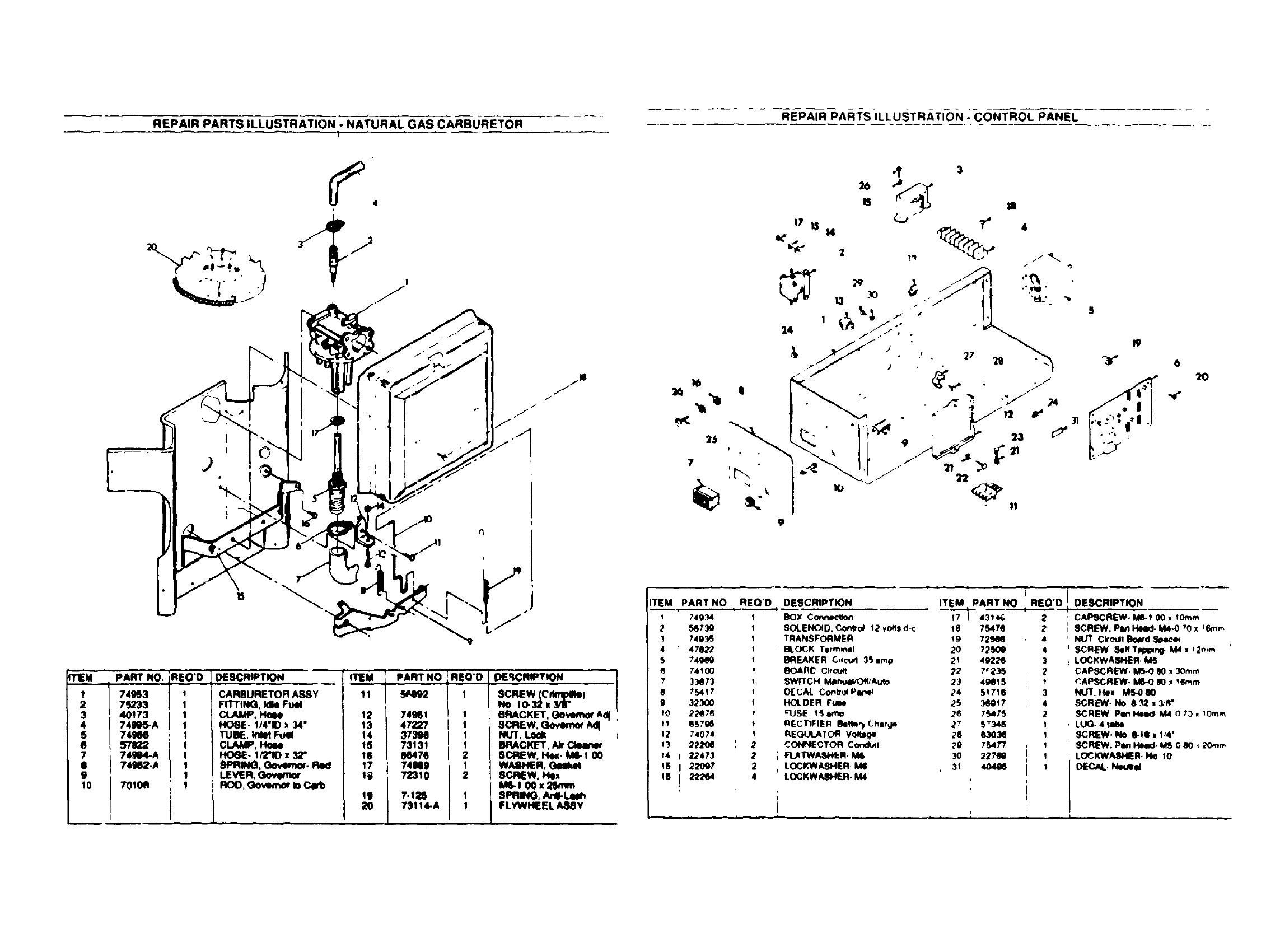
REPAIR PARTS ILLUSTRATION - NATURAL GAS CAR'BURETOR ....... REPAIR PARTS ILLUSTRATION - CONTROL PANEL
3
4
S
6
7
0
9
10
PART7_33749_3NO"iRE:O
40173 !
74995-A
74ge6
571122
74994.A
74962-A
7010A
DESCRIPTION- _PAIql"NO
12 74961
13 47227
14 3739e
IS 73131
IS 06476
17 74919
10 72310
19 7-1_S
20 73114-A
CARBURETOR ASEY
FII"rlNG, Idle Fuel
CLAMP, Hoee
HOSE- 1/4"10x 34"
TUBE, InlelFuel
CLAMP,
_- !/2"10 x 32"
SPRING, Gov*m(x. Red
LEVER, Oowm_r
ROO, Govem_ to Carb
6
_O_'JCRW'TION
No IG32 x 3/8"
1 I _4ACKET, Oowmrto_ AdJ
i
SCREW. (Zo,_m_ Adl
NUT.
BRACKET,/_
SCREW, Hex- ME-1O0
WASHER.
SCREW, Hex
M_-I 0Ox 2Smm
SPRING, Ane-Lmh
FLYWHEELA88Y
ITEM _PART NO REQ'D
t -_
174934
5_739
)7493S
4 4782_
74100
7 33873
8 7_,4!7
g 323OO
;0 22678
12 74074
;1 2220_ :
;4 2247'3
!S 22097
16 222e4
OESCRIPTION ITEM PART NO
BOX Conne_o_ "_43_'_;
SOLENOID. Con_d 1_'vol_ld-c !0 7S47e
TRANSFORMER ;g72_1e
_LOCK Terminal 2'0 7;)_0g
BREAKER C_rcufl3_amp 21 4_22G
BOARC C_cu_ _2 ?_23S
SWITCH M_nmd/O_/A_to 23 4g_15
OECAL Conbol Plmel 24 51716
HOL OE RFtle 2S _{)17
FUSE 1Setup 26 7_75
RECTIFIER Bett_,'y(,hlrge 27 5"345
REGUt.ATOR Vo_ege 28 I_103_
_:ONNECTOR Co_x/_t ;'g 7S4T7
PLATWASHbR. M6 _0 22760
LOCKWA_R M_ 31 404g_
LOCKWAEHER. M4
i
IREQ'D !
2
2
4
3
2
t
3
4
2
1
1
1
1
1
20
i .., ,.
DESCRIPTION
CAPSCREW- ME-_ 00 • t0mm
SCREW. PEnHead- M4.0 _0 x_Em_
NUT C#ou.B_ ,_
SCREW _<lffTl_pmg. M4 x _2*_m
LC(;KWASHER. M_
CAPSCREW. _iN) _ _Omm
_APSCREW. M_O00,16ram
NUT. H_ MS-000
SCREW- No 8.12 _3_8"
SCREW PenHeed, M4 0 70. 10ram
LUG- 4 robe
SCREW. No e-t0 z 114*
SCREW, Pin _MS 0 80 _2Ore.,
LOCKWASH_R. No 10
OECAL.Nw._-_
O
171
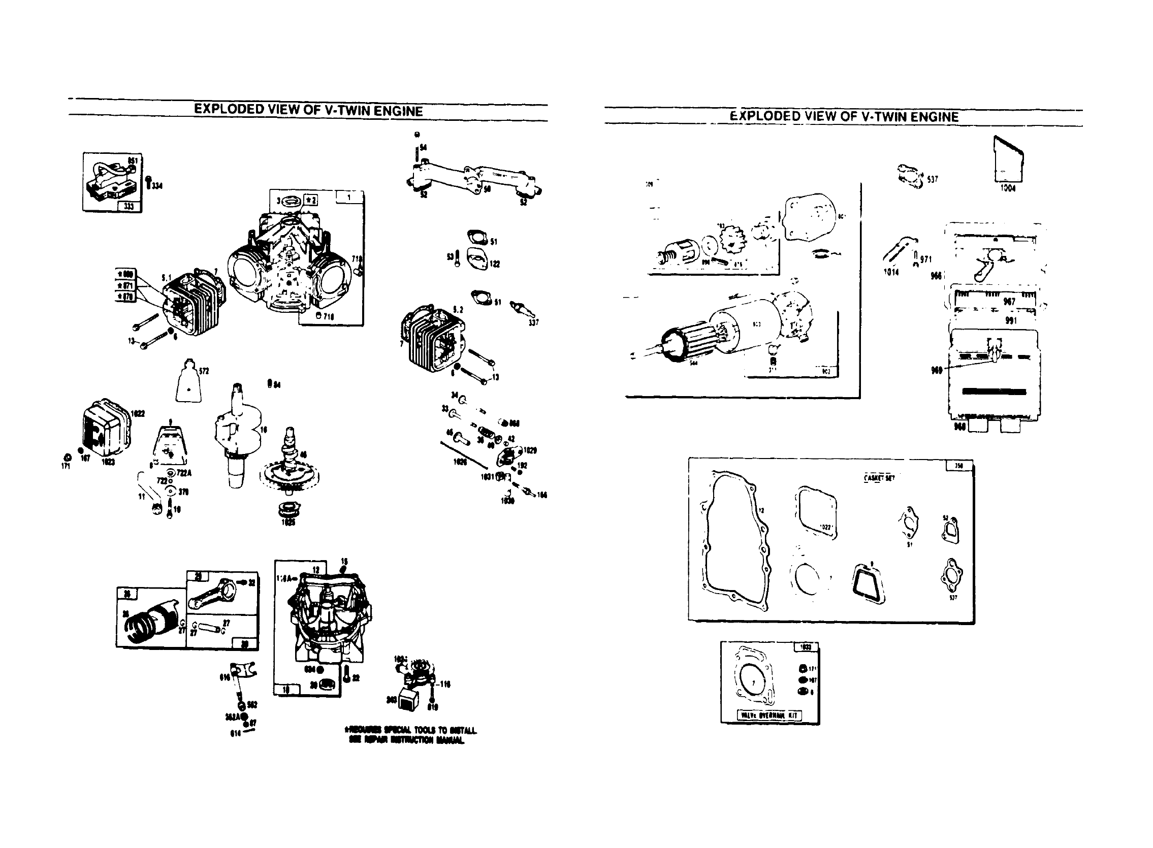
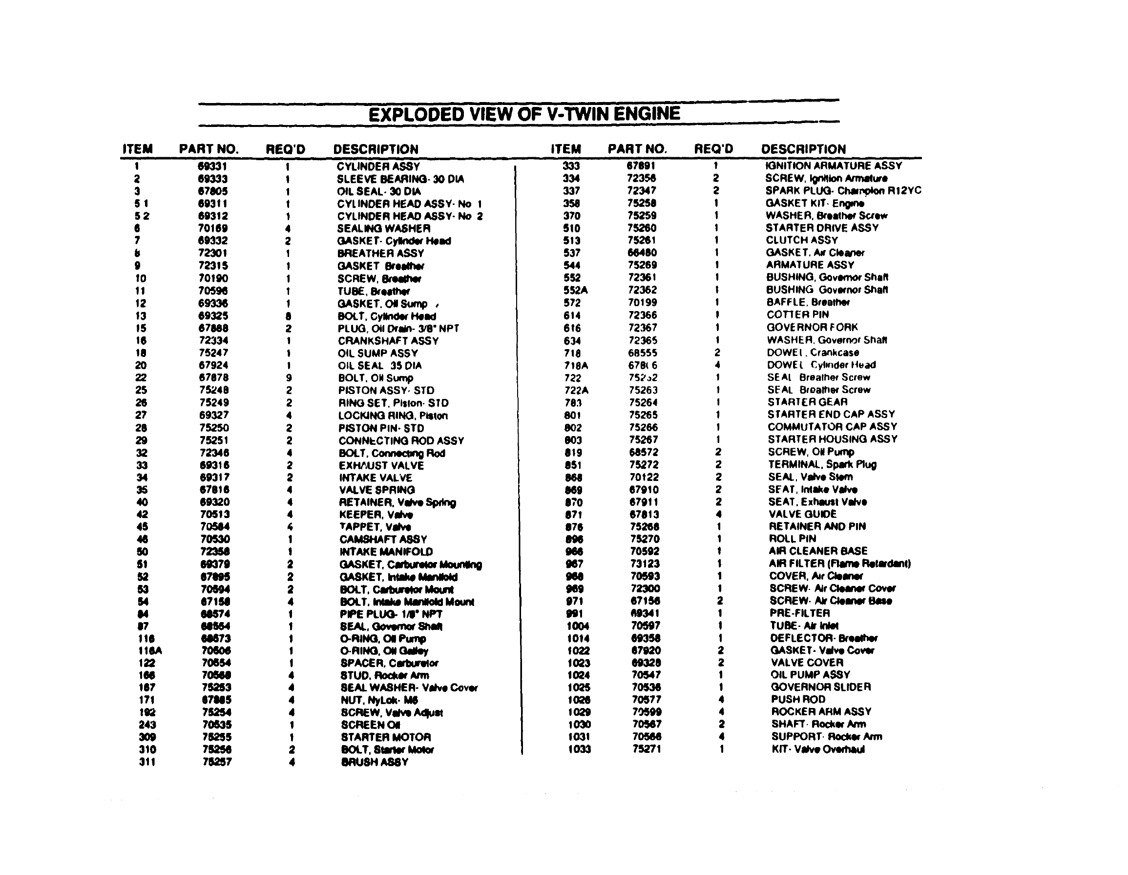
EXPLODED VIEW OF V-TWIN ENGINE EXPLODED VIEW OF V-TWIN ENGINE
!
_", n__"
114"*
o
I"
_u*_. _" m%- 0,1_ ,
N_
,I
,: It
,'F_! o,,,
°"
_4 0o
_T
iII
...... EXPLODE'D-VI'EWOF V-TWIN ENGINE
l n mml • e
ITEM PART NO. REQ'D DESCRIPTION ITEM REQ'D
•Imm
C'VLi ,DERASSy 2
2
I
2
3
51
52
e
7
Is
9
f0
I1
12
13
15
16
19
2O
22
25
26
27
28
29
32
33
34
36
40
42
45
46
SO
51
52
63
I;4
04
07
116
IIBA
122
IN
147
171
192
243
3O9
310
311
69333
67805
693 i I
69312
70159
69332
723O1
72315
70190
7O596
69336
69325
67888
72334
75247
67924
67678
75248
75249
69327
7525O
75251
72346
69316
69317
67916
69320
70513
7O544
7O52O
723U
69379
67895
7O694
0719
05$74
M634
08673
70654
70608
73253
87M5
7S254
/0635
76355
75256
75_7
I
!
I
I
I
4
2
I
I
I
I
I
8
2
I
1
I
9
2
2
4
2
2
4
2
2
4
4
4
,G
I
I
2
2
2
4
!
!
I
!
I
4
4
4
4
I
I
2
4
SLEEVE BEARING- 30 DIA
OIL SEAL- 30 DIA
CYLINDER HEAD ASSY. No I
CYLINDER HEAD ASSY- No 2
SEALING WASHER
GASKE T. Cylkldw Head
BREATHER ASSY
GASKET _reldho'
SCREW, l_'eemer
TUBE, _reltt_r
GASKET. Oil Sump ,
BOLT. Cyllnd_ Head
PLUG, Oil DtrIWl- 3/8" NPT
CRANKSHAFT ASSY
OIL SUMP ASSY
OIL SEAL 35 DIA
BOLT. OH Sump
PISTON ASSY. STO
RIND SET. Plslon. STD
LOCFJNG RING. Piston
PISTON PIN- STD
CONNbCTING ROD ASSY
_XT, Connect_Rod
EXHAUST VALVE
INTAKE VALVE
VALVE SPRING
RETAINER. Vllve
KEEPER. Valve
TAPPET, Vdve
CAMSI_FT A88Y
INTAKE MANIFOLD
GASKET.Cart)ure_ _oun_g
GASKET, InNke
BOLT,Ca_i_nW_Mounl
BOLT, Inmlo Manlold Mourn
PIPE PLUG- 1/11"NPT
8EAL, Oovqmw ShN
O-RING, Oil Pump
O-RING, Oil
SPACER. Cw11_r_or
8TUD. Rocker An.
8EAL WASHER- Vmlve Cevw
NUT,NyLok-M6
SCREW.VWveAdam
SCREEN 04
STARTER MOTOR
BOLT, 81amw Mo_
BRUSH A88Y
PART NO.
333 B7591
334 72356
337 72347
358 75250
370 75259
510 75260
513 75261
537 66480
544 75269
552 72361
552A 72362
572 70199
614 72366
616 72367
634 72365
718 68555
718A 678( 6
722 75;/,)2
722A 75263
783 75264
801 75265
802 75266
803 75267
819 68572
851 75272
868 70122
869 67810
870 67911
871 67813
976 75268
75270
966 70592
967 73123
_e 70593
969 723OO
971 671EB
891 U_II
1004 70597
1014 69358
1022 67920
1023 (HD320
1024 70547
1025 70536
1026 70577
I O29 7_J99
1030 70547
1031 70566
1033 75271
2
2
2
2
2
4
I
1
1
I
1
I
2
1
1
I
2
2
I
1
4
4
2
4
I
DESCRIPTION
IGNITION ARMATURi ASSY
SCREW, Ign41to_AmOur,
SPARK PLUG- Champ4on RI2YC
GASKET KIT- En_
WASHER. Btomth_' Sctow
STARTER ORIVE ASSY
CLUTCH ASSY
GASKET. A_'CIo_
ARMATURE A_Y
BUSHING. OovemO_ Shaft
BUSHING Governor Shaft
BAFFLE. SrnI_
COTIER PIN
GOVERNOR FORK
WASHER. Governor Shaft
DOWEt, Crankcase
DOWEL Cylinder t4e_l
SEAL Breail_er Screw
SEAL B_oalher Screw
STARTER GEAR
STARTER END CAP ASSY
COMMUTATOR CAP ASSY
STARTER HOUSING ASSY
SCREW, Oil Pump
TERMINAL, Spark Plug
SEAL. Valve Stem
SEAT, InUmkeValve
SEAT. Exhaust Valve
VALVE GUIDE
RETAINER AND PIN
ROLL PIN
AIR CLEANER BASE
AIR FILTER (Flame Rolwdanl)
COVER. A_rCleJ_'
SCREW- Air Cleaner Cover
SCREW- Air Cle_ne_ Base
PRE-FILTER
TUBE- Air In_
DEFLECTOR- Bma#_r
GASKET- Valve Covq_
VALVE COVER
OIL PUMP ASSY
O,OVERNOR SLIOE R
PUSH ROD
ROCKER ARM ASSY
SHAFT- Rockw An_
SUPPORT. Roc_qurArm
KIT- Valve Oved_ul
THIS PAGE
INTENTIONALLY LEFT
BLANK THIS PAGE
INTENTIONALLY LEFT
BLANK

THIS PAGE
INTENTIONALLY LEFT
BLANK
THIS PAGE
INTENTIONALLY LEFT
BLANK

THI--3 PAGE
INTENTIONALLY LEFT
BLANK
THIS PAGE
INTENTIONALLY LEFT
BLANK

THIS PAGE
INTENTIONALLY LEFT
BLANK
THIS PAGE
INTENTIONALLY LEFT
BLANK

THIS PAGE
INTENTIONALLY LEFT
BLANK
THIS PAGE
INTENTIONALLY LEFT
BLANK

THIS PAGE
INTENTIONALLY' LEFT
BLANK
THIS PAGE
INTENTIONALLY LEFT
BLANK
