General Dynamics Broand NODEBAMF Base Station User Manual Installation Manual
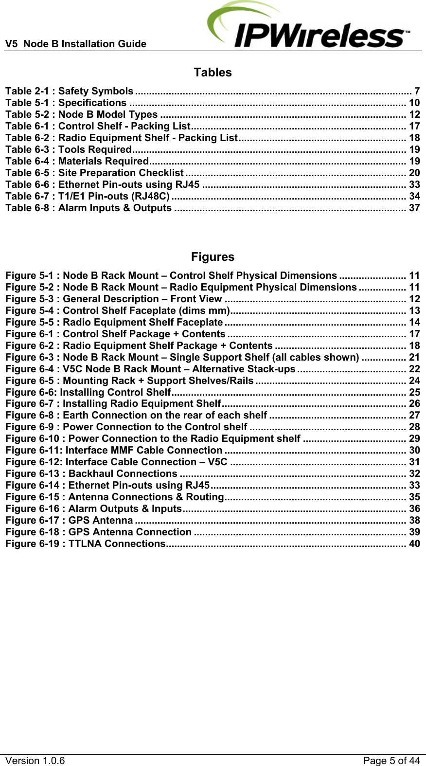
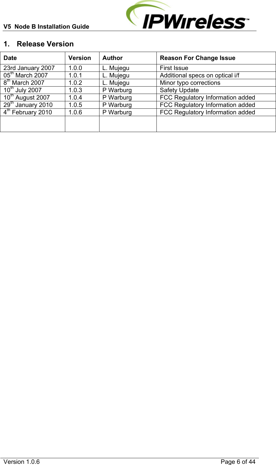
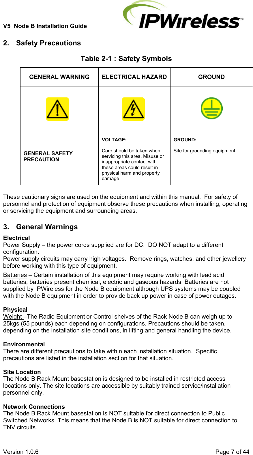
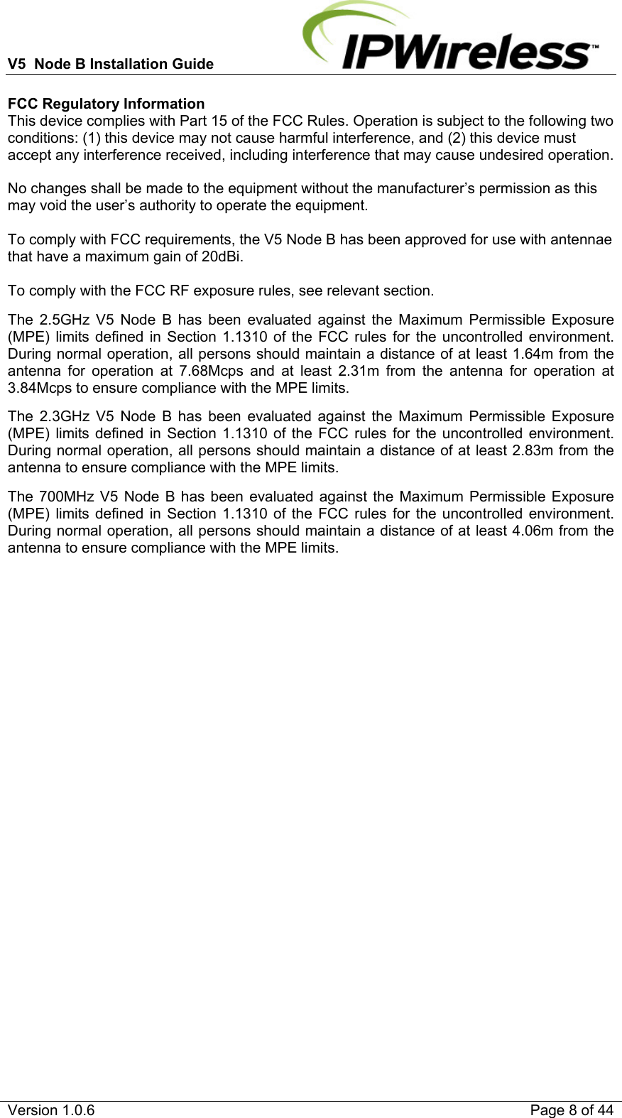
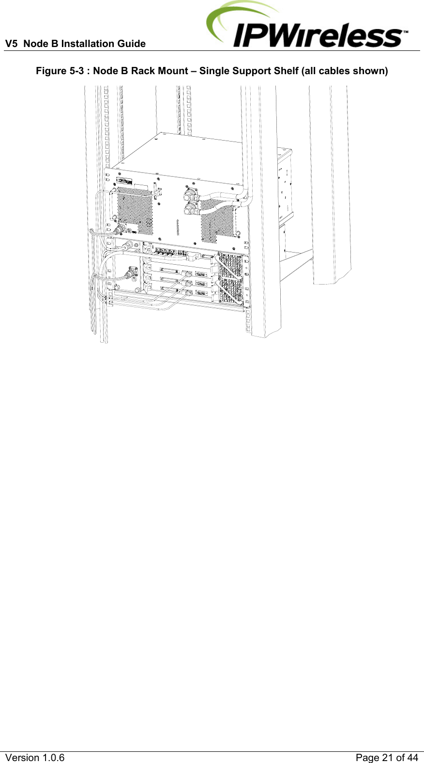
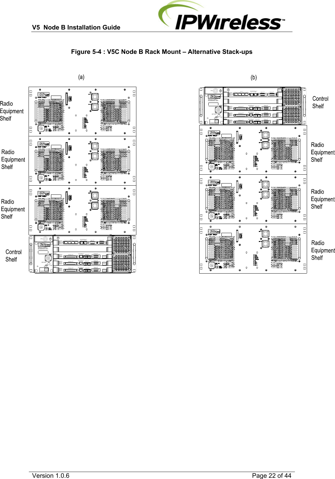
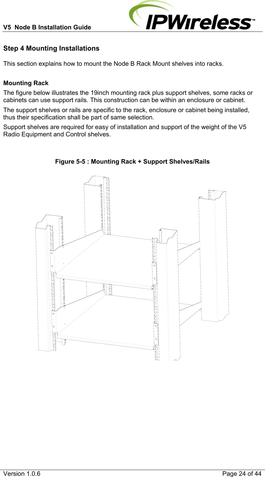
General Dynamics Broadband, Inc. Base Station Installation Manual
UserManual.wiki
>
General Dynamics Broand
>
NODEBAMF User Manual
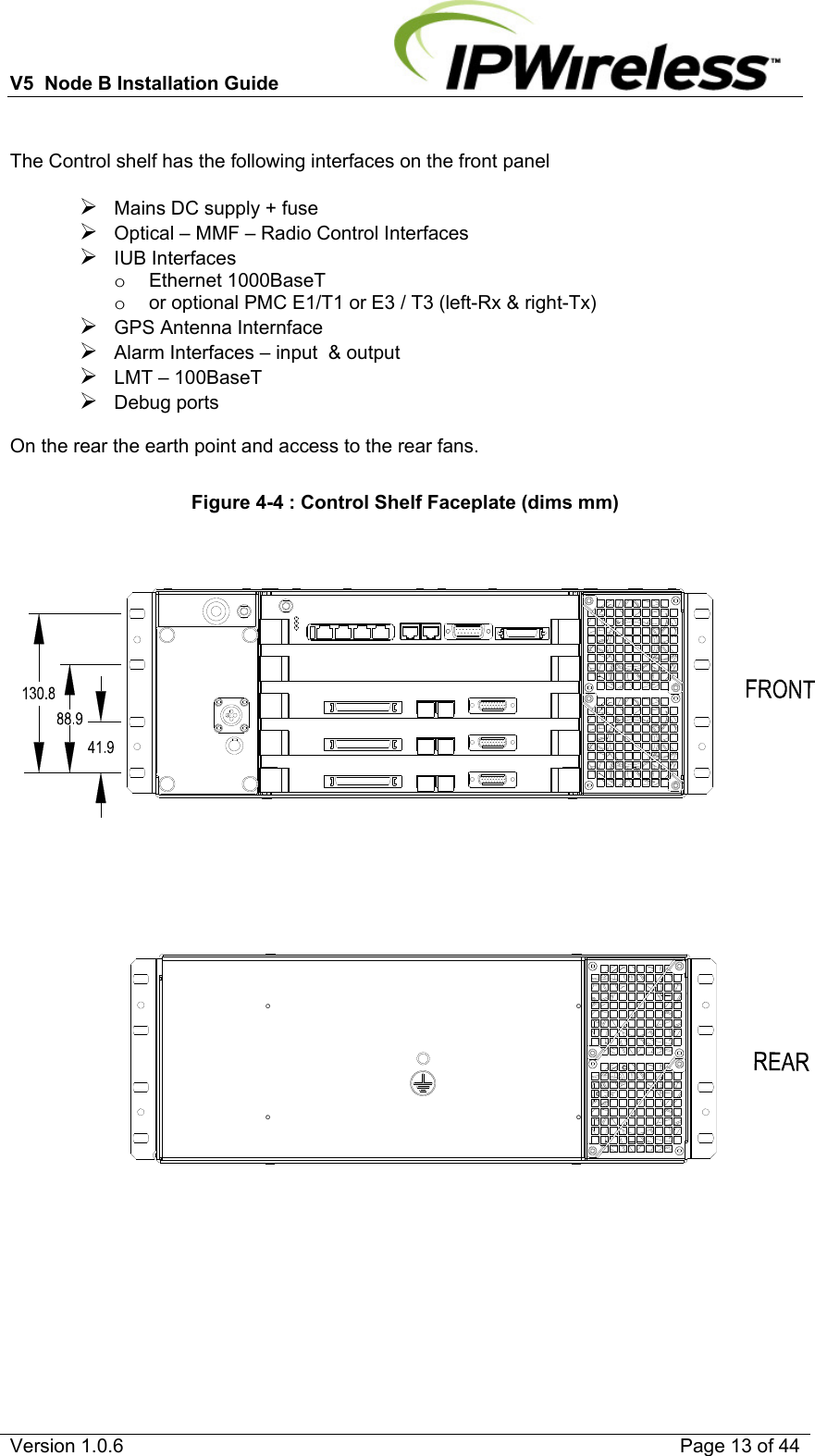
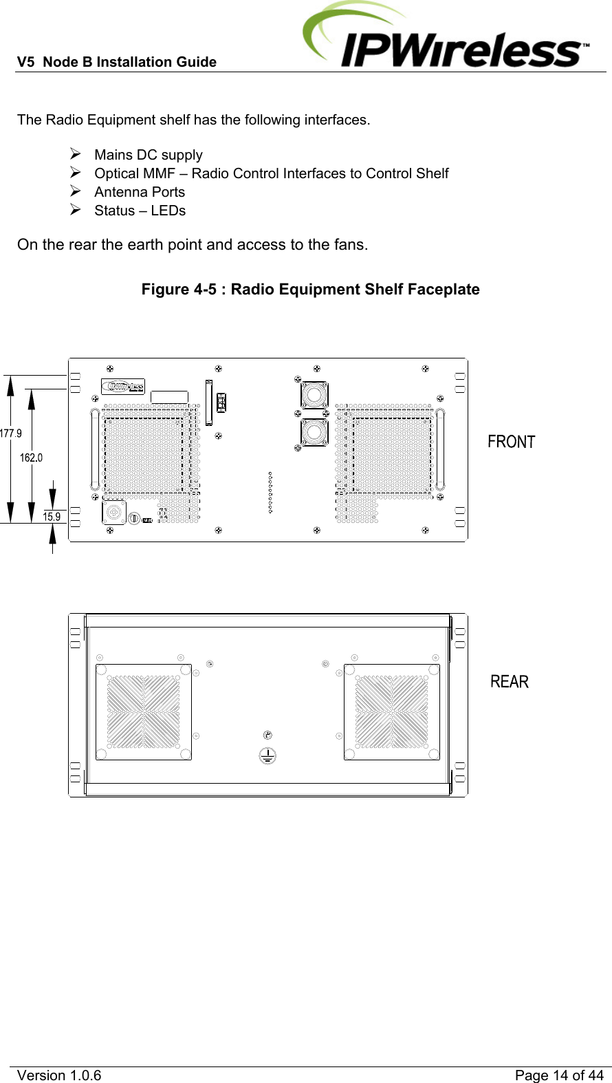
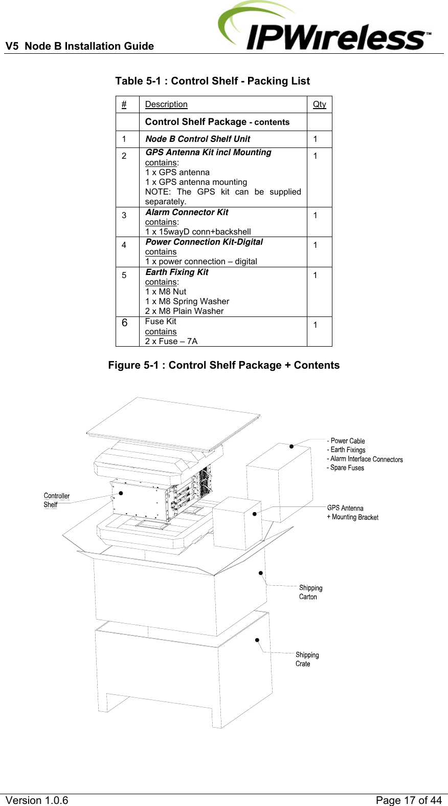
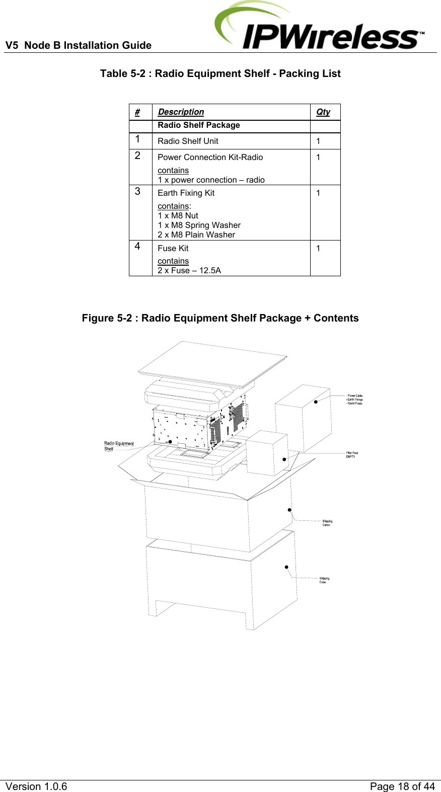
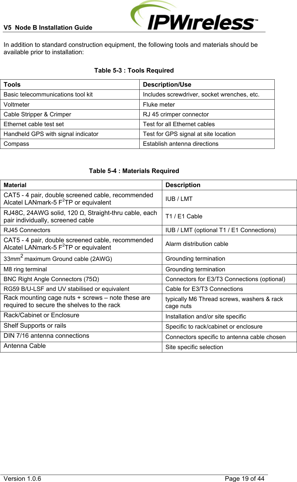
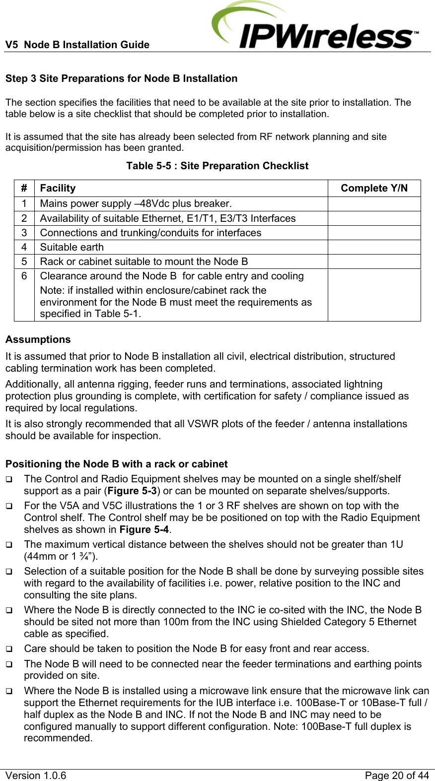
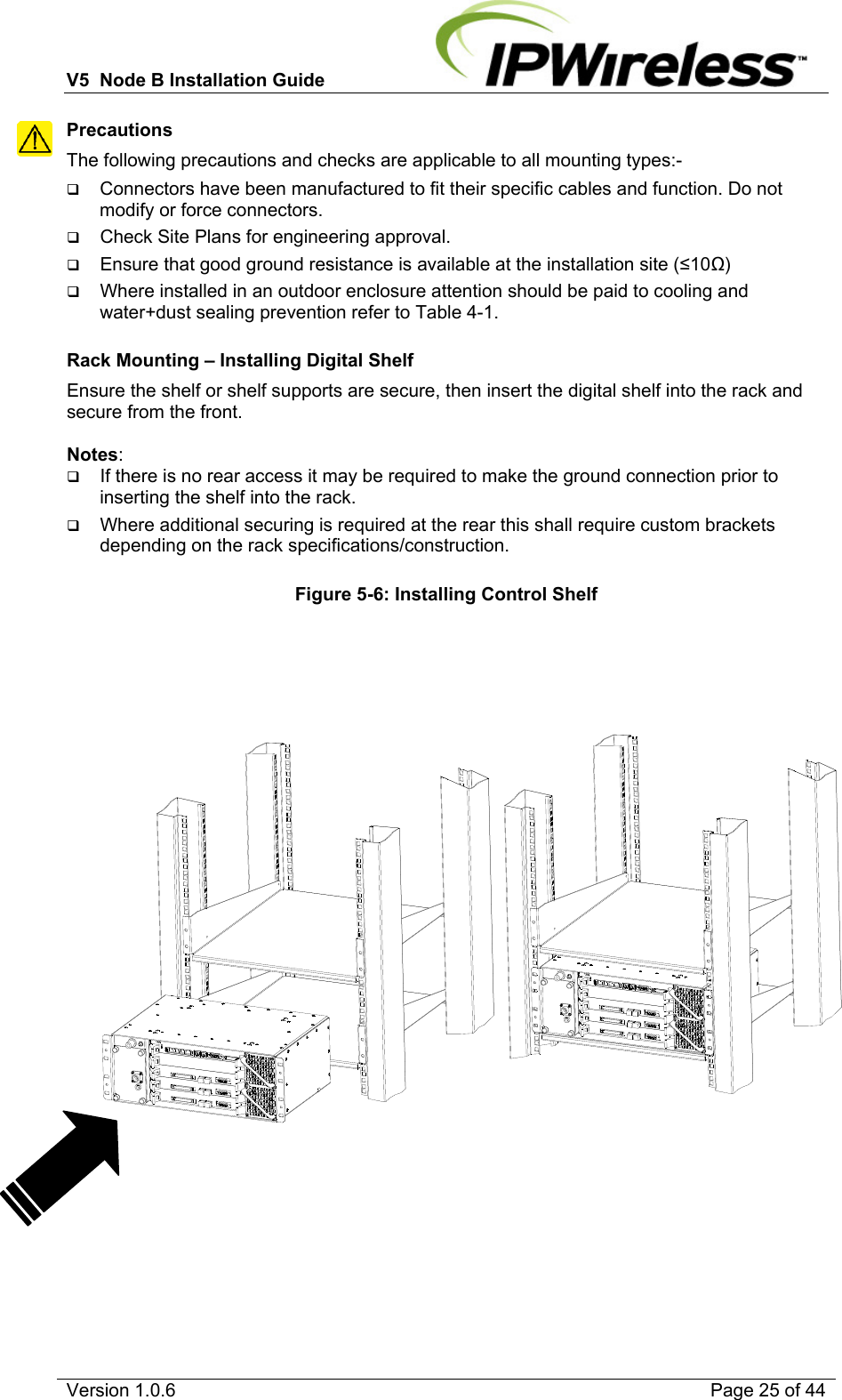
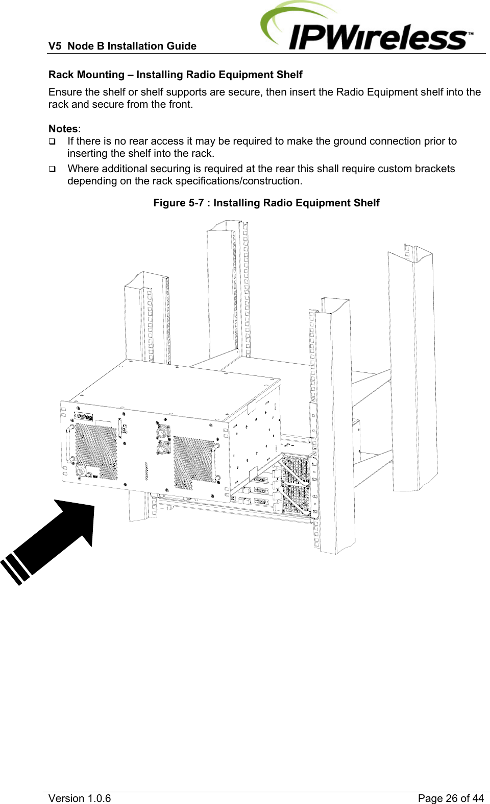
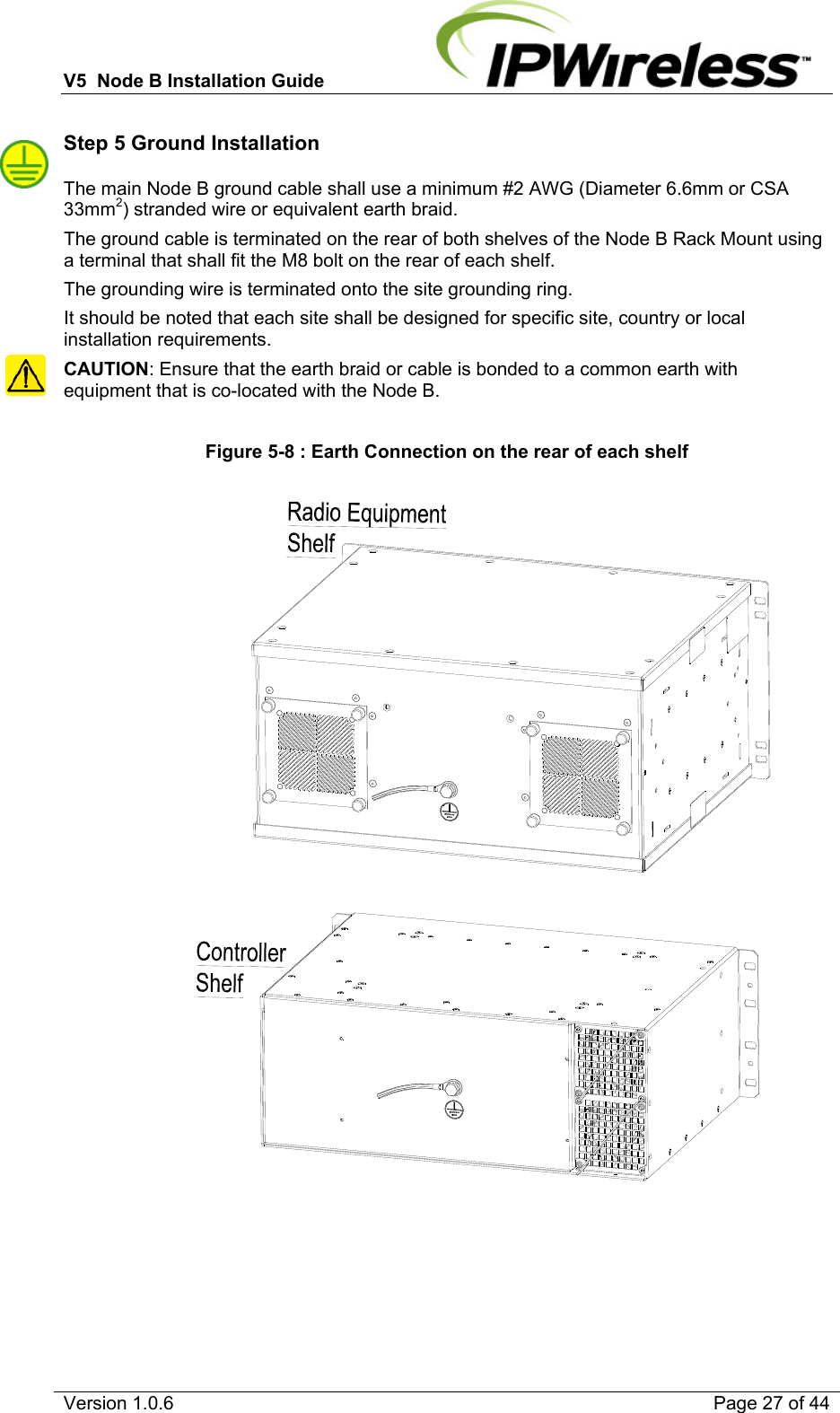
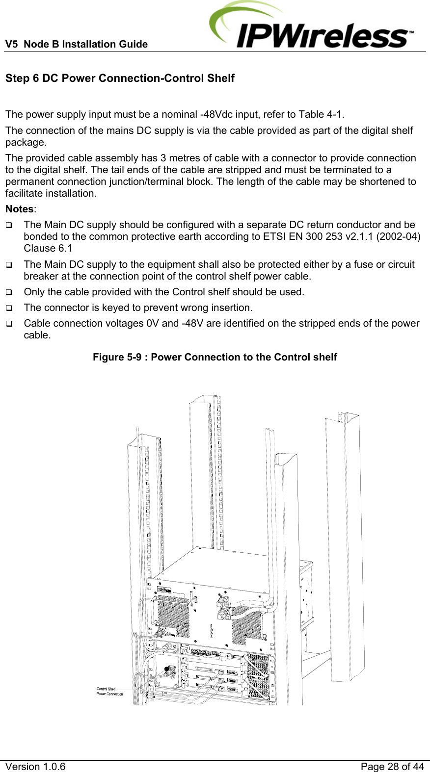
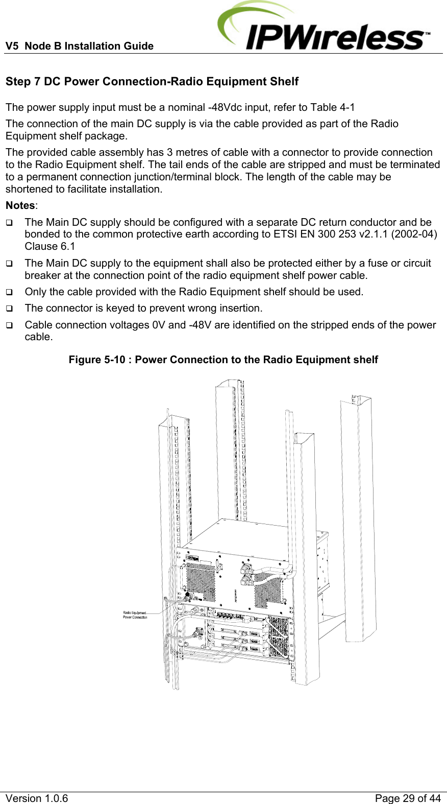
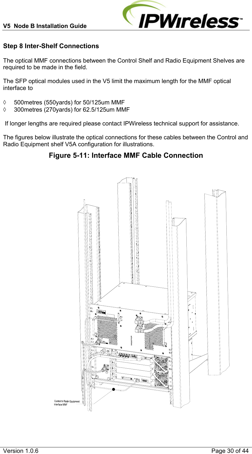
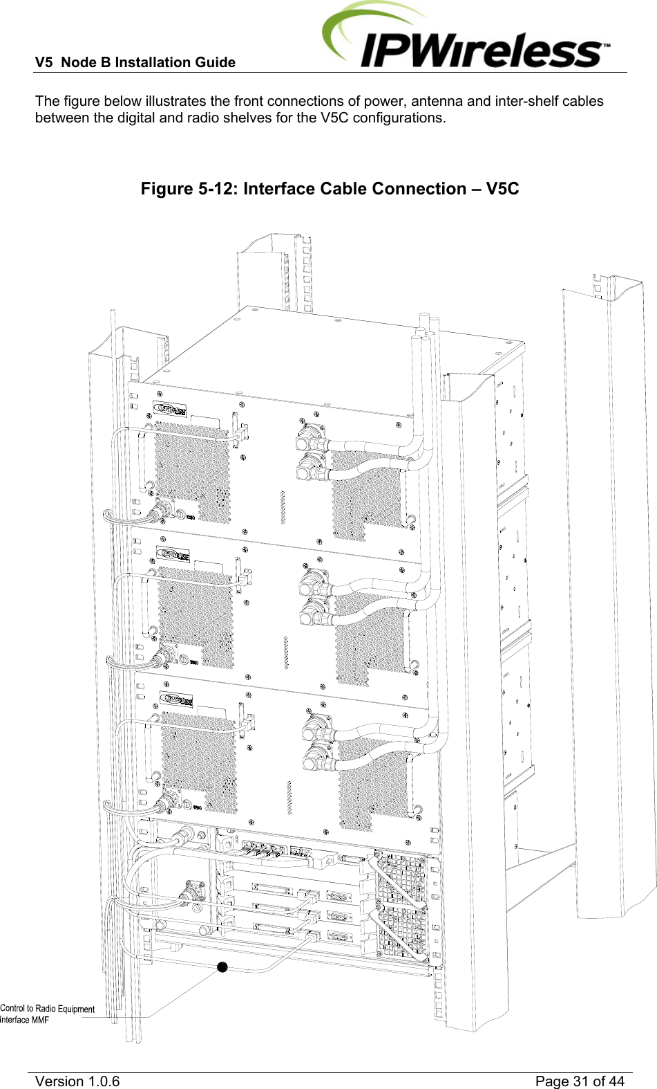
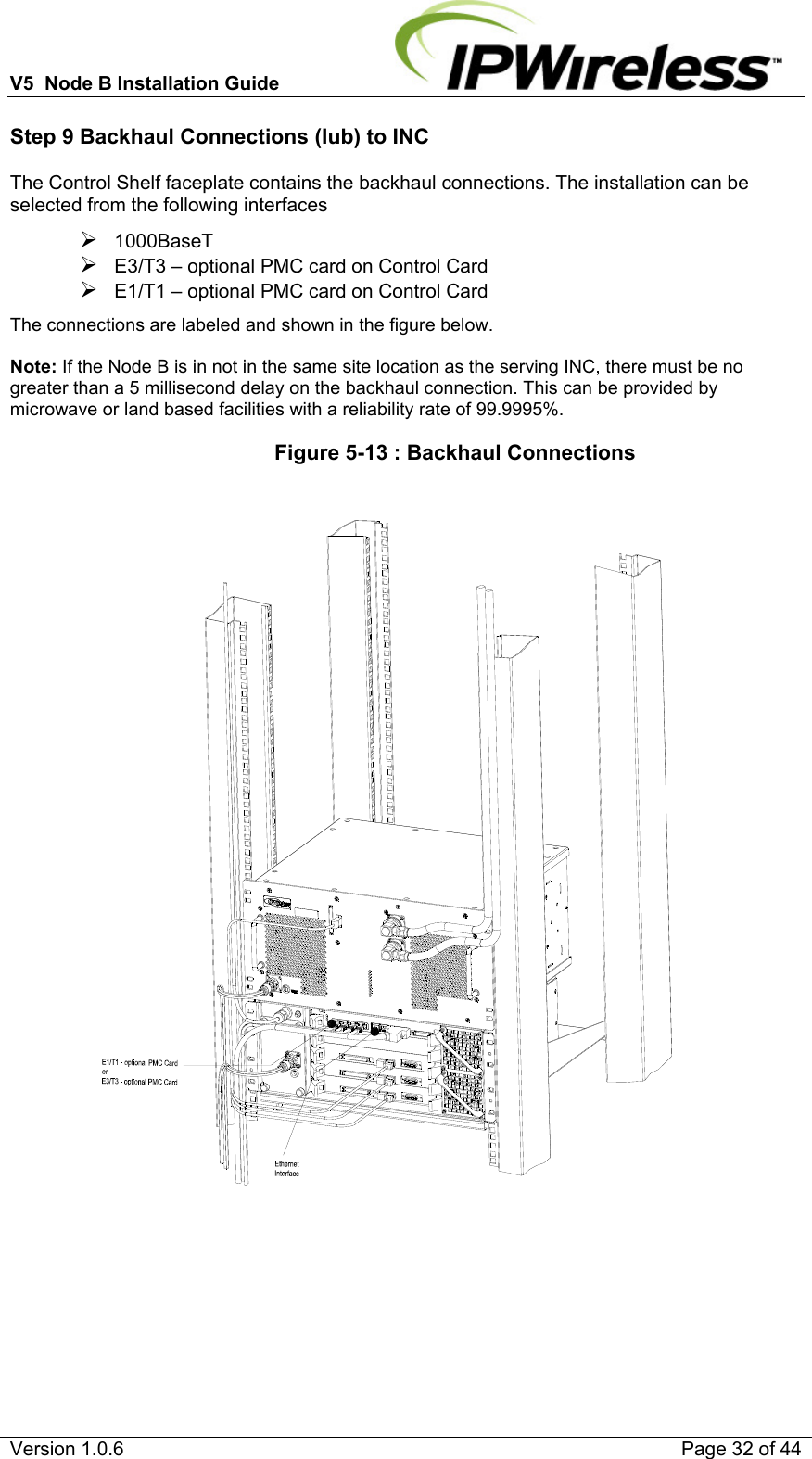
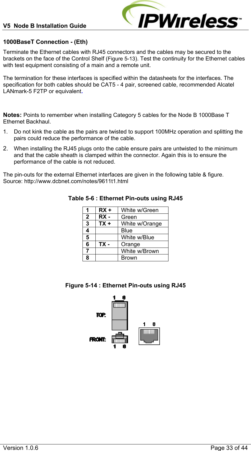
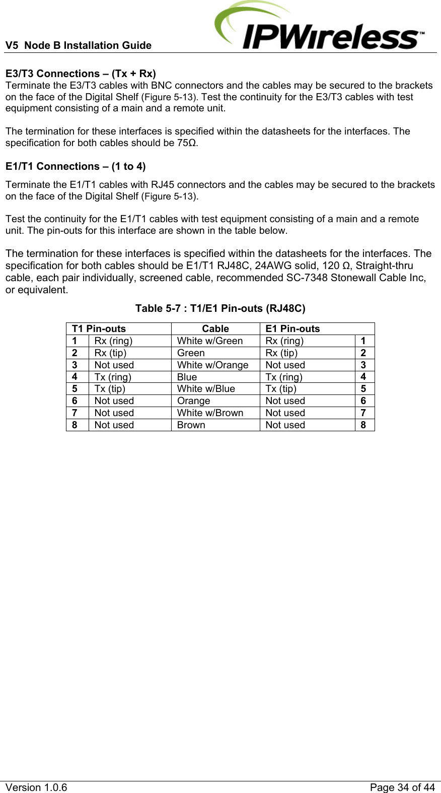
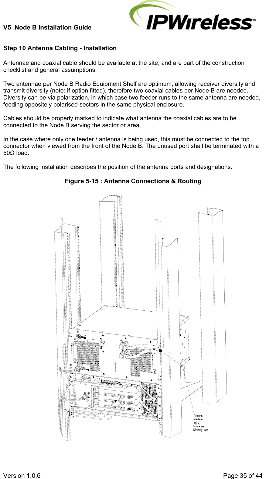
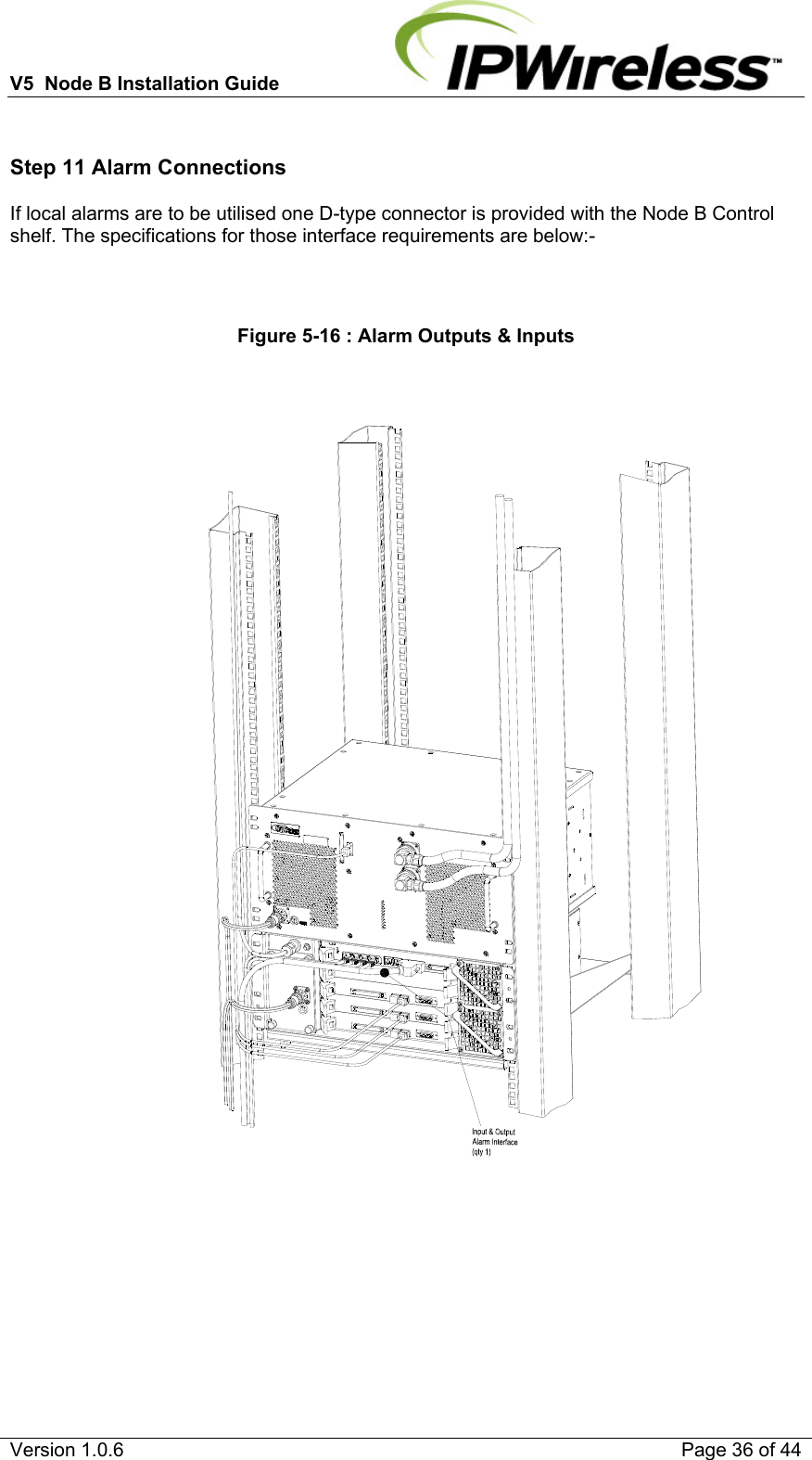
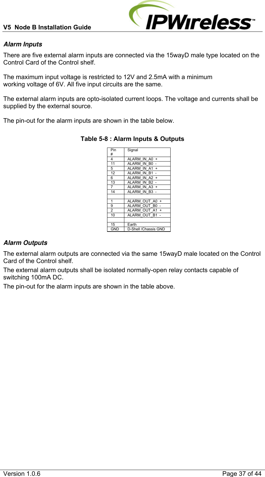
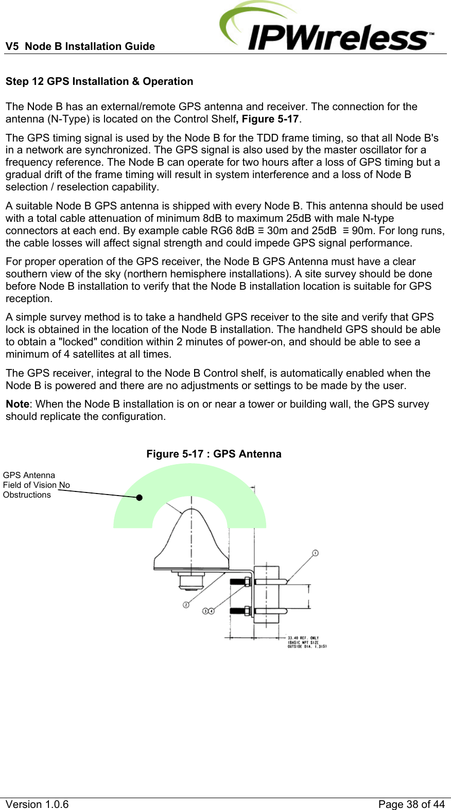
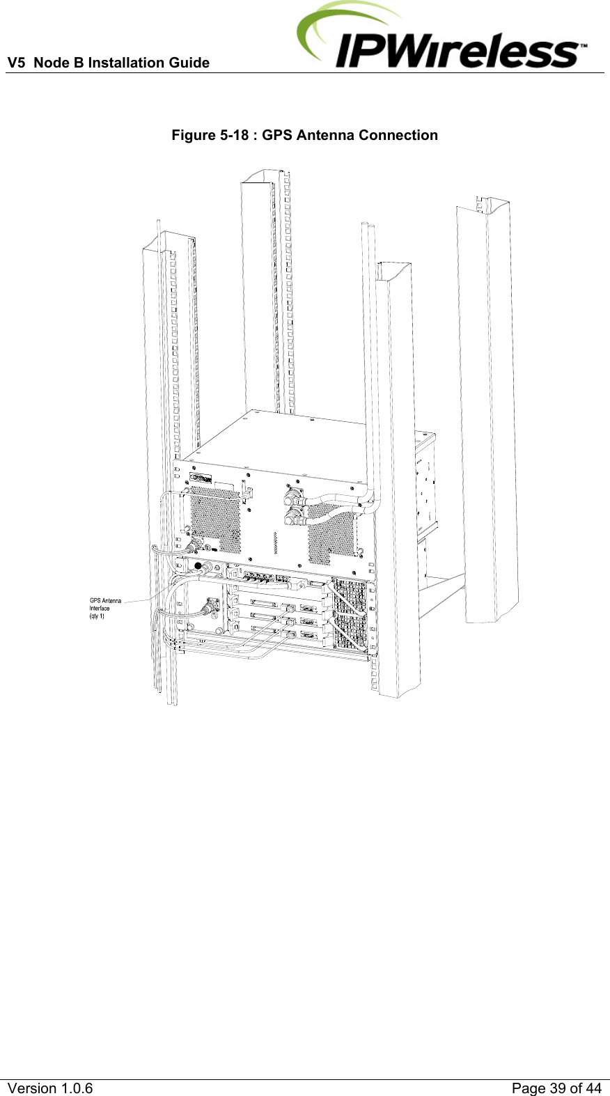
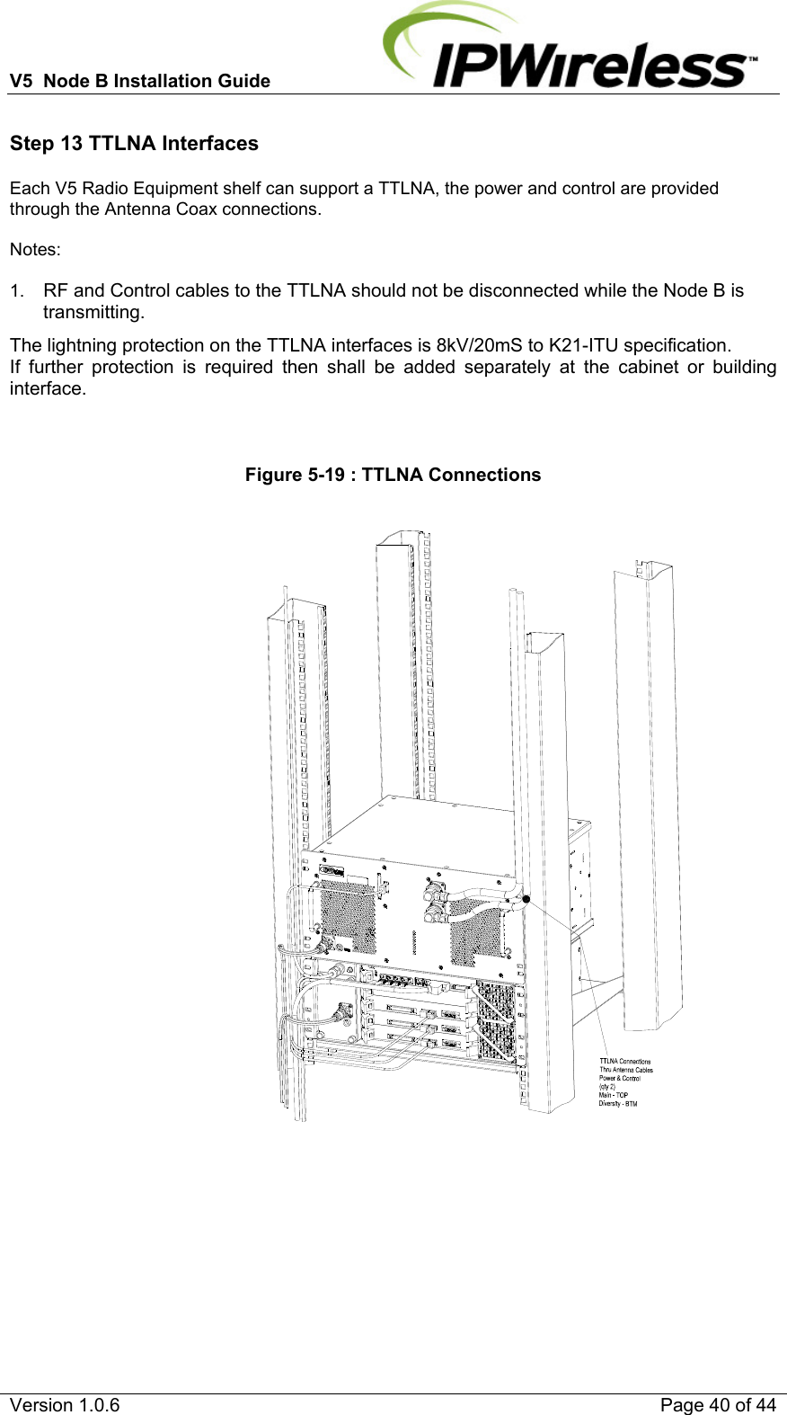
Installation Manual
Navigation menu
Upload a User Manual
Namespaces
Wiki Guide
HTML
PDF
Info
Views
User Manual
Discussion / Help
Navigation