General Dynamics Broand NODEBAMF Base Station User Manual Installation Manual
General Dynamics Broadband, Inc. Base Station Installation Manual
Installation Manual
V5 Node B Installation Guide
Version 1.0.6 Page 1 of 44
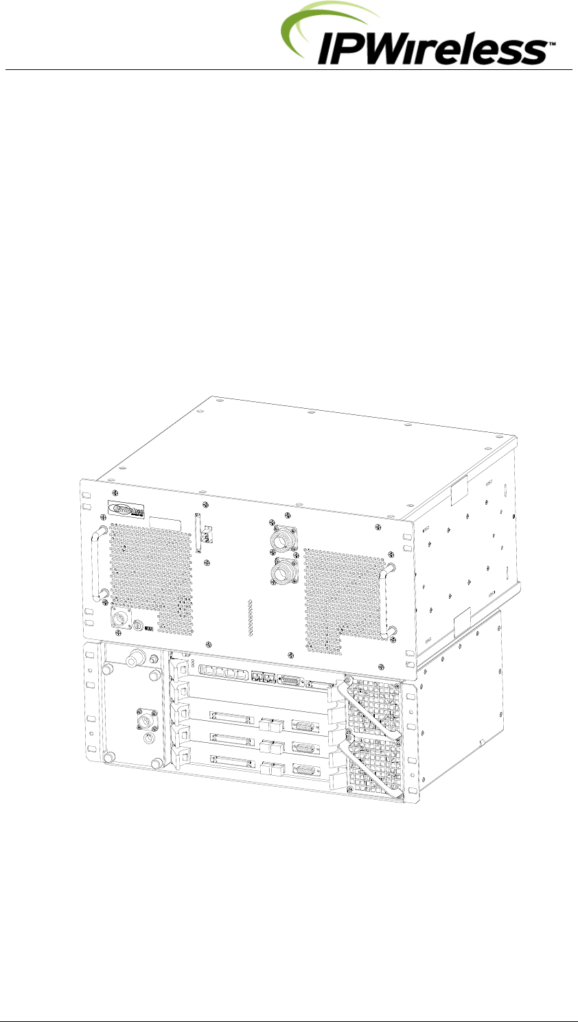
V5 Node B
Installation Guide

V5 Node B Installation Guide
Version 1.0.6 Page 2 of 44
Information in this document and the products described are subject to change
without notice.
©2000-2007 IPWireless, Inc. All rights reserved.
Reproduction, alteration, or distribution in any manner whatsoever without the written
permission of IPWireless Inc, is strictly forbidden.
Trademarks used in this text: the IPWireless logo, icon and IPWireless Broadband Modem
are trademarks of IPWireless, Inc.; Microsoft, Windows, and Windows NT are registered
trademarks of Microsoft Corporation.
Other trademarks and trade names may be used in this document to refer to either the
entities claiming the marks and names or their products, IPWireless, Inc., disclaims any
proprietary interest in trademarks and trade names other than its own.
February 2010 Part No. IPW-1442

V5 Node B Installation Guide
Version 1.0.6 Page 3 of 44
WEEE Compliance
In compliance with the requirements for marking electrical and electronic equipment as
directed in article 11 (2) of Directive 2002/96/EC, Waste from Electrical and Electronic
Equipment (WEEE), IPWireless applies a crossed-out bin symbol to all Node B products.
The mark signifies that the IPWireless equipment is to be reprocessed or recycled using
IPWireless authorized recyclers and processes.
This minimizes the disposal of unsorted municipal waste, achieves a high level of separate
collection of WEEE, and ensures the environmentally sound disposal of electrical and
electronic equipment placed on the market after 13 August 2005.
To dispose of equipment marked with the WEEE symbol, IPWireless has contracted with
certified companies that can reprocess this equipment per European Union requirements.
To find out further information regarding disposal of IPWireless equipment within the EU visit
the IPWireless web site, ipwireless.com, or contact your IPWireless representative.

V5 Node B Installation Guide
Version 1.0.6 Page 4 of 44
Contents
1. Release Version ..................................................................................... 6
2. Safety Precautions ................................................................................ 7
3. General Warnings .................................................................................. 7
4. Overview ................................................................................................. 9
5. General Specifications ........................................................................ 10
6. Installation ............................................................................................ 15
Step 1 Pre-Installation ........................................................................................ 15
Step 2 Parts Shipped & Tools Required ........................................................... 16
Step 3 Site Preparations for Node B Installation ............................................. 20
Step 4 Mounting Installations ............................................................................ 24
Step 5 Ground Installation ................................................................................. 27
Step 6 DC Power Connection-Control Shelf .................................................... 28
Step 7 DC Power Connection-Radio Equipment Shelf .................................... 29
Step 8 Inter-Shelf Connections ......................................................................... 30
Step 9 Backhaul Connections (Iub) to INC ....................................................... 32
Step 9 Backhaul Connections (Iub) to INC ....................................................... 32
Step 10 Antenna Cabling - Installation ............................................................. 35
Step 11 Alarm Connections ............................................................................... 36
Step 12 GPS Installation & Operation ............................................................... 38
Step 13 TTLNA Interfaces .................................................................................. 40
7. APPENDIX ............................................................................................ 41
Appendix A - Installation Check Card ............................................................... 41
Appendix B – Glossary ...................................................................................... 42

V5 Node B Installation Guide
Version 1.0.6 Page 5 of 44
Tables
Table 2-1 : Safety Symbols ................................................................................................... 7
Table 5-1 : Specifications ................................................................................................... 10
Table 5-2 : Node B Model Types ........................................................................................ 12
Table 6-1 : Control Shelf - Packing List ............................................................................. 17
Table 6-2 : Radio Equipment Shelf - Packing List ............................................................ 18
Table 6-3 : Tools Required .................................................................................................. 19
Table 6-4 : Materials Required ............................................................................................ 19
Table 6-5 : Site Preparation Checklist ............................................................................... 20
Table 6-6 : Ethernet Pin-outs using RJ45 ......................................................................... 33
Table 6-7 : T1/E1 Pin-outs (RJ48C) .................................................................................... 34
Table 6-8 : Alarm Inputs & Outputs ................................................................................... 37
Figures
Figure 5-1 : Node B Rack Mount – Control Shelf Physical Dimensions ........................ 11
Figure 5-2 : Node B Rack Mount – Radio Equipment Physical Dimensions ................. 11
Figure 5-3 : General Description – Front View ................................................................. 12
Figure 5-4 : Control Shelf Faceplate (dims mm) ............................................................... 13
Figure 5-5 : Radio Equipment Shelf Faceplate ................................................................. 14
Figure 6-1 : Control Shelf Package + Contents ................................................................ 17
Figure 6-2 : Radio Equipment Shelf Package + Contents ............................................... 18
Figure 6-3 : Node B Rack Mount – Single Support Shelf (all cables shown) ................ 21
Figure 6-4 : V5C Node B Rack Mount – Alternative Stack-ups ....................................... 22
Figure 6-5 : Mounting Rack + Support Shelves/Rails ...................................................... 24
Figure 6-6: Installing Control Shelf .................................................................................... 25
Figure 6-7 : Installing Radio Equipment Shelf .................................................................. 26
Figure 6-8 : Earth Connection on the rear of each shelf ................................................. 27
Figure 6-9 : Power Connection to the Control shelf ........................................................ 28
Figure 6-10 : Power Connection to the Radio Equipment shelf ..................................... 29
Figure 6-11: Interface MMF Cable Connection ................................................................. 30
Figure 6-12: Interface Cable Connection – V5C ............................................................... 31
Figure 6-13 : Backhaul Connections ................................................................................. 32
Figure 6-14 : Ethernet Pin-outs using RJ45 ...................................................................... 33
Figure 6-15 : Antenna Connections & Routing ................................................................. 35
Figure 6-16 : Alarm Outputs & Inputs ................................................................................ 36
Figure 6-17 : GPS Antenna ................................................................................................. 38
Figure 6-18 : GPS Antenna Connection ............................................................................ 39
Figure 6-19 : TTLNA Connections ...................................................................................... 40

V5 Node B Installation Guide
Version 1.0.6 Page 6 of 44
1. Release Version
Date Version Author Reason For Change Issue
23rd January 2007 1.0.0 L. Mujegu First Issue
05
th
March 2007 1.0.1 L. Mujegu Additional specs on optical i/f
8
th
March 2007 1.0.2 L. Mujegu Minor typo corrections
10
th
July 2007 1.0.3 P Warburg Safety Update
10
th
August 2007 1.0.4 P Warburg FCC Regulatory Information added
29
th
January 2010 1.0.5 P Warburg FCC Regulatory Information added
4
th
February 2010 1.0.6 P Warburg FCC Regulatory Information added
V5 Node B Installation Guide
Version 1.0.6 Page 7 of 44
2. Safety Precautions
Table 2-1 : Safety Symbols
GENERAL WARNING ELECTRICAL HAZARD GROUND
GENERAL SAFETY
PRECAUTION
VOLTAGE:
Care should be taken when
servicing this area. Misuse or
inappropriate contact with
these areas could result in
physical harm and property
damage
GROUND:
Site for grounding equipment
These cautionary signs are used on the equipment and within this manual. For safety of
personnel and protection of equipment observe these precautions when installing, operating
or servicing the equipment and surrounding areas.
3. General Warnings
Electrical
Power Supply – the power cords supplied are for DC. DO NOT adapt to a different
configuration.
Power supply circuits may carry high voltages. Remove rings, watches, and other jewellery
before working with this type of equipment.
Batteries – Certain installation of this equipment may require working with lead acid
batteries, batteries present chemical, electric and gaseous hazards. Batteries are not
supplied by IPWireless for the Node B equipment although UPS systems may be coupled
with the Node B equipment in order to provide back up power in case of power outages.
Physical
Weight –The Radio Equipment or Control shelves of the Rack Node B can weigh up to
25kgs (55 pounds) each depending on configurations. Precautions should be taken,
depending on the installation site conditions, in lifting and general handling the device.
Environmental
There are different precautions to take within each installation situation. Specific
precautions are listed in the installation section for that situation.
Site Location
The Node B Rack Mount basestation is designed to be installed in restricted access
locations only. The site locations are accessible by suitably trained service/installation
personnel only.
Network Connections
The Node B Rack Mount basestation is NOT suitable for direct connection to Public
Switched Networks. This means that the Node B is NOT suitable for direct connection to
TNV circuits.

V5 Node B Installation Guide
Version 1.0.6 Page 8 of 44
FCC Regulatory Information
This device complies with Part 15 of the FCC Rules. Operation is subject to the following two
conditions: (1) this device may not cause harmful interference, and (2) this device must
accept any interference received, including interference that may cause undesired operation.
No changes shall be made to the equipment without the manufacturer’s permission as this
may void the user’s authority to operate the equipment.
To comply with FCC requirements, the V5 Node B has been approved for use with antennae
that have a maximum gain of 20dBi.
To comply with the FCC RF exposure rules, see relevant section.
The 2.5GHz V5 Node B has been evaluated against the Maximum Permissible Exposure
(MPE) limits defined in Section 1.1310 of the FCC rules for the uncontrolled environment.
During normal operation, all persons should maintain a distance of at least 1.64m from the
antenna for operation at 7.68Mcps and at least 2.31m from the antenna for operation at
3.84Mcps to ensure compliance with the MPE limits.
The 2.3GHz V5 Node B has been evaluated against the Maximum Permissible Exposure
(MPE) limits defined in Section 1.1310 of the FCC rules for the uncontrolled environment.
During normal operation, all persons should maintain a distance of at least 2.83m from the
antenna to ensure compliance with the MPE limits.
The 700MHz V5 Node B has been evaluated against the Maximum Permissible Exposure
(MPE) limits defined in Section 1.1310 of the FCC rules for the uncontrolled environment.
During normal operation, all persons should maintain a distance of at least 4.06m from the
antenna to ensure compliance with the MPE limits.

V5 Node B Installation Guide
Version 1.0.6 Page 9 of 44
Overview
Node B is the European Technical Standards Institute’s (ETSI) name for the radio base
station. The basic function of the Node B is to convert 100 BaseT, E1/T1 or E3/T3 into the
UTRAN TD-CDMA air interface used between the Node B and the 3G Modem. One V5
Node B can provide up to 3 sectors of RF coverage (V5C) and can also be configured to
operate in a pseudo-sectored mode using splitters (V5A). The Node B is controlled by an
IPWireless INC (Integrated network Controller) or other vendors’ RNC.
The Node B supports both 7.68Mcps (10MHz bandwidth) and 3.84Mcps (5MHz bandwidth)
operation.
Scope
This document covers the physical installation and mounting of the V5 Node B in a rack
installation. It contains the specific mounting requirements for installing within a rack.
Specifications for the rack or cabinet indoor or outdoor are outside the scope of this guide
and the responsibility of the customer.
Any installation must comply with the specifications within this document.
The manual does not detail custom or specialised installations or applications.
Additionally, antenna rigging/mounting, lightning protection, tower work, feeder installation /
termination are all considered to be outside the scope of this guide.
If in any doubt about the suitability of this guide to successfully install at the proposed
location, then please consult IPWireless technical support for assistance.

V5 Node B Installation Guide
Version 1.0.6 Page 10 of 44
4. General Specifications
Table 4-1 : Specifications
Unit Specification
Rack Specifications 19inch Mounting Racks with support shelves
Front Securing
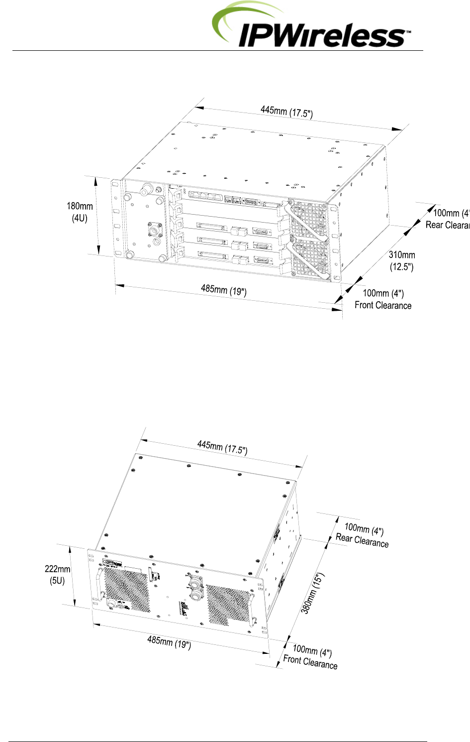
Measurements – incl front brackets Control Shelf: 180 H / (4U) x 485 W x 310 D mm
Radio Equipment Shelf: 222 H/(5U) x 485 W x 380 D mm
Measurements with front handles & cable Control Shelf: 180 H / (4U) x 485 W x 510 D mm
Radio Equipment Shelf: 222 H/(5U) x 485 W x 510 D mm
Node B Weight Control Shelf: ≤13Kgs / 28 lbs
Radio Equipment Shelf: ≤25kgs / 55 lbs
Power Consumption
Control Shelf: 350 Watts max (8Amp Fused).
Note: Fuse Size: ( ¼ x 1 ¼ inch) / (6.3 x 32 mm)
Heat Dissipation
Control Shelf 350 Watts - max
Radio Equipment Shelf – 600 Watts - max
Input Power Nominal -48 V DC
Input Range -36V to -70V DC
Ambient Operational Environment
-20ºC to +55ºC
0 to 95% Relative Humidity- Non-condensing
IP20 – IEC529
No water or Ice precipitation
All other requirements to ETS300-019 Class 3.1E
Cooling Forced Convection – Fan Assisted
Cool Air Intake front & Exhaust rear
Operating Frequencies
Note: Variant Radio Equipment shelf for each
frequency
a) 2496 MHz – 2690 MHz
b) 1900MHz – 1920MHz (20MHz or 5MHz bandwidths)
c) 2010-2025MHz
d) 3400MHz – 3615MHz
e) 698-798MHz
f) 2305-2360MHz
Connections - External
Antenna – DIN 7/16 Female (Radio Equipment shelf)
GPS – N-type Female ( Control shelf)
Power Circular Connectors – cables provided for each shelf
Ethernet – RJ45 ( Control shelf)
Optical MMF - LC-LC Duplex OM2 50/125um
E1/T1 – RJ45 ( Control shelf-Control Card) – optional PMC module
E3/T3 – BNC 75Ω ( Control shelf-Control Card) – optional PMC module
Alarm – 15wayD ( Control shelf-Control Card)
Earthing – M8 Bolt hole @ rear of each shelf
V5 Node B Installation Guide
Version 1.0.6 Page 11 of 44
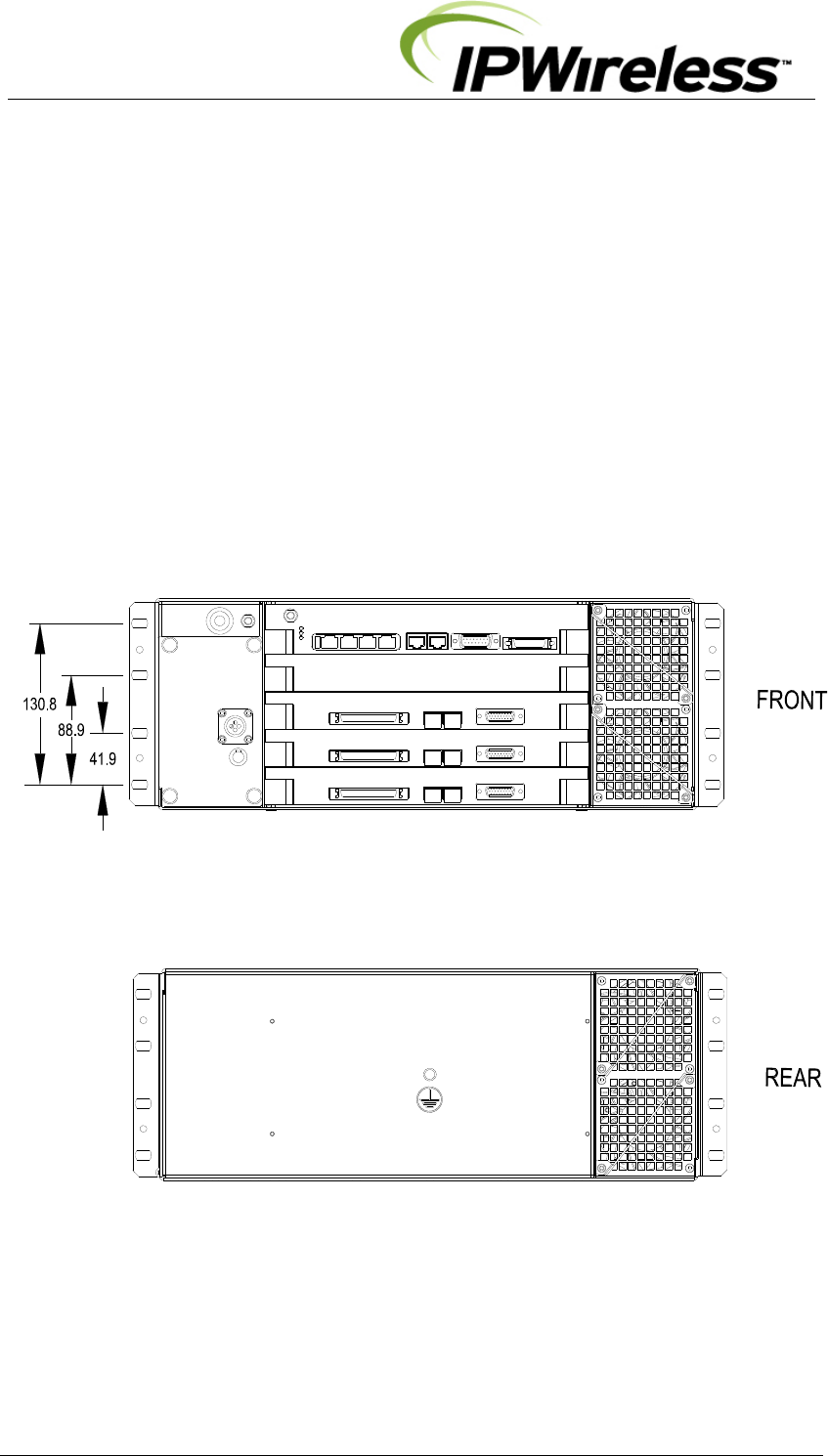
Figure 4-1 : Node B Rack Mount – Control Shelf Physical Dimensions
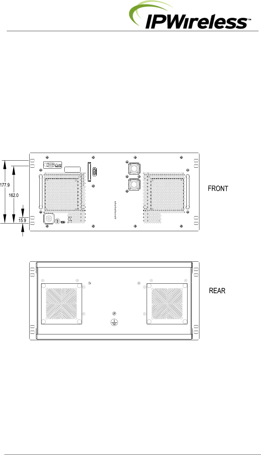
Figure 4-2 : Node B Rack Mount – Radio Equipment Physical Dimensions
V5 Node B Installation Guide
Version 1.0.6 Page 12 of 44
Table 4-2 : Node B Model Types
TxD
3.84Mcps
+40dBm
TxD
7.68Mcps
+37dBm
Non-TxD
3.84Mcps
+40dBm
Non-TxD
7.68Mcps
+37dBm
Node B Frequency
698-798 MHz √
1900-1905 MHz √ √
1905-1910 MHz √ √
1910-1915 MHz √ √
1915-1920 MHz √ √
1900-1920 MHz √ √ √ √
2010-2015 MHz √ √ √ √
2305-2360MHz √
2496-2690 MHz √ √ √ √
3400-3615 MHz √ √ √ √
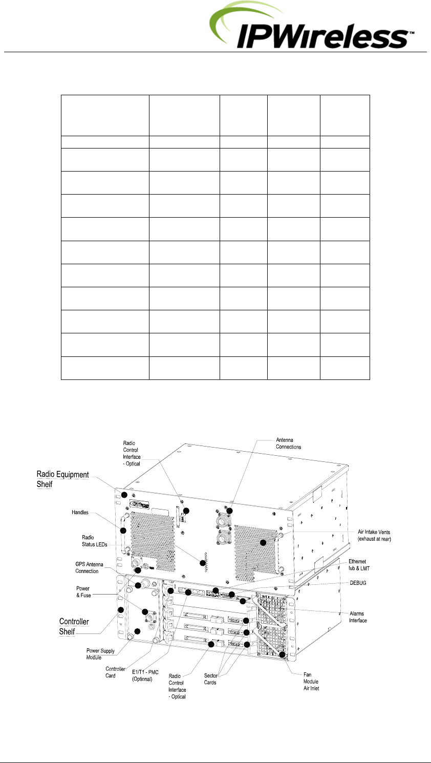
Figure 4-3 : General Description – Front View
V5 Node B Installation Guide
Version 1.0.6 Page 13 of 44
The Control shelf has the following interfaces on the front panel
¾ Mains DC supply + fuse
¾ Optical – MMF – Radio Control Interfaces
¾ IUB Interfaces
o Ethernet 1000BaseT
o or optional PMC E1/T1 or E3 / T3 (left-Rx & right-Tx)
¾ GPS Antenna Internface
¾ Alarm Interfaces – input & output
¾ LMT – 100BaseT
¾ Debug ports
On the rear the earth point and access to the rear fans.
Figure 4-4 : Control Shelf Faceplate (dims mm)
V5 Node B Installation Guide
Version 1.0.6 Page 14 of 44
The Radio Equipment shelf has the following interfaces.
¾ Mains DC supply
¾ Optical MMF – Radio Control Interfaces to Control Shelf
¾ Antenna Ports
¾ Status – LEDs
On the rear the earth point and access to the fans.
Figure 4-5 : Radio Equipment Shelf Faceplate

V5 Node B Installation Guide
Version 1.0.6 Page 15 of 44
5. Installation
This section describes the steps to be followed to physically install the Node B.
The Rack Mount installation has two basic physical configurations V5A or V5C Installation.
This section shall describe both configurations.
Step 1 Pre-Installation
The following are the initial checks that should be carried out to ensure that preparation for
the installation is complete.
For Installation Check Card please see Appendix A at the back of this manual.
1. Review site construction drawings to determine if site was constructed
according to the drawings.
2. Review drawings and actual installation to determine location of Node B
installation.
3. Check availability of electrical, grounding and antenna connections.
4. Complete site survey.
5. Check structural strength of mounting rack or frame including shelves/rails to
support Node B total weight (V5A) or multiples if a multi-sector installation, V5C,
(refer to Table 5-1).

V5 Node B Installation Guide
Version 1.0.6 Page 16 of 44
Step 2 Parts Shipped & Tools Required
This section reviews the parts, ancillary materials and tools required to install the Node B.
Use this checklist (Table 6-1 & 6-2, below) to check quantity and quality of parts as they are
unpacked.
The Control Shelf crate contains the items listed in Table 5-1 and is illustrated in Figure 5-1.
The Radio Equipment shelf crate contains the items listed Table 6-2 and illustrated in
Figure 6-2.
V5 Node B Installation Guide
Version 1.0.6 Page 17 of 44
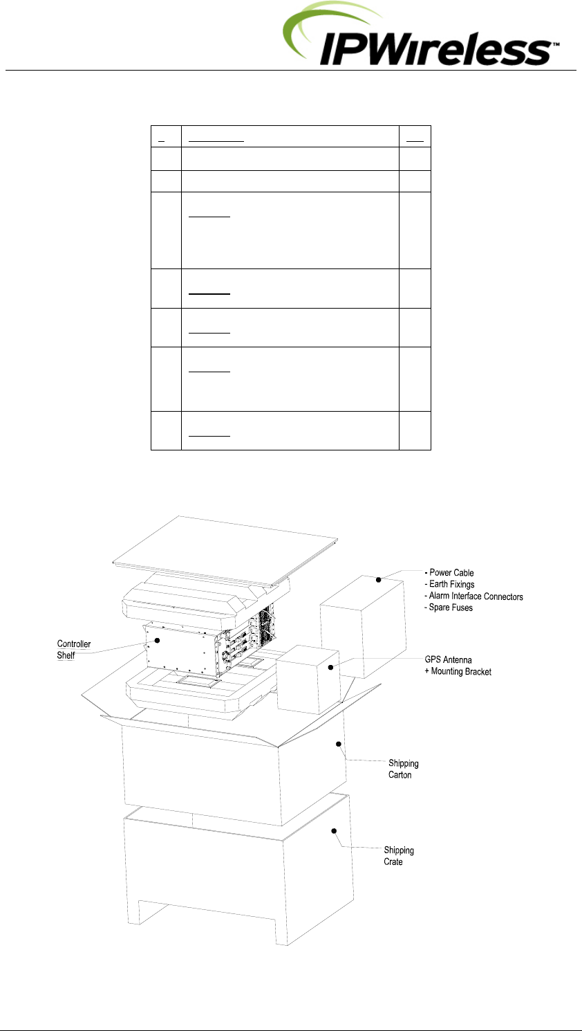
Table 5-1 : Control Shelf - Packing List
# Description Qty
Control Shelf Package - contents
1 Node B Control Shelf Unit 1
2 GPS Antenna Kit incl Mounting
contains:
1 x GPS antenna
1 x GPS antenna mounting
NOTE: The GPS kit can be supplied
separately.
1
3 Alarm Connector Kit
contains:
1 x 15wayD conn+backshell
1
4 Power Connection Kit-Digital
contains
1 x power connection – digital
1
5 Earth Fixing Kit
contains:
1 x M8 Nut
1 x M8 Spring Washer
2 x M8 Plain Washer
1
6 Fuse Kit
contains
2 x Fuse – 7A
1
Figure 5-1 : Control Shelf Package + Contents
V5 Node B Installation Guide
Version 1.0.6 Page 18 of 44
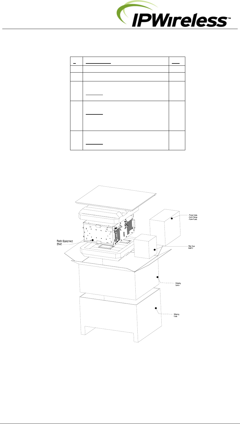
Table 5-2 : Radio Equipment Shelf - Packing List
# Description Qty
Radio Shelf Package
1 Radio Shelf Unit 1
2 Power Connection Kit-Radio
contains
1 x power connection – radio
1
3 Earth Fixing Kit
contains:
1 x M8 Nut
1 x M8 Spring Washer
2 x M8 Plain Washer
1
4 Fuse Kit
contains
2 x Fuse – 12.5A
1
Figure 5-2 : Radio Equipment Shelf Package + Contents

V5 Node B Installation Guide
Version 1.0.6 Page 19 of 44
In addition to standard construction equipment, the following tools and materials should be
available prior to installation:
Table 5-3 : Tools Required
Tools Description/Use
Basic telecommunications tool kit Includes screwdriver, socket wrenches, etc.
Voltmeter Fluke meter
Cable Stripper & Crimper RJ 45 crimper connector
Ethernet cable test set Test for all Ethernet cables
Handheld GPS with signal indicator Test for GPS signal at site location
Compass Establish antenna directions
Table 5-4 : Materials Required
Material Description
CAT5 - 4 pair, double screened cable, recommended
Alcatel LANmark-5 F2TP or equivalent IUB / LMT
RJ48C, 24AWG solid, 120 , Straight-thru cable, each
pair individually, screened cable T1 / E1 Cable
RJ45 Connectors IUB / LMT (optional T1 / E1 Connections)
CAT5 - 4 pair, double screened cable, recommended
Alcatel LANmark-5 F2TP or equivalent Alarm distribution cable
33mm2 maximum Ground cable (2AWG) Grounding termination
M8 ring terminal Grounding termination
BNC Right Angle Connectors (75) Connectors for E3/T3 Connections (optional)
RG59 B/U-LSF and UV stabilised or equivalent Cable for E3/T3 Connections
Rack mounting cage nuts + screws – note these are
required to secure the shelves to the rack
typically M6 Thread screws, washers & rack
cage nuts
Rack/Cabinet or Enclosure Installation and/or site specific
Shelf Supports or rails Specific to rack/cabinet or enclosure
DIN 7/16 antenna connections Connectors specific to antenna cable chosen
Antenna Cable Site specific selection

V5 Node B Installation Guide
Version 1.0.6 Page 20 of 44
Step 3 Site Preparations for Node B Installation
The section specifies the facilities that need to be available at the site prior to installation. The
table below is a site checklist that should be completed prior to installation.
It is assumed that the site has already been selected from RF network planning and site
acquisition/permission has been granted.
Table 5-5 : Site Preparation Checklist
# Facility Complete Y/N
1 Mains power supply –48Vdc plus breaker.
2 Availability of suitable Ethernet, E1/T1, E3/T3 Interfaces
3 Connections and trunking/conduits for interfaces
4 Suitable earth
5 Rack or cabinet suitable to mount the Node B
6 Clearance around the Node B for cable entry and cooling
Note: if installed within enclosure/cabinet rack the
environment for the Node B must meet the requirements as
specified in Table 5-1.
Assumptions
It is assumed that prior to Node B installation all civil, electrical distribution, structured
cabling termination work has been completed.
Additionally, all antenna rigging, feeder runs and terminations, associated lightning
protection plus grounding is complete, with certification for safety / compliance issued as
required by local regulations.
It is also strongly recommended that all VSWR plots of the feeder / antenna installations
should be available for inspection.
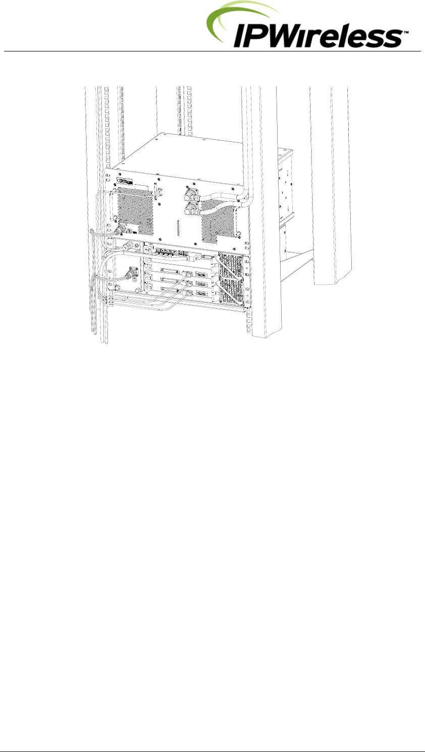
Positioning the Node B with a rack or cabinet
The Control and Radio Equipment shelves may be mounted on a single shelf/shelf
support as a pair (Figure 5-3) or can be mounted on separate shelves/supports.
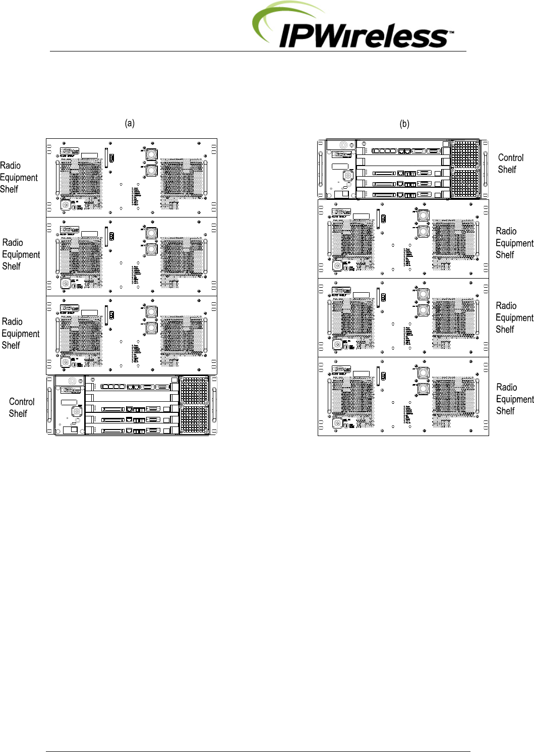
For the V5A and V5C illustrations the 1 or 3 RF shelves are shown on top with the
Control shelf. The Control shelf may be be positioned on top with the Radio Equipment
shelves as shown in Figure 5-4.
The maximum vertical distance between the shelves should not be greater than 1U
(44mm or 1 ¾”).
Selection of a suitable position for the Node B shall be done by surveying possible sites
with regard to the availability of facilities i.e. power, relative position to the INC and
consulting the site plans.
Where the Node B is directly connected to the INC ie co-sited with the INC, the Node B
should be sited not more than 100m from the INC using Shielded Category 5 Ethernet
cable as specified.
Care should be taken to position the Node B for easy front and rear access.
The Node B will need to be connected near the feeder terminations and earthing points
provided on site.
Where the Node B is installed using a microwave link ensure that the microwave link can
support the Ethernet requirements for the IUB interface i.e. 100Base-T or 10Base-T full /
half duplex as the Node B and INC. If not the Node B and INC may need to be
configured manually to support different configuration. Note: 100Base-T full duplex is
recommended.
V5 Node B Installation Guide
Version 1.0.6 Page 21 of 44
Figure 5-3 : Node B Rack Mount – Single Support Shelf (all cables shown)
V5 Node B Installation Guide
Version 1.0.6 Page 22 of 44
Figure 5-4 : V5C Node B Rack Mount – Alternative Stack-ups
ANALOGUE I/F
OPTICAL I/F
Sector
Sector
Sector
Control -/-----------------E1/T1----- ----------/- 100/1000 Base-T
Alarm I/F
Barcode
Serial No
Serial No
Barcode
Barcode
Serial No
Serial No
Barcode
Debug I/F
Optical I/F
Analogue I/F
Analogue I/F Debug I/F
Analogue I/F Debug I/F
Barcode
Serial No
POWER MO DULE
GPS
-48V DC
FUSE
6A
BASEBAND UNIT
DIGITAL SHELF
POWER
LED3
LED2
LED1 12
LED1
LED2
LED3
LED1
LED2
LED3
LED1
LED2
LED3
10/100 Base-T
10/100 Base-T
10/100 Base-T
Optical I/F
Optical I/F
Debug I/F
ANALOGUE I/F
OPTICAL I/F
ANALOGUE I/F
OPTICAL I/F
ANALOGUE I/F
OPTICAL I/F
ANALOGUE I/F
OPTICAL I/F
ANALOGUE I/F
OPTICAL I/F
Sector
Sector
Sector
Control -/-----------------E1/T1-- -------------/- 100/1000 Base-T
Alarm I/F
Barcode
Serial No
Serial No
Barcode
Barcode
Serial No
Serial No
Barcode
Debug I/F
Optical I/F
Analogue I/F
Analogue I/F Debug I/F
Analogue I/F Debug I/F
Barcode
Serial No
POWER MODULE
GPS
-48V DC
FUSE
6A
BASEBAND UNIT
DIGITAL SHELF
POWER
LED3
LED2
LED1 12
LED1
LED2
LED3
LED1
LED2
LED3
LED1
LED2
LED3
10/100 Ba se-T
10/100 Base-T
10/100 Base-T
Optical I/F
Optical I/F
Debug I/F

V5 Node B Installation Guide
Version 1.0.6 Page 23 of 44
General Considerations
The following consideration and checks are applicable to all mounting types :-
The V5 Node B is designed for indoor or weather-proof enclosure use only - refer to
Table 4-1.
Review the GPS installation guidelines (step 12) to ensure that the location will allow
proper operation of the Node B GPS remote antenna. i.e. a Southern Exposure is
required for outside installations (Northern Hemisphere), a GPS repeater may be
necessary in areas where the active GPS antenna cannot reach.
There should be a minimum clearance of 100mm in front and behind the Node B rack
mount (Figure 4-1 & Figure 5-2) for cable routing, air intake/exhaust and access to fans
at the rear.
Ensure that the rack or cabinet is sufficiently strong to support the Node B and other
equipment that may be installed with it.
The Node B requires un-restricted airflow at the front for air inlet and to the rear for air
exhaust (see figures 5-1 & 5-2).
Air filtration for the Node B environment should be specified at the cabinet/enclosure or
building level see table 5-1 for specification.
V5 Node B Installation Guide
Version 1.0.6 Page 24 of 44
Step 4 Mounting Installations
This section explains how to mount the Node B Rack Mount shelves into racks.
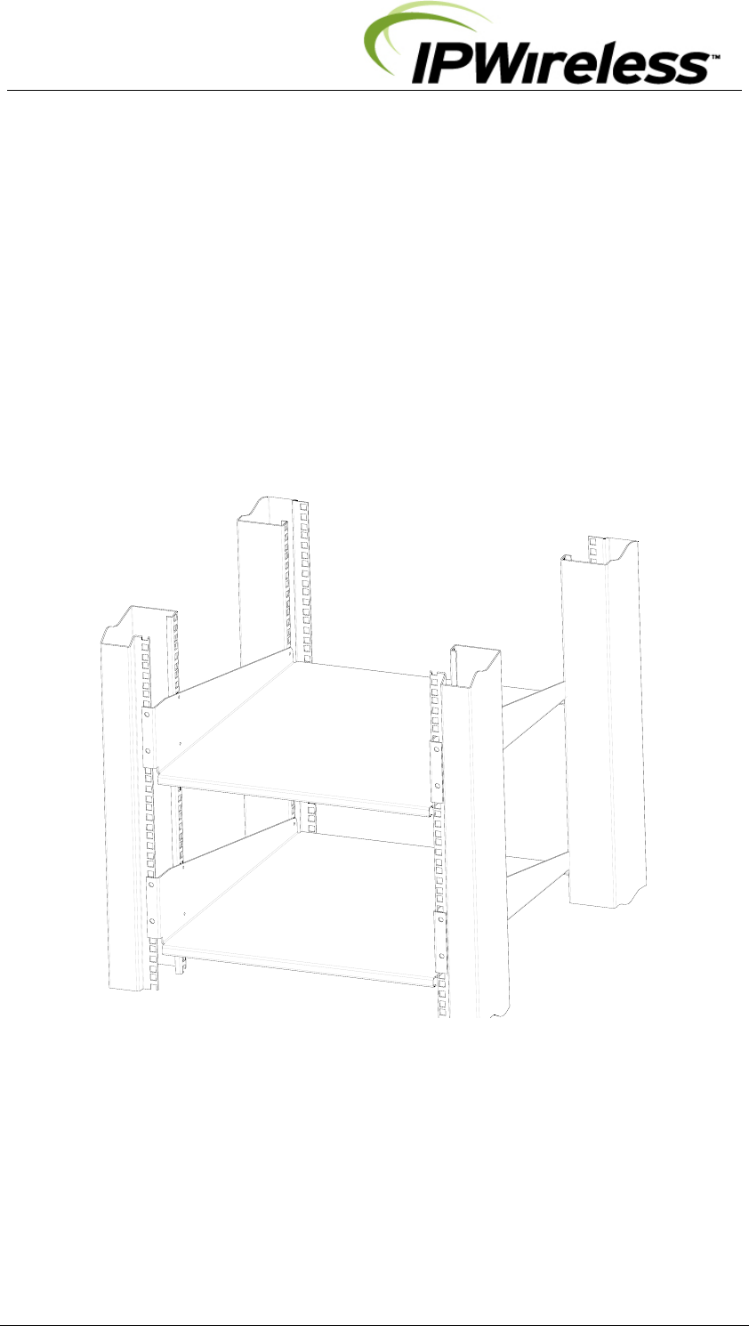
Mounting Rack
The figure below illustrates the 19inch mounting rack plus support shelves, some racks or
cabinets can use support rails. This construction can be within an enclosure or cabinet.
The support shelves or rails are specific to the rack, enclosure or cabinet being installed,
thus their specification shall be part of same selection.
Support shelves are required for easy of installation and support of the weight of the V5
Radio Equipment and Control shelves.
Figure 5-5 : Mounting Rack + Support Shelves/Rails
V5 Node B Installation Guide
Version 1.0.6 Page 25 of 44
Precautions
The following precautions and checks are applicable to all mounting types:-
Connectors have been manufactured to fit their specific cables and function. Do not
modify or force connectors.
Check Site Plans for engineering approval.
Ensure that good ground resistance is available at the installation site (10)
Where installed in an outdoor enclosure attention should be paid to cooling and
water+dust sealing prevention refer to Table 4-1.
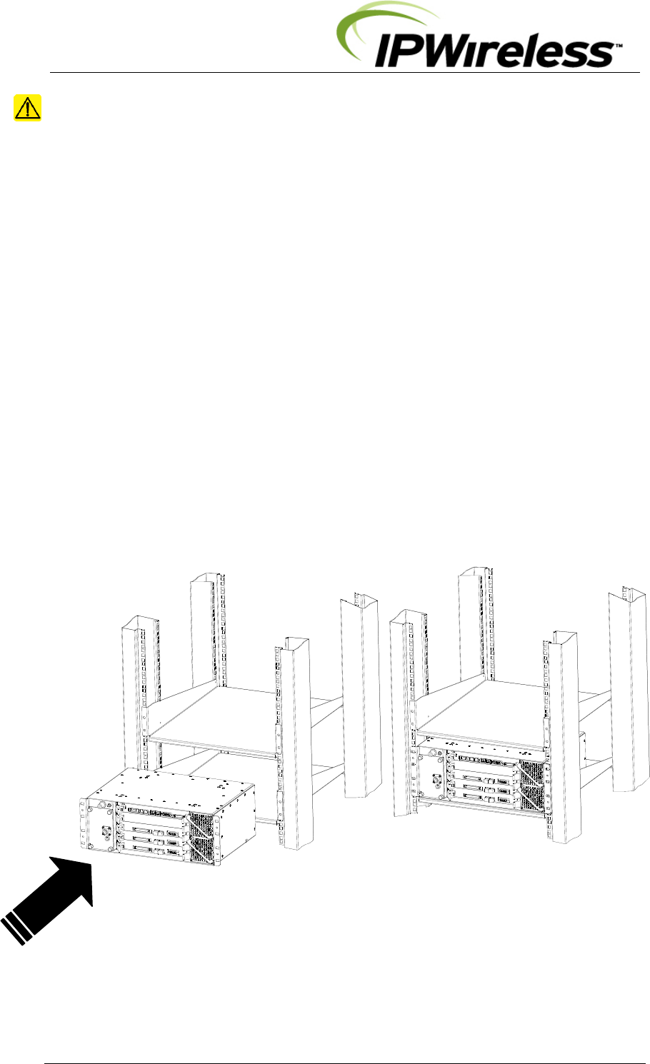
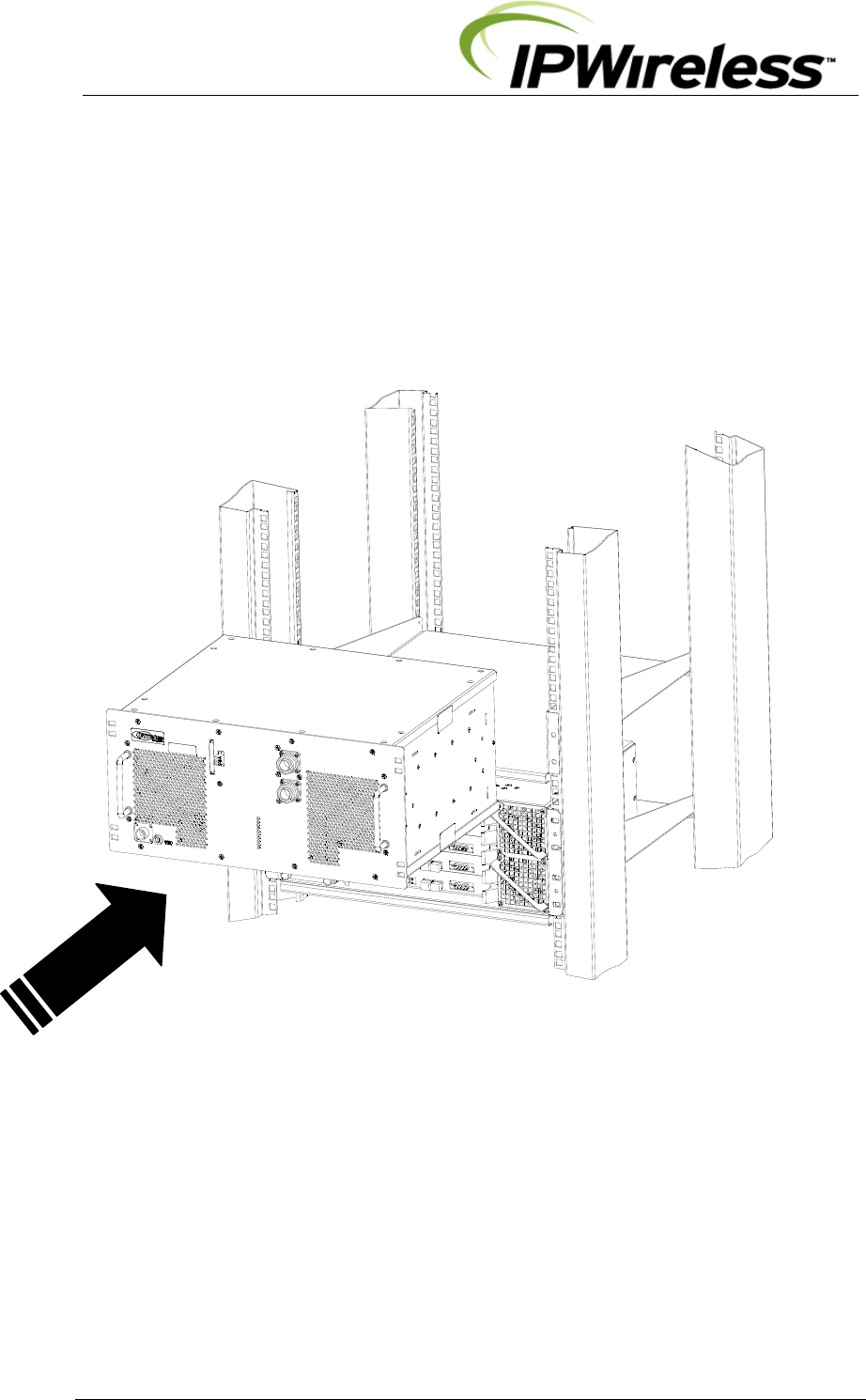
Rack Mounting – Installing Digital Shelf
Ensure the shelf or shelf supports are secure, then insert the digital shelf into the rack and
secure from the front.
Notes:
If there is no rear access it may be required to make the ground connection prior to
inserting the shelf into the rack.
Where additional securing is required at the rear this shall require custom brackets
depending on the rack specifications/construction.
Figure 5-6: Installing Control Shelf
V5 Node B Installation Guide
Version 1.0.6 Page 26 of 44
Rack Mounting – Installing Radio Equipment Shelf
Ensure the shelf or shelf supports are secure, then insert the Radio Equipment shelf into the
rack and secure from the front.
Notes:
If there is no rear access it may be required to make the ground connection prior to
inserting the shelf into the rack.
Where additional securing is required at the rear this shall require custom brackets
depending on the rack specifications/construction.
Figure 5-7 : Installing Radio Equipment Shelf
V5 Node B Installation Guide
Version 1.0.6 Page 27 of 44
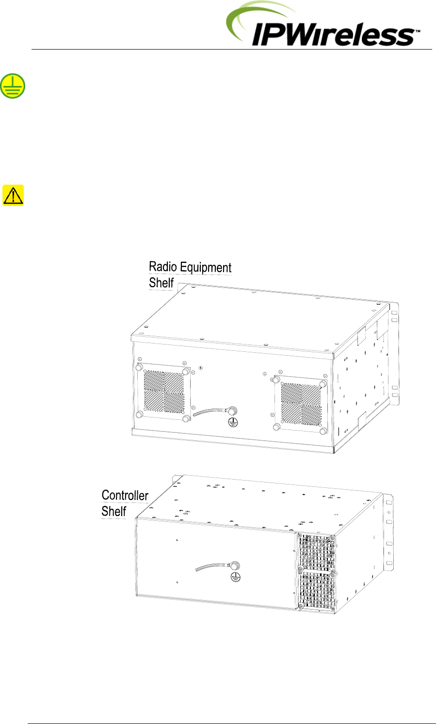
Step 5 Ground Installation
The main Node B ground cable shall use a minimum #2 AWG (Diameter 6.6mm or CSA
33mm2) stranded wire or equivalent earth braid.
The ground cable is terminated on the rear of both shelves of the Node B Rack Mount using
a terminal that shall fit the M8 bolt on the rear of each shelf.
The grounding wire is terminated onto the site grounding ring.
It should be noted that each site shall be designed for specific site, country or local
installation requirements.
CAUTION: Ensure that the earth braid or cable is bonded to a common earth with
equipment that is co-located with the Node B.
Figure 5-8 : Earth Connection on the rear of each shelf
V5 Node B Installation Guide
Version 1.0.6 Page 28 of 44
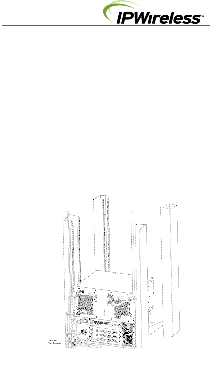
Step 6 DC Power Connection-Control Shelf
The power supply input must be a nominal -48Vdc input, refer to Table 4-1.
The connection of the mains DC supply is via the cable provided as part of the digital shelf
package.
The provided cable assembly has 3 metres of cable with a connector to provide connection
to the digital shelf. The tail ends of the cable are stripped and must be terminated to a
permanent connection junction/terminal block. The length of the cable may be shortened to
facilitate installation.
Notes:
The Main DC supply should be configured with a separate DC return conductor and be
bonded to the common protective earth according to ETSI EN 300 253 v2.1.1 (2002-04)
Clause 6.1
The Main DC supply to the equipment shall also be protected either by a fuse or circuit
breaker at the connection point of the control shelf power cable.
Only the cable provided with the Control shelf should be used.
The connector is keyed to prevent wrong insertion.
Cable connection voltages 0V and -48V are identified on the stripped ends of the power
cable.
Figure 5-9 : Power Connection to the Control shelf
V5 Node B Installation Guide
Version 1.0.6 Page 29 of 44
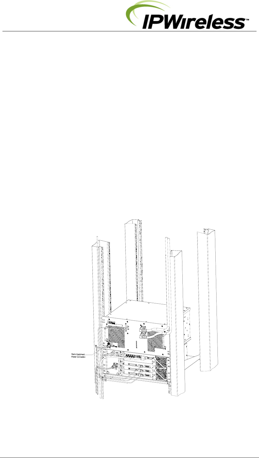
Step 7 DC Power Connection-Radio Equipment Shelf
The power supply input must be a nominal -48Vdc input, refer to Table 4-1
The connection of the main DC supply is via the cable provided as part of the Radio
Equipment shelf package.
The provided cable assembly has 3 metres of cable with a connector to provide connection
to the Radio Equipment shelf. The tail ends of the cable are stripped and must be terminated
to a permanent connection junction/terminal block. The length of the cable may be
shortened to facilitate installation.
Notes:
The Main DC supply should be configured with a separate DC return conductor and be
bonded to the common protective earth according to ETSI EN 300 253 v2.1.1 (2002-04)
Clause 6.1
The Main DC supply to the equipment shall also be protected either by a fuse or circuit
breaker at the connection point of the radio equipment shelf power cable.
Only the cable provided with the Radio Equipment shelf should be used.
The connector is keyed to prevent wrong insertion.
Cable connection voltages 0V and -48V are identified on the stripped ends of the power
cable.
Figure 5-10 : Power Connection to the Radio Equipment shelf
V5 Node B Installation Guide
Version 1.0.6 Page 30 of 44
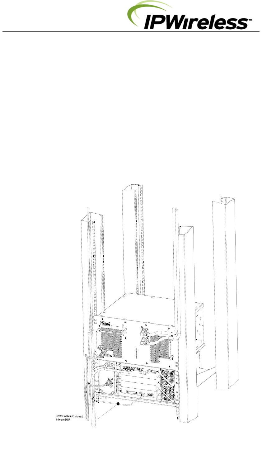
Step 8 Inter-Shelf Connections
The optical MMF connections between the Control Shelf and Radio Equipment Shelves are
required to be made in the field.
The SFP optical modules used in the V5 limit the maximum length for the MMF optical
interface to
◊ 500metres (550yards) for 50/125um MMF
◊ 300metres (270yards) for 62.5/125um MMF
If longer lengths are required please contact IPWireless technical support for assistance.
The figures below illustrate the optical connections for these cables between the Control and
Radio Equipment shelf V5A configuration for illustrations.
Figure 5-11: Interface MMF Cable Connection
V5 Node B Installation Guide
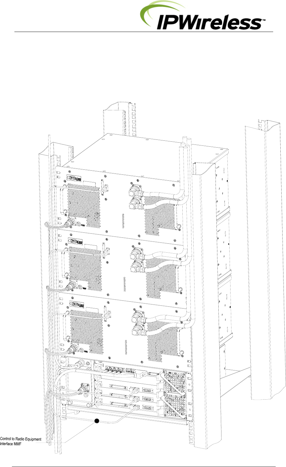
Version 1.0.6 Page 31 of 44
The figure below illustrates the front connections of power, antenna and inter-shelf cables
between the digital and radio shelves for the V5C configurations.
Figure 5-12: Interface Cable Connection – V5C
V5 Node B Installation Guide
Version 1.0.6 Page 32 of 44
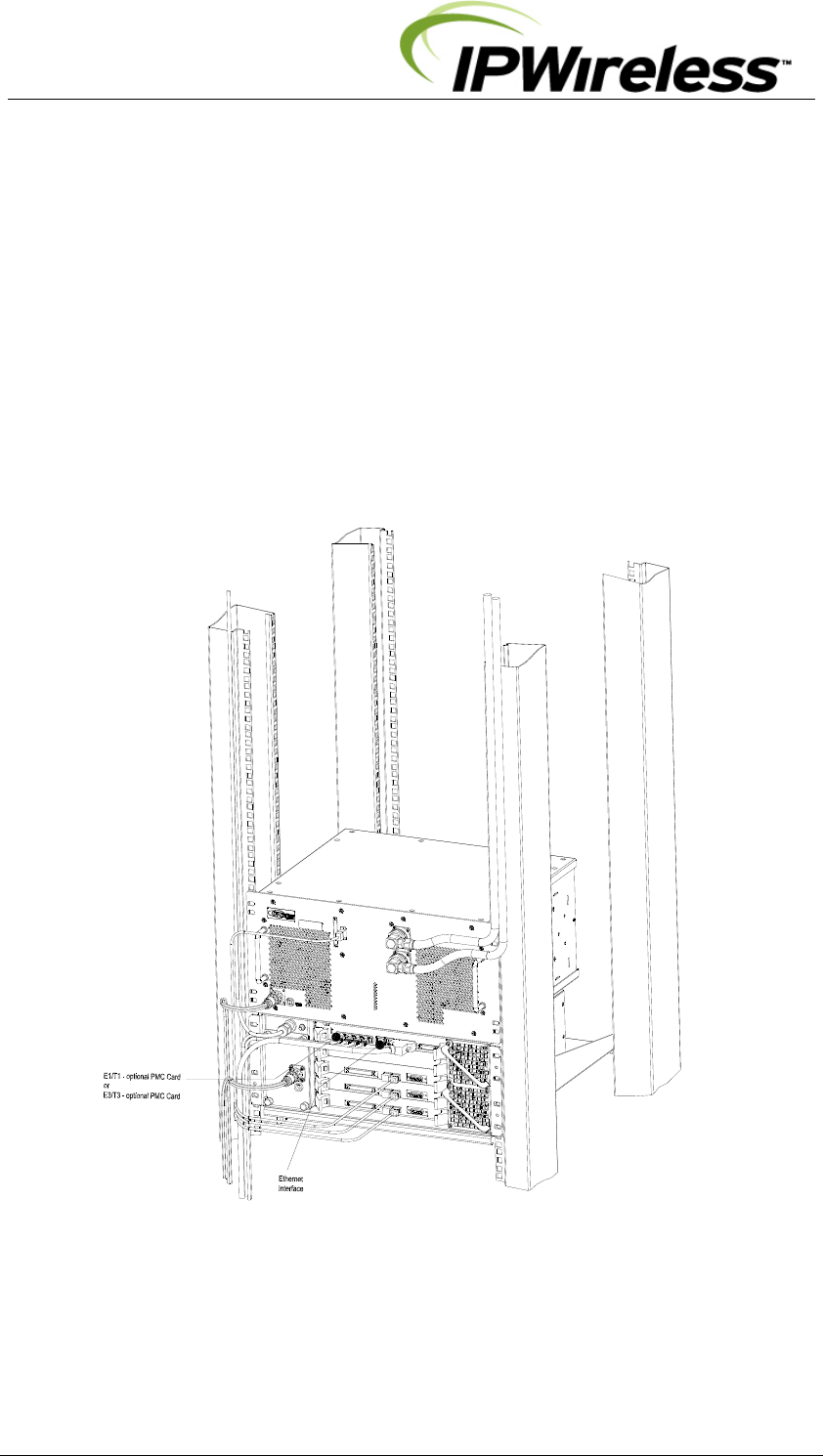
Step 9 Backhaul Connections (Iub) to INC
The Control Shelf faceplate contains the backhaul connections. The installation can be
selected from the following interfaces
¾ 1000BaseT
¾ E3/T3 – optional PMC card on Control Card
¾ E1/T1 – optional PMC card on Control Card
The connections are labeled and shown in the figure below.
Note: If the Node B is in not in the same site location as the serving INC, there must be no
greater than a 5 millisecond delay on the backhaul connection. This can be provided by
microwave or land based facilities with a reliability rate of 99.9995%.
Figure 5-13 : Backhaul Connections
V5 Node B Installation Guide
Version 1.0.6 Page 33 of 44
1000BaseT Connection - (Eth)
Terminate the Ethernet cables with RJ45 connectors and the cables may be secured to the
brackets on the face of the Control Shelf (Figure 5-13). Test the continuity for the Ethernet cables
with test equipment consisting of a main and a remote unit.
The termination for these interfaces is specified within the datasheets for the interfaces. The
specification for both cables should be CAT5 - 4 pair, screened cable, recommended Alcatel
LANmark-5 F2TP or equivalent.
Notes: Points to remember when installing Category 5 cables for the Node B 1000Base T
Ethernet Backhaul.
1. Do not kink the cable as the pairs are twisted to support 100MHz operation and splitting the
pairs could reduce the performance of the cable.
2. When installing the RJ45 plugs onto the cable ensure pairs are untwisted to the minimum
and that the cable sheath is clamped within the connector. Again this is to ensure the
performance of the cable is not reduced.
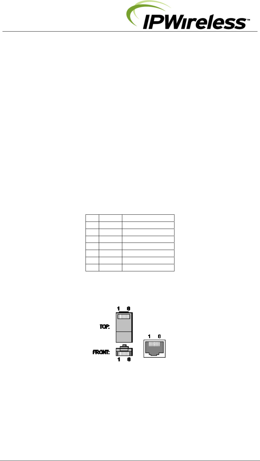
The pin-outs for the external Ethernet interfaces are given in the following table & figure.
Source: http://www.dcbnet.com/notes/9611t1.html
Table 5-6 : Ethernet Pin-outs using RJ45
1 RX + White w/Green
2 RX - Green
3 TX + White w/Orange
4 Blue
5 White w/Blue
6 TX - Orange
7 White w/Brown
8 Brown
Figure 5-14 : Ethernet Pin-outs using RJ45
V5 Node B Installation Guide
Version 1.0.6 Page 34 of 44
E3/T3 Connections – (Tx + Rx)
Terminate the E3/T3 cables with BNC connectors and the cables may be secured to the brackets
on the face of the Digital Shelf (Figure 5-13). Test the continuity for the E3/T3 cables with test
equipment consisting of a main and a remote unit.
The termination for these interfaces is specified within the datasheets for the interfaces. The
specification for both cables should be 75.
E1/T1 Connections – (1 to 4)
Terminate the E1/T1 cables with RJ45 connectors and the cables may be secured to the brackets
on the face of the Digital Shelf (Figure 5-13).
Test the continuity for the E1/T1 cables with test equipment consisting of a main and a remote
unit. The pin-outs for this interface are shown in the table below.
The termination for these interfaces is specified within the datasheets for the interfaces. The
specification for both cables should be E1/T1 RJ48C, 24AWG solid, 120 , Straight-thru
cable, each pair individually, screened cable, recommended SC-7348 Stonewall Cable Inc,
or equivalent.
Table 5-7 : T1/E1 Pin-outs (RJ48C)
T1 Pin-outs Cable E1 Pin-outs
1 Rx (ring) White w/Green Rx (ring) 1
2 Rx (tip) Green Rx (tip) 2
3 Not used White w/Orange Not used 3
4 Tx (ring) Blue Tx (ring) 4
5 Tx (tip) White w/Blue Tx (tip) 5
6 Not used Orange Not used 6
7 Not used White w/Brown Not used 7
8 Not used Brown Not used 8
V5 Node B Installation Guide
Version 1.0.6 Page 35 of 44
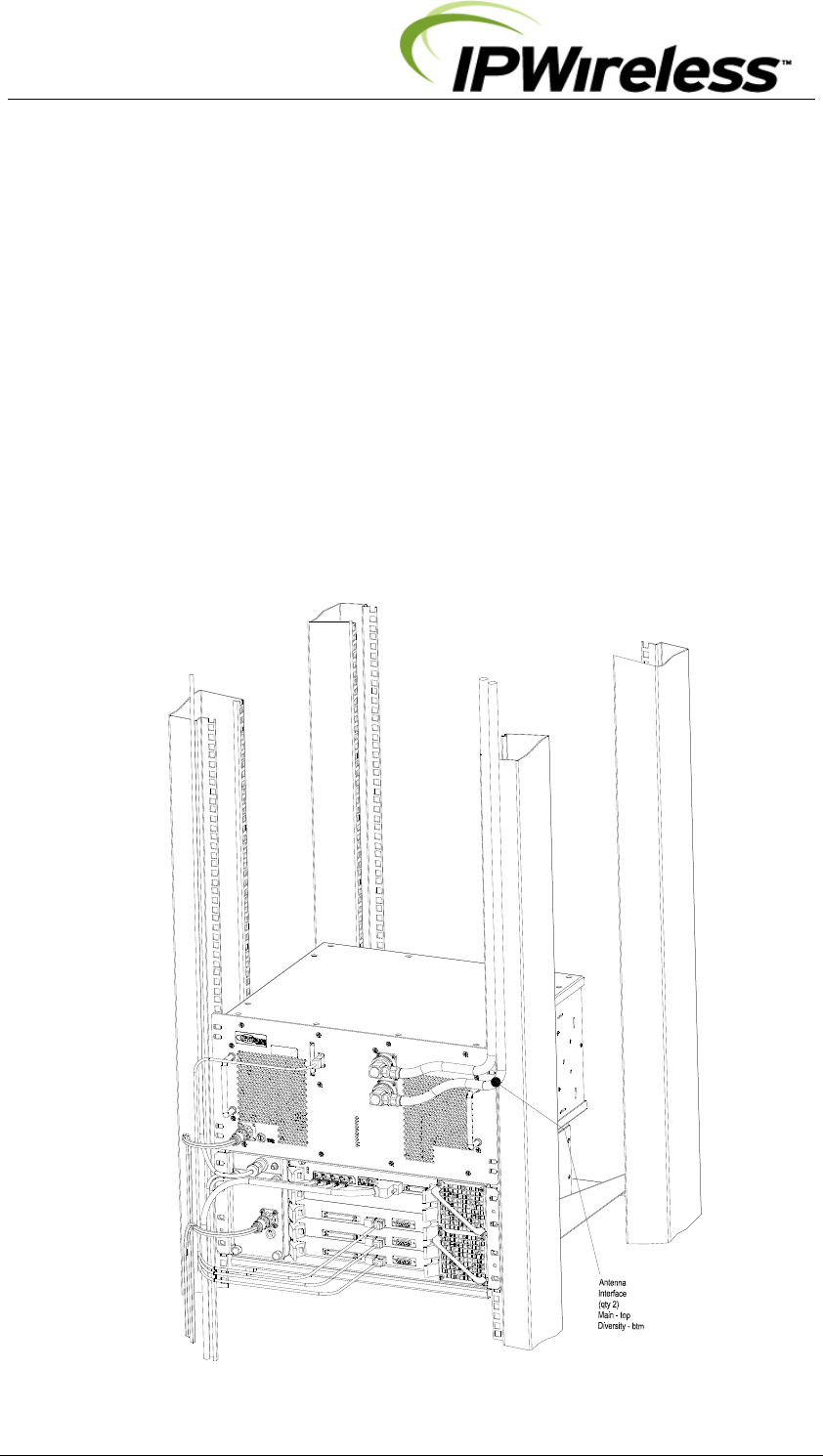
Step 10 Antenna Cabling - Installation
Antennae and coaxial cable should be available at the site, and are part of the construction
checklist and general assumptions.
Two antennae per Node B Radio Equipment Shelf are optimum, allowing receiver diversity and
transmit diversity (note: if option fitted), therefore two coaxial cables per Node B are needed.
Diversity can be via polarization, in which case two feeder runs to the same antenna are needed,
feeding oppositely polarised sectors in the same physical enclosure.
Cables should be properly marked to indicate what antenna the coaxial cables are to be
connected to the Node B serving the sector or area.
In the case where only one feeder / antenna is being used, this must be connected to the top
connector when viewed from the front of the Node B. The unused port shall be terminated with a
50 load.
The following installation describes the position of the antenna ports and designations.
Figure 5-15 : Antenna Connections & Routing
V5 Node B Installation Guide
Version 1.0.6 Page 36 of 44
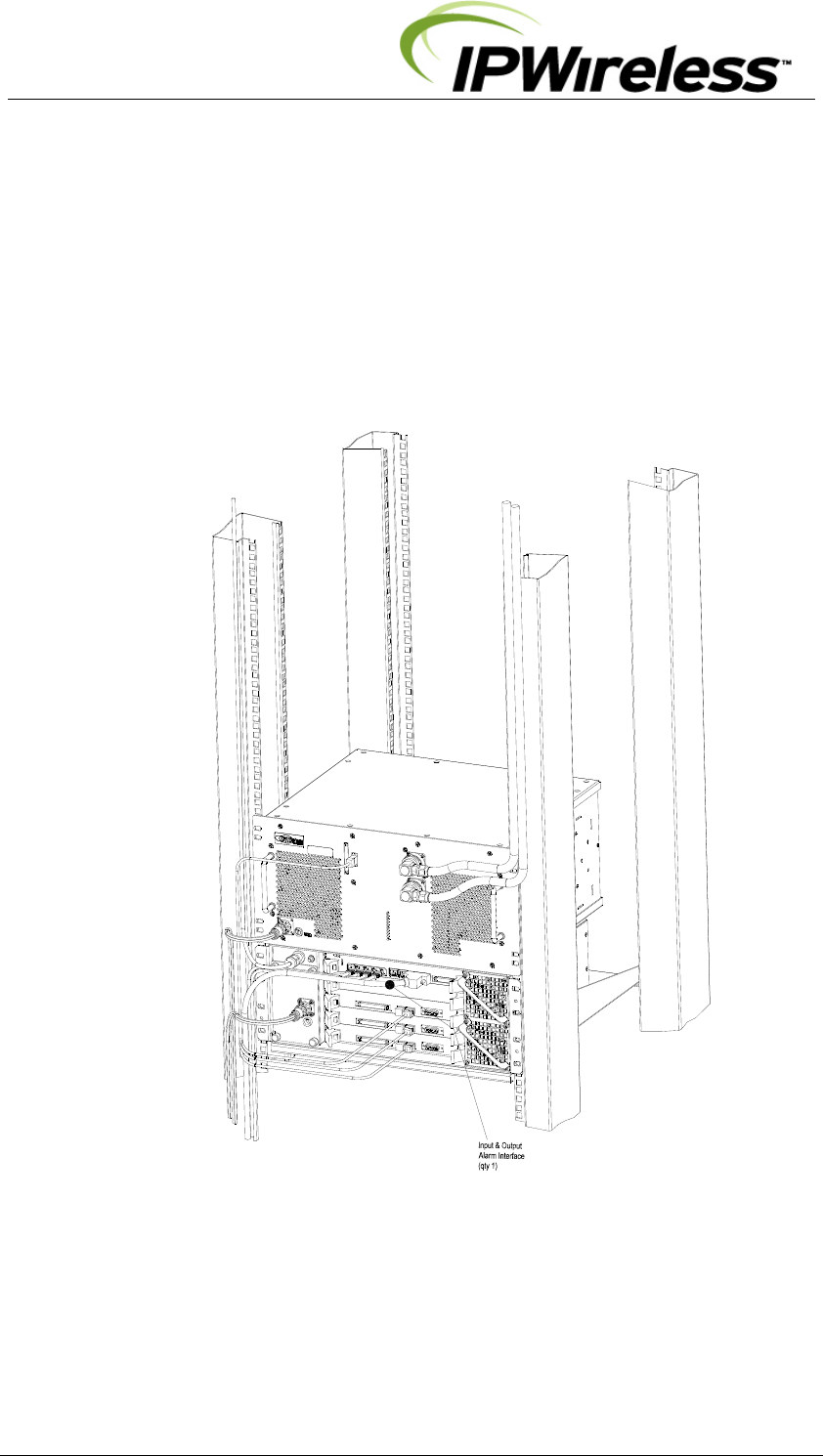
Step 11 Alarm Connections
If local alarms are to be utilised one D-type connector is provided with the Node B Control
shelf. The specifications for those interface requirements are below:-
Figure 5-16 : Alarm Outputs & Inputs
V5 Node B Installation Guide
Version 1.0.6 Page 37 of 44
Alarm Inputs
There are five external alarm inputs are connected via the 15wayD male type located on the
Control Card of the Control shelf.
The maximum input voltage is restricted to 12V and 2.5mA with a minimum
working voltage of 6V. All five input circuits are the same.
The external alarm inputs are opto-isolated current loops. The voltage and currents shall be
supplied by the external source.
The pin-out for the alarm inputs are shown in the table below.
Table 5-8 : Alarm Inputs & Outputs
Pin
#
Signal
4 ALARM_IN_A0 +
11 ALARM_IN_B0 -
5 ALARM_IN_A1 +
12 ALARM_IN_B1 -
6 ALARM_IN_A2 +
13 ALARM_IN_B2 -
7 ALARM_IN_A3 +
14 ALARM_IN_B3 -
1 ALARM_OUT_A0 +
9 ALARM_OUT_B0 -
2 ALARM_OUT_A1 +
10 ALARM_OUT_B1 -
15 Earth
GND D-Shell /Chassis GND
Alarm Outputs
The external alarm outputs are connected via the same 15wayD male located on the Control
Card of the Control shelf.
The external alarm outputs shall be isolated normally-open relay contacts capable of
switching 100mA DC.
The pin-out for the alarm inputs are shown in the table above.
V5 Node B Installation Guide
Version 1.0.6 Page 38 of 44
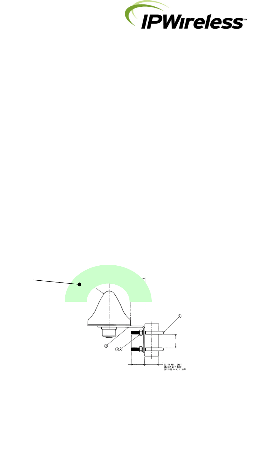
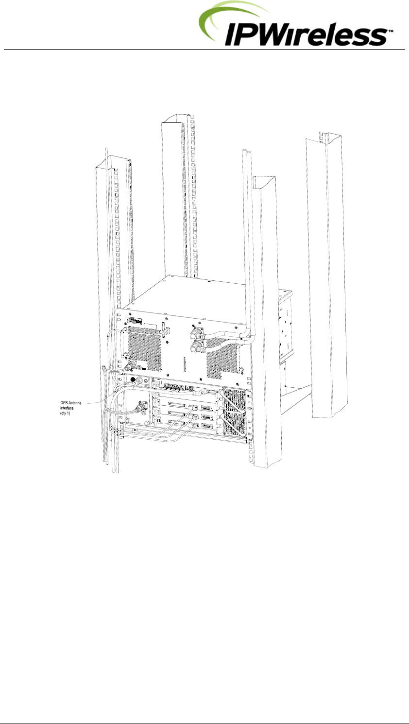
Step 12 GPS Installation & Operation
The Node B has an external/remote GPS antenna and receiver. The connection for the
antenna (N-Type) is located on the Control Shelf, Figure 5-17.
The GPS timing signal is used by the Node B for the TDD frame timing, so that all Node B's
in a network are synchronized. The GPS signal is also used by the master oscillator for a
frequency reference. The Node B can operate for two hours after a loss of GPS timing but a
gradual drift of the frame timing will result in system interference and a loss of Node B
selection / reselection capability.
A suitable Node B GPS antenna is shipped with every Node B. This antenna should be used
with a total cable attenuation of minimum 8dB to maximum 25dB with male N-type
connectors at each end. By example cable RG6 8dB 30m and 25dB 90m. For long runs,
the cable losses will affect signal strength and could impede GPS signal performance.
For proper operation of the GPS receiver, the Node B GPS Antenna must have a clear
southern view of the sky (northern hemisphere installations). A site survey should be done
before Node B installation to verify that the Node B installation location is suitable for GPS
reception.
A simple survey method is to take a handheld GPS receiver to the site and verify that GPS
lock is obtained in the location of the Node B installation. The handheld GPS should be able
to obtain a "locked" condition within 2 minutes of power-on, and should be able to see a
minimum of 4 satellites at all times.
The GPS receiver, integral to the Node B Control shelf, is automatically enabled when the
Node B is powered and there are no adjustments or settings to be made by the user.
Note: When the Node B installation is on or near a tower or building wall, the GPS survey
should replicate the configuration.
Figure 5-17 : GPS Antenna
GPS Antenna
Field of Vision No
Obstructions
V5 Node B Installation Guide
Version 1.0.6 Page 39 of 44
Figure 5-18 : GPS Antenna Connection
V5 Node B Installation Guide
Version 1.0.6 Page 40 of 44
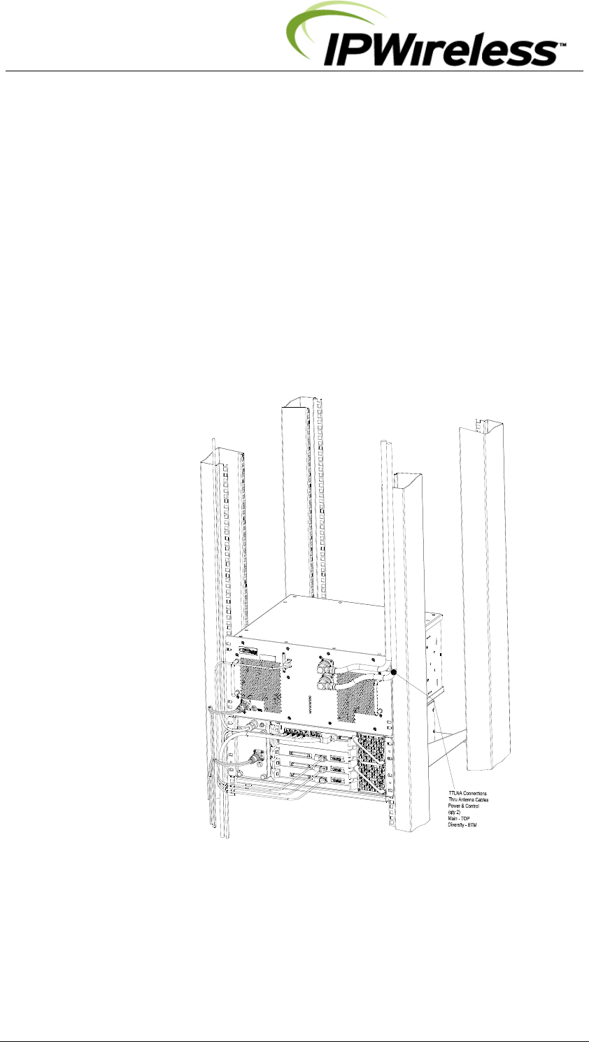
Step 13 TTLNA Interfaces
Each V5 Radio Equipment shelf can support a TTLNA, the power and control are provided
through the Antenna Coax connections.
Notes:
1. RF and Control cables to the TTLNA should not be disconnected while the Node B is
transmitting.
The lightning protection on the TTLNA interfaces is 8kV/20mS to K21-ITU specification.
If further protection is required then shall be added separately at the cabinet or building
interface.
Figure 5-19 : TTLNA Connections

V5 Node B Installation Guide
Version 1.0.6 Page 41 of 44
6. APPENDIX
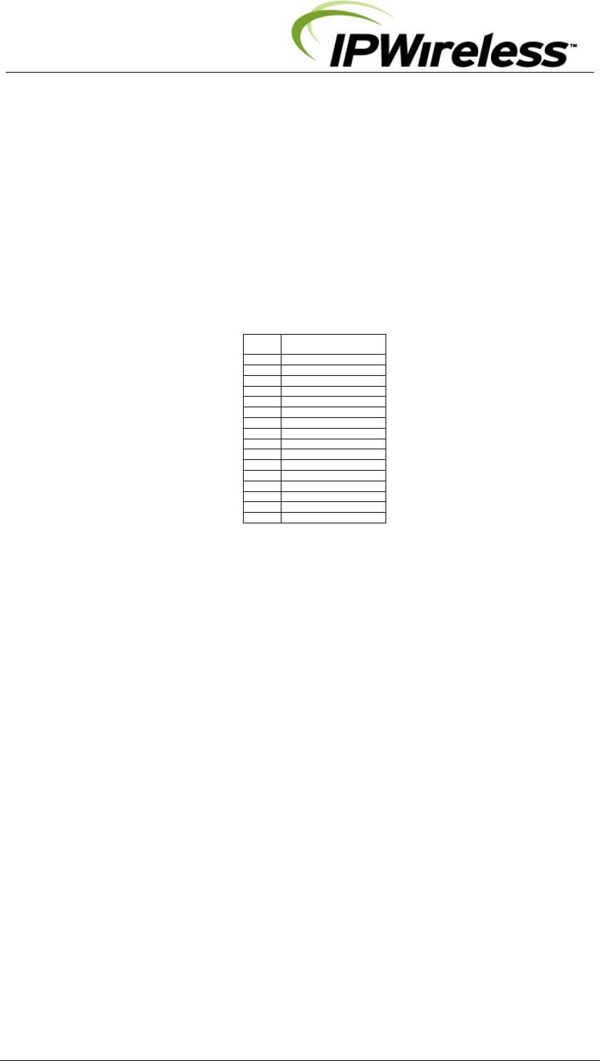
Appendix A - Installation Check Card
Step Action Complete Comment Page
1 Perform pre-installation site check
2 Parts shipped/tools required
3 Site Preparation
4 Mounting rack/cabinet installation
5 Grounding installation (all shelves)
6 DC Power Connection-Digital Shelf
7 DC Power Connection-Radio Shelf(s)
8 Inter-shelf interface connections
9 Backhaul Connections to INC
10 Antennas Cabling - Installation
11 Alarm Connections
12 GPS Installation & Operation
13 TTLNA Interfaces

V5 Node B Installation Guide
Version 1.0.6 Page 42 of 44
Appendix B – Glossary
GLOSSARY
ADC Analog to Digital Converter
ARP Address Resolution Protocol
BTS Base Transceiver Station
DAC Digital to Analog Converter
Downlink From Network to the User Equipment
DSCH Downlink Shared Channel
ESD Electro Static Discharge
EM Element Manager
EIA Engineering Industry Association
Ethernet 10BaseT or 100baseT
ETSI European Telecommunications Standardization Institute
FCC Federal Communication Commission
FPGA Field Programmable Gate Array
GPS Global Positioning System
HTTP Hyper-Text Transfer Protocol
INC Integrated Network Controller
IP Internet Protocol
ISP Internet Service Provider
ITFS Instructional Television Fixed Service
IuB Interface Between the INC & Node B
LMT Local Maintenance Terminal
LNA Low Noise Amplifier
MCP Multimedia Communications Port
MAC Media Access Control
Mcps Mega Chips per Second
MMDS Multichannel Multipoint Distribution Service
MSPS Mega Samples Per Second
MTU Maximum Transmission Unit
Node B A UMTS Radio Base Station
PDU Protocol Data Unit
PLL Phase Locked Loop
QPSK Quadrature Phase Shift Keying
RAM Random Access Memory
RLC Radio Link Control
SRAM Static RAM
T1/E1 1536kbps/ 2048Kbps pipe
T3/E3 45Mbps or 34Mbps
UE User Equipment
UMTS Universal Mobile Telecommunications System
Uplink From User Equipment to the Network

V5 Node B Installation Guide
Version 1.0.6 Page 43 of 44
GLOSSARY
USB Universal Serial Bus
USCH Uplink Shared Channel
UPS Uninterruptible Power Supply Unit
UTRAN UMTS Terrestrial Radio Access Network
VSWR Voltage Standing wave ratio
VCXO Voltage Controlled Crystal Oscillator

V5 Node B Installation Guide
Version 1.0.6 Page 44 of 44
END OF DOCUMENT