General Dynamics Broand NODEBDZ1 Wireless Broadband Base Station User Manual Part 1
General Dynamics Broadband, Inc. Wireless Broadband Base Station Part 1
Contents
- 1. User Manual Part 1
- 2. Users Manual Part 2
User Manual Part 1
Node B Rack Mount Installation Guide
Version 0.0.3 Page 1 of 39
Node B V2 Rack Mount
Installation Guide

Node B Rack Mount Installation Guide
Version 0.0.3 Page 2 of 39
Information in this document and the products described are subject to change
without notice.
2000-2003 IPWireless, Inc. All rights reserved.
Reproduction, alteration, or distribution in any manner whatsover without the written
permission of IPWireless Inc, is strictly forbidden.
Trademarks used in this text: the IPWireless logo, icon and IPWireless Broadband Modem
are trademarks of IPWireless, Inc.; Microsoft, Windows, and Windows NT are registered
trademarks of Microsoft Corporation.
Other trademarks and trade names may be used in this document to refer to either the
entities claiming the marks and names or their products, IPWireless, Inc., disclaims any
proprietary interest in trademarks and trade names other than its own.
September 2003 Part No. IPW-0695

Node B Rack Mount Installation Guide
Version 0.0.3 Page 3 of 39
Table of Contents
1.
Release Version .............................................................................................................. 5
2.
Safety Precautions........................................................................................................... 6
3.
General Warnings............................................................................................................ 6
4.
Overview.......................................................................................................................... 7
5.
General Specifications..................................................................................................... 8
6.
Installation...................................................................................................................... 13
Step 1 Pre-Installation......................................................................................13
Step 2 Parts Shipped & Tools Required ........................................................14
Step 3 Site Preparations for Node B Installation...........................................18
Step 4 Mounting Installations..........................................................................21
Step 5 Ground Installation...............................................................................23
Step 5 Ground Installation...............................................................................24
Step 6 DC Power Connection-Digital .............................................................25
Step 7 DC Power Connection-Radio..............................................................26
Step 8 Inter-Shelf Connections.......................................................................27
Step 9 Backhaul Connections (Iub) to INC....................................................28
Step 10 Antenna Cabling - Installation...........................................................31
Step 11 Alarm Connections.............................................................................32
Step 12 GPS Installation & Operation............................................................34
7.
APPENDIX..................................................................................................................... 36
Appendix A - Installation Check Card.............................................................36
Appendix B - Glossary .....................................................................................37

Node B Rack Mount Installation Guide
Version 0.0.3 Page 4 of 39
Table of Tables
Table 2-1 : Safety Sumbols ..................................................................................................... 6
Table 5-1 : Specifications ........................................................................................................ 8
Table 5-2 : Node B Model Types........................................................................................... 10
Table 6-1 : Packing List......................................................................................................... 14
Table 6-2 : Tools Required.................................................................................................... 17
Table 6-3 : Materials Required .............................................................................................. 17
Table 6-4 : Site Preparation Checklist................................................................................... 18
Table 6-5 : Ethernet Pin-outs using RJ45 ............................................................................. 29
Table 6-6 : T1/E1 Pin-outs..................................................................................................... 30
Table 6-7 : Alarm Inputs ........................................................................................................ 33
Table 6-7 : Alarm Outputs ..................................................................................................... 33
Table of Figures
Figure 5-1 : Node B Rack Mount – Digital Shelf Physical Dimensions ................................... 8
Figure 5-2 : Node B Rack Mount – RF Shelf Physical Dimensions ........................................ 9
Figure 5-3 : General Description – Front View...................................................................... 10
Figure 5-4 : Digital Shelf Faceplate ....................................................................................... 11
Figure 5-5 : Radio Shelf Faceplate
.................................................................................. 12
Figure 6-1 : Sales Pack Crate – Digital & Radio Shelf Packages.................................... 15
Figure 6-2 : Digital Shelf Package + Contents.................................................................. 15
Figure 6-3 : Radio Shelf Package + Contents ................................................................... 16
Figure 6-4 : Node B Rack Mount – Single Shelf (all cables shown) ............................... 19
Figure 6-5 : Node B Rack Mount – Double Shelf (all cables shown).............................. 19
Figure 6-6 : Mounting Rack + Support Shelves/Rails ........................................................... 21
Figure 6-7: Installing Digital Shelf...................................................................................... 22
Figure 6-8 : Installing Radio Shelf ......................................................................................... 23
Figure 6-9 : Earth Connection on the rear of each shelf ....................................................... 24
Figure 6-10 : Power Connection to the digital shelf............................................................... 25
Figure 6-11 : Power Connection to the radio shelf................................................................ 26
Figure 6-12: Interface Cable Connection .............................................................................. 27
Figure 6-13 : Backhaul Connections
................................................................................ 28
Figure 6-15 : Ethernet Pin-outs using RJ45 .......................................................................... 29
Figure 6-15 : Antenna Connections & Routing................................................................. 31
Figure 6-17 : Alarm Outputs & Inputs.................................................................................... 32
Figure 6-18 : GPS Antenna ................................................................................................... 34
Figure 6-18 : GPS Antenna Connection ............................................................................ 35

Node B Rack Mount Installation Guide
Version 0.0.3 Page 5 of 39
1. Release Version
Date Version
Author Reason For Change Issue
8
th
September 2003 0.0.1 L.Mujegu Initial Version
13
th
November 2003 0.0.2 L.Mujegu Typo corrections
28
th
November 2003 0.0.3 L.Mujegu Typo corrections
Node B Rack Mount Installation Guide
Version 0.0.3 Page 6 of 39
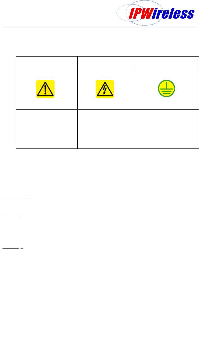
2. Safety Precautions
Table 2-1 : Safety Sumbols
GENERAL WARNING ELECTRICAL HAZARD
GROUND
GENERAL SAFETY
PRECAUTION
VOLTAGE:
Care should be taken when
servicing this area. Misuse or
inappropriate contact with
these areas could result in
physical harm and property
damage
GROUND:
Site for grounding equipment
These cautionary signs are used on the equipment and within this manual. For safety of
personnel and protection of equipment observe these precautions when installing, operating
or servicing the equipment and surrounding areas.
3. General Warnings
Electrical
Power Supply – cord fitted for AC or DC. DO NOT adapt to a different configuration.
Power supply circuits may carry high voltages. Remove rings, watches, and other jewellery
before working with this type of equipment.
Batteries – Certain installation of this equipment require working with lead acid batteries,
batteries present chemical, electric and gaseous hazards. Batteries are not supplied by
IPWireless for the Node B equipment although UPS systems may be coupled with the
device in order to provide back up power in case of power outages.
Physical
Weight – The RF or Digital shelves of the Rack Node B can weigh up to 15kgs (33 pounds)
each depending on configurations. Precautions should be taken, depending on the
installation site conditions, in lifting and general handling the device.
Environmental
There are different precautions to take within each installation situation. Specific
precautions are listed in the installation section for that situation.
Site Location
The NodeB Rack Mount basestation is designed to be installed in restricted access locations
only. The site locations are accessible by suitably trained service/installation personnel only.
Network Connections
The NodeB Rack Mount basestation is NOT suitable for direct connection to Public Switched
Networks. This means that the Node B is NOT suitable for direct connection to TNV circuits.

Node B Rack Mount Installation Guide
Version 0.0.3 Page 7 of 39
4. Overview
Node B is the European Technical Standards Institute’s (ETSI) name for the radio base
station. The basic function of the Node B is to convert 100 Base T packet data into the
UTRAN TD-CDMA air interface used between the Node B and the 3G Modem. The Node B
can be configured to operate in configurations ranging from a single sector or omni mode, up
to a 6 sector arrangement. One Node B is required for each sector of coverage, in the case
of an omni configuration one Node B will be required. The Node B is controlled by an INC
(Integrated network Controller) generally co-located at the site possibly in a separate
cabinet.
The Node B supports both 768 mega chips (10MHz) and 385 mega chips (5MHz) without
any hardware modification.
Scope
This document covers the physical installation and mounting of the Node B Rack Mount in a
rack installation. It contains the specific mounting requirements for installing within a rack ut
does not contain specifications for the rack.
Where the Node B Rack Mount is required to be installed in an outdoor configuration, the
specific requirements for the outdoor enclosure are listed.
The manual does not detail custom or specialised installations or applications.
Additionally, antenna rigging/mounting, lightning protection, tower work, feeder installation /
termination are all considered to be outside the scope of this document.
If in any doubt about the suitability of this document to successfully install at the proposed
location, then please consult IPWireless technical support for assistance.
Node B Rack Mount Installation Guide
Version 0.0.3 Page 8 of 39
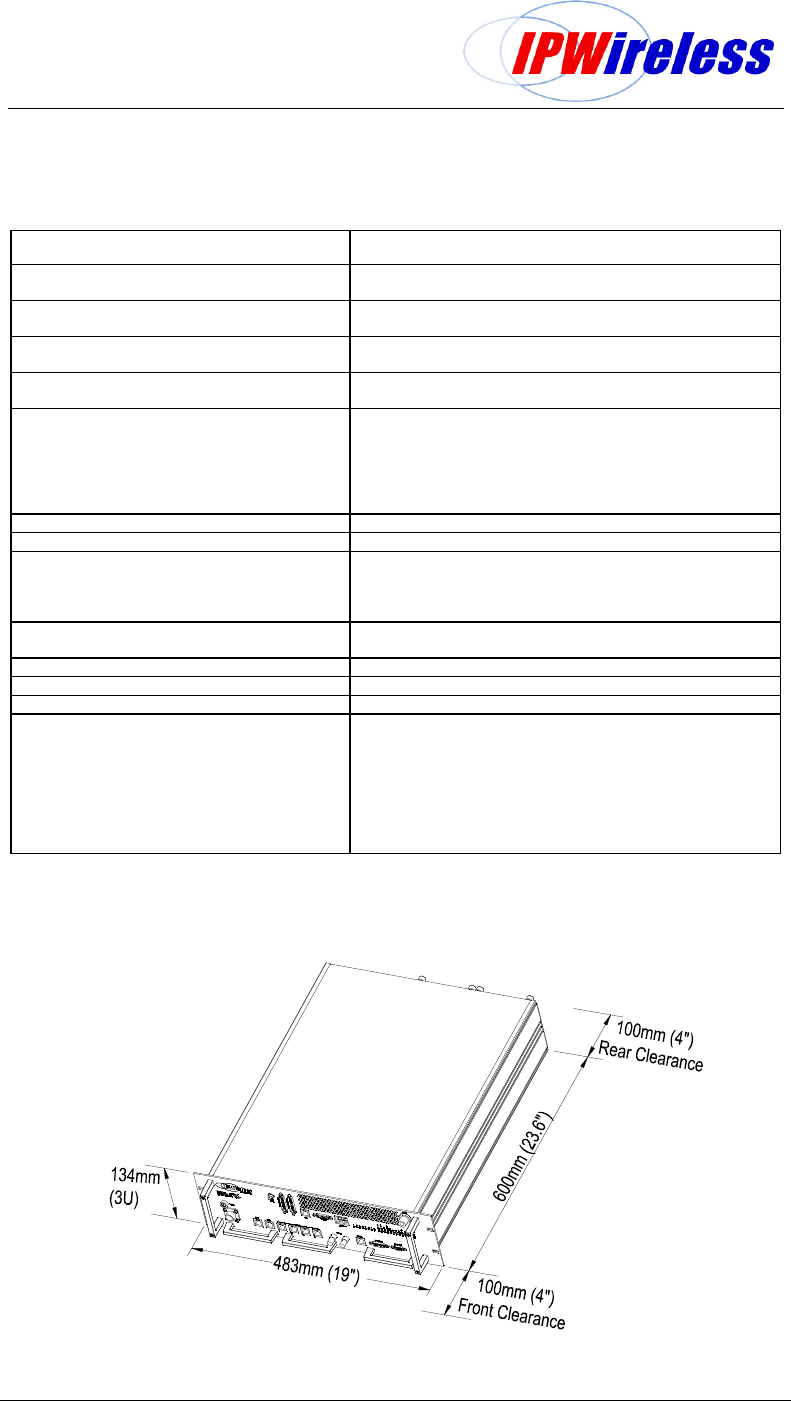
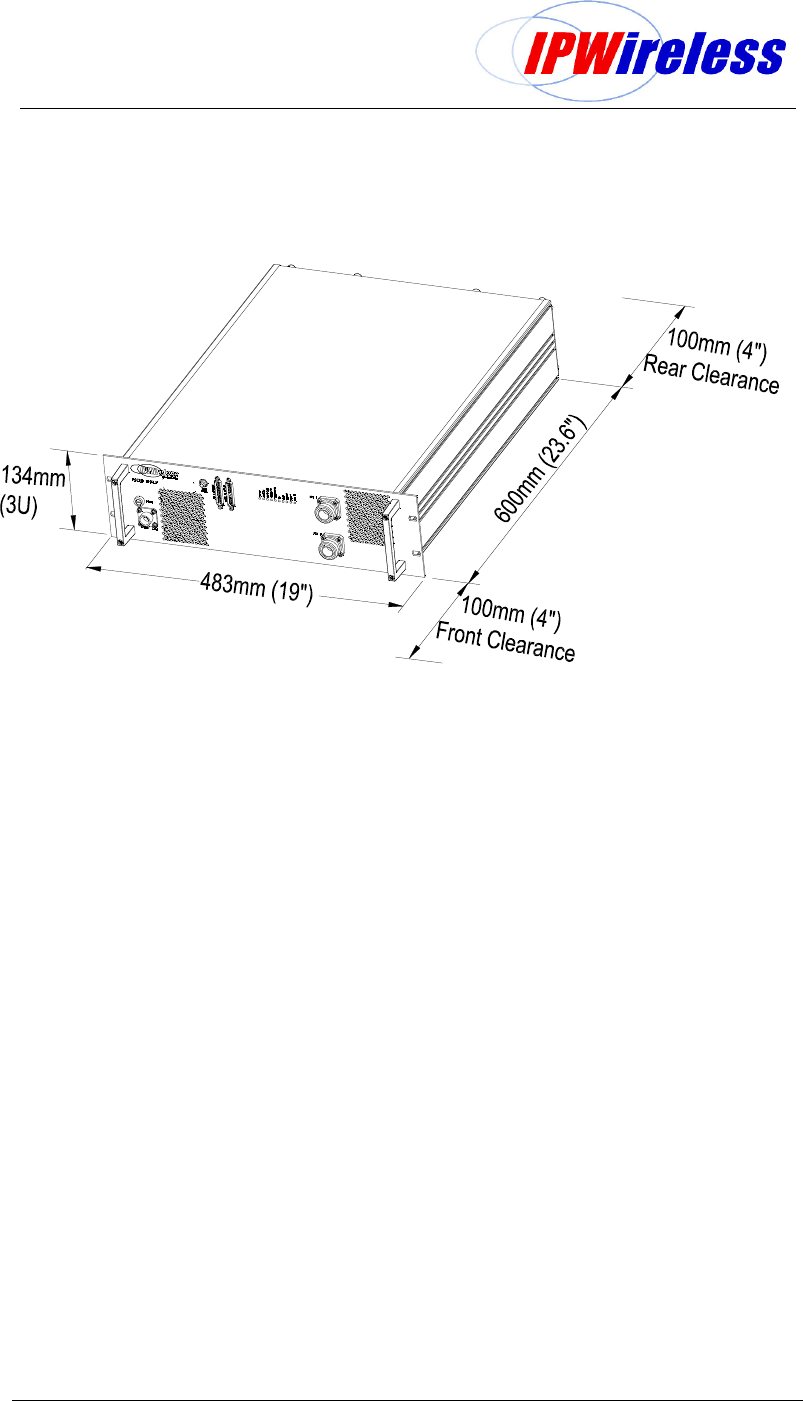
5. General Specifications
Table 5-1 : Specifications
Figure 5-1 : Node B Rack Mount – Digital Shelf Physical Dimensions
Unit Specification
Rack Specifications 19inch Mounting Racks with support shelves
Front Securing
Measurements Digital Shelf: 134 H x 483 W x 600 D mm
RF Shelf: 134 H x 483 W x 600 D mm
Measurements with front handles & cable Digital Shelf: 134 H x 483 W x 650 D mm
RF Shelf: 134 H x 483 W x 650 D mm
Node B Weight Digital Shelf: 12Kgs / 22 lbs
RF Shelf: 20kgs / 33 lbs
Power Consumption
Digial Shelf: 80 Watts max (2Amp Fused)
RF Shelf: 150 Watts max +34dBm – non-TxD (4Amp Fused)
RF Shelf: 310 Watts max +37dBm – non-TxD (7Amp Fused)
RF Shelf: 310 Watts max +34dBm – TxD (7Amp Fused)
RF Shelf: 600 Watts max +37dBm – TxD (12.5Amp Fused)
Note: Fuse Size: ( ¼ x 1 ¼ inch) / (6.3 x 32 mm)
Input Power Nominal -48 V DC
Input Range -36V to -70V DC
Ambient Operational Environment
-5ºC to +45ºC
0 to 95% Relative Humidity- Non-condensing
IP20 – IEC529
No water or Ice precipitation
Cooling Forced Convection – Fan Assisted
Intact front – Exhaust rear
Operating Frequencies MMDS 2500 MHz – 2700 MHz
UMTS 1900MHz – 2100MHz
3400MHz – 3600MHz
Connections - External
Antenna – DIN 7/16 Female
GPS – N-type Female
Power Circular Connectors – cables provided
Ethernet – RJ45
E1/T1 – RJ45
E3/T3 – BNC
Alarm – 15wayD & 9wayD
Earthing – M8 Stud
Node B Rack Mount Installation Guide
Version 0.0.3 Page 9 of 39
Figure 5-2 : Node B Rack Mount – RF Shelf Physical Dimensions
Node B Rack Mount Installation Guide
Version 0.0.3 Page 10 of 39
Table 5-2 : Node B Model Types
TxD
+34dBm
TxD
+37dBm
Non-TxD
+34dBm
Non-TxD
+37dBm
Node B Frequency Model
No
Model
No
1900-1905 MHz N/A N/A N/A N/A
1905-1910 MHz N/A N/A N/A N/A
1910-1915 MHz N/A N/A N/A N/A
1915-1920 MHz N/A N/A N/A N/A
2053-2082 MHz N/A N/A N/A N/A
2010-2015 MHz N/A N/A N/A N/A
2500-2686 MHz EV N/A N/A ET
3480-3580 MHz N/A LB N/A N/A
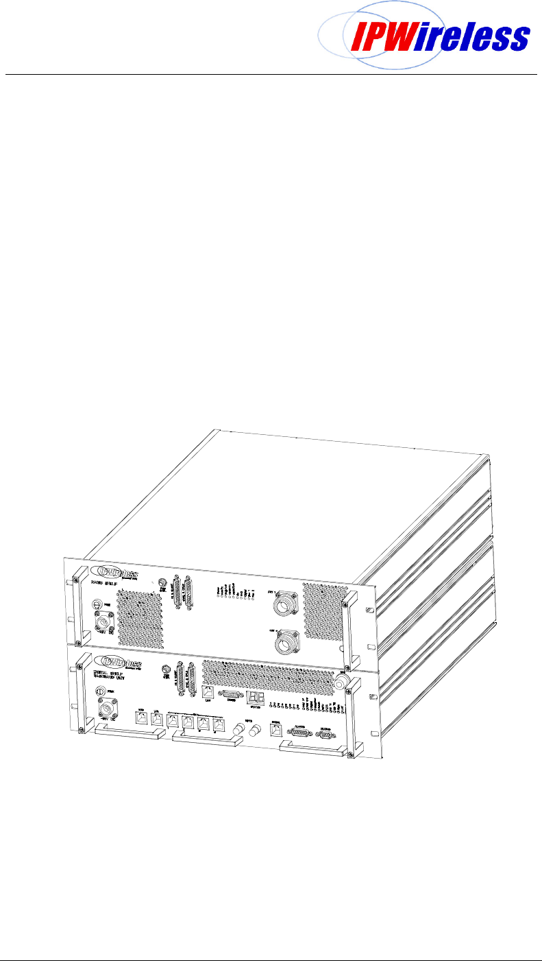
Figure 5-3 : General Description – Front View
Node B Rack Mount Installation Guide
Version 0.0.3 Page 11 of 39
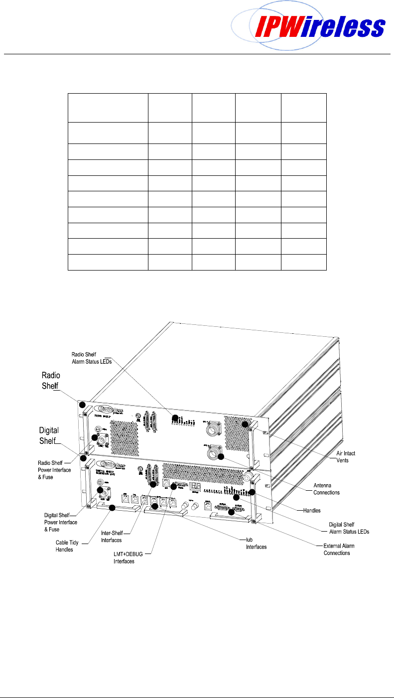
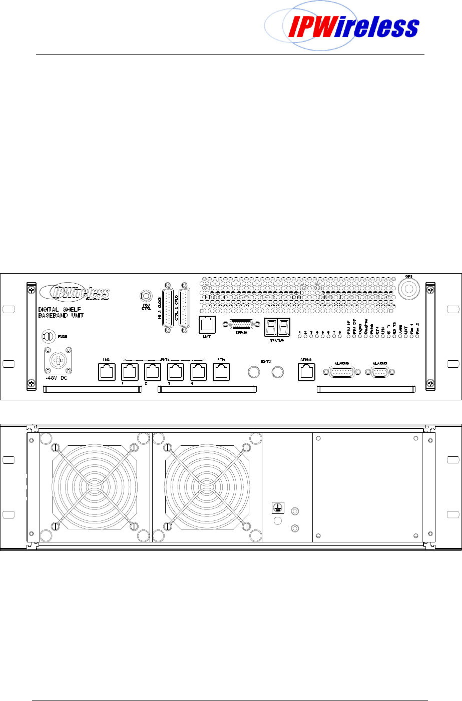
The Digital shelf has the following interfaces on the front
Mains DC supply
Shelf interfaces to RF Shelf
IUB Interfaces – Ethernet, E1, T1, E3 or T3
Alarm Interfaces – input & output
Status - 7 Segment Display
Status – LEDs
LMT & Debug ports
On the rear the earth point and access to the fans.
Figure 5-4 : Digital Shelf Faceplate
Node B Rack Mount Installation Guide
Version 0.0.3 Page 12 of 39
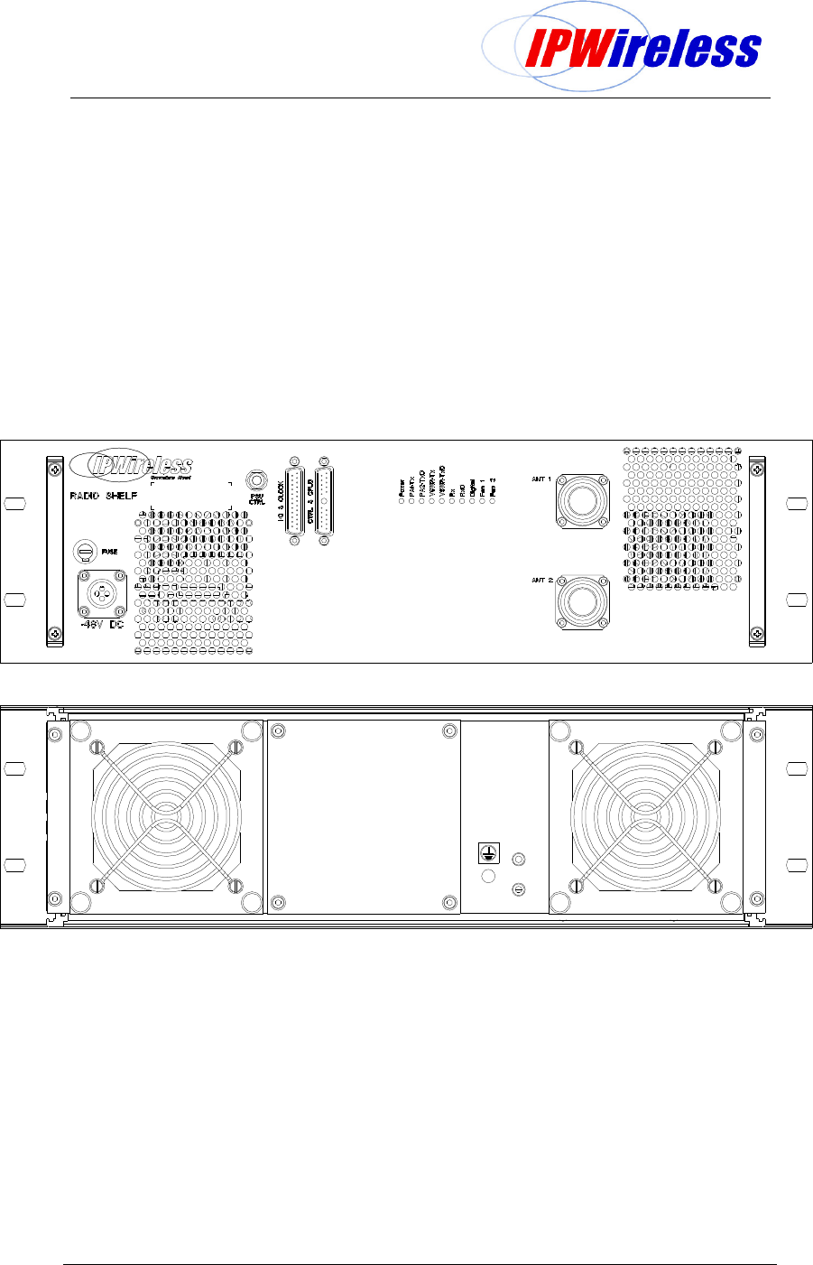
The Radio shelf has the following interfaces.
Mains DC supply
Shelf interfaces to RF Shelf
Antenna Ports
Status – LEDs
On the rear the earth point and access to the fans.
Figure 5-5 : Radio Shelf Faceplate

Node B Rack Mount Installation Guide
Version 0.0.3 Page 13 of 39
6. Installation
This section describes the steps to be followed to physically install the Node B.
Step 1 Pre-Installation
The following are the initial checks that should be carried out to ensure that preparation for
the installation is complete.
For Installation Check Card please see Appendix A at the back of this manual.
1.
Review site construction drawings to determine if site was constructed
according to the drawings.
2.
Review drawings and actual installation to determine location of Node B
installation.
3.
Check availability of electrical, grounding and antenna connections.
4.
Complete site survey.
5.
Check structural strength of mounting rack or frame including shelves/rails to
support Node B total weight of 25Kgs (55lbs) or multiples if a multi-sector
installation.
Node B Rack Mount Installation Guide
Version 0.0.3 Page 14 of 39
Step 2 Parts Shipped & Tools Required
This section reviews the parts, ancillary materials and tools required to install the Node B.
Use this checklist (Table 6-1) to check quantity and quality of parts as they are unpacked: -
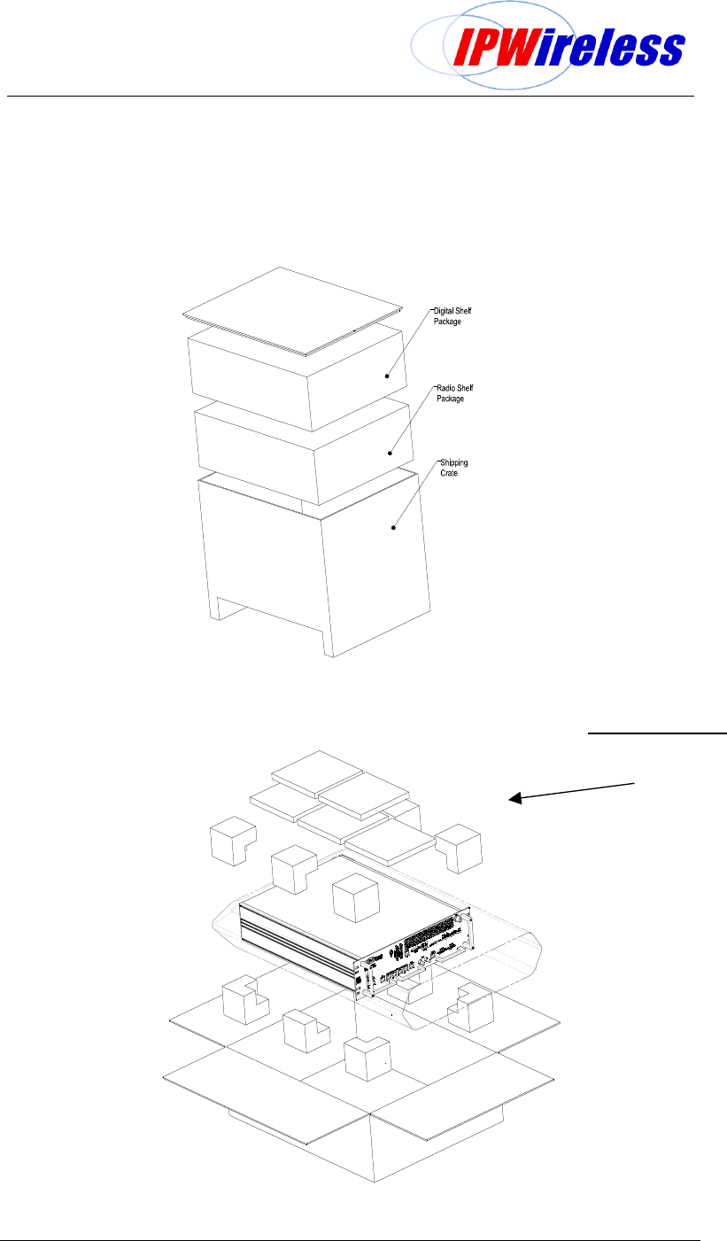
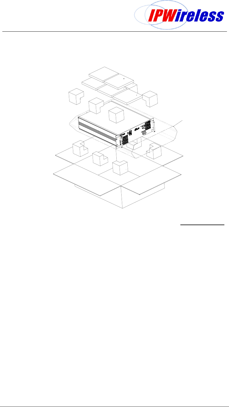
The Node B unit is packaged with the following items, the packing list on the inside top of the
packing shall list these items.
The crate Figure 5-1 contains two cartons the top/first carton is the digital or baseband shelf,
the bottom is the RF or radio shelf. The carton is packed to facilitate the intended sequence
of installation. The figure below shows the sequence of removal from the packing.
Table 6-1 : Packing List
# Description Qty
Digital Shelf Package - contents
1 Node B Digital/Baseband Shelf Unit 1
2 GPS Antenna Kit incl Mounting
contains:
1 x gps antenna
1 x gps antenna mounting
1
3 Alarm Connector Kit
contains:
1 x 15wayD conn+backshell
1 x 9wayD conn+backshell
1
4 Shelf Interface Kit
contains
1 x Baseband cable – 21wayD-hybrid
1 x Control Cable – 25wayD
1 x PSU control cable – 3way
1
5 Power Connection Kit-Digital
contains
1 x power connection – digital
6 Earth Fixing Kit
contains:
1 x M8 Nut
1 x M8 Spring Washer
2 x M8 Plain Washer
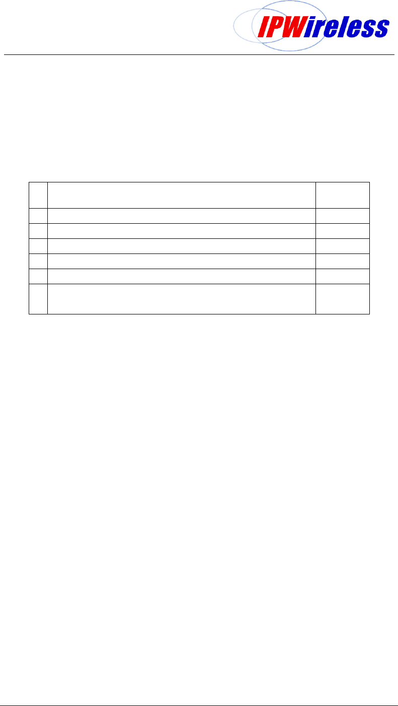
Radio Shelf Package
1 Radio Shelf Unit 1
2 Power Connection Kit-Radio
contains
1 x power connection – radio
1
3 Earth Fixing Kit
contains:
1 x M8 Nut
1 x M8 Spring Washer
2 x M8 Plain Washer
1
Node B Rack Mount Installation Guide
Version 0.0.3 Page 15 of 39
Figure 6-1 : Sales Pack Crate – Digital & Radio Shelf Packages
Figure 6-2 : Digital Shelf Package + Contents
KITS
-
Digital Shelf
1. Earth Kit
2. GPS Kit
3. Alarm Kit
4. Power Connection Kit-Digital
5. Shelf Interface Kit
Node B Rack Mount Installation Guide
Version 0.0.3 Page 16 of 39
Figure 6-3 : Radio Shelf Package + Contents
KITS
-
Radio Shelf
1. Earth Kit
2. Power Connection Kit-Radio

Node B Rack Mount Installation Guide
Version 0.0.3 Page 17 of 39
In addition to standard construction equipment, the following tools and materials should be
available prior to installation:
Table 6-2 : Tools Required
Tools Description
Basic telecommunications tool kit
Includes screwdriver, socket wrenches, etc.
Voltmeter
Fluke meter
Cable Stripper & Crimper
RJ 45 crimper connector
Ethernet cable test set Test for all Ethernet cables
Compass or Handheld GPS with signal indicator
Test for GPS signal at site location
Table 6-3 : Materials Required
Material
Description
CAT5 - 4 pair, double screened cable, recommended
Alcatel LANmark-5 F
2
TP or equivalent
IUB / LMT / T1 / E1 Cable
RJ45 Connectors
IUB / LMT / T1 / E1 Connections
CAT5 - 4 pair, double screened cable, recommended
Alcatel LANmark-5 F
2
TP or equivalent
Alarm distribution cable
10 mm
2
maximum Ground cable Grounding termination
M8 ring terminal
Grounding termination
BNC Right Angle Connectors Connectors for E3/T3 Connections
RG59 B/U-LSF and UV stabilised or equivalent Cable for E3/T3 Connections
Rack mounting 8 off Cage nuts + Screws – note these
are required to secure the shelves to the rack
typically M6 Thread screws, washers & rack
cage nuts
Rack/Cabinet or Enclosure
Installation and/or site specific
Shelf Supports or rails
Specific to rack/cabinet or enclosure
DIN 7/16 antenna connections
Connectors specific to antenna cable chosen
Antenna Cable
Site specific selection
Node B Rack Mount Installation Guide
Version 0.0.3 Page 18 of 39
Step 3 Site Preparations for Node B Installation
The section specifies the facilities that need to be available at the site prior to installation. The
table below is a site checklist that should be completed prior to installation.
It is assumed that the site has already been selected from RF network planning and that site
acquisition or permission has been granted.
Table 6-4 : Site Preparation Checklist
# Facility Complete
Yes/No
1 Mains power supply –48Vdc
2 Availability of suitable Ethernet, E1, T1, E3 or T3 Interfaces
3 connections and trunking/conduits for interfaces
4 Suitable earth
5 Rack or cabinet suitable to mount the NodeB
6 Clearance around the NodeB for cable entry and cooling
- see figure below
Assumptions
It is assumed that prior to Node B installation all civil, electrical distribution, structured
cabling termination work has been completed.
Additionally, all antenna rigging, feeder runs and terminations, associated lightning
protection and earthing, has been done, with certification for safety / compliance issued as
required by local regulations.
It is also strongly recommended that all VSWR plots of the feeder / antenna installations
should be available for inspection.
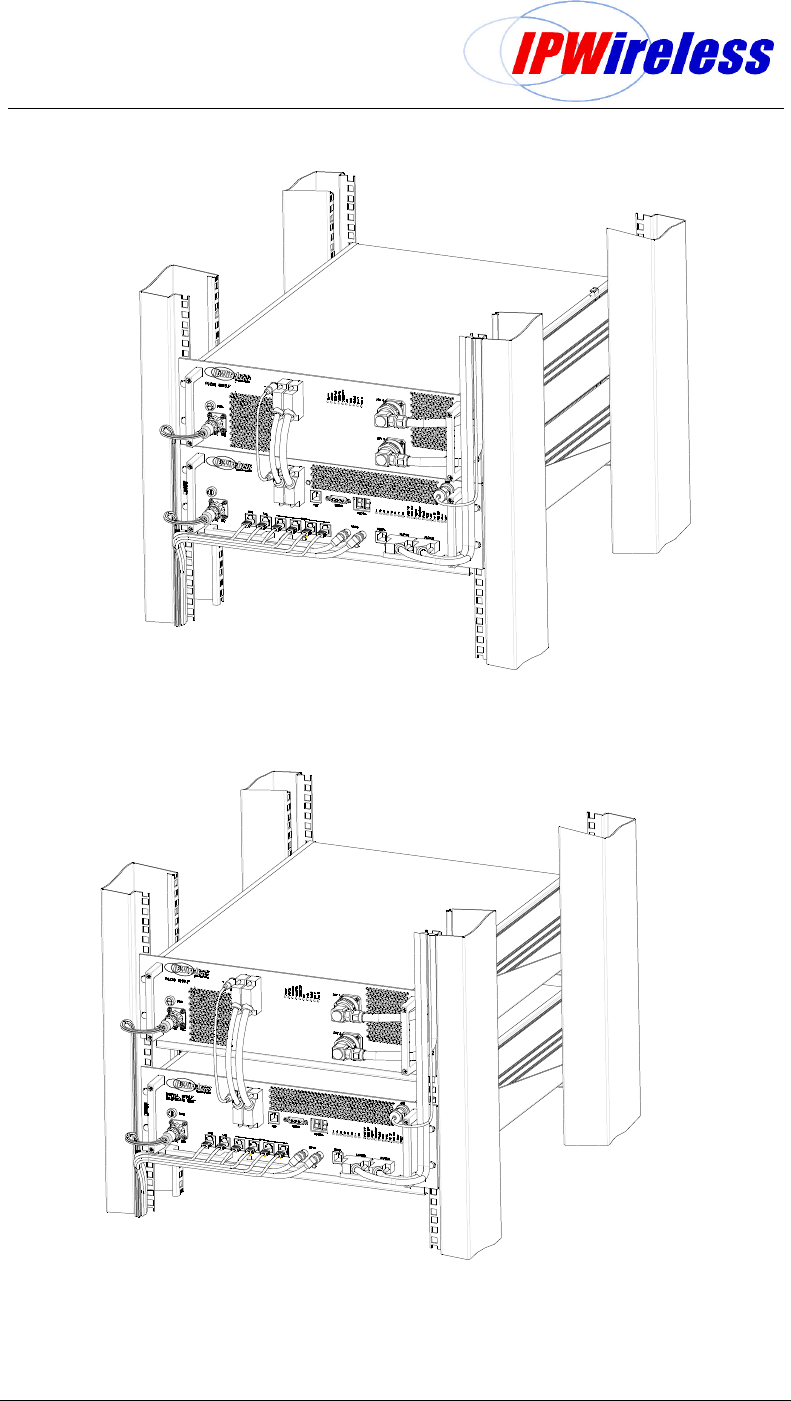
Positioning the Node B with a rack or cabinet
The digital and RF shelves of the rack mount may be mounted on a single shelf/shelf
support as a pair (Figure 6-4) or can be mounted into the rack on separate shelves or
shelf supports (Figure 6-5).
The RF shelf needs to be on the top with the digital shelf beneath. The maximum vertical
distance between the shelves shall be not more than 1U (44mm or 1 ¾”).
Selection of a suitable position for the Node B shall be done by surveying possible sites
with regard to the availability of facilities i.e. power, relative position to the INC and
consulting the site plans.
The Node B directly connected to the INC should be sited not more than 100m from the
INC using Shielded Category 5 Ethernet cable as specified.
Care should be taken to position the Node B for easy front and rear access.
The Node B will need to be connected near the feeder terminations and earthing points
as provided on site.
Where the Node B is installed using a microwave link ensure that the microwave link can
support the Ethernet requirements for the IUB interface i.e. 10 or 100 Mbps / full / half
duplex as the Node B and INC may need to be configured manually in order to support
this configuration.
Node B Rack Mount Installation Guide
Version 0.0.3 Page 19 of 39
Figure 6-4 : Node B Rack Mount – Single Support Shelf (all cables shown)
Figure 6-5 : Node B Rack Mount – Double Support Shelf (all cables shown)

Node B Rack Mount Installation Guide
Version 0.0.3 Page 20 of 39
General Considerations
The following consideration and checks are applicable to all mounting types :-
The NodeB rack mount is designed for indoor use only refer to Table 5-1.
Review the GPS installation guidelines (step 12) to ensure that the location will allow
proper operation of the Node B GPS remote antenna. i.e. a Southern Exposure is
required for outside installations (Northern Hemisphere), a GPS repeater may be
necessary in areas where the active GPS antenna cannot reach.
There should be a minimum clearance of 100mm in front and behind the Node B rack
mount (Figure 5-1 & Figure 5-2) for cable routing, air intake/exhaust and access to fans
at the rear.
Ensure that the rack or cabinet is sufficiently strong to support the Node B or multiples.
The Node B requires un-restricted airflow front for air inlet to the rear for air exhaust.