General Dynamics Broand NODEBDZ1 Wireless Broadband Base Station User Manual Part 2
General Dynamics Broadband, Inc. Wireless Broadband Base Station Users Manual Part 2
Contents
- 1. User Manual Part 1
- 2. Users Manual Part 2
Users Manual Part 2
Node B Rack Mount Installation Guide
Version 0.0.3 Page 21 of 39
Step 4 Mounting Installations
This section explains how to mount the Node B Rack Mount shelves into racks.
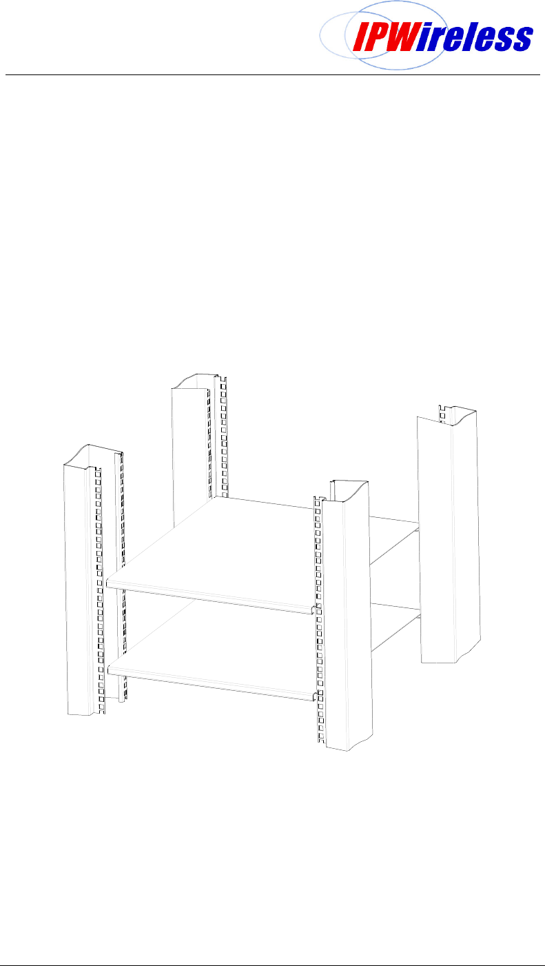
Mounting Rack
The figure below illustrates the 19inch mounting rack plus support shelves, some racks or
cabinets can use support rails. This construction can be within an enclosure or cabinet.
The support shelves or rails are specific to the rack, enclosure or cabinet being installed,
thus their specification shall be part of same selection.
Figure 6-6 : Mounting Rack + Support Shelves/Rails
Node B Rack Mount Installation Guide
Version 0.0.3 Page 22 of 39
Precautions
The following precautions and checks are applicable to all mounting types:-
Connectors have been manufactured to fit their specific cables and funcition. Do not
modify or force connectors.
Check Site Plans for engineering approval.
Ensure that good ground resistance is available at the installation site (10)
Where installed in an outdoor enclosure attention should be paid to cooling and
water+dust sealing prevention refer to Table 5-1.
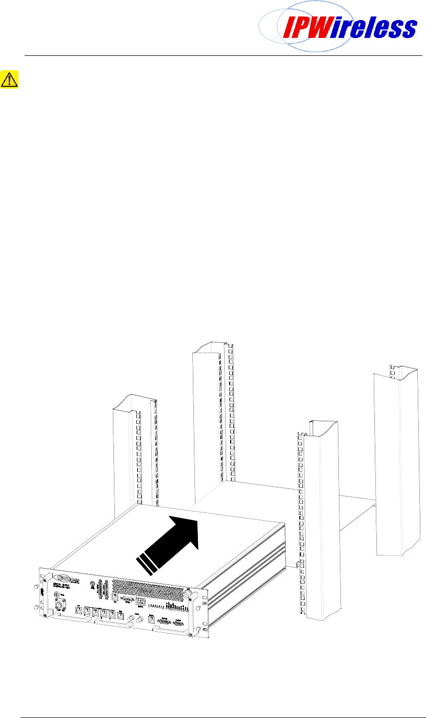
Rack Mounting – Installing Digital Shelf
Ensure the shelf or shelf supports are secure, then insert the digital shelf into the rack and
secure from the front.
Notes:
If there is no rear access it may be required to make the ground connection prior to
inserting the shelf into the rack.
Where additional securing is required at the rear this shall require custom brackets
depending on the rack specifications/construction.
Figure 6-7: Installing Digital Shelf
Node B Rack Mount Installation Guide
Version 0.0.3 Page 23 of 39
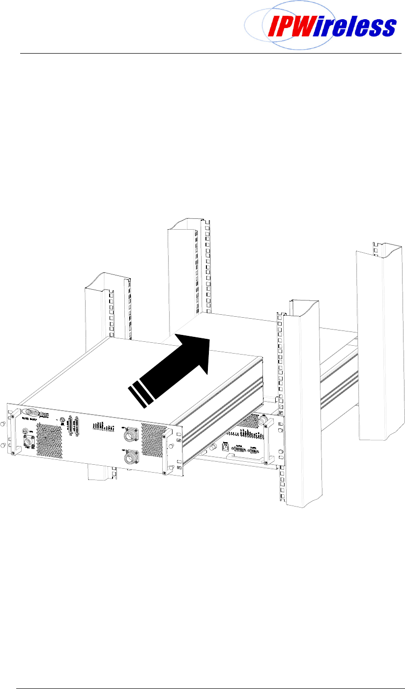
Rack Mounting – Installing Radio Shelf
Ensure the shelf or shelf supports are secure, then insert the radio shelf into the rack and
secure from the front.
Notes:
If there is no rear access it may be required to make the ground connection prior to
inserting the shelf into the rack.
Where additional securing is required at the rear this shall require custom brackets
depending on the rack specifications/construction.
Figure 6-8 : Installing Radio Shelf
Node B Rack Mount Installation Guide
Version 0.0.3 Page 24 of 39
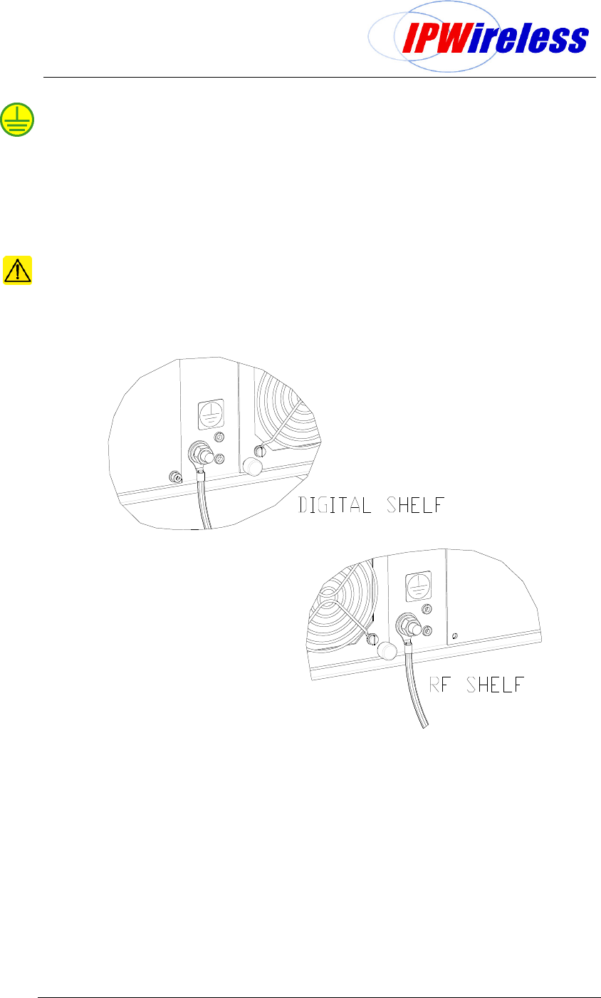
Step 5 Ground Installation
The main Node B ground cable shall use a minimum #2 AWG (Diameter 6.6mm or CSA
33mm2) stranded wire or equivalent earth braid.
The ground cable is terminated on the rear of both shelves of the Node B Rack Mount using
terminal that shall fit the M8 (7/16”) stud on the rear of each shelf.
The grounding wire is terminated onto the site grounding ring.
It should be noted that each site shall be designed for specific site, country or local
installation requirements.
CAUTION: Ensure that the earth braid or cable is bonded to a common earth with
equipment that is co-located with the Node B.
Figure 6-9 : Earth Connection on the rear of each shelf
Node B Rack Mount Installation Guide
Version 0.0.3 Page 25 of 39
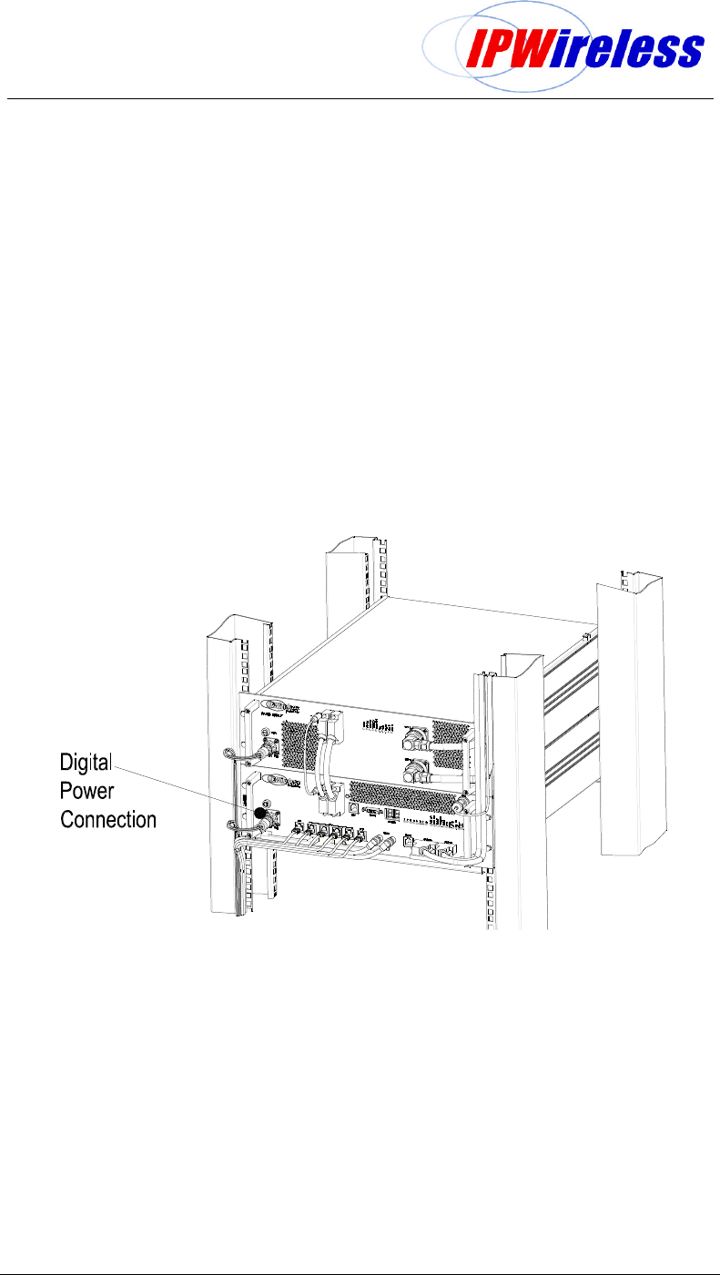
Step 6 DC Power Connection-Digital
The power supply input must be a nominal -48Vdc input, refer to Table 5-1.
The connection of the mains to DC supply is via the cable provided as part of the digital shelf
package.
The provided cable assembly has 3 metres of cable with a connector to provide connection
to the digital shelf. The tail ends of the cable are stripped and must be terminated to a
permanent connection junction/terminal block. The length of the cable may be shortened to
facilitate.
Notes:
Only the cable provided with the digital shelf should be used.
The connector is keyed to prevent wrong insertion.
Figure 6-10 : Power Connection to the digital shelf
Node B Rack Mount Installation Guide
Version 0.0.3 Page 26 of 39
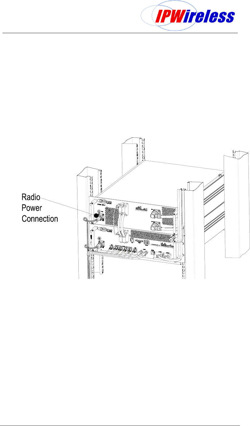
Step 7 DC Power Connection-Radio
The power supply input must be a nominal -48Vdc input, refer to Table 5-1
The connection of the mains to DC supply is via the cable provided as part of the radio shelf
package.
The provided cable assembly has 3 metres of cable with a connector to provide connection
to the radio shelf. The tail ends of the cable are stripped and must be terminated to a
permanent connection junction/terminal block. The length of the cable may be shortened to
facilitate.
Note: Only the cable provided with the radio shelf should be used.
Figure 6-11 : Power Connection to the radio shelf
Node B Rack Mount Installation Guide
Version 0.0.3 Page 27 of 39
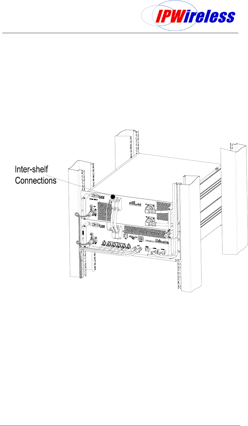
Step 8 Inter-Shelf Connections
The digital shelf is supplied with the shelf interface kit that contains the following items
• I/Q interface cable – 21wayD-hybrid
• Control interface cabe – 25wayD
• PSU control cable – 3way
The figure below illustrates the connection of each of these cables between the digital and
radio shelf.
Figure 6-12: Interface Cable Connection
Node B Rack Mount Installation Guide
Version 0.0.3 Page 28 of 39
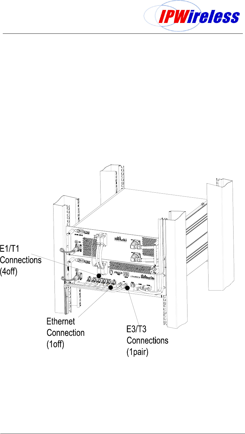
Step 9 Backhaul Connections (Iub) to INC
The Digital Shelf faceplate contains the backhaul connections. The installation can be
selected from the following interfaces
100BaseT
E3/T3
E1/T1
The connections are labeled and shown in the figure below.
Note: If the Node B is in not in the same site location as the serving INC, there must be no
greater than a 5 millisecond delay on the backhaul connection. This can be provided by
microwave or land based facilities with a reliability rate of 99.9995%.
Figure 6-13 : Backhaul Connections
Node B Rack Mount Installation Guide
Version 0.0.3 Page 29 of 39
100BaseT Connection - (Eth)
Terminate the Ethernet cables with RJ45 connectors and the cables may be secured to the
brackets on the face of the Digital Shelf (
Figure 6-13
). Test the continuity for the Ethernet cables
with test equipment consisting of a main and a remote unit.
The termination for these interfaces is specified within the datasheets for the interfaces. The
specification for both cables should be CAT5 - 4 pair, screened cable, recommended Alcatel
LANmark-5 F2TP or equivalent.
Notes:
Points to remember when installing Category 5 cables for the Node B 100Base T
Ethernet Backhaul.
1. Do not kink the cable as the pairs are twisted to support 100Mhz operation and splitting the
pairs could reduce the performance of the cable.
2.
When installing the RJ45 plugs onto the cable ensure pairs are untwisted to the minimum
and that the cable sheath is clamped within the connector. Again this is to ensure the
performance of the cable is not reduced.
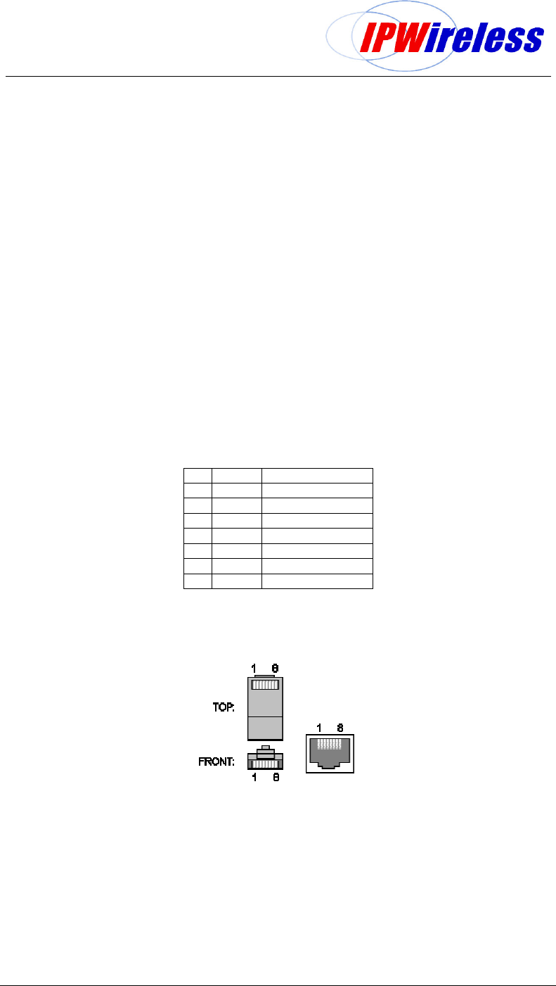
The pin-outs for the external Ethernet interfaces are given in the following table & figure.
Source: http://www.dcbnet.com/notes/9611t1.html
Table 6-5 : Ethernet Pin-outs using RJ45
1 RX + White w/Green
2 RX - Green
3 TX + White w/Orange
4 Blue
5 White w/Blue
6 TX - Orange
7 White w/Brown
8 Brown
Figure 6-14 : Ethernet Pin-outs using RJ45
Node B Rack Mount Installation Guide
Version 0.0.3 Page 30 of 39
E3/T3 Connections – (Tx + Rx)
Terminate the E3/T3 cables with BNC connectors and the cables may be secured to the brackets
on the face of the Digital Shelf (
Figure 6-13).
Test the continuity for the E3/T3 cables with test
equipment consisting of a main and a remote unit.
The termination for these interfaces is specified within the datasheets for the interfaces. The
specification for both cables should be 75.
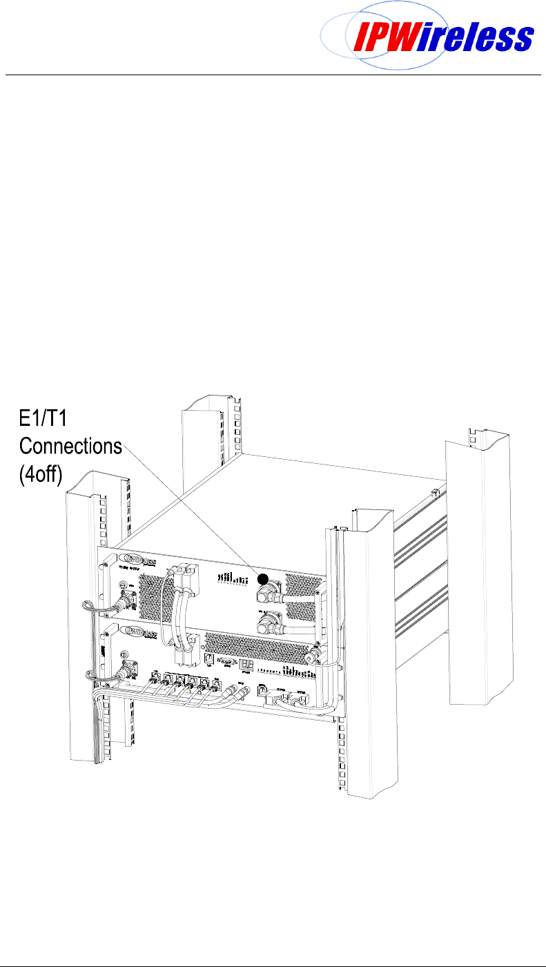
E1/T1 Connections – (1 to 4)
Terminate the E1/T1 cables with RJ45 connectors and the cables may be secured to the brackets
on the face of the Digital Shelf (
Figure 6-13
).
Test the continuity for the E1/T1 cables with test equipment consisting of a main and a remote
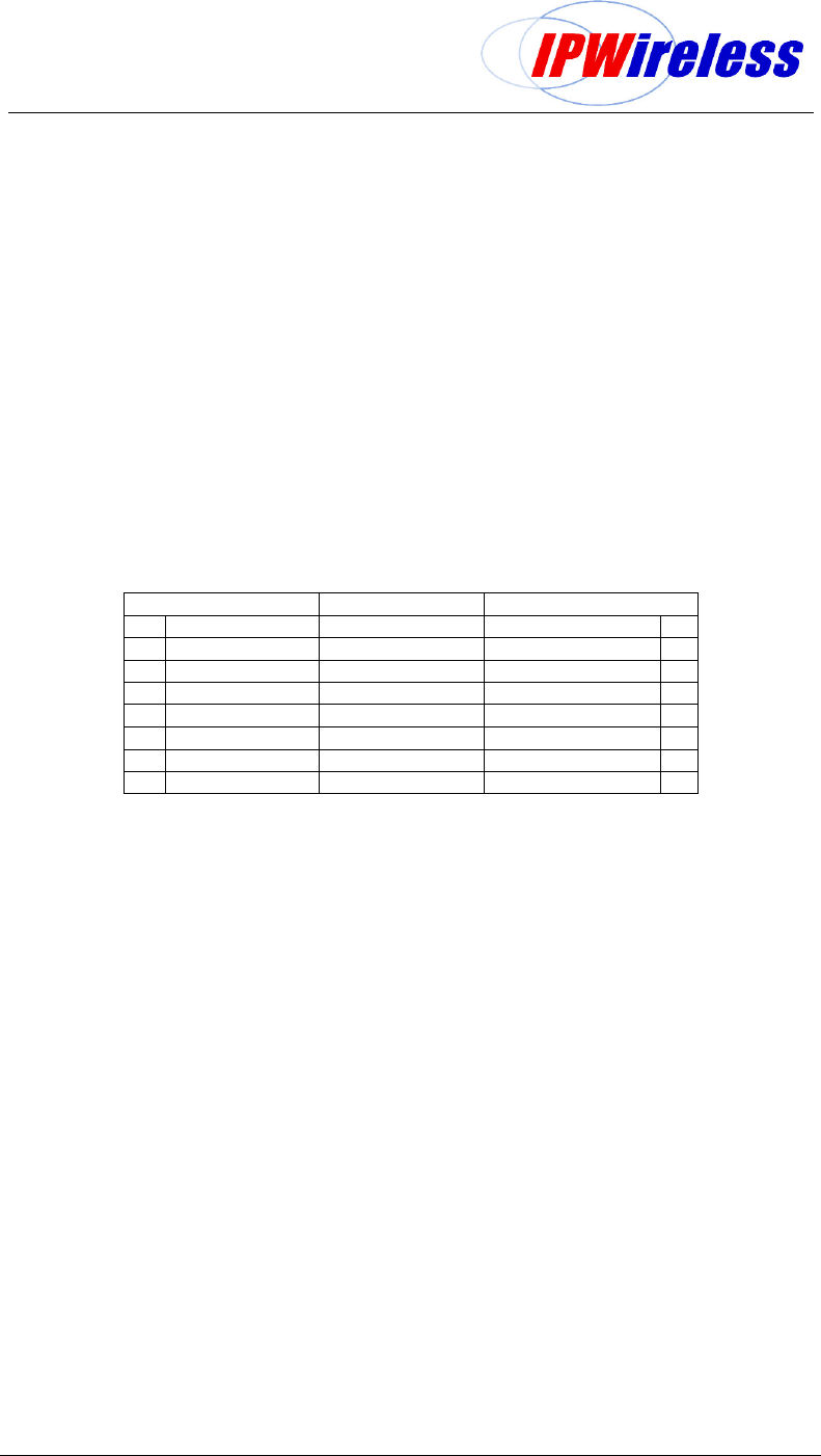
unit. The pinouts for this interface are shown in the table below.
The termination for these interfaces is specified within the datasheets for the interfaces. The
specification for both cables should be CAT5 - 4 pair, screened cable, recommended Alcatel
LANmark-5 F2TP or equivalent.
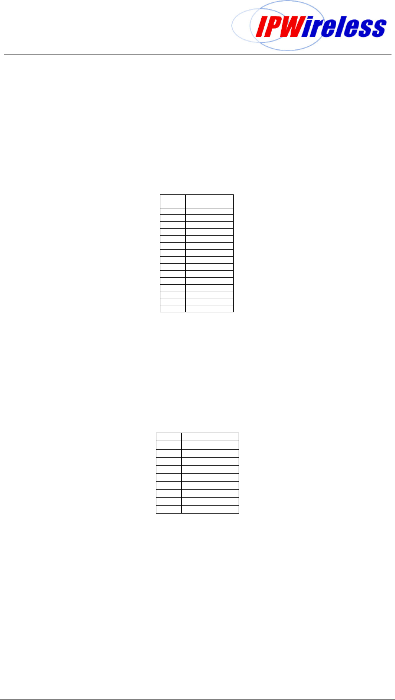
Table 6-6 : T1/E1 Pin-outs
T1 Pinouts Cable E1 Pinouts
1 Rx (ring) White w/Green Rx (ring) 1
2 Rx (tip) Green Rx (tip) 2
3 Not used White w/Orange Not used 3
4 Tx (ring) Blue Tx (ring) 4
5 Tx (tip) White w/Blue Tx (tip) 5
6 Not used Orange Not used 6
7 Not used White w/Brown Not used 7
8 Not used Brown Not used 8
Node B Rack Mount Installation Guide
Version 0.0.3 Page 31 of 39
Step 10 Antenna Cabling - Installation
Antennas and coaxial cable should be available at the site, and are part of the construction
checklist and general assumptions.
Two antennae per Node B Radio Shelf are optimum, allowing receiver diversity and transmit
diversity (note: if option fitted), therefore two coaxial cables per Node B are needed. Diversity can
be via polarization, in which case two feeder runs to the same antenna are needed, feeding
oppositely polarised sectors in the same physical enclosure.
Cables should be properly marked to indicate what antenna the coaxial cables are to be
connected to the Node B serving the sector or area.
In the case where only one feeder / antenna is being used, this must be connected to the top
connector when viewed from the front of the Node B.
The following installation describes the position of the antenna ports and designations.
Figure 6-15 : Antenna Connections & Routing
Node B Rack Mount Installation Guide
Version 0.0.3 Page 32 of 39
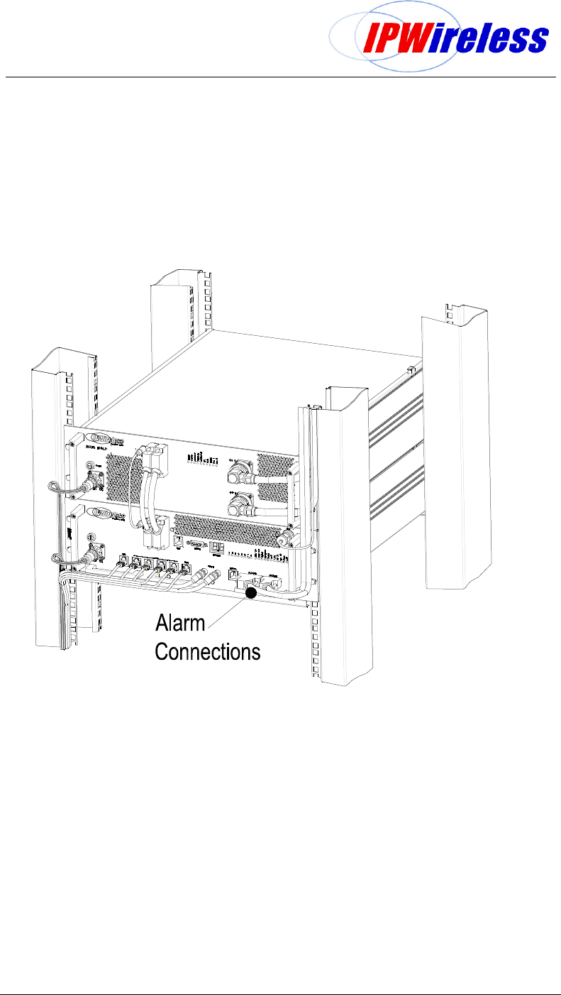
Step 11 Alarm Connections
If local alarms are to be utilised two Dtype connectors are been provided on the Node B
digital shelf. The specifications for those interface requirements are below:-
The maximum input voltage is restricted to 39V for a 500A 8/20 uS pulse, with a minimum
working voltage of 18V. All six input circuits are the same.
Figure 6-16 : Alarm Outputs & Inputs
Node B Rack Mount Installation Guide
Version 0.0.3 Page 33 of 39
Alarm Inputs
The 6 external alarm inputs are connected via the 15wayD female type located on the right
hand side of the digital shelf.
The external alarm inputs are opto-isolated current loops. The voltage and currents shall be
supplied by the external source.
The pin-out for the alarm inputs are shown in the table below.
Table 6-7 : Alarm Inputs
Pin
#
Signal
1 ALARM_IN_A0
2 ALARM_IN_B0
3 ALARM_IN_A1
4 ALARM_IN_B1
5 ALARM_IN_A2
6 ALARM_IN_B2
7 ALARM_IN_A3
8 ALARM_IN_B3
9 Earth
10 ALARM_IN_A4
11 ALARM_IN_B4
12 ALARM_IN_A5
13 ALARM_IN_B5
14 Earth
15 Earth
Alarm Outputs
The external alarm outputs are connected via the 9wayD female located on the right hand
side of the digital shelf.
The external alarm outputs shall be isolated normally-open relay contacts capable of
switching 100mA DC.
The pin-out for the alarm inputs are shown in the table below.
Table 6-8 : Alarm Outputs
Pin Signal
1 ALARM_OUT0+
2 ALARM_OUT0-
3 Earth
4 ALARM_OUT0+
5 ALARM_OUT0-
6 Earth
7 Earth
8 Earth
9 Earth
Node B Rack Mount Installation Guide
Version 0.0.3 Page 34 of 39
Step 12 GPS Installation & Operation
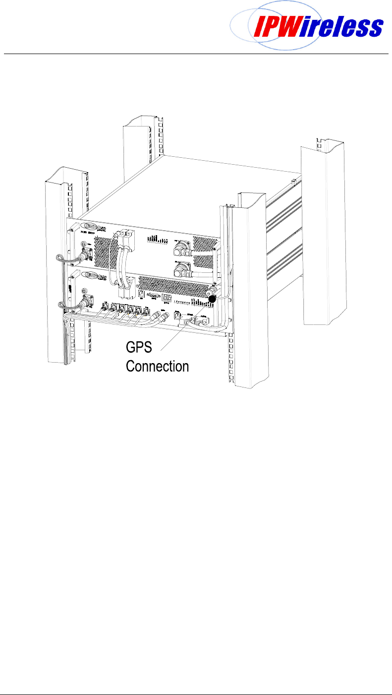
The Node B has an external/remote GPS antenna and receiver. The connection for the
antenna (N-Type) is located on the Digital Shelf, Figure 6-17.
The GPS timing signal is used by the Node B for the TDD frame timing, so that all Node B's
in a network are synchronized. The GPS signal is also used by the master oscillator for a
frequency reference. The Node B can operate for two hours after a loss of GPS timing but a
gradual drift of the frame timing will result in system interference and a loss of Node B
selection / reselection capability.
A suitable Node B GPS antenna is shipped with every Node B. This antenna should be used
with a maximum of 15 metres cable of RG6 type cable plus male N-type connectors at each
end. For longer runs, the cable losses will affect signal strength and could impede GPS
signal performance.
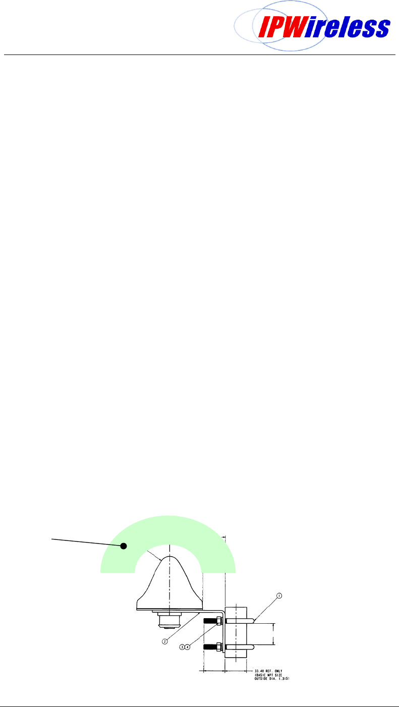
For proper operation of the GPS receiver, the Node B GPS Antenna must have a clear
southern view of the sky. A site survey should be done before Node B installation to verify
that the Node B installation location is suitable for GPS reception.
A simple survey method is to take a handheld GPS receiver to the site and verify that GPS
lock is obtained in the location of the Node B installation. The handheld GPS should be able
to obtain a "locked" condition within 2 minutes of power-on, and should be able to see a
minimum of 4 satellites at all times.
The GPS receiver, integral to the Node B Digital shelf, is automatically enabled when the
Node B is powered and there are no adjustments or settings to be made by the user.
Note: When the Node B installation is on or near a tower or building wall, the GPS survey
should replicate the configuration.
When tower space is at a premium, or when long cable runs are involved, it may be
preferable to use a single GPS antenna to feed multiple Node Bs. It is possible to use one
GPS antenna with up to three units, providing that a passive splitter is used.
Caution: It is essential that in a ‘single GPS antenna supporting multi-Node B’ installation
only one of the Node B’s is designated and configured to supply the GPS antenna with +5V
via the GPS antenna cable as in a standard single installation.
The remaining subordinate Node Bs are provided their GPS signal through a DC block
device. Failure to do this may result in damage to the Node B. It should also be noted that in
the event of power failure to the DC supplying Node B, GPS reception to all Node B’s will be
affected.
Figure 6-17 : GPS Antenna
GPS Antenna
Field of Vision No
Obstructions
Node B Rack Mount Installation Guide
Version 0.0.3 Page 35 of 39
Figure 6-18 : GPS Antenna Connection

Node B Rack Mount Installation Guide
Version 0.0.3 Page 36 of 39
7. APPENDIX
Appendix A - Installation Check Card
Step Action Complete Comment Page
1
Perform pre-installation site check
2
Parts shipped/tools required
3
Site Preparation
4
Mounting rack/cabinet installation
5
Grounding installation
6
DC Power Connection-Digital Shelf
7
DC Power Connection-Radio Shelf
8 Inter-shelf interface connections
9
Backhaul Connections to INC
10
Antennas Cabling - Installation
11
Alarm Connections
12
GPS Installation & Operation

Node B Rack Mount Installation Guide
Version 0.0.3 Page 37 of 39
Appendix B - Glossary
GLOSSARY
ADC Analog to Digital Converter
ARP Address Resolution Protocol
BTS Base Transceiver Station
DAC Digital to Analog Converter
Downlink From Network to the User Equipment
DSCH Downlink Shared Channel
ESD Electro Static Discharge
EM Element Manager
EIA Engineering Industry Association
Ethernet 10BaseT or 100baseT
ETSI European Telecommunications Standardization Institute
FCC Federal Communication Commission
FPGA Field Programmable Gate Array
GPS Global Positioning System
HTTP Hyper-Text Transfer Protocol
INC Integrated Network Controller
IP Internet Protocol
ISP Internet Service Provider
ITFS Instructional Television Fi xed Service
IUB Interface Between the INC & NodeB
LMT Local Maintenance Terminal
LNA Low Noise Amplifier
MCP Multimedia Communications Port
MAC Media Access Control
Mcps Mega Chips per Second
MMDS Multichannel Multipoint Distribution Service
MSPS Mega Samples Per Second
MTU Maximum Transmission Unit
Node B A UMTS Radio Base Station
PDU Protocol Data Unit
PLL Phase Locked Loop
QPSK Quadrature Phase Shift Keying
RAM Random Access Memory
RLC Radio Link Control
SRAM Static RAM
T1/E1 1536kbps/ 2048Kbps pipe
T3/E3 45Mbps or 34Mbps
UE User Equipment
UMTS Universal Mobile Telecommunications System

Node B Rack Mount Installation Guide
Version 0.0.3 Page 38 of 39
GLOSSARY
Uplink From User Equipment to the Network
USB Universal Serial Bus
USCH Uplink Shared Channel
UPS Uninterruptible Power Supply Unit
UTRAN UMTS Terrestrial Radio Access Network
VSWR Voltage Standing wave ratio
VCXO Voltage Controlled Crystal Oscillator

Node B Rack Mount Installation Guide
Version 0.0.3 Page 39 of 39
END OF DOCUMENT