General Dynamics Broand USBSTKAPJ Wireless Broadband Modem User Manual External Antenna
General Dynamics Broadband, Inc. Wireless Broadband Modem External Antenna
Contents
- 1. LTE USB Stick User Guide
- 2. USB Stick LTE RF Exposure Addendum
- 3. User Manual External Antenna
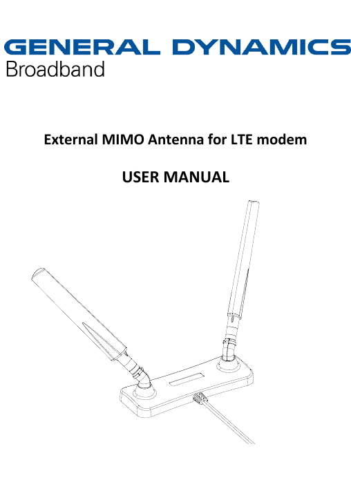
User Manual External Antenna