General Dynamics Broand USBSTKAPJ Wireless Broadband Modem User Manual External Antenna
General Dynamics Broadband, Inc. Wireless Broadband Modem External Antenna
Contents
- 1. LTE USB Stick User Guide
- 2. USB Stick LTE RF Exposure Addendum
- 3. User Manual External Antenna
User Manual External Antenna
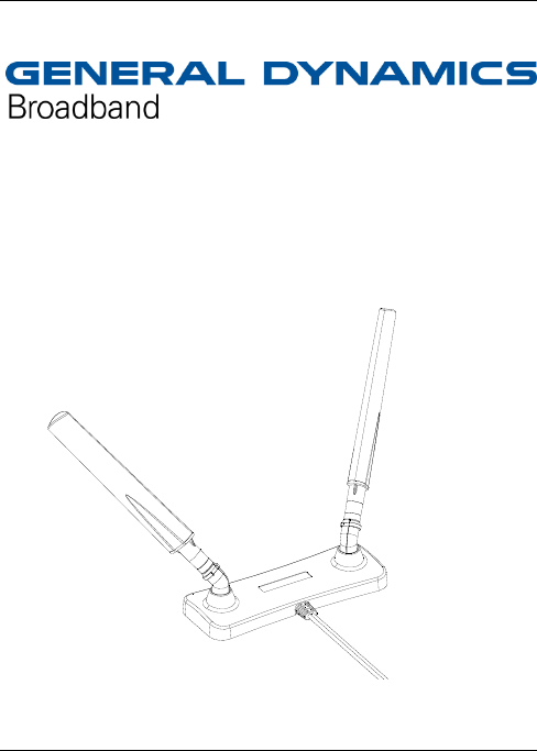
External MIMO Antenna for LTE modem
USER MANUAL

IPW-2754 Iss.1 2
General Information
In order to improve the data transmission parameters, a special external
antenna (model: LTE-ODUP001-IPW) has been designed to interwork with
the LTE USB-stick modem. The antenna base has a build-in magnet which
facilitates the installation on metal surfaces e.g. metal windowsills. With
the fixings provided it is also possible to secure the antenna to an internal
or external walls.
The antenna is equipped with a 3 meter cable terminated with the RF
connector for connecting to the modem.
Specification
Frequency range 690-750 MHz
1710-1880 MHz
2500-2700 MHz
Gain: max 2dBi
Polarisation Linear, +/- 45°
Output power max 4W
Operating temperature -20°C to +55°C
Cable Length 3 m
IPW-2754 Iss.1 3
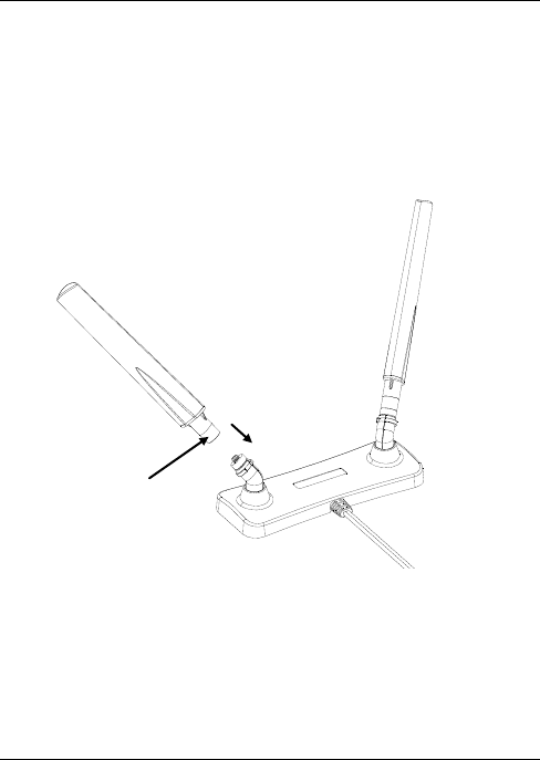
Installation instructions
Before connecting to the modem, two antenna arms shall be connected
to the base. After attaching the antenna arms, they are positioned at a
fixed factory tilt angle (i.e. approx. 45 degrees relative to the base).
Insert antenna
arm onto base
connector
Secure arm
using knurled
connection
IPW-2754 Iss.1 4
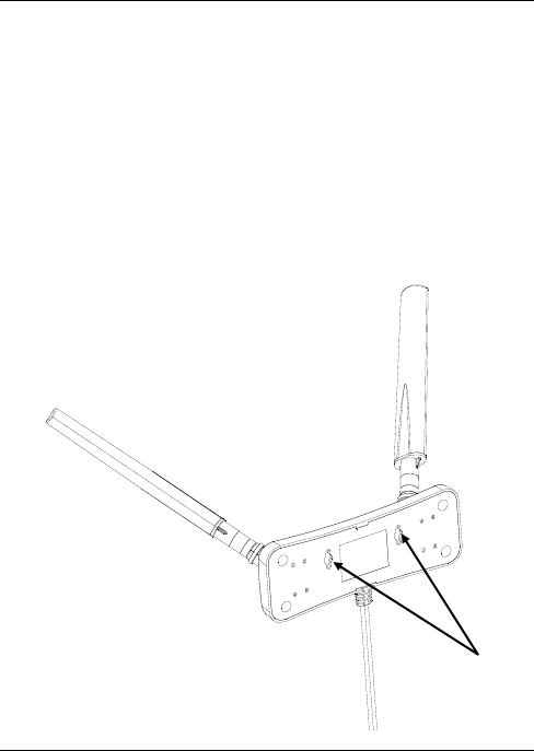
Installation on the wall
Screw the supplied screws into the wall in such a way that the
screws match the ‘keyholes’ in the base so that after
installation the antenna is fastened in the horizontal position.
The screw heads should protrude approximately 1.5mm from
the wall.
Then the antenna shall be hung up in such a way that its arms
are facing the upward direction under the angle as depicted in
the picture below. Make sure that the screw heads are in the
narrow side of the opening in the base of the antenna
Screw keyholes
IPW-2754 Iss.1 5
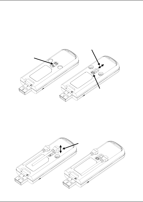
Connecting the antenna to the modem
Before connecting to the modem, move the slider covering the
antenna connector at the bottom of the USB modem to the “open”
position.
Connecting the antenna to the modem is shown in the picture
below.Connectors of the antenna cable must be carefully inserted
vertically into ports in the enclosure of the modem.
Slider
closed
Slider
open
Slider open/closed
direction
Connector
insert/extract