General Dynamics Broand USBSTKARM LTE Band 12 USB Stick Modem User Manual External Antenna Installation Instructions
General Dynamics Broadband, Inc. LTE Band 12 USB Stick Modem External Antenna Installation Instructions
Contents
- 1. User Guide
- 2. User Guide RF Exposure Addendum
- 3. External Antenna Installation Instructions
External Antenna Installation Instructions
RemoteAntennaforLTEModem
INSTRUCTIONSFORUSE

2
GeneralRemarks
Inordertoimprovethedatatransferperformance,theLTEmodemis
designedtowiththeremoteantenna.Theantennafeaturesamagnetic
basethatallowsyoutomountitonametalsurfacee.g.awindowsill.You
canalsoscrewtheantennaonthewalleitherinsideoroutside.
Theantennaisequippedwitha3mcableterminatedinsuitableRF
connectorsforconnectingtheremoteantennatothemodem.
Specifications
FrequencyRange690
–
750 MHz
Gainmax.1.7 dBi
PolarisationLinear,+/‐45o
PowerInputmax.4W
TemperatureRange ‐20oCto+55oC
CableLength3m
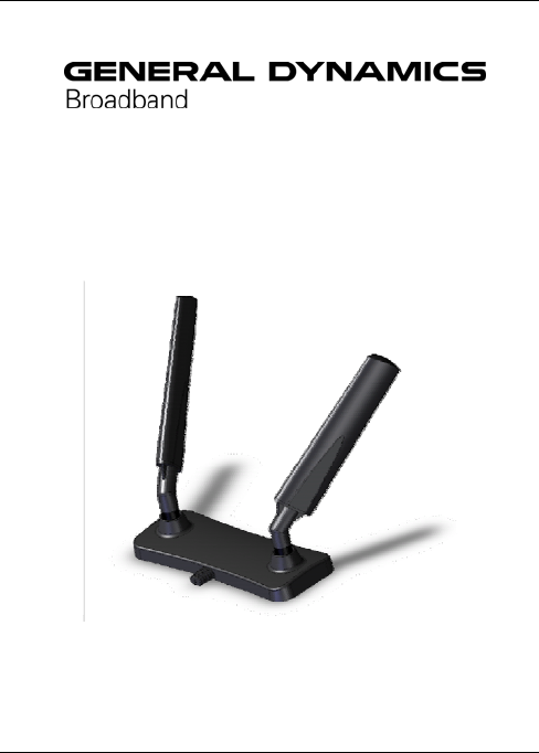
MountingtheAntenna
Beforeyouconnecttheantennatothemodemyoushouldassemblethe
antennaelementstothebaseunit.Gentlytightentheantennaelements
tothebaseunit.Afterattachingtheantennaelementsalignthemtoso
theyangledat45degreesrelativetotheantennabase.
3
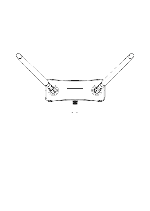
InstallationontheWall
• Installscrewsspacedtomatchthelocatinglugsintherearofthe
antenna,ensurethescrewheadsprotrudeapproximately1.5mm
abovethesurfaceofthewall.
• Locatedantennaontheonthescrewsasshownbelow.
4
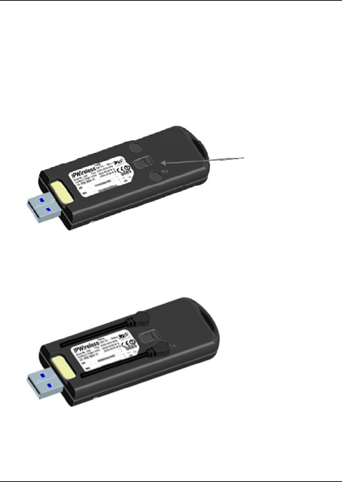
ConnectingtotheAntennaPortoftheModem
• Beforeconnectingtheremoteantenna,movetheslideronthe
bottomofthemodemtorevealtheantennaconnectors.Ensurethe
slidersisfullyopen.
• Connecttheremoteantennaconnectorstothemodemasshown
below.
• Bothcablesfromtheremoteantennamustbeconnectedtothe
modem.
AntennaSlider