General Dynamics C4 Systems MXU2000N-R Fixed Satellite Tranceiver User Manual MXUEXH7B
General Dynamics C4 Systems Fixed Satellite Tranceiver MXUEXH7B
Contents
- 1. Exhibit 7A Administration Manual
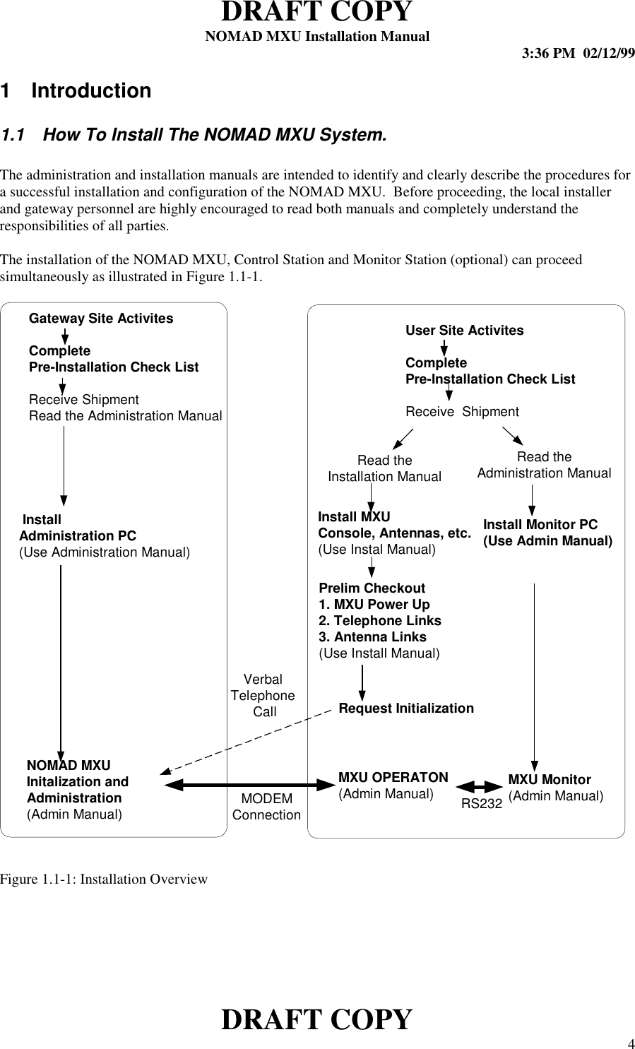
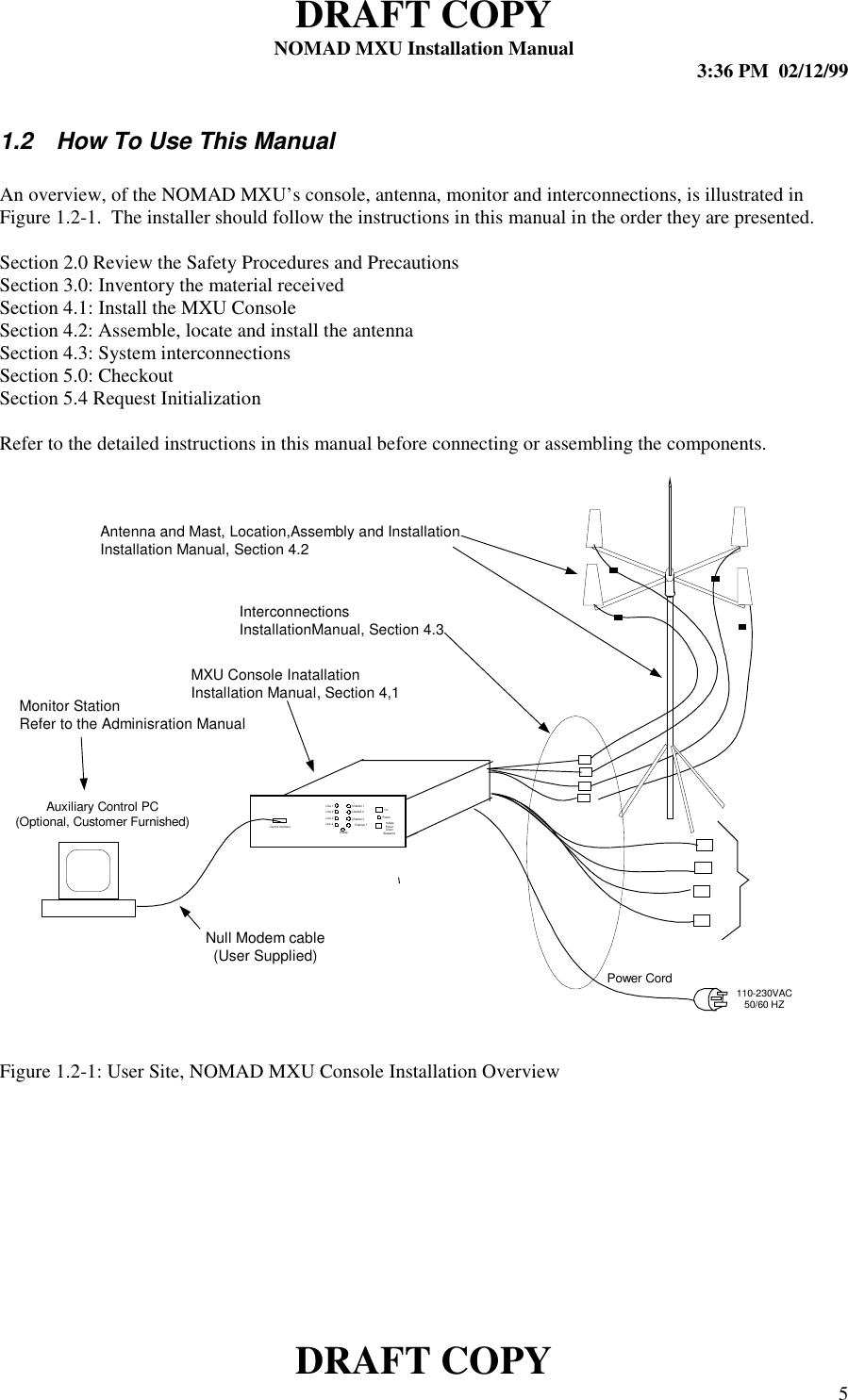
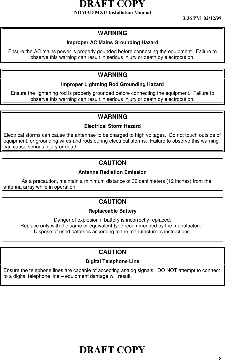
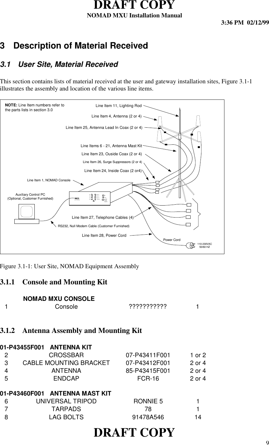
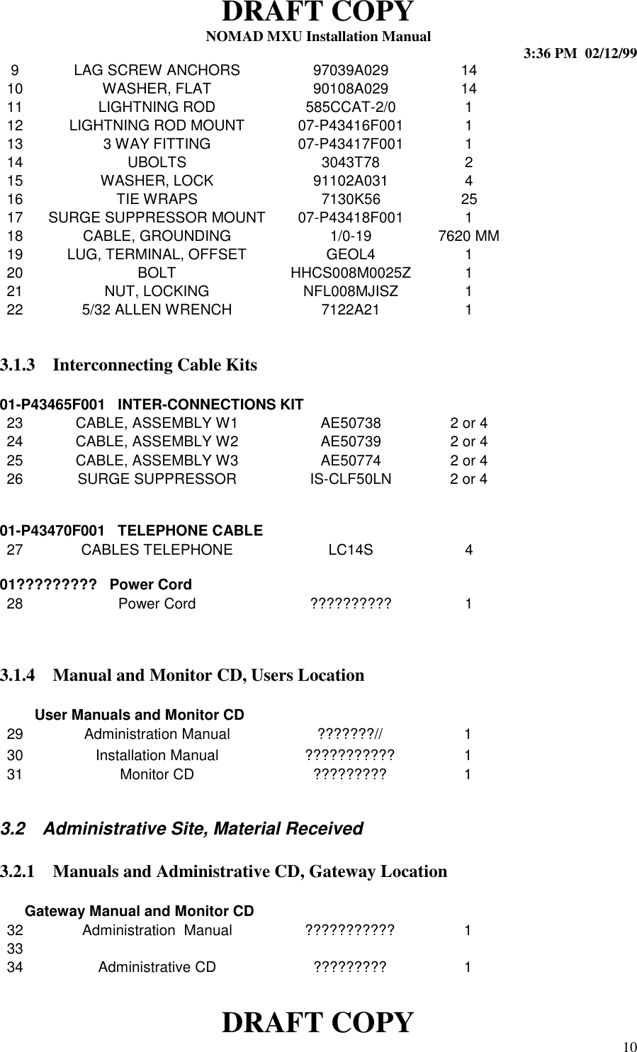
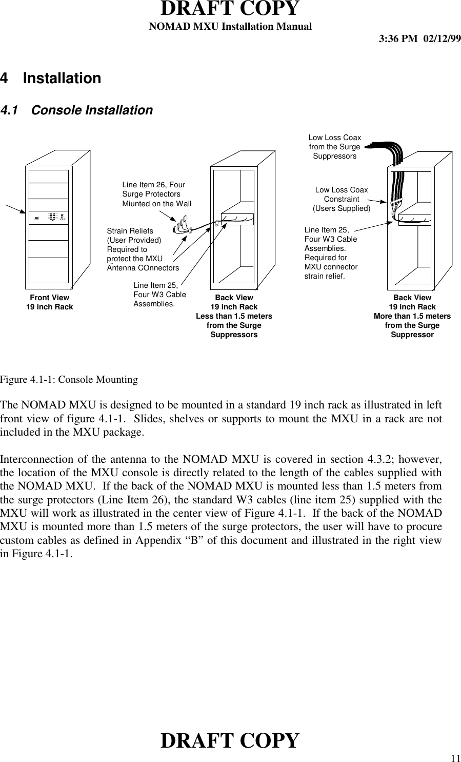
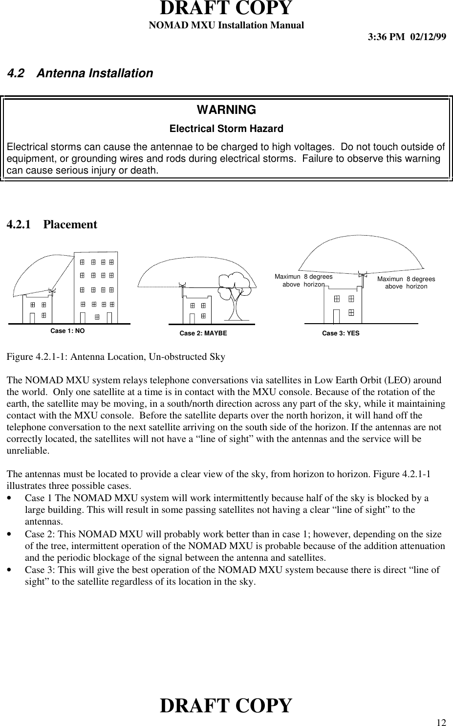
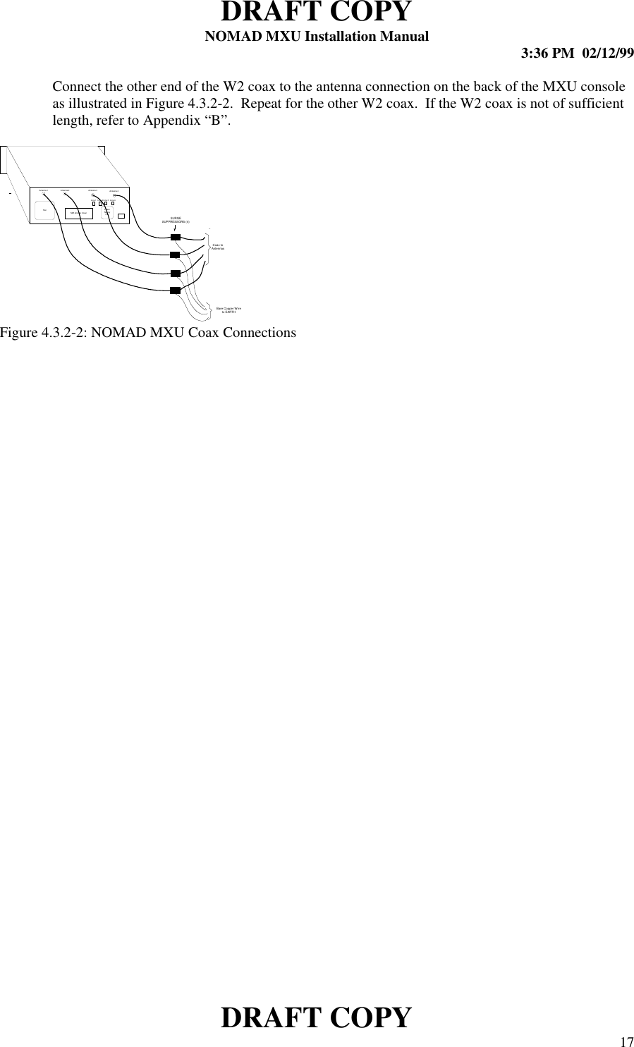
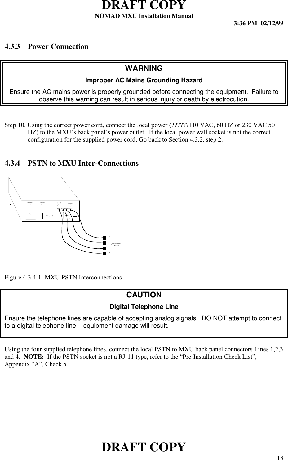
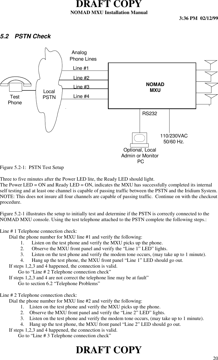
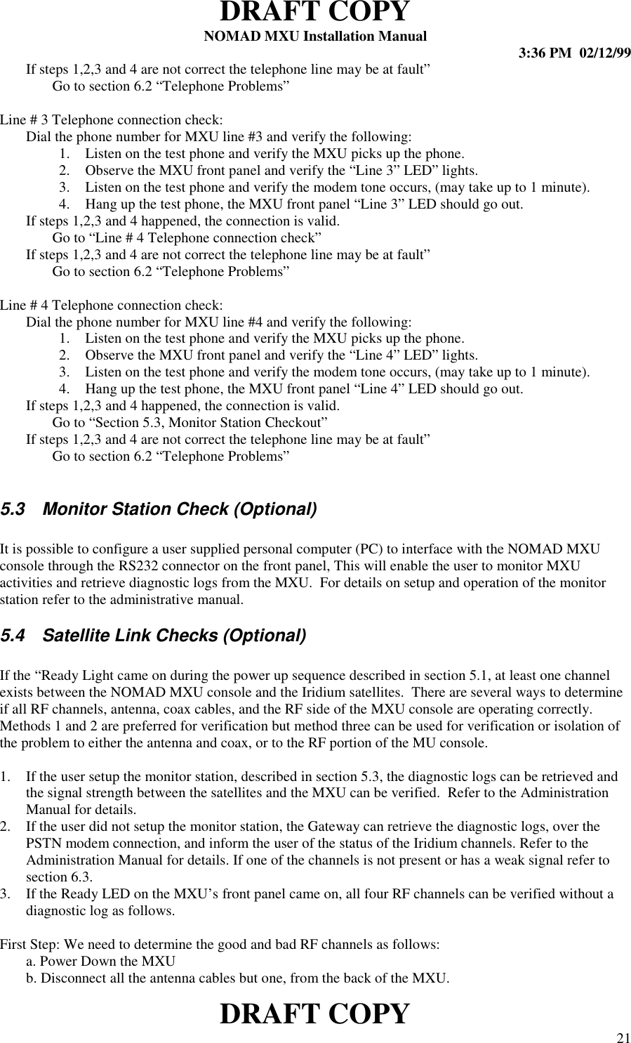
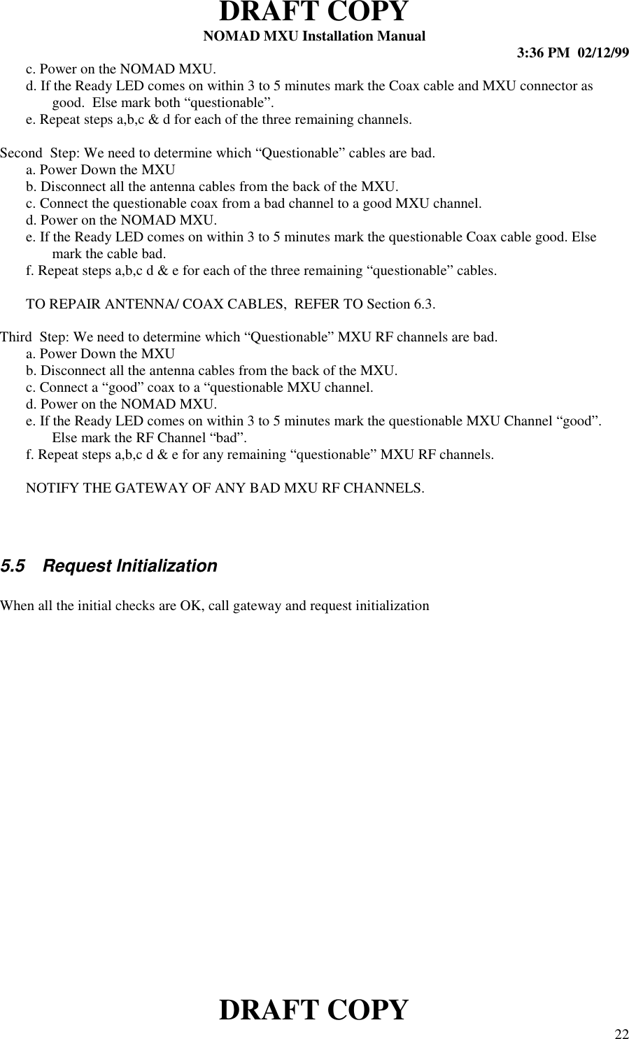
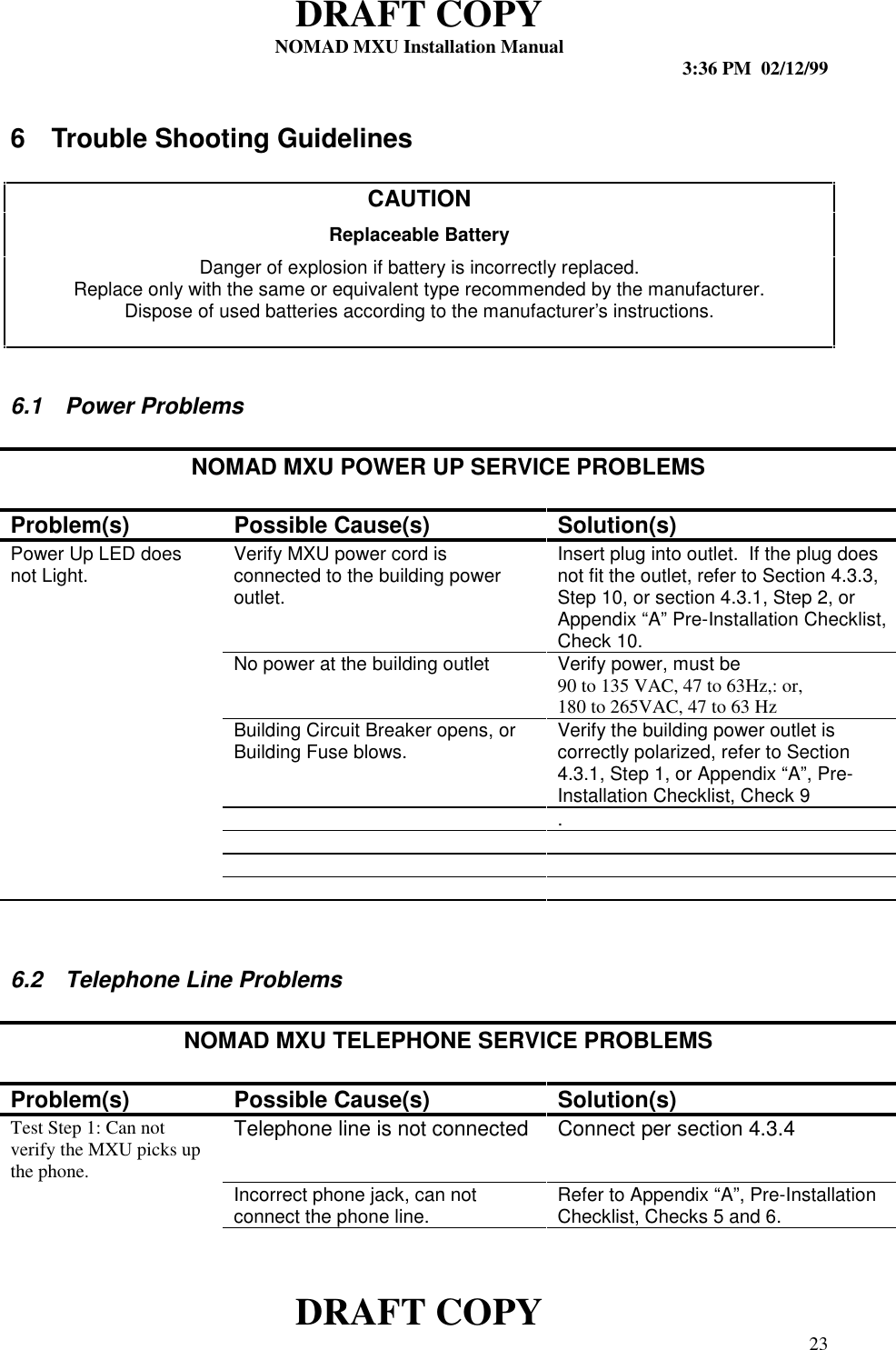
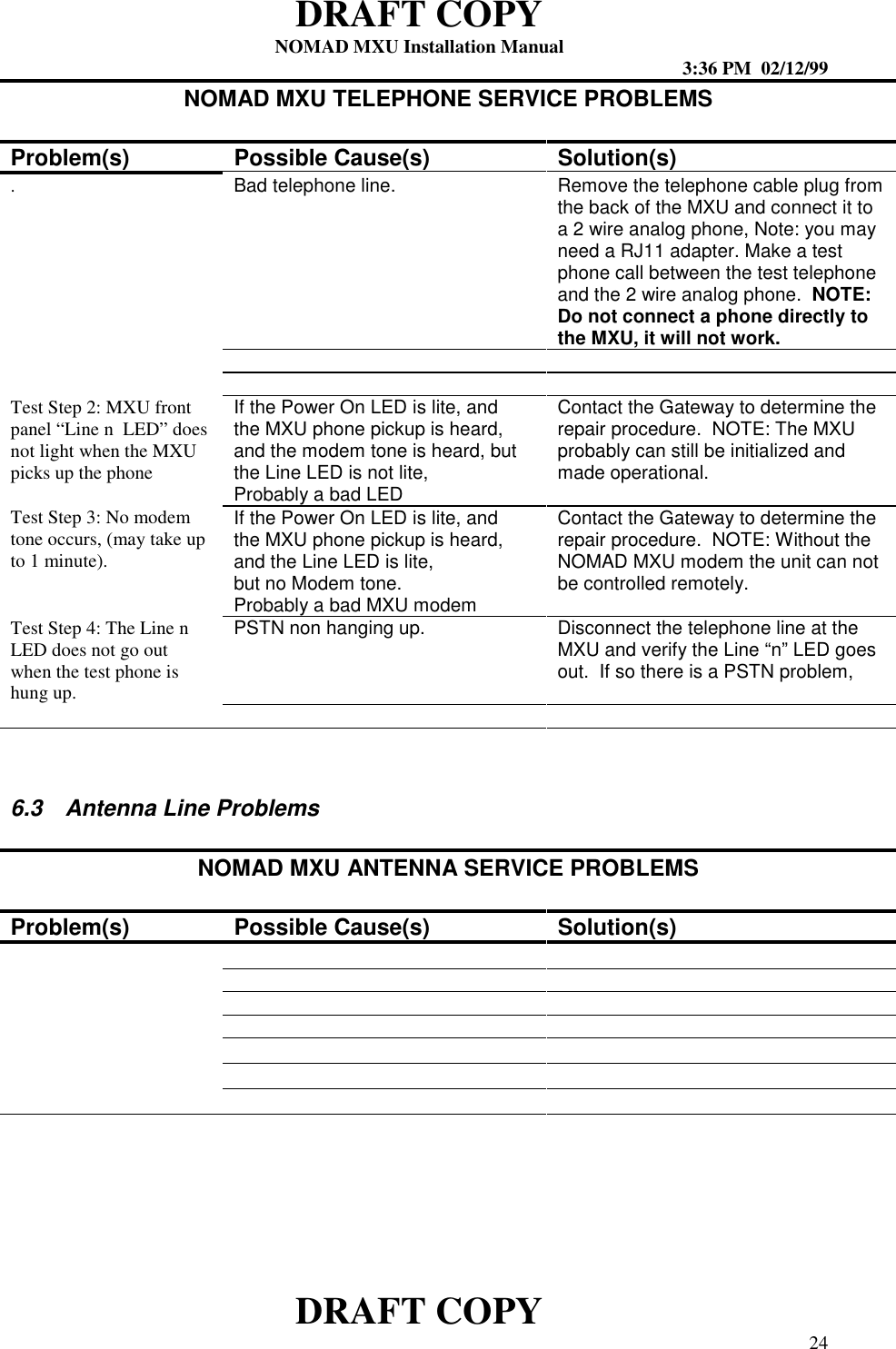
- 2. Exhibit 7B Installation Manual
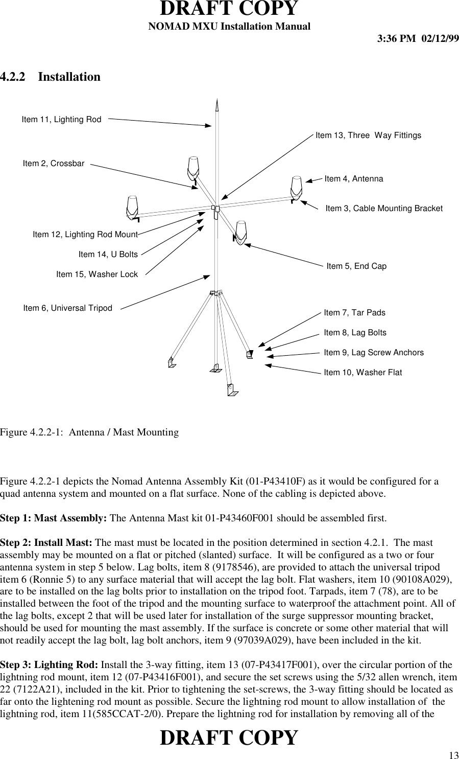
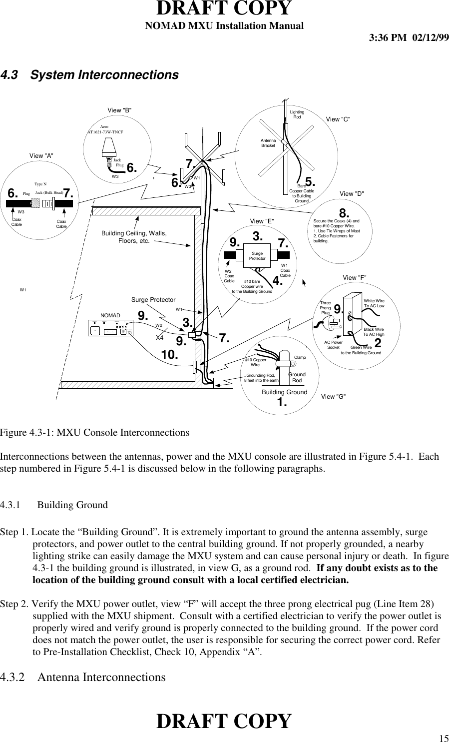
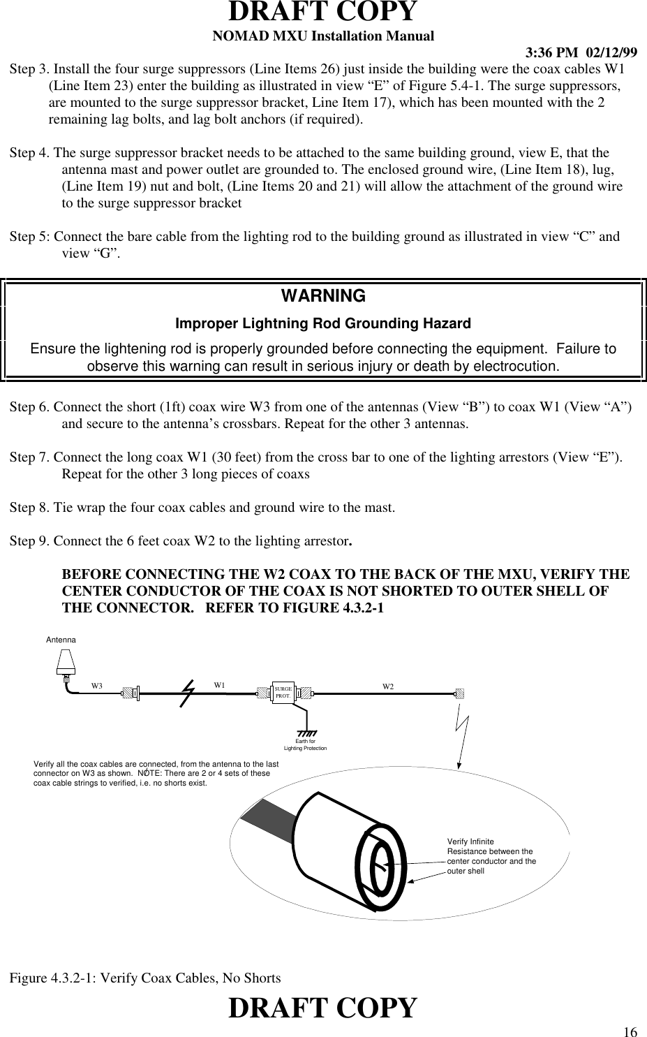
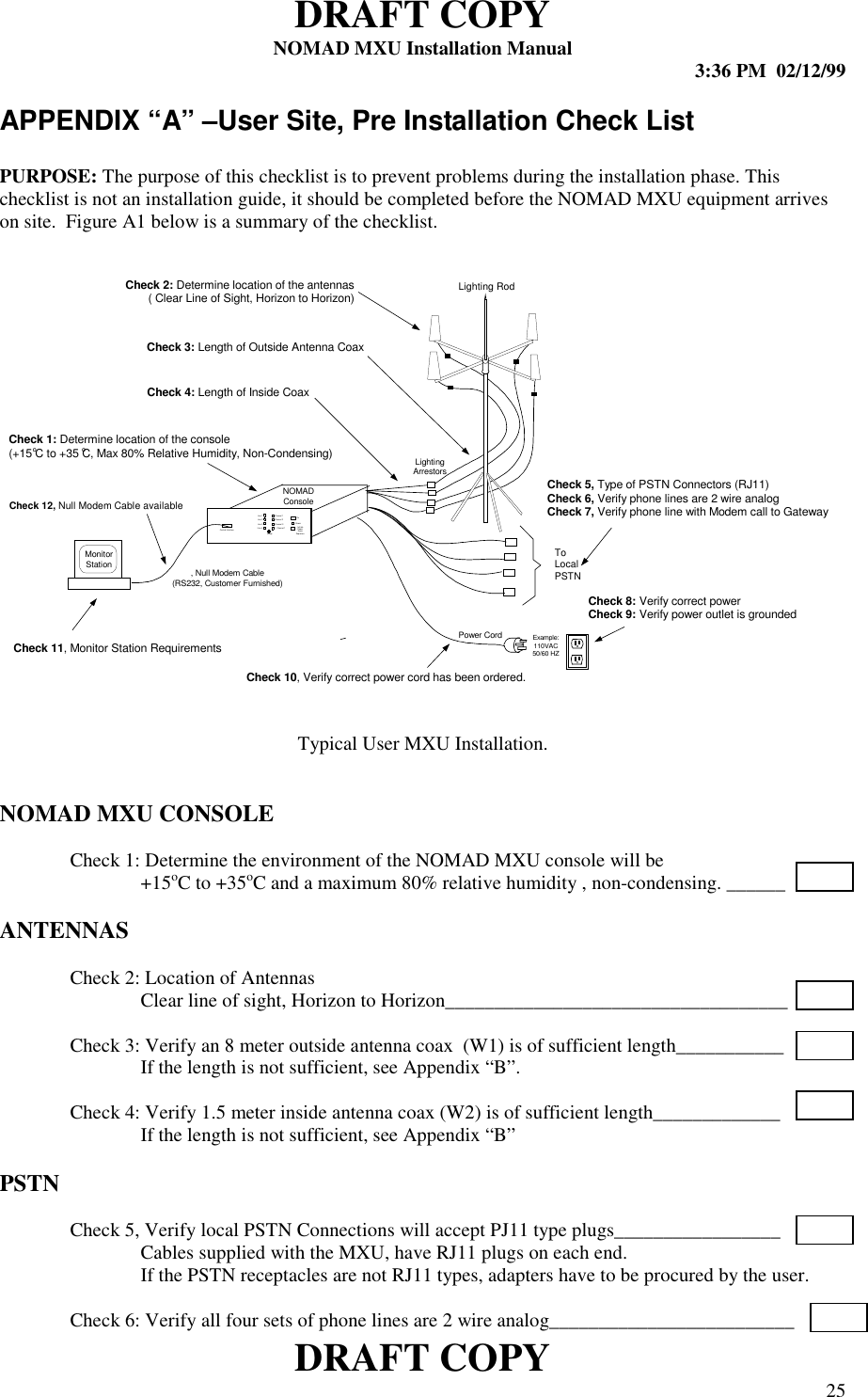
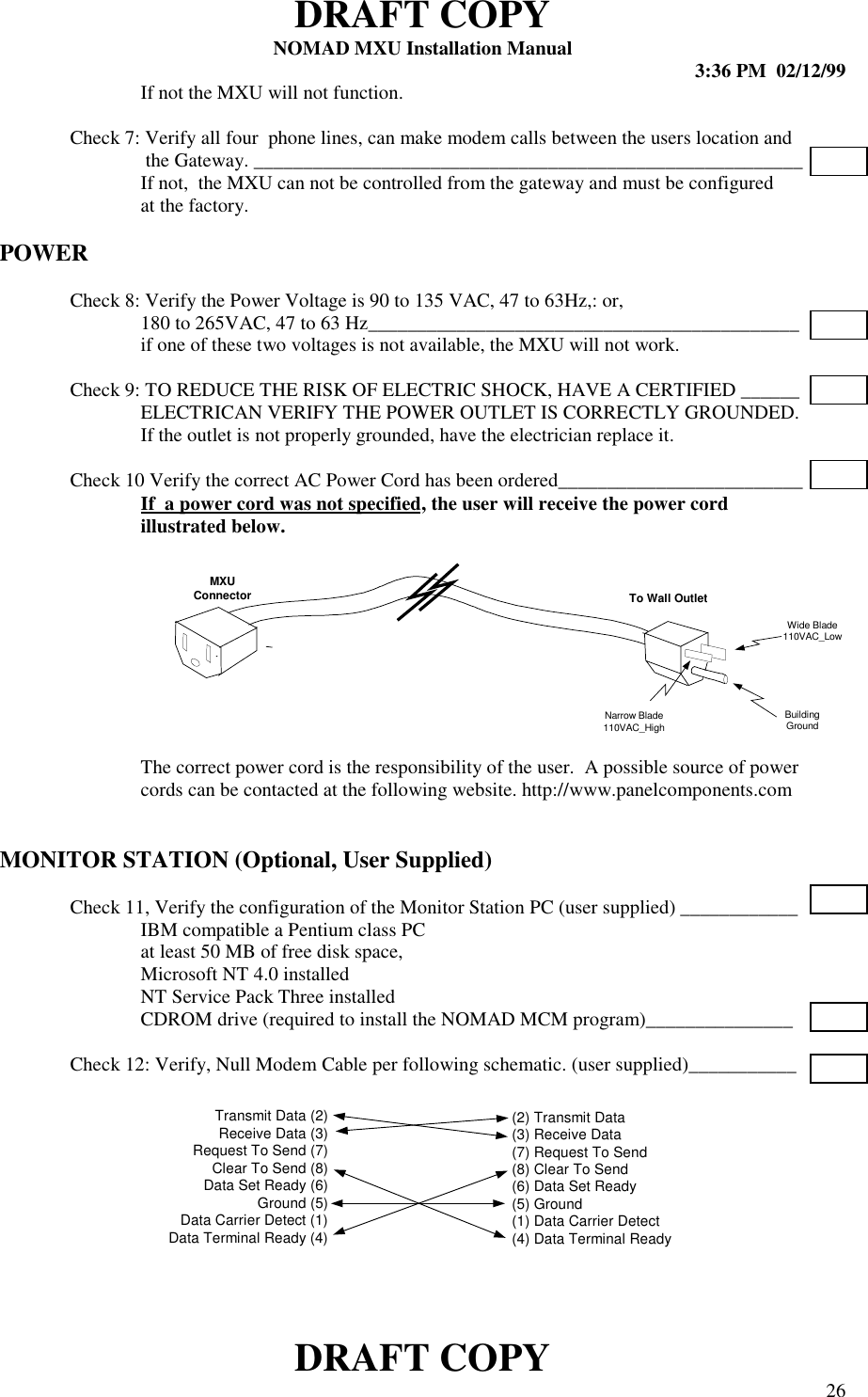
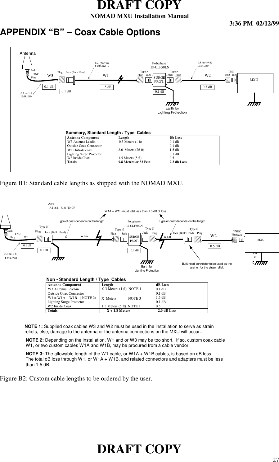
Exhibit 7B Installation Manual