General Dynamics C4 Systems MXU2000N-R Fixed Satellite Tranceiver User Manual MXUEXH7B
General Dynamics C4 Systems Fixed Satellite Tranceiver MXUEXH7B
Contents
- 1. Exhibit 7A Administration Manual
- 2. Exhibit 7B Installation Manual
Exhibit 7B Installation Manual

APPLICANT: MOTOROLA GSTG FCC ID: MIJMXU2000N-R
DRAFT OF INSTALLATION MANUAL
EXHIBIT 7B
DRAFT COPY
NOMAD MXU Installation Manual 3:36 PM 02/12/99
DRAFT COPY 1
ASTERISK INDICATES DATA
REVISIONS
WHICH IS NONMANDATORY REV DESCRIPTION DATE APPROVED
FOR INFORMATION ONLY XA Engineering Red Line Control 3 Feb 99 KHS
*APPLICATION XB
NEXT ASSY USED ON
SEE SEPARATE WIRE LIST YES NO XSEE SEPARATE PARTS LIST YES NO X
PROJ. NO. DWN BY INTERPRET DRAWING IN ACCORDANCE
14114 Ken Schmidt WITH STANDARDS LISTED IN DOD-STD-100.
UNLESS
OTHERWISE
SPECIFIED:
DOC CHK BY
SCOTTSDALE, A
Z
85252-1417
S
p
ace and S
y
stems Technolo
gy
Grou
p
DSGN CHK BY
ALL DIMENSIONS
ARE INCHES. CONTR NO.
DWG IS END
PROD. NOMAD MXU INSTALLATION MANUAL
ISSUED
TOLERANCES:
2 PLACE
DEC ± N/A MATL APVD
3 PLACE MFG APVD
DEC ± N/A SIZE CAGE CODE DRAWING NO.
ENGRG APVD A 94990
HOLE DIA
N/A CUST APVD
ANGLE ± N/A NA SCALE NONE WT. NA SHEET 1 OF

DRAFT COPY
NOMAD MXU Installation Manual 3:36 PM 02/12/99
DRAFT COPY 2
PRE-INSTALLATION CHECKLIST
Refer to Appendix “A” for the “NOMAD MXU Pre-Installation
Checklist”. The checklist should have been completed before the
NOMAD MXU was ordered, or at least before the MXU shipment
arrived on site. The intent of the checklist is to prevent problems during
the installation stages defined in this document.
SERVICE INFORMATION
Contact the Gateway for questions concerning the installation,
initialization and operation of the NOMAD MXU System
MANUAL REVISION HISTORY
Version Date Name Reason
Version Date name Change
XA 3/Feb/99 KHS Initial draft copy, engineering release, Note: Copy sent to FCC
XB
DRAFT COPY
NOMAD MXU Installation Manual 3:36 PM 02/12/99
DRAFT COPY 3
TABLE OF CONTENTS
1 Introduction...........................................................................................................................................4
1.1 How To Install The NOMAD MXU System. ................................................................................. 4
1.2 How To Use This Manual............................................................................................................... 5
1.3 Acronyms and Definitions ..............................................................................................................6
2 Safety......................................................................................................................................................7
2.1 Safety Procedures and Precautions ................................................Error! Bookmark not defined.
2.1.1 General Hazard Areas. ............................................................................................................ 7
3 Description of Material Received ........................................................................................................9
3.1 User Site, Material Received...........................................................................................................9
3.1.1 Console and Mounting Kit...................................................................................................... 9
3.1.2 Antenna Assembly and Mounting Kit.....................................................................................9
3.1.3 Interconnecting Cable Kits....................................................................................................10
3.1.4 Manual and Monitor CD, Users Location............................................................................. 10
3.2 Administrative Site, Material Received ........................................................................................10
3.2.1 Manuals and Administrative CD, Gateway Location............................................................10
4 Installation...........................................................................................................................................11
4.1 Console Installation.......................................................................................................................11
4.2 Antenna Installation ...................................................................................................................... 12
4.2.1 Placement.............................................................................................................................. 12
4.2.2 Installation.............................................................................................................................13
4.3 System Interconnections............................................................................................................... 15
4.3.1 Building Ground ................................................................................................................... 15
4.3.2 Antenna Interconnections...................................................................................................... 15
4.3.3 Power Connection.................................................................................................................18
4.3.4 PSTN to MXU Inter-Connections.........................................................................................18
5 Checkout..............................................................................................................................................19
5.1 Initial Power Up Checks ...............................................................................................................19
5.2 PSTN Check..................................................................................................................................20
5.3 Monitor Station Check (Optional) ................................................................................................21
5.4 Satellite Link Checks (Optional)...................................................................................................21
5.5 Request Initialization .................................................................................................................... 22
6 Trouble Shooting Guidelines..............................................................................................................23
6.1 Power Problems ............................................................................................................................23
6.2 Telephone Line Problems .............................................................................................................23
6.3 Antenna Line Problems................................................................................................................. 24
APPENDIX “A” –User Site, Pre Installation Check List........................................................................ 25
APPENDIX “B” – Coax Cable Options....................................................................................................27
TABLE OF FIGURES
Figure 4.1-1: Console Mounting................................................................................................................... 11
Figure 4.2.2-1: Antenna / Mast Mounting ................................................................................................... 13
Figure 4.3-1: MXU Console Interconnections.............................................................................................. 15
Figure 4.3.2-2: NOMAD MXU Coax Connections......................................................................................17
Figure 4.3.4-1: MXU PSTN Interconnections..............................................................................................18
Figure 5.2-1: PSTN Test Setup....................................................................................................................20
DRAFT COPY
NOMAD MXU Installation Manual 3:36 PM 02/12/99
DRAFT COPY 4
1 Introduction
1.1 How To Install The NOMAD MXU System.
The administration and installation manuals are intended to identify and clearly describe the procedures for
a successful installation and configuration of the NOMAD MXU. Before proceeding, the local installer
and gateway personnel are highly encouraged to read both manuals and completely understand the
responsibilities of all parties.
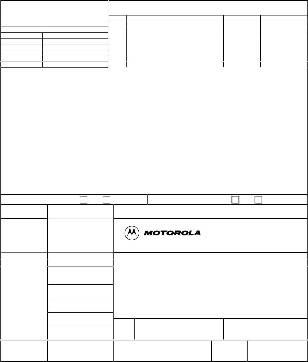
The installation of the NOMAD MXU, Control Station and Monitor Station (optional) can proceed
simultaneously as illustrated in Figure 1.1-1.
Figure 1.1-1: Installation Overview
Gateway Site Activites
Complete
Pre-Installation Check List
Receive Shipment
Read the Administration Manual
User Site Activites
Complete
Pre-Installation Check List
Receive Shipment
Install MXU
Console, Antennas, etc.
(Use Instal Manual)
Prelim Checkout
1. MXU Power Up
2. Telephone Links
3. Antenna Links
(Use Install Manual)
Install
Administration PC
(Use Administration Manual)
MXU OPERATON
(Admin Manual)
Install Monitor PC
(Use Admin Manual)
NOMAD MXU
Initalization and
Administration
(Admin Manual)
MXU Monitor
(Admin Manual)
Request Initialization
Verbal
Telephone
Call
MODEM
Connection RS232
Read the
Installation Manual
Read the
Administration Manual
DRAFT COPY
NOMAD MXU Installation Manual 3:36 PM 02/12/99
DRAFT COPY 5
1.2 How To Use This Manual
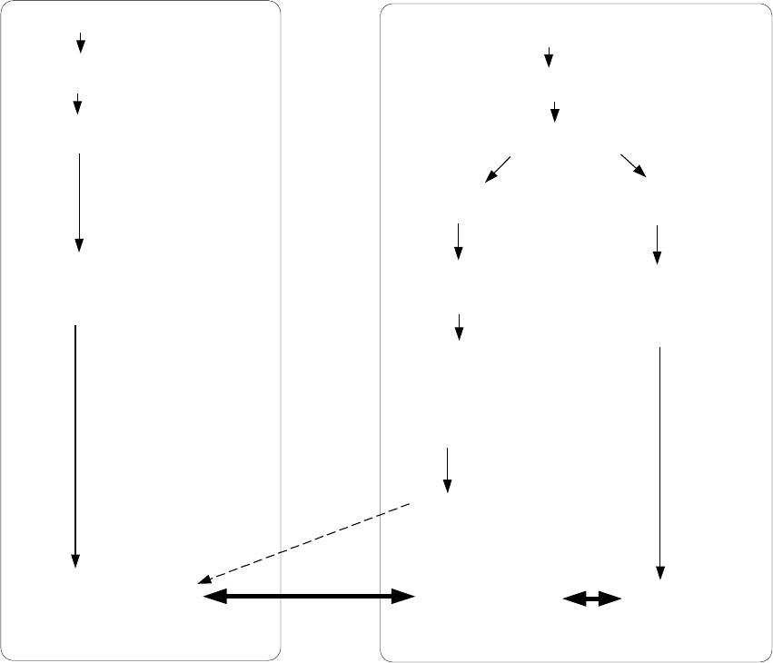
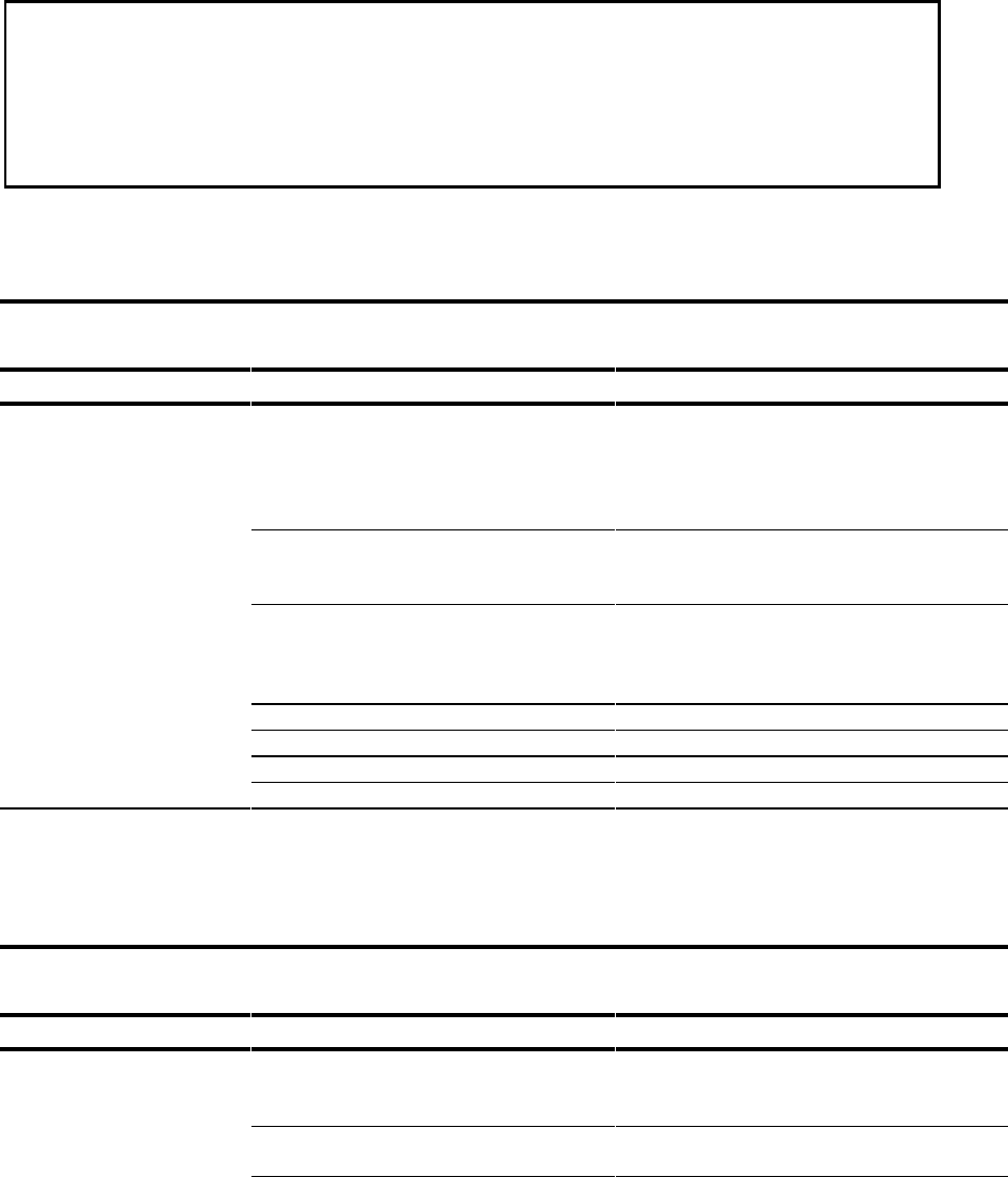
An overview, of the NOMAD MXU’s console, antenna, monitor and interconnections, is illustrated in
Figure 1.2-1. The installer should follow the instructions in this manual in the order they are presented.
Section 2.0 Review the Safety Procedures and Precautions
Section 3.0: Inventory the material received
Section 4.1: Install the MXU Console
Section 4.2: Assemble, locate and install the antenna
Section 4.3: System interconnections
Section 5.0: Checkout
Section 5.4 Request Initialization
Refer to the detailed instructions in this manual before connecting or assembling the components.
Figure 1.2-1: User Site, NOMAD MXU Console Installation Overview
Line 1
Line 2
Line 3
Line 4
Ch annel 1
Cha nnel 2
Ch annel 3
On
Ready
Power
Chan nel 1 Initiate
Power
Down
Sequenc e
Control Interface
110-230VAC
50/60 HZ
Auxiliary Control PC
(Optional, Customer Furnished)
Power Cord
MXU Console Inatallation
Installation Manual, Section 4,1
Antenna and Mast, Location,Assembly and Installation
Installation Manual, Section 4.2
Monitor Station
Refer to the Adminisration Manual
Null Modem cable
(User Supplied)
Interconnections
InstallationManual, Section 4.3
DRAFT COPY
NOMAD MXU Installation Manual 3:36 PM 02/12/99
DRAFT COPY 6
1.3 Acronyms and Definitions
CDR Call Detail Record
CD ROM Compact Disk Read Only Memory
CFB Call Forward on subscriber Busy
DTMF Dual tone Multi-Frequency
ISDN Integrated Service Digital Network
ISU Iridium Subscriber Unit, i.e. an Iridium phone
LBT L Band Transceiver
LEO Low Earth Orbit
MCM MXU Configuration Management
MSISDN Mobile Service Integrated Service Digital Network
MXU MultiExchange Unit
NOMAD An Iridium program utilizing commercial MXUs and ISUs with modified features
NOMAD MXU A Standard MXU modified with special features specific to the NOMAD program
NOMAD ISU A standard ISU modified with special features specific to the NOMAD program
PBX Public Branch Exchange
PC Personal Computer
PSTN Public Switched Telephone Network
SIM Subscriber Identity Module
DRAFT COPY
NOMAD MXU Installation Manual 3:36 PM 02/12/99
DRAFT COPY 7
2 Safety
2.1 General Hazard Areas.
Those safety issues that could pose a concern are discussed within this document
and listed below:
• AC power is not removed internal to the NOMAD MXU console by pushing the front panel
switch.
• Do not open the unit. There are no serviceable components within the system. Contact the Iridium
gateway for service instructions.
• RF energy emitted by the antennae is of a very low level but as a precaution, it is recommended to
maintain a physical distance of 30 cm while the unit is operating.
2.2 Specific Hazard Areas
The specific areas of concern are detailed as follows:
The precautions stated below must be observed to prevent personal injury, death or equipment damage:
• When possible, the power supply in the unit should be shut off before beginning work on the
equipment. Note: Power can only be removed from the unit by disconnecting the AC power cable
from the building mains power .
• The telephone lines have hazardous DC voltages and currents associated with the ringing system.
•The main power (i.e. 50/60 Hertz, 115/240 VAC) supplies hazardous AC voltage and current to the
unit via the power cable.
•The antenna array is exposed to lighting hazards. Installation of lightning arrestors and proper
connection to the building ground is necessary to avoid personal injury or death. Note: The
attached ground wire may burn or vaporize during electrical storms.
•Outside communications wiring connected to the equipment should be handled with caution because of
possible lightning voltages or ring voltages/currents that could be present and hazardous while in a
disconnected condition.
•AC mains power can ONLY be removed from this equipment by disconnecting the AC power cable
from the building mains power. Always disconnect the cable by handling the connector, not the
cable itself.
•The AC power cable supplied has been selected to comply with the units power requirements and all
applicable safety standards. Do not use another cable or otherwise modify it without contacting
the Iridium Gateway for instructions.
2.3 Labels
The following labels either warn or caution service and operator personnel of safety hazards that could be
associated with the MXU. They are located within this document as well as on the unit itself.

DRAFT COPY
NOMAD MXU Installation Manual 3:36 PM 02/12/99
DRAFT COPY 8
WARNING
Improper AC Mains Grounding Hazard
Ensure the AC mains power is properly gounded before connecting the equipment. Failure to
observe this warning can result in serious injury or death by electrocution.
WARNING
Improper Lightning Rod Grounding Hazard
Ensure the lightening rod is properly grounded before connecting the equipment. Failure to
observe this warning can result in serious injury or death by electrocution.
WARNING
Electrical Storm Hazard
Electrical storms can cause the antennae to be charged to high voltages. Do not touch outside of
equipment, or grounding wires and rods during electrical storms. Failure to observe this warning
can cause serious injury or death.
CAUTION
Antenna Radiation Emission
As a precaution, maintain a minimum distance of 30 centimeters (12 inches) from the
antenna array while in operation.
CAUTION
Replaceable Battery
Danger of explosion if battery is incorrectly replaced.
Replace only with the same or equivalent type recommended by the manufacturer.
Dispose of used batteries according to the manufacturer’s instructions.
CAUTION
Digital Telephone Line
Ensure the telephone lines are capable of accepting analog signals. DO NOT attempt to connect
to a digital telephone line – equipment damage will result.
DRAFT COPY
NOMAD MXU Installation Manual 3:36 PM 02/12/99
DRAFT COPY 9
3 Description of Material Received
3.1 User Site, Material Received
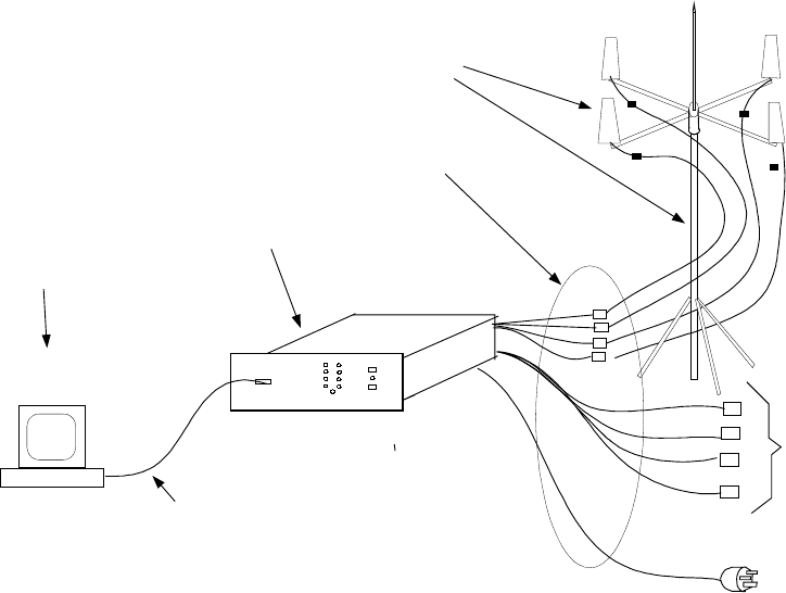
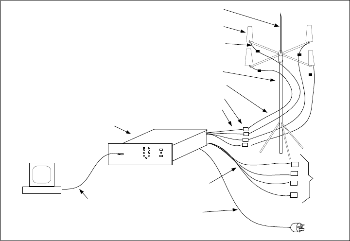
This section contains lists of material received at the user and gateway installation sites, Figure 3.1-1
illustrates the assembly and location of the various line items.
Figure 3.1-1: User Site, NOMAD Equipment Assembly
3.1.1 Console and Mounting Kit
NOMAD MXU CONSOLE
1 Console ??????????? 1
3.1.2 Antenna Assembly and Mounting Kit
01-P43455F001 ANTENNA KIT
2 CROSSBAR 07-P43411F001 1 or 2
3 CABLE MOUNTING BRACKET 07-P43412F001 2 or 4
4 ANTENNA 85-P43415F001 2 or 4
5 ENDCAP FCR-16 2 or 4
01-P43460F001 ANTENNA MAST KIT
6 UNIVERSAL TRIPOD RONNIE 5 1
7 TARPADS 78 1
8 LAG BOLTS 91478A546 14
Line 1
Line 2
Line 3
Line 4
Channel 1
Channel 2
Channel 3
On
Ready
Power
Chann el 1 Init iate
Power
Down
Sequence
Cont rol Inte rface
110-230VAC
50/60 HZ
Line Item 4, Antenna (2 or 4)
Auxiliary Control PC
(Optional, Customer Furnished)
RS232, Null Modem Cable (Customer Furnished)
Power Cord
Line Item 26, Surge Suppressors (2 or 4)
Line Item 1, NOMAD Console
Line Item 11, Lighting Rod
Line Item 23, Ouside Coax (2 or 4)
Line Item 24, Inside Coax (2 or4)
Line Item 25, Antenna Lead In Coax (2 or 4)
Line Item 27, Telephone Cables (4)
Line Item 28, Power Cord
Line Items 6 - 21, Antenna Mast Kit
NOTE:
Line Item numbers refer to
the parts lists in section 3.0
DRAFT COPY
NOMAD MXU Installation Manual 3:36 PM 02/12/99
DRAFT COPY 10
9 LAG SCREW ANCHORS 97039A029 14
10 WASHER, FLAT 90108A029 14
11 LIGHTNING ROD 585CCAT-2/0 1
12 LIGHTNING ROD MOUNT 07-P43416F001 1
13 3 WAY FITTING 07-P43417F001 1
14 UBOLTS 3043T78 2
15 WASHER, LOCK 91102A031 4
16 TIE WRAPS 7130K56 25
17 SURGE SUPPRESSOR MOUNT 07-P43418F001 1
18 CABLE, GROUNDING 1/0-19 7620 MM
19 LUG, TERMINAL, OFFSET GEOL4 1
20 BOLT HHCS008M0025Z 1
21 NUT, LOCKING NFL008MJISZ 1
22 5/32 ALLEN WRENCH 7122A21 1
3.1.3 Interconnecting Cable Kits
01-P43465F001 INTER-CONNECTIONS KIT
23 CABLE, ASSEMBLY W1 AE50738 2 or 4
24 CABLE, ASSEMBLY W2 AE50739 2 or 4
25 CABLE, ASSEMBLY W3 AE50774 2 or 4
26 SURGE SUPPRESSOR IS-CLF50LN 2 or 4
01-P43470F001 TELEPHONE CABLE
27 CABLES TELEPHONE LC14S 4
01????????? Power Cord
28 Power Cord ?????????? 1
3.1.4 Manual and Monitor CD, Users Location
User Manuals and Monitor CD
29 Administration Manual ???????// 1
30 Installation Manual ??????????? 1
31 Monitor CD ????????? 1
3.2 Administrative Site, Material Received
3.2.1 Manuals and Administrative CD, Gateway Location
Gateway Manual and Monitor CD
32 Administration Manual ??????????? 1
33
34 Administrative CD ????????? 1
DRAFT COPY
NOMAD MXU Installation Manual 3:36 PM 02/12/99
DRAFT COPY 11
4 Installation
4.1 Console Installation
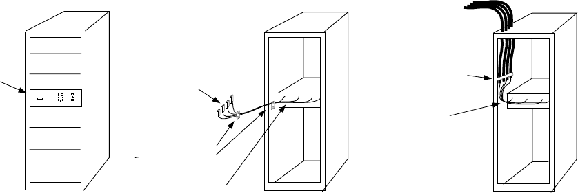
Figure 4.1-1: Console Mounting
The NOMAD MXU is designed to be mounted in a standard 19 inch rack as illustrated in left
front view of figure 4.1-1. Slides, shelves or supports to mount the MXU in a rack are not
included in the MXU package.
Interconnection of the antenna to the NOMAD MXU is covered in section 4.3.2; however,
the location of the MXU console is directly related to the length of the cables supplied with
the NOMAD MXU. If the back of the NOMAD MXU is mounted less than 1.5 meters from
the surge protectors (Line Item 26), the standard W3 cables (line item 25) supplied with the
MXU will work as illustrated in the center view of Figure 4.1-1. If the back of the NOMAD
MXU is mounted more than 1.5 meters of the surge protectors, the user will have to procure
custom cables as defined in Appendix “B” of this document and illustrated in the right view
in Figure 4.1-1.
Line 1
Line 2
Line 3
Line 4
Channel 1
Channel 2
Channel 3
On
Ready
Power
Channel 1 Initiate
Power
Down
Sequence
Contr ol In ter fac e
Front View
19 inch Rack Back View
19 inch Rack
Less than 1.5 meters
from the Surge
Suppressors
Back View
19 inch Rack
More than 1.5 meters
from the Surge
Suppressor
Low Loss Coax
from the Surge
Suppressors
Low Loss Coax
Constraint
(Users Supplied)
Line Item 25,
Four W3 Cable
Assemblies.
Required for
MXU connector
strain relief.
Line Item 25,
Four W3 Cable
Assemblies.
Line Item 26, Four
Surge Protectors
Miunted on the Wall
Strain Reliefs
(User Provided)
Required to
protect the MXU
Antenna COnnectors
DRAFT COPY
NOMAD MXU Installation Manual 3:36 PM 02/12/99
DRAFT COPY 12
4.2 Antenna Installation
WARNING
Electrical Storm Hazard
Electrical storms can cause the antennae to be charged to high voltages. Do not touch outside of
equipment, or grounding wires and rods during electrical storms. Failure to observe this warning
can cause serious injury or death.
4.2.1 Placement
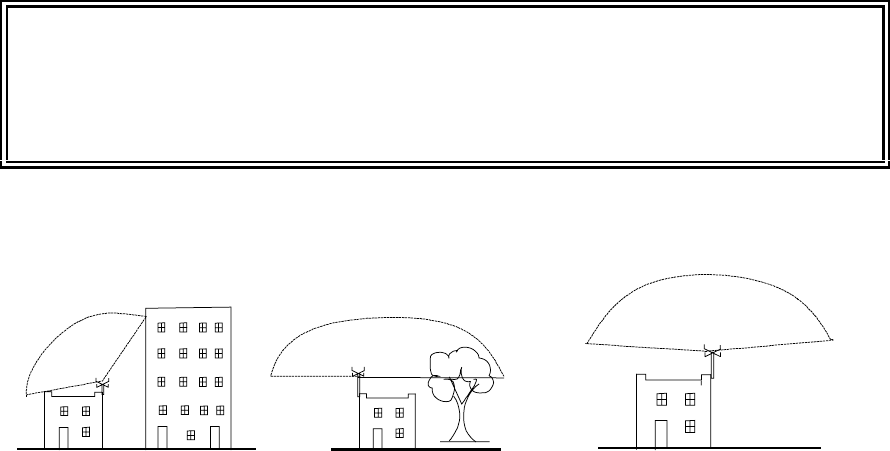
Figure 4.2.1-1: Antenna Location, Un-obstructed Sky
The NOMAD MXU system relays telephone conversations via satellites in Low Earth Orbit (LEO) around
the world. Only one satellite at a time is in contact with the MXU console. Because of the rotation of the
earth, the satellite may be moving, in a south/north direction across any part of the sky, while it maintaining
contact with the MXU console. Before the satellite departs over the north horizon, it will hand off the
telephone conversation to the next satellite arriving on the south side of the horizon. If the antennas are not
correctly located, the satellites will not have a “line of sight” with the antennas and the service will be
unreliable.
The antennas must be located to provide a clear view of the sky, from horizon to horizon. Figure 4.2.1-1
illustrates three possible cases.
• Case 1 The NOMAD MXU system will work intermittently because half of the sky is blocked by a
large building. This will result in some passing satellites not having a clear “line of sight” to the
antennas.
• Case 2: This NOMAD MXU will probably work better than in case 1; however, depending on the size
of the tree, intermittent operation of the NOMAD MXU is probable because of the addition attenuation
and the periodic blockage of the signal between the antenna and satellites.
• Case 3: This will give the best operation of the NOMAD MXU system because there is direct “line of
sight” to the satellite regardless of its location in the sky.
Case 1: NO Case 2: MAYBE Case 3: YES
Maximun 8 degrees
above horizon Maximun 8 degrees
above horizon
DRAFT COPY
NOMAD MXU Installation Manual 3:36 PM 02/12/99
DRAFT COPY 13
4.2.2 Installation
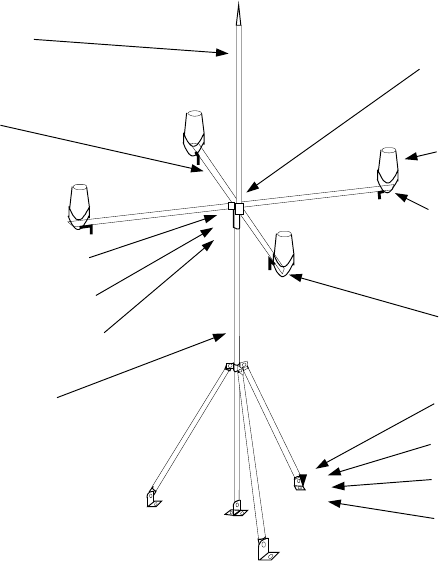
Figure 4.2.2-1: Antenna / Mast Mounting
Figure 4.2.2-1 depicts the Nomad Antenna Assembly Kit (01-P43410F) as it would be configured for a
quad antenna system and mounted on a flat surface. None of the cabling is depicted above.
Step 1: Mast Assembly: The Antenna Mast kit 01-P43460F001 should be assembled first.
Step 2: Install Mast: The mast must be located in the position determined in section 4.2.1. The mast
assembly may be mounted on a flat or pitched (slanted) surface. It will be configured as a two or four
antenna system in step 5 below. Lag bolts, item 8 (9178546), are provided to attach the universal tripod
item 6 (Ronnie 5) to any surface material that will accept the lag bolt. Flat washers, item 10 (90108A029),
are to be installed on the lag bolts prior to installation on the tripod foot. Tarpads, item 7 (78), are to be
installed between the foot of the tripod and the mounting surface to waterproof the attachment point. All of
the lag bolts, except 2 that will be used later for installation of the surge suppressor mounting bracket,
should be used for mounting the mast assembly. If the surface is concrete or some other material that will
not readily accept the lag bolt, lag bolt anchors, item 9 (97039A029), have been included in the kit.
Step 3: Lighting Rod: Install the 3-way fitting, item 13 (07-P43417F001), over the circular portion of the
lightning rod mount, item 12 (07-P43416F001), and secure the set screws using the 5/32 allen wrench, item
22 (7122A21), included in the kit. Prior to tightening the set-screws, the 3-way fitting should be located as
far onto the lightening rod mount as possible. Secure the lightning rod mount to allow installation of the
lightning rod, item 11(585CCAT-2/0). Prepare the lightning rod for installation by removing all of the
Item 11, Lighting Rod
Item 2, Crossbar
Item 12, Lighting Rod Mount
Item 14, U Bolts
Item 15, Washer Lock
Item 6, Universal Tripod
Item 13, Three Way Fittings
Item 4, Antenna
Item 5, End Cap
Item 3, Cable Mounting Bracket
Item 7, Tar Pads
Item 8, Lag Bolts
Item 9, Lag Screw Anchors
Item 10, Washer Flat
DRAFT COPY
NOMAD MXU Installation Manual 3:36 PM 02/12/99
DRAFT COPY 14
fasteners from the threaded end. Re-install one each of the nut, lock washer, and flat washer. Thread the
lightning rod into the mount and secure the jam nut.
The lightning rod mount shall be secured to the top of the mast by engaging the circular cut out portion of
the mount to the top of the mast and installing the u-bolts, item14 (3043T78), and lock washers, item 15
(91102A031).
Step 4: Grounding Cable: The lightning rod that extends from the top of the array has a grounding cable
(not shown above) attached and should be attached to the building ground in accordance with the
instructions in Section 4.3, step 5, below.
Step 5: Antennas: The Antenna kit 01-P43455F001 is now required to continue the assembly. The cross
bar(s), item 2 (07-P43411F001), slip through the 3-way fitting and should extend from the fitting an equal
distance on each side. Tighten the set-screws with the enclosed allen wrench to secure the cross bars.
The metal plate that the antenna, item 4 (07-P43412F001), is supplied with, is to be replaced by the cable-
mounting bracket, item 3 (07-P43415F001), included in the kit. If necessary, reorient the u-bolts to allow
the antenna, when installed on to the cross bar, to have the cone shape perpendicular to the cross bar. Install
the antenna onto the cross bar so that the antenna and it’s clamps are resting on the tape on the end of the
cross bar, and the cone is inverted above the cross bar as shown. The plastic end caps, item 5 (FCR-16),
that have been supplied shall be installed on the end of the cross bars.
Installation of the surge suppressors and coax cables are described in the following section.
DRAFT COPY
NOMAD MXU Installation Manual 3:36 PM 02/12/99
DRAFT COPY 15
4.3 System Interconnections
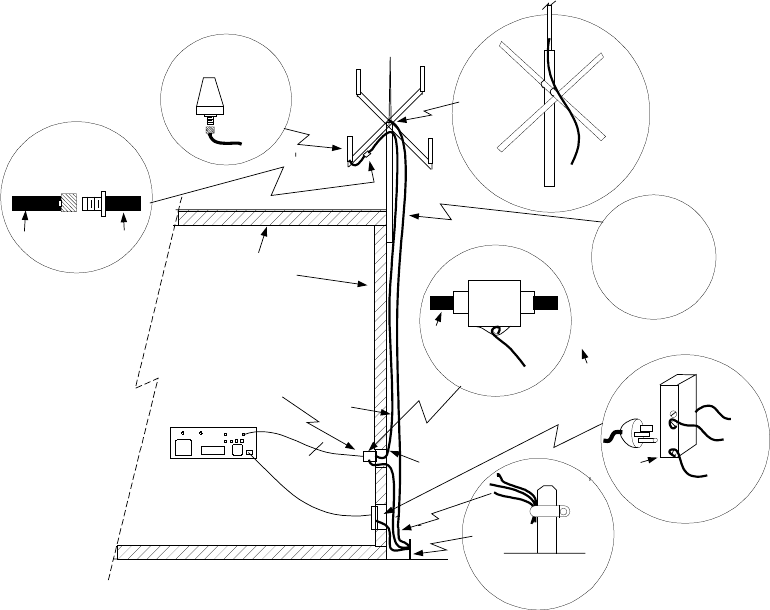
Figure 4.3-1: MXU Console Interconnections
Interconnections between the antennas, power and the MXU console are illustrated in Figure 5.4-1. Each
step numbered in Figure 5.4-1 is discussed below in the following paragraphs.
4.3.1 Building Ground
Step 1. Locate the “Building Ground”. It is extremely important to ground the antenna assembly, surge
protectors, and power outlet to the central building ground. If not properly grounded, a nearby
lighting strike can easily damage the MXU system and can cause personal injury or death. In figure
4.3-1 the building ground is illustrated, in view G, as a ground rod. If any doubt exists as to the
location of the building ground consult with a local certified electrician.
Step 2. Verify the MXU power outlet, view “F” will accept the three prong electrical pug (Line Item 28)
supplied with the MXU shipment. Consult with a certified electrician to verify the power outlet is
properly wired and verify ground is properly connected to the building ground. If the power cord
does not match the power outlet, the user is responsible for securing the correct power cord. Refer
to Pre-Installation Checklist, Check 10, Appendix “A”.
4.3.2 Antenna Interconnections
Fan Power
Supply
Fan
SIM Access Cover
Antenna 1 Antenna 2 Antenna 3 A ntenna 4
110-230VAC
50/60 HZ
Line 1 Line 2Line 3 Line 4
Lighting
Rod
Ground
Rod
AC Power
Socket
NOMAD
Grounding Rod,
8 feet into the earth
#10 Copper
Wire
Clamp
Green Wire
to the Building Ground
White Wire
To AC Low
Black Wire
To AC High
Three
Prong
Plug
#10 bare
Copper wire
to the Building Ground
Coax
Cable
Coax
Cable
Coax
Cable Coax
Cable
Bare
Copper Cable
to Building
Ground
Antenna
Bracket
Building Ceiling, Walls,
Floors, etc.
Building Ground
Secure the Coaxs (4) and
bare #10 Copper W ire.
1. Use Tie Wraps of Mast
2. Cable Fasteners for
building.
3.
2
5.
6.
1.
Surge
Protector
7.
View "A"
View "B"
View "C"
View "D"
View "E"
View "F"
8.
9. 9.
10.
4.
6.
7.
7.
X4
7.
3.
9.
9.
Plug
Type N
Jack (Bulk Head)
Aero
AT1621-73W-TNCF
Plug
Jack
View "G"
6.
Surge Protector
W3
W1
W2
W3
W3
W1
W1
W2
W1
DRAFT COPY
NOMAD MXU Installation Manual 3:36 PM 02/12/99
DRAFT COPY 16
Step 3. Install the four surge suppressors (Line Items 26) just inside the building were the coax cables W1
(Line Item 23) enter the building as illustrated in view “E” of Figure 5.4-1. The surge suppressors,
are mounted to the surge suppressor bracket, Line Item 17), which has been mounted with the 2
remaining lag bolts, and lag bolt anchors (if required).
Step 4. The surge suppressor bracket needs to be attached to the same building ground, view E, that the
antenna mast and power outlet are grounded to. The enclosed ground wire, (Line Item 18), lug,
(Line Item 19) nut and bolt, (Line Items 20 and 21) will allow the attachment of the ground wire
to the surge suppressor bracket
Step 5: Connect the bare cable from the lighting rod to the building ground as illustrated in view “C” and
view “G”.
WARNING
Improper Lightning Rod Grounding Hazard
Ensure the lightening rod is properly grounded before connecting the equipment. Failure to
observe this warning can result in serious injury or death by electrocution.
Step 6. Connect the short (1ft) coax wire W3 from one of the antennas (View “B”) to coax W1 (View “A”)
and secure to the antenna’s crossbars. Repeat for the other 3 antennas.
Step 7. Connect the long coax W1 (30 feet) from the cross bar to one of the lighting arrestors (View “E”).
Repeat for the other 3 long pieces of coaxs
Step 8. Tie wrap the four coax cables and ground wire to the mast.
Step 9. Connect the 6 feet coax W2 to the lighting arrestor.
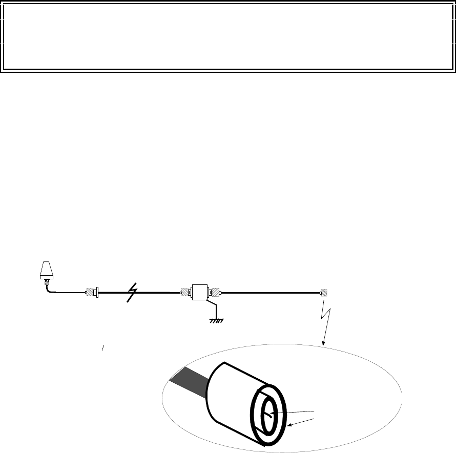
BEFORE CONNECTING THE W2 COAX TO THE BACK OF THE MXU, VERIFY THE
CENTER CONDUCTOR OF THE COAX IS NOT SHORTED TO OUTER SHELL OF
THE CONNECTOR. REFER TO FIGURE 4.3.2-1
Figure 4.3.2-1: Verify Coax Cables, No Shorts
SURGE
PROT.
W3
Earth for
Lighting Protection
W2
Verify Infinite
Resistance between the
center conductor and the
outer shell
Verify all the coax cables are connected, from the antenna to the last
connector on W3 as shown. NOTE: There are 2 or 4 sets of these
coax cable strings to verified, i.e. no shorts exist.
W1
Antenna
DRAFT COPY
NOMAD MXU Installation Manual 3:36 PM 02/12/99
DRAFT COPY 17
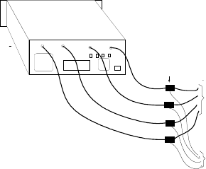
Connect the other end of the W2 coax to the antenna connection on the back of the MXU console
as illustrated in Figure 4.3.2-2. Repeat for the other W2 coax. If the W2 coax is not of sufficient
length, refer to Appendix “B”.
Figure 4.3.2-2: NOMAD MXU Coax Connections
Fan Power
Supply
Fan
SIM Access Cover
Antenna 1 Antenna 2 Antenna 3 Antenna 4
Line 1 Line 2 Line 3 Line 4
SURGE
SUPPRESS ORS (4)
Bare Copper Wire
to EARTH
Coax to
Antennas
DRAFT COPY
NOMAD MXU Installation Manual 3:36 PM 02/12/99
DRAFT COPY 18
4.3.3 Power Connection
WARNING
Improper AC Mains Grounding Hazard
Ensure the AC mains power is properly grounded before connecting the equipment. Failure to
observe this warning can result in serious injury or death by electrocution.
Step 10. Using the correct power cord, connect the local power (??????110 VAC, 60 HZ or 230 VAC 50
HZ) to the MXU’s back panel’s power outlet. If the local power wall socket is not the correct
configuration for the supplied power cord, Go back to Section 4.3.2, step 2.
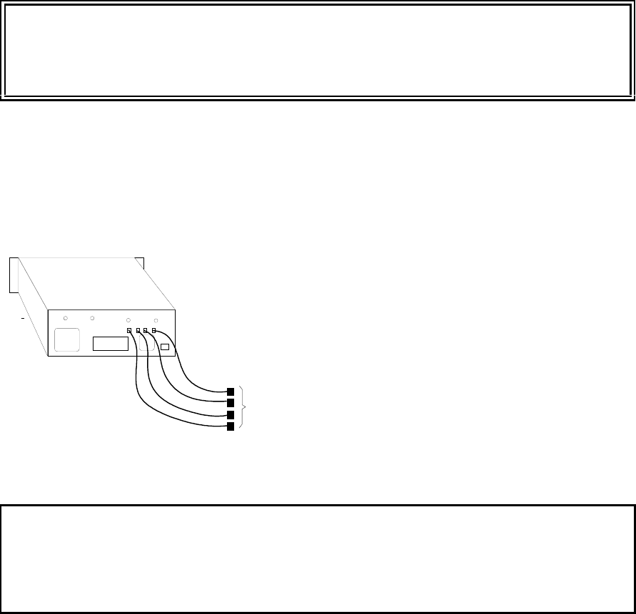
4.3.4 PSTN to MXU Inter-Connections
Figure 4.3.4-1: MXU PSTN Interconnections
CAUTION
Digital Telephone Line
Ensure the telephone lines are capable of accepting analog signals. DO NOT attempt to connect
to a digital telephone line – equipment damage will result.
Using the four supplied telephone lines, connect the local PSTN to MXU back panel connectors Lines 1,2,3
and 4. NOTE: If the PSTN socket is not a RJ-11 type, refer to the “Pre-Installation Check List”,
Appendix “A”, Check 5.
Fan Power
Supply
Fan
SIM Access Cover
Antenna 1 Antenna 2 Antenna 3 Antenna 4
Line 1 Line 2 Line 3 Lin e 4
Connect to
PSTN

DRAFT COPY
NOMAD MXU Installation Manual 3:36 PM 02/12/99
DRAFT COPY 19
5 Checkout
CAUTION
Antenna Radiation Emission
As a precaution maintain a minimum distance of 30 centimeters (12 inches) from the antenna
array while in operation.
5.1 Initial Power Up Checks
You are now ready to power on the MXU and start the checkout sequence.
Power on the NOMAD MXU Console by pushing the”ON” push button.
In less than 2 seconds, the “Power LED” should light.
If the “Power Up “ LED does not light
STOP: Go to section 6.1 “Power Problems” section of this document.
DRAFT COPY
NOMAD MXU Installation Manual 3:36 PM 02/12/99
DRAFT COPY 20
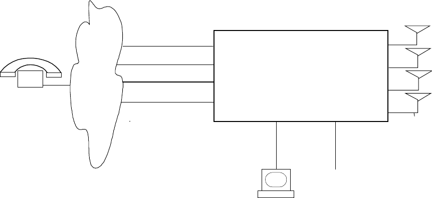
5.2 PSTN Check
Figure 5.2-1: PSTN Test Setup
Three to five minutes after the Power LED lite, the Ready LED should light.
The Power LED = ON and Ready LED = ON, indicates the MXU has successfully completed its internal
self testing and at least one channel is capable of passing traffic between the PSTN and the Iridium System.
NOTE: This does not insure all four channels are capable of passing traffic. Continue on with the checkout
procedure.
Figure 5.2-1 illustrates the setup to initially test and determine if the PSTN is correctly connected to the
NOMAD MXU console. Using the test telephone attached to the PSTN complete the following steps.:
Line # 1 Telephone connection check:
Dial the phone number for MXU line #1 and verify the following:
1. Listen on the test phone and verify the MXU picks up the phone.
2. Observe the MXU front panel and verify the “Line 1” LED” lights.
3. Listen on the test phone and verify the modem tone occurs, (may take up to 1 minute).
4. Hang up the test phone, the MXU front panel “Line 1” LED should go out.
If steps 1,2,3 and 4 happened, the connection is valid.
Go to “Line # 2 Telephone connection check”
If steps 1,2,3 and 4 are not correct the telephone line may be at fault”
Go to section 6.2 “Telephone Problems”
Line # 2 Telephone connection check:
Dial the phone number for MXU line #2 and verify the following:
1. Listen on the test phone and verify the MXU picks up the phone.
2. Observe the MXU front panel and verify the “Line 2” LED” lights.
3. Listen on the test phone and verify the modem tone occurs, (may take up to 1 minute).
4. Hang up the test phone, the MXU front panel “Line 2” LED should go out.
If steps 1,2,3 and 4 happened, the connection is valid.
Go to “Line # 3 Telephone connection check”
RS232
NOMAD
MXU
Analog
Phone Lines
Local
PSTN
110/230VAC
50/60 Hz.
Optional, Local
Admin or Monitor
PC
Line #1
Line #2
Line #4
Line #3
Test
Phone
DRAFT COPY
NOMAD MXU Installation Manual 3:36 PM 02/12/99
DRAFT COPY 21
If steps 1,2,3 and 4 are not correct the telephone line may be at fault”
Go to section 6.2 “Telephone Problems”
Line # 3 Telephone connection check:
Dial the phone number for MXU line #3 and verify the following:
1. Listen on the test phone and verify the MXU picks up the phone.
2. Observe the MXU front panel and verify the “Line 3” LED” lights.
3. Listen on the test phone and verify the modem tone occurs, (may take up to 1 minute).
4. Hang up the test phone, the MXU front panel “Line 3” LED should go out.
If steps 1,2,3 and 4 happened, the connection is valid.
Go to “Line # 4 Telephone connection check”
If steps 1,2,3 and 4 are not correct the telephone line may be at fault”
Go to section 6.2 “Telephone Problems”
Line # 4 Telephone connection check:
Dial the phone number for MXU line #4 and verify the following:
1. Listen on the test phone and verify the MXU picks up the phone.
2. Observe the MXU front panel and verify the “Line 4” LED” lights.
3. Listen on the test phone and verify the modem tone occurs, (may take up to 1 minute).
4. Hang up the test phone, the MXU front panel “Line 4” LED should go out.
If steps 1,2,3 and 4 happened, the connection is valid.
Go to “Section 5.3, Monitor Station Checkout”
If steps 1,2,3 and 4 are not correct the telephone line may be at fault”
Go to section 6.2 “Telephone Problems”
5.3 Monitor Station Check (Optional)
It is possible to configure a user supplied personal computer (PC) to interface with the NOMAD MXU
console through the RS232 connector on the front panel, This will enable the user to monitor MXU
activities and retrieve diagnostic logs from the MXU. For details on setup and operation of the monitor
station refer to the administrative manual.
5.4 Satellite Link Checks (Optional)
If the “Ready Light came on during the power up sequence described in section 5.1, at least one channel
exists between the NOMAD MXU console and the Iridium satellites. There are several ways to determine
if all RF channels, antenna, coax cables, and the RF side of the MXU console are operating correctly.
Methods 1 and 2 are preferred for verification but method three can be used for verification or isolation of
the problem to either the antenna and coax, or to the RF portion of the MU console.
1. If the user setup the monitor station, described in section 5.3, the diagnostic logs can be retrieved and
the signal strength between the satellites and the MXU can be verified. Refer to the Administration
Manual for details.
2. If the user did not setup the monitor station, the Gateway can retrieve the diagnostic logs, over the
PSTN modem connection, and inform the user of the status of the Iridium channels. Refer to the
Administration Manual for details. If one of the channels is not present or has a weak signal refer to
section 6.3.
3. If the Ready LED on the MXU’s front panel came on, all four RF channels can be verified without a
diagnostic log as follows.
First Step: We need to determine the good and bad RF channels as follows:
a. Power Down the MXU
b. Disconnect all the antenna cables but one, from the back of the MXU.
DRAFT COPY
NOMAD MXU Installation Manual 3:36 PM 02/12/99
DRAFT COPY 22
c. Power on the NOMAD MXU.
d. If the Ready LED comes on within 3 to 5 minutes mark the Coax cable and MXU connector as
good. Else mark both “questionable”.
e. Repeat steps a,b,c & d for each of the three remaining channels.
Second Step: We need to determine which “Questionable” cables are bad.
a. Power Down the MXU
b. Disconnect all the antenna cables from the back of the MXU.
c. Connect the questionable coax from a bad channel to a good MXU channel.
d. Power on the NOMAD MXU.
e. If the Ready LED comes on within 3 to 5 minutes mark the questionable Coax cable good. Else
mark the cable bad.
f. Repeat steps a,b,c d & e for each of the three remaining “questionable” cables.
TO REPAIR ANTENNA/ COAX CABLES, REFER TO Section 6.3.
Third Step: We need to determine which “Questionable” MXU RF channels are bad.
a. Power Down the MXU
b. Disconnect all the antenna cables from the back of the MXU.
c. Connect a “good” coax to a “questionable MXU channel.
d. Power on the NOMAD MXU.
e. If the Ready LED comes on within 3 to 5 minutes mark the questionable MXU Channel “good”.
Else mark the RF Channel “bad”.
f. Repeat steps a,b,c d & e for any remaining “questionable” MXU RF channels.
NOTIFY THE GATEWAY OF ANY BAD MXU RF CHANNELS.
5.5 Request Initialization
When all the initial checks are OK, call gateway and request initialization
DRAFT COPY
NOMAD MXU Installation Manual 3:36 PM 02/12/99
DRAFT COPY 23
6 Trouble Shooting Guidelines
CAUTION
Replaceable Battery
Danger of explosion if battery is incorrectly replaced.
Replace only with the same or equivalent type recommended by the manufacturer.
Dispose of used batteries according to the manufacturer’s instructions.
6.1 Power Problems
NOMAD MXU POWER UP SERVICE PROBLEMS
Problem(s) Possible Cause(s) Solution(s)
Power Up LED does
not Light. Verify MXU power cord is
connected to the building power
outlet.
Insert plug into outlet. If the plug does
not fit the outlet, refer to Section 4.3.3,
Step 10, or section 4.3.1, Step 2, or
Appendix “A” Pre-Installation Checklist,
Check 10.
No power at the building outlet Verify power, must be
90 to 135 VAC, 47 to 63Hz,: or,
180 to 265VAC, 47 to 63 Hz
Building Circuit Breaker opens, or
Building Fuse blows. Verify the building power outlet is
correctly polarized, refer to Section
4.3.1, Step 1, or Appendix “A”, Pre-
Installation Checklist, Check 9
.
6.2 Telephone Line Problems
NOMAD MXU TELEPHONE SERVICE PROBLEMS
Problem(s) Possible Cause(s) Solution(s)
Test Step 1: Can not
verify the MXU picks up
the phone.
Telephone line is not connected Connect per section 4.3.4
Incorrect phone jack, can not
connect the phone line. Refer to Appendix “A”, Pre-Installation
Checklist, Checks 5 and 6.

DRAFT COPY
NOMAD MXU Installation Manual 3:36 PM 02/12/99
DRAFT COPY 24
NOMAD MXU TELEPHONE SERVICE PROBLEMS
Problem(s) Possible Cause(s) Solution(s)
.Bad telephone line. Remove the telephone cable plug from
the back of the MXU and connect it to
a 2 wire analog phone, Note: you may
need a RJ11 adapter. Make a test
phone call between the test telephone
and the 2 wire analog phone. NOTE:
Do not connect a phone directly to
the MXU, it will not work.
Test Step 2: MXU front
panel “Line n LED” does
not light when the MXU
picks up the phone
If the Power On LED is lite, and
the MXU phone pickup is heard,
and the modem tone is heard, but
the Line LED is not lite,
Probably a bad LED
Contact the Gateway to determine the
repair procedure. NOTE: The MXU
probably can still be initialized and
made operational.
Test Step 3: No modem
tone occurs, (may take up
to 1 minute).
If the Power On LED is lite, and
the MXU phone pickup is heard,
and the Line LED is lite,
but no Modem tone.
Probably a bad MXU modem
Contact the Gateway to determine the
repair procedure. NOTE: Without the
NOMAD MXU modem the unit can not
be controlled remotely.
Test Step 4: The Line n
LED does not go out
when the test phone is
hung up.
PSTN non hanging up. Disconnect the telephone line at the
MXU and verify the Line “n” LED goes
out. If so there is a PSTN problem,
6.3 Antenna Line Problems
NOMAD MXU ANTENNA SERVICE PROBLEMS
Problem(s) Possible Cause(s) Solution(s)
DRAFT COPY
NOMAD MXU Installation Manual 3:36 PM 02/12/99
DRAFT COPY 25
APPENDIX “A” –User Site, Pre Installation Check List
PURPOSE: The purpose of this checklist is to prevent problems during the installation phase. This
checklist is not an installation guide, it should be completed before the NOMAD MXU equipment arrives
on site. Figure A1 below is a summary of the checklist.
Typical User MXU Installation.
NOMAD MXU CONSOLE
Check 1: Determine the environment of the NOMAD MXU console will be
+15oC to +35oC and a maximum 80% relative humidity , non-condensing. ______
ANTENNAS
Check 2: Location of Antennas
Clear line of sight, Horizon to Horizon___________________________________
Check 3: Verify an 8 meter outside antenna coax (W1) is of sufficient length___________
If the length is not sufficient, see Appendix “B”.
Check 4: Verify 1.5 meter inside antenna coax (W2) is of sufficient length_____________
If the length is not sufficient, see Appendix “B”
PSTN
Check 5, Verify local PSTN Connections will accept PJ11 type plugs_________________
Cables supplied with the MXU, have RJ11 plugs on each end.
If the PSTN receptacles are not RJ11 types, adapters have to be procured by the user.
Check 6: Verify all four sets of phone lines are 2 wire analog_________________________
Line 1
Line 2
Line 3
Line 4
Channe l 1
Channel 2
Channe l 3
On
Ready
Power
Channel 1 Initiate
Power
Down
Sequenc e
Control Interface
Example:
110VAC
50/60 HZ
, Null Modem Cable
(RS232, Customer Furnished)
Power Cord
Check 1:
Determine location of the console
(+15 C to +35 C, Max 80% Relative Humidity, Non-Condensing)
Check 2:
Determine location of the antennas
( Clear Line of Sight, Horizon to Horizon)
Check 3:
Length of Outside Antenna Coax
Check 4:
Length of Inside Coax
Check 5,
Type of PSTN Connectors (RJ11)
Check 6,
Verify phone lines are 2 wire analog
Check 7,
Verify phone line with Modem call to Gateway
Check 10
, Verify correct power cord has been ordered.
Check 11
, Monitor Station Requirements
To
Local
PSTN
NOMAD
Console
Lighting
Arrestors
Lighting Rod
Monitor
Station
Check 8:
Verify correct power
Check 9:
Verify power outlet is grounded
Check 12,
Null Modem Cable available
oo
DRAFT COPY
NOMAD MXU Installation Manual 3:36 PM 02/12/99
DRAFT COPY 26
If not the MXU will not function.
Check 7: Verify all four phone lines, can make modem calls between the users location and
the Gateway. ________________________________________________________
If not, the MXU can not be controlled from the gateway and must be configured
at the factory.
POWER
Check 8: Verify the Power Voltage is 90 to 135 VAC, 47 to 63Hz,: or,
180 to 265VAC, 47 to 63 Hz____________________________________________
if one of these two voltages is not available, the MXU will not work.
Check 9: TO REDUCE THE RISK OF ELECTRIC SHOCK, HAVE A CERTIFIED ______
ELECTRICAN VERIFY THE POWER OUTLET IS CORRECTLY GROUNDED.
If the outlet is not properly grounded, have the electrician replace it.
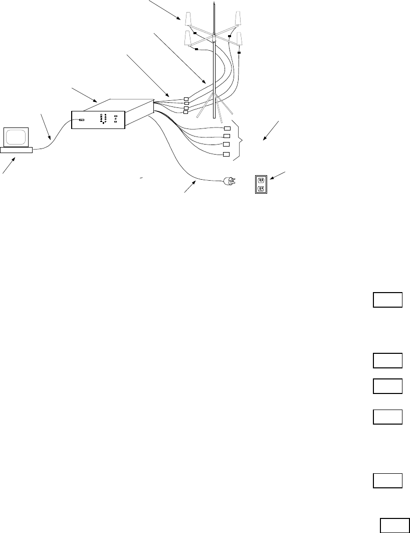
Check 10 Verify the correct AC Power Cord has been ordered_________________________
If a power cord was not specified, the user will receive the power cord
illustrated below.
The correct power cord is the responsibility of the user. A possible source of power
cords can be contacted at the following website. http://www.panelcomponents.com
MONITOR STATION (Optional, User Supplied)
Check 11, Verify the configuration of the Monitor Station PC (user supplied) ____________
IBM compatible a Pentium class PC
at least 50 MB of free disk space,
Microsoft NT 4.0 installed
NT Service Pack Three installed
CDROM drive (required to install the NOMAD MCM program)_______________
Check 12: Verify, Null Modem Cable per following schematic. (user supplied)___________
Transmit Data (2)
Receive Data (3)
Request To Send (7)
Clear To Send (8)
Data Set Ready (6)
Ground (5)
Data Carrier Detect (1)
Data Terminal Ready (4)
(2) Transmit Data
(3) Receive Data
(7) Request To Send
(8) Clear To Send
(6) Data Set Ready
(5) Ground
(1) Data Carrier Detect
(4) Data Terminal Ready
Building
Ground
Wide Blade
110VAC_Low
Narrow Blade
110VAC_High
MXU
Connector To Wall Outlet
DRAFT COPY
NOMAD MXU Installation Manual 3:36 PM 02/12/99
DRAFT COPY 27
APPENDIX “B” – Coax Cable Options
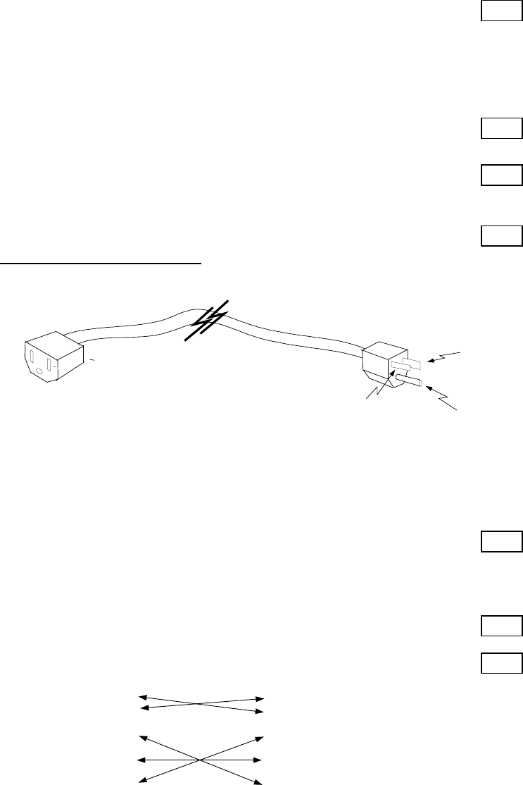
Figure B1: Standard cable lengths as shipped with the NOMAD MXU.
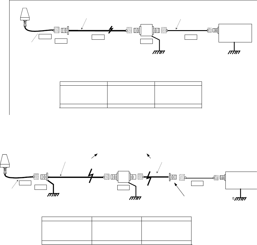
Figure B2: Custom cable lengths to be ordered by the user.
MXU
W1-A
0.1 dB
SURGE
PROT.
Plug
Aero
AT1621-73W-TNCF
Polyphaser
IS-CLF50LN
Jack
Jack
0.1 dB
Type N Type N
Jack
Plug Jack (Bulk Head)
Type N
0.3 m (1 ft.)
LMR-240
TNC
0.1 dB
W3
Earth for
Lighting Protection
Plu
g
TNC
W2
0.5 dB
Plug TNC
Plug
W1-B
Antenna Component Length dB Loss
W3 Antenna Lead-in 0.3 Meters (1 ft) NOTE 1 0.1 dB
Outside Coax Connector 0.1 dB
W1 = W1A + W1B ( NOTE 2) X Meters NOTE 3 1.5 dB
Lighting Surge Protector 0.1 dB
W2 Inside Coax 1.5 Meters (5 ft) NOTE 1 0.5
Totals X + 1.8 Meters 2.3 dB Loss
Non - Standard Length / Type Cables
NOTE 3:
The allowable length of the W1 cable, or W1A + W1B cables, is based on dB loss.
The total dB loss through W1, or W1A + W1B, and related connectors and adapters must be less
than 1.5 dB.
NOTE 1:
Supplied coax cables W3 and W2 must be used in the installation to serve as strain
reliefs; else, damage to the antenna or the antenna connections on the MXU will occur..
NOTE 2:
Depending on the installation, W1 and or W3 may be too short. If so, custom coax cable
W1, or two custom cables W1A and W1B, may be procured from a cable vendor.
Type of coax depends on the length Type of coax depends on the length
PlugJack (Bulk Head)
Type N
Bulk head connector to be used as the
anchor for the strain relief.
W1A + W1B must total less than 1.5 dB of loss.
Plug
Jack
Antenna Component Length Db Loss
W3 Antenna Leadin 0.3 Meters (1 ft) 0.1 dB
Outside Coax Connector 0.1 dB
W1 Outside coax 8.0 Meters (26 ft) 1.5 dB
Lighting Surge Protector 0.1 dB
W2 Inside Coax 1.5 Meters (5 ft) 0.5
Totals 9.8 Meters or 32 Feet 2.3 db Loss
Summary, Standard Length / Type Cables
MXU
W1 W2
1.5 dB 0.5 dB
0.1 dB
SURGE
PROT.
Plug
Polyphaser
IS-CLF50LN
Jack
Jack
0.1 dB
Plug
Type N Type N TNC
Plug Jack
Plug Jack (Bulk Head)
8 m (26.2 ft)
LMR-400 or
1.5 m (4.9 ft)
LMR-240
0.3 m (1 ft.)
LMR-240
TNC
0.1 dB
W3
Earth for
Lighting Protection
Plug
Jack
Antenna