General Dynamics C4 Systems URC-200XCVR-V2 URC-200 (V2) Tactical, Line-Of-Sight, Radio User Manual 1
General Dynamics C4 Systems URC-200 (V2) Tactical, Line-Of-Sight, Radio 1
UserManual.wiki
>
General Dynamics C4 Systems
>
URC 200XCVR V2 User Manual
Users Manual
Navigation menu
Upload a User Manual
Namespaces
Wiki Guide
HTML
PDF
Info
Views
User Manual
Discussion / Help
Navigation
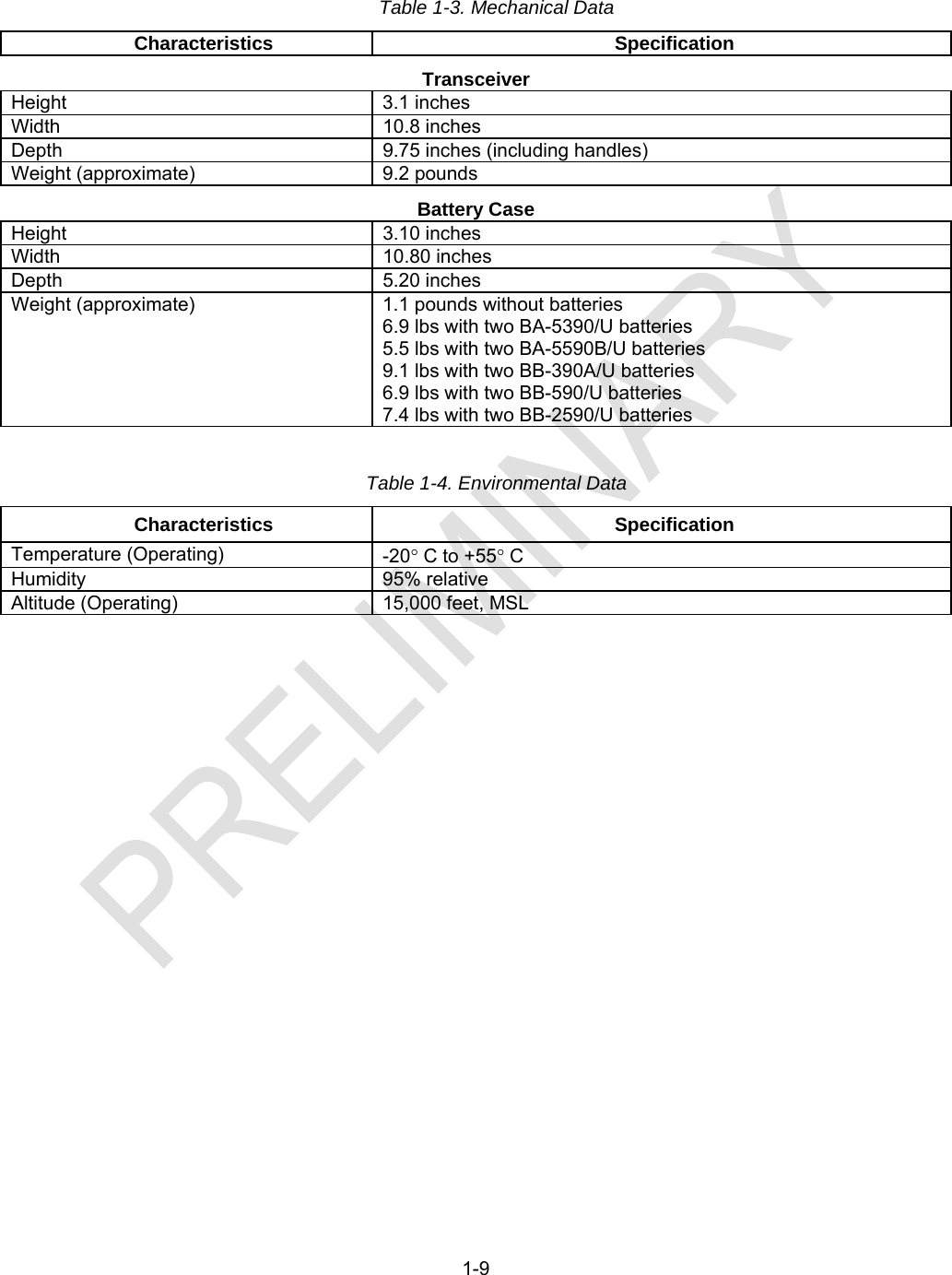
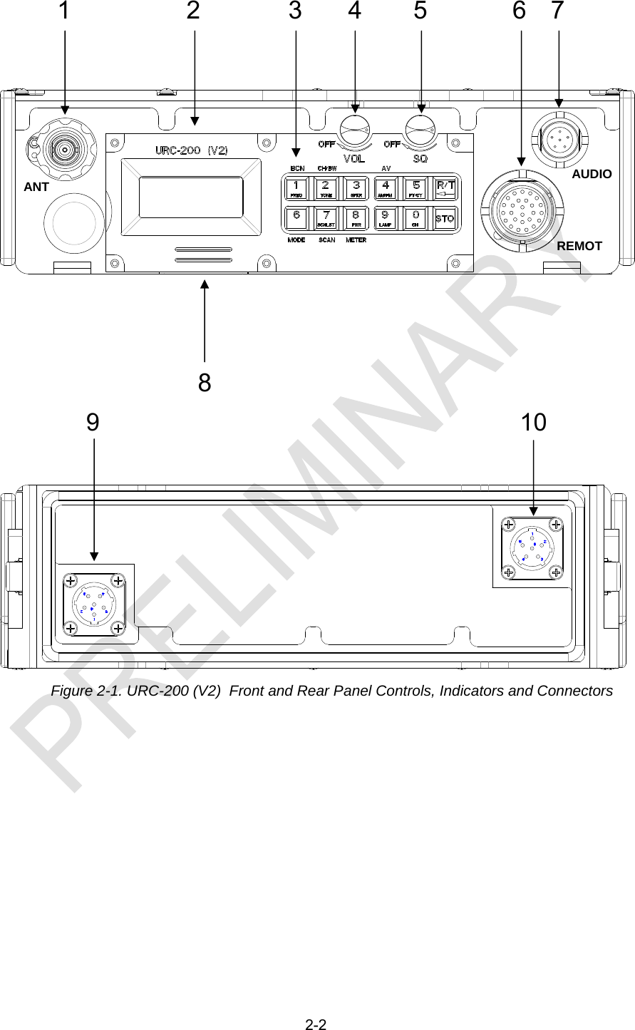
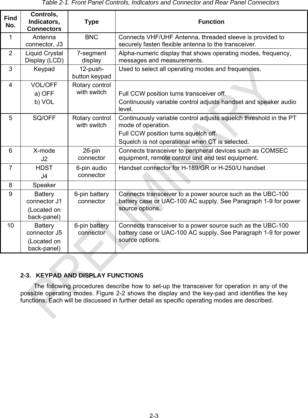
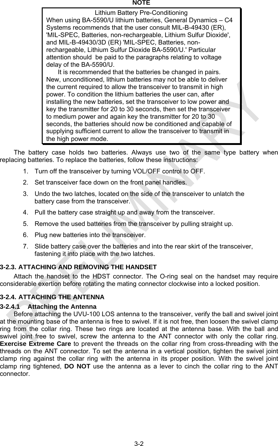
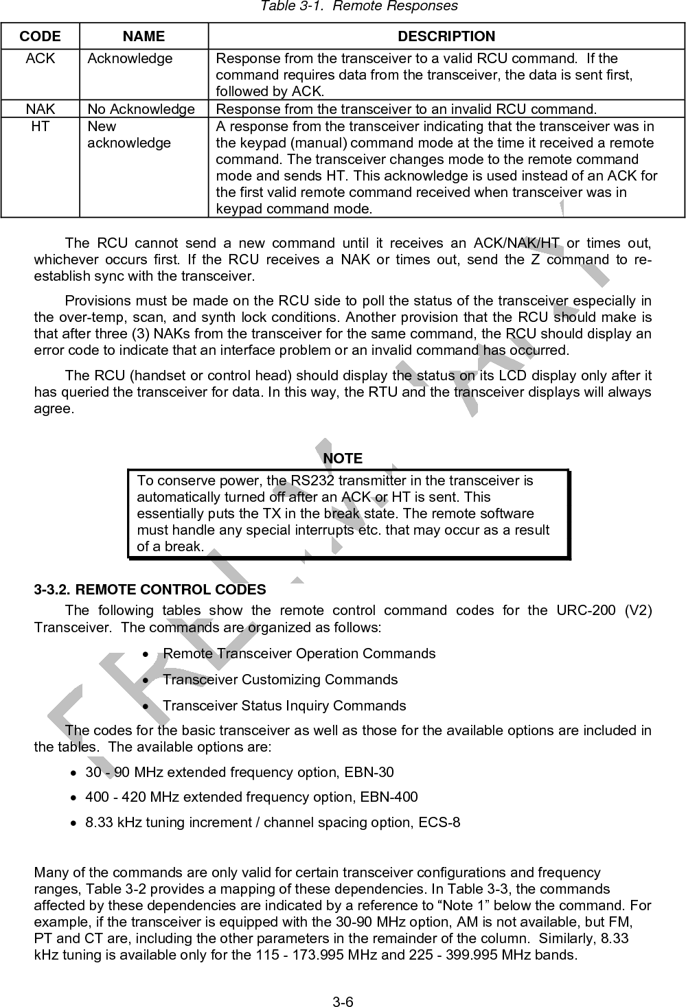
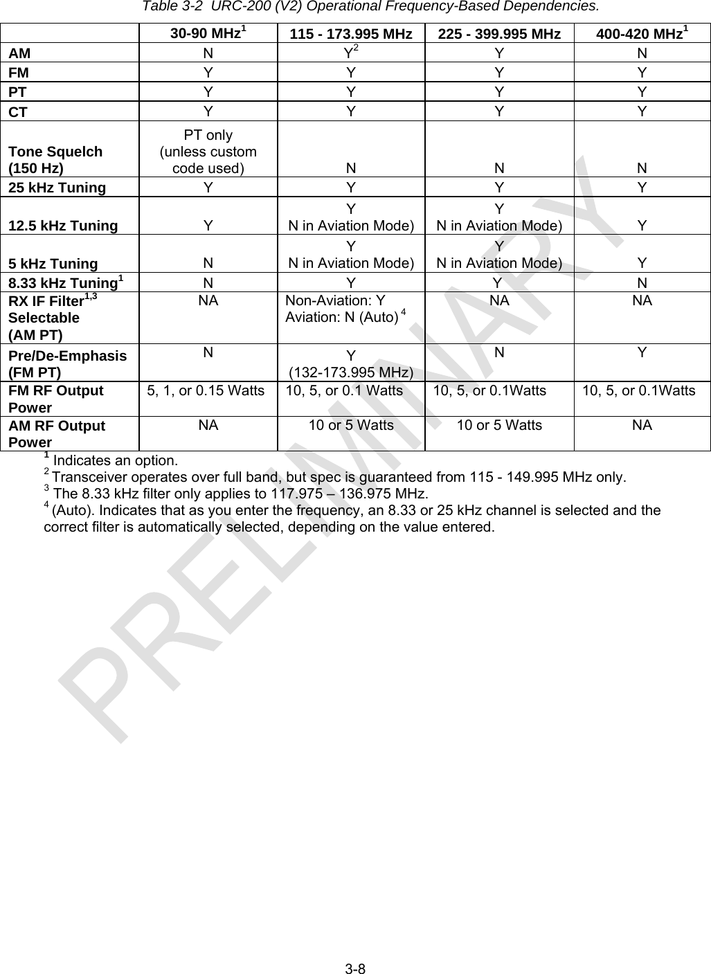
![1-1 SECTION 1. INTRODUCTION 1-1 GENERAL INFORMATION This manual provides operation and maintenance instructions for the URC-200 (V2) Radio Set shown in Figure 1-1. The radio set is a lightweight VHF/UHF transceiver providing AM/FM transmission and reception of non-secure voice or data in the frequency bands used in maritime, land, mobile and tactical line-of sight communications as well as military and civilian air traffic control operations. Secure communications can be achieved with an appropriate external encryption device and with the transceiver in the data [Cipher Text (CT)] mode. NOTICE The URC-200 (V2) is FCC certified in the 115-149.995 (AM) and115 - 173.995 (FM) bands. 1. The URC-200 (V2) transceiver is to be tuned only to those frequencies that the transceiver user, by law, is permitted to use. 2. Operation and tuning of the transceiver should be restricted to those users who are knowledgeable about which frequencies are authorized for use. 3. Transceiver operation on unauthorized frequencies is a violation of the law. 4. The capabilities of this transceiver allow users the freedom for authorized personnel to easily tune the transceiver. This allows the transceiver to work with other communication systems within the band, provided that the transceiver's tuned frequencies are permitted by regulation. Figure 1-1. URC-200 (V2) Transceiver Set](https://usermanual.wiki/General-Dynamics-C4-Systems/URC-200XCVR-V2/User-Guide-1196302-Page-9.png)
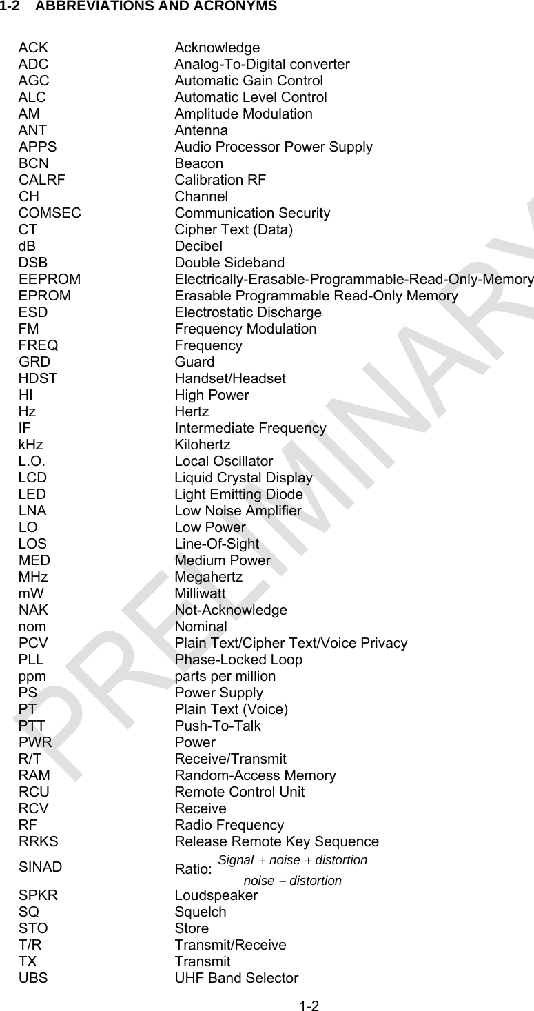
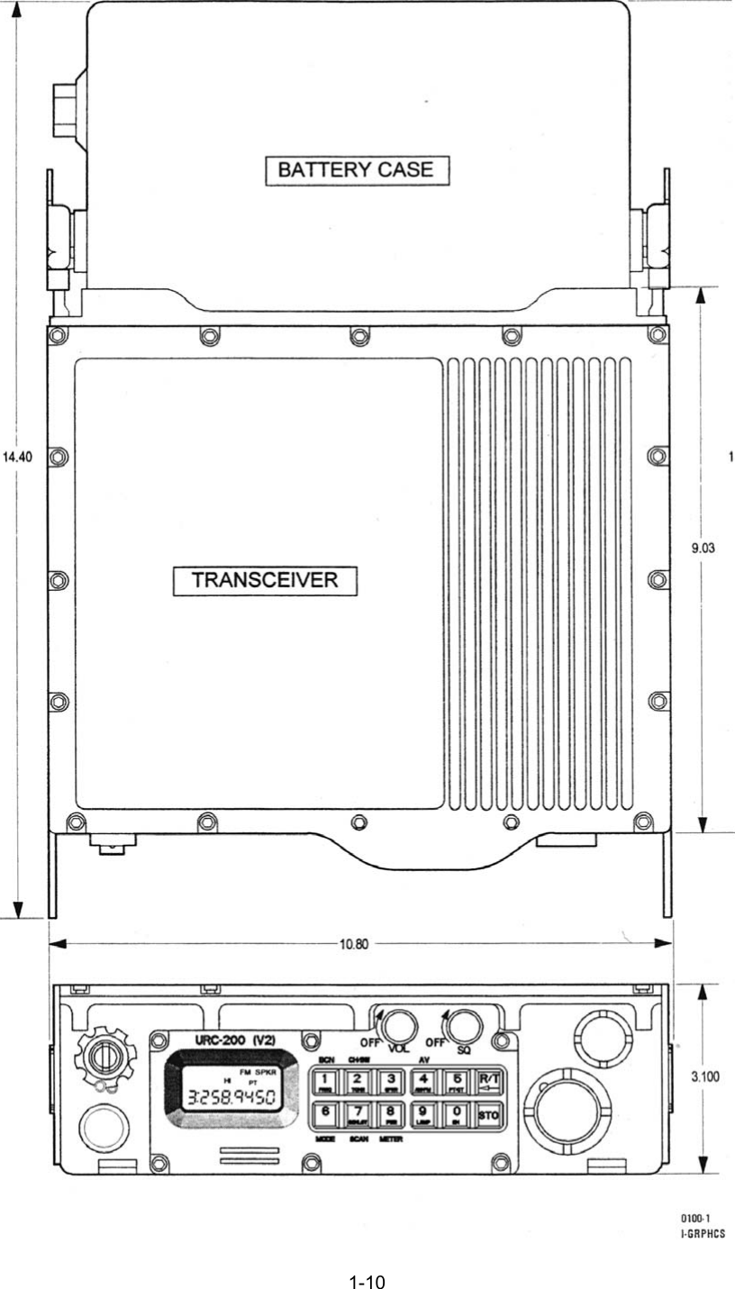
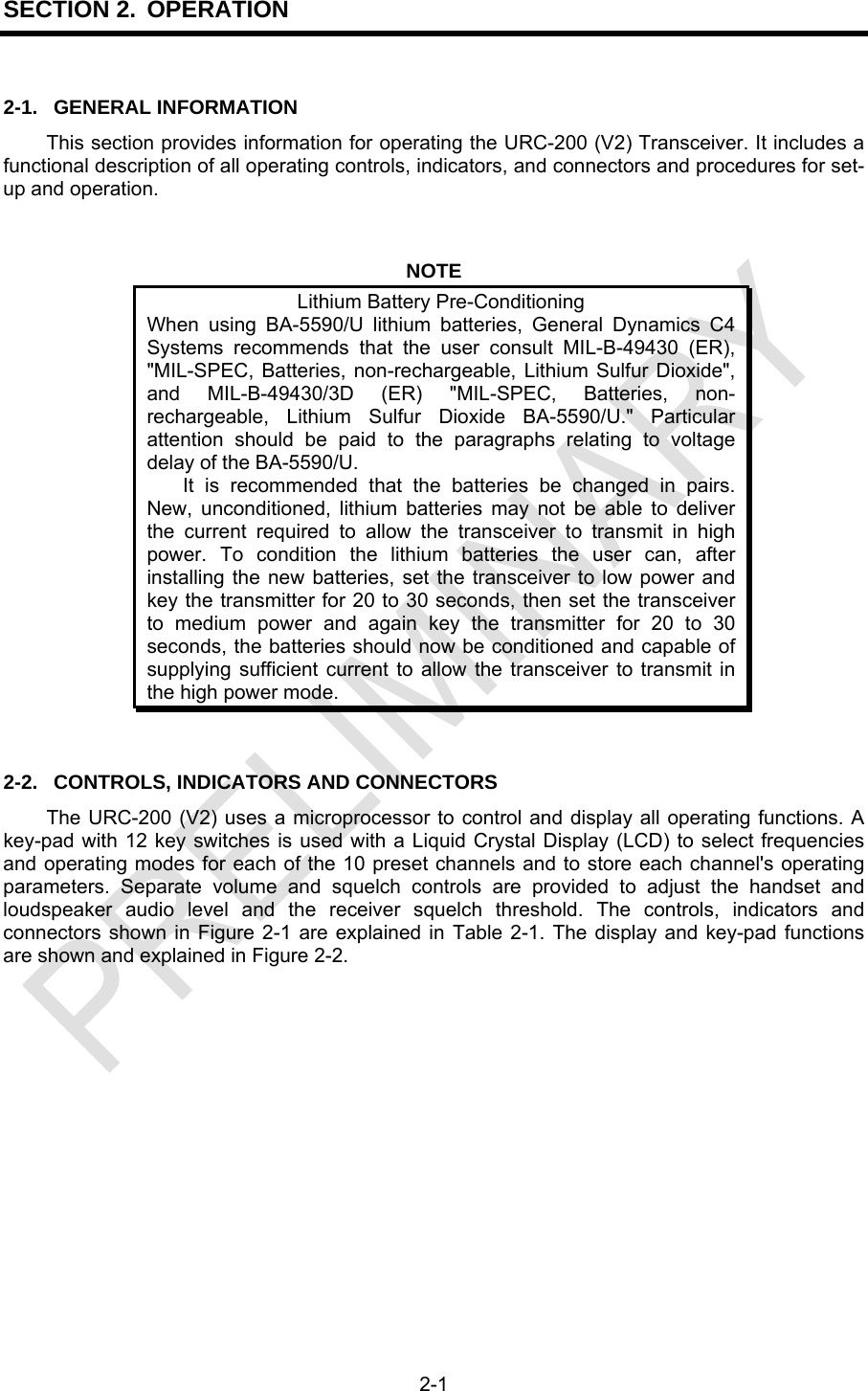
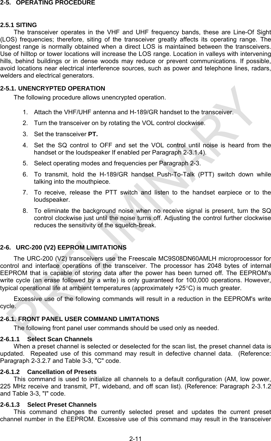
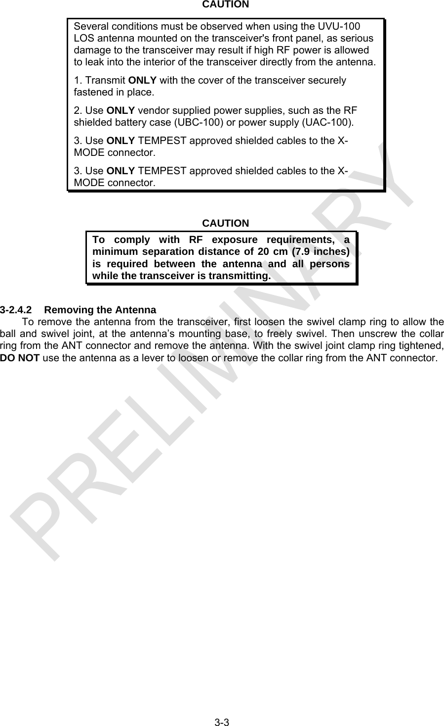
![2-4 Figure 2-2. Key-pad and Display Functions 2-3.1. NORMAL OPERATING MODE CONFIGURATION PROCEDURES The transceiver can be used for operation once it has been installed as described in Section 3. The transceiver is fully micro-processor-controlled from push button instructions selected at the front panel. The frequency is tuned either by selecting one of ten preset channels or by manually setting up the frequency on the LCD display. The preset frequencies may be stored in memory and may be changed any time the transceiver is turned on. The memory is maintained using an EEPROM that allows the presets to be stored even when the power is turned off or the transceiver batteries are removed. The EEPROM provides non-volatile memory and does not require the use of a keep-alive-voltage. In normal operating mode, the display will show the channel currently in use. The receive frequency and its associated data for that channel will be displayed while the transceiver is in receive mode. When the PTT is pressed, the transmit frequency and its associated data for that channel will be displayed. When transmitting, the transmit annunciator (TX) will be on. If the [R/T] key is pressed while in receive mode, the transmit frequency will be displayed, but the transceiver will still be receiving on the current channel's receive frequency. This situation is indicated by a blinking transmit annunciator. Pressing PTT at this point will put the transceiver in transmit mode, causing the transmit annunciator to come on steadily. When the PTT is released, the transceiver will go back into receive mode with the receive frequency and data for this channel being displayed.](https://usermanual.wiki/General-Dynamics-C4-Systems/URC-200XCVR-V2/User-Guide-1196302-Page-26.png)
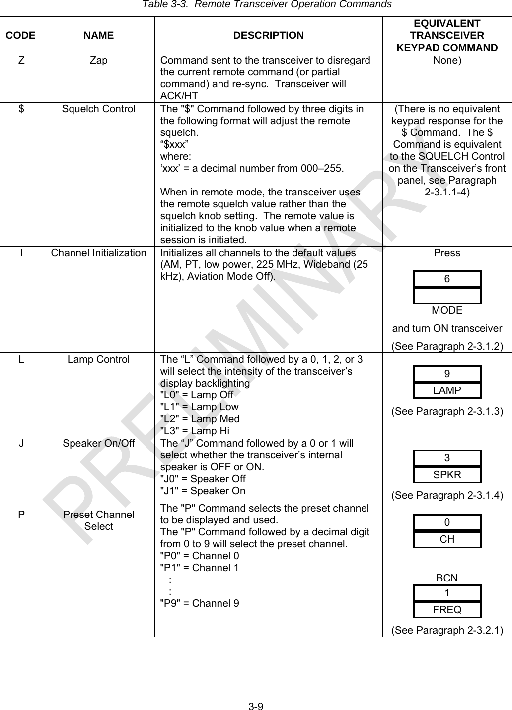
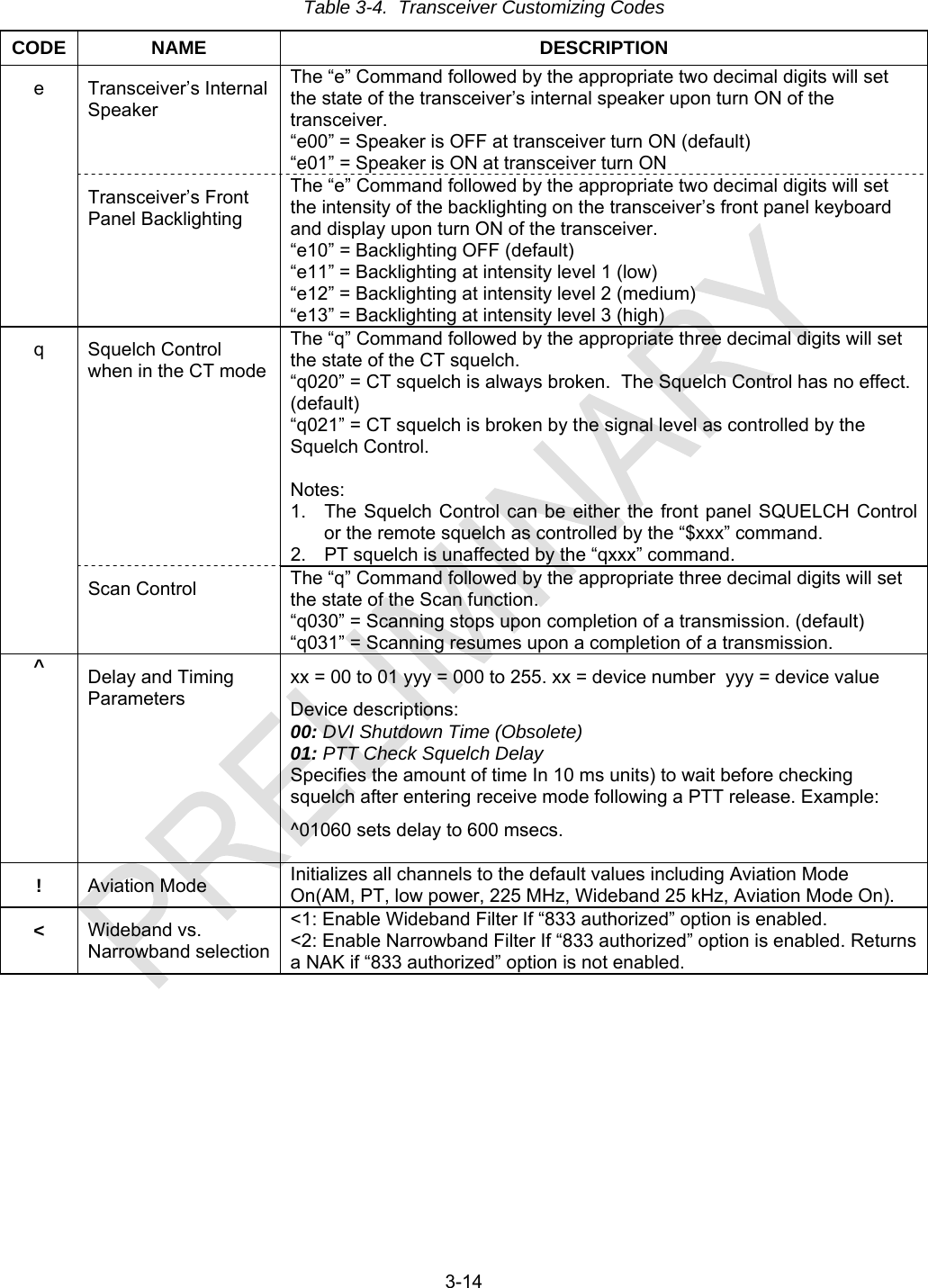
![2-5 2-3.1.1 Turning on the Unit Before performing the following steps, refer to Paragraph 2-2 for the location and functional description of the controls and indicators. 1. Make sure the transceiver set is connected for operation according to the installation instructions in Section 3. 2. Turn on the transceiver by turning the VOL control clockwise. 3. Set the VOL control for the desired volume (the SQ control must be in maximum counter clockwise position). To hear audio from the loudspeaker the speaker must be enabled per Paragraph 2-3.1.4. 4. Adjust the SQ control for the threshold by advancing clockwise slowly, just until the noise stops. Advancing the control further will reduce the sensitivity of squelch break. 2-3.1.2 Cancellation of Presets If the transceiver is powered-up while the [MODE] key is pressed, the transceiver will preset all the channel data for each channel to the default values (225 MHz, PT, AM, low power). It is this default condition that is used as the starting point for the following discussions. 2-3.1.3 Front Panel Illumination LAMPLAMP9 Pressing the [LAMP] key Controls the backlighting of the display and keyboard. Consecutive key strokes cycles through the four levels of brightness -- off No backlighting), low, medium, and high. When the transceiver is turned ON, the normal default from the factory is with the backlighting off. 2-3.1.4 Select Speaker ON/OFF SPKR PT MODE SPKR3 Pressing the [SPKR] key toggles the loudspeaker ON and OFF. When the [SPKR] key toggles the loudspeaker ON, the SPKR annunciator will appear in the upper right corner of the display. This is to signify that the loudspeaker has been turned ON. When the [SPKR] key toggles the loudspeaker OFF, the SPKR annunciator will disappear. When the transceiver is turned ON, the normal default from the factory is with the speaker off.](https://usermanual.wiki/General-Dynamics-C4-Systems/URC-200XCVR-V2/User-Guide-1196302-Page-27.png)
![2-6 2-3.1.5 Select Meter Mode Pressing the [MODE] key and then the [PWR] key activates the METER MODE. When the transceiver is in the receive mode, the display becomes a signal strength meter in the form of a bargraph, indicating the relative strength of the incoming receive signal. The meter will indicate a single bar at approximately -115 dBm and be full scale at approximately +3 dBm. When the transceiver is in the transmit mode (PTT pressed), indicated by the TX annunciator, the display becomes a power meter. At high UHF frequencies its accuracy is approximately 1 Watt per bar. As frequency decreases the power meter may be indicating a decrease in output power. This does not reflect a true reduction in output power. The true output power will be within specification across the frequency band. 2-3.2. SETTING PRESET CHANNELS This section describes how the preset channels are set. The transceiver is initially assumed to be set-up with the following conditions: low power, AM, plain text (PT), and a frequency of 225 MHz (for both receive and transmit), these are default values that are achieved when the transceiver is powered-up with the [MODE] key pressed, as described in Paragraph 2-3.1., above. The transceiver does not need to be set-up with these default settings; the following procedure applies for any settings except that the display examples will be different. 2-3.2.1 Select Preset Channels Pressing the [CH] key and then one of the numbered [n] keys, selects channel [n], the display shows the frequency and the attributes associated with that channel. This example shows the key-press sequence for selecting Preset Channel 1. Any channel from 0 to 9 may be selected.](https://usermanual.wiki/General-Dynamics-C4-Systems/URC-200XCVR-V2/User-Guide-1196302-Page-28.png)
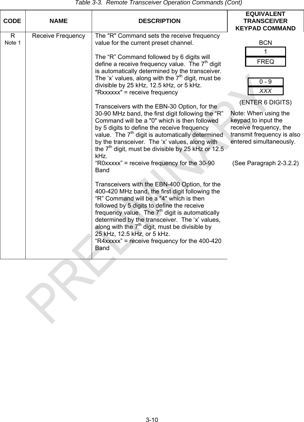
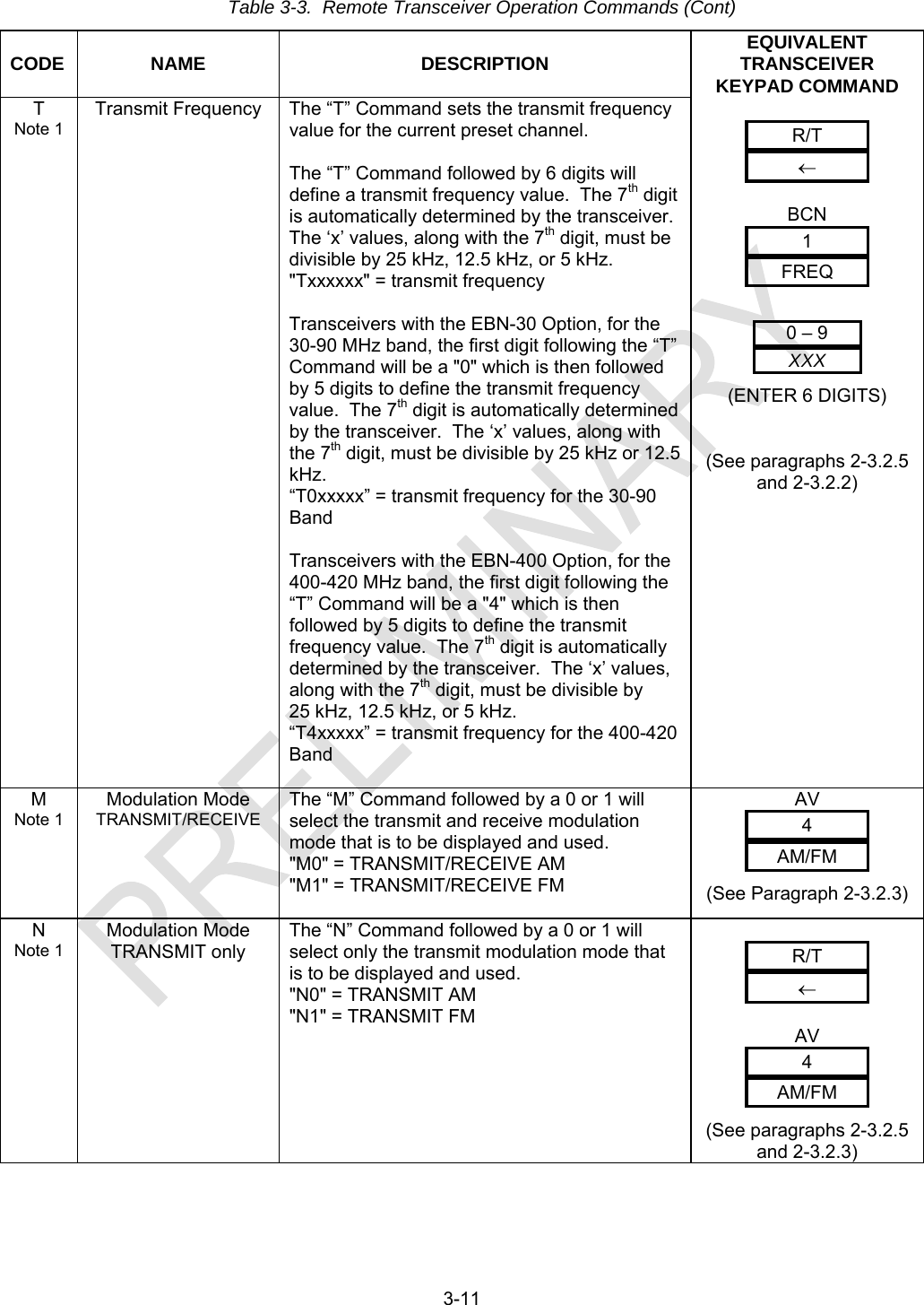
![2-7 2-3.2.2 Select Frequencies With a channel set-up as above, pressing the [FREQ] key (key-pad [1]) the transceiver will go into the "enter frequency" mode. The main display is blanked out except for the channel number (the number shown to the left the colon). The first digit of the desired frequency (1, 2, or 3) is pressed next and is displayed to the right of the colon. At this point, the transceiver will still be receiving on the same frequency as before. As the remaining digits of the desired frequency are entered, they will be displayed. Pressing the [<--] key will cause the last digit entered to be erased. If the first digit of the frequency is erased, the display will go back to showing the current receive frequency for this channel. When the sixth digit of the frequency is entered, the rest of the frequency is automatically determined, so the correct frequency is displayed and the transceiver is set to that frequency. Note that this can be used as a "manual" receive channel since the new frequency and any other associated data that has been changed will not be stored in memory until the [STO] key is pressed. If the Receive mode display is shown, entering the frequency will change the frequency for both Receive and Transmit frequencies. If the Transmit mode display is shown, entering the frequency changes only the Transmit frequency. If a flashing frequency is displayed on the transceiver’s screen, it may be an indication that an invalid frequency was entered into the transceiver. Reenter the frequency with a valid frequency. NOTE It is possible to enter a frequency in the 30 to 90MHz frequency band either through the transceiver’s front panel keypad or through the RS-232 ports on the J2 Remote Connector even though the 30 to 90MHz Enhancement Option is not installed in the transceiver. If a frequency in this range is entered and the 30 to 90MHz Enhancement Option is not installed, the frequency displayed on the transceiver’s front panel will flash. Also, the transceiver’s receiver and transmitter will not respond to the invalid frequency. By reentering the frequency with a valid frequency from the keypad or through the RS-232 ports the flashing display will cease and the transceiver will return to normal operation. 2-3.2.3 Select Modulation Mode AM/FMAM/FM4 AM FM Pressing the [AM/FM] key causes the transceiver to toggle between the AM and FM modulation modes for the currently-displayed channel. The new value will take effect immediately, as indicated by the annunciator, but will not be stored until the [STO] key is pressed. This select automatically applies to both sides of the preset channel, i.e., if AM is selected for the receive frequency, the transmit frequency is also AM. If the new modulation is AM and the transmit power level was MED, the power level will be automatically changed to HI (there is no AM MED level). If the Receive mode display is shown, the new modulation will apply to both the Receive and Transmit frequencies. If the Transmit mode display is shown, the new modulation will apply to the transmit frequency only.](https://usermanual.wiki/General-Dynamics-C4-Systems/URC-200XCVR-V2/User-Guide-1196302-Page-29.png)
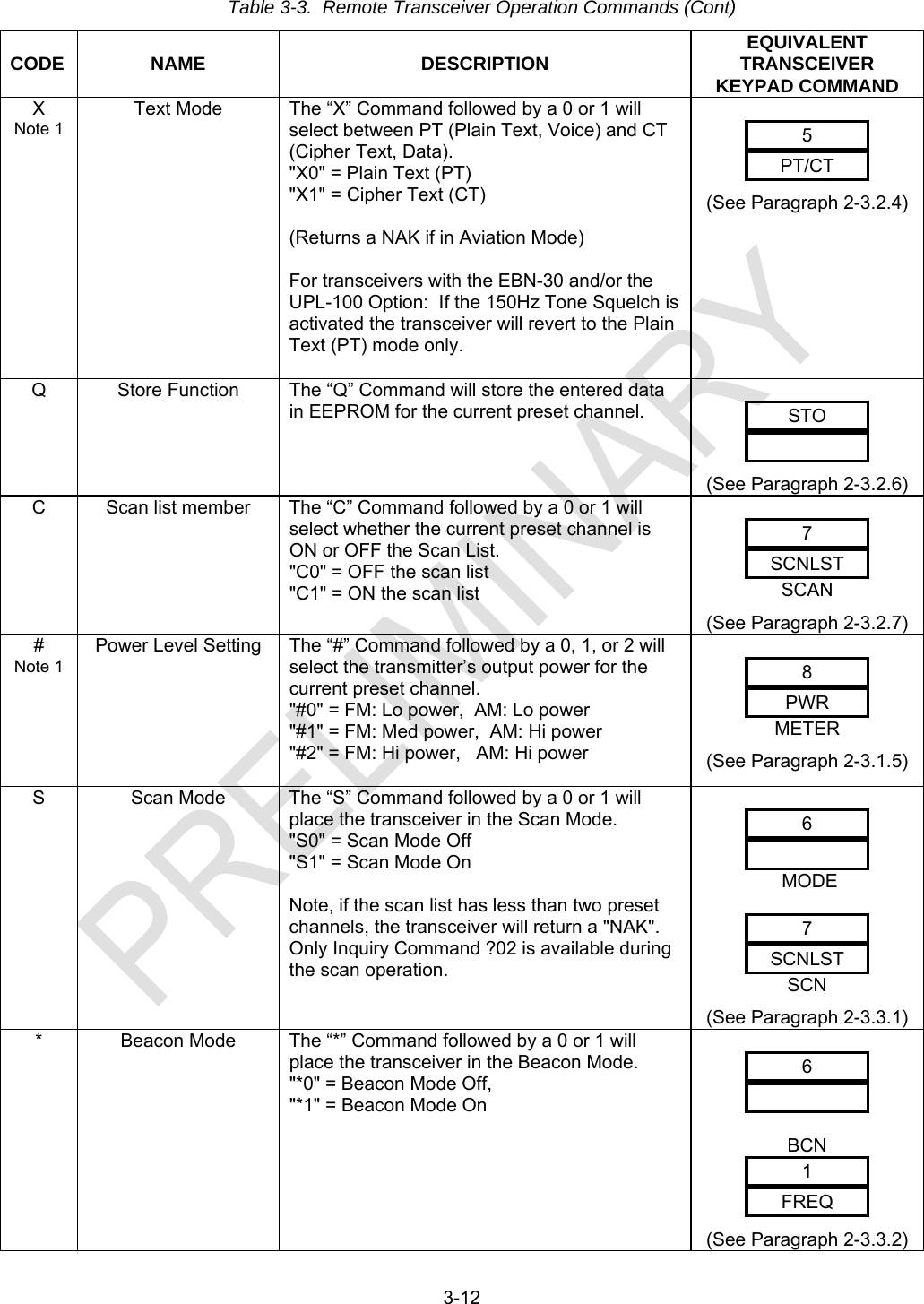
![2-8 2-3.2.4 Select Cipher Text/Plain Text Pressing the [PCV] key toggles between the plain-text and cipher-text (data) modes for the currently-displayed channel. The new value will take effect immediately when the [STO] key is pressed, as indicated by the annunciator. 2-3.2.5 Select Receive/Transmit Data R/TTX Pressing the [R/T] key switches the display between the receive frequency and its operating data for the selected channel and the transmit frequency and data for that channel. When the transmit data is displayed, the transmit annunciator, TX will blink. This key is also used as "back-space" when in the frequency select mode as described in Paragraph 2-3.2.2. 2-3.2.6 Storing Presets AM PT LO STO Pressing the [STO] key stores into memory the frequencies (receive and transmit), mode (PT/CT), modulation (AM/FM), transmit power (Tx), bandwidth, and scan list membership for the selected channel. 2-3.2.7 Select Scan Channels Pressing the [SCAN] key switches the selected preset channel on or off the scan list. The scan list must contain from two to ten of the preset channels before the scan mode can operate. The SCAN annunciator will light to indicate that this preset channel is on the scan list.](https://usermanual.wiki/General-Dynamics-C4-Systems/URC-200XCVR-V2/User-Guide-1196302-Page-30.png)
![2-9 2-3.2.8 Select Transmit Power Levels FM LO MED HI PWR8 Pressing the [PWR] key selects the transmit power levels for the transceiver. The power level annunciator will show the current setting. There are three power levels, LO, MED, and HI, available in the FM modulation mode and two power levels, LO and HI, when AM is selected. 2-3.3. SELECTING SPECIAL MODES The following paragraphs describe the procedures for special operating modes and functions of the transceiver. The special operating modes consist of the Beacon-, Guard-, and Scan-mode of operation. The special functions consist of Self Calibration of Receive Filters, Internal Voltage Measurements, and Return to Local Control from Remote operation. 2-3.3.1 Select Scan Mode Pressing the [MODE] key and then the [SCAN] key activates or de-activates the SCAN MODE. The scan mode causes the transceiver to cycle through the preset channels which are flagged as "scan channels", (see Paragraph 2-3.2.7), searching for an active channel I.e., one where incoming signal strength is sufficiently large to break squelch). While scanning, the display will show the channel that it is scanning. The transceiver will scan for 0.5 second on each selected scan channel. If an active channel is found, the transceiver will lock on that channel. If that channel becomes inactive for approximately four seconds, the transceiver will continue the scan with the next flagged channel. If the operator wishes to continue the scan while on a channel that is (or was) active, the [SCAN] key can be pressed. When an active channel is found, that channel's receive frequency will be displayed. If the push-to-talk key (PTT) is pressed while the transceiver is scanning, it will be ignored. If the PTT is pressed while a channel is active, the transceiver will go out of scan mode and into the normal mode using that channel, transmitting on that channel's preset transmit frequency. If the scan list has less than two channels, then the LCD will blink "Err-noSC" indicating the transceiver cannot enter the scan mode. To return to normal operation press the [CH] key followed by one of the 10 channel numbers [0 through 9]. The Scan Mode will be cancelled and the transceiver will go to the selected channel. When the scan mode is de-activated normally, by using the [MODE] plus [SCAN] keys, or by turning the transceiver OFF then ON, the transceiver will return to normal operation on the channel which was in use immediately prior to entering the SCAN MODE.](https://usermanual.wiki/General-Dynamics-C4-Systems/URC-200XCVR-V2/User-Guide-1196302-Page-31.png)
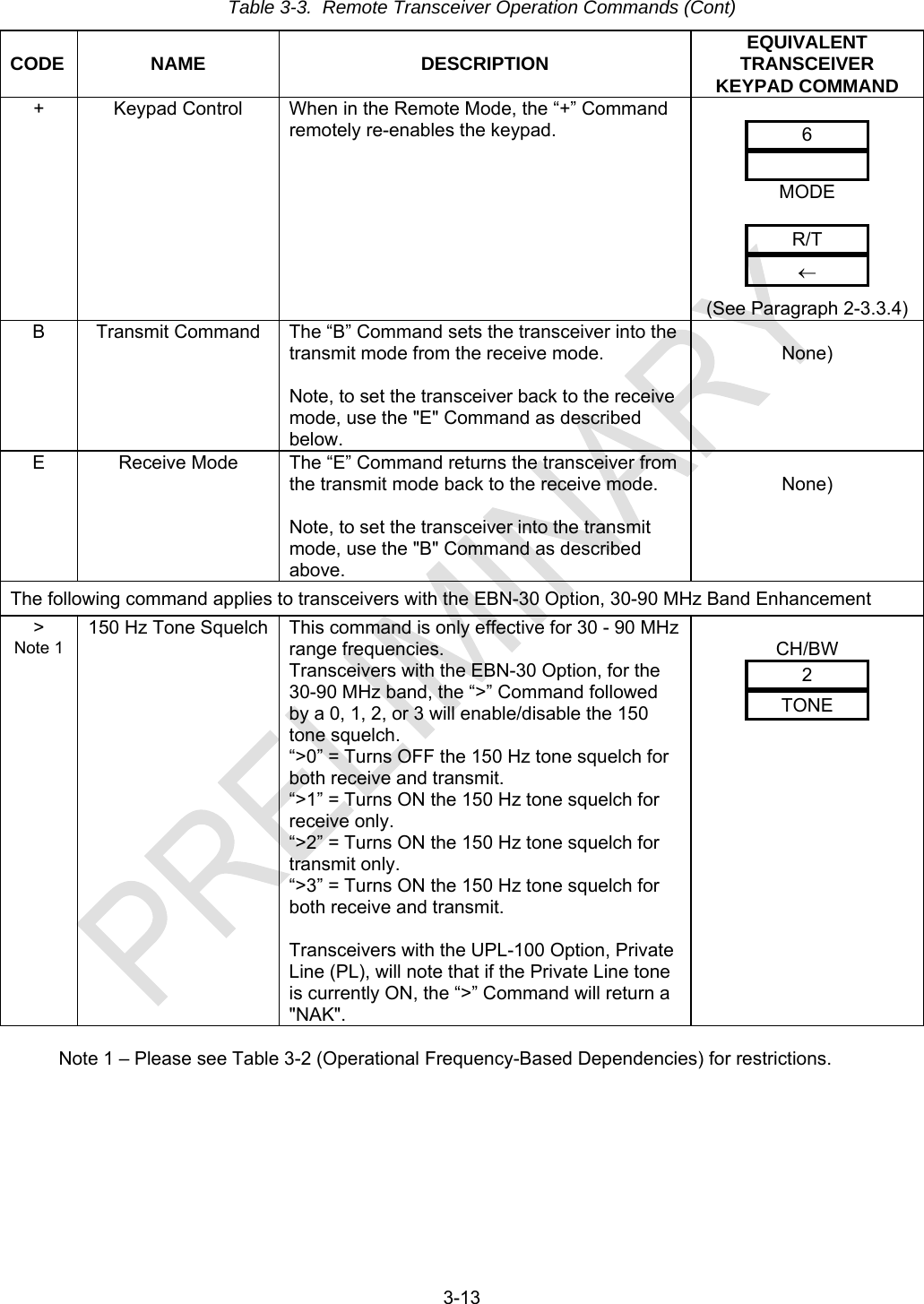
![2-10 2-3.3.2 Select Beacon Mode Pressing the [MODE] key and then the [BCN] key activates or de-activates the BEACON MODE. When the BEACON MODE is selected, the transceiver transmits a sweeping emergency audio signal on the selected channel frequency and in the selected modulation mode (AM or FM). The display alternately switches between the word "BEACON" and the selected channel information. No other operating functions are available when the BEACON is active. When the beacon mode is de-activated (by toggling the mode off or by turning the power OFF and then ON), the transceiver will go back into normal mode using the channel that was in use immediately prior to entering the BEACON MODE. 2-3.3.3 Internal Voltage Measurements With the transceiver set-up in the meter-mode per Paragraph 2-3.1.5., pressing the [R/T] key will display the voltages of the internal power supplies and of the batteries. The first time [R/T] is pressed the voltage of the +5Vdc supply - PS1 is displayed. Each consecutive press of [R/T] brings up the next supply; PS2: +12Vdc, PS3: -5Vdc, PS4: -12Vdc, PS5: +24Vdc (external power batteries), PS6: +70Vdc and AGC. NOTE The voltages displayed on the front panel are relative voltages. If a voltage/s appears to be too low or too high, measure the suspected voltage using a lab type voltmeter. The AGC level displayed is not a voltage. The AGC level is expressed as a digital value from 000 to 255. 2-3.3.4 Release from Remote Control Pressing the [MODE] key and then the [R/T] key returns the transceiver to local control from remote control. This sequence is called Release Remote Key Sequence (RRKS). This key sequence has no effect if the transceiver is not in the remote control mode. There is no on-screen indication that the transceiver is back in local mode. 2-4. ECS-8 8.33 KHZ OPTION This is the 8.33 kHz tuning increment / channel spacing option. The features of this option are only available if this option has been installed. If your transceiver has this option installed, refer to Section 5 for detailed information and operating procedures.](https://usermanual.wiki/General-Dynamics-C4-Systems/URC-200XCVR-V2/User-Guide-1196302-Page-32.png)
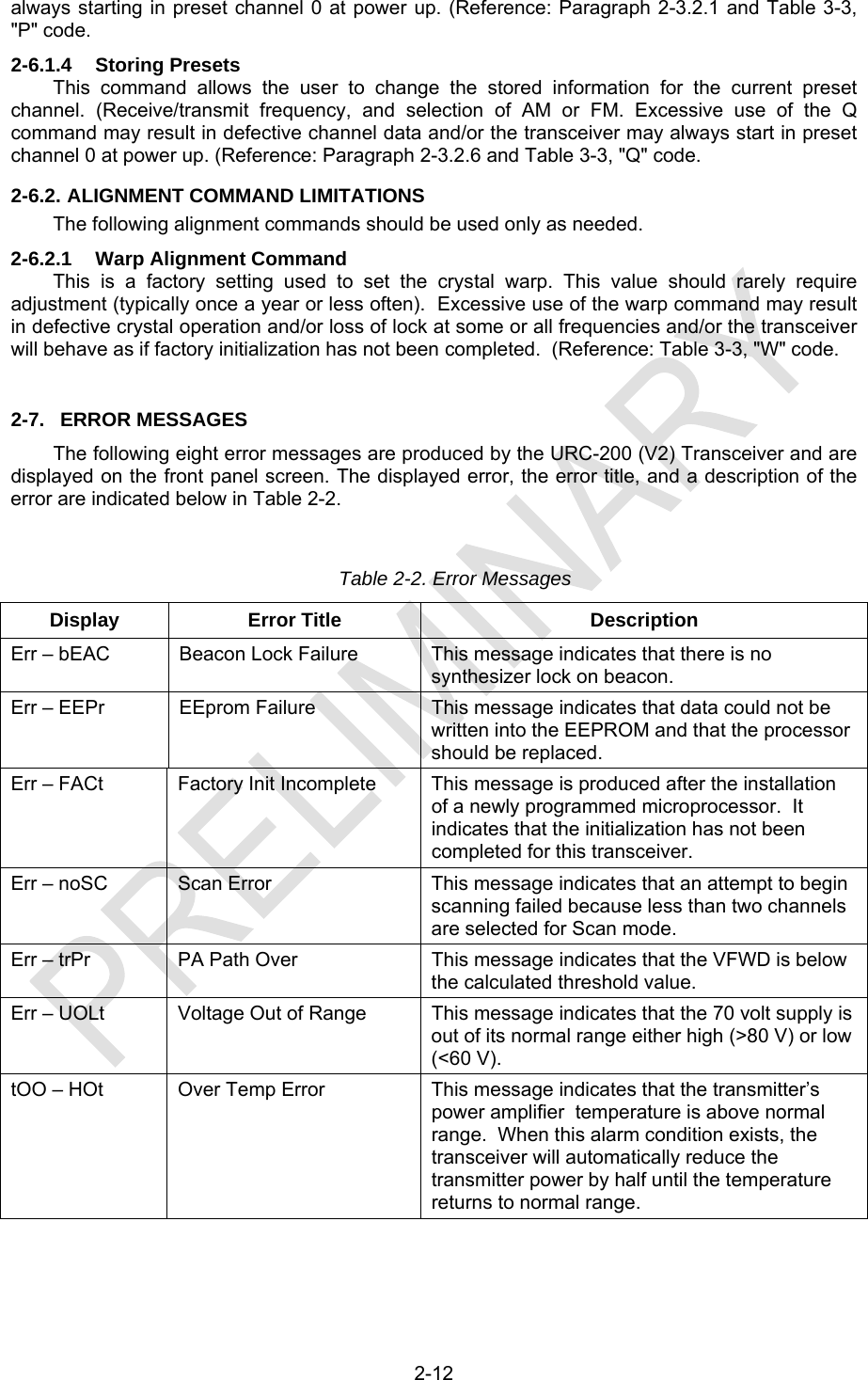
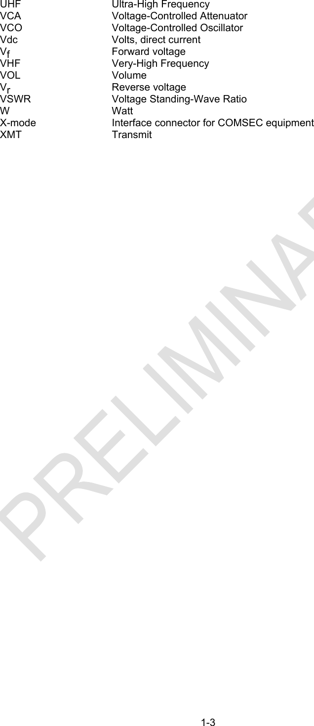
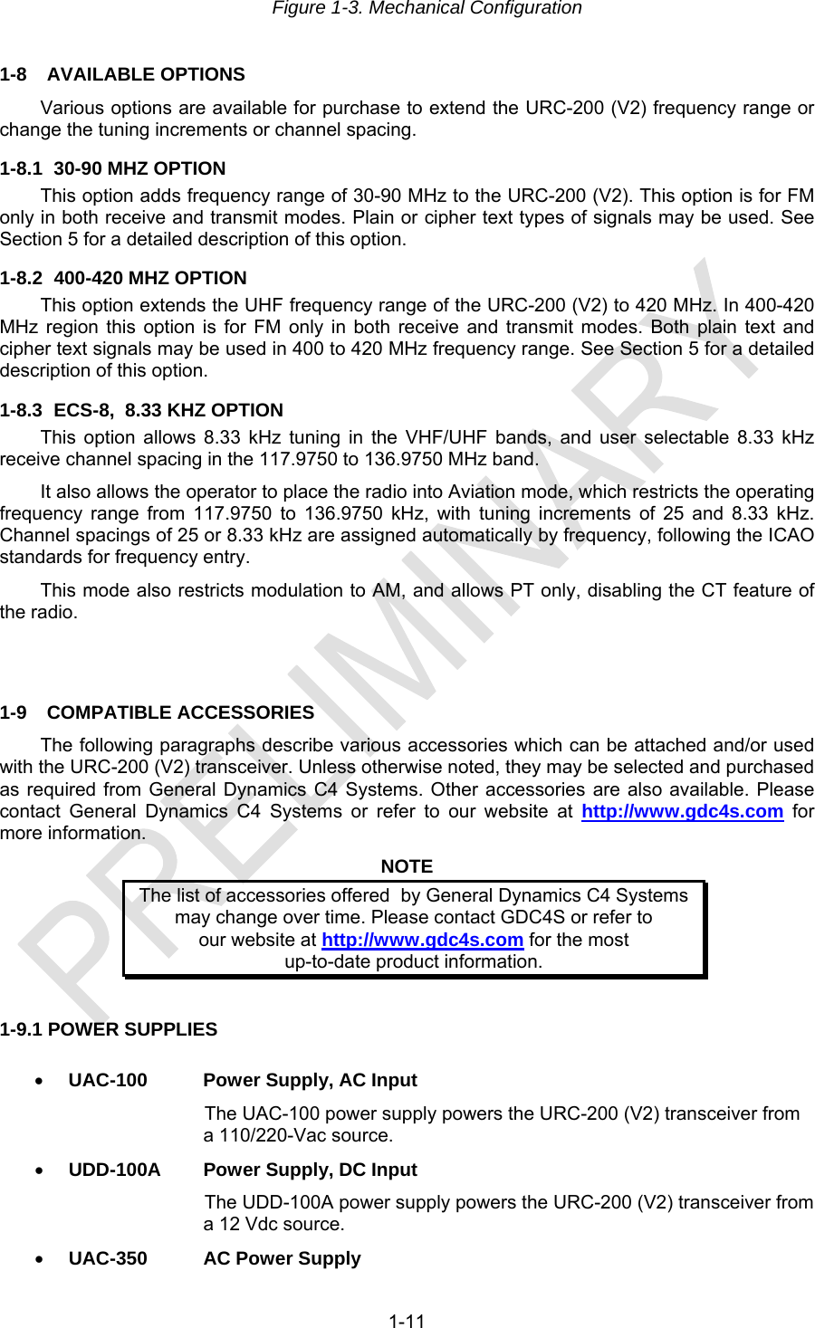
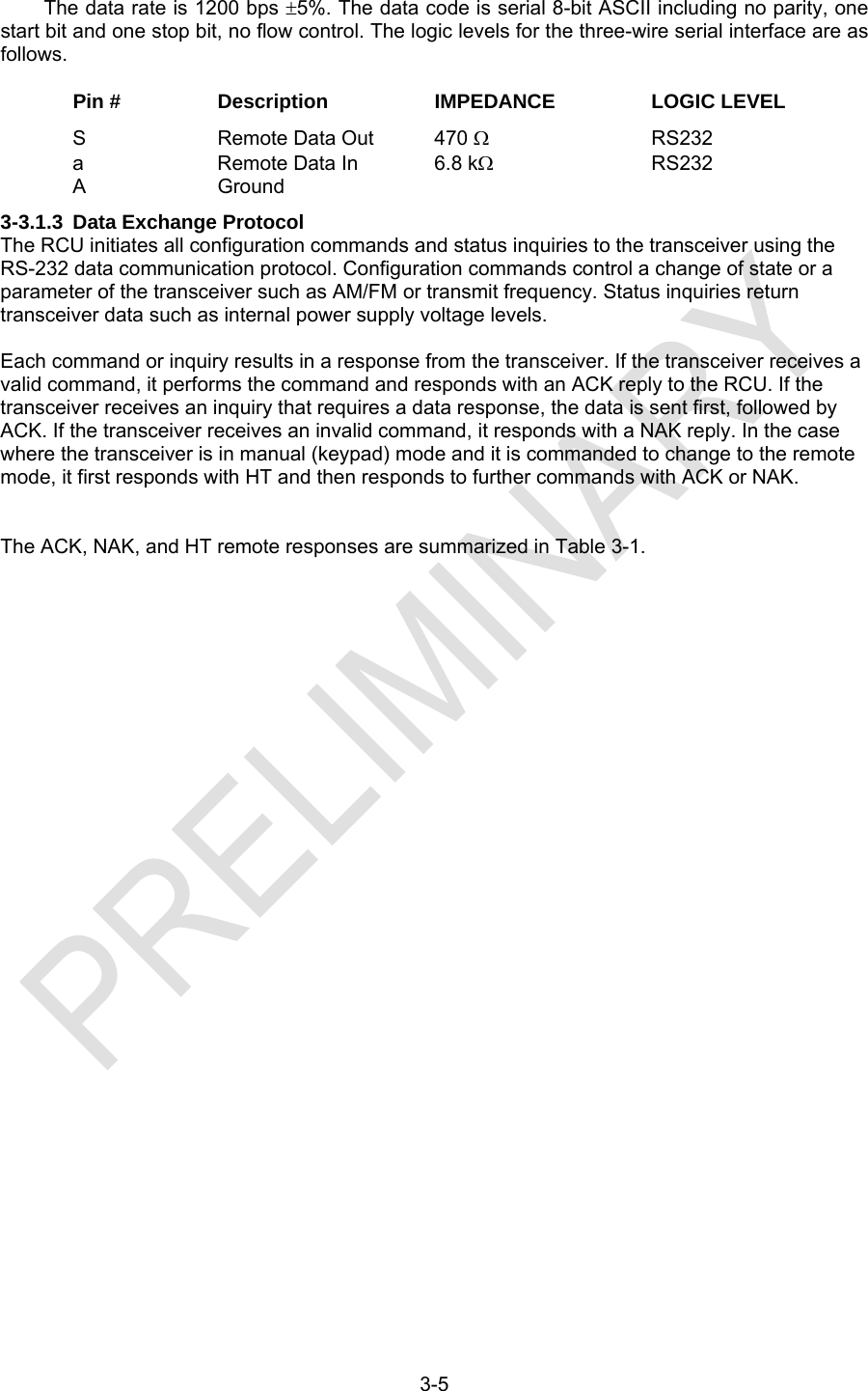
![3-4 3-3. REMOTE OPERATION The Remote Control Unit (RCU) shown in Figure 3-1 can either be a personal computer or it can be a Remote Terminal Unit (a handset, or a control head connected by a cable of up to 250 ft). As shown, the RCU is connected in a master/slave relationship to the transceiver and the RCU always initiates a given command. All commands are sent as a series of ASCII characters over the RS232 connection. RCU RADIO(MASTER) (SLAVE) Figure 3-1. Remote-Control Unit When first powered up, the RCU sends an ID interrogation code to query what type of radio it is connected to (what options have been attached). Given this information, the RCU restricts the type of commands that it can transmit to the transceiver. When the remote command is recognized by the transceiver as a valid command, the transceiver will enter into the slave mode (the RCU is the master with the transceiver as the slave). The transceiver will also lock out all local keyboard inputs (except for the Release Remote Key Sequence, RRKS: [Mode] [R/T]) allowing all commands to come from the RCU. 3-3.1. REMOTE CONTROL INTERCONNECT 3-3.1.1 X-mode Connector The X-mode pins used for remote-control of the transceiver are: Pin # Description S Remote Data Out (ASCII data from the transceiver) a Remote Data In (ASCII data to the transceiver) A Ground 3-3.1.2 Data Rates and Logic Levels If using HyperTerminal, configure as shown.](https://usermanual.wiki/General-Dynamics-C4-Systems/URC-200XCVR-V2/User-Guide-1196302-Page-38.png)
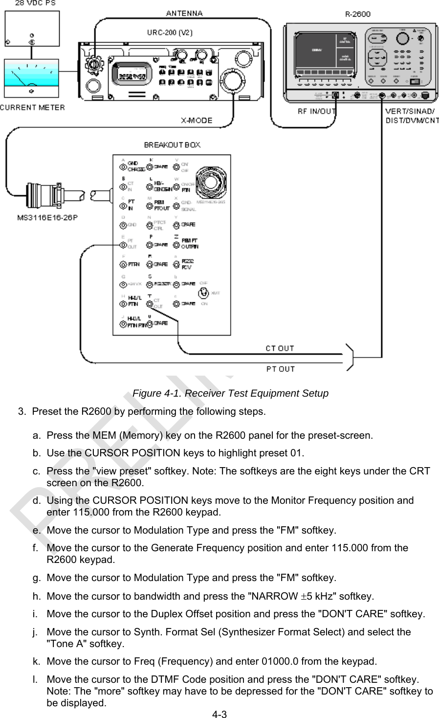

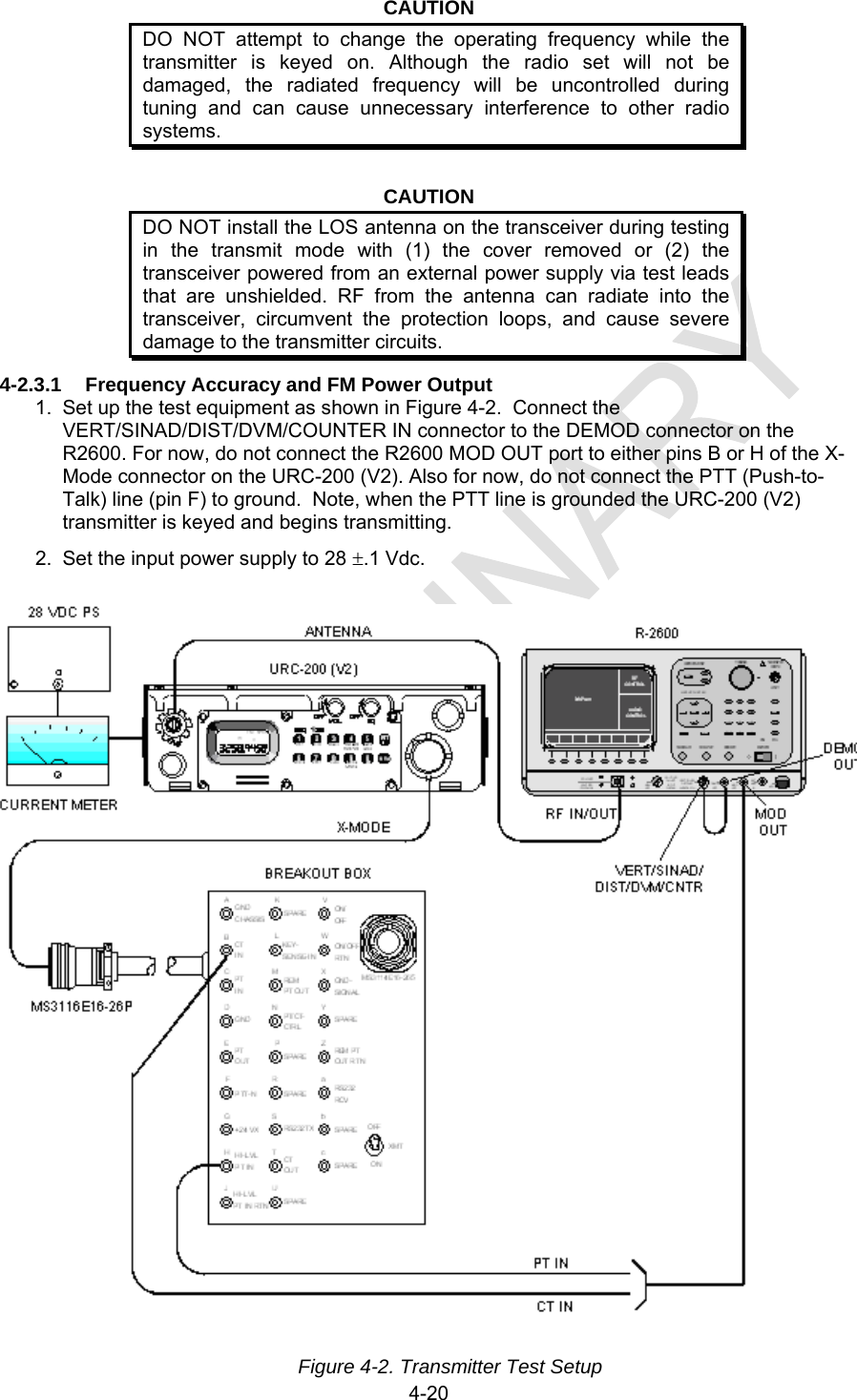
![4-29 NOTE When measuring AM transmitter output power on the R2600 or on any power meter that has a peak detector, which includes virtually all of the portable inline or direct power meters, the carrier power that is read on the wattmeter will need to be converted to average power to verify compliance as indicated above. To convert carrier power to average power use the following formula: PAVG = PC [1 + (m2 / 2)] where: PAVG = Average Power PC = Carrier Power m = modulation as a decimal; i.e., 80% = .8 It should be noted, that in order to obtain the modulation value for the above formula, the next step (c) will need to be completed. c. Read the AM % modulation on the R2600 screen. Verify compliance with Table 1-1 in Section 1 of this manual. d. Depress the DISP key on the R2600 front panel. Move the cursor to the Meter position and press the "EXT DIST" softkey. Note: The "more" softkey may have to be depressed for the "EXT DIST" softkey to be displayed. Read the % of distortion on the R2600 screen. Verify compliance with Table 1-1 in Section 1 of this manual. e. Unkey the URC-200 (V2) and adjust it for HI POWER. Depress the DISP key on the R2600 front panel. Move the cursor to the Meter position and press the "RF DISPLAY" softkey. Note: The "more" softkey may have to be depressed for the "RF DISPLAY" softkey to be displayed. Rekey the URC-200 (V2) and verify compliance with Table 1-1 in Section 1 of this manual. NOTE When measuring AM transmitter output power on the R2600 or on any power meter that has a peak detector, which includes virtually all of the portable inline or direct power meters, the carrier power that is read on the wattmeter will need to be converted to average power to verify compliance as indicated above. To convert carrier power to average power use the following formula: PAVG = PC [1 + (m2 / 2)] where: PAVG = Average Power PC = Carrier Power m = modulation as a decimal; i.e., 80% = .8 It should be noted, that the modulation has to be measured in order to obtain the modulation value for the above formula. f. On both the URC-200 (V2) and the R2600 repeat steps A through E for preselect channels 2 through 9 and channel 0 on the URC-200 (V2) with the R2600 set on preset channel 10. 4-2.3.5 AM CT % Modulation and CT Distortion 1. Set up the test equipment as shown in Figure 4-2. Connect the VERT/SINAD/DIST/DVM/COUNTER IN connector to the DEMOD connector on the R2600. On the R2600 connect the MOD OUT connector to pin B of the X-MODE connector on the URC-200 (V2). Do not connect the PTT (Push-to-Talk) line (pin F) to ground. Note: When the PTT line is grounded the URC-200 (V2)'s transmitter will key itself ON. 2. Set the input power supply to 28 .1 Vdc. 3. Preset the R2600 by performing the following steps.](https://usermanual.wiki/General-Dynamics-C4-Systems/URC-200XCVR-V2/User-Guide-1196302-Page-86.png)
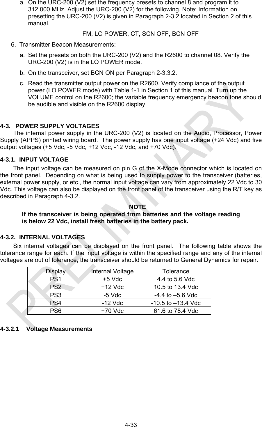
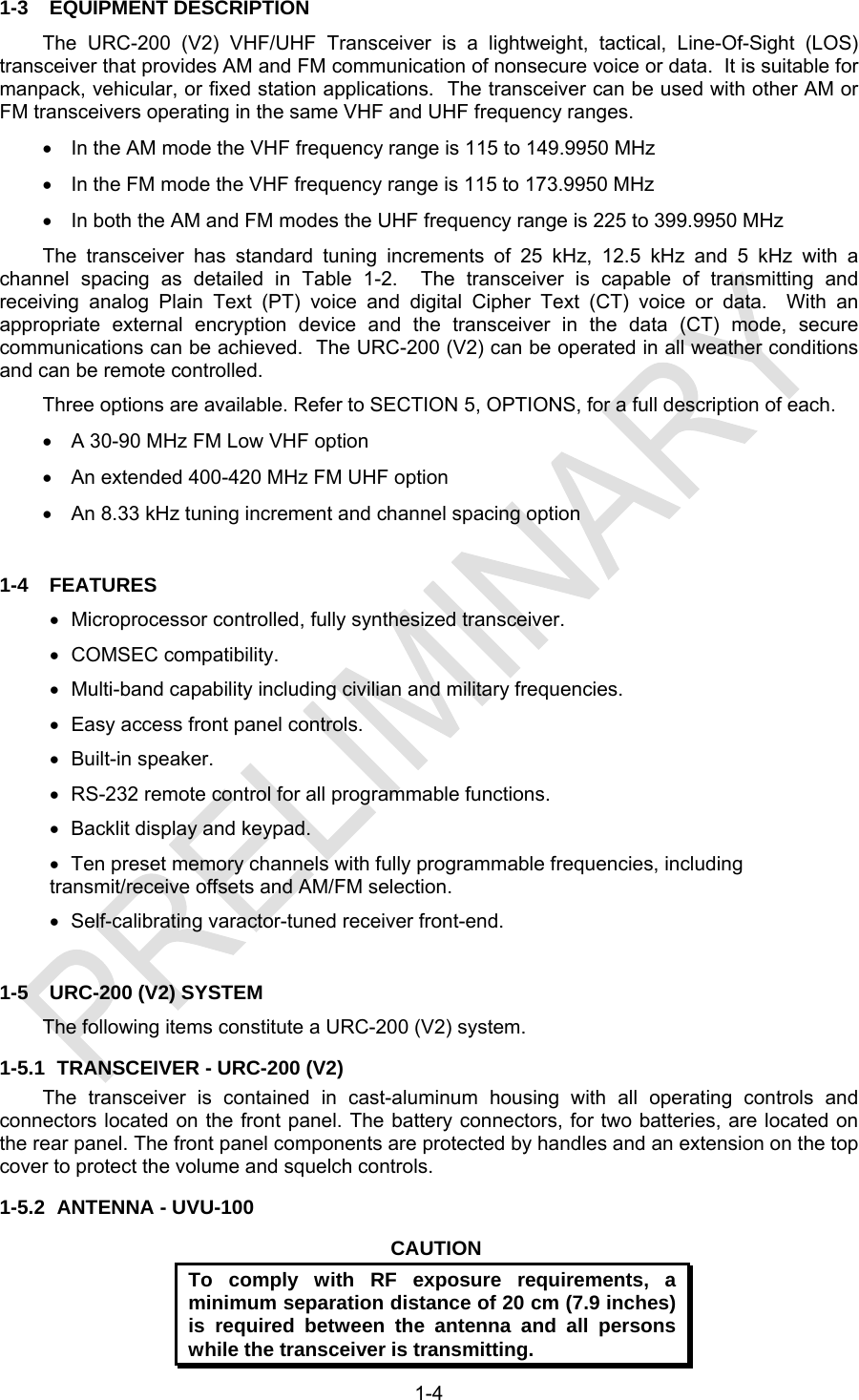
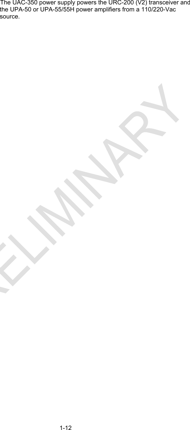
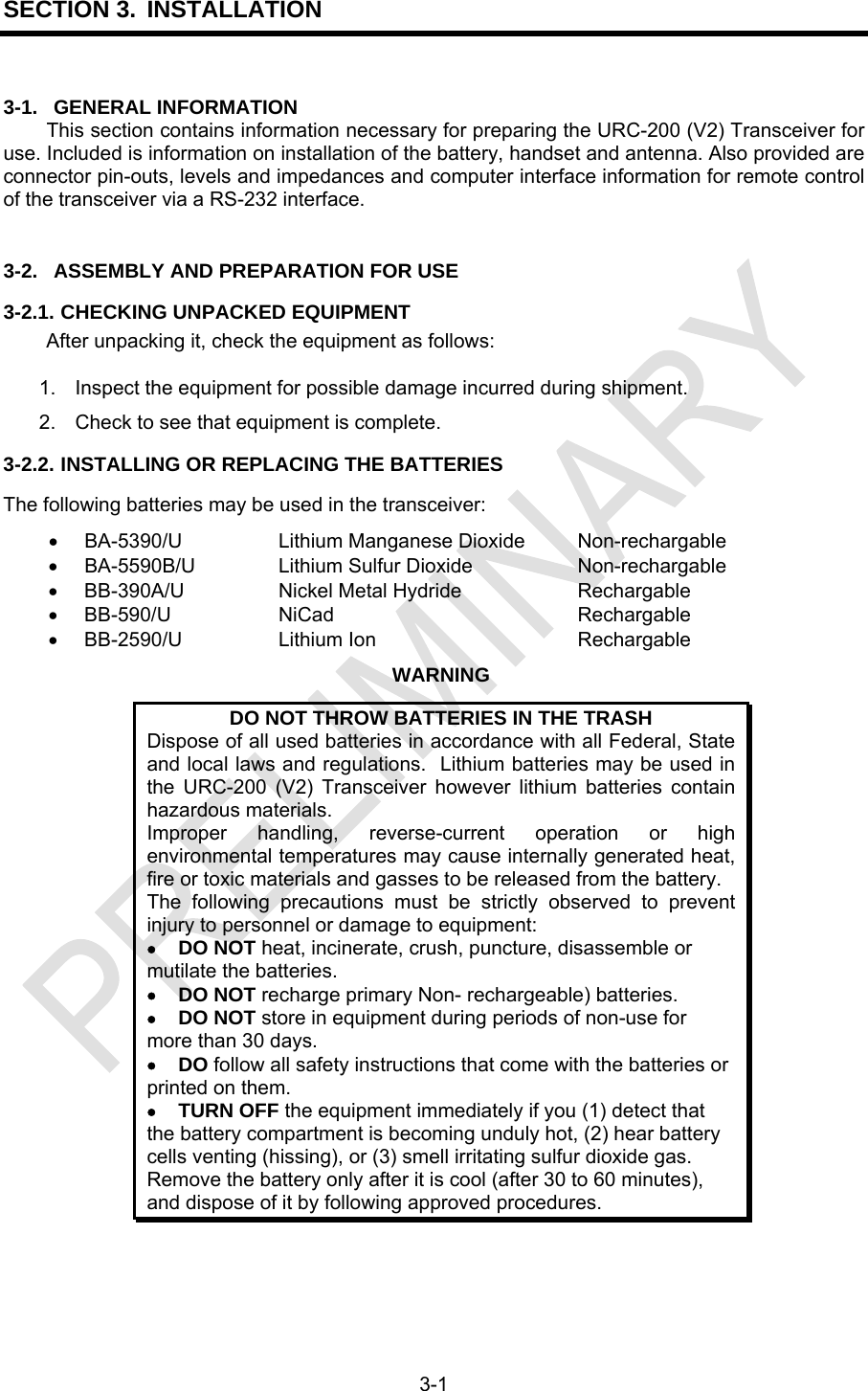
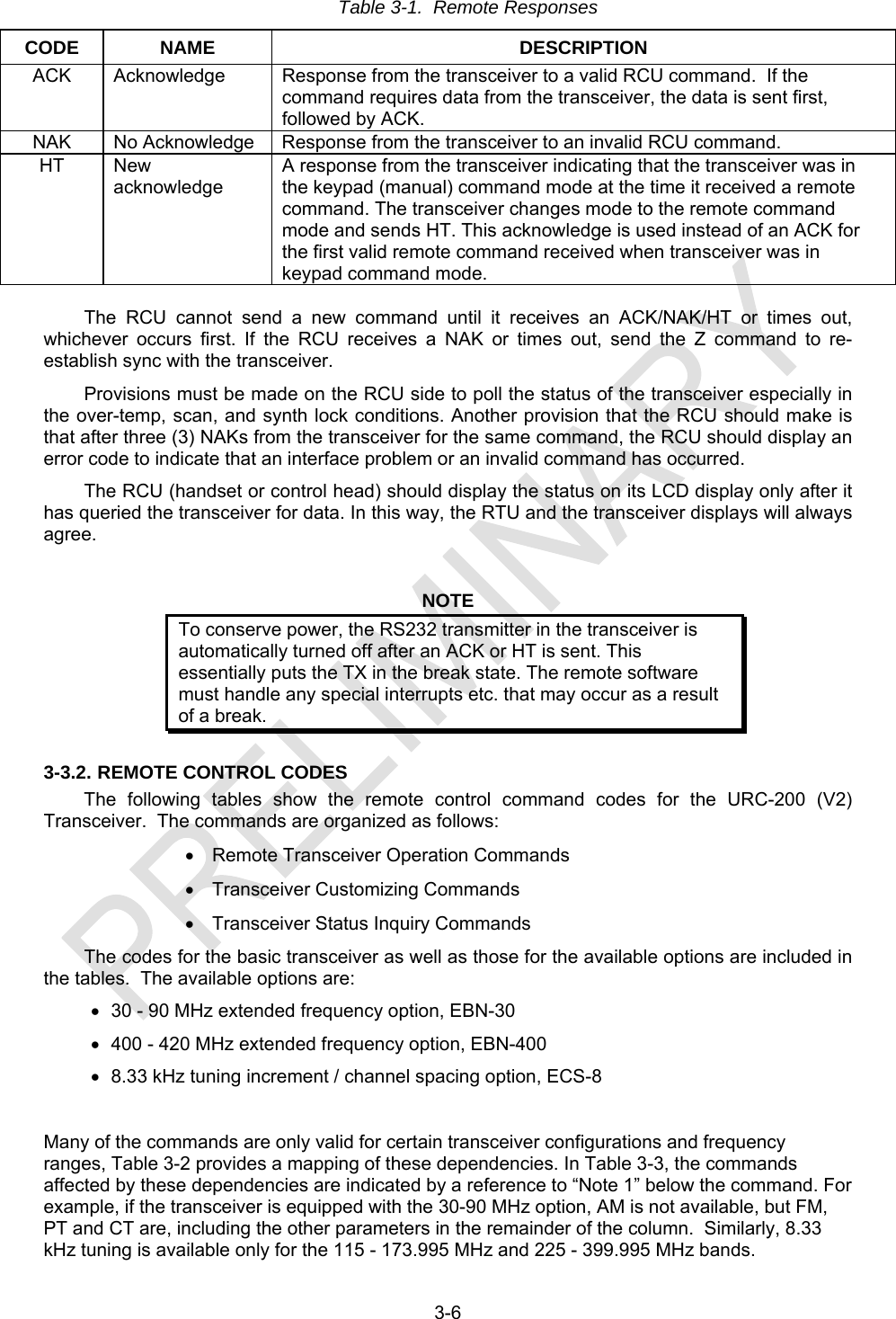
![4-34 With the transceiver set-up in the meter-mode per Paragraph 2-3.1.5., pressing the [R/T] key will display the voltages of the internal power supplies and of the batteries. The first time [R/T] is pressed the voltage of the +5Vdc supply - PS1 is displayed. Each consecutive press of [R/T] brings up the next supply; PS2: +12Vdc, PS3: -5Vdc, PS4: -12Vdc, PS5: +24Vdc (external power batteries), PS6: +70Vdc and AGC. NOTE The AGC level displayed is not a voltage. The AGC is expressed as a digital value from 000 to 255. Figure 4-4. Breakout Box Schematic Note: When performing the Receiver Tests in accordance with Paragraph 4-2.2 and Figure 4-1: ● For the PT OUT on pin E of the Breakout Box, Pin D is the ground return.](https://usermanual.wiki/General-Dynamics-C4-Systems/URC-200XCVR-V2/User-Guide-1196302-Page-91.png)
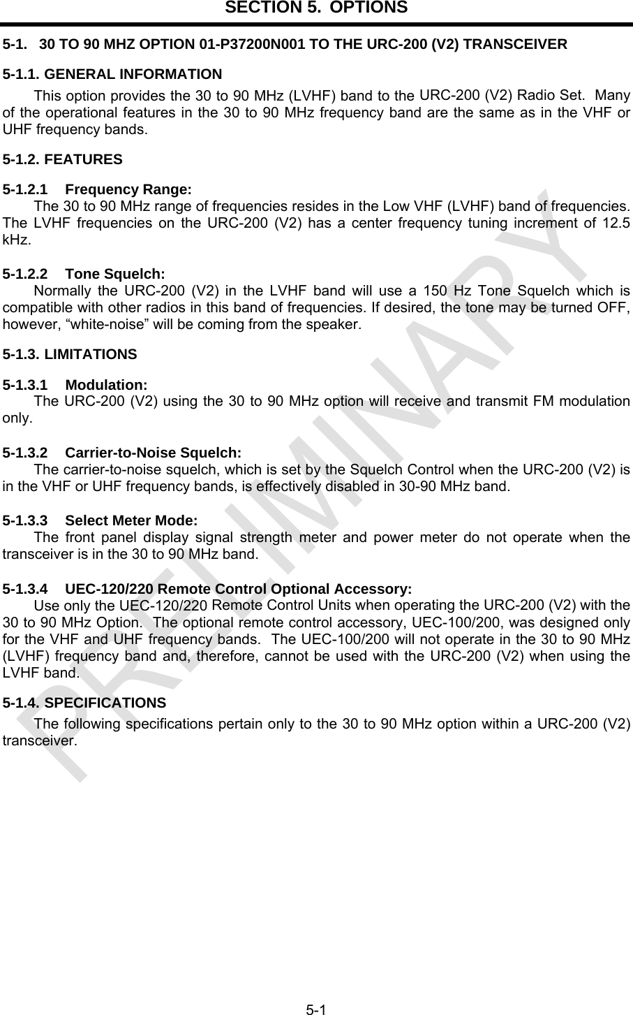
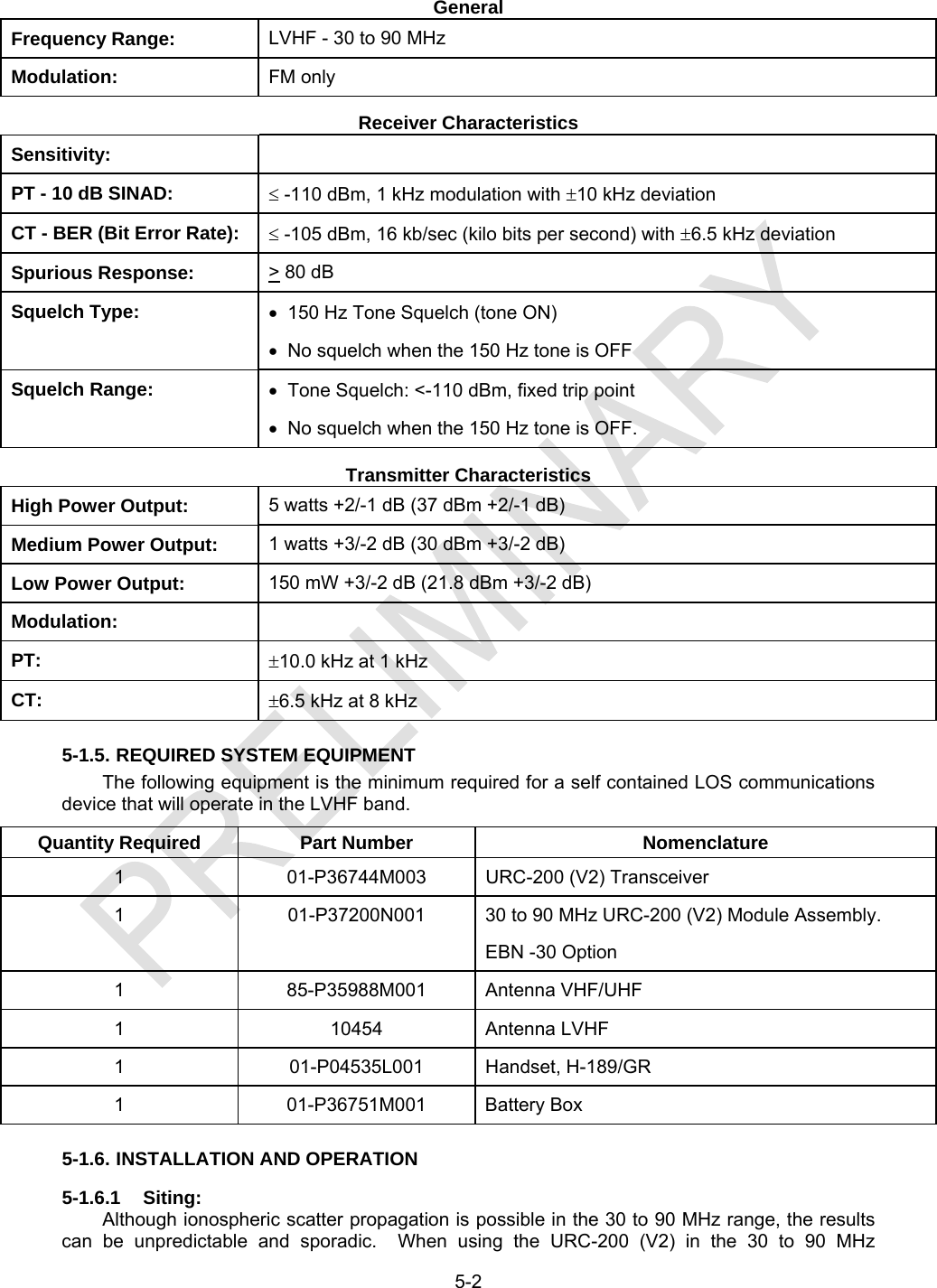
![5-3 frequency band (LVHF) it is recommended that the same line-of-sight (LOS) siting considerations be applied as when operating in the VHF or UHF frequency bands. 5-1.6.2 Antenna Installation: Connect the LVHF antenna to the type “N” connector on the front panel. Route the gooseneck portion of the antenna base so the antenna is oriented vertically. Satisfactory performance is achieved with the LVHF antenna and the VHF/UHF antenna mounted on the URC-200 (V2) at the same time. However, the unused antenna should be removed for optimum antenna performance. 5-1.6.3 Selecting LVHF Frequencies: Press the [FREQ] key (keypad [1]) to select the frequency entry mode. To select a frequency in the LVHF band, a zero (0) must be pressed before entering the desired frequency. For example, to enter 35.6 MHz, press [0] [3] [5] [6] [0] [0]. 5-1.6.4 Squelch: The 30 to 90 MHz band employs a 150 Hz Tone Squelch. To activate the Tone Squelch, press the [TONE] key (keypad [2]). A lower case “t” will appear at the 100 MHz position on the display when the Tone Squelch is active, or turned ON. When using the 150 Hz Tone Squelch, the Squelch Control will not effect the tone squelch threshold. It should be noted that the only signals that will break the receiver’s squelch, when the Tone Squelch is ON, are those that are on-channel and are being modulated with a 150 Hz tone that has a sufficient deviation level to break the receiver’s tone squelch threshold. If desired, the 150 Hz Tone Squelch may be deactivated, or turned OFF. The lower case “t” will disappear from the 100 MHz position on the display when the Tone Squelch is turned OFF. With the tone turned OFF there is no squelching of the white-noise on the URC-200 (V2).](https://usermanual.wiki/General-Dynamics-C4-Systems/URC-200XCVR-V2/User-Guide-1196302-Page-95.png)
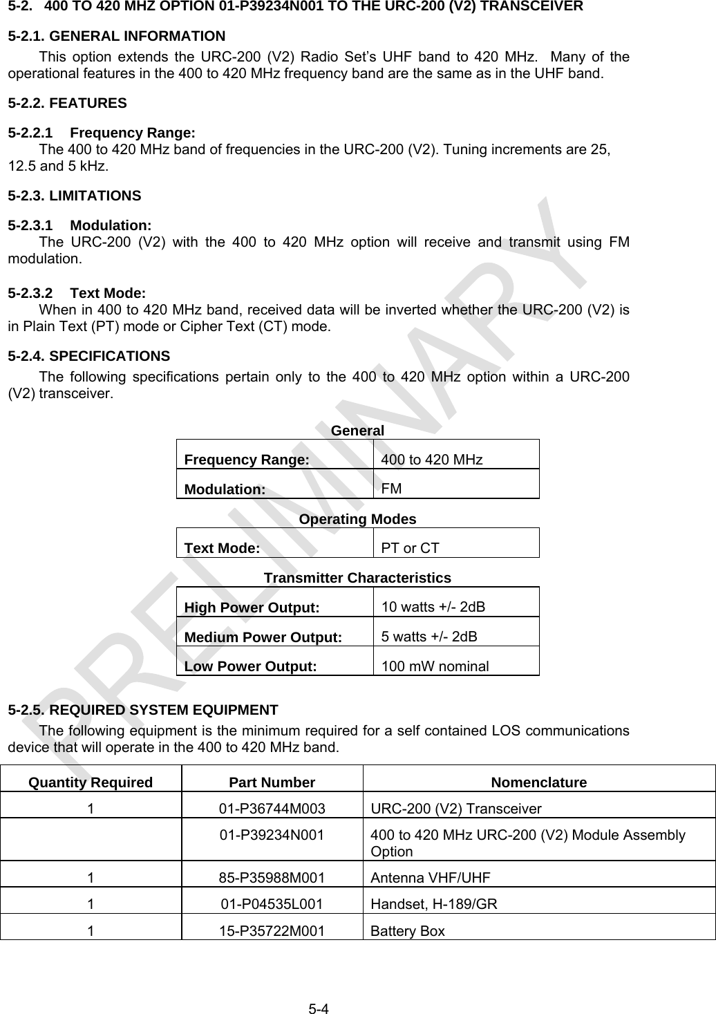
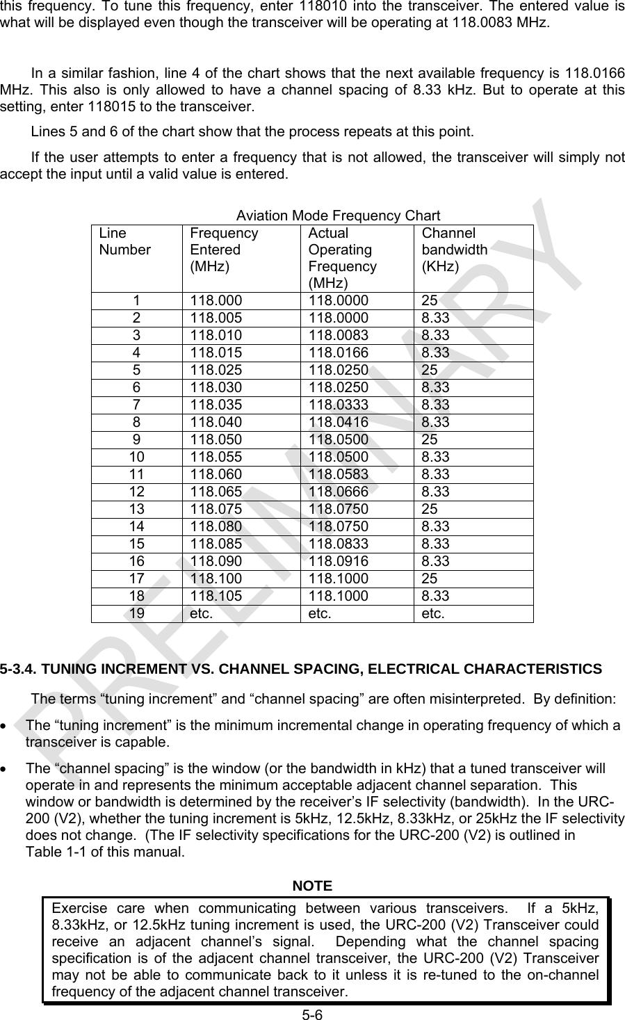
![5-5 5-2.6. INSTALLATION AND OPERATION 5-2.6.1 Selecting 400 to 420 MHz Frequencies: Press the [FREQ] key (keypad [1]) to select frequency entry mode. To select a frequency, enter the desired frequency. 5-3. ECS- 8 OPTION - PART NUMBER 01-P42311K001 5-3.1. GENERAL INFORMATION This option allows 8.33 kHz tuning in the VHF/UHF bands, and user selectable 8.33 kHz receive channel spacing in the 117.9750 to 136.9750 MHz band. It also allows the operator to place the radio into Aviation mode, which restricts the operating frequency range from 117.9750 to 136.9750 kHz, with tuning increments of 25 and 8.33 kHz. Channel spacings of 25 or 8.33 kHz are assigned automatically by frequency, following the ICAO standards for frequency entry. This mode also restricts modulation to AM, and allows PT only, disabling the CT feature of the radio. 5-3.2. ENABLING AVIATION MODE To place the transceiver in the Aviation Mode, start with the transceiver powered off and then press and hold the 4 [AV] keypad while turning on the power. The unit will remain in the aviation mode through subsequent power cycles until it is returned to the normal operating mode. The transceiver will set all the channel data for each channel to a default value (118 MHz, PT, AM, 25 kHz bandwidth, low power). To return to the normal operating mode, start with the transceiver powered off and press and hold the 6 [MODE] key while turning on power. The transceiver will reset all the channel data for each channel to the default values (225 MHz, PT, AM, 25 kHz bandwidth, low power). . 5-3.3. TUNING AND CHANNEL SPACING IN AVIATION MODE When in the Aviation Mode, the manner in which the frequency is entered and displayed determines the actual operating frequency and the channel spacing. The ICAO standard mandates that specific channel spacings (either 25 or 8.33 kHz) shall be assigned to specific frequency entries. This also means the frequency that is entered and displayed may be different from the actual frequency the transceiver is tuned to. The Aviation Mode Frequency Chart below shows an example of how to enter frequencies to select the desired operating frequency and channel spacing. 118 MHz is used in the table as an example; however any frequency from 117.9750 to 136.9750 kHz may be selected. For example, if the desired actual operating frequency is 118.000 MHz with a channel spacing of 25 kHz, enter 118000 using the keypad or remote command. The result will be what is shown in line 1 of the chart. If, however, the desired frequency is still 118.000 MHz but this time with a channel spacing of 8.33kHz, enter 118005 and the result will be as shown in line 2 of the chart. Note that the transceiver will display 118005 even though it is tuned to 118.000 MHz. In some cases, only 8.33 kHz channel spacing is allowed. Examine lines 3 and 4 of the chart. Because tuning increments of 8.33 kHz are allowed, the next possible operating frequency after 118.000 MHz is 118.0083 MHz. In this case only 8.33 kHz channel spacing is available for](https://usermanual.wiki/General-Dynamics-C4-Systems/URC-200XCVR-V2/User-Guide-1196302-Page-97.png)