General Dynamics Itronix IX-BR-51 IX-BTBR51 User Manual 1
General Dynamics Itronix Corporation IX-BTBR51 1
UserManual.wiki
>
General Dynamics Itronix
>
IX-BR-51 User Manual
>
User Manual 1
Contents
1.
Radio Specific Safety Information
2.
User Manual 2
3.
User Manual 1
User Manual 1
Navigation menu
Upload a User Manual
Namespaces
Wiki Guide
HTML
PDF
Info
Views
User Manual
Discussion / Help
Navigation
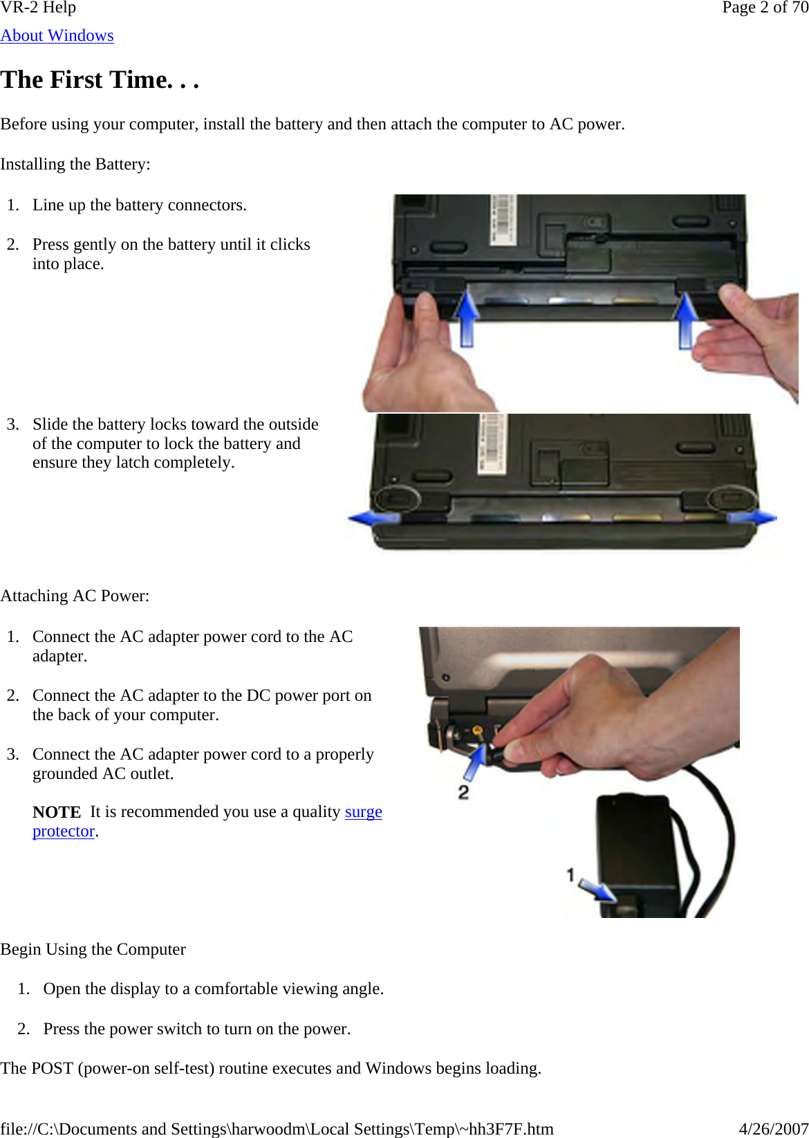
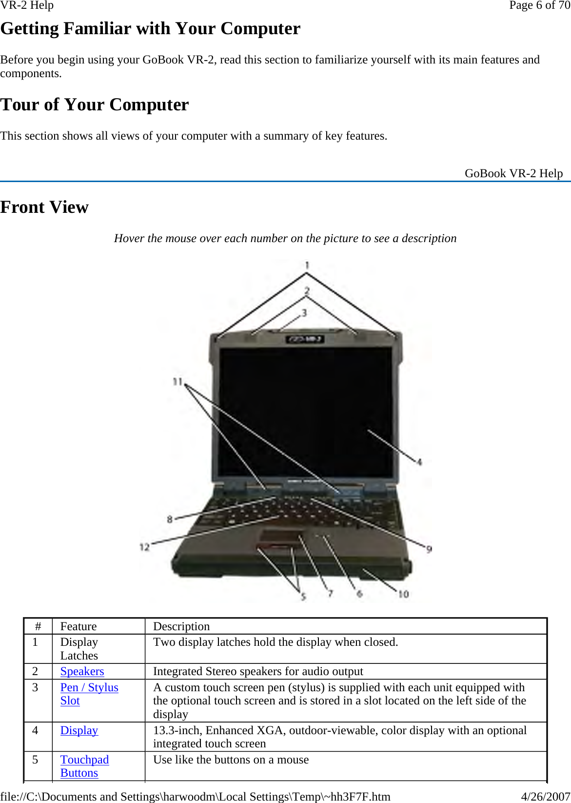
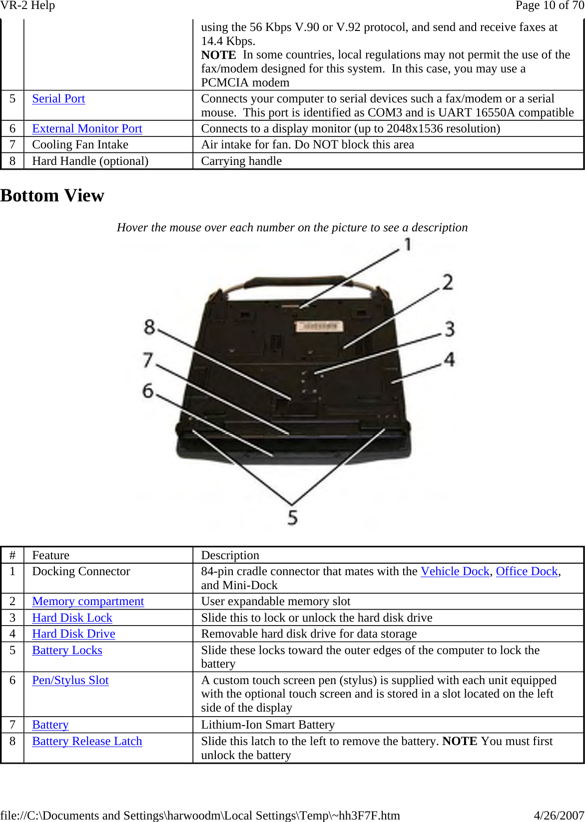
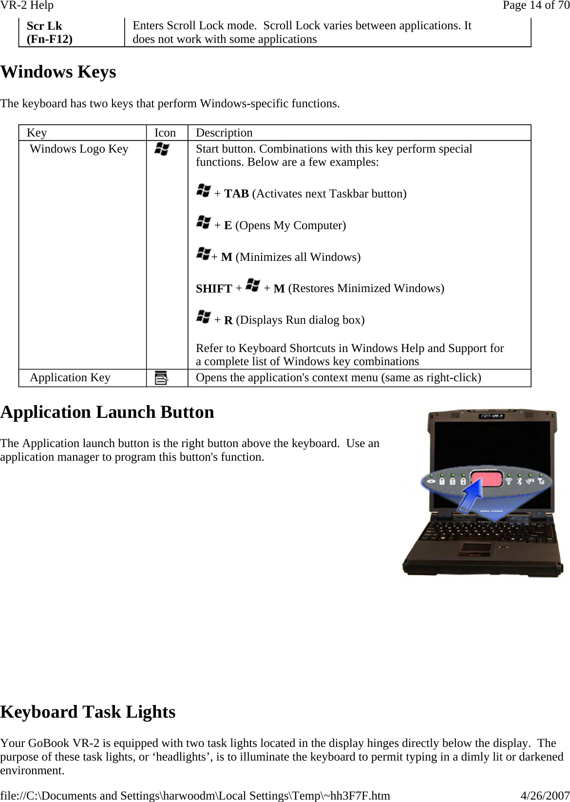
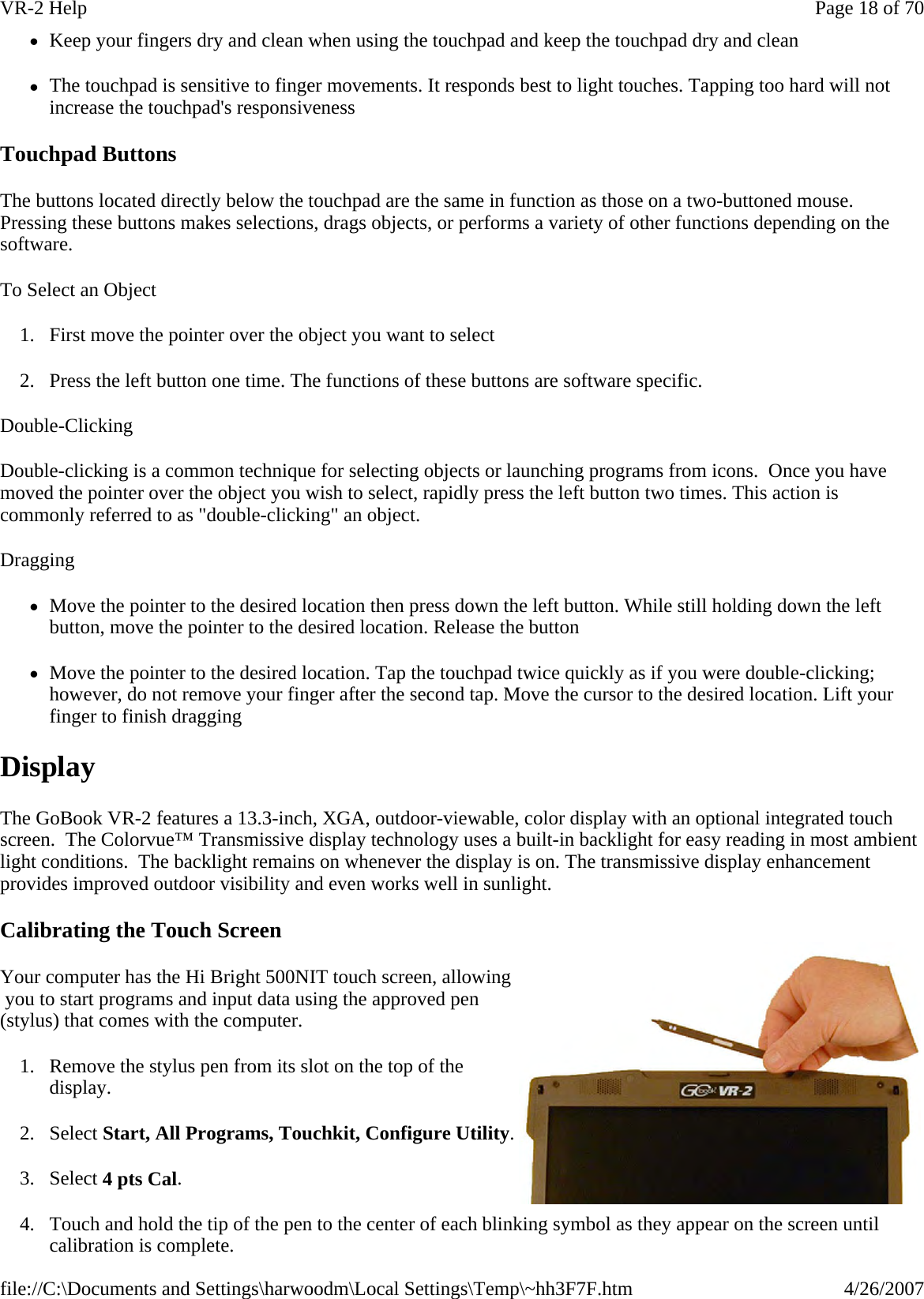
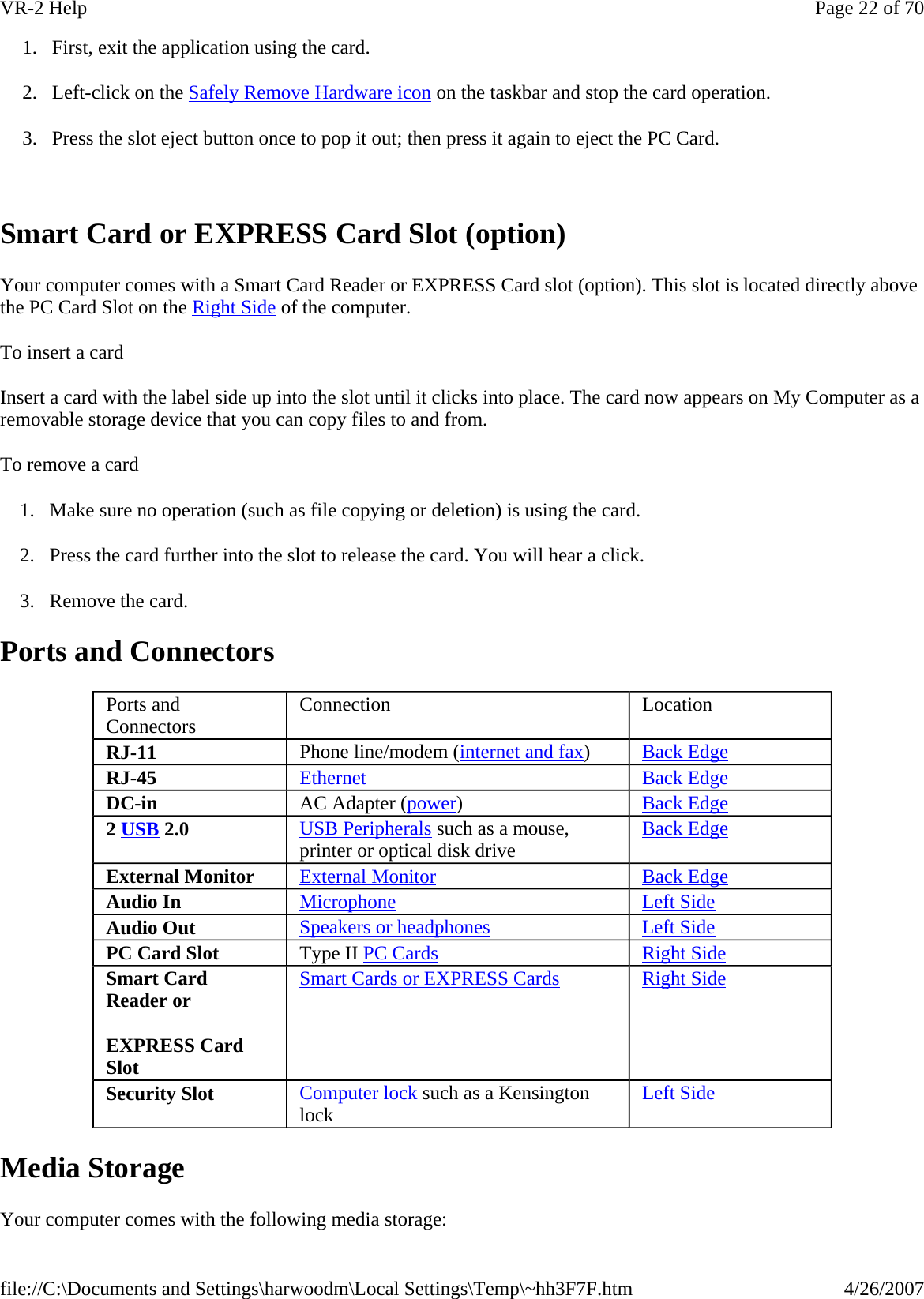
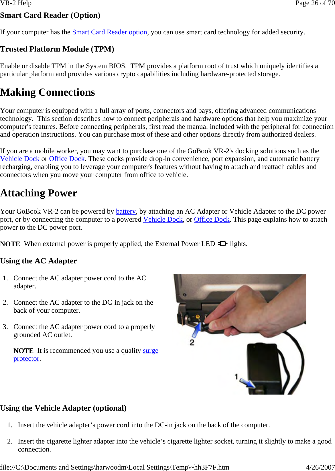
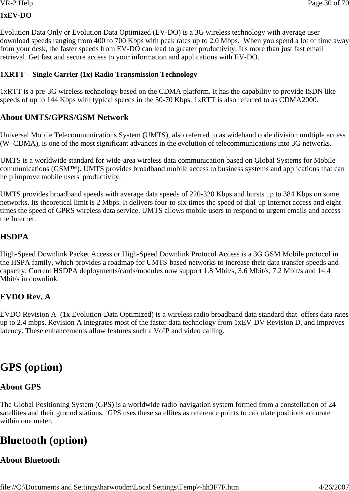
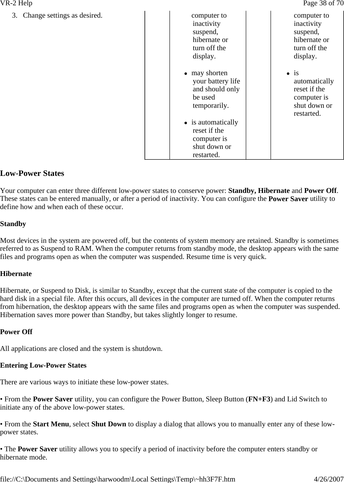
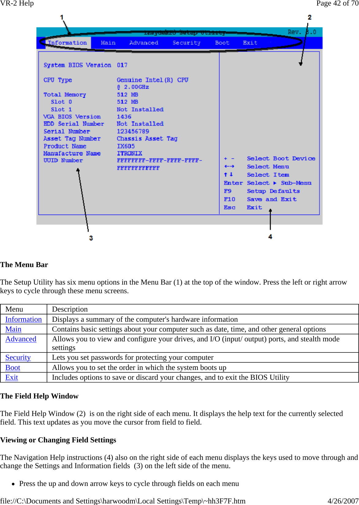
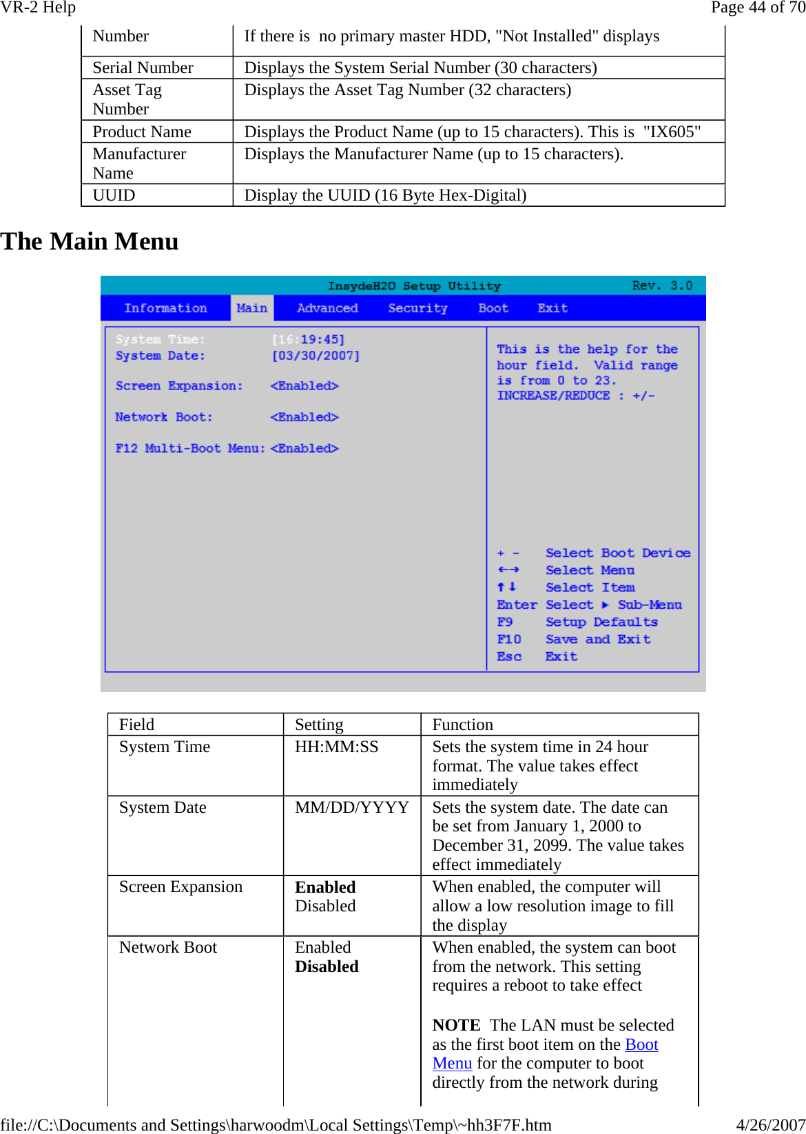
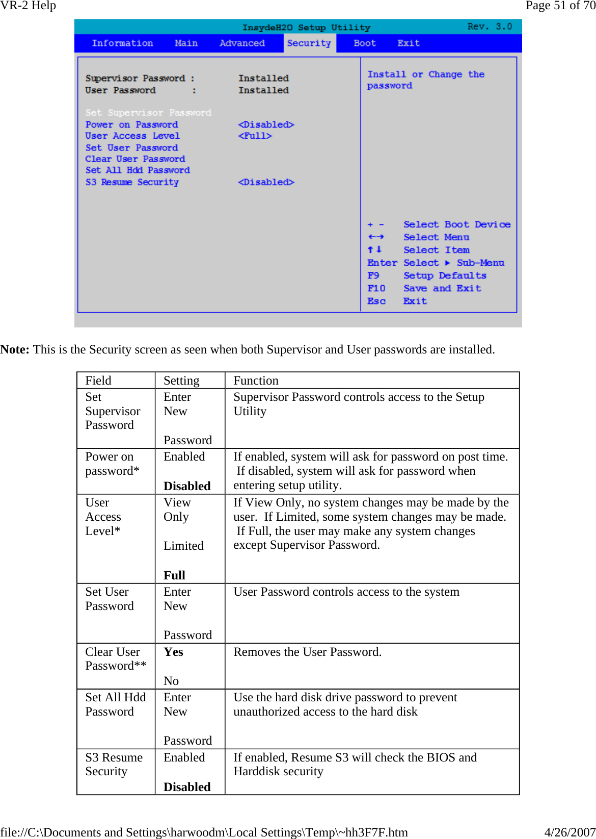
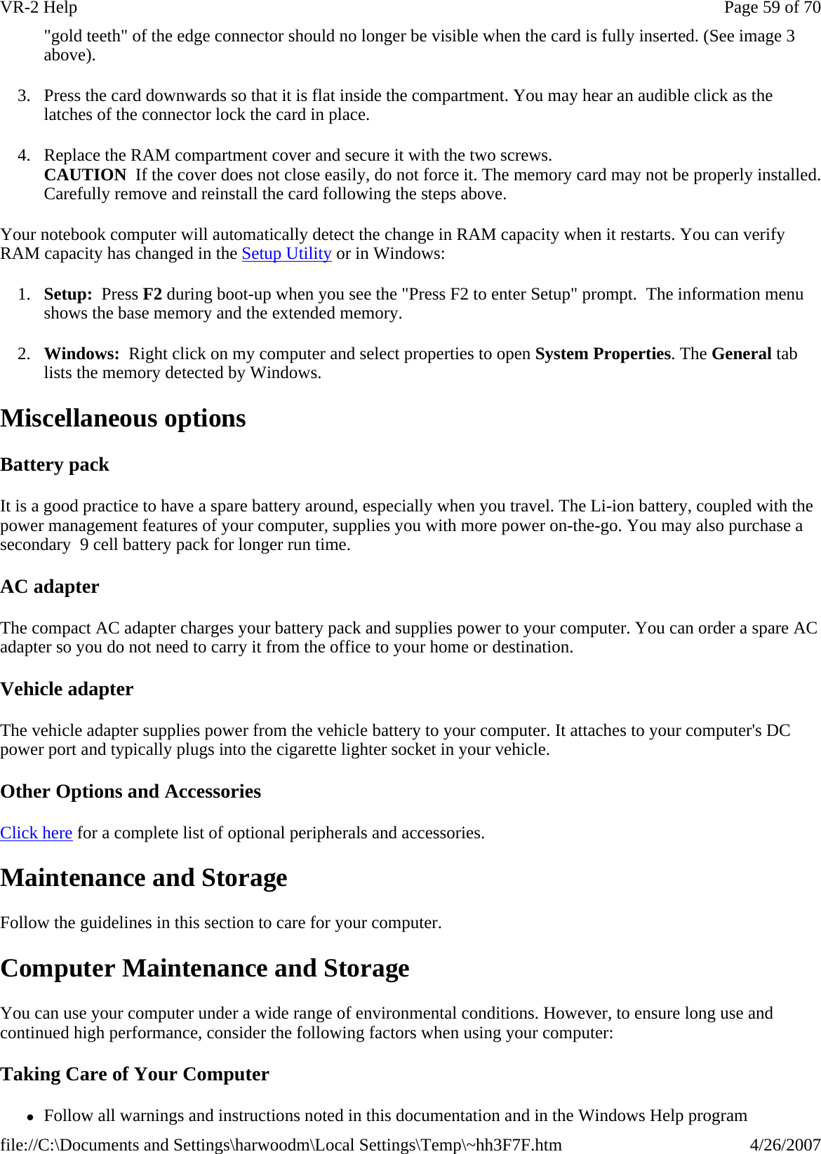
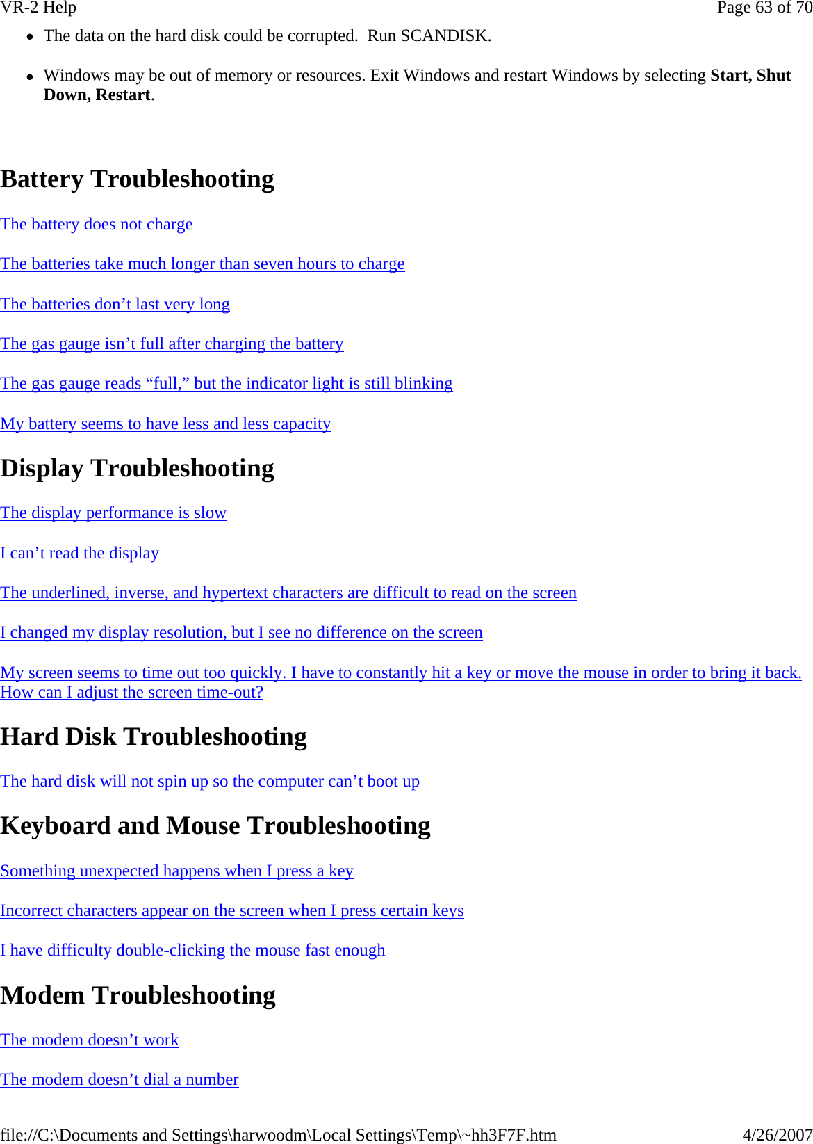
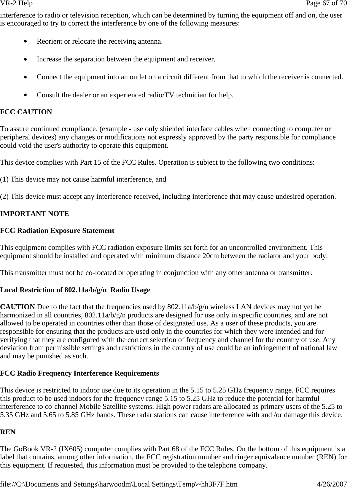
![The Security Menu You can set, change or remove passwords in the Security menu.IDE Controller Enabled Disabled If enabled, both the PATA and SATA IDE Controllers are enabled. If disabled, both the PATA and SATA IDE controllers are disabled. HDC Configure as PATA Only SATA Only IDE Combined IDE Non-Combined AHCI Sets the Harddisk Controller Configuration Type. SATA Port 0 Hotplug Enabled Disabled If enabled, the SATA Port 0 Hotplug is enabled. SATA Port 1 Hotplug Enabled Disabled If enabled, the SATA Port 1 Hotplug is enabled. SATA Port 1 ILS Enabled Disabled If enabled, the SATA Port 1 InterLock Switch is enabled. SATA Port 2 Hotplug Enabled Disabled If enabled, the SATA Port 2 Hotplug is enabled. Primary IDE Cable Type Auto 40 Pins 80 Pins Determines the type of IDE Cable used. Channel 1 Master Not Installed If a drive is installed, its manufacturer, drive type, and model are displayed. Pressing [Enter] displays additional drive and setting information: Type : <Auto/User Defined> If USER Defined is enabled, the following settings can be changed: 32Bit I/O <Enabled/Disabled> Block Mode: <Enabled/Disabled> Transfer Mode: <Enabled/Disabled> Security Mode: Channel 1 Slave (Drive Model) Channel 2 Master Not Installed Channel 2 Slave Not Installed Channel 3 Master (Drive Model) Channel 3 Slave Not Installed Channel 4 Master Not Installed Channel 4 Slave Not Installed Page 50 of 70VR-2 Help4/26/2007file://C:\Documents and Settings\harwoodm\Local Settings\Temp\~hh3F7F.htm](https://usermanual.wiki/General-Dynamics-Itronix/IX-BR-51.User-Manual-1/User-Guide-891512-Page-50.png)
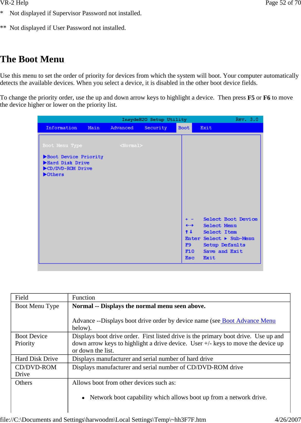
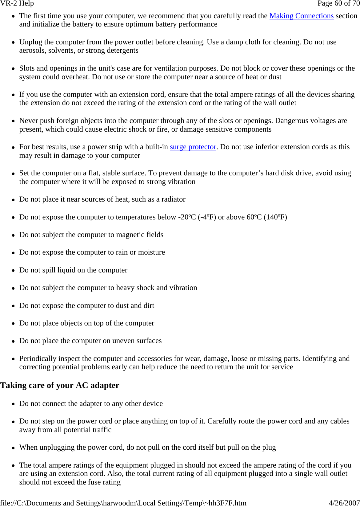
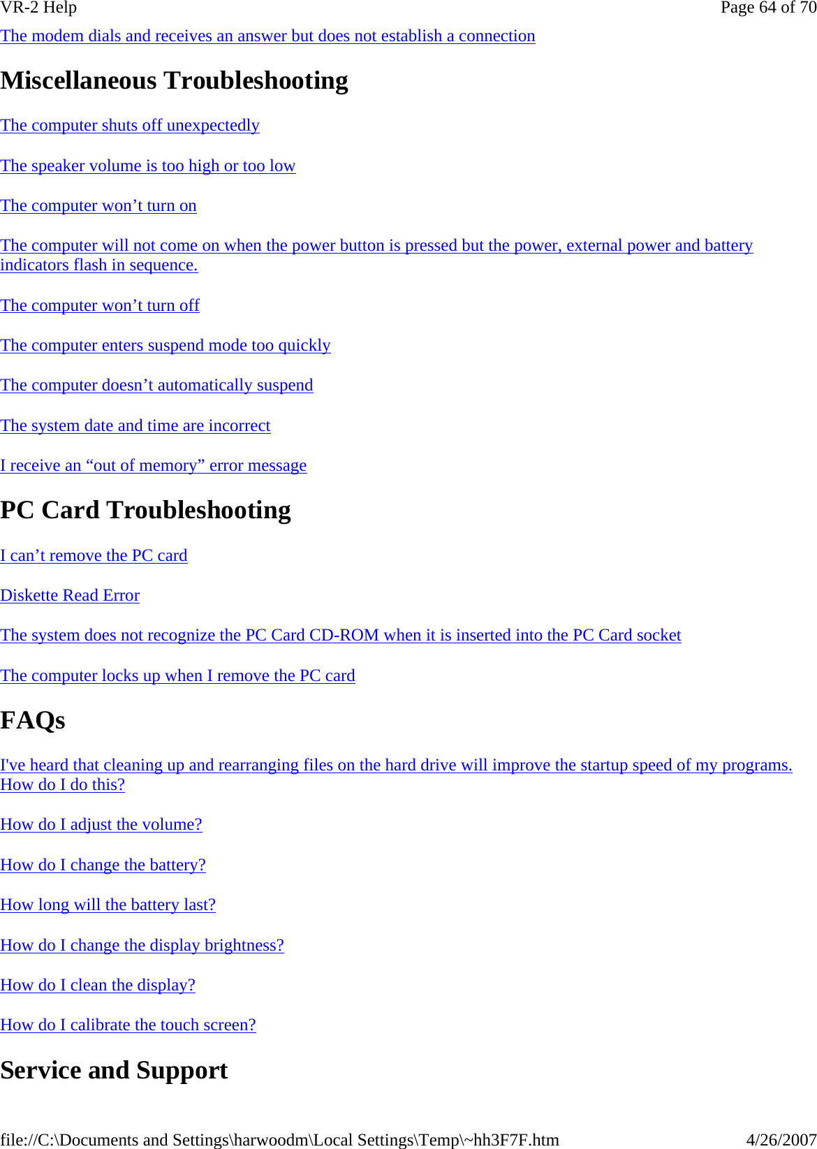
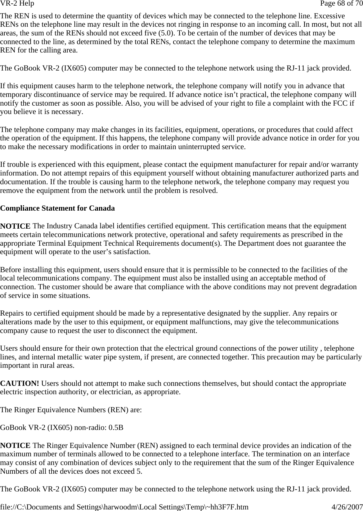
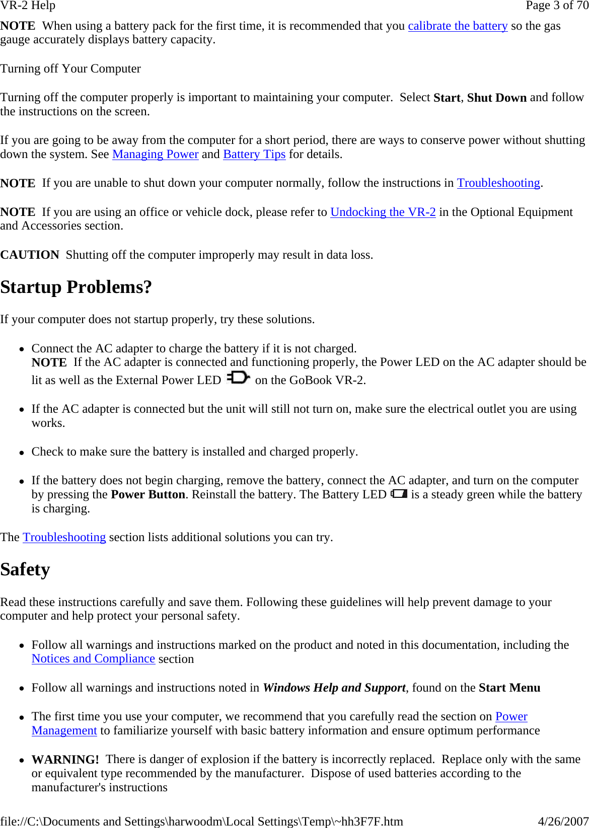
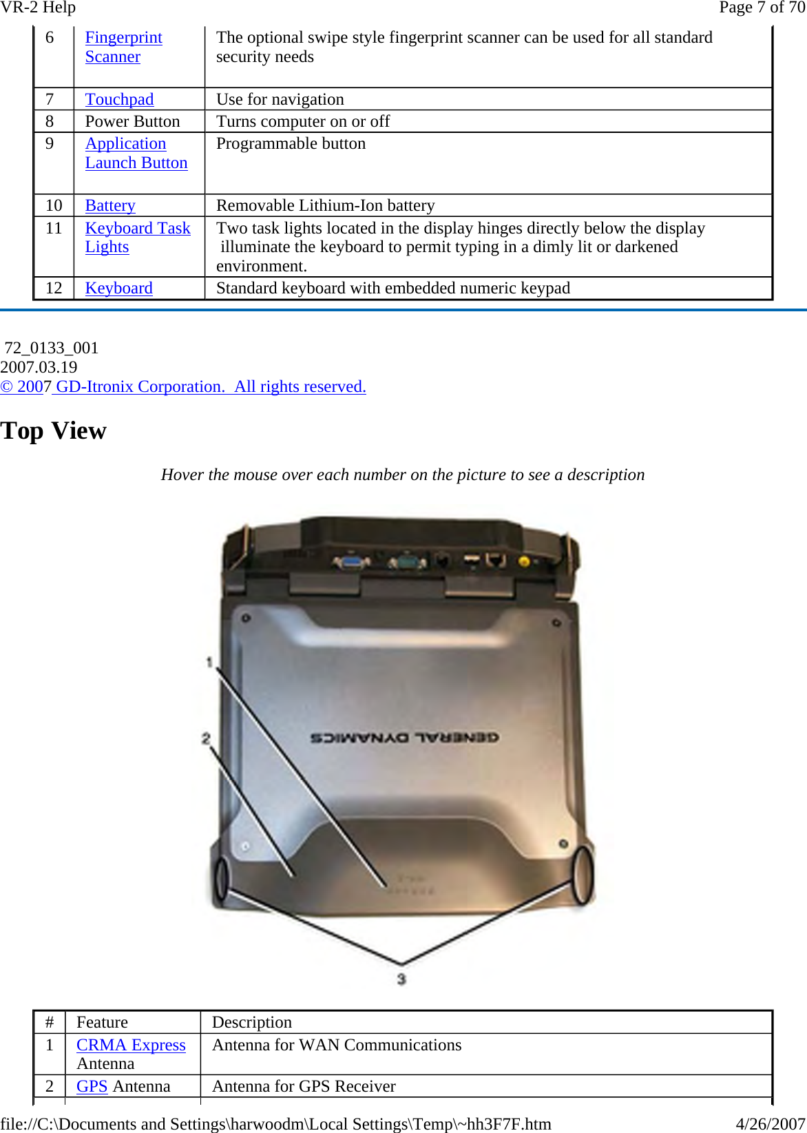
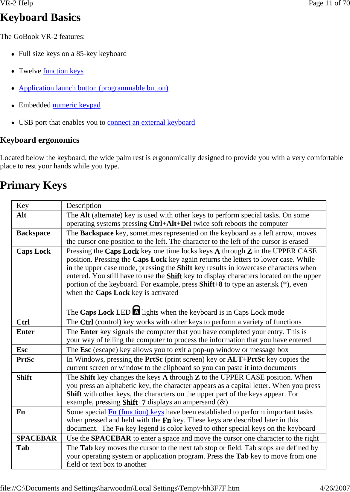
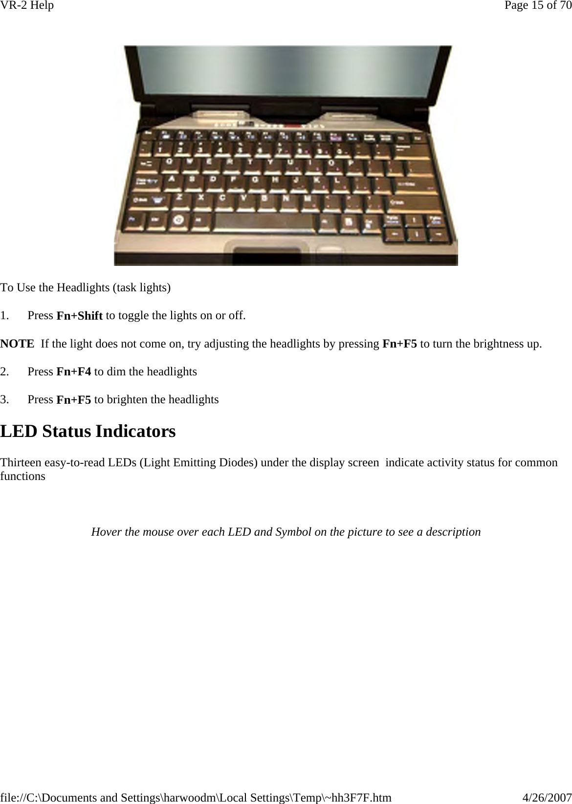
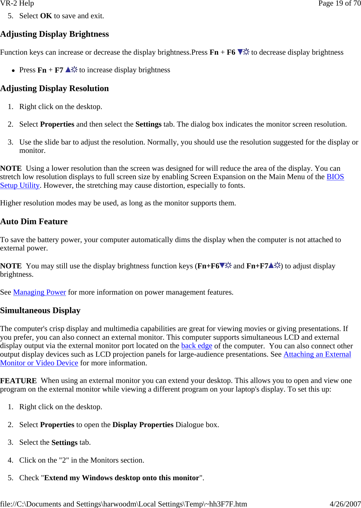
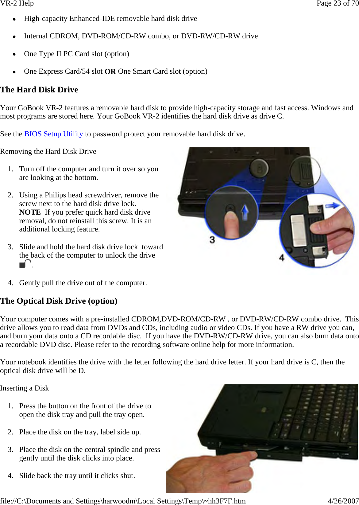
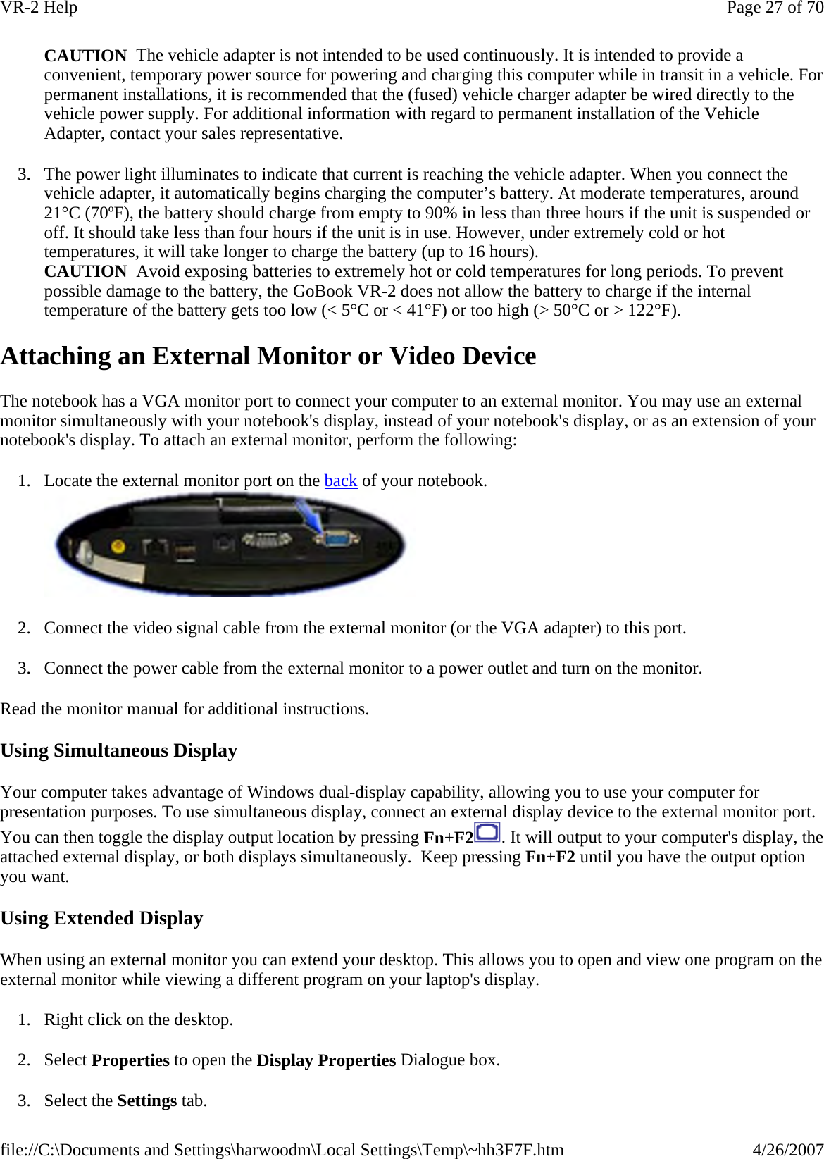
![Fax Branding The Telephone Consumer Protection Act of 1991 makes it unlawful for any person to use a computer or other electronic device to send any message via a telephone fax machine unless such message clearly contains in a margin at the top or bottom of each transmitted page or on the first page of the transmission, the date and time it is sent and an identification of the business or other entity, or other individual sending the message and the telephone number of the sending machine or such business, other entity, or individual. In order to program this information into your fax machine, you should complete the following: This information is entered through the FAX application software you have installed. Consult your FAX software documentation for instructions about entering this information. Warnings and Cautions WARNING It is important that only authorized GD-Itronix personnel attempt repairs on GD-Itronix equipment as this might void any maintenance contract with your company. Unauthorized service personnel might be subject to shock hazard on some GD-Itronix equipment if removal of protective covers is attempted. The product you have purchased is powered by a rechargeable battery. The battery is recyclable and, under various state and local laws, it may be illegal to dispose of this battery into the municipal waste stream. Do not crush the battery or place it in a fire. Check with your local solid-waste officials for details on recycling options or proper disposal. CAUTION Internal components of the GoBook VR-2 (IX605) computer will be damaged if exposed to contaminants. When dust covers, the PC card door, or the bottom access panel are open on the computer, shield the unit from all contaminants such as liquids, rain, snow, and dust. Internal radio(s) may have an individual FCC Identifier which are not applicable to this configuration. Only the FCC ID shown on the label located on the bottom of the IX605 Laptop PC is applicable. The IX605 computer must not be co-located or operating in conjunction with any other antenna or transmitter than specified in the filing . This device may contain a WLAN radio transmitter , a WAN radio transmitter and a PAN radio transmitter. To comply with FCC RF exposure requirements when using the WAN radio transmitter, a minimum separation distance of 20 cm must be maintained between the between the center of the display screen and all users/bystanders. When using the WLAN transmitter, a minimum separation distance of 20 cm must be maintained between the upper right and left edges of the display screen and all users/bystanders. When using the Pan transmitter, a minimum separation distance of 20 cm must be maintained between the lower left edges of the Keyboard and all users/bystanders. The WAN radio and WLAN/PAN transmitter should be turned off before carrying the Laptop PC order to comply with FCC RF exposure requirements. "The equipment has been approved to [Commission Decision "CTR21"] for pan-European single terminal connection to the Public Switched Telephone Network (PSTN). However, due to differences between individual PSTNs provided in different countries the approval does not, of itself, give an unconditional assurance of successful operation on every PSTN network termination point. In the event of problems, you should contact your equipment supplier in the first instance. This product is intended to be supplied by a Listed Power Unit and output rated 19 V dc, 3.42 A. CAUTION Always disconnect all telephone lines from the wall outlet before servicing or disassembling this equipment. CAUTION To reduce the risk of fire use only a No. 26 AWG or larger telecommunication line cord.Page 69 of 70VR-2 Help4/26/2007file://C:\Documents and Settings\harwoodm\Local Settings\Temp\~hh3F7F.htm](https://usermanual.wiki/General-Dynamics-Itronix/IX-BR-51.User-Manual-1/User-Guide-891512-Page-69.png)