General Dynamics Itronix IX-BR-51 IX-BTBR51 User Manual 1
General Dynamics Itronix Corporation IX-BTBR51 1
Contents
- 1. Radio Specific Safety Information
- 2. User Manual 2
- 3. User Manual 1
User Manual 1

Getting Started
Congratulations on your purchase of the GoBook VR-2 computer! Your new GoBook VR-2 features the most
innovative advances in portable computing technology. It combines state-of-the-art ergonomics with sophisticated
architecture to provide you with a personal computer that is compact, powerful, and easy to use.
Designed for a wide range of general, business, and personal productivity applications, the semi-rugged, wireless
ready GoBook VR-2 is an ideal choice wherever you need a computer; in the office, at home, and on the road.
Your GoBook VR-2 is both expandable and portable, supporting the features you expect in a desktop computer but
with the mobility of a laptop.
This online document, GoBook VR-2 Help, contains all the information you need to set up and use your GoBook
VR-2. For information on printing, navigating or otherwise using GoBook VR-2 Help, see the How to Use This Help
System topics. If you have suggestions for how we may improve this document, please see Documentation
Feedback.
Unpacking Your System
Inside your packaging you will find:
Standard Parts
Standard Features
Optional Features
Optional Parts and Accessories
Where to Look For Information
About Your Com
p
ute
r
Pa
g
e 1 of 70V
R
-2 Hel
p
4/26/2007file://C:\Documents and Settin
g
s\harwoodm\Local Settin
g
s\Tem
p
\~hh3F7F.htm
About Windows
The First Time. . .
Before using your computer, install the battery and then attach the computer to AC power.
Installing the Battery:
Attaching AC Power:
Begin Using the Computer
1. Open the display to a comfortable viewing angle.
2. Press the power switch to turn on the power.
The POST (power-on self-test) routine executes and Windows begins loading.
1. Line up the battery connectors.
2. Press gently on the battery until it clicks
into place.
3. Slide the battery locks toward the outside
of the computer to lock the battery and
ensure they latch completely.
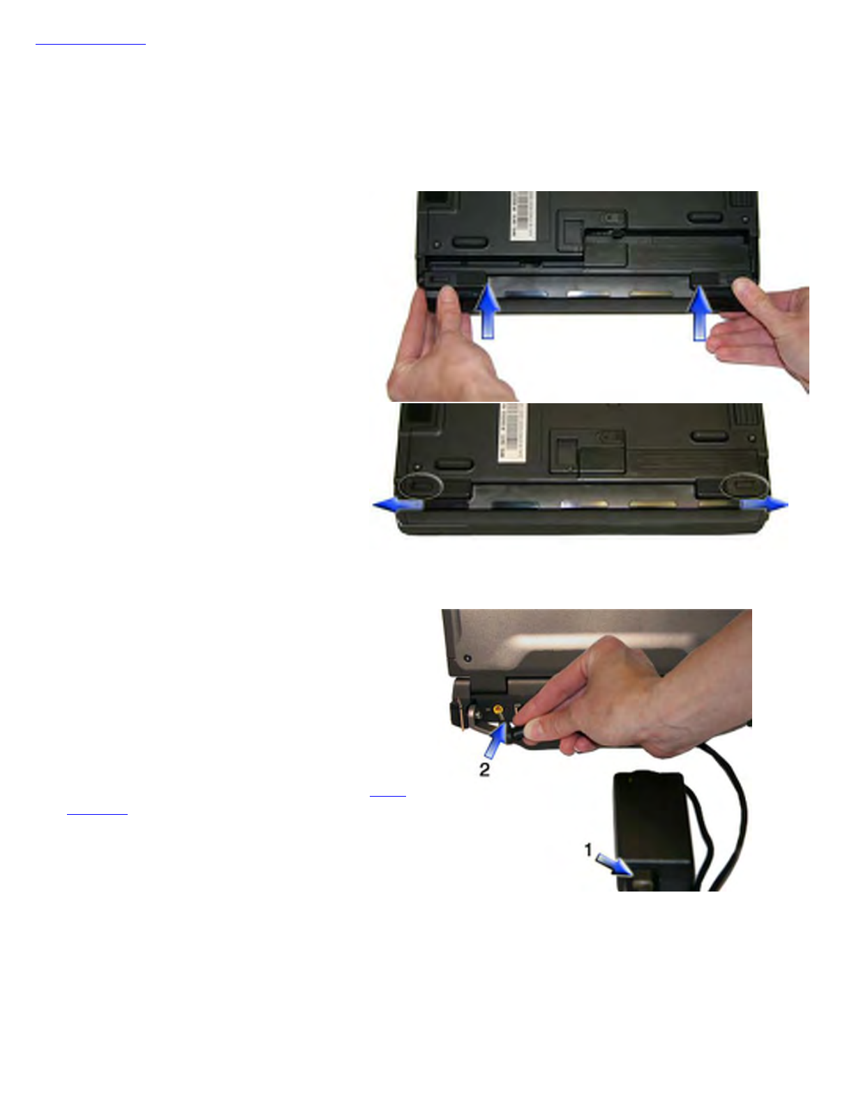
1. Connect the AC adapter power cord to the AC
adapter.
2. Connect the AC adapter to the DC power port on
the back of your computer.
3. Connect the AC adapter power cord to a properly
grounded AC outlet.
NOTE It is recommended you use a quality surge
protector.
Pa
g
e 2 of 70V
R
-2 Hel
p
4/26/2007file://C:\Documents and Settin
g
s\harwoodm\Local Settin
g
s\Tem
p
\~hh3F7F.htm

NOTE When using a battery pack for the first time, it is recommended that you calibrate the battery so the gas
gauge accurately displays battery capacity.
Turning off Your Computer
Turning off the computer properly is important to maintaining your computer. Select Start, Shut Down and follow
the instructions on the screen.
If you are going to be away from the computer for a short period, there are ways to conserve power without shutting
down the system. See Managing Power and Battery Tips for details.
NOTE If you are unable to shut down your computer normally, follow the instructions in Troubleshooting.
NOTE If you are using an office or vehicle dock, please refer to Undocking the VR-2 in the Optional Equipment
and Accessories section.
CAUTION Shutting off the computer improperly may result in data loss.
Startup Problems?
If your computer does not startup properly, try these solutions.
zConnect the AC adapter to charge the battery if it is not charged.
NOTE If the AC adapter is connected and functioning properly, the Power LED on the AC adapter should be
lit as well as the External Power LED on the GoBook VR-2.
zIf the AC adapter is connected but the unit will still not turn on, make sure the electrical outlet you are using
works.
zCheck to make sure the battery is installed and charged properly.
zIf the battery does not begin charging, remove the battery, connect the AC adapter, and turn on the computer
by pressing the Power Button. Reinstall the battery. The Battery LED is a steady green while the battery
is charging.
The Troubleshooting section lists additional solutions you can try.
Safety
Read these instructions carefully and save them. Following these guidelines will help prevent damage to your
computer and help protect your personal safety.
zFollow all warnings and instructions marked on the product and noted in this documentation, including the
Notices and Compliance section
zFollow all warnings and instructions noted in Windows Help and Support, found on the Start Menu
zThe first time you use your computer, we recommend that you carefully read the section on Power
Management to familiarize yourself with basic battery information and ensure optimum performance
zWARNING! There is danger of explosion if the battery is incorrectly replaced. Replace only with the same
or equivalent type recommended by the manufacturer. Dispose of used batteries according to the
manufacturer's instructions
Pa
g
e 3 of 70V
R
-2 Hel
p
4/26/2007file://C:\Documents and Settin
g
s\harwoodm\Local Settin
g
s\Tem
p
\~hh3F7F.htm

zWARNING! Batteries may explode if not handled properly. Do not disassemble or dispose of them in fire.
Keep them away from children and dispose of used batteries promptly
zUnplug the computer from the power outlet before cleaning. Use a damp cloth for cleaning. Do not use
aerosols, solvents, or strong detergents
zCAUTION The computer may be damaged if exposed to contaminants. Shield the unit from all contaminants
such as liquids, rain, snow, and dust
zSlots and openings in the computer case are for ventilation purposes. Do not block or cover these openings or
the system could overheat
zDo not place the product on a soft surface such as a bed, sofa, or rug where the ventilation slots and openings
may be blocked
zDo not place this product near or over a radiator or heat register
zDo not place this product in a built-in installation unless proper ventilation is provided
zDo not operate the computer at temperatures above 140°F (60°C) or below -4°F (-20C)
zDo not store the computer at temperatures above 140°F (60°C) or below -67°F (-55°C)
zDo not step on or place anything on the power cord
zIf you use the computer with an extension cord, ensure that the total ampere ratings of all the devices sharing
the extension do not exceed the rating of the extension cord or the rating of the wall outlet
zDo not push foreign objects into the computer through any of the slots or openings. Dangerous voltages are
present, which could cause electric shock, fire, or damage sensitive components
zThe computer's keyboard is designed to withstand spills. If a spill occurs, power off the computer and wipe it
down before continuing to use the computer
zFor best results, use a power strip with a built-in surge protector. Do not use inferior extension cords as this
may result in damage to your computer
zDo not attempt to service this product yourself, as opening or removing covers may expose you to dangerous
voltage points or other risks. Refer all servicing to qualified service personnel
zUnplug this product from the wall outlet and refer servicing to qualified service personnel under the following
conditions:
{When the power cord or plug is damaged or frayed
{If liquid has been spilled into the product
{If the product has been exposed to rain or water
{If the product does not operate normally when the operating instructions are followed. Adjust only those
controls that are covered by the operating instructions since improper adjustment of other controls may
result in damage and will often require extensive work by a qualified technician to restore the product to
normal condition
{If the
p
roduct has been dro
pp
ed or the cabinet has been dama
g
e
d
Pa
g
e 4 of 70V
R
-2 Hel
p
4/26/2007file://C:\Documents and Settin
g
s\harwoodm\Local Settin
g
s\Tem
p
\~hh3F7F.htm

{If the product exhibits a distinct change in performance, indicating a need for service
zDo not upgrade or service this computer without prior authorization from the manufacturer. Damage caused
by servicing that is not authorized may void your warranty
zBefore performing any manufacturer authorized service or upgrade, first follow these instructions:
{Prevent damage from static electricity by following ESD precautions
{Place the computer on a clean, flat surface
{Turn off the computer and disconnect the power supply
{Undock the computer if it is in a docking device (such as an office dock or vehicle dock)
{Disconnect any attached peripherals
{Disconnect any attached network, telephone or telecommunication line
{Remove any PC Cards, EXPRESS Cards, Smart Cards, CDs, DVDs or any other media in your
computer's slots or bays
{Remove the battery (See Battery Removal)
{Remove the hard drive (See Hard Disk Drive Removal)
Tips for New Owners
zTake responsibility for backup
Back up files often. Users who need to manage large amounts of data may wish to use backup devices
zDon't leave passwords anywhere on your notebook or carrying case
zBe careful when placing your notebook on an airport security conveyor belt
In most airports, security conveyor belts are safe for computers. If you are not sure, ask the security staff. You
should keep a close eye on your computer
zTape your business card to the notebook and accessories
In the workplace, notebooks and accessories may often look exactly alike, leading to equipment mix-ups.
Prevent such mix-ups by placing your name on your equipment
zInstall antivirus software
zConsider using a lock
For added security, consider purchasing a Kensington lock to put into the Security Slot on the left side of your
computer. Use the Kensington lock to secure the computer to a desk or table
zDevelop ergonomic work habits
The science of ergonomics studies the relationship between health and a suitable work environment. For more
information on ergonomics, contact your nearest computer bookstore, or local library. The Internet also has
information on this and other related subjects
NOTE Using a computer for extended periods of time with a poor workstation setup and incorrect work
habits can cause health
p
roblems
Pa
g
e 5 of 70V
R
-2 Hel
p
4/26/2007file://C:\Documents and Settin
g
s\harwoodm\Local Settin
g
s\Tem
p
\~hh3F7F.htm
Getting Familiar with Your Computer
Before you begin using your GoBook VR-2, read this section to familiarize yourself with its main features and
components.
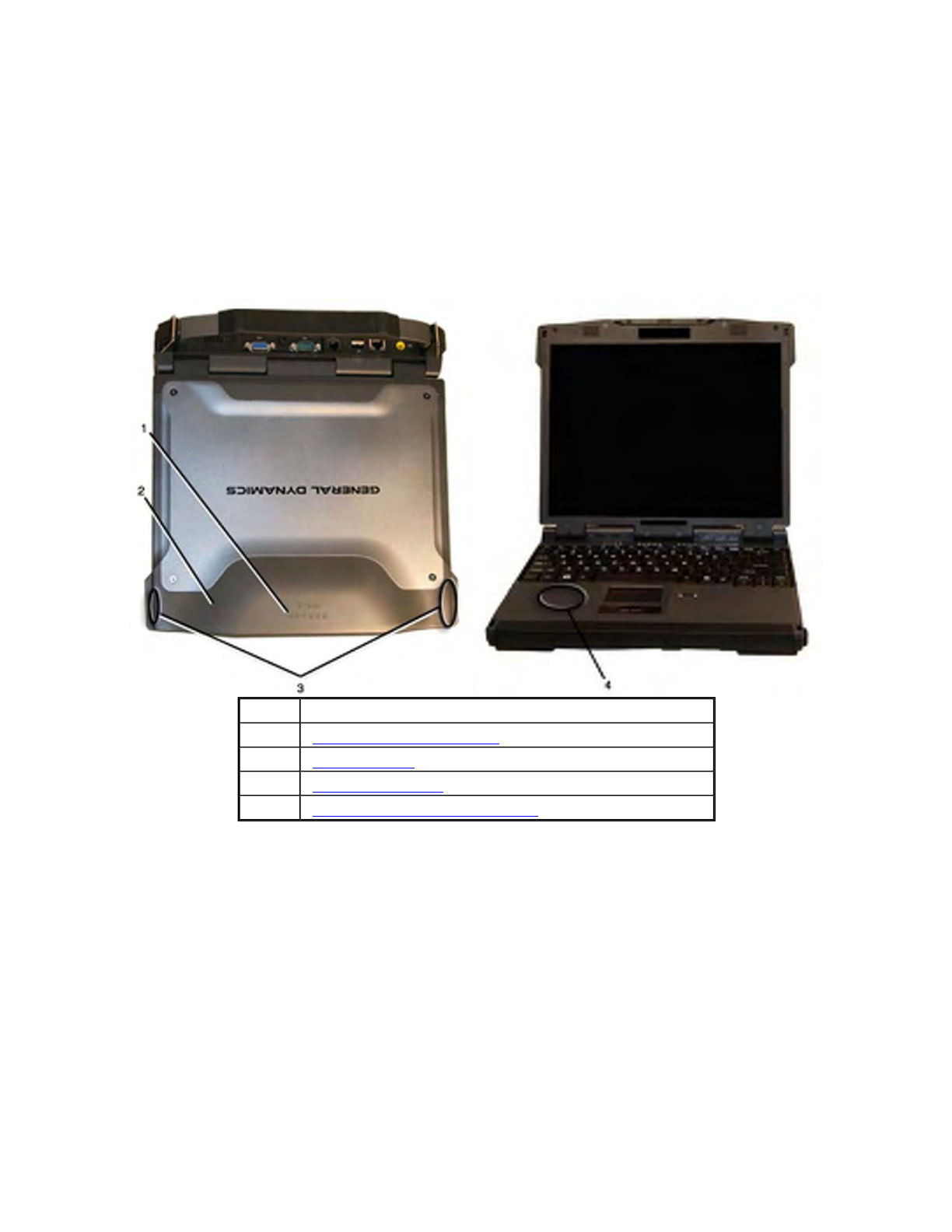
Tour of Your Computer
This section shows all views of your computer with a summary of key features.
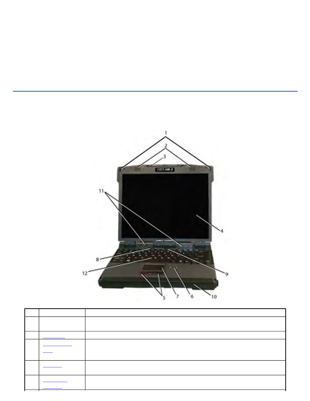
Front View
Hover the mouse over each number on the picture to see a description
# Feature Description
1 Display
Latches Two display latches hold the display when closed.
2 Speakers Integrated Stereo speakers for audio output
3 Pen / Stylus
Slot A custom touch screen pen (stylus) is supplied with each unit equipped with
the optional touch screen and is stored in a slot located on the left side of the
display
4 Display 13.3-inch, Enhanced XGA, outdoor-viewable, color display with an optional
integrated touch screen
5 Touchpad
Buttons Use like the buttons on a mouse
GoBook VR-2 Help
Pa
g
e 6 of 70V
R
-2 Hel
p
4/26/2007file://C:\Documents and Settin
g
s\harwoodm\Local Settin
g
s\Tem
p
\~hh3F7F.htm
Top View
Hover the mouse over each number on the picture to see a description
6
Fingerprint
Scanner The optional swipe style fingerprint scanner can be used for all standard
security needs
7 Touchpad Use for navigation
8 Power Button Turns computer on or off
9
Application
Launch Button Programmable button
10 Battery Removable Lithium-Ion battery
11 Keyboard Task
Lights Two task lights located in the display hinges directly below the display
illuminate the keyboard to permit typing in a dimly lit or darkened
environment.
12 Keyboard Standard keyboard with embedded numeric keypad
# Feature Description
1 CRMA Express
Antenna Antenna for WAN Communications
2 GPS Antenna Antenna for GPS Receiver
72_0133_001
2007.03.19
© 2007 GD-Itronix Cor
p
oration. All ri
g
hts reserved.
Pa
g
e 7 of 70V
R
-2 Hel
p
4/26/2007file://C:\Documents and Settin
g
s\harwoodm\Local Settin
g
s\Tem
p
\~hh3F7F.htm
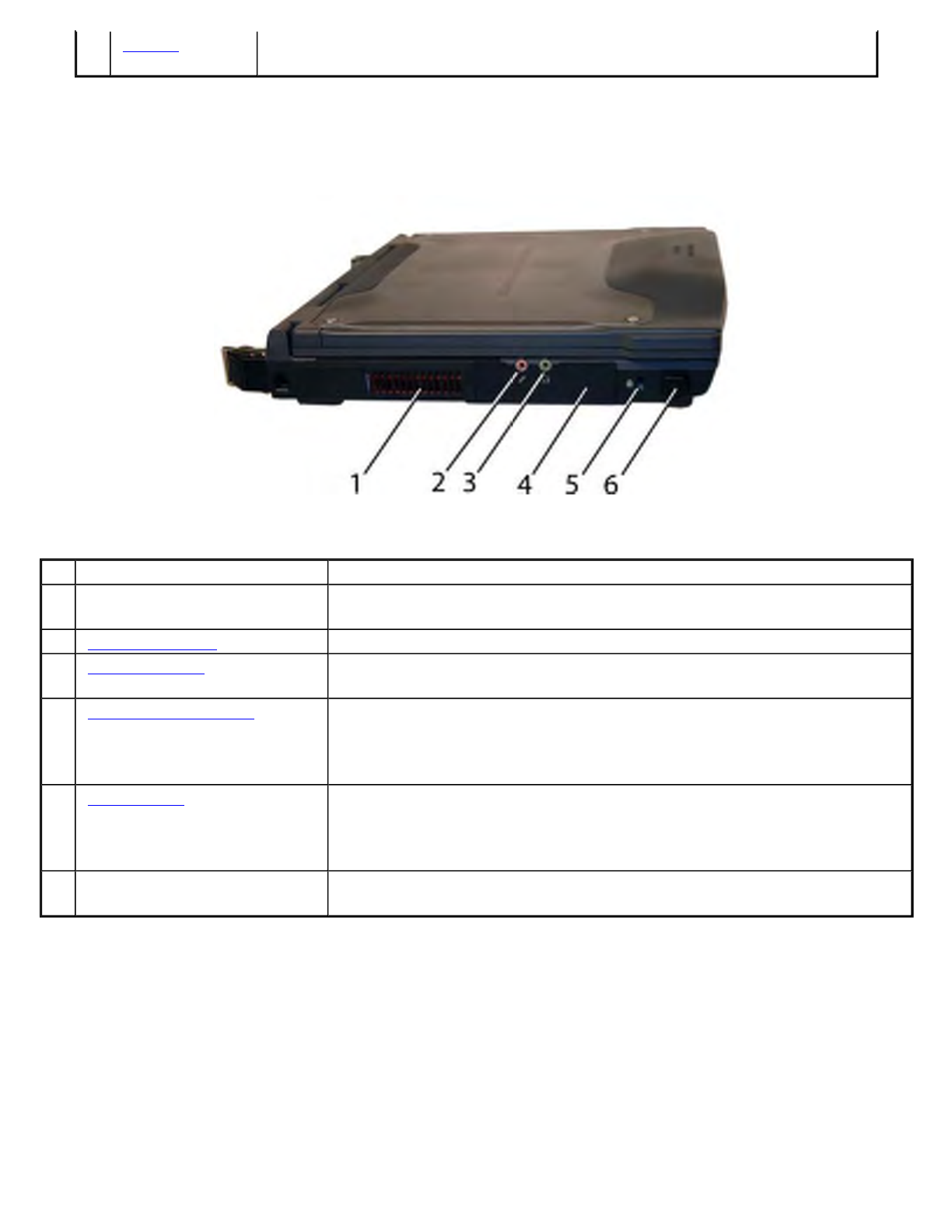
Left Side View
Hover the mouse over each number on the picture to see a description
Right Side View
Hover the mouse over each number on the picture to see a description
3 WLAN
Antennas Antenna for WLAN Communications
# Feature Description
1 Cooling Fan Exhaust Cooling Fan exhaust area. Do Not Block. This area may become hot as
air vents from the computer
2 Microphone Jack Connect a microphone to this jack to record audio
3 Audio Out Jack Connect external speakers or a stereo headset to this jack to listen to
multimedia
4 Removable Hard Disk The removable Hard Disk Drive is located on the left side of the unit. The
latch that secures the Hard Dick Drive is located on the bottom of the unit.
NOTE: make sure the unit is powered off before removing the Hard Disk
Drive to prevent data corruption
5 Security Slot The Security Slot can be used with a standard laptop-locking device, such
as a Kensington Lock. You can connect the GoBook VR-2 to a large
object with the lock to prevent theft of your GoBook VR-2. See the
documentation that comes with your lock for more information
6 Front Handle Mount The front soft handle mount, located on both sides of the unit, is used with
the optional soft handle
Pa
g
e 8 of 70V
R
-2 Hel
p
4/26/2007file://C:\Documents and Settin
g
s\harwoodm\Local Settin
g
s\Tem
p
\~hh3F7F.htm

Back Edge View
Hover the mouse over each number on the picture to see a description
# Feature Description
1 Front Handle Mount The front soft handle mount, located on both sides of the unit, is used with the
optional soft handle
2 CRMA Express CRMA Express Radio bay
3 Optical Disk Drive CD-RW, DVD/CD-RW, or DVD-RW/CD-RW
4 Smart Card Reader
or
EXPRESS Card Slot
Smart Card Reader or EXPRESS Card
5 PC Card Slot Use this slot for PC Card devices
# Feature Description
1 DC-in Jack Connects to an AC adapter
2 Network Jack (RJ45/LAN) Connects to an Ethernet-based network. Connection speed is 10/100/1000
Mbps
3 Two 2.0 USB Ports Connects to USB devices (e.g., USB digital camera)
4 Modem Jack (RJ11) Connects a phone line to the internal fax/data modem. It can transmit data
Pa
g
e 9 of 70V
R
-2 Hel
p
4/26/2007file://C:\Documents and Settin
g
s\harwoodm\Local Settin
g
s\Tem
p
\~hh3F7F.htm
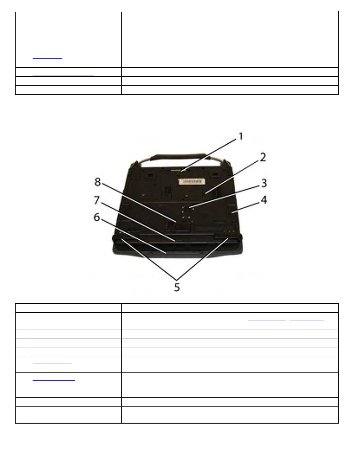
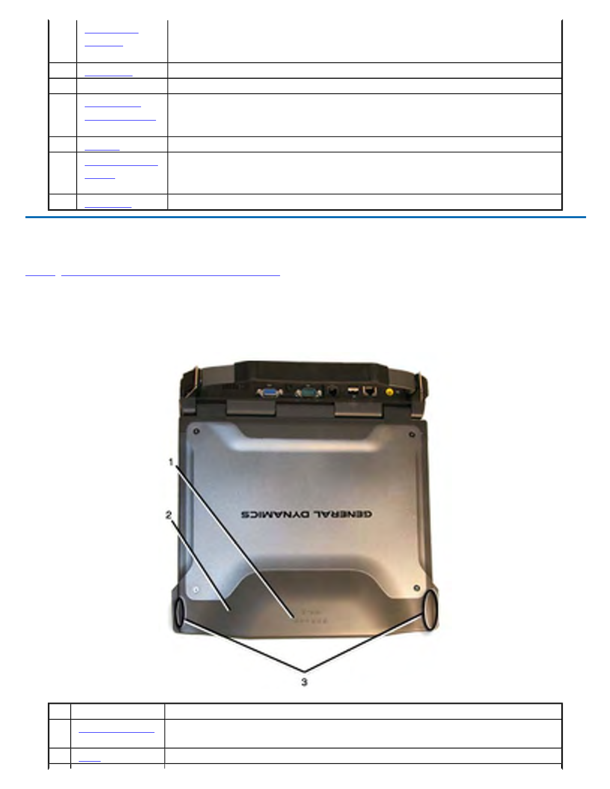
Bottom View
Hover the mouse over each number on the picture to see a description
using the 56 Kbps V.90 or V.92 protocol, and send and receive faxes at
14.4 Kbps.
NOTE In some countries, local regulations may not permit the use of the
fax/modem designed for this system. In this case, you may use a
PCMCIA modem
5 Serial Port Connects your computer to serial devices such a fax/modem or a serial
mouse. This port is identified as COM3 and is UART 16550A compatible
6 External Monitor Port Connects to a display monitor (up to 2048x1536 resolution)
7 Cooling Fan Intake Air intake for fan. Do NOT block this area
8 Hard Handle (optional) Carrying handle
# Feature Description
1 Docking Connector 84-pin cradle connector that mates with the Vehicle Dock, Office Dock,
and Mini-Dock
2 Memory compartment User expandable memory slot
3 Hard Disk Lock Slide this to lock or unlock the hard disk drive
4 Hard Disk Drive Removable hard disk drive for data storage
5 Battery Locks Slide these locks toward the outer edges of the computer to lock the
battery
6
Pen/Stylus Slot A custom touch screen pen (stylus) is supplied with each unit equipped
with the optional touch screen and is stored in a slot located on the left
side of the display
7 Battery Lithium-Ion Smart Battery
8 Battery Release Latch Slide this latch to the left to remove the battery. NOTE You must first
unlock the battery
Pa
g
e 10 of 70V
R
-2 Hel
p
4/26/2007file://C:\Documents and Settin
g
s\harwoodm\Local Settin
g
s\Tem
p
\~hh3F7F.htm

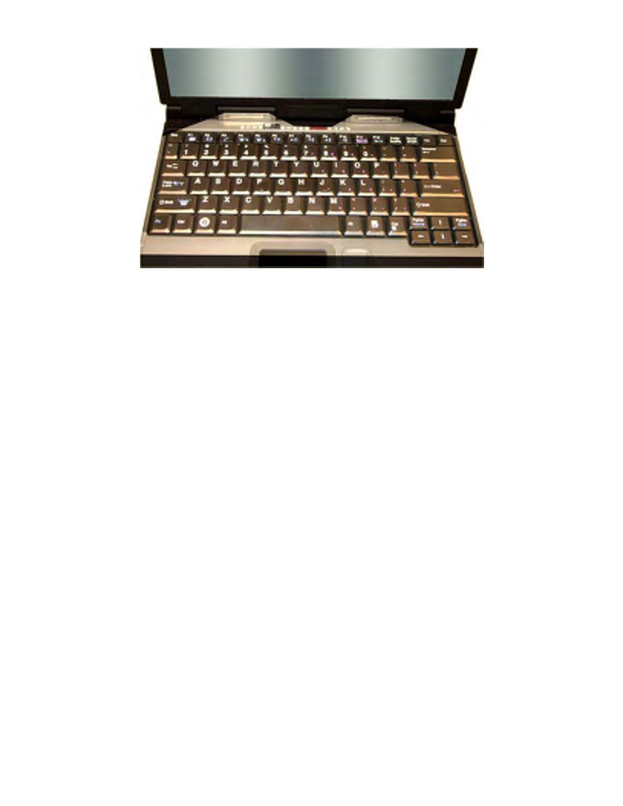
Keyboard Basics
The GoBook VR-2 features:
zFull size keys on a 85-key keyboard
zTwelve function keys
zApplication launch button (programmable button)
zEmbedded numeric keypad
zUSB port that enables you to connect an external keyboard
Keyboard ergonomics
Located below the keyboard, the wide palm rest is ergonomically designed to provide you with a very comfortable
p
lace to rest your hands while you type.
Primary Keys
Key Description
Alt The Alt (alternate) key is used with other keys to perform special tasks. On some
operating systems pressing Ctrl+Alt+Del twice soft reboots the computer
Backspace The Backspace key, sometimes represented on the keyboard as a left arrow, moves
the cursor one position to the left. The character to the left of the cursor is erased
Caps Lock Pressing the Caps Lock key one time locks keys A through Z in the UPPER CASE
position. Pressing the Caps Lock key again returns the letters to lower case. While
in the upper case mode, pressing the Shift key results in lowercase characters when
entered. You still have to use the Shift key to display characters located on the upper
portion of the keyboard. For example, press Shift+8 to type an asterisk (*), even
when the Caps Lock key is activated
The Caps Lock LED lights when the keyboard is in Caps Lock mode
Ctrl The Ctrl (control) key works with other keys to perform a variety of functions
Enter The Enter key signals the computer that you have completed your entry. This is
your way of telling the computer to process the information that you have entered
Esc The Esc (escape) key allows you to exit a pop-up window or message box
PrtSc In Windows, pressing the PrtSc (print screen) key or ALT+PrtSc key copies the
current screen or window to the clipboard so you can paste it into documents
Shift The Shift key changes the keys A through Z to the UPPER CASE position. When
you press an alphabetic key, the character appears as a capital letter. When you press
Shift with other keys, the characters on the upper part of the keys appear. For
example, pressing Shift+7 displays an ampersand (&)
Fn Some special Fn (function) keys have been established to perform important tasks
when pressed and held with the Fn key. These keys are described later in this
document. The Fn key legend is color keyed to other special keys on the keyboard
SPACEBAR Use the SPACEBAR to enter a space and move the cursor one character to the right
Tab The Tab key moves the cursor to the next tab stop or field. Tab stops are defined by
your operating system or application program. Press the Tab key to move from one
field or text box to another
Pa
g
e 11 of 70V
R
-2 Hel
p
4/26/2007file://C:\Documents and Settin
g
s\harwoodm\Local Settin
g
s\Tem
p
\~hh3F7F.htm
Arrow Keys
The arrow keys are defined by the software
application.
The UP ARROW key usually moves the cursor up one line. In some cases, you can use the up arrow to make
selections from menus and scrollable list boxes.
The DOWN ARROW key usually moves the cursor down one line. In Windows, you can use the down arrow to
make selections from menus and scrollable list boxes.
The RIGHT ARROW key usually moves the cursor one character position to the right.
The LEFT ARROW key usually moves the cursor one character position to the left.
Function Keys and Key Combinations
When using function keys, press and hold the Fn key before pressing the other key in the key combination.
Function
Key Function Icon Description
Fn+F1 Screen
blank Turns off the display screen backlight and turns
off the external monitor, if attached. Press any
key to turn it back on.
Fn+F2 Display
toggle Switches the display output between the display
screen, external monitor (if connected) and both
the display screen and external monitor
NOTE When a DVD or VCD is playing, this
hotkey is disabled.
Fn+F3 Standby Puts the computer in standby mode, which can be
defined with Power Saver.
Fn+F4 Task lights
Brightness
Down Dims the keyboard task lights
Fn+F5 Task lights
Brightness
Up Increases the brightness of the keyboard task
lights
Fn+F6 Brightness
Down Decreases the screen brightness
Fn+F7 Brightness
Up Increases the screen brightness
Fn+F8 Audio
Volume
Down
Decreases the audio volume
Fn+F9 Audio
Volume Up Increases the audio volume
Fn+F10 Speaker
on/off Turns the speakers on and off; mutes the sound
Fn+F11 Num Lock Num Lk Enters Numlock mode. Use the embedded
numeric keypad for quick number entry. Other
keys function as normal.
Fn+F12 Scroll Lock Scr Lk Scroll Lock
Pa
g
e 12 of 70V
R
-2 Hel
p
4/26/2007file://C:\Documents and Settin
g
s\harwoodm\Local Settin
g
s\Tem
p
\~hh3F7F.htm
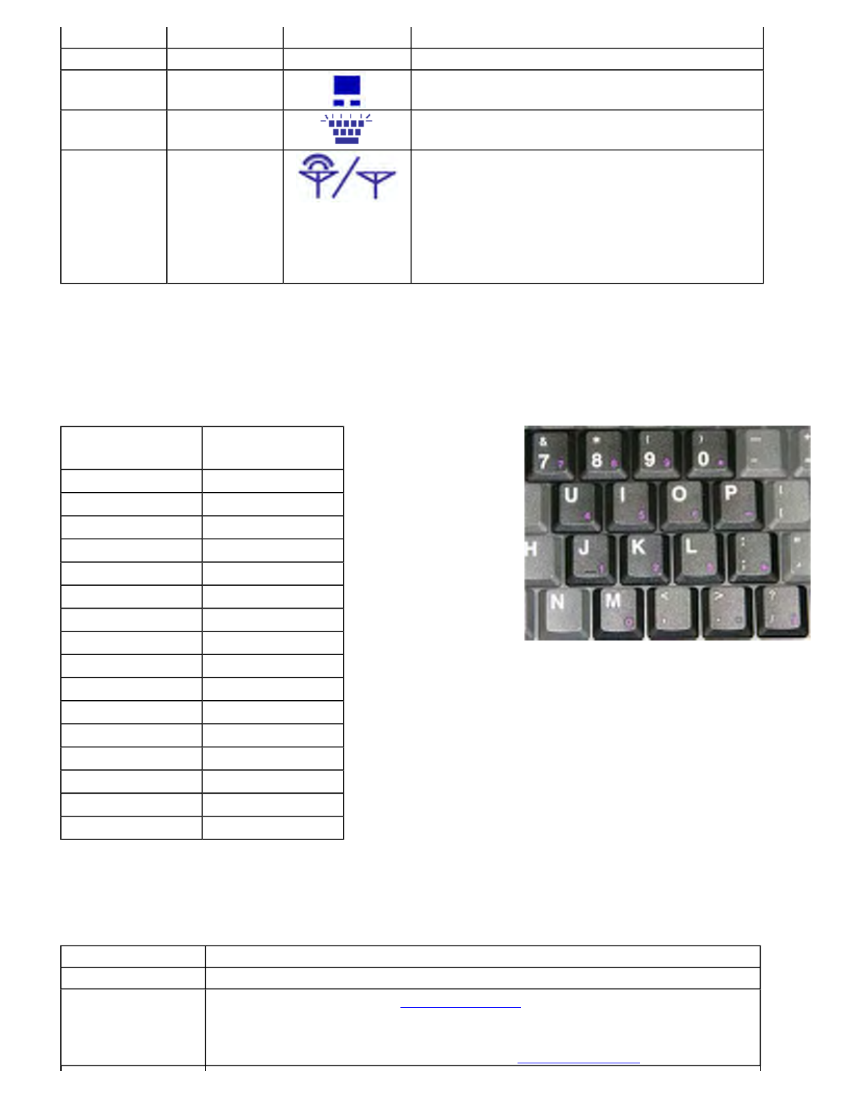
Numeric Keypad
The embedded numeric keypad consists of sixteen keys that make number intensive input more convenient. It is
indicated by small characters located on the lower right corner of the key. Press FN+F11 (NumLk) to enable or
disable the numeric keypad.
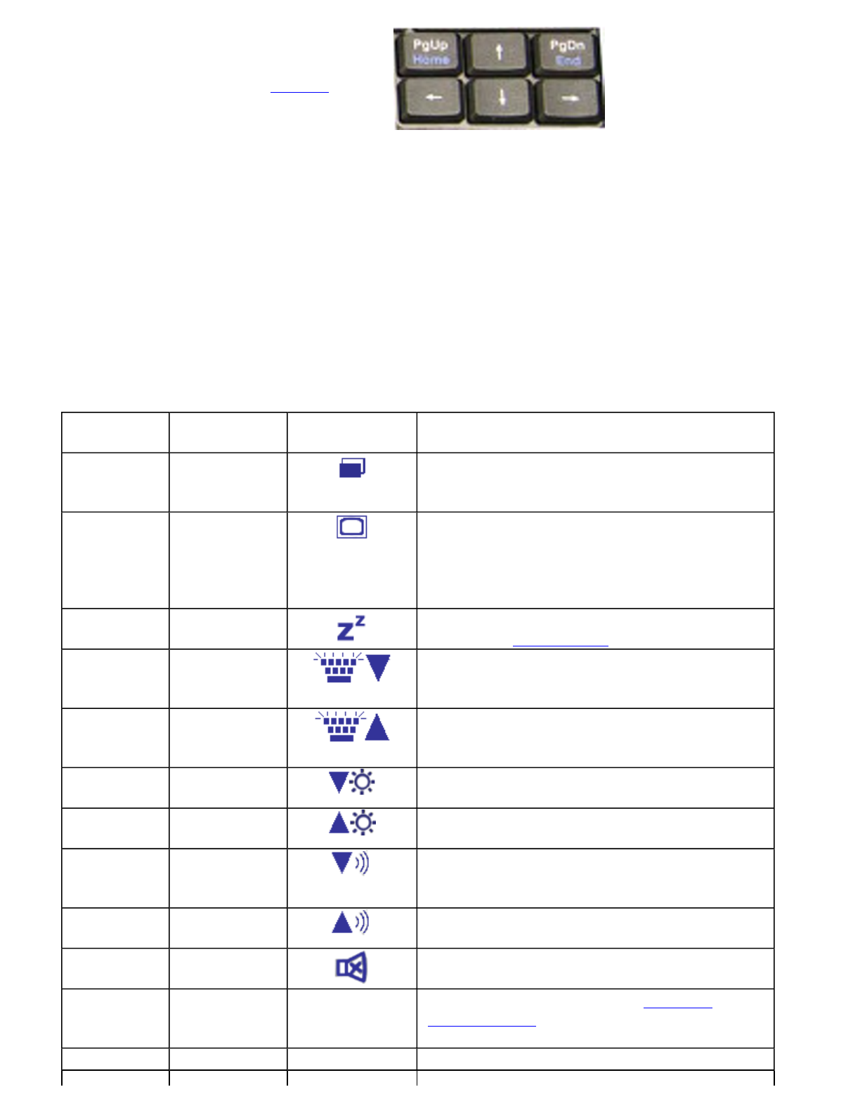
Lock Keys
The keyboard has three lock keys which you can toggle on and off.
Fn+PgUp Home Home Functions as the “Home” key
Fn+PgDn End End Functions as the “End” key
Fn+ Right
Ctrl Touchpad
on/off Toggles the touchpad on and off
Fn+ Left
Shift Keyboard
Task Lights Toggles the keyboard task lights on and off
Fn+Caps
Lock Wireless
Radio
On/Off
Switch
Also known as "Airplane Mode". Toggles the
power on and off to all radio devices. The radio
devices include GPS, Bluetooth, WLAN,and
WWAN radios.
NOTE If radio wakeup is enabled, radio power
will turn back on before the system suspends.
Standard Key Key with Num
Lock On
7 7
8 8
9 9
0 *
U 4
I 5
O 6
P -
J 1
K 2
L 3
; +
M 0
. .
/ /
Enter Carriage Return
Lock Key Description
Caps Lock When Caps Lock is on, all alphabetic characters typed are in uppercase
Num Lk
(Fn-F11) When Num Lock is on, the embedded keypad is in numeric mode. The
keys function as a calculator (complete with the arithmetic operators +, -,
*, and /). Use this mode when you need to do a lot of numeric data entry.
Alternately, connect an external keypad. See External keyboard
Pa
g
e 13 of 70V
R
-2 Hel
p
4/26/2007file://C:\Documents and Settin
g
s\harwoodm\Local Settin
g
s\Tem
p
\~hh3F7F.htm
Windows Keys
The keyboard has two keys that perform Windows-specific functions.
Application Launch Button
The Application launch button is the right button above the keyboard. Use an
application manager to program this button's function.
Keyboard Task Lights
Your GoBook VR-2 is equipped with two task lights located in the display hinges directly below the display. The
p
urpose of these task lights, or ‘headlights’, is to illuminate the keyboard to permit typing in a dimly lit or darkened
environment.
Scr Lk
(Fn-F12) Enters Scroll Lock mode. Scroll Lock varies between applications. It
does not work with some applications
Key Icon Description
Windows Logo Key Start button. Combinations with this key perform special
functions. Below are a few examples:
+ TAB (Activates next Taskbar button)
+ E (Opens My Computer)
+ M (Minimizes all Windows)
SHIFT + + M (Restores Minimized Windows)
+ R (Displays Run dialog box)
Refer to Keyboard Shortcuts in Windows Help and Support for
a complete list of Windows key combinations
Application Key Opens the application's context menu (same as right-click)
Pa
g
e 14 of 70V
R
-2 Hel
p
4/26/2007file://C:\Documents and Settin
g
s\harwoodm\Local Settin
g
s\Tem
p
\~hh3F7F.htm
To Use the Headlights (task lights)
1. Press Fn+Shift to toggle the lights on or off.
NOTE If the light does not come on, try adjusting the headlights by pressing Fn+F5 to turn the brightness up.
2. Press Fn+F4 to dim the headlights
3. Press Fn+F5 to brighten the headlights
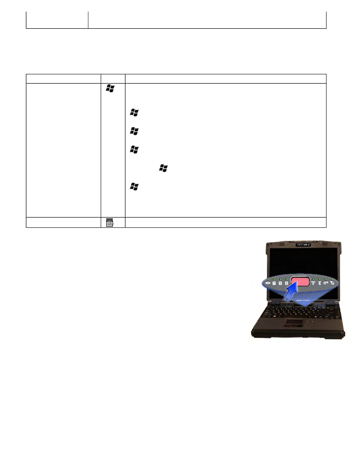
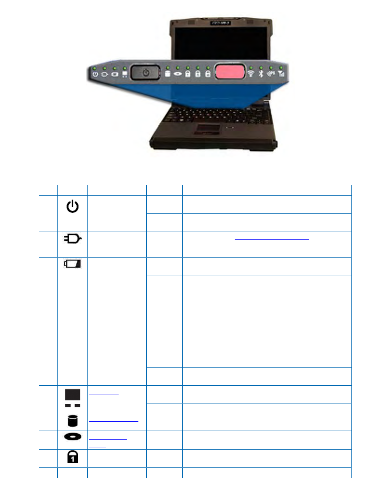
LED Status Indicators
Thirteen easy-to-read LEDs (Light Emitting Diodes) under the display screen indicate activity status for common
functions
Hover the mouse over each LED and S
y
mbol on the picture to see a description
Pa
g
e 15 of 70V
R
-2 Hel
p
4/26/2007file://C:\Documents and Settin
g
s\harwoodm\Local Settin
g
s\Tem
p
\~hh3F7F.htm
.
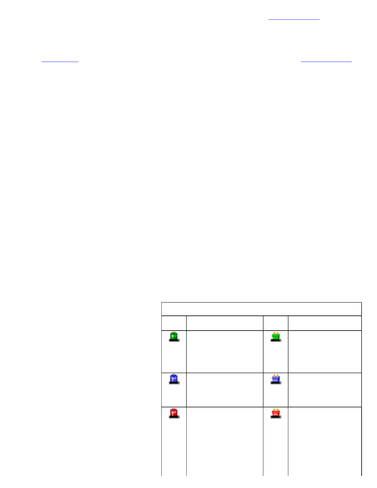
# Icon Function LED Description
1
Power Steady
Green Computer is on and operating
Blinking
Green Computer has suspended to RAM
2 External Power Steady
Green Power is on and external power is applied from the AC
Adapter connected to a wall outlet, a vehicle-mounted
dock, a vehicle power adapter, or an office dock
3 Battery Power Steady
Green Battery is charging
Blinking
Green Battery is low
NOTES
If the computer is not plugged into external power
within a few minutes, it will go into a Suspend Power
Mode
If the computer is radio-equipped and is in the middle
of communication, it will suspend power to the radio
when the battery is low. The computer must then be
plugged into external power to continue radio
communication
No Light The battery is fully charged or a main battery pack is
not fully inserted
4
Touchpad Steady
Green Touchpad is activated
No Light Touchpad is disabled
5 Hard Disk Drive Blinking
Green Computer is reading from, or writing to the built-in
hard disk
6 Optical Disk
Drive Blinking
Green Computer is reading information from the Optical Disk
Drive
7 Num Lock Steady
Green Keyboard is in Num Lock mode
Steady Keyboard is in Caps Lock mode
Pa
g
e 16 of 70V
R
-2 Hel
p
4/26/2007file://C:\Documents and Settin
g
s\harwoodm\Local Settin
g
s\Tem
p
\~hh3F7F.htm
NOTE Some of the features associated with these LEDs are options and may not be included in your computer's
configuration.
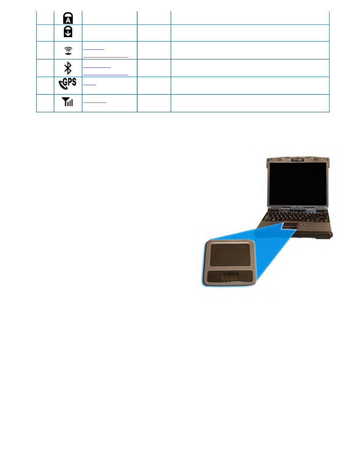
Touchpad
The built-in touchpad is a pointing device that senses movement
on its surface. This means the cursor responds as you move your
finger over of the touchpad. It also provides all the features of a
two-button mouse.
How to Use the Touchpad
1. First, place your fingers on the keyboard in the normal
typing position. The touchpad is easily accessible by
moving either your left or right thumb off the space bar
and onto the touchpad.
2. Gently move your thumb across the pressure-sensitive
touchpad in the direction you want the cursor to move.
The pad detects the change in pressure and moves the
cursor in the corresponding direction.
3. You can also make selections by double-tapping. This
function corresponds to double-clicking with a mouse. Once the cursor has been moved to the object you
want to select, lightly double-tap the pressure sensitive touchpad. This double-tapping on the touchpad selects
the desired item and prompts the software to perform the related operation.
Adjust the touchpad settings by selecting Settings, Control Panel, Mouse, Buttons. These settings allow you to
change the orientation from right-handed to left-handed, and fine-tune the pointer movement and timing of clicks.
Touchpad Precautions
The touchpad is a pressure-sensitive device. If not properly cared for, it can be easily damaged. Please take note of
the following precautions:
zMake sure the touchpad does not into come into contact with dirt, liquids or grease
zDo not touch the touchpad if your fingers are dirty
zDo not rest heav
y
ob
j
ects on the touch
p
ad or the touch
p
ad buttons
8 Caps Lock Green
9 Scroll Lock Steady
Green Keyboard is in Scroll Lock mode
10
WLAN
Communication Steady
Green Wireless LAN radio is on
11
Bluetooth
Communication Steady
Green Bluetooth radio is on
12 GPS
Communication Steady
Green GPS radio is on
13 WWAN
Communication Steady
Green WWAN radio is on
Pa
g
e 17 of 70V
R
-2 Hel
p
4/26/2007file://C:\Documents and Settin
g
s\harwoodm\Local Settin
g
s\Tem
p
\~hh3F7F.htm

zKeep your fingers dry and clean when using the touchpad and keep the touchpad dry and clean
zThe touchpad is sensitive to finger movements. It responds best to light touches. Tapping too hard will not
increase the touchpad's responsiveness
Touchpad Buttons
The buttons located directly below the touchpad are the same in function as those on a two-buttoned mouse.
Pressing these buttons makes selections, drags objects, or performs a variety of other functions depending on the
software.
To Select an Object
1. First move the pointer over the object you want to select
2. Press the left button one time. The functions of these buttons are software specific.
Double-Clicking
Double-clicking is a common technique for selecting objects or launching programs from icons. Once you have
moved the pointer over the object you wish to select, rapidly press the left button two times. This action is
commonly referred to as "double-clicking" an object.
Dragging
zMove the pointer to the desired location then press down the left button. While still holding down the left
button, move the pointer to the desired location. Release the button
zMove the pointer to the desired location. Tap the touchpad twice quickly as if you were double-clicking;
however, do not remove your finger after the second tap. Move the cursor to the desired location. Lift your
finger to finish dragging
Display
The GoBook VR-2 features a 13.3-inch, XGA, outdoor-viewable, color display with an optional integrated touch
screen. The Colorvue™ Transmissive display technology uses a built-in backlight for easy reading in most ambient
light conditions. The backlight remains on whenever the display is on. The transmissive display enhancement
p
rovides improved outdoor visibility and even works well in sunlight.
Calibrating the Touch Screen
Your computer has the Hi Bright 500NIT touch screen, allowing
you to start programs and input data using the approved pen
(stylus) that comes with the computer.
1. Remove the stylus pen from its slot on the top of the
display.
2. Select Start, All Programs, Touchkit, Configure Utility.
3. Select 4 pts Cal.
4. Touch and hold the tip of the pen to the center of each blinking symbol as they appear on the screen until
calibration is com
p
lete.
Pa
g
e 18 of 70V
R
-2 Hel
p
4/26/2007file://C:\Documents and Settin
g
s\harwoodm\Local Settin
g
s\Tem
p
\~hh3F7F.htm

5. Select OK to save and exit.
Adjusting Display Brightness
Function keys can increase or decrease the display brightness.Press Fn + F6 to decrease display brightness
zPress Fn + F7 to increase display brightness
Adjusting Display Resolution
1. Right click on the desktop.
2. Select Properties and then select the Settings tab. The dialog box indicates the monitor screen resolution.
3. Use the slide bar to adjust the resolution. Normally, you should use the resolution suggested for the display or
monitor.
NOTE Using a lower resolution than the screen was designed for will reduce the area of the display. You can
stretch low resolution displays to full screen size by enabling Screen Expansion on the Main Menu of the BIOS
Setup Utility. However, the stretching may cause distortion, especially to fonts.
Higher resolution modes may be used, as long as the monitor supports them.
Auto Dim Feature
To save the battery power, your computer automatically dims the display when the computer is not attached to
external power.
NOTE You may still use the display brightness function keys (Fn+F6 and Fn+F7 ) to adjust display
brightness.
See Managing Power for more information on power management features.
Simultaneous Display
The computer's crisp display and multimedia capabilities are great for viewing movies or giving presentations. If
you prefer, you can also connect an external monitor. This computer supports simultaneous LCD and external
display output via the external monitor port located on the back edge of the computer. You can also connect other
output display devices such as LCD projection panels for large-audience presentations. See Attaching an External
Monitor or Video Device for more information.
FEATURE When using an external monitor you can extend your desktop. This allows you to open and view one
p
rogram on the external monitor while viewing a different program on your laptop's display. To set this up:
1. Right click on the desktop.
2. Select Properties to open the Display Properties Dialogue box.
3. Select the Settings tab.
4. Click on the "2" in the Monitors section.
5. Check "Extend m
y
Windows deskto
p
onto this monitor".
Pa
g
e 19 of 70V
R
-2 Hel
p
4/26/2007file://C:\Documents and Settin
g
s\harwoodm\Local Settin
g
s\Tem
p
\~hh3F7F.htm

6. Select Apply and OK to save and exit.
7. Now you can drag the programs you want to view onto the external monitor.
Opening and Closing the Display
To open the display lid, slide the display lid latch to the right and lift up the lid, then tilt it to a comfortable viewing
p
osition.
To close the display lid, fold it down gently until the display lid latch clicks into place.
CAUTION To avoid damaging the display, do not slam it when you close it. Also, do not place any object on top
of the computer when the display is closed.
Lid Switch
Your computer has a lid switch that automatically suspends your computer when you close the display and resumes
it when you open the display.
To change the power management settings for the lid switch, perform the following:
1. On the System Tray area of the Taskbar, right-click the Power Saver icon ( or ).
2. From the menu, select Configure Power Settings.
3. Select the Advanced button.
4. Select what you want to happen when you close the display lid:
{Do nothing
{Sleep
{Hibernate
5. Check the Wakeup box if you want the computer to resume when you open the display lid.
Cursor Visibility
To improve the visibility of the mouse cursor, you should:
zEnable the “Pointer Trails” feature to add trailing cursors
zUse a slow or medium speed/sensitivity level
You can combine a higher level of acceleration with a slow or medium speed/sensitivity level. This allows you to
move the mouse cursor quickly by increasing your finger pressure, while still providing a finer degree of control
when you apply minimum pressure.
NOTE To change the speed of the mouse, from the Start Menu select Settings, Control Panel, and then choose
Mouse to make adjustments.
Memory
Pa
g
e 20 of 70V
R
-2 Hel
p
4/26/2007file://C:\Documents and Settin
g
s\harwoodm\Local Settin
g
s\Tem
p
\~hh3F7F.htm
The GoBook VR-2's memory capacity is 512 to 4096MB with one user accessible memory socket supporting a
512MB to 2048MB memory module. Please consult your dealer if you need to add more memory.
Refer to the Memory Upgrade section for information about replacing the memory module.
Audio
Your computer includes 16-bit high-fidelity stereo audio output and an integrated microphone. The speakers are
located above the display. The microphone is under the display.
You can attach external audio devices via the audio out jack on the left side of the computer.
Adjusting the Volume
zTo increase volume, press Fn+F9
zTo decrease volume, press Fn+F8
You can also adjust the volume with the Windows volume control applet located on the taskbar. However, the
volume control function keys override the Windows volume control applet. If your volume is too low or too high
after setting the volume in the applet, adjust the volume with the function keys.
The PC Card Slot
The computer has a built-in CardBus PC Card slot on the right side of the computer that can accommodate one Type
II PC Card. It accepts credit-card sized cards that enhance the usability and expandability of the computer. The PC
Card slot can be used as an interface between your computer and a variety of communications devices, such as
network adapters, SCSI adapters, or fax/modems. They can also be used to provide additional data storage capacity.
Please consult your dealer for PC Card options available that you can purchase for your computer.
NOTE Refer to your card's instructions on how to install and use the card and its functions.
Inserting a Card
1. The top side of a PC Card is usually identified with a
label. Insert the card into the slot with the top up and
the edge with pinhole contacts going in first. You will
feel some resistance as the card slides into the back of
the slot.
2. PC Cards require drivers, or a program that allows the
operating system to use a specific device. Many
drivers are included with Windows, but if not, you will
be prompted to install the driver included with your
card.
3. The computer will beep twice to indicate successful installation. A single beep means that there was a
problem recognizing the card.
NOTE Please read the instructions included with individual PC Cards. Some cards may be inserted with power on,
while others require that the computer be turned off.
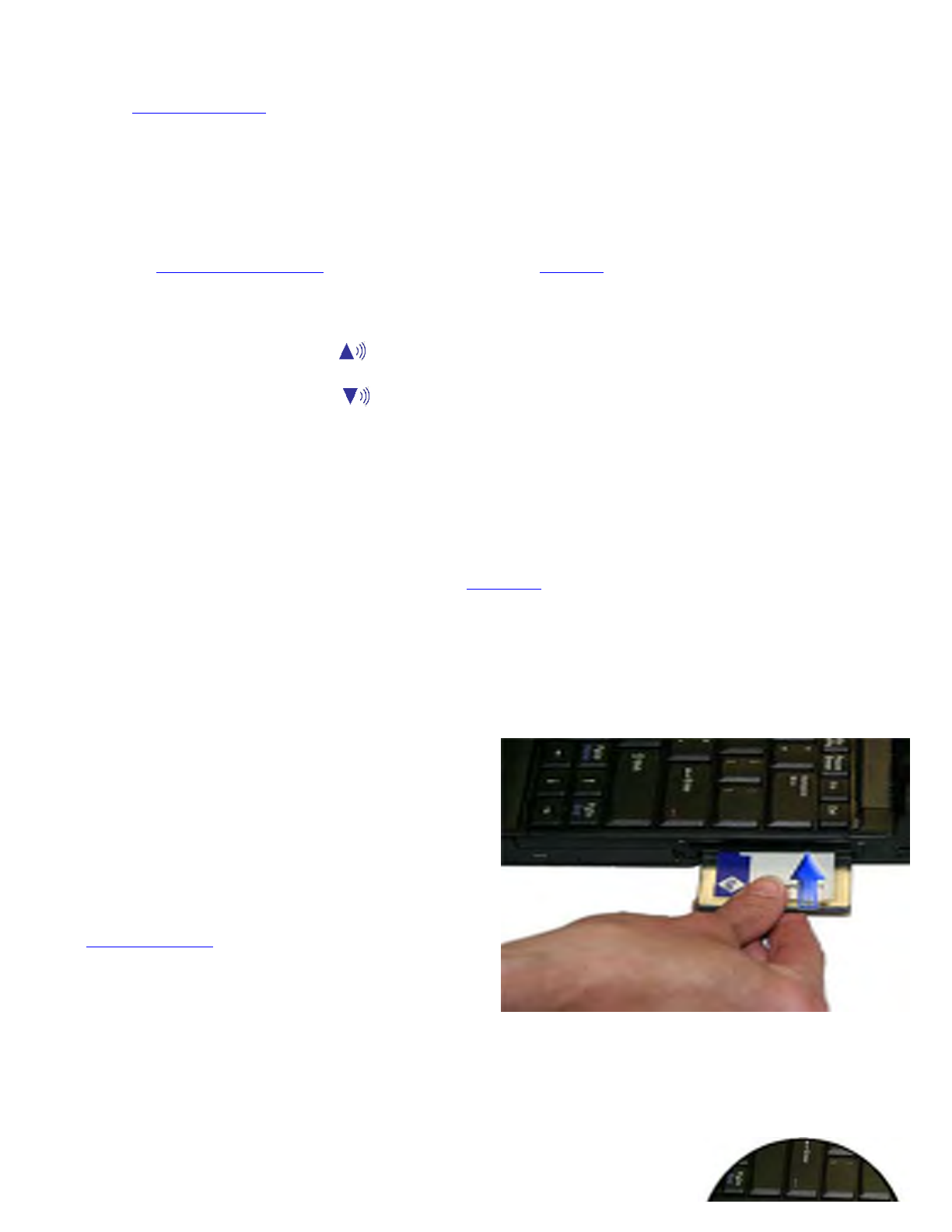
Ejecting a Card
Pa
g
e 21 of 70V
R
-2 Hel
p
4/26/2007file://C:\Documents and Settin
g
s\harwoodm\Local Settin
g
s\Tem
p
\~hh3F7F.htm

1. First, exit the application using the card.
2. Left-click on the Safely Remove Hardware icon on the taskbar and stop the card operation.
3. Press the slot eject button once to pop it out; then press it again to eject the PC Card.
Smart Card or EXPRESS Card Slot (option)
Your computer comes with a Smart Card Reader or EXPRESS Card slot (option). This slot is located directly above
the PC Card Slot on the Right Side of the computer.
To insert a card
Insert a card with the label side up into the slot until it clicks into place. The card now appears on My Computer as a
removable storage device that you can copy files to and from.
To remove a card
1. Make sure no operation (such as file copying or deletion) is using the card.
2. Press the card further into the slot to release the card. You will hear a click.
3. Remove the card.
Ports and Connectors
Media Storage
Your com
p
uter comes with the followin
g
media stora
g
e:
Ports and
Connectors Connection Location
RJ-11 Phone line/modem (internet and fax) Back Edge
RJ-45 Ethernet Back Edge
DC-in AC Adapter (power) Back Edge
2 USB 2.0 USB Peripherals such as a mouse,
printer or optical disk drive Back Edge
External Monitor External Monitor Back Edge
Audio In Microphone Left Side
Audio Out Speakers or headphones Left Side
PC Card Slot Type II PC Cards Right Side
Smart Card
Reader or
EXPRESS Card
Slot
Smart Cards or EXPRESS Cards Right Side
Security Slot Computer lock such as a Kensington
lock Left Side
Pa
g
e 22 of 70V
R
-2 Hel
p
4/26/2007file://C:\Documents and Settin
g
s\harwoodm\Local Settin
g
s\Tem
p
\~hh3F7F.htm
z High-capacity Enhanced-IDE removable hard disk drive
z Internal CDROM, DVD-ROM/CD-RW combo, or DVD-RW/CD-RW drive
z One Type II PC Card slot (option)
z One Express Card/54 slot OR One Smart Card slot (option)
The Hard Disk Drive
Your GoBook VR-2 features a removable hard disk to provide high-capacity storage and fast access. Windows and
most programs are stored here. Your GoBook VR-2 identifies the hard disk drive as drive C.
See the BIOS Setup Utility to password protect your removable hard disk drive.
Removing the Hard Disk Drive
1. Turn off the computer and turn it over so you
are looking at the bottom.
2. Using a Philips head screwdriver, remove the
screw next to the hard disk drive lock.
NOTE If you prefer quick hard disk drive
removal, do not reinstall this screw. It is an
additional locking feature.
3. Slide and hold the hard disk drive lock toward
the back of the computer to unlock the drive
.
4. Gently pull the drive out of the computer.
The Optical Disk Drive (option)
Your computer comes with a pre-installed CDROM,DVD-ROM/CD-RW , or DVD-RW/CD-RW combo drive. This
drive allows you to read data from DVDs and CDs, including audio or video CDs. If you have a RW drive you can,
and burn your data onto a CD recordable disc. If you have the DVD-RW/CD-RW drive, you can also burn data onto
a recordable DVD disc. Please refer to the recording software online help for more information.
Your notebook identifies the drive with the letter following the hard drive letter. If your hard drive is C, then the
optical disk drive will be D.
Inserting a Disk
1. Press the button on the front of the drive to
open the disk tray and pull the tray open.
2. Place the disk on the tray, label side up.
3. Place the disk on the central spindle and press
gently until the disk clicks into place.
4. Slide back the tray until it clicks shut.
Pa
g
e 23 of 70V
R
-2 Hel
p
4/26/2007file://C:\Documents and Settin
g
s\harwoodm\Local Settin
g
s\Tem
p
\~hh3F7F.htm

Removing a DVD or CD
1. Make sure the computer is not accessing the DVD drive.
2. Press the eject button and pull the tray all the way out.
3. Pick up the disk by the edges and remove it from the tray. Push the tray into the computer until it closes fully.
CAUTION When the computer is reading from a DVD or CD, the Optical Disk Drive LED will flash on. Do not
attempt to remove a disk while this light is active.
Precautions for Handling DVDs and CDs
Keep these precautions in mind when handling DVDs and CDs.
zAlways hold the disk by the edges; avoid touching the surface of the disk
zUse a clean, dry, cloth to remove dust, smudges, or fingerprints. Wipe from the center outward
zDo not write on the surface of the disk
zExtremes in temperature may damage disks. Store disks in a cool dry place
zDo not use benzene, thinners, or cleaners with detergent. Only use cleaning kits designed for DVDs or CDs
zDo not bend or drop the disks
zDo not place objects on top of disks
CAUTION Do not insert any foreign objects into the disk tray. Do not force the
tray to open or close manually. When not in use, keep the tray closed to prevent
dust or dirt from entering the drive unit. If you experience difficulty when
removing a disk, stretch a paper clip (or use a pin or a thin metal rod) and insert
it into the emergency eject hole located on the front panel (see picture).
The disk tray should eject immediately. This procedure can also be used to
remove a disk from the drive when the notebook is powered off.
PC Card Slot
See the PC Card Slot section for information.
EXPRESS Card or Smart Card Slot
See the EXPRESS Card and Smart Card Slot Section for information.
Computer Security
Your computer includes several different security features to help prevent theft and protect data. These include a
security slot, multiple levels of password protection, an optional fingerprint scanner, an optional Smart Card slot
and stealth mode.
Security Slot
Pa
g
e 24 of 70V
R
-2 Hel
p
4/26/2007file://C:\Documents and Settin
g
s\harwoodm\Local Settin
g
s\Tem
p
\~hh3F7F.htm

A security slot located on the left side of the computer lets you connect a
Kensington compatible computer security lock. You can connect the computer to an immovable object to prevent
theft. Insert the lock into the notch and turn the key to secure the lock. Some keyless models are also available. See
the documentation that comes with your lock for more information.
Passwords
Passwords protect your computer from unauthorized access. When set, no one can access the computer without
entering the correct password.
There are three types of passwords you can set:
zSupervisor Password secures your computer against unauthorized entry to critical parameters in the BIOS
Utility
zUser Password secures your computer against unauthorized use, and allows limited access to the BIOS
Utility
zHard Disk Password protects your data by preventing unauthorized access to your hard disk, even if the hard
disk is physically removed from the computer and installed in another computer
NOTE Do not forget your Setup and Hard Disk password! If you forget your password, please get in touch with
your dealer or an authorized service center.
Fingerprint Scanner (Option)
The optional swipe style fingerprint scanner can be used for all standard
security uses. The optional fingerprint scanner provides a greater level of
security and convenience for your GoBook VR-2 and your private data.
Use the fingerprint scanner instead of passwords for the following:
zduring computer login
zduring login at secure websites or when opening password protected
applications
zto provide encryption security for individual files
Fingerprint Scanner Software
Before using the fingerprint scanner, you must first install compatible software. There are various software packages
available
CAUTION Before installing any third party software, ensure it is approved for use with this computer.
NOTE When accessing some secure websites, you may need to specify you are using the scanner instead of a
p
assword. Refer to the fingerprint scanner software documentation for setup information.
Stealth Mode
Your computer has a stealth mode feature for users who may need to use it where light or sound could be dangerous
or disruptive, such as a military user. Enabling stealth mode allows you to disable sound and light features such as
system beeps, the fan, and the display backlight. Refer to the BIOS Setup Utility section for information about how
to confi
g
ure the stealth mode feature.
Pa
g
e 25 of 70V
R
-2 Hel
p
4/26/2007file://C:\Documents and Settin
g
s\harwoodm\Local Settin
g
s\Tem
p
\~hh3F7F.htm
Smart Card Reader (Option)
If your computer has the Smart Card Reader option, you can use smart card technology for added security.
Trusted Platform Module (TPM)
Enable or disable TPM in the System BIOS. TPM provides a platform root of trust which uniquely identifies a
p
articular platform and provides various crypto capabilities including hardware-protected storage.
Making Connections
Your computer is equipped with a full array of ports, connectors and bays, offering advanced communications
technology. This section describes how to connect peripherals and hardware options that help you maximize your
computer's features. Before connecting peripherals, first read the manual included with the peripheral for connection
and operation instructions. You can purchase most of these and other options directly from authorized dealers.
If you are a mobile worker, you may want to purchase one of the GoBook VR-2's docking solutions such as the
Vehicle Dock or Office Dock. These docks provide drop-in convenience, port expansion, and automatic battery
recharging, enabling you to leverage your computer's features without having to attach and reattach cables and
connectors when you move your computer from office to vehicle.
Attaching Power
Your GoBook VR-2 can be powered by battery, by attaching an AC Adapter or Vehicle Adapter to the DC power
p
ort, or by connecting the computer to a powered Vehicle Dock, or Office Dock. This page explains how to attach
p
ower to the DC power port.
NOTE When external power is properly applied, the External Power LED lights.
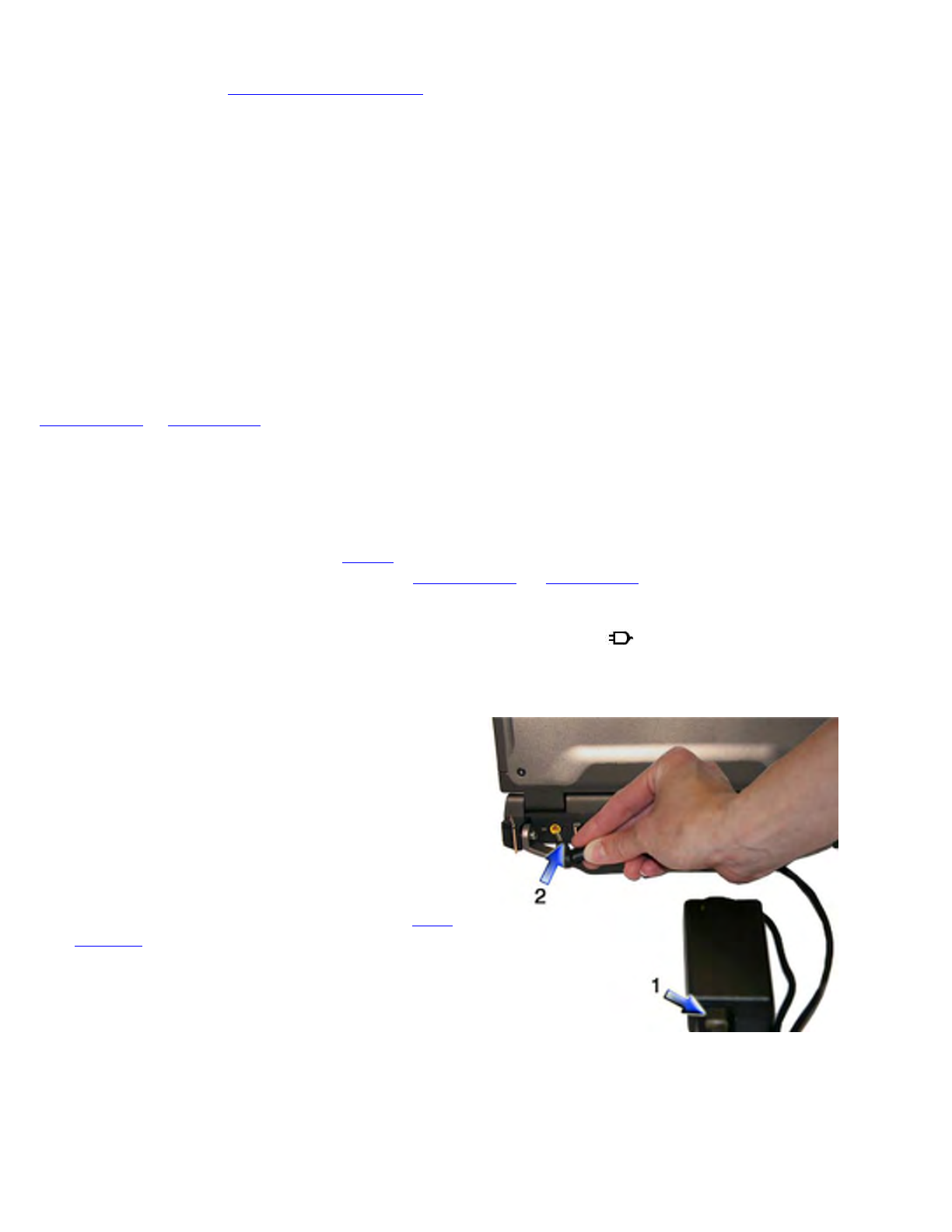
Using the AC Adapter
Using the Vehicle Adapter (optional)
1. Insert the vehicle adapter’s power cord into the DC-in jack on the back of the computer.
2. Insert the cigarette lighter adapter into the vehicle’s cigarette lighter socket, turning it slightly to make a good
connection.
1. Connect the AC adapter power cord to the AC
adapter.
2. Connect the AC adapter to the DC-in jack on the
back of your computer.
3. Connect the AC adapter power cord to a properly
grounded AC outlet.
NOTE It is recommended you use a quality surge
protector.
Pa
g
e 26 of 70V
R
-2 Hel
p
4/26/2007file://C:\Documents and Settin
g
s\harwoodm\Local Settin
g
s\Tem
p
\~hh3F7F.htm
CAUTION The vehicle adapter is not intended to be used continuously. It is intended to provide a
convenient, temporary power source for powering and charging this computer while in transit in a vehicle. For
permanent installations, it is recommended that the (fused) vehicle charger adapter be wired directly to the
vehicle power supply. For additional information with regard to permanent installation of the Vehicle
Adapter, contact your sales representative.
3. The power light illuminates to indicate that current is reaching the vehicle adapter. When you connect the
vehicle adapter, it automatically begins charging the computer’s battery. At moderate temperatures, around
21°C (70ºF), the battery should charge from empty to 90% in less than three hours if the unit is suspended or
off. It should take less than four hours if the unit is in use. However, under extremely cold or hot
temperatures, it will take longer to charge the battery (up to 16 hours).
CAUTION Avoid exposing batteries to extremely hot or cold temperatures for long periods. To prevent
possible damage to the battery, the GoBook VR-2 does not allow the battery to charge if the internal
temperature of the battery gets too low (< 5°C or < 41°F) or too high (> 50°C or > 122°F).
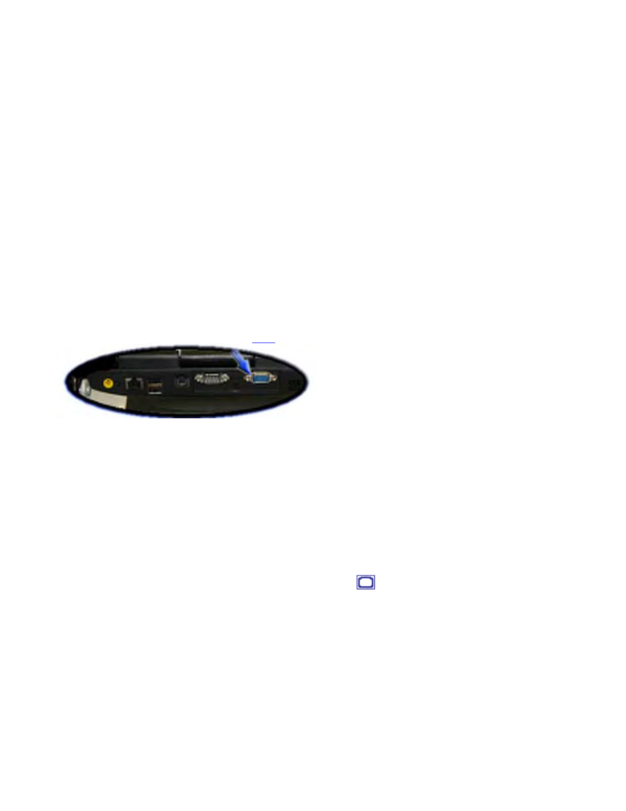
Attaching an External Monitor or Video Device
The notebook has a VGA monitor port to connect your computer to an external monitor. You may use an external
monitor simultaneously with your notebook's display, instead of your notebook's display, or as an extension of your
notebook's display. To attach an external monitor, perform the following:
1. Locate the external monitor port on the back of your notebook.
2. Connect the video signal cable from the external monitor (or the VGA adapter) to this port.
3. Connect the power cable from the external monitor to a power outlet and turn on the monitor.
Read the monitor manual for additional instructions.
Using Simultaneous Display
Your computer takes advantage of Windows dual-display capability, allowing you to use your computer for
p
resentation purposes. To use simultaneous display, connect an external display device to the external monitor port.
You can then toggle the display output location by pressing Fn+F2 . It will output to your computer's display, the
attached external display, or both displays simultaneously. Keep pressing Fn+F2 until you have the output option
you want.
Using Extended Display
When using an external monitor you can extend your desktop. This allows you to open and view one program on the
external monitor while viewing a different program on your laptop's display.
1. Right click on the desktop.
2. Select Properties to open the Display Properties Dialogue box.
3. Select the Settin
g
s tab.
Pa
g
e 27 of 70V
R
-2 Hel
p
4/26/2007file://C:\Documents and Settin
g
s\harwoodm\Local Settin
g
s\Tem
p
\~hh3F7F.htm
4. Click on the "2" in the Monitors section.
5. Check "Extend my Windows desktop onto this monitor".
6. Select Apply and OK to save and exit.
7. Now you can drag the programs you want to view onto the external monitor.
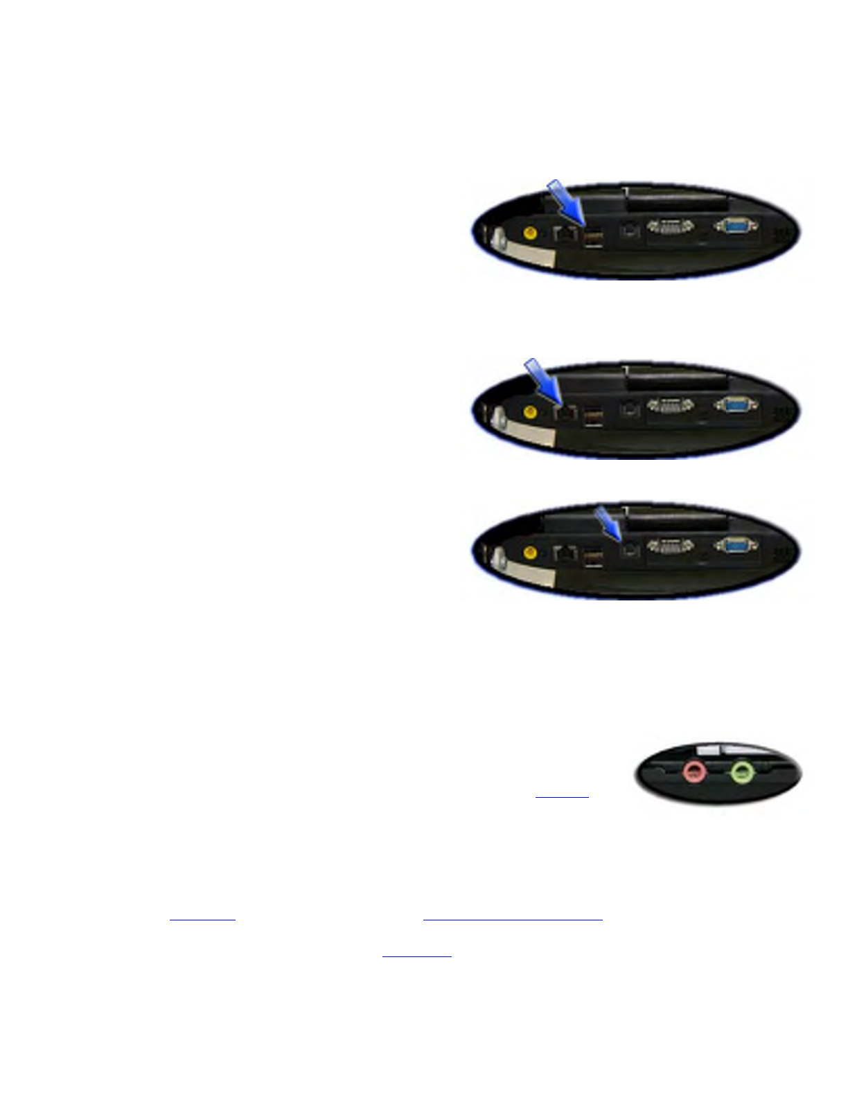
Attaching USB Devices
Your computer comes with two Universal Serial Bus (USB)
2.0 ports on the back of the computer. This enables you to
attach various devices such as a keyboard, mouse, scanners, or
p
rinter. USB devices can be chained together on a single cable.
Ethernet (LAN)
With the built-in Ethernet LAN, you can make LAN
connections with 10/100/1000 Mbps connection speed. To use
the network feature, connect an Ethernet cable from the
network jack on the rear of the computer to a network jack or hub on your network.
Fax/data modem
You can use the fax/modem to connect to the Internet to send
and receive data using the 56 Kbps V.90 protocol. When used
with fax software, it can be used as a fax at 14.4 Kbps. In some
countries, local regulations may not permit the use of the fax/modem designed for this system. In this case, you may
use a PC Card modem. To use the fax/data modem port, connect a phone cable from the modem port to a telephone
j
ack.
CAUTION Plug your modem into an analog telephone jack only. Most homes use analog lines. Do not use digital
lines, such as the PBX and ISDN systems found in many offices. Digital lines may damage your modem.
Attaching Audio Devices
Audio devices are easy to connect with the audio ports accessible from the left side of
the computer. You can plug an external microphone (or an audio line-in device) into the
line-in jack. Amplified speakers or headphones connect to the line-out jack.
External keyboard or pointing device
This computer has a keyboard with full-sized keys and an embedded numeric keypad. If you feel more comfortable
using a desktop keyboard, you can connect a USB external keyboard to one of the USB ports. You can also connect
a USB mouse or other pointing device to one of the USB ports.
Wireless Communication
Your GoBook VR-2 supports up to four integrated radios for superior wireless communication (One radio per
cate
g
or
y
listed below
)
.
Pa
g
e 28 of 70V
R
-2 Hel
p
4/26/2007file://C:\Documents and Settin
g
s\harwoodm\Local Settin
g
s\Tem
p
\~hh3F7F.htm

zWireless Local Area Network (WLAN)
zWireless Wide Area Network (WWAN) with CRMA Express
zGlobal Positioning System (GPS)
zBluetooth
Since each customer's radio configuration is unique, please read the radio help installed on your desktop and refer to
the manufacturer documentation to setup and use your radio(s).
Press Fn+Caps Lock to toggle the power on and off to all radio devices.
NOTE The radios do NOT function in suspend mode.
WLAN
Your computer comes with integrated Wireless Local Area Network (WLAN) capability.
About WLAN
WLAN provides all the features and benefits of traditional LAN technologies, such as Ethernet, without the
limitations of wires or cables. It enables mobility and flexibility without compromising connectivity for today's
mobile user.
CRMA Express WWAN (option)
If you ordered the CRMA Express module option, your computer may support one or more of these Wireless Wide
Area Network (WWAN) radios:
• EDGE/GPRS/GSM
• CDMA/1xEV-DO/1xRTT
• UMTS/GPRS/GSM
• HSDPA
• EVDO Rev A
CRMA Express upgradeable and when WWAN radio technology changes. You can change with it, giving you
greater wireless access when you need it.
About EDGE/GPRS/GSM Network
The Enhanced Data Rates for Global Evolution (EDGE) network allows users to transfer data with average speeds
of between 70 and 130 Kbps (kilobits per second) with burst speeds up to 200 Kbps. It is more than three times the
speed of GPRS. The EDGE network can help you perform at higher levels of productivity by providing real-time
wireless access to critical business systems and applications.
About CDMA/1xEV-DO/1xRTT Networ
k
Pa
g
e 29 of 70V
R
-2 Hel
p
4/26/2007file://C:\Documents and Settin
g
s\harwoodm\Local Settin
g
s\Tem
p
\~hh3F7F.htm

1xEV-DO
Evolution Data Only or Evolution Data Optimized (EV-DO) is a 3G wireless technology with average user
download speeds ranging from 400 to 700 Kbps with peak rates up to 2.0 Mbps. When you spend a lot of time away
from your desk, the faster speeds from EV-DO can lead to greater productivity. It's more than just fast email
retrieval. Get fast and secure access to your information and applications with EV-DO.
1XRTT - Single Carrier (1x) Radio Transmission Technology
1xRTT is a pre-3G wireless technology based on the CDMA platform. It has the capability to provide ISDN like
speeds of up to 144 Kbps with typical speeds in the 50-70 Kbps. 1xRTT is also referred to as CDMA2000.
About UMTS/GPRS/GSM Network
Universal Mobile Telecommunications System (UMTS), also referred to as wideband code division multiple access
(W–CDMA), is one of the most significant advances in the evolution of telecommunications into 3G networks.
UMTS is a worldwide standard for wide-area wireless data communication based on Global Systems for Mobile
communications (GSM™). UMTS provides broadband mobile access to business systems and applications that can
help improve mobile users' productivity.
UMTS provides broadband speeds with average data speeds of 220-320 Kbps and bursts up to 384 Kbps on some
networks. Its theoretical limit is 2 Mbps. It delivers four-to-six times the speed of dial-up Internet access and eight
times the speed of GPRS wireless data service. UMTS allows mobile users to respond to urgent emails and access
the Internet.
HSDPA
High-Speed Downlink Packet Access or High-Speed Downlink Protocol Access is a 3G GSM Mobile protocol in
the HSPA family, which provides a roadmap for UMTS-based networks to increase their data transfer speeds and
capacity. Current HSDPA deployments/cards/modules now support 1.8 Mbit/s, 3.6 Mbit/s, 7.2 Mbit/s and 14.4
Mbit/s in downlink.
EVDO Rev. A
EVDO Revision A (1x Evolution-Data Optimized) is a wireless radio broadband data standard that offers data rates
up to 2.4 mbps, Revision A integrates most of the faster data technology from 1xEV-DV Revision D, and improves
latency. These enhancements allow features such a VoIP and video calling.
GPS (option)
About GPS
The Global Positioning System (GPS) is a worldwide radio-navigation system formed from a constellation of 24
satellites and their ground stations. GPS uses these satellites as reference points to calculate positions accurate
within one meter.
Bluetooth (option)
About Bluetooth
Pa
g
e 30 of 70V
R
-2 Hel
p
4/26/2007file://C:\Documents and Settin
g
s\harwoodm\Local Settin
g
s\Tem
p
\~hh3F7F.htm
Bluetooth is a short range, wireless radio. When Bluetooth-capable devices come within range of one another, an
electronic conversation automatically takes place to determine whether they have data to share or whether one needs
to control the other. Then, the devices hop frequencies in unison so they stay in touch with one another and avoid
interference with other devices. Bluetooth devices send out very weak signals of 1 milliwatt. By comparison, the
most powerful cell phones can transmit a signal of 3 watts. This limits their range to about ten meters. Even with the
low power, the walls in your house won't stop a Bluetooth signal, making the standard useful for controlling several
devices in different rooms.
Antennas
The GoBook VR-2 has several embedded antenna options to support wireless communications.
Improving Radio Coverage
Wireless connectivity between your GoBook VR-2 and wireless network access points is essential. Maintaining this
wireless connectivity over a wide area is fundamental to the usefulness of the network. This makes the scope and
reliability of radio coverage a primary concern. Therefore, one of the most important features of the wireless
network is the degree of radio coverage provided. Coverage can be influenced by terrain, buildings or even a
crowded room. Here are some tips to help you improve radio coverage, depending on your location.
In any Location
1. Performance can vary significantly at different times of the day.
2. Weather can affect performance.
On the Street
# Antenna
1 CRMA Express Antenna
2 GPS Antenna
3 WLAN Antennas
4 Bluetooth / Diversity Antenna
Pa
g
e 31 of 70V
R
-2 Hel
p
4/26/2007file://C:\Documents and Settin
g
s\harwoodm\Local Settin
g
s\Tem
p
\~hh3F7F.htm

1. Try all sides of a building to see which side provides the strongest radio signal.
2. Move from under trees. Pine needles absorb radio signals more than leaves.
3. Move away from overhead electrical wires.
4. Radio signals reflect off other buildings. Even in the signal shadow, the signal could be reflected back by
another building.
5. Try not to hold the unit. If possible, place it in vehicle, on a cabinet or desk.
6. If holding the unit, turn the unit in 90-degree increments to avoid shielding it with your body.
7. The signal is 1-2 feet across; therefore, moving several feet in any direction may give different results.
Inside a Building
1. Move toward windows.
2. Signals do not penetrate ground; therefore, there will probably be no signal in basements.
3. Reflective coatings on windows reflect radio signals. Try the side of the building that is least likely to have
coated windows.
4. Closed metal blinds can reflect radio signals.
5. Dropped ceilings sometimes hide an accumulation of electrical cable.
Electromagnetic Interference (EMI)
1. Electromagnetic Interference (EMI) is generated by switching circuitry closets or Un-interruptable Power
Source (UPS) systems found near computer rooms and can block the radio signal.
2. Look for significant sources of electromagnetic radiation. The problem may emanate from a source between
location and the radio base station.
When to use Landline Communication
If these tips do not improve radio signal strength, switch to landline communication. Switching to landline
communication is faster than searching for and trying to improve the radio signal.
Operating with Battery Power
The computer operates on AC or battery power. This section contains the information you need to know to operate
the computer on battery power. It also includes information on how your computer manages and saves power.
Battery pack
The battery pack has the following characteristics:
zEmploys current battery technology standards
The com
p
uter uses a "smart" Lithium-Ion batter
y
to consistentl
y
p
rovide the lon
g
batter
y
life best suited for
Pa
g
e 32 of 70V
R
-2 Hel
p
4/26/2007file://C:\Documents and Settin
g
s\harwoodm\Local Settin
g
s\Tem
p
\~hh3F7F.htm

mobile users
zA temperature sensor and memory device that stores information about the battery, such as how much charge
is left and how many times it has been recharged
zBattery-low warning
When the battery charge level becomes low, the battery alarm beeps or displays a warning on your screen.
This tells you that the battery power is critically low (and you should save your work). You can correct this
situation by recharging the battery pack.
Whenever possible, use the AC adapter. The battery will come in handy when you travel or do not have access to
AC power. It is advisable to have an extra fully-charged battery pack available as backup.
Using a battery pack for the first time
Before using a battery pack for the first time:
1. Connect the AC adapter to the computer, then to a power source.
2. Calibrate the battery to set the gas gauge to accurately reflect battery capacity.
You only need to do this once with a new battery or with a battery that's been stored without being used for a
long time. If the computer is to be stored for more than two weeks, we recommend you remove the battery
pack.
Battery and Temperature
The battery is most efficient at room temperature. It operates in a wide temperature range but the battery capacity is
affected by higher or lower temperatures.
WARNING Do not expose battery packs to temperatures below 0ºC (32ºF) or above 46ºC (115ºF). This may
adversely affect the battery pack.
Installing and removing the battery pack
CAUTION! Before removing the battery pack, make sure that you have an AC adapter connected to the computer;
otherwise, turn off the computer.
To install a battery pack:
Temperature Approximate
Capacity
0°C 80%
20°C 100%
45°C 100%
1. Line up the battery connectors.
2. Press gently on the battery until it
clicks into place.
Pa
g
e 33 of 70V
R
-2 Hel
p
4/26/2007file://C:\Documents and Settin
g
s\harwoodm\Local Settin
g
s\Tem
p
\~hh3F7F.htm
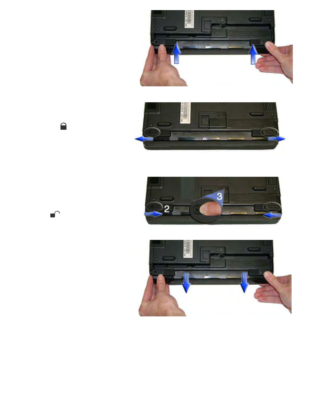
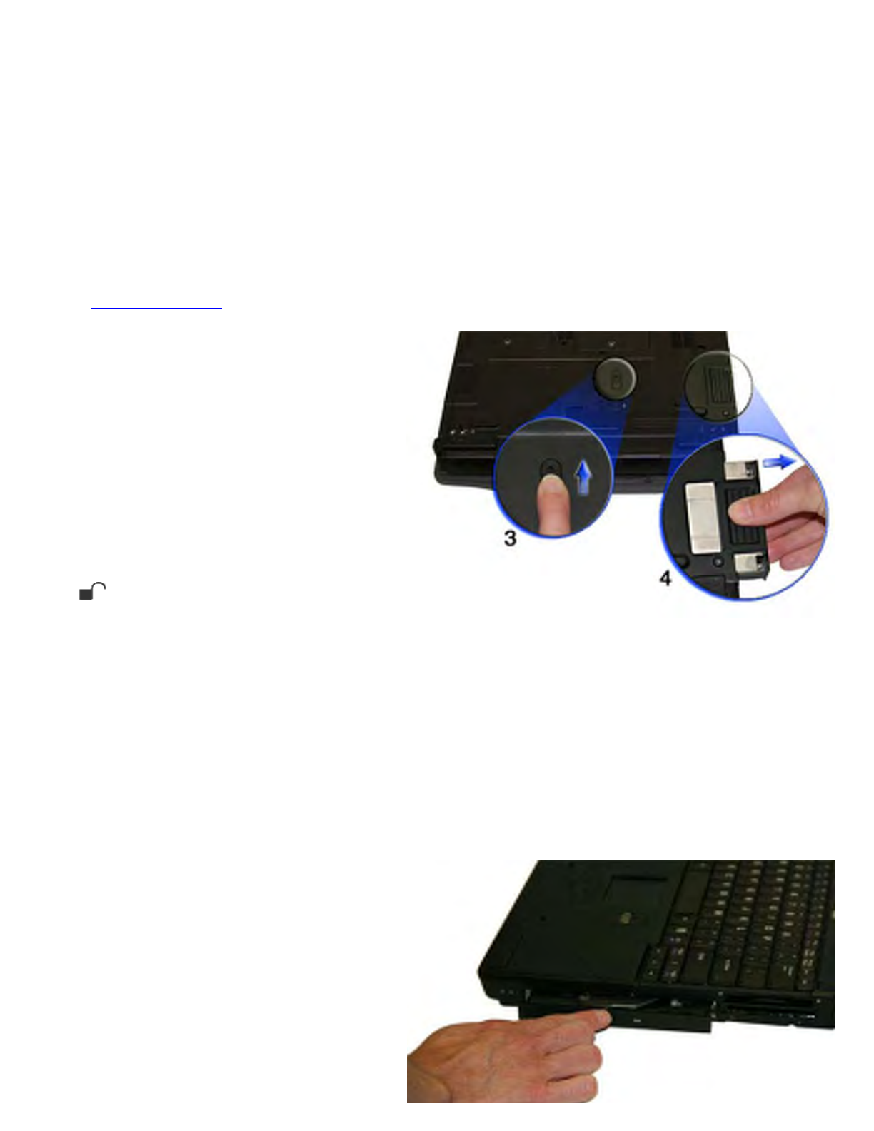
To remove the battery pack:
Battery Calibration
Over time, as the battery is repeatedly drained and recharged, battery performance will decrease. The first time you
use the battery, you should calibrate it. Occasionally, the battery needs to be recalibrated for maximum performance.
The calibration process empties and charges the battery. This allows the Windows battery gauge to accurately
monitor battery status.
It is recommended
y
ou calibrate
y
our batter
y
:
3. Slide the battery locks toward the
outside of the computer to lock the
battery and ensure they latch
completely .
1. Plug in AC power and turn off the
computer.
2. Slide the battery locks toward the
inside of the computer to unlock the
battery .
3. Slide and hold the battery release
latch.
4. Gently slide the battery out of the
computer.
Pa
g
e 34 of 70V
R
-2 Hel
p
4/26/2007file://C:\Documents and Settin
g
s\harwoodm\Local Settin
g
s\Tem
p
\~hh3F7F.htm

zThe first time you use your computer
zAfter it has been stored for awhile
zIf the gas gauge has become inaccurate.
zEvery three months for optimum performance
Windows Battery Calibration
To run the Battery Calibration program select Start, All Programs, and Mobile Computer Tools. Next, select
Battery Calibration. After starting calibration, the Battery Calibration application requires no further input from
the user. The calibration consists of four steps:
1. Partial Discharge - the battery is drained to a level below 90 %.
2. Charge - the battery is fully charged to 100 %.
3. Discharge and calibrate:
First, the battery is discharged all the way down to zero. Now the battery is 'calibrated' but not charged. You
may stop the process after this point and let the battery charge outside of the Battery Calibration application.
4. Charge - if the Battery Calibration continues running, the battery will fully charge to 100%.
Battery Calibration will take from 5 to 10 hours, depending on how much power the battery may already
contain.
NOTE The unit will not go into suspend mode while Battery Calibration is running.
CAUTION Do not disconnect AC power while Battery Calibration is running. If AC remains disconnected for
more than two minutes, the application will terminate.
CAUTION Do not remove the battery while Battery Calibration is running. Doing so will cause the application to
terminate immediately.
Battery Charging
To charge the battery, install the battery pack and plug the AC adapter into the computer and an electrical outlet.
You can use your computer while charging the battery. However, this will increase the charging time.
NOTE We suggest that you charge the battery pack before retiring for the day and let it charge overnight before
traveling. This ensures a fully charged battery for use the next day.
While the battery is charging, the Battery Power LED will be active after 6-12 seconds and will stay lit until the
battery is fully charged. When the battery is fully charged, the Battery Power LED will turn off.
If your computer is turned off, a fully discharged battery will take about 3 hours to recharge. If your computer is
turned on and is not in suspend mode, it will take about 3-6 hours to recharge the battery. Refer to the following
table:
Charging Discharging
System On 3-6 hours depending
on temperature and
processes running
3.5 hours
System Off 3 hours
Pa
g
e 35 of 70V
R
-2 Hel
p
4/26/2007file://C:\Documents and Settin
g
s\harwoodm\Local Settin
g
s\Tem
p
\~hh3F7F.htm

NOTE A fully charged Li-Ion battery can run the Notebook for approximately 3.5 hours of normal use. (According
to an industry standard bench marking tool). Use of external devices, the optical disk drive and wireless radio
causes increased battery consumption. Refer to the Battery Tips section for ideas to conserve battery power.
When to Replace the Battery
Over time, the battery’s capacity gradually decreases. We recommend that you replace your battery when you notice
that it begins to store significantly less charge. See Battery Installation and Removal for more information.
Heat Considerations
The computer’s processor has been specially designed to consume as little power as possible, and generates very
little heat. However, working in a hot environment, or working for long periods may raise the temperature. The
GoBook VR-2 takes the following steps to lower temperature:
1. The cooling fan turns on automatically. You may feel air coming from a vent at the left side of the computer
when this happens.
2. If the temperature continues to rise, processor activity will be reduced. You may notice a slight loss of
performance when this happens.
WARNING If the CPU temperature exceeds 95°C, the system will shutdown to prevent the heat from damaging
the computer's infrastructure. When the computer cools to a normal temperature you can restart the system. The
higher the temperature, the longer the period the computer will need to cool down.
Monitoring Battery Power
To see how much power the battery has left, move the cursor to the Power Saver icon ( or ) in the System
Tray area of the Taskbar. The status will show as a pop-up when you mouse-over the icon.
Low Battery Alarms
How your computer responds to a low battery condition can be set by going to Start, Settings, Control Panel,
Power Options, Alarms.
Two different power alarms can be enabled or disabled: the Low Battery Alarm, and the Critical Battery Alarm.
Use the slide bar to set the power level at which the alarms are activated. Select the Action button to choose
whether the alarm sounds, displays a message, or both.
CAUTION When battery power is low, the alarm beeps or displays a warning on your screen. Take immediate
action, such as saving files or connecting to the AC adapter , or data may be lost.
When the computer alerts you that the battery is low, immediately do one of the following:
zConnect the AC power adapter
zSave
y
our work and then select Shut Down from the Start menu
Suspend to
RAM 72 hours
Suspend to Disk 7 days
Pa
g
e 36 of 70V
R
-2 Hel
p
4/26/2007file://C:\Documents and Settin
g
s\harwoodm\Local Settin
g
s\Tem
p
\~hh3F7F.htm
Turn off the computer and replace the discharged battery with a charged battery (See Battery Charging).
NOTE Do not restart the computer until you have connected to an AC adapter or replaced the discharged battery
with a charged battery.
Refer to Battery Tips for more information about how you can conserve battery power. Refer to Managing Power
for information about how you can setup your computer to effectively manage power for your unique use patterns.
Managing Power
Your computer has power management capability so you can reduce the amount of energy used, especially during
p
eriods of inactivity. Effective use of power management options can greatly conserve and extend your battery life.
The power management unit monitors system activity, such as hard drive, keyboard, mouse, or any devices attached
to a port. If it does not detect activity for a period of time, the computer stops some or all of these devices in order to
conserve energy.
Your computer employs a power management scheme that supports ACPI (Advanced Configuration and Power
Interface), allowing for maximum power conservation and maximum performance at the same time. Windows
handles all power-saving chores for your computer.
For more information search for Power Options in Microsoft (R) Help and Support.
Power Saver
Your computer includes a utility, the Power Saver, that builds upon the operating system's power management
capabilities. It is recommended that you use Power Saver rather than the Power Management utility located under
the Control Panel. Power Saver provides additional ways of saving battery power.
When on external power, Power Saver provides two profiles: Faster Charge and Normal. When on battery, it
p
rovides another two profiles: Max Life and Normal. You can easily toggle between the Max Life and Normal
battery profiles by pressing Ctrl+Space.
There is also an option to keep the computer awake, while at the same time, saving battery power.
To Set the Power Saver Mode
1. On the System Tray area of the
Taskbar, right-click the Power Saver
icon (see table).
2. Select the desired power profile.
NOTE You can easily see which
profile you are currently using by the
color of the Power Saver icon (see
table).
To Configure Power Saver Settings
1. On the System Tray area of the
Taskbar, right-click the Power Saver
icon.
2. From the menu, select Configure
Power Settings.
Power Saver Icons
Icon Description Icon Description
The computer is on
battery power and set
to use the Max Life
battery profile.
The computer is on
external power and
set to use the Faster
Charge plugged in
profile.
The computer is on
battery power and set
to use the Normal
battery profile.
The computer is on
external power and
set to use the Normal
plugged in profile.
The computer is on
battery power and set
to Stay Awake.
This setting:
zoverrides any
settings that
cause the
The computer is on
external power and
set to Stay Awake.
This setting:
zoverrides
settings that
cause the
Pa
g
e 37 of 70V
R
-2 Hel
p
4/26/2007file://C:\Documents and Settin
g
s\harwoodm\Local Settin
g
s\Tem
p
\~hh3F7F.htm

Low-Power States
Your computer can enter three different low-power states to conserve power: Standby, Hibernate and Power Off.
These states can be entered manually, or after a period of inactivity. You can configure the Power Saver utility to
define how and when each of these occur.
Standby
Most devices in the system are powered off, but the contents of system memory are retained. Standby is sometimes
referred to as Suspend to RAM. When the computer returns from standby mode, the desktop appears with the same
files and programs open as when the computer was suspended. Resume time is very quick.
Hibernate
Hibernate, or Suspend to Disk, is similar to Standby, except that the current state of the computer is copied to the
hard disk in a special file. After this occurs, all devices in the computer are turned off. When the computer returns
from hibernation, the desktop appears with the same files and programs open as when the computer was suspended.
Hibernation saves more power than Standby, but takes slightly longer to resume.
Power Off
All applications are closed and the system is shutdown.
Entering Low-Power States
There are various ways to initiate these low-power states.
• From the Power Saver utility, you can configure the Power Button, Sleep Button (FN+F3) and Lid Switch to
initiate any of the above low-power states.
• From the Start Menu, select Shut Down to display a dialog that allows you to manually enter any of these low-
p
ower states.
• The Power Saver utility allows you to specify a period of inactivity before the computer enters standby or
hibernate mode.
3. Change settings as desired. computer to
inactivity
suspend,
hibernate or
turn off the
display.
zmay shorten
your battery life
and should only
be used
temporarily.
zis automatically
reset if the
computer is
shut down or
restarted.
computer to
inactivity
suspend,
hibernate or
turn off the
display.
zis
automatically
reset if the
computer is
shut down or
restarted.
Pa
g
e 38 of 70V
R
-2 Hel
p
4/26/2007file://C:\Documents and Settin
g
s\harwoodm\Local Settin
g
s\Tem
p
\~hh3F7F.htm

Battery Tips
Tip 1. Avoid excessive heat and cold
zYour battery will last longer during the day if it is used, charged and stored between 50°F and 86°F (10°C and
30°C)
zCharge the battery nightly where the temperature will remain around 68°F (20°C). Your battery may not last
as long through the day if you charge it at higher or lower temperatures
zAllow unrestricted airflow while the computer is connected to external power. Make sure that the fan inlet and
outlet are unobstructed
zAvoid exposing batteries to hot or cold temperatures for long periods
How your battery behaves in warm conditions
How your battery behaves in cold conditions
Tip 2. Prevent wasted power
zManually turn off or suspend your computer whenever you are not using it
zReduce the screen brightness. Decrease brightness by pressing FN+F6. Increase it by pressing FN+F7
NOTE You can select a maximum brightness setting in the Power Saver utility
zUse the AC adapter or vehicle adapter whenever possible
zUse the Power Saver utility to configure your computer for optimal power savings
NOTE It is recommended that you use Power Saver rather than the Power Management utility located under
the Control Panel. Power Saver provides additional ways to save battery power.
To Adjust Power Saver Settings
1. On the System Tray area of the Taskbar, right-click the Power Saver icon ( or ).
2. From the menu, select Configure Power Settings. This opens the Power Saver utility, enabling you to
configure your computer for optimal power savings. See Managing Power for more information.
zWhen running on battery power, use the Power Saver utility to make sure your system suspends automatically
after a few minutes of inactivity. PC Cards, radios, custom applications, or modified system settings may
affect this
zRemove PC Cards or disable them in Power Saver. Unplug peripherals when you are not using them. They
may draw power from the system even when not in use
zAvoid operating the fax/modem, or audio and video applications when using battery power. Operating a
fax/modem, video, or audio equipment increases the computer’s power requirements
zDon't use screen savers as they draw excessive current, especially “3D” screen savers
zTurn off the Wireless LAN when not using it. Turning on the Wireless LAN increases the computer's power
re
q
uirements
Pa
g
e 39 of 70V
R
-2 Hel
p
4/26/2007file://C:\Documents and Settin
g
s\harwoodm\Local Settin
g
s\Tem
p
\~hh3F7F.htm

zAvoid or minimize using applications that keep the CPU busy a large percentage of the time. The following
will help you determine if your system is running such applications:
Identifying power wasting programs
What to do if applications are keeping the CPU busy
Tip 3. Calibrate your battery
zOver time, the accuracy of the Windows battery gas gauge may be affected by repeated charging and
discharging of the battery. Calibrating the battery every three or four months helps to keep the gas gauge
accurate. For information on calibrating the battery, refer to Battery Calibration
Tip 4. Get a good charge
zYour computer will charge more quickly if it is turned off or suspended
zIn warmer or cooler temperatures, your battery can take much longer to fully charge
zIf your battery is charged in a cold (less than 41°F/5°C) or very warm (greater than 122°F/50°C) environment,
it is possible that the Battery Charge LED will indicate that the charge has stopped; however, this does not
necessarily mean that your battery is fully charged
Tip 5. Prevent data loss
Follow these guidelines to prevent data loss when removing your battery or storing your computer:
zYou will lose data if you remove the battery while the computer is operating or suspended. To prevent this,
shutdown your computer or put it into hibernate (suspend-to-disk) mode before removing your battery
zIf you plan to store your computer for more than a few days, shutdown your computer or put it into hibernate
mode. Remove the battery before storing the computer
Tip 6. Clean terminals
zDirty terminals can be a cause of charging problems. Clean battery terminals with a cotton swab dipped in
isopropyl alcohol. Make sure that the alcohol has evaporated before reinstalling the battery
Tip 7. Storing batteries
zStore the battery within the recommended temperature range: 10°C to 30°C (50°F to 86°F)
zUnused or stored batteries can lose power over time. When you install a battery that has not been used for
awhile, connect external power to the computer and fully charge your battery
zBattery calibration may increase the capacity of a battery stored for a period of time. For information on
calibrating the battery, refer to Battery Calibration
zIt is recommended that the battery is recharged every six months while in storage
Customizing Your BIOS Settings
This section ex
p
lains how to use the BIOS Setu
p
Utilit
y
to modif
y
the BIOS settin
g
s. The Setu
p
Utilit
y
dis
p
la
y
s and
Pa
g
e 40 of 70V
R
-2 Hel
p
4/26/2007file://C:\Documents and Settin
g
s\harwoodm\Local Settin
g
s\Tem
p
\~hh3F7F.htm

allows modification of the computer's components and allows you to configure devices that are connected to it. This
information is used to test and initialize components during boot up and to make sure everything runs properly when
the system is operating.
Your computer is already properly configured and optimized with a set of default values so you do not need to run
this utility. In certain circumstances, the system may generate an error message that asks you to make changes to the
BIOS settings using the Setup Utility. This happens if the system finds an error during the POST (Power On Self
Test) that it carries out at start-up. Please first refer to Troubleshooting if a problem arises.
If you are not sure how to configure the BIOS settings we suggest that you select "Load Optimal Defaults" on the
Exit Menu screen, then exit saving changes. This loads optimized default settings for normal use.
The most commonly used Setup functions are:
zSetting the date and time
zSetting a password
zBoot order setup
zStealth mode setup
Using the Setup Utility
The Setup Utility allows you to configure your computer’s basic settings. When you turn your computer on, the
system reads this information to initialize the hardware so that it can operate correctly. You can use the Setup Utility
to change your computer’s start-up configuration. For example, you can change your system's security settings.
Starting the Setup Utility
You can only start the Setup Utility after the computer has been turned on or rebooted. To execute a controlled
reboot, select Start, Shutdown, Restart. Shortly after the computer restarts, you will see the following text at the
bottom of the screen: "Press F2 to enter Setup."
Press the F2 key when you see this prompt.
NOTES
The BIOS password settings affect this option. If a user or supervisor password has been previously
entered, you will be asked for a password.
The touch screen is not active in the Setup Utility.
Navigation
Hover the mouse over each numbered call out and each menu bar item on the picture to see a description.
Pa
g
e 41 of 70V
R
-2 Hel
p
4/26/2007file://C:\Documents and Settin
g
s\harwoodm\Local Settin
g
s\Tem
p
\~hh3F7F.htm
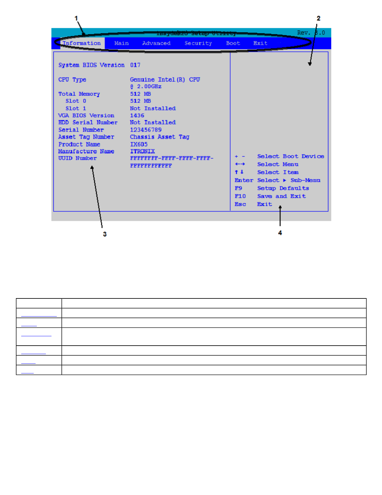
The Menu Bar
The Setup Utility has six menu options in the Menu Bar (1) at the top of the window. Press the left or right arrow
keys to cycle through these menu screens.
The Field Help Window
The Field Help Window (2) is on the right side of each menu. It displays the help text for the currently selected
field. This text updates as you move the cursor from field to field.
Viewing or Changing Field Settings
The Navigation Help instructions (4) also on the right side of each menu displays the keys used to move through and
change the Settings and Information fields (3) on the left side of the menu.
zPress the u
p
and down arrow ke
y
s to c
y
cle throu
g
h fields on each menu
Menu Description
Information Displays a summary of the computer's hardware information
Main Contains basic settings about your computer such as date, time, and other general options
Advanced Allows you to view and configure your drives, and I/O (input/ output) ports, and stealth mode
settings
Security Lets you set passwords for protecting your computer
Boot Allows you to set the order in which the system boots up
Exit Includes options to save or discard your changes, and to exit the BIOS Utility
Pa
g
e 42 of 70V
R
-2 Hel
p
4/26/2007file://C:\Documents and Settin
g
s\harwoodm\Local Settin
g
s\Tem
p
\~hh3F7F.htm
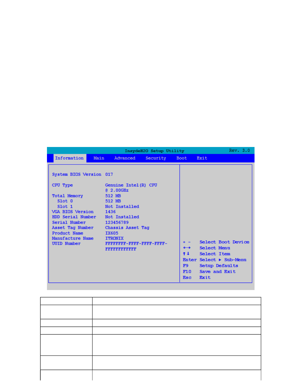
zPress Esc to exit any sub-menu
zPress Enter to make a selection or go into a sub-menu
NOTE You can change the value of a field if it is enclosed in <brackets>. Navigation keys for a menu are shown at
the bottom of the screen. Please refer to the help information that displays in the Field Help Window as you select a
field.
CAUTION Certain fields are highly technical. Do not make changes to a field if you do not understand its
function. For optimum settings, press F9 to load setup defaults; then press F10 to save the changes and exit the
Setup Utility.
NOTE Don't forget your password. If you forget your password, you may have to return your notebook computer
to your dealer to reset it.
The Information Menu
This page displays information about your computer from what kind of CPU and how much memory the computer
has, to pertinent numbers such as the product number and serial number:
Field Description
System BIOS
Version Displays the current system BIOS version
CPU Type Displays the CPU information
Total Memory Displays the current system memory
Slot 0
Slot 1
Displays the current amount of memory in each memory card slot
VGA BIOS
Version Displays the current VGA BIOS version
HDD Serial Displays the primary master HDD serial number
Pa
g
e 43 of 70V
R
-2 Hel
p
4/26/2007file://C:\Documents and Settin
g
s\harwoodm\Local Settin
g
s\Tem
p
\~hh3F7F.htm
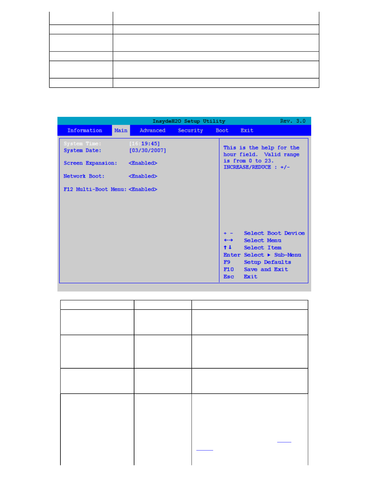
The Main Menu
Number If there is no primary master HDD, "Not Installed" displays
Serial Number Displays the System Serial Number (30 characters)
Asset Tag
Number Displays the Asset Tag Number (32 characters)
Product Name Displays the Product Name (up to 15 characters). This is "IX605"
Manufacturer
Name Displays the Manufacturer Name (up to 15 characters).
UUID Display the UUID (16 Byte Hex-Digital)
Field Setting Function
System Time HH:MM:SS Sets the system time in 24 hour
format. The value takes effect
immediately
System Date MM/DD/YYYY Sets the system date. The date can
be set from January 1, 2000 to
December 31, 2099. The value takes
effect immediately
Screen Expansion Enabled
Disabled When enabled, the computer will
allow a low resolution image to fill
the display
Network Boot Enabled
Disabled When enabled, the system can boot
from the network. This setting
requires a reboot to take effect
NOTE The LAN must be selected
as the first boot item on the Boot
Menu for the computer to boot
directly from the network during
Pa
g
e 44 of 70V
R
-2 Hel
p
4/26/2007file://C:\Documents and Settin
g
s\harwoodm\Local Settin
g
s\Tem
p
\~hh3F7F.htm
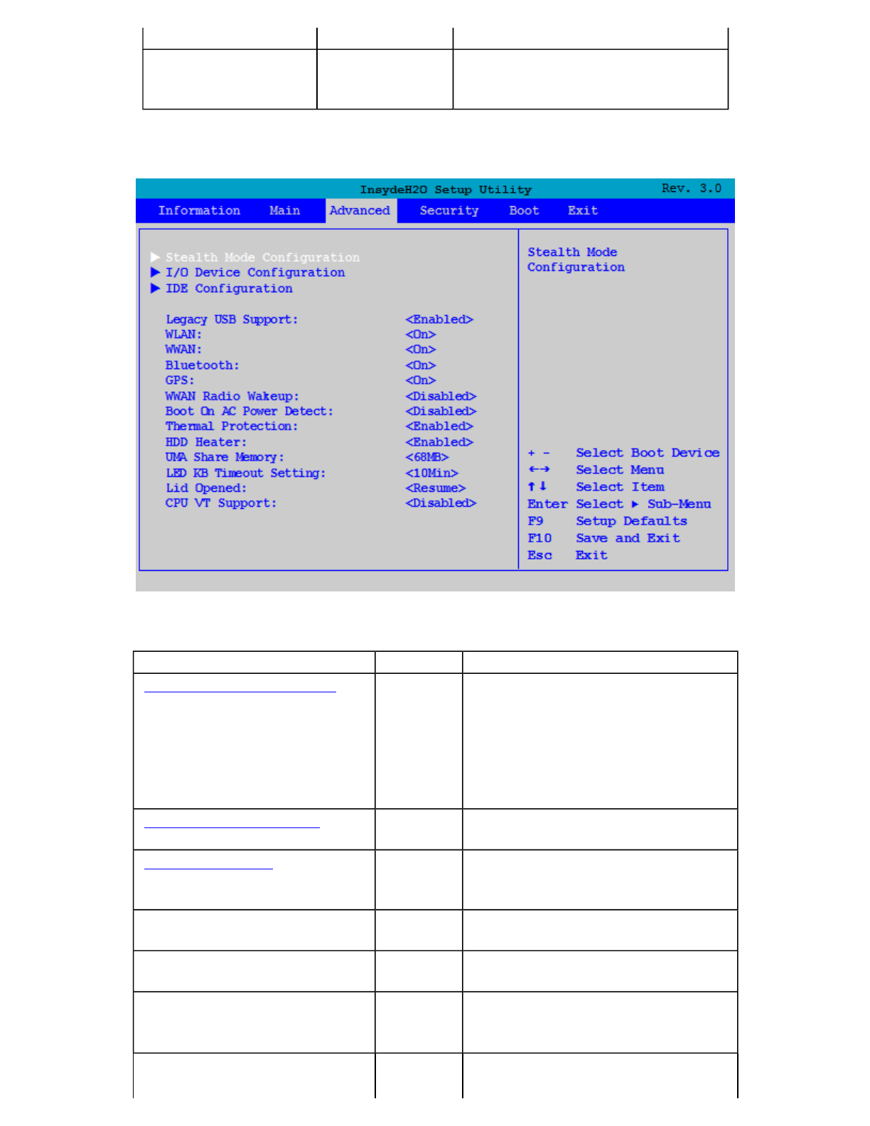
The Advanced Menu
power on
F12 Multi-Boot Menu Enabled
Disabled When enabled, the message "F12 to
enter Multi Boot Menu" displays
during POST
Field Setting Function
Stealth Mode Configuration sub-
menu Configuring the stealth mode feature
enables you to turn off sound and
light such as the fan, beeps, and the
backlight. This allows you to use the
computer in an environment where
sound and light could be dangerous
or disruptive
I/O Device Configuration sub-
menu Configure I/O Devices (serial and
parallel ports)
IDE Configuration sub-
menu Selects the IDE controller and hard
disk drive type installed in your
system
Legacy USB Support Disabled
Enabled When enabled, the system can
support legacy USB devices
WLAN Off
On Wireless LAN devices are powered
on or off when the system reboots
WWAN Off
On
Wireless WAN devices are powered
on or off when the system reboots
Bluetooth Off Bluetooth devices are powered on or
off when the system reboots
Pa
g
e 45 of 70V
R
-2 Hel
p
4/26/2007file://C:\Documents and Settin
g
s\harwoodm\Local Settin
g
s\Tem
p
\~hh3F7F.htm

On
GPS Off
On
GPS devices are powered on or off
when the system reboots
WWAN Radio Wakeup Disabled
Enabled This option determines the WWAN
radio power when the system is
suspended.
When disabled, radio power is
turned off before system enters
standby state.
When enabled, the radio power
remains on when the system is in
standby
Boot On AC Power Detect Disabled
Enabled If enabled, the system detects when
AC power is connected and boots up
or resumes automatically
Thermal Protection Disabled
Enabled If enabled, the system can NOT boot
up in temperatures between 0 and -
20 C°. If disabled, the system can
boot up outside this temperature
range
CAUTION disabling thermal
protection may result in damage to
the unit and void the warranty
agreement
HDD Heater Disabled
Enabled If enabled, the system is warmed by
an HDD Heater
UMA Share Memory 64MB
128MB The size of the main memory that is
allocated to support the Internal
Graphics device in VGA graphics
mode
LED Keyboard Timeout Setting 5Min
10Min
15Min
20Min
30Min
40Min
50Min
60Min
80Min
100Min
120Min
240Min
Choose the interval at which the
timeout counter is reset for PS2 key
and/or mouse activities. The
Keyboard task lights will turn off
after the set period of inactivity
Lid Opened Nothing
Resume If set to "Nothing" there is no action
taken when the Lid is opened
If set to "Resume", the system will
resume from a suspended state when
the lid is opened
CPU VT Support Disabled
Enabled If enabled, performance is increased
for server systems.
Note: System Security may be
affected if this setting is enabled.
Pa
g
e 46 of 70V
R
-2 Hel
p
4/26/2007file://C:\Documents and Settin
g
s\harwoodm\Local Settin
g
s\Tem
p
\~hh3F7F.htm
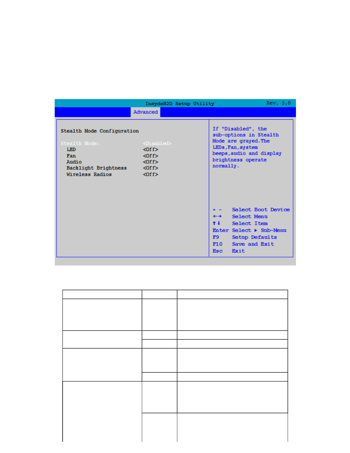
Stealth Mode Configuration
Stealth mode is a feature that allows the computer to be used in an environment where sound and light could be
dangerous or disruptive. If stealth mode is disabled, the LEDs, fan, system beeps, audio, and display brightness
operate normally.
NOTE An off setting indicates stealth mode is in effect for that option. For example, if stealth mode is enabled and
the LED option is set to "off", the LEDs will NOT illuminate to indicate activity.
Field Setting Function
Stealth Mode Disabled
Enabled Enable or disable stealth mode. If
disabled, the computer functions
normally and the options listed
below are not accessible.
LED Off LEDs are disabled
On LEDs function normally
Fan Off The fan is disabled. Heat
management is then controlled
solely through throttling.
On The fan functions normally
Audio Off Volume is set to 0 across
suspend/resume and boot. Use the
existing audio function keys to
restore volume.
On Audio is preserved across
suspend/resume and boot. The
default volume level is set to mid-
Pa
g
e 47 of 70V
R
-2 Hel
p
4/26/2007file://C:\Documents and Settin
g
s\harwoodm\Local Settin
g
s\Tem
p
\~hh3F7F.htm
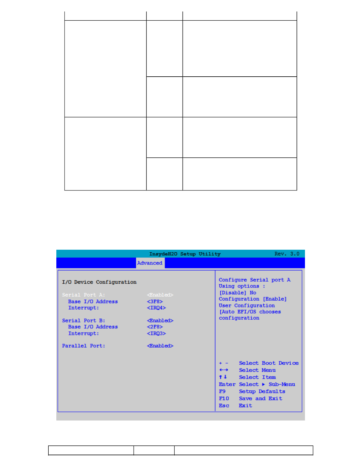
I/O Device Configuration
This configuration option allows you to assign Serial and Parallel port settings.
range.
Back-light Brightness Off Brightness is set to 0 across suspend,
resume and boot. Fn+F1 restores
brightness to the value it was set to
before suspend. Additionally,
Fn+F7 increases display brightness
gradually. Fn+F6 decreases
brightness gradually.
On Display brightness is preserved
across suspend/resume and boot. It
is restored to default when the
brightness level is set at 0. The
default level is mid-range.
Wireless Radios Off All wireless devices are set to off
during a suspend/resume or boot.
The radio on/off button can be used
to manually turn the radios on or off.
On The radio on/off button functions
normally and radio device power
states are held though
suspend/resume and boot.
Field Setting Function
Pa
g
e 48 of 70V
R
-2 Hel
p
4/26/2007file://C:\Documents and Settin
g
s\harwoodm\Local Settin
g
s\Tem
p
\~hh3F7F.htm
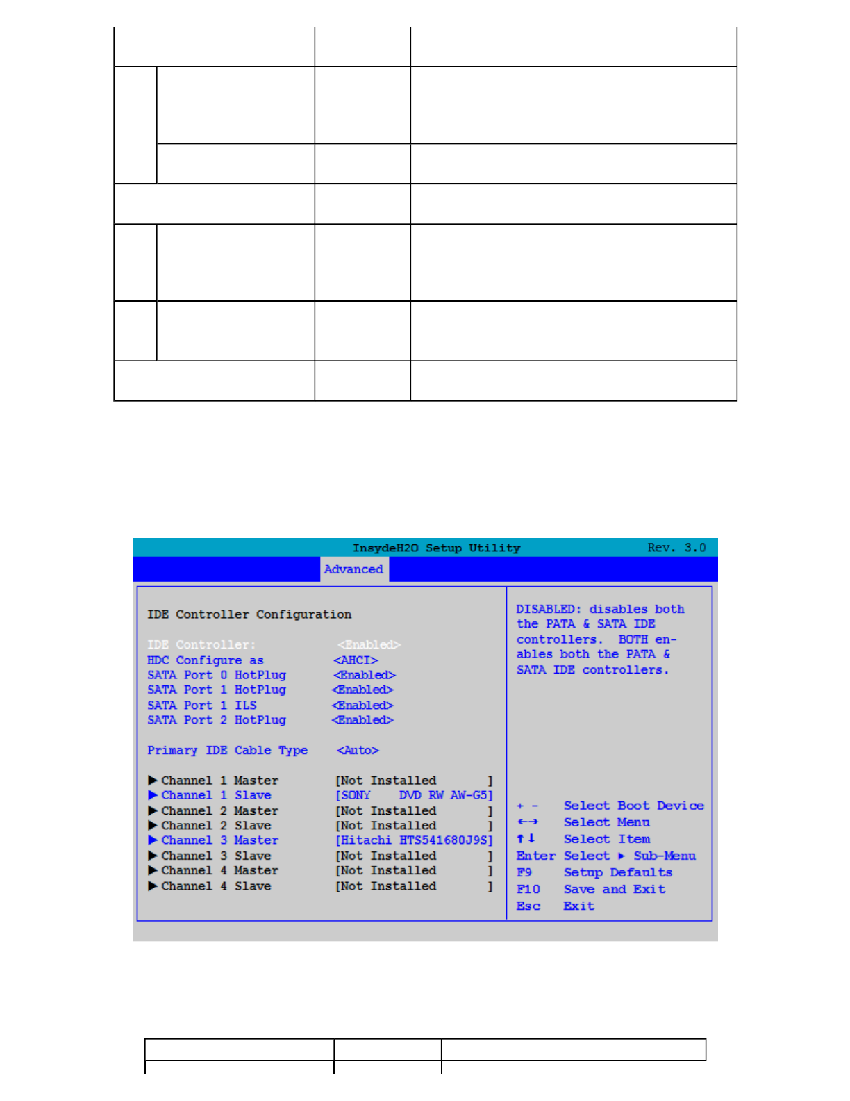
IDE Configuration
CAUTION Changes to the Primary Master setup may render the Hard Disk Drive unusable and result in data loss.
Serial Port A Enabled
Disabled User can configure this serial port when set
to enabled.
Base I/O address: 2E8
2F8
3E8
3F8
Sets the base I/O address for this serial port.
Interrupt: IRQ3
IRQ4 Sets the interrupt request of this serial port.
Serial Port B Enabled
Disabled User can configure this serial port when set
to enabled..
Base I/O address: 2E8
2F8
3E8
3F8
Sets the base I/O address for this serial port.
Interrupt:
IRQ3
IRQ4 Sets the interrupt request of this serial port.
Parallel
Port: Enabled
Disabled User can configure this parallel Port when set
to enabled.
Field Setting Function
Pa
g
e 49 of 70V
R
-2 Hel
p
4/26/2007file://C:\Documents and Settin
g
s\harwoodm\Local Settin
g
s\Tem
p
\~hh3F7F.htm

The Security Menu
You can set, chan
g
e or remove
p
asswords in the Securit
y
menu.
IDE Controller Enabled
Disabled If enabled, both the PATA and
SATA IDE Controllers are enabled.
If disabled, both the PATA and
SATA IDE controllers are disabled.
HDC Configure as PATA Only
SATA Only
IDE
Combined
IDE Non-
Combined
AHCI
Sets the Harddisk Controller
Configuration Type.
SATA Port 0 Hotplug Enabled
Disabled If enabled, the SATA Port 0
Hotplug is enabled.
SATA Port 1 Hotplug Enabled
Disabled If enabled, the SATA Port 1
Hotplug is enabled.
SATA Port 1 ILS Enabled
Disabled If enabled, the SATA Port 1
InterLock Switch is enabled.
SATA Port 2 Hotplug Enabled
Disabled If enabled, the SATA Port 2
Hotplug is enabled.
Primary IDE Cable Type Auto
40 Pins
80 Pins
Determines the type of IDE Cable
used.
Channel 1 Master Not
Installed If a drive is installed, its
manufacturer, drive type, and model
are displayed. Pressing [Enter]
displays additional drive and setting
information:
Type : <Auto/User Defined>
If USER Defined is enabled, the
following settings can be changed:
32Bit I/O
<Enabled/Disabled>
Block Mode:
<Enabled/Disabled>
Transfer Mode:
<Enabled/Disabled>
Security Mode:
Channel 1 Slave (Drive
Model)
Channel 2 Master Not
Installed
Channel 2 Slave Not
Installed
Channel 3 Master (Drive
Model)
Channel 3 Slave Not
Installed
Channel 4 Master Not
Installed
Channel 4 Slave Not
Installed
Pa
g
e 50 of 70V
R
-2 Hel
p
4/26/2007file://C:\Documents and Settin
g
s\harwoodm\Local Settin
g
s\Tem
p
\~hh3F7F.htm
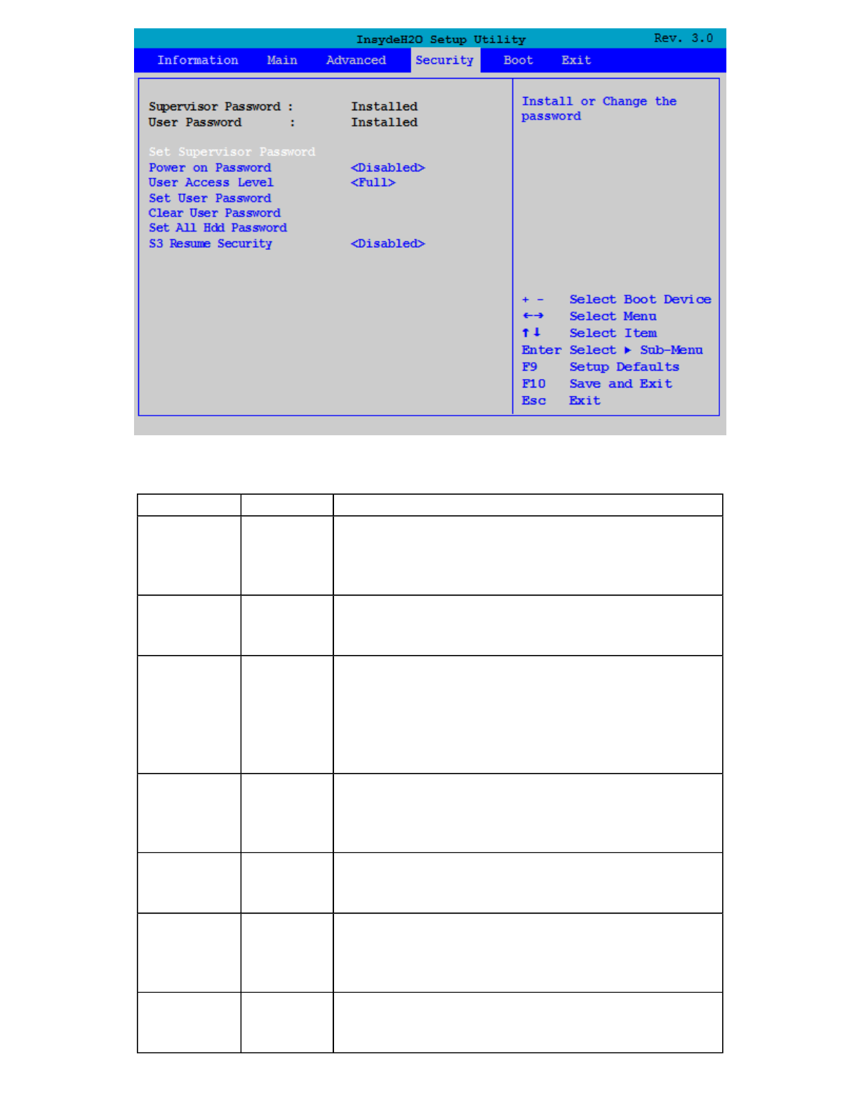
Note: This is the Security screen as seen when both Supervisor and User passwords are installed.
Field Setting Function
Set
Supervisor
Password
Enter
New
Password
Supervisor Password controls access to the Setup
Utility
Power on
password* Enabled
Disabled
If enabled, system will ask for password on post time.
If disabled, system will ask for password when
entering setup utility.
User
Access
Level*
View
Only
Limited
Full
If View Only, no system changes may be made by the
user. If Limited, some system changes may be made.
If Full, the user may make any system changes
except Supervisor Password.
Set User
Password Enter
New
Password
User Password controls access to the system
Clear User
Password** Yes
No
Removes the User Password.
Set All Hdd
Password Enter
New
Password
Use the hard disk drive password to prevent
unauthorized access to the hard disk
S3 Resume
Security Enabled
Disabled
If enabled, Resume S3 will check the BIOS and
Harddisk security
Pa
g
e 51 of 70V
R
-2 Hel
p
4/26/2007file://C:\Documents and Settin
g
s\harwoodm\Local Settin
g
s\Tem
p
\~hh3F7F.htm
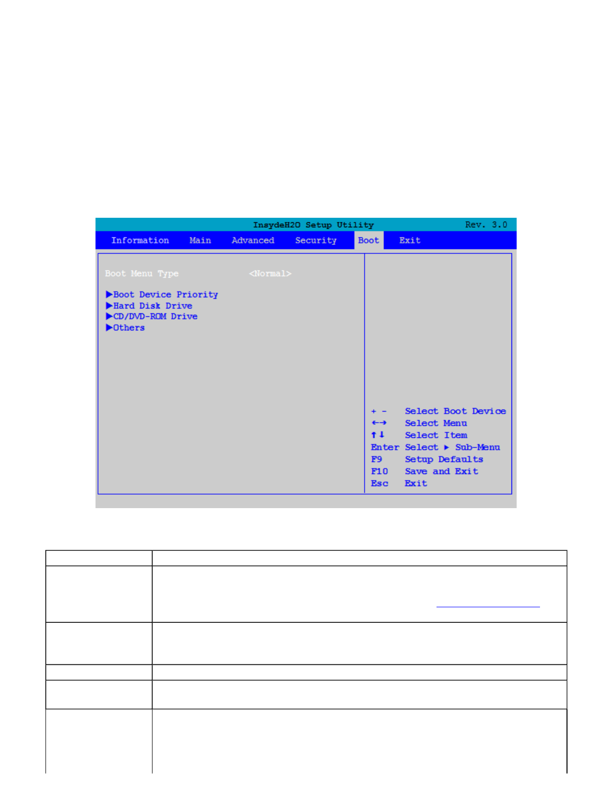
* Not displayed if Supervisor Password not installed.
** Not displayed if User Password not installed.
The Boot Menu
Use this menu to set the order of priority for devices from which the system will boot. Your computer automatically
detects the available devices. When you select a device, it is disabled in the other boot device fields.
To change the priority order, use the up and down arrow keys to highlight a device. Then press F5 or F6 to move
the device higher or lower on the priority list.
Field Function
Boot Menu Type Normal -- Displays the normal menu seen above.
Advance --Displays boot drive order by device name (see Boot Advance Menu
below).
Boot Device
Priority Displays boot drive order. First listed drive is the primary boot drive. Use up and
down arrow keys to highlight a drive device. User +/- keys to move the device up
or down the list.
Hard Disk Drive Displays manufacturer and serial number of hard drive
CD/DVD-ROM
Drive Displays manufacturer and serial number of CD/DVD-ROM drive
Others Allows boot from other devices such as:
z Network boot capability which allows boot up from a network drive.
Pa
g
e 52 of 70V
R
-2 Hel
p
4/26/2007file://C:\Documents and Settin
g
s\harwoodm\Local Settin
g
s\Tem
p
\~hh3F7F.htm
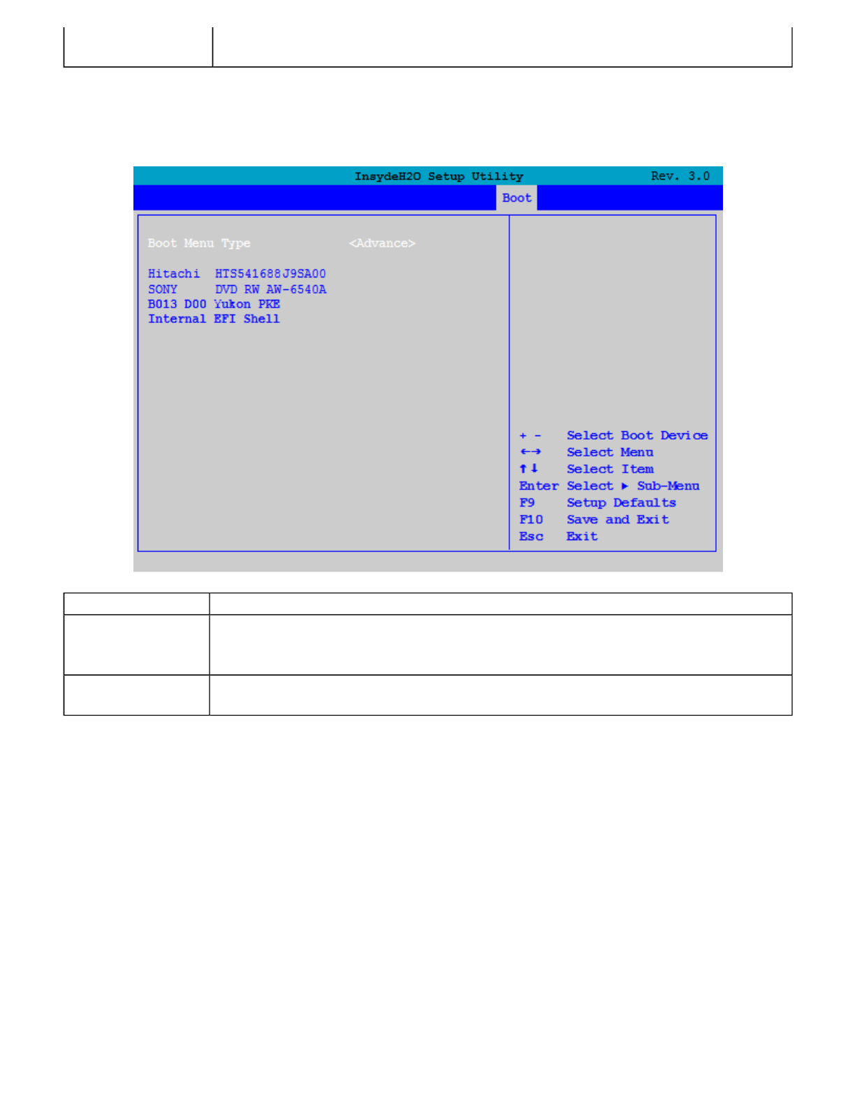
Boot Advance Menu
The Exit Menu
z Internal EFI (Extensible Firmware Interface) shell boot capability which
allows boot up from an alternate firmware chip set.
Field Function
Boot Menu Type Normal -- Displays the normal boot menu.
Advance --Displays boot drive order by device name.
(Device Name) First listed drive is the primary boot drive. Use up and down arrow keys to
highlight a drive device. User +/- keys to move the device up or down the list.
Pa
g
e 53 of 70V
R
-2 Hel
p
4/26/2007file://C:\Documents and Settin
g
s\harwoodm\Local Settin
g
s\Tem
p
\~hh3F7F.htm
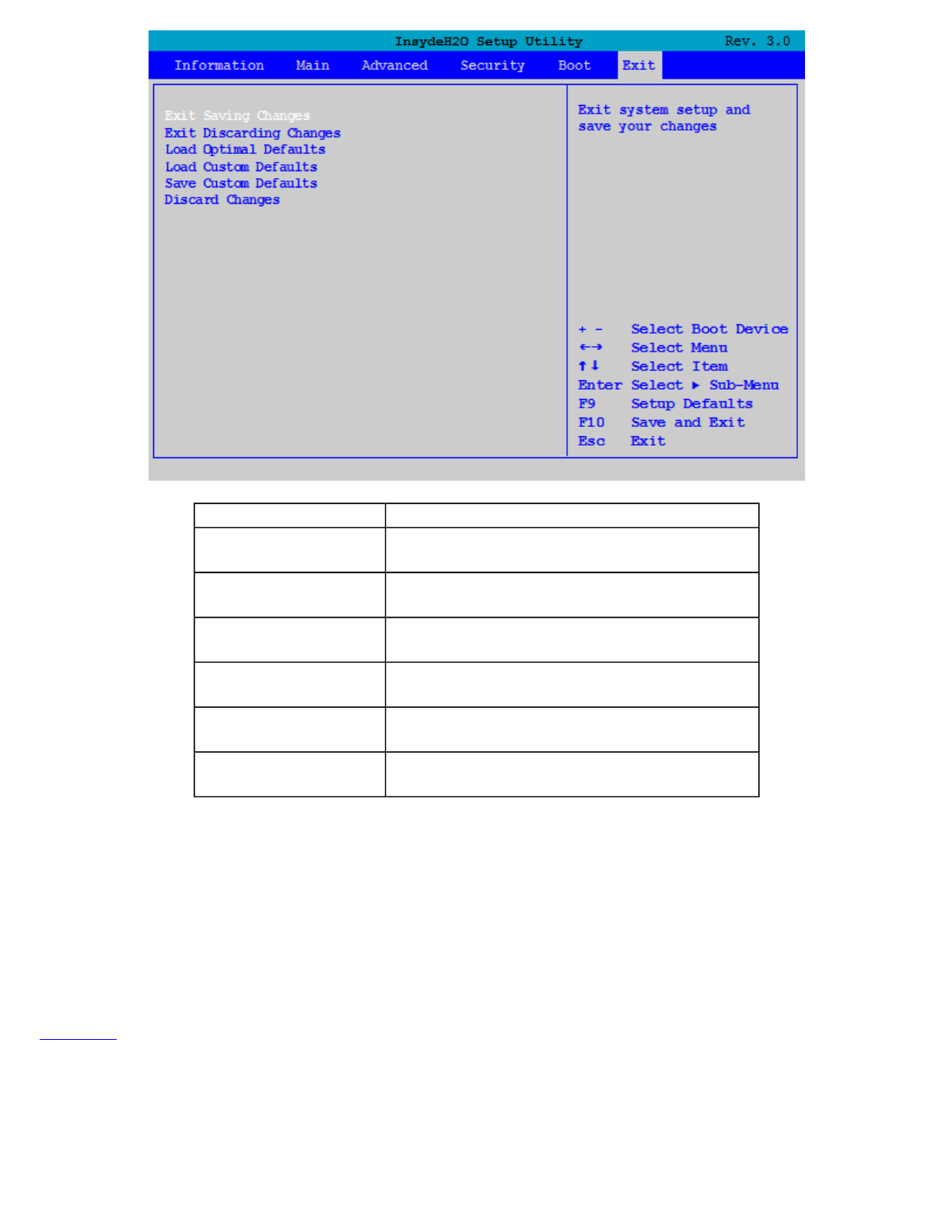
Optional Equipment and Accessories
Your computer delivers superior power and performance. However, some users and the applications they use may
demand more. This computer allows you to upgrade key components when you need increased performance.
NOTE Contact your authorized dealer if you decide to perform a key component upgrade.
Additionally, the GoBook VR-2 has several equipment and accessory options to further enhance your mobile
computing experience. This section highlights some of the most popular accessories used with the GoBook VR-2.
Click here for a complete list of optional peripherals and accessories.
CAUTION When purchasing any additional accessories, purchase only those accessories that are approved for use
with your computer. If you use items that are not approved for use with this computer, you may cause your
computer to malfunction, or to emit or receive electromagnetic radiation in excess of local regulations. For non-
p
roprietary accessories such as PC Cards or printers, ensure that the accessory functions properly with your
com
p
uter before makin
g
the
p
urchase.
Field Function
Exit Saving Changes Exit the Setup Utility and save the changes to
CMOS
Exit Discarding
Changes Exit the Setup Utility without saving Setup
data to CMOS
Load Optimal
Defaults Load Optimal " factory" default values for all
Setup options
Load Custom
Defaults Load custom made default values for all Setup
options
Save Custom
Defaults Save Setup data to CMOS but do not exit the
Setup Utility
Discard Changes Load the previously set values from CMOS
for all Setup options
Pa
g
e 54 of 70V
R
-2 Hel
p
4/26/2007file://C:\Documents and Settin
g
s\harwoodm\Local Settin
g
s\Tem
p
\~hh3F7F.htm
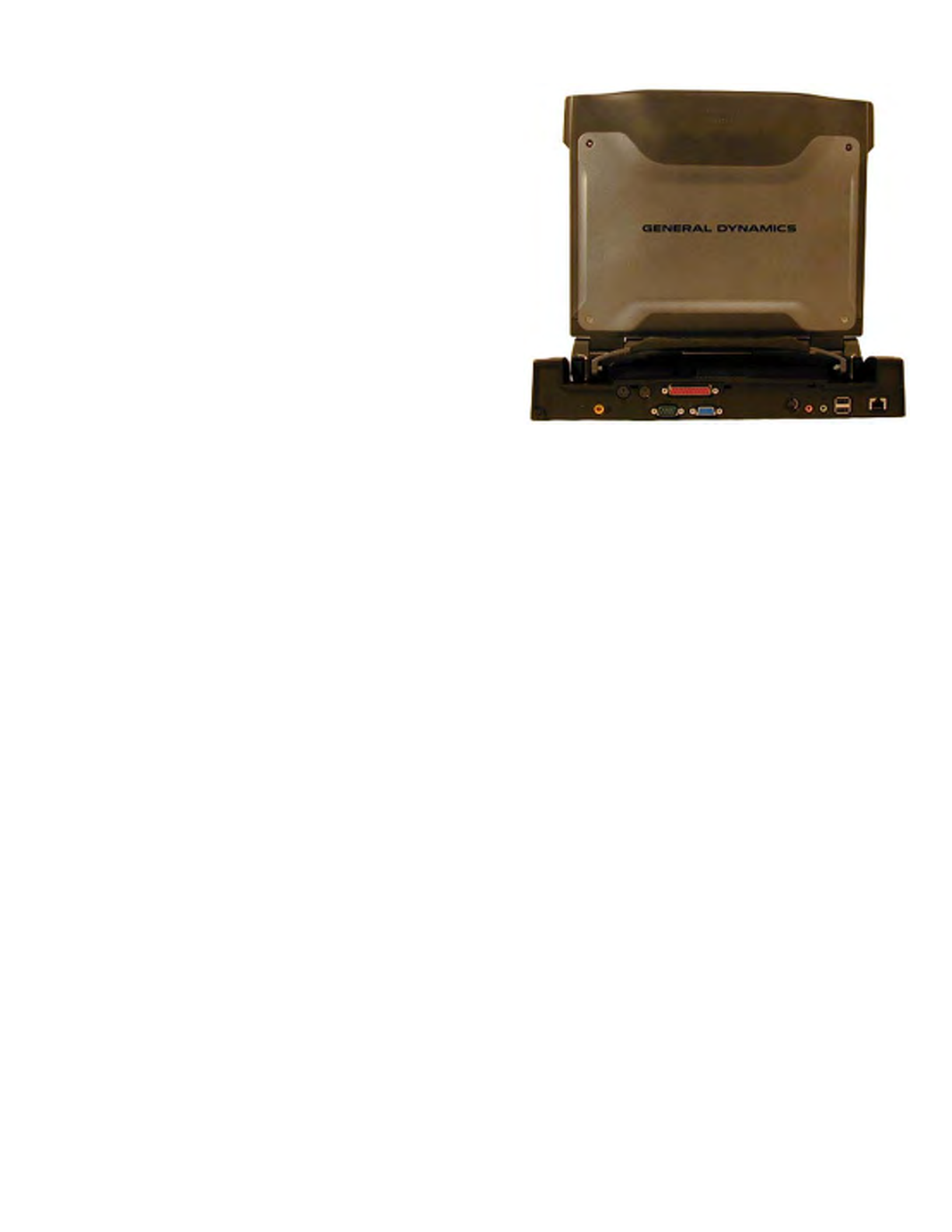
Office Dock
The GoBook VR-2's Office Dock enables you to use it as a
desktop computer. Once setup, the dock provides drop-in
convenience with no cables to attach or detach from your
GoBook VR-2. Simply place the computer in the dock and turn
it on. The Office Dock allows you to continue to access all
your computer's ports and bays. Additionally, it includes the
following ports typical of a business-class desktop computer:
zFour USB 2.0 ports
zIEEE 1394 port (FireWire™)
zRJ-45 10/100/1000 Ethernet port
zS-Video port
z9-pin legacy serial port
z25-pin parallel port
z15-pin external monitor/CRT port
zTwo PS/2 ports so you can attach a mouse and a keyboard
zDC-in power port
zMono microphone interface
zStereo speaker interface
Once in the dock, the computer's battery is recharged and conditioned automatically whether the computer is active,
suspended or even powered off.
Undocking the VR-2
The VR-2 must be undocked prior to removing it from the Office or Vehicle Dock.
To undock your VR-2:
1. Click on Start to display the Start Menu. (At the bottom of the Start Menu next to the Log Off and
Shutdown commands will be the Undock Computer command. )
2. Click on Undock Computer
3. Wait for the system to display "Windows has finished undocking the system. If you need to remove the system
from the Docking Station, please do so now."
4. Open the Start Menu once more and make sure the Undock Computer menu item is no longer displayed
before pressing the release button on the Docking Station.
Vehicle Dock
Pa
g
e 55 of 70V
R
-2 Hel
p
4/26/2007file://C:\Documents and Settin
g
s\harwoodm\Local Settin
g
s\Tem
p
\~hh3F7F.htm
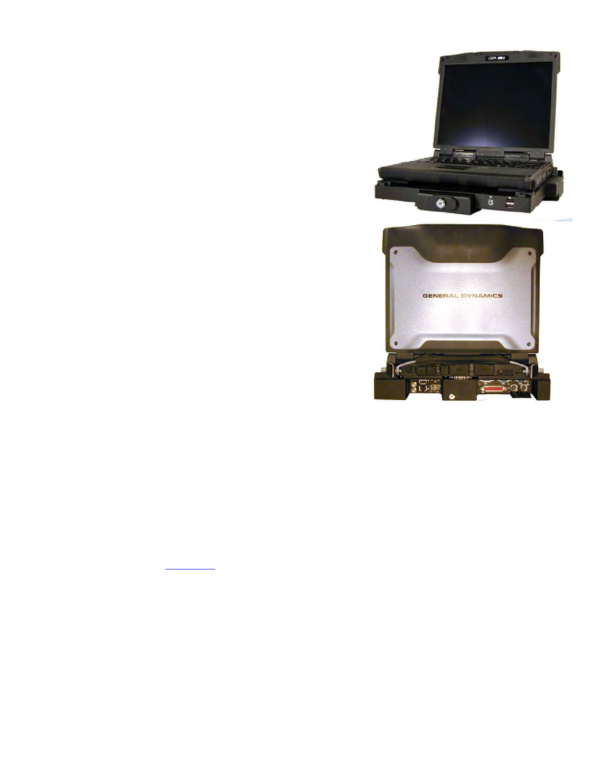
NOTE Be sure to follow the undocking procedure at the end of the Office Dock section
Surge Protection
A large number of computer and high technology equipment damage is directly related to AC power and telephone
line problems. These problems can include surges, spikes, noise, interference, and weather-related problems, which
in turn can cause glitches, hang-ups, crashes, performance slow downs, and down time with computer equipment.
The market is flooded with hundreds of AC power line surge suppressors advertising high performance surge
p
rotection; only a few of them actually provide adequate protection.
This section provides guidelines for selecting a quality surge suppressor to be used with your GoBook VR-2, and it
helps identify a few sources for products with acceptable performance.
Selectin
g
the Ri
g
ht Sur
g
e Protection
The optional vehicle dock enables you to use and recharge your GoBook
VR-2 quickly and efficiently in the your vehicle. Once setup, it provides
drop-in convenience with no cables to attach or detach to your GoBook
VR-2 when you enter or leave your vehicle. Simply place the computer
in the dock and turn it on. Once attached to the Vehicle Dock, the
computer's battery is recharged and conditioned automatically wether the
computer is active, suspended or even powered off.
Vehicle Dock features:
zCompliance with extensive vehicle environment requirements
(including crash test)
zKey lock to help prevent theft
zFour USB 2.0 ports (two in front and two in back)
zIEEE 1394 port (FireWire™)
zTwo 9-pin legacy serial ports
z25-pin parallel port
z15-pin external monitor/CRT port
zTwo PS/2 ports
zDC-in power port
zEthernet (LAN) port
zRemote power switch feature that is identical in function to the
main power button
zMono microphone interface
zStereo speaker interface
zTwo external antenna SMA connectors for WWAN and WLAN
Pa
g
e 56 of 70V
R
-2 Hel
p
4/26/2007file://C:\Documents and Settin
g
s\harwoodm\Local Settin
g
s\Tem
p
\~hh3F7F.htm

Consider the level of quality you need when selecting a surge suppressor. This depends on factors such as surge
environment, the type of equipment to be protected, and the quality of the electrical wiring and service.
Surge Environment
Surge environment refers to the damage potential from electrical surges in a particular geographical area. A high
quality suppressor should be used if there is frequent lightning activity in the area and the location service is fed by
overhead utility poles.
Type of Equipment to be Protected
If the computer is equipped with a modem, the modem should also be surge protected. Protecting the power line
without protecting the modem line provides only partial protection.
Quality of Electrical Wiring and Service
Wiring should be up to current local standards and have verified good AC grounds. It is important that your
computer system be plugged into a grounded AC outlet when charging and that all peripherals connected to your
system reference the same AC ground.
Selecting the Right Equipment
There are a number of companies that sell quality surge suppressors. When looking for a surge suppressor, consider
these things.
zExpect to pay more for a good quality surge suppressor
zThe surge suppressor should be a UL 1449, 497, and 1283 listed for surge suppression, modem surge
protection, and RFI/EMI noise filtering respectively
zThe surge suppressor should have diagnostic LEDs that verify good AC ground, proper wiring, and proper
surge operation. On/off switches that light are not recommended since they can produce electrical noise
zThe Joule ratings should be a minimum of 480 Joules for the AC surge circuit
zThe Joule ratings should be a minimum of 240 Joules for the modem
zThe modem surge circuit should present low capacitance to the modem line or it will slow the transmission
rate. Capacitance should be specified at less than 50 picofarads
zQuality surge suppressor manufacturers generally offer a lifetime warranty
zConsider obtaining a protected equipment coverage policy which insures the equipment in the event of surge
damage
zThe devices that will be attached to the computer also need to be surge protected
Memory Upgrade
Adding memory allows the computer to operate faster, handle more tasks simultaneously, and work more smoothly
with large files. Users who increase memory demands - by adding additional programs, for example - may notice a
slowdown in operating speed, and wish to increase memory. The GoBook VR-2 comes with one user accessible
memory socket supporting a 512MB to 1024MB memory module for memory upgrades. Please consult your dealer
if
y
ou need to add more memor
y
.
Pa
g
e 57 of 70V
R
-2 Hel
p
4/26/2007file://C:\Documents and Settin
g
s\harwoodm\Local Settin
g
s\Tem
p
\~hh3F7F.htm
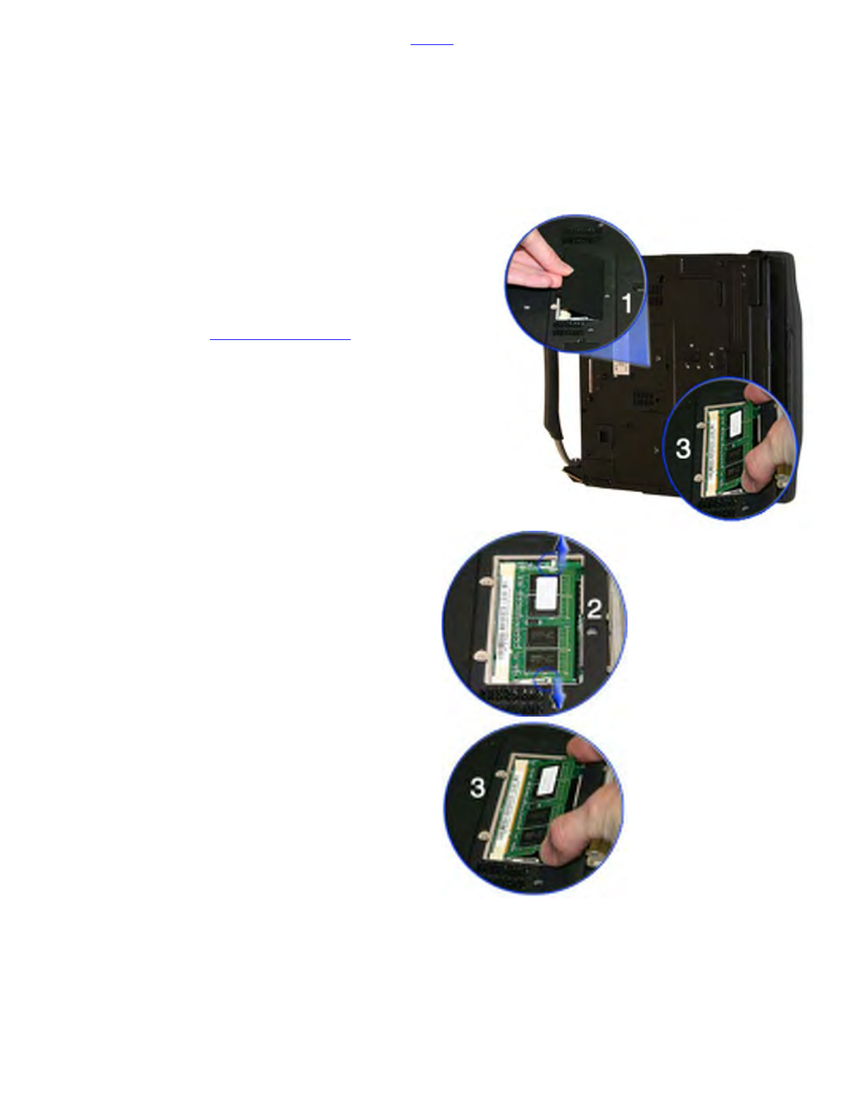
CAUTION First read and follow the guidelines in the Safety section.
Replacing a Memory Card
CAUTION Memory modules can be easily damaged by static electricity. Leave the module inside its static-proof
bag until it is ready for installation and make sure you are grounded before attempting this procedure.
Removing a Memory Card
Inserting a Memory Card
CAUTION Only use memory cards approved for use in your computer. Failure to do so may void your warranty.
1. Hold the memory card by its edges with the edge-connector side towards the slot.
CAUTION Do not touch the memory card anywhere except the edges.
2. Hold the card at a shallow an
g
le
(
about 25 de
g
rees
)
and insert the ed
g
e connector into the connector slot. The
1. Turn off the computer and disconnect the AC
adapter.
2. Turn the computer upside down and lay it on a flat
surface.
3. Remove the battery (see Battery Removal).
4. Carefully remove the two RAM compartment cover
screws and remove the RAM compartment cover
(1).
5. If a memory card is inserted, use your finger to
gently pull the tabbed latches in the direction of the
arrows (2). The card will pop up slightly.
CAUTION Do not use tools to pull the memory
card latches. Tools may cause damage.
6. Pull upwards on the card and then slide the card out
(3).
Pa
g
e 58 of 70V
R
-2 Hel
p
4/26/2007file://C:\Documents and Settin
g
s\harwoodm\Local Settin
g
s\Tem
p
\~hh3F7F.htm

"gold teeth" of the edge connector should no longer be visible when the card is fully inserted. (See image 3
above).
3. Press the card downwards so that it is flat inside the compartment. You may hear an audible click as the
latches of the connector lock the card in place.
4. Replace the RAM compartment cover and secure it with the two screws.
CAUTION If the cover does not close easily, do not force it. The memory card may not be properly installed.
Carefully remove and reinstall the card following the steps above.
Your notebook computer will automatically detect the change in RAM capacity when it restarts. You can verify
RAM capacity has changed in the Setup Utility or in Windows:
1. Setup: Press F2 during boot-up when you see the "Press F2 to enter Setup" prompt. The information menu
shows the base memory and the extended memory.
2. Windows: Right click on my computer and select properties to open System Properties. The General tab
lists the memory detected by Windows.
Miscellaneous options
Battery pack
It is a good practice to have a spare battery around, especially when you travel. The Li-ion battery, coupled with the
p
ower management features of your computer, supplies you with more power on-the-go. You may also purchase a
secondary 9 cell battery pack for longer run time.
AC adapter
The compact AC adapter charges your battery pack and supplies power to your computer. You can order a spare AC
adapter so you do not need to carry it from the office to your home or destination.
Vehicle adapter
The vehicle adapter supplies power from the vehicle battery to your computer. It attaches to your computer's DC
p
ower port and typically plugs into the cigarette lighter socket in your vehicle.
Other Options and Accessories
Click here for a complete list of optional peripherals and accessories.
Maintenance and Storage
Follow the guidelines in this section to care for your computer.
Computer Maintenance and Storage
You can use your computer under a wide range of environmental conditions. However, to ensure long use and
continued high performance, consider the following factors when using your computer:
Taking Care of Your Computer
zFollow all warnin
g
s and instructions noted in this documentation and in the Windows Hel
p
p
ro
g
ram
Pa
g
e 59 of 70V
R
-2 Hel
p
4/26/2007file://C:\Documents and Settin
g
s\harwoodm\Local Settin
g
s\Tem
p
\~hh3F7F.htm

zThe first time you use your computer, we recommend that you carefully read the Making Connections section
and initialize the battery to ensure optimum battery performance
zUnplug the computer from the power outlet before cleaning. Use a damp cloth for cleaning. Do not use
aerosols, solvents, or strong detergents
zSlots and openings in the unit's case are for ventilation purposes. Do not block or cover these openings or the
system could overheat. Do not use or store the computer near a source of heat or dust
zIf you use the computer with an extension cord, ensure that the total ampere ratings of all the devices sharing
the extension do not exceed the rating of the extension cord or the rating of the wall outlet
zNever push foreign objects into the computer through any of the slots or openings. Dangerous voltages are
present, which could cause electric shock or fire, or damage sensitive components
zFor best results, use a power strip with a built-in surge protector. Do not use inferior extension cords as this
may result in damage to your computer
zSet the computer on a flat, stable surface. To prevent damage to the computer’s hard disk drive, avoid using
the computer where it will be exposed to strong vibration
zDo not place it near sources of heat, such as a radiator
zDo not expose the computer to temperatures below -20ºC (-4ºF) or above 60ºC (140ºF)
zDo not subject the computer to magnetic fields
zDo not expose the computer to rain or moisture
zDo not spill liquid on the computer
zDo not subject the computer to heavy shock and vibration
zDo not expose the computer to dust and dirt
zDo not place objects on top of the computer
zDo not place the computer on uneven surfaces
zPeriodically inspect the computer and accessories for wear, damage, loose or missing parts. Identifying and
correcting potential problems early can help reduce the need to return the unit for service
Taking care of your AC adapter
zDo not connect the adapter to any other device
zDo not step on the power cord or place anything on top of it. Carefully route the power cord and any cables
away from all potential traffic
zWhen unplugging the power cord, do not pull on the cord itself but pull on the plug
zThe total ampere ratings of the equipment plugged in should not exceed the ampere rating of the cord if you
are using an extension cord. Also, the total current rating of all equipment plugged into a single wall outlet
should not exceed the fuse ratin
g
Pa
g
e 60 of 70V
R
-2 Hel
p
4/26/2007file://C:\Documents and Settin
g
s\harwoodm\Local Settin
g
s\Tem
p
\~hh3F7F.htm

Servicing
Contact your dealer or see your service technician if any of the following occurs:
z The computer has been dropped or the body has been damaged
z Liquid has been spilled into the product
z The computer does not operate normally
See the Service and Support section for more information.
Battery Maintenance and Storage
Taking care of your battery pack
zUse only batteries of the same kind as replacements. Turn the power off before removing or replacing
batteries
zDo not tamper with batteries. Keep them away from children
zDispose of used batteries according to local regulations. Recycle if at all possible
Maintaining Batteries
Follow these guidelines to maintain performance of Lithium-Ion (Li-on) batteries.
zAvoid exposing batteries to extremely hot or cold temperatures for long periods. To prevent possible damage
to the battery, the GoBook VR-2 does not allow the battery to charge if the internal temperature of the battery
gets too low (< 5°C or < 41°F) or too high (> 50°C or > 122°F)
zCharge the battery nightly where the temperature will remain around 20°C (68°F)
zRe-calibrate your battery every three months or when your battery performance degrades
Storing Batteries
zBefore storing, discharge the battery to 50%
zStore the battery as close to close to 10°C (50F°) as possible
zIt is recommended that you cycle a stored battery once every three months
zUnused or stored batteries can lose power over time. When you install a battery that has not been used for
awhile, connect external power to the computer and charge the battery
zAfter storage, battery calibration may increase its capacity
Cleaning Your Computer
Outside Case Like all tools, the outside of the computer will get dirty with use. To clean the outside case, follow
the
p
rocedure below.
Pa
g
e 61 of 70V
R
-2 Hel
p
4/26/2007file://C:\Documents and Settin
g
s\harwoodm\Local Settin
g
s\Tem
p
\~hh3F7F.htm

Disconnect external power and turn off the computer.
Add a small amount of water to a soft cloth and clean the computer case. Do not use paper products because they
can scratch the surface.
Wipe off any excess liquid with a soft cloth.
Display Periodically inspect the display to make sure the brightness function is operating properly and that all
p
ixels are operational. To clean the display assembly, use a soft, dry cloth. In some cases, you can use a small
amount of water to remove streaks or smears. Do not use paper products because they can scratch the screen.
External Power Connector The external power connector may sometimes be exposed to moisture and/or
contamination causing an unreliable connection to the external power source.
Clean the connector with a cotton swab dipped in isopropyl alcohol.
RJ-11/ RJ-45 / USB Connectors If the connector pins get dirty, clean the connector with a cotton swab dipped in
isopropyl alcohol.
Troubleshooting
This section is designed to help you determine and fix problems you might encounter while operating the GoBook
VR-2. Try the following things in order:
1. First look through the categories in this section for a solution.
2. If you are having a problem with a computer application , use the Help that comes with the application to find
a solution.
3. If you still cannot resolve your problem, refer to Service and Support.
WARNING Do not attempt to open and service the computer by yourself. Contact your dealer or an authorized
service center for assistance.
Application Troubleshooting
My application locks up, acts strangely, or produces a General Protection Fault (GPF) error or blue screen
zPress CTRL+ALT+DEL to start the Logon Protector, select the Task Manager. Click the Applications tab
on the Task Manager and look for the application that is having problems. If the application is hung, the
Status column will say "Not Responding" after the task name. Click on the task/application, then click the
End Task button.
zIf you have tried to resolve the problem and your application still does not respond, you may need to restart
your computer.
To restart your computer, select Start, Shut Down, Restart. If that does not work, try pressing
CTRL+ALT+DEL twice.
If the computer does not restart, the keyboard may be locked up. Hold the Power Button for ten seconds or
use the reset on the bottom of the unit.
CAUTION This will result in a loss of all unsaved data.
Pa
g
e 62 of 70V
R
-2 Hel
p
4/26/2007file://C:\Documents and Settin
g
s\harwoodm\Local Settin
g
s\Tem
p
\~hh3F7F.htm

zThe data on the hard disk could be corrupted. Run SCANDISK.
zWindows may be out of memory or resources. Exit Windows and restart Windows by selecting Start, Shut
Down, Restart.
Battery Troubleshooting
The battery does not charge
The batteries take much longer than seven hours to charge
The batteries don’t last very long
The gas gauge isn’t full after charging the battery
The gas gauge reads “full,” but the indicator light is still blinking
My battery seems to have less and less capacity
Display Troubleshooting
The display performance is slow
I can’t read the display
The underlined, inverse, and hypertext characters are difficult to read on the screen
I changed my display resolution, but I see no difference on the screen
My screen seems to time out too quickly. I have to constantly hit a key or move the mouse in order to bring it back.
How can I adjust the screen time-out?
Hard Disk Troubleshooting
The hard disk will not spin up so the computer can’t boot up
Keyboard and Mouse Troubleshooting
Something unexpected happens when I press a key
Incorrect characters appear on the screen when I press certain keys
I have difficulty double-clicking the mouse fast enough
Modem Troubleshooting
The modem doesn’t work
The modem doesn’t dial a numbe
r
Pa
g
e 63 of 70V
R
-2 Hel
p
4/26/2007file://C:\Documents and Settin
g
s\harwoodm\Local Settin
g
s\Tem
p
\~hh3F7F.htm

The modem dials and receives an answer but does not establish a connection
Miscellaneous Troubleshooting
The computer shuts off unexpectedly
The speaker volume is too high or too low
The computer won’t turn on
The computer will not come on when the power button is pressed but the power, external power and battery
indicators flash in sequence.
The computer won’t turn off
The computer enters suspend mode too quickly
The computer doesn’t automatically suspend
The system date and time are incorrect
I receive an “out of memory” error message
PC Card Troubleshooting
I can’t remove the PC card
Diskette Read Error
The system does not recognize the PC Card CD-ROM when it is inserted into the PC Card socket
The computer locks up when I remove the PC card
FAQs
I've heard that cleaning up and rearranging files on the hard drive will improve the startup speed of my programs.
How do I do this?
How do I adjust the volume?
How do I change the battery?
How long will the battery last?
How do I change the display brightness?
How do I clean the display?
How do I calibrate the touch screen?
Service and Support
Pa
g
e 64 of 70V
R
-2 Hel
p
4/26/2007file://C:\Documents and Settin
g
s\harwoodm\Local Settin
g
s\Tem
p
\~hh3F7F.htm

We are committed to providing you world class support services that ensure the lowest total cost of ownership for
your hardware investment. The icareServices program will help you maximize end user productivity and decrease
overall system operating cost.
Client Care Center (CCC)
General Dynamics Itronix Corporation Client Care Center – The CCC is an internal central point for telephone
warranty support for all GD-Itronix products. Our Technical Service Representatives know your product and
p
rovide input and support for problem resolution.
One call to the convenient Client Care Center number (800-638-9270, Opt 2) <<1-800 numbers ARE NOT
accessible from Mexico!! allows a single entry point of access to meet all your needs. You may also use the new
web portal at www.GD-Itronix.com/CCC. The CCC receives calls from 5am-5pm Pacific Daylight Time, Monday
through Friday (except on holidays).
Technical Service Representatives provide the following support services:
z Product troubleshooting
z RMA origination for service return
z RMA status check on product service
z Check status Warranty/Service Kit orders
z Coordinate requests for product upgrades
z Wireless Radio registration
z icareServeNet registration and training
GD-Itronix offers service uplift programs for clients who wish to expand their support coverage beyond the
basic warranty. Coverage and details of these programs are available on line at www.gd-itronix.com
Product Support - Downloads
It is easy to get the software updates you need to keep your configuration current and get the most from your
p
roduct. Click here to get current downloads.
NOTE Downloads are listed by model (GoBook VR-2) and product number (IX605).
Documentation Feedback
We strive to create accurate, convenient and highly useful product documentation for all our products. With this in
mind, we'd like to hear from you and encourage your feedback. If you have comments or suggestions about our
online Help or other product documentation, click here to send us an email.
Please include the following information when submitting feedback:
zProduct name
zPlace and date of
p
urchase
Pa
g
e 65 of 70V
R
-2 Hel
p
4/26/2007file://C:\Documents and Settin
g
s\harwoodm\Local Settin
g
s\Tem
p
\~hh3F7F.htm

zName of online Help or other document
zTopic title (for online Help) or page number
zLocalized document language (such as English, French, German, Spanish)
zType of feedback (for example, need for clarification, grammatical errors, incorrect information)
zYour suggestion for how to improve the document
Identification
GoBook VR-2 (IX605)
Copyright Notice
© Copyright 2007 General Dynamics-Itronix Corporation. All rights reserved. No part of this document may be
reproduced, transmitted, transcribed, stored in a retrieval system, or translated into any other language or computer
language in whole or in part, in any form or by any means, whether it be electronic, mechanical, magnetic, optical,
manual, or otherwise, without the prior written consent of General Dynamics-Itronix Corporation, 12825 E.
Mirabeau Parkway, Spokane Valley, WA 99216.
Disclaimer
This document is printed in the U.S.A. GD-Itronix Corporation reserves the right to revise the manual and make
p
eriodic changes to the content without a direct or inferred obligation to GD-Itronix to notify any person of such
revision or changes. GD-Itronix Corporation does not assume responsibility for the use of this help manual, nor for
any patent infringements or other rights or third parties who may use the manual.
This document contains valuable trade secrets and proprietary information of GD-Itronix Corporation.
This product is available for purchase under General Dynamics-Itronix's standard terms and conditions of sale. GD-
Itronix hardware products may be reconditioned, or be manufactured from parts and components that may be new,
used, rebuilt, or recycled and in some cases, the hardware product may not be new and may have been previously
installed. In any event, GD-Itronix warranty terms apply.
Trademark and Patent Notice
Itronix is a registered trademark of GD-Itronix Corporation.
GoBook is a registered trademark of GD-Itronix Corporation
Microsoft, MS Windows, and MS-DOS are registered trademarks of Microsoft Corporation.
IBM is a trademark of International Business Machines Corporation.
The following United States Patent Numbers apply to any unit which incorporates a DVD drive - 5,434,678;
5,589,945; 5,913,013; 6,151,444; and 6,208,805.
Compliance Statements
Federal Communication Commission Interference Statement
This equipment has been tested and found to comply with the limits for a Class B digital device, pursuant to Part 15
of the FCC Rules. These limits are designed to provide reasonable protection against harmful interference in a
residential installation. This equipment generates, uses and can radiate radio frequency energy and, if not installed
and used in accordance with the instructions, may cause harmful interference to radio communications. However,
there is no
g
uarantee that interference will not occur in a
p
articular installation. If this e
q
ui
p
ment does cause harmful
Pa
g
e 66 of 70V
R
-2 Hel
p
4/26/2007file://C:\Documents and Settin
g
s\harwoodm\Local Settin
g
s\Tem
p
\~hh3F7F.htm

interference to radio or television reception, which can be determined by turning the equipment off and on, the user
is encouraged to try to correct the interference by one of the following measures:
• Reorient or relocate the receiving antenna.
• Increase the separation between the equipment and receiver.
• Connect the equipment into an outlet on a circuit different from that to which the receiver is connected.
• Consult the dealer or an experienced radio/TV technician for help.
FCC CAUTION
To assure continued compliance, (example - use only shielded interface cables when connecting to computer or
p
eripheral devices) any changes or modifications not expressly approved by the party responsible for compliance
could void the user's authority to operate this equipment.
This device complies with Part 15 of the FCC Rules. Operation is subject to the following two conditions:
(1) This device may not cause harmful interference, and
(2) This device must accept any interference received, including interference that may cause undesired operation.
IMPORTANT NOTE
FCC Radiation Exposure Statement
This equipment complies with FCC radiation exposure limits set forth for an uncontrolled environment. This
equipment should be installed and operated with minimum distance 20cm between the radiator and your body.
This transmitter must not be co-located or operating in conjunction with any other antenna or transmitter.
Local Restriction of 802.11a/b/g/n Radio Usage
CAUTION Due to the fact that the frequencies used by 802.11a/b/g/n wireless LAN devices may not yet be
harmonized in all countries, 802.11a/b/g/n products are designed for use only in specific countries, and are not
allowed to be operated in countries other than those of designated use. As a user of these products, you are
responsible for ensuring that the products are used only in the countries for which they were intended and for
verifying that they are configured with the correct selection of frequency and channel for the country of use. Any
deviation from permissible settings and restrictions in the country of use could be an infringement of national law
and may be punished as such.
FCC Radio Frequency Interference Requirements
This device is restricted to indoor use due to its operation in the 5.15 to 5.25 GHz frequency range. FCC requires
this product to be used indoors for the frequency range 5.15 to 5.25 GHz to reduce the potential for harmful
interference to co-channel Mobile Satellite systems. High power radars are allocated as primary users of the 5.25 to
5.35 GHz and 5.65 to 5.85 GHz bands. These radar stations can cause interference with and /or damage this device.
REN
The GoBook VR-2 (IX605) computer complies with Part 68 of the FCC Rules. On the bottom of this equipment is a
label that contains, among other information, the FCC registration number and ringer equivalence number (REN) for
this e
q
ui
p
ment. If re
q
uested, this information must be
p
rovided to the tele
p
hone com
p
an
y
.
Pa
g
e 67 of 70V
R
-2 Hel
p
4/26/2007file://C:\Documents and Settin
g
s\harwoodm\Local Settin
g
s\Tem
p
\~hh3F7F.htm

The REN is used to determine the quantity of devices which may be connected to the telephone line. Excessive
RENs on the telephone line may result in the devices not ringing in response to an incoming call. In most, but not all
areas, the sum of the RENs should not exceed five (5.0). To be certain of the number of devices that may be
connected to the line, as determined by the total RENs, contact the telephone company to determine the maximum
REN for the calling area.
The GoBook VR-2 (IX605) computer may be connected to the telephone network using the RJ-11 jack provided.
If this equipment causes harm to the telephone network, the telephone company will notify you in advance that
temporary discontinuance of service may be required. If advance notice isn’t practical, the telephone company will
notify the customer as soon as possible. Also, you will be advised of your right to file a complaint with the FCC if
you believe it is necessary.
The telephone company may make changes in its facilities, equipment, operations, or procedures that could affect
the operation of the equipment. If this happens, the telephone company will provide advance notice in order for you
to make the necessary modifications in order to maintain uninterrupted service.
If trouble is experienced with this equipment, please contact the equipment manufacturer for repair and/or warranty
information. Do not attempt repairs of this equipment yourself without obtaining manufacturer authorized parts and
documentation. If the trouble is causing harm to the telephone network, the telephone company may request you
remove the equipment from the network until the problem is resolved.
Compliance Statement for Canada
NOTICE The Industry Canada label identifies certified equipment. This certification means that the equipment
meets certain telecommunications network protective, operational and safety requirements as prescribed in the
appropriate Terminal Equipment Technical Requirements document(s). The Department does not guarantee the
equipment will operate to the user’s satisfaction.
Before installing this equipment, users should ensure that it is permissible to be connected to the facilities of the
local telecommunications company. The equipment must also be installed using an acceptable method of
connection. The customer should be aware that compliance with the above conditions may not prevent degradation
of service in some situations.
Repairs to certified equipment should be made by a representative designated by the supplier. Any repairs or
alterations made by the user to this equipment, or equipment malfunctions, may give the telecommunications
company cause to request the user to disconnect the equipment.
Users should ensure for their own protection that the electrical ground connections of the power utility , telephone
lines, and internal metallic water pipe system, if present, are connected together. This precaution may be particularly
important in rural areas.
CAUTION! Users should not attempt to make such connections themselves, but should contact the appropriate
electric inspection authority, or electrician, as appropriate.
The Ringer Equivalence Numbers (REN) are:
GoBook VR-2 (IX605) non-radio: 0.5B
NOTICE The Ringer Equivalence Number (REN) assigned to each terminal device provides an indication of the
maximum number of terminals allowed to be connected to a telephone interface. The termination on an interface
may consist of any combination of devices subject only to the requirement that the sum of the Ringer Equivalence
N
umbers of all the devices does not exceed 5.
The GoBoo
k
V
R
-2
(
IX605
)
com
p
uter ma
y
be connected to the tele
p
hone network usin
g
the RJ-11
j
ack
p
rovided.
Pa
g
e 68 of 70V
R
-2 Hel
p
4/26/2007file://C:\Documents and Settin
g
s\harwoodm\Local Settin
g
s\Tem
p
\~hh3F7F.htm

Fax Branding
The Telephone Consumer Protection Act of 1991 makes it unlawful for any person to use a computer or other
electronic device to send any message via a telephone fax machine unless such message clearly contains in a margin
at the top or bottom of each transmitted page or on the first page of the transmission, the date and time it is sent and
an identification of the business or other entity, or other individual sending the message and the telephone number o
f
the sending machine or such business, other entity, or individual.
In order to program this information into your fax machine, you should complete the following:
This information is entered through the FAX application software you have installed. Consult your FAX software
documentation for instructions about entering this information.
Warnings and Cautions
WARNING It is important that only authorized GD-Itronix personnel attempt repairs on GD-Itronix equipment as
this might void any maintenance contract with your company. Unauthorized service personnel might be subject to
shock hazard on some GD-Itronix equipment if removal of protective covers is attempted.
The product you have purchased is powered by a rechargeable battery. The battery is recyclable and, under various
state and local laws, it may be illegal to dispose of this battery into the municipal waste stream. Do not crush the
battery or place it in a fire. Check with your local solid-waste officials for details on recycling options or proper
disposal.
CAUTION Internal components of the GoBook VR-2 (IX605) computer will be damaged if exposed to
contaminants. When dust covers, the PC card door, or the bottom access panel are open on the computer, shield the
unit from all contaminants such as liquids, rain, snow, and dust.
Internal radio(s) may have an individual FCC Identifier which are not applicable to this configuration. Only the FCC
ID shown on the label located on the bottom of the IX605 Laptop PC is applicable. The IX605 computer must not be
co-located or operating in conjunction with any other antenna or transmitter than specified in the filing .
This device may contain a WLAN radio transmitter , a WAN radio transmitter and a PAN radio transmitter. To
comply with FCC RF exposure requirements when using the WAN radio transmitter, a minimum separation distance
of 20 cm must be maintained between the between the center of the display screen and all users/bystanders. When
using the WLAN transmitter, a minimum separation distance of 20 cm must be maintained between the upper right
and left edges of the display screen and all users/bystanders. When using the Pan transmitter, a minimum separation
distance of 20 cm must be maintained between the lower left edges of the Keyboard and all users/bystanders. The
WAN radio and WLAN/PAN transmitter should be turned off before carrying the Laptop PC order to comply with
FCC RF exposure requirements.
"The equipment has been approved to [Commission Decision "CTR21"] for pan-European single terminal
connection to the Public Switched Telephone Network (PSTN). However, due to differences between individual
P
STNs provided in different countries the approval does not, of itself, give an unconditional assurance of successful
operation on every PSTN network termination point.
I
n the event of problems, you should contact your equipment supplier in the first instance.
This product is intended to be supplied by a Listed Power Unit and output rated 19 V dc, 3.42 A.
CAUTION Always disconnect all telephone lines from the wall outlet before servicing or disassembling this
equipment.
CAUTION To reduce the risk of fire use onl
y
a No. 26 AWG or lar
g
er telecommunication line cord.
Pa
g
e 69 of 70V
R
-2 Hel
p
4/26/2007file://C:\Documents and Settin
g
s\harwoodm\Local Settin
g
s\Tem
p
\~hh3F7F.htm

Safety Information
Enclosed with each IX605 Laptop computer is the radio specific safety information. Do not proceed without
reviewing the information provided in that document.
Do not
p
roceed be
y
ond a WARNING or CAUTION until the indicated conditions are full
y
understood and met.
Pa
g
e 70 of 70V
R
-2 Hel
p
4/26/2007file://C:\Documents and Settin
g
s\harwoodm\Local Settin
g
s\Tem
p
\~hh3F7F.htm