General Dynamics Itronix IX250RIM902 Rugged Laptop PC with RIM 902 Mobitex Radio Modem User Manual GoBook
General Dynamics Itronix Corporation Rugged Laptop PC with RIM 902 Mobitex Radio Modem GoBook
Contents
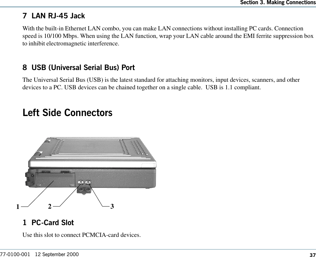
- 1. Users Manual
- 2. IX550 Users Manual
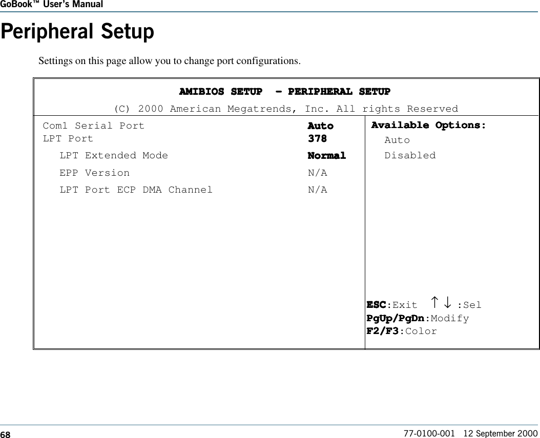
Users Manual

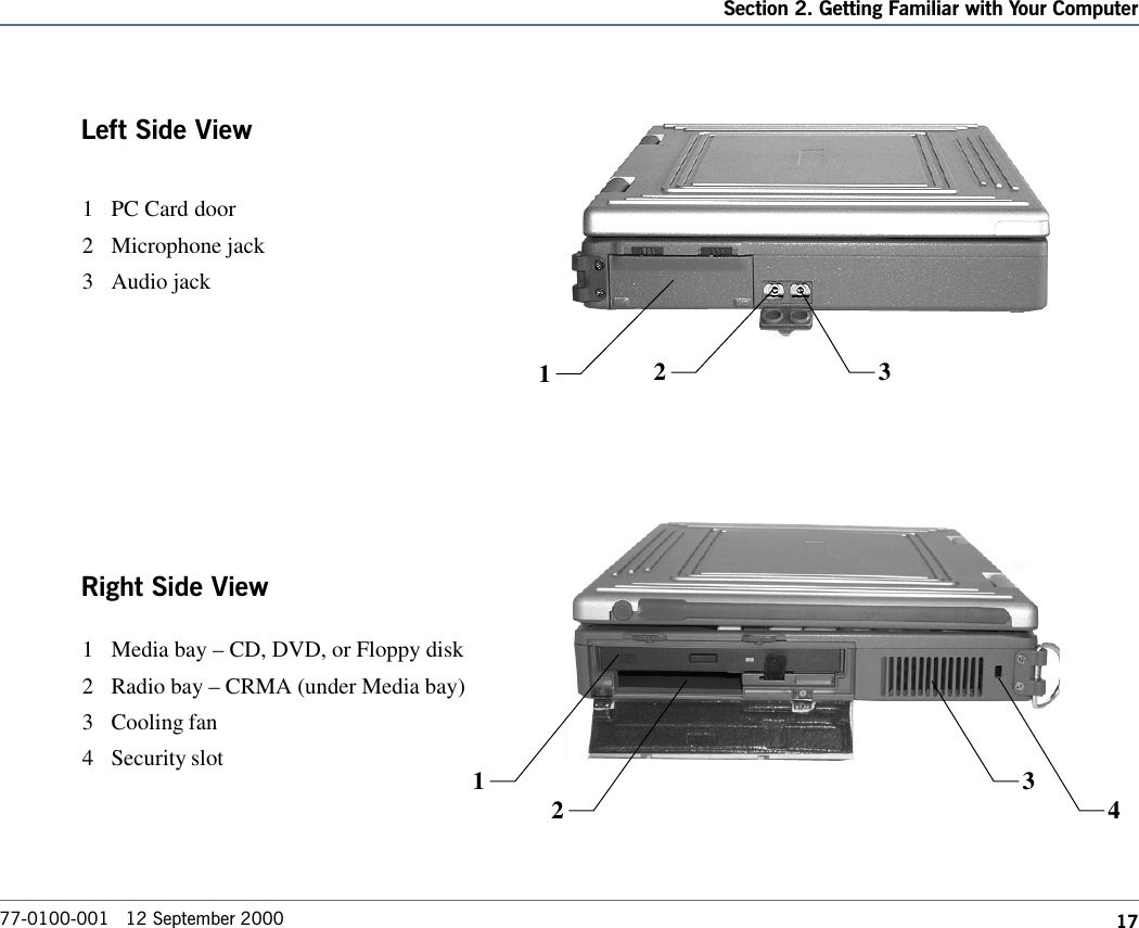
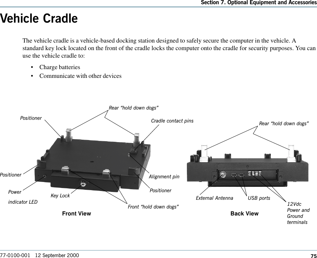
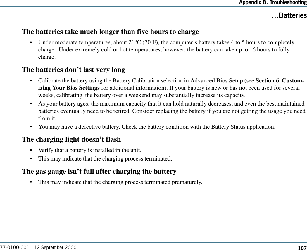
![77-0100-001 12 September 2000GoBook Users ManualviWarnings and CautionsWARNING It is important that only authorized Itronix personnel attempt repairs on Itronix equipment as this mightvoid any maintenance contract with your company. Unauthorized service personnel might be subject to shock hazardon some Itronix equipment if removal of protective covers is attempted.The product you have purchased is powered by a rechargeable battery. The battery is recyclable and, under variousstate and local laws, it may be illegal to dispose of this battery into the municipal waste stream. Do not crush thebattery or place it in a fire. Check with your local solid-waste officials for details on recycling options or properdisposal.CAUTION Internal components of the GoBook (IX250) computer will be damaged if exposed to contaminants.When dust covers, the PC card door, or the battery door are open on the computer, shield the unit from allcontaminants such as liquids, rain, snow, and dust.WARNING “In order to comply with the FCC RF exposure requirements this device must be operated with aminimum seperation distance of 4 cm between the user/nearby persons and the antenna in its intended verticaloperating position.” “The antenna location is fixed in the upper right edge of the display screen and is not to be relocated”“The equipment has been approved to [Commission Decision “CTR21”] for pan-European single terminal connec-tion to the Public Switched Telephone Network (PSTN). However, due to differences between individual PSTNsprovided in different countries the approval does not, of itself, give an unconditional assurance of successfuloperation on every PSTN network termination point.In the event of problems, you should contact your equipment supplier in the first instance.](https://usermanual.wiki/General-Dynamics-Itronix/IX250RIM902.Users-Manual/User-Guide-125327-Page-6.png)


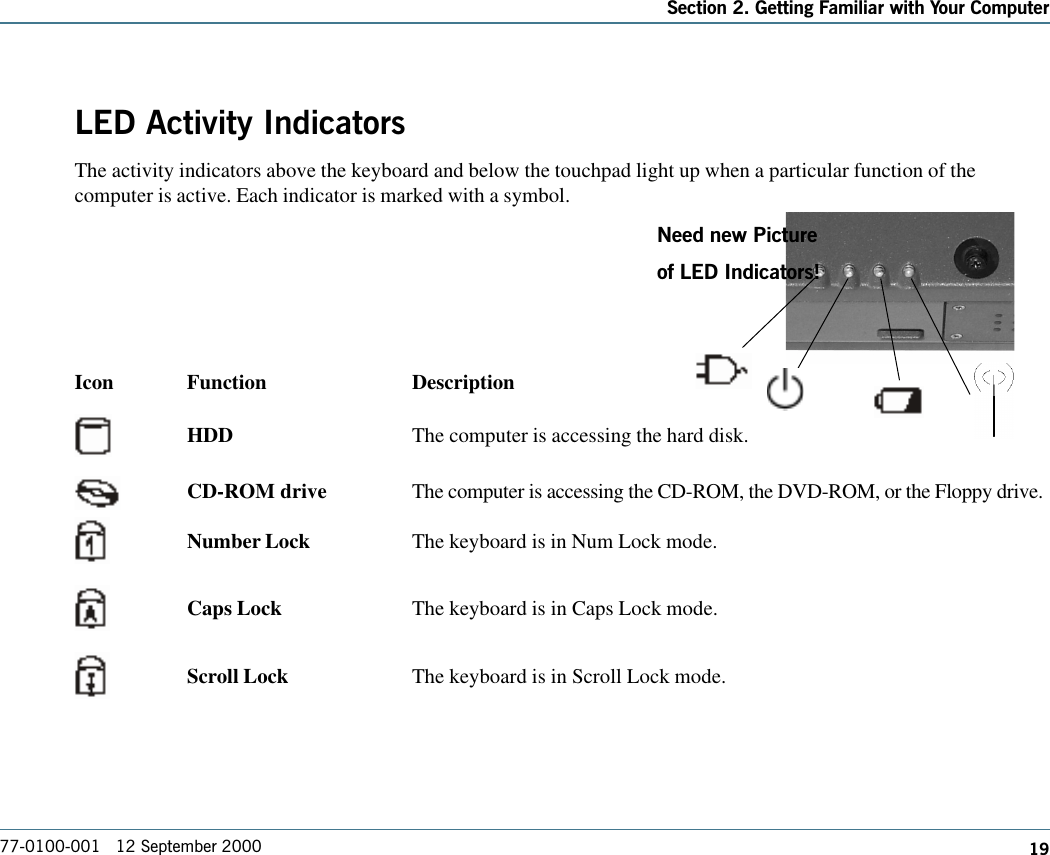


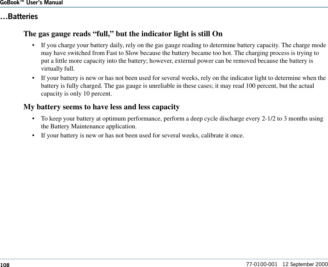
![110GoBook Users Manual77-0100-001 12 September 2000.DisplayThe underlined, inverse, and hypertext characters are difficult to read on the screen•Change the color scheme. From the Start Menu select Settings, Control Panel, choose Display, and then clickthe Appearance tab to make changes to the color scheme.•Make the online hypertext jumps black by adding the line JumpColor=0,0,0 to the [Windows Help] section ofWIN.INI.I can’t see the cursor while using the DOS editor•Press FN+INSERT to change from insert mode to overwrite mode to enable a block cursor. When it defaultsto insert mode, the DOS editor uses an underline cursor which is less visible than the block cursor for over-write mode.The display appears to have random pixels darkened after scrolling•Contact your supervisor or your organization’s help desk for information about correcting this problem.I changed my display resolution, but I see no difference on the screen•Try restarting your computer for the changes to take effect.](https://usermanual.wiki/General-Dynamics-Itronix/IX250RIM902.Users-Manual/User-Guide-125327-Page-124.png)
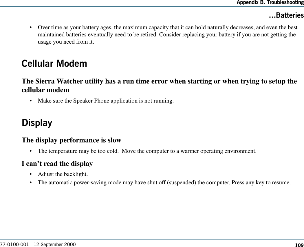
![122GoBook Users Manual77-0100-001 12 September 2000The system does not recognize the PC Card CD-ROM when it is inserted into the PC Cardsocket•There is a delay of 10 to 15 seconds before the CD-ROM drive is recognized.•Drivers may not be installed. Contact your organization’s help desk for assistance.The computer locks up when I remove the PC card•Before you remove the card, select the PC card icon in the system “tray” area of the screen (near the clock inthe lower right corner), and choose “Stop [card name] card.”](https://usermanual.wiki/General-Dynamics-Itronix/IX250RIM902.Users-Manual/User-Guide-125327-Page-136.png)