General Dynamics Itronix XC6250RIM801D Laptop PC with RIM 801D ARDIS Radio Module User Manual User Manal RIM Manual

General Dynamics Itronix Corporation Laptop PC with RIM 801D ARDIS Radio Module User Manal RIM Manual

Contents

User Manal (RIM Manual)
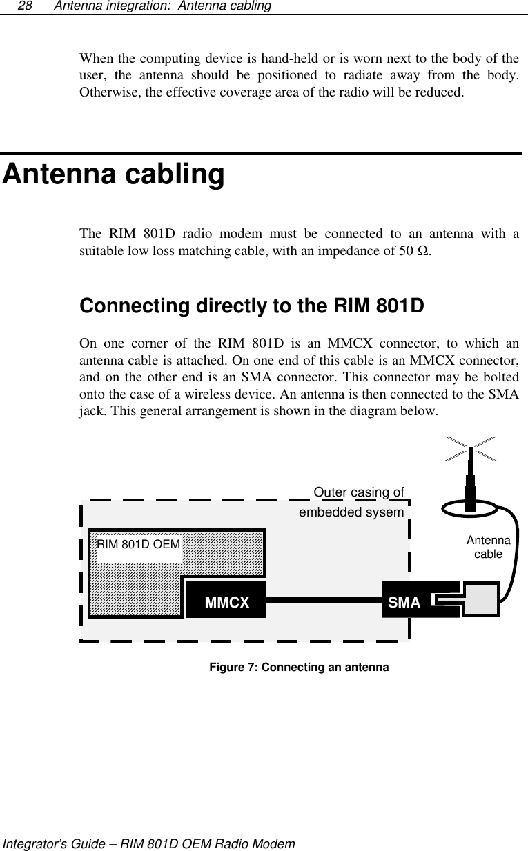
Integrator’sGuideRIM 801DOEM Radio Modemversion 1.0
RIM 801D OEM Radio Modem Integrator’s GuideLast Revised: 22 February 1999Part Number: MAT-01769-002 Rev. 001©1998, RESEARCH IN MOTION LIMITEDResearch In Motion and RIM are registered trademarks of Research In MotionLimited.DataTAC and RD-LAP are trademarks of Motorola.MS-DOS is a registered trademark, and Windows is a trademark, of MicrosoftCorporation.Velcro is a registered trademark of Velcro Canada Incorporated.Scotchmate and Dual Lock are trademarks of 3M Corporation.Warning: This document is for the use of licensed users only. Any unauthorizedcopying, distribution or disclosure of information is a violation of copyright laws.While every effort has been made to ensure technical accuracy, information in thisdocument is subject to change without notice and does not represent a commitmenton the part of Research In Motion Limited.Research In Motion295 Phillip StreetWaterloo, OntarioCanada N2L 3W8tel. (519) 888-7465fax (519) 888-6906Internet: info@rim.netWeb site: www.rim.netPrinted in Canada AM0598R801D-intDATATAC Interface, specifiedDataTAC Open ProtocolSpecification970.0775R1
FCC Compliance Statement (USA)FCC Class B Part 15This device complies with Part 15 of FCC Rules. Operation is subjectto the following two conditions:1. This device may not cause harmful interference, and2. This device must accept any interference received, includinginterference that may cause undesired operation.WarningChanges or modifications to this unit not expressly approved by theparty responsible for compliance could void the user’s authority tooperate this equipment.This equipment has been tested and found to comply with the limitsfor a Class B digital device, pursuant to Part 15 of the FCC Rules.These limits are designed to provide reasonable protection againstharmful interference in a residential installation. This equipmentgenerates, uses and can radiate radio frequency energy and, if notinstalled and used in accordance with the manufacturer’sinstructions, may cause harmful interference to radiocommunications.There is no guarantee, however, that interference will not occur in aparticular installation. If this equipment does cause harmfulinterference to radio or television reception, which can be determinedby turning the equipment off and on, the user is encouraged to try tocorrect the interference by one or more of the following measures:•  Re-orient or relocate the receiving antenna.•  Increase the separation between the equipment andreceiver.•  Connect the equipment into an outlet on a circuit differentfrom that to which the receiver is connected.Consult the dealer or an experienced radio/TV technician for help.
ContentsFCC Compliance Statement (USA)..........................................iFigures, tables and equations................................................. vAbout this guide.....................................................................vii1. Introduction................................................................. 1Radio modem features.....................................................................1DataTAC network technology.........................................................32. Mechanical specifications and mounting needs........ 5Environmental properties ................................................................5Physical properties ..........................................................................6Mounting the RIM 801D.................................................................83. Power requirements .................................................. 11Load specifications........................................................................11Automotive supplies......................................................................13Rechargeable batteries...................................................................13Single use batteries........................................................................14Plug-in supplies.............................................................................15Connecting the power source ........................................................164. Serial interface specification .................................... 17Signal specifications (Standard 5V interface) ...............................17Connecting the serial cable............................................................18Detailed pin description.................................................................19Turning the radio ON ....................................................................23Turning the radio OFF...................................................................235. Antenna integration .................................................. 25Antenna requirements....................................................................25Positioning the antenna..................................................................27Antenna cabling.............................................................................28Shielding........................................................................................30
6. Protocol support ........................................................ 33Service Data Units (SDUs)........................................................... 34NCL Protocol ............................................................................... 35Radio Access Protocol (RAP) ...................................................... 35Summary....................................................................................... 417. Interfacing and controlling the RIM 801D.............43Interfacing to an RS232 device..................................................... 43Controlling the RIM 801D ........................................................... 44Serial port interface ...................................................................... 44Specifications ......................................................................... 49Glossary of terms................................................................... 51Appendices............................................................................. 53Appendix I - Parts......................................................................... 53Appendix II - Company Directory................................................ 55Index....................................................................................... 57
Figures, tablesand equationsFigure 1: Top view of RIM 801D 7Figure 2: Side view of RIM 801D 7Figure 3: Battery Transmit Power Comparison 14Figure 4: Sample plug-in supply 15Figure 5: FPC cable and connectors 18Figure 6: Controlled Shutdown Using a Low-Power Battery Supply 24Figure 7: Connecting an antenna 28Figure 8: Different MMCX Connector Orientations 29Figure 9: Example SMA Jack Connectors 30Figure 10: RAP Frame Structure 37Figure 11: Sending data from the host to the wireless network 38Figure 12: Simple PC RS232 Interface 45Figure 13: Simple 8051 Interface 46Figure 14: 8250 Serial Port Interface 47Table 1: Serial Interface Pin-out and Description 19Equation 1: VSWR 26Equation 2: Return Loss 26
About this guideThis document is a guide to integrating the RIM 801D OEM DataTAC radiomodem into an embedded system, such as a laptop computer, PDA, vendingmachine, POS terminal, or alarm system.Topics covered in this guide include:•  physical size and mounting requirements•  power and battery characteristics•  interfacing to the RIM 801D•  antenna selection and placement•  communication protocolsThroughout the guide, there are suggestions and precautions that will easethe implementation of a wireless communication solution. Attention isdrawn to these through the use of the two symbols below.This symbol represents a hint or a suggestion. Although the ideas presentedare not necessary to the integration of the RIM 801D, they are useful tomany applications, and they may save integrators time.This is an important note or a warning. The text will advize integrators of apotentially hazardous situation, or a necessary precaution to take whendesigning applications.!
11. IntroductionTopics covered in this introduction include the RIM 801D OEM radiomodem features and an introduction to DataTAC network technology.Radio modem featuresThe RIM 801D OEM radio modem is specifically designed to integrateeasily into a computer or other embedded system, such as PDAs, vendingmachines, and point-of-sale terminals. Operating in the 800 MHz frequencyrange, the RIM 801D is compatible with DataTAC wide-area wireless datacommunication networks.Powerful and efficient transmitterThe RIM 801D provides reliable transmit efficiency throughout the range ofoperational voltage (6.0 to 9.5 volts). This is an important feature becausethe radio modem does not lose transmit power as battery voltage drops,thereby keeping the radio coverage area at a maximum throughout the life ofthe battery. The chart below shows how the transmit power output remainsconstant over the 6.0 to 9.5 volt supply.
Introduction: Radio modem featuresIntegrator’s Guide – RIM 801D OEM Radio Modem2Leveled Transmit PowerBattery Voltage [V]15.0018.0021.0024.0027.0030.0033.006.00 6.50 7.00 7.50 8.00 8.50 9.00Noise immunityThe RIM 801D is not de-sensitized by RF noise generated by nearbyelectronics. This makes the RIM 801D ideal for integration into hand-heldterminals, and eliminates the need for special shielding. Noise immunitysignificantly increases reliability, improves performance, extends batterylife, and increases the effective range of operation of the RIM 801D.Low power requirementsBattery life is a critical issue for portable devices: end-users want longlasting devices without heavy battery packs. The RIM 801D sets a newpower consumption standard for OEM-style radio modems by reducingstandby power to only 12 mA. This allows the RIM 801D to maximizeefficiency and ensure long battery life.Small sizeUsing a single board design, the RIM 801D is very thin, only 0.3” to 0.38”(7.5 to 9.6 mm). The RIM 801D is about the size of a credit card, with afootprint of 3.5” by 2.6” (87.5 by 66.3 mm). This tiny size makes the RIM801D very lightweight (only 2.3oz or 64g, including case) and allows thedevice to meet tight space requirements within most applications.
Introduction: DataTAC network technologyRIM 801D OEM Radio Modem – Integrator’s Guide3DataTAC network technologyThe DataTAC infrastructure has become an international datacommunications standard, offering fast data transmission rates withaccurate, highly reliable message delivery. DataTAC networks are deployedaround the world from North America to Europe to Asia-Pacific.Using an advanced Radio Data Link Access Procedure (RD-LAP) radiochannel protocol, DataTAC systems provide transmission rates up to 19.2kb per second and 9.6 kb per second depending on the country. Those ratesmean fewer delays and faster response times for the mobile user. Fornetwork operators, they mean greater capacity to accommodate morecustomers, while minimizing the required investment in networkinfrastructure.DataTAC’s error detection and correction schemes provide increasedmessage accuracy, fewer message retries and enhanced networksthroughput. With DataTAC technology, the state of the entire network isconstantly monitored and safety mechanisms including system alarms,remote diagnostics and redundant back-up links ensure network reliabilityand availability.The key components of the network infrastructure include the NetworkManagement Center (NMC), Area Communications Controller (ACC) andbase site equipment.The NMC is an advanced client-server based management tool whichprovides all network administration, operation and maintenance functions. Itacts as the central point of control in the DataTAC system.The ACC consists of the Radio Network Gateway (RNG), Radio NetworkController (RNC), and Communications Hub. The ACC is primarilyresponsible for all message switching and routing functions, as well asproviding the key communication link between host computers and remotebase stations. Connectivity between the host computer and the infrastructureis established using industry standard X.25 or TCP/IP host link protocols.The ACC maintains all customer-specific information for each device on thesystem and allows users within a given geographic area to connect to hostapplication services. It manages user device authorization, roaming controland base site control. It also collects all system usage/traffic information foraccounting/billing purposes and detailed analysis of usage patterns.
Introduction: DataTAC network technologyIntegrator’s Guide – RIM 801D OEM Radio Modem4DataTAC Data System Station (DSS) base site equipment is located atvarious remote sites in the operational area of coverage and provides the RFlink between the DataTAC infrastructure and end user devices. They convertthe host data messages into the RD-LAP radio channel protocol fortransmission to the user devices and reverse the process on the returnconnection. They also allow device roaming between base site coverageareas in a seamless manner completely transparent to the end user.
22. Mechanicalspecifications andmounting needsThis chapter provides information about the RIM 801D that will be useful indetermining the physical positioning of the radio modem within anapplication. Environmental properties, case dimensions, cabling, connectors,and mounting suggestions are presented.Environmental propertiesThe RIM 801D OEM Radio Modem is designed to function within thefollowing environmental limits:•  -30°Cto+55°C(-22°F to +131°F) operational•  -40°Cto+85°C(-40°F to +185°F) storage•  5 to 95% relative humidity, non-condensing
Mechanical specifications and mounting needs: Physical propertiesIntegrator’s Guide – RIM 801D OEM Radio Modem6Physical propertiesDimensionsThe RIM 801D has been designed to meet the most stringent spacerequirements. In most cases, there will be sufficient room in an existingenclosure to house the radio modem. Within the case of the modem, thesmaller components are mounted on one side, and the larger components onthe other. This separation of large and small components results in a casewith two different thickness (see Figure 2, below).The overall maximum dimensions of the radio modem are:•  Width: 2.61” (6.63 cm)•  Length: 3.44” (8.74 cm)•  Thickness: 0.30” (0.75 cm) to 0.38” (0.96 cm)Top and side views of the radio modem are shown on the next page.WeightThe RIM 801D weighs 2.3oz (64g), including the case.
Mechanical specifications and mounting needs: Physical propertiesRIM 801D OEM Radio Modem – Integrator’s Guide7Figure 1: Top view of RIM 801DFigure 2: Side view of RIM 801D
Mechanical specifications and mounting needs: Mounting the RIM 801DIntegrator’s Guide – RIM 801D OEM Radio Modem8Mounting the RIM 801DThe RIM 801D OEM radio modem may be securely fastened using a varietyof methods. When deciding on a mounting option, the most importantconsideration is the operating environment. Such factors as extremetemperature or heavy vibration may dictate the need for a special mountingsolution.Due to the RIM 801D’s small size and low weight, Research In Motionrecommends the use of an industrial adhesive when attaching the radiomodem to the host device. This method of mounting is preferable to bolts,because of its ease of use in manufacturing and its resistance to loosening.An effective solution is to adhere the radio modem to the inside surface ofyour product’s casing.The designer should select an adhesive based on its suitability to themounting surface of the radio modem as well as the casing. The outer casingof the RIM 801D is pre-tinned steel or stainless steel, with a thickness of0.010” (0.25 mm).The following information is presented as a guide, but applications can varyconsiderably. Please make sure that the mounting method you choose issuitable for your particular application.Permanent adhesive3M manufactures VHB, a permanent industrial adhesive with excellentlong-term holding power. The peel adhesion and tensile holding power ofVHB tapes are extremely high, making this a suitable solution when theradio will not need to be removed.Testing by Research In Motion has shown that a RIM 801D radio modem,bonded to a suitable surface with VHB, should never come loose even whensubject to heavy vibration. Although the use of an adhesive might seeminadequate or insufficient, it should be considered that this particularadhesive is extremely strong — for example, VHB tapes replace rivets infastening side panels to the frames of ambulances. VHB adheres best tometal, and can also be used on finished wood, paper, cardboard, glass,painted concrete, and most plastics, with various ratings in bond strength.VHB will not bond to polyethylene or polypropylene plastics, leather, orfabric.
Mechanical specifications and mounting needs: Mounting the RIM 801DRIM 801D OEM Radio Modem – Integrator’s Guide9Please be aware that because VHB is a permanent adhesive, the radiomodem cannot be removed once it is installed. Attempting to break theadhesive bond by twisting off the radio modem will certainly damage theunit. There is no known solvent that will remove VHB. If using VHB as youradhesive, please make sure that you will not need to remove the radiomodem after it is installed. Otherwise, the use of a reclosable fastener isrecommended.More information about VHB may be obtained by contacting 3M IndustrialTape and Specialties Division. The publication number for the VHBtechnical data sheet is 70-0702-0266-1(104.5)R1. Please refer to -Appendix II for complete contact information.Reclosable FastenersA reclosable fastener may be used to affix the RIM 801D to a surface. Theuse of such fasteners is useful if the radio modem might be removed at somepoint during the product’s life. For example, the RIM 801D can be installedin a housing with no need for the end user to remove the radio modem, butthe product manufacturer might later wish to do so.The choice of reclosable fastener is governed by two factors. The first is thestrength of the closure. The fastener should ensure that the closure will lastlong enough so the radio modem will not accidentally separate from thehousing of the embedded system. The second consideration is the number oftimes the radio modem will be removed and refastened.Two lines of Velcro-like reclosable fasteners are offered by 3M: Scotchmateand Dual Lock. Scotchmate is a plastic hook and cloth loop fasteningsystem, the use of which is inappropriate to this application because it isexpected that the radio modem would eventually come loose. Dual Lock is asturdier, more rugged design that is appropriate to this task. The use of DualLock, alone or in combination with Scotchmate, offers excellent fasteningwhile retaining the capability of removing the RIM 801D.Different applications have different fastening needs. The combinationssuitable to most applications are outlined below:•  Attaching the RIM 801D to a rigid surface. The use of Type 400Dual Lock with Type 170 Dual Lock is a universal combination,suitable for most situations where the RIM 801D is affixed to arigid surface. (The “Type” number, 400 or 170, refers to thenumber of interlocking mushroom-shaped stems per square inch.)
Mechanical specifications and mounting needs: Mounting the RIM 801DIntegrator’s Guide – RIM 801D OEM Radio Modem10The RIM 801D can be removed and reattached as often asnecessary using this method.•  Attaching the RIM 801D to a flexible surface. Using Type 400Dual Lock on both surfaces offers the maximum tensiledisengagement of 55 psi (380 kPa). The RIM 801D can beremoved and reattached as often as necessary using this method.•  Maximum holding power. A high-strength closure may beobtained by mating Scotchmate Loop (on the RIM 801D) withType 170 Dual Lock (on the attaching surface). The peel strengthof this combination is very high, at 10 pounds/inch (17.5 N/cm).This solution offers the highest possible long-term holdingstrength, but it limits the number of times the RIM 801D could beremoved to between 20 and 50. Please be aware that the radiomodem may tend to “wiggle” a little bit because of the loops. Thismay give the appearance of a loose bond, although the radio is infact held in place quite securely.It is necessary to choose the adhesive backing on the fastener strips (rubberadhesive, acrylic adhesive, or VHB) so that it is appropriate to the attachingsurface. Either backing will attach to the RIM 801D’s steel casing, althoughVHB is recommended for its greater strength. However, VHB will notadhere to polyethylene or polypropylene plastic, for which rubber adhesiveis recommended.The disadvantage of these reclosable fasteners is that they will add slightlyto the thickness of the radio modem. The engaged thickness of thecombinations above will be from 0.19” to 0.23” (4.8 mm to 5.8 mm).More information about 3M’s reclosable fasteners may be obtained bycontacting 3M Industrial Tape and Specialties Division and requestingpublication number 70-0704-5609-3(833)JR.Other solutionsYou may determine that other mounting solutions — such as cable, twist tiesor brackets — are more effective for your particular application. In all cases,it will be important to ensure that the RIM 801D OEM radio modemremains securely attached, even when subject to the most extreme vibrationand temperature anticipated in the operating environment.
33. Power requirementsThe RIM 801D OEM Radio Modem must be provided with a clean, highcurrent power source. This can be provided by a plug-in power supply unit,a rechargeable battery pack, or single use batteries. RIM has conductedextensive research and has developed guidelines for integrators to followwhen designing the power supply system for the RIM 801D OEM RadioModem.Care should be taken when supplying power to the RIM 801D. Connectingwith the wrong polarity will damage the radio. We recommend protectingthe radio from reverse polarity by attaching a Schottky diode in series withthe Radio Modem’s power cable if there is any danger of reverseconnection. A 1N5822 is suitable for this purpose.Load specificationsThe RIM 801D OEM Radio Modem draws its power in bursts; the powerrequired can change rapidly as it begins or ends a transmission. The loadprofile is given on the following page. These specifications should be usedwhen choosing the battery or power supply system for your application.They can be given directly to your power supply designer or batterysupplier. Please note that these specifications are subject to change withoutnotice.!
Power requirements: Load specificationsIntegrator’s Guide – RIM 801D OEM Radio Modem12Power DesignMaximum voltage without damage 10.5 VoltsMaximum operating voltage 9.5 VoltsMinimum operating voltage 6.0 VoltsMaximum current (at 7.2V) 1.3 AmpsRecommended fuse size (external) 3.0 AmpsTotal supply impedance recommended(external) 1.5 Ω(max)Recommended operating voltage range 7.0 to 9.0 VoltsLoad ProfileExpress mode (typical) 60 mAStandby mode (typical) 12 mATransmit current draintypical (1.5 W to antenna)peak instantaneous 900 mA1.25 ABattery saving mode (typical)(1% Tx, 5% Rx, 94% Standby) 24 mATransmit durationminimummaximum 21 ms (RD-LAP@19200)1.1 seconds (MDC)Ramp up time(from Continuous to Transmitting) 1msRamp down time(from Transmitting to Continuous) 1msOff current consumption (typical) ≤100 µA
Power requirements: Automotive suppliesRIM 801D OEM Radio Modem – Integrator’s Guide13Automotive suppliesIf you plan to power the RIM 801D from an automotive supply, extraprotection must be included to protect the radio modem from the intensepower fluctuations experienced when the automobile is started. A circuitcomprising inductors, transorbs and voltage regulators should be used toensure the radio modem is protected from these power fluctuations.Commonly, in automotive applications, voltages may be as high as seventyvolts on the battery, especially during starting. Commercial automotiveadapters are available that will safely convert the 12 volt automotive supplyto a regulated 8 volt supply suitable for operating the RIM 801D radiomodem.Supplying the RIM 801D with more than 10.5 volts will damage themodem.Rechargeable batteriesFor battery-operated applications requiring a wide operating temperature,RIM recommends using Nickel-Cadmium (NiCad) batteries to power theradio unit. Nickel-Metal-Hydride and Lithium Ion cells may also be used,but the cell temperature specifications may inhibit operation at temperaturesbelow freezing.The cells chosen should be able to meet the load specifications of the RIM801D. RIM has found that a six-cell AA NiCad battery pack provides agood balance of size and performance. For space-restricted designs, AAANiCad cells will require about one-third the volume, but provide only aboutone-fifth of the transmit time.Using cells smaller than AAA is not recommended, as these cells do notgenerally have the capacity to sustain a high rate of transmission.
Power requirements: Single use batteriesIntegrator’s Guide – RIM 801D OEM Radio Modem14Single use batteriesWhen using single use cells, RIM has found that only Alkaline cells providethe high current necessary for transmission. AA, AAA, and even square 9Volt batteries provide an excellent power source. The following graph wasgenerated by a simulator, not an actual radio modem; it depicts the varioustransmit capacities of some standard “off the shelf” batteries. The transmitcurrent used for these tests was 1.25 Amps. In normal operation, thetransmitter will draw less than 1 Amp average.Number of 1 Second (1 Kbyte) Transmit Cycles Before 6.0V CuttoffCycles050010001500200025006-AANiCd(MPTPack )6-AAAAlkPrim ary6-AAANiCd 9V AlkPrim ary 6-1/3AANiCd9VNiCd 9VCarbonPrimaryFigure 3: Battery Transmit Power ComparisonClearly, AA batteries provide the best transmission capacity. Note thatalkaline batteries are not efficient at high currents, which causes theirtransmit capacity to be smaller than expected, but still better than NiCad.The use of general-purpose carbon-based batteries is not recommended, asthe power supplied will drop to below the minimum required almostimmediately.
Power requirements: Plug-in suppliesRIM 801D OEM Radio Modem – Integrator’s Guide15Plug-in suppliesA plug-in supply converts normal AC power (usually 110 volts or 220 volts)into a steady DC source that can be used instead of batteries. The plug-insupply must be designed to ensure voltage spikes, lightning, and otherpower fluctuations cannot damage the radio modem.RIM recommends a supply capable of providing 8 volts and 1.5 amps peakcurrent. This can be accomplished by employing a 12 volt 1.5 amp peak (1.0amp continuous) unregulated power source, and adding an 8 volt regulator(such as an LM7808).The schematic drawing for a sample plug-in supply is provided below. Thiscircuit provides 8 volts DC to operate the RIM 801D, as well as 5 volts forthe embedded system VCC. Please note that it is not necessary to supply theRIM 801D with a 5 volt VCC — there is only one power source to the radiomodem, and that is the 8 volt supply.Figure 4: Sample plug-in supply
Power requirements: Connecting the power sourceIntegrator’s Guide – RIM 801D OEM Radio Modem16Transient voltage protection zener diodes, or other spike arrestor circuits,should also be added to keep the inputs within the limits given in the RIM801D load specifications. These should have a value of 20 volts and beplaced on the supply side of the regulator circuit.Connecting the power sourceWhatever the power source, it must be connected to the RIM 801D throughthe power input pins on the side of the radio modem. The mating connectoris a Molex 51005-0200, 2.00 mm (0.079”) wire-to-board housing, plus twopieces per modem of Molex 50011-8100 wire-to-board 3/32” crimpterminal. (Please see page 54 for more information.) This will connect totwo 24 gauge supply wires in your system.
44. Serial interfacespecificationThe serial interface on the RIM 801D operates at HCMOS electrical levels.This interface can be connected directly to a micro-controller, or through aUART to a microprocessor data bus.Signal specifications (Standard 5V interface)OutputsOutput High Voltage @ 10µA4.5 Volts Min.Output Low Voltage @ -10µA0.4 Volts Max.Short Circuit Current 24 mA Max.Recommended Output Capacitance(To Filter Interface Lines) 390 pFInputsInput High Voltage 3.5 Volts Min.
Serial interface specification: Connecting the serial cableIntegrator’s Guide – RIM 801D OEM Radio Modem18Input Low Voltage 1.5 Volts Max.Input Leakage Current High 1.0 µAInput Leakage Current Low -1.0 µAThe RIM 801D can also be customized for 3.3 volts.Connecting the serial cableThe RIM 801D serial communication and power on/off signals are carriedon a flat 14-conductor flexible printed circuit (FPC) cable, which can pluginto a matching connector.An appropriate 4” 14-pin cable is available from Molex Canada, partnumber 88-00-8025. Different lengths and orientations are also available.The cable can plug into a matching connector such as an AMP 1.0 [0.039]FPC connector, surface mount, model 1-487951-4 (Please see -Appendix II for contact information)Example pictures of the FPC cable and connectors are shown below:Figure 5: FPC cable and connectors
Serial interface specification: Detailed pin descriptionRIM 801D OEM Radio Modem – Integrator’s Guide19Detailed pin descriptionThis section describes the purpose of each of the 14 lines that comprise theserial interface of the RIM 801D OEM radio modem.Note that any unused inputs should be tied to ground (with the exception ofDNC1 and DNC2).Pin Label Source Active Description1 DNC1 RAD Do not connect to VCC or GND2 RX Radio Serial Data output from Radio to Host3 TX Terminal Serial Data input to the Radio from Host4 DTR Terminal Low Data Terminal Ready input to Radio from Host5 SG N/A Signal Ground (Internally connected to Pin 14)6 DSR Radio Low Data Set Ready output from Radio to Host(Internally connected to PIN 4)7 RTS Terminal Low Request to Send input to Radio from Host8 CTS Radio Low Clear to Send output from Radio to Host9 RI Radio Low Ring Indicator output from Radio to Host10 DNC2 Terminal Do not connect to VCC or GND11 TRI Radio High Transmit Indicator Output from Radio to Host12 ONI Radio High On Indicator Output from Radio to Host13 TURNON Terminal High Turn On input to Radio from Host14 SG N/A Signal Ground (Internally connected to Pin 5)Table 1: Serial Interface Pin-out and DescriptionDNC1 and DNC2These are “Do Not Connect” pins. They are used for internal testing ofthe Radio hardware by RIM. Connecting these pins to VCC or Ground candamage the radio. Simply leave these pins disconnected when integratingthe radio modem into your device.!
Serial interface specification: Detailed pin descriptionIntegrator’s Guide – RIM 801D OEM Radio Modem20RXReceive is an output from the radio unit to the host terminal’s Receive input.This is a TTL/CMOS compatible output that is short-circuit protected. Thisline can be connected directly to the input of almost any asynchronouscommunications IC.This line has an impedance of 1 kΩand will be low when the radio unit isoff. The idle (no data) state of this line is high.TXTransmit is an asynchronous serial input to the radio unit, and can beconnected directly to the output of almost any asynchronouscommunications IC. This line must be driven by a source with an impedanceof 20 kΩor lower for operation at high baud rates.This line is held low through a 20 kΩresistor when the radio is off. The idle(no data) state of this line is high.DTRData Terminal Ready is an input to the radio unit and is used to signal thatthe Host terminal is ready. When the radio is on, asserting this line low willcause DSR to also go low, and will allow communication to take place.Asserting this line high will turn communications off, and will cause DSR togo high.DTR should be driven low when the radio is off. Driving DTR high whenthe radio is off can cause improper operation, may cause DSR to changestate to an indeterminate value, and will consume unnecessary power.SGSignal Ground should be tied to the system ground of the host unit. Theradio must also be grounded with the main power cable to assure properoperation .
Serial interface specification: Detailed pin descriptionRIM 801D OEM Radio Modem – Integrator’s Guide21DSRData Set Ready is an output from the radio unit. This signal is electricallyconnected to the DTR input and will therefore have the same properties asthe Host’s DTR output.When the Radio unit is off, this line will be low from inside the radiomodem with an impedance of at least 20 kΩ.RTSRequest To Send is an input to the Radio unit from the host. This lineshould be asserted low by the host to indicate that data is waiting to be sent.CTSClear To Send is an output from the Radio unit that indicates it is ready toreceive data from the Host. When this line is high any data sent from theHost to the Radio may be lost.This line will be low from inside the radio modem with an impedance of atleast 20 kΩ.RIRing Indicator is an output from the Radio that can be used to wake up asleeping Host system. If the radio is flow controlled off (DTR or RTSasserted high) and the Radio receives a packet, it will assert RI low to alertthe Host system that there is a data packet waiting.This line is low when the radio is powered off, and has a source impedanceof 21 kΩ(when high) or 1 kΩ(when low).TRITransmit Indicator is an output from the radio that is asserted highwhenever the Radio is transmitting a packet. This line can be used asfeedback to the host to ensure the radio is transmitting packets, or it can
Serial interface specification: Detailed pin descriptionIntegrator’s Guide – RIM 801D OEM Radio Modem22simply be left disconnected. This line has a built in current limit that allowsit to drive an LED directly as visual feedback for a user.This line will supply 3 mA to a standard LED, and is short-circuit protected.This line is low when the Radio is off.ONION Indication is an output from the radio that indicates when the radio ison and operational. This line should be used by a host system to qualify thehandshaking outputs on the serial interface. If CTS is low, and ONI is high,then the unit is ready to receive data, but if CTS is low and ONI is low, thenthe radio is not ready to receive data because it is off.When ONI is low, all inputs to the radio should be held low or disconnectedto assure the unit power consumption is minimized.ONI has an output impedance of 1 kΩ.TURNONThis input turns on the radio unit – a TTL and CMOS compatible signal.This pin’s electrical characteristics are different from the others, as shown inthe table below.Input High Voltage 2.5 Volts Min.Input Low Voltage 0.8 Volts Max.Input Leakage Current High 500 µAMax.Input Leakage Current Low -50 µAMax.Due to the higher current requirements of this pin, a direct drive CMOS orTTL output must be used. An open-collector output could also be used,provided it is pulled up by a 10 kΩresistor or smaller.
Serial interface specification: Turning the radio ONRIM 801D OEM Radio Modem – Integrator’s Guide23Turning the radio ONTo turn on the RIM 801D, the software should first check the ONI pin. IfONI is high, but TURNON is being held low, then the radio is currentlyperforming shutdown operations and should not be disturbed. Wait for ONIto go low before continuing.If ONI is low, this indicates the radio is in the off state. Set the TURNONline high to activate the unit. The ONI pin will respond by going high from100 - 500 ms later. Once the ONI pin is high, other handshaking andcommunication signals can begin.If the radio does not respond to the TURNON signal within 1 second, theTURNON line should be de-asserted. Another TURNON cycle should thenbe attempted. If the radio still fails to respond, the radio may require service,or the battery may be too low for proper operation.Turning the radio OFFTo turn the RIM 801D off, the software should de-assert the TURNON lineby setting it low. The radio will then begin shutdown operations. All inputsto the radio should also be set low. The ONI pin will remain active until allshutdown operations are complete. Attempting to communicate with theRadio during shutdown may extend the time taken to perform shutdownoperations.Shutdown will normally require several seconds to complete. Uponcompletion the ONI signal will be de-asserted (low). All inputs to the radiomust now be set low, if they are not already low. This ensures that powerconsumption will be reduced to the lowest possible levels. Note that if anyline is left in the high state, as much as 5 mA may flow into the radiomodem.Flow control inputs that are not used may be tied to ground. This ensuresthat they will be asserted during radio operation.SDUs (Service Data Units) which have been received over the DataTACnetwork to radio link, but which have not been transferred across the radio
Serial interface specification: Turning the radio OFFIntegrator’s Guide – RIM 801D OEM Radio Modem24modem to terminal link, will not be saved. The SDU will be lost when theunit enters shutdown or is turned off.A controlled shutdown is necessary to allow the RIM 801D to tell theDataTAC network that it is off air. The following schematic offers a low-power shutdown circuit, together with an example of using a 6-AA NiCadrechargeable battery pack to power the RIM 801D.Please note that in the following circuit, the signals marked Shutdown andTurnoff are not connected to the RIM 801D radio modem, but to theprocessor of the embedded system. If no processor is present, the Turnoffline can be tied to the RIM 801D’s Turnon,andtheShutdown signal can betied to the RIM 801D’s ONI line.The ON button forces the system to turn on. The processor then sets the SHUTDOWN linehigh. When the button is released the system stays on.The OFF button sends a request to the processor to shutdown. The processor will thenset the SHUTDOWN line low after the radio has been shutdown.If no processor is present, the TURNOFF signal can be tied to TURNON and SHUTDOWN canbe tied to ONI of the RIM 801D radio.Figure 6: Controlled Shutdown Using a Low-Power Battery Supply!
55. Antenna integrationThe choice of antenna is important to maximizing the coverage area of theRIM 801D radio modem. It is important to choose an antenna that will bestcompliment the needs of a specific project. There are many differentantenna options that will meet both your gain and directivity requirementsand remain within budget constraints. Three well-known antennamanufacturers that have experience with DataTAC frequencies are Larsen,Austin Antenna and Antenna Technology Inc. (Please see -Appendix II for contact information). Research In Motion Limited can alsoprovide antenna design services.Antenna requirementsThe RIM 801D OEM Radio Modem transmits on frequencies between806 MHz to 825 MHz. Receive frequencies are between 851 MHz and870 MHz.Antenna gainAntenna gain is dependent on the radiation pattern, antenna match, andantenna efficiency. Antenna gain is a rating of the maximum increase inradiated field energy density relative to an ideal isotropic radiator,expressed in decibels (dB) of power gain.An isotropic radiator is an unrealisable theoretical reference for measuringantenna gains and patterns. It is based on a 100% efficient point source
Antenna integration: Antenna requirementsIntegrator’s Guide – RIM 801D OEM Radio Modem26radiator with a spherical radiation pattern. That is, the field energy density isidentical in any direction from the radiator at each fixed distance from theradiator.Antennas produce gain by concentrating radiated energy in certain areas,and radiating less energy in other directions.Antenna matchAntenna match is related to the Voltage Standing Wave Ratio (VSWR), aratio of incident and reflected power due to impedance mismatch andantenna efficiency. Impedance mismatches can be due to cable connections,cable lengths, and imperfections in the cables and connectors. The mismatchcauses some of the radio frequency energy to be reflected back from thelocation of the mismatch, which interferes with the signal and reduces itsamplitude, resulting in a power loss.VSWR =+1PP1- PPreflectedoutputreflectedoutputEquation 1: VSWRAntenna mismatch can be expressed as a Return Loss (RL): a 10 xlog10 ofthe ratio of reflected power to the incident power.RL =× 10 10log PPreflectedoutputEquation 2: Return LossThe antenna match for “best performance” is a VSWR ≤1.5 or a RL < -14dB.The antenna match which is the minimum acceptable for the RIM 801D is aVSWR ≤2.0 or a RL < -10 dB.
Interfacing and Controlling the RIM 801D Antenna integration: Positioning the antenna 27RIM 801D OEM Radio Modem – Integrator’s GuideAntenna efficiencyThe optimal antenna radiation efficiency is produced by a monopole. Thebest antenna length is the length of the wavelength, λ. Where f is the radiofrequency being used, λ=c/f ≈3x10⁸/f(metres).Antenna lengths of λ/2, λ/4 or λ/8 also work well and usually result in arelatively well matched antenna. λ/2 or λ/4 can be electrically “shortened”by adding load matching elements to control the antenna match. However,this shortening will reduce the antenna efficiency and therefore the effectiveradiated power.RIM recommends the use of an experienced antenna provider in order torealize the highest gain possible. A well-designed antenna solution willmaximize efficiency, coverage area, and battery life.Positioning the antennaProper positioning of the antenna will maximize the gain provided by theantenna. In determining the “proper position,” the designer must carefullyconsider the environment in which the device will be used. There is nosingle “correct answer,” as embedded systems can vary significantly.Incorporating the antenna is an integral part of a successful design.The DataTAC network is based on vertically polarized radio-frequencytransmission. Therefore, the antenna should ideally be oriented so that itprovides vertical polarisation. This is achieved by positioning the antennavertically upward when the RIM 801D is in use. In small, hand-helddevices, it may be convenient to design the unit in such a way that theantenna folds out of the way when not in use.The antenna should be located as far from the active electronics of thecomputing device as possible. Metal construction in the case of thecomputing device and its internal components may attenuate the signal incertain directions. This is not desirable, as it would reduce the sensitivityand transmit performance of the radio modem.If the computing device is designed to sit on a surface, then the antennashould be as far from the bottom of the device as possible. This will reduceRF reflections whenever the device is placed on a metal surface.
Antenna integration: Antenna cablingIntegrator’s Guide – RIM 801D OEM Radio Modem28When the computing device is hand-held or is worn next to the body of theuser, the antenna should be positioned to radiate away from the body.Otherwise, the effective coverage area of the radio will be reduced.Antenna cablingThe RIM 801D radio modem must be connected to an antenna with asuitable low loss matching cable, with an impedance of 50 Ω.Connecting directly to the RIM 801DOn one corner of the RIM 801D is an MMCX connector, to which anantenna cable is attached. On one end of this cable is an MMCX connector,and on the other end is an SMA connector. This connector may be boltedonto the case of a wireless device. An antenna is then connected to the SMAjack. This general arrangement is shown in the diagram below.RIM 801D OEMMMCX SMAOuter casing ofembedded sysemAntennacableFigure 7: Connecting an antenna
Interfacing and Controlling the RIM 801D Antenna integration: Antenna cabling 29RIM 801D OEM Radio Modem – Integrator’s GuideFigure 8: Different MMCX Connector OrientationsThere are many orientation options available when connecting your antennacabling to the RIM 801D. Figure 8 shows the top-view (as shown in Figure1) of the antenna corner. The RIM 801D is available with one of threedifferent connectors: A) the right-angle, end-mount MMCX connector; B)the right-angle, side-mount MMCX connector and C) the straight, verticalMMCX connector.Different orientations give you more options when positioning the modem inthe terminal. The Straight and/or right-angled MMCX connectors can alsobe ordered with, or separately from antenna cabling. The combinations ofMMCX connectors of both the antenna cabling and the RIM 801D allowmany different positions. For example, an antenna cable with a straightMMCX connector can be fixed to point directly out from the RIM 801D inthe direction of the different modem connectors (see Figure 8), or anantenna cable with a right-angle MMCX connector can be fixed to the RIM801D to allow the cable to rotate 360ºalong the face, long, or short side ofthe RIM 801D.Huber & Suner can provide an 8” cable assembly. A suitable cable is theEZ Flex 405. The part number for this cable with a straight MMCXconnector is Huber & Suner Canada Part #: 133REEZ4-12-S2/1699 Length203mm. The cable is also available with a right-angle MMCX connectorPart #: 133REEZ4-12-S2/1699. Alternately, the connectors and cable can bepurchased individually. The SMA connector’s part number is 25SMA-50-2-25/111. The straight and right-angle MMCX connector’s part numbers arePart #: 11MMCX-50-2-1C/111 and Part #: 16MMCX-50-2-1C/111,respectively. Less expensive, but lower performance cable assemblies canalso be purchased. Please contact RIM for details. The cable should be builtwith strain reliefs to prevent damage.Other SMA jack connectors are the M/ACOM OSM (SMA) for flexiblecable, (A) Straight Cable Jack part number 2032-5007-02 (RG 142), (B)Bulkhead Feedthrough Cable Jack part number 2034-5004-02 (RG 142), orACBRIM 801D Antenna Corner (Top-View)
Antenna integration: ShieldingIntegrator’s Guide – RIM 801D OEM Radio Modem30(C) Flange Mount Cable Jack part number 2036-5003-02 (RG 142).Pictures of these three are shown below. Please refer to -Appendix II for contact information for both M/ACOM and Huber&Suner.(B)(A) (C)Figure 9: Example SMA Jack ConnectorsRIM offers a comprehensive Developer’s Kit for the RIM 801D to assistsystem designers. Included in the kit is a 50 Ωantenna cable. This cable hasbeen matched to the radio modem and may be directly connected to asuitable antenna, such as the 6 dB Magmount antenna that is optionallyincluded with the kit.For best results, the antenna should be connected directly to the antennacable. If an extension cable is required, it should be low loss, as short aspossible, and have an impedance of 50 Ω. It is important that a propermatching connector be used, as each connector in the signal path introducesa return loss, thereby reducing performance.If the device will be used in vehicles, then it should be provided with aconnector which allows the user to attach the antenna directly to the case, orto attach a cable which leads to an antenna mounted on the exterior of thevehicle.ShieldingThe RIM 801D is designed to provide high immunity to RF noise;consequently, it will not be necessary to provide special shielding. In fact, itis more important that the power supply to the RIM 801D be free of high-
Interfacing and Controlling the RIM 801D Antenna integration: Shielding 31RIM 801D OEM Radio Modem – Integrator’s Guidefrequency electrical noise, than to provide additional RF shielding betweenother computing devices and the RIM 801D case.The RIM 801D case provides shielding to prevent it from being affected byRF interference from the computing device to which it is attached. The casealso prevents the RIM 801D from emitting RF energy into the computingdevice and disrupting the computing device’s operation.The antenna must be positioned in such a way that the radiated energy isdirected away from the computing device. If this is not possible, then RFshielding may be required between the antenna and the computing device.Circuits with a high impedance and sensitive analog circuits are especiallyvulnerable to nearby radio frequency emissions, and may need to beshielded. Typically affected circuits include CRTs and LCD display drivers.!
66.Protocol supportThe RIM 801D OEM radio modem offers two link-level protocols: NCL(Native Control Language) and RAP (Radio Access Protocol). Bothprotocols serve the same function: they control the exchange of DataTACdata packets and radio control commands between the radio modem and thehost device.RAP offers several advantages over NCL when used with the RIM 801D, orother applications where the radio modem is physically located close to thehost device. RAP is a scaleable protocol that is easy to implement, it usesonly 1 to 3 K of program storage. RAP helps application developerssimplify software development on small-memory devices like PDAs,vending machines, POS terminals, alarm panels, and other embeddedsystems.This chapter describes SDUs, the packets of data which are exchanged overthe DataTAC wireless network. Following this is an examination of the NCLand RAP protocols. For more detailed technical documentation, pleaserefer to RIM’s Programmer’s Guide to RAP and SDUs.
Protocol support: Service Data Units (SDUs)Integrator’s Guide – RIM 801D OEM Radio Modem34ServiceDataUnits(SDUs)The DataTAC network transfers user data in packets called SDUs, short forService Data Units.DataTAC Logical Link Identifier (LLI)The DataTAC Logical Link Identifier (LLI) is a 32-bit number whichuniquely identifies each radio on a DataTAC network. This number isassigned by the DataTAC network operator, and is usually printed on theradio modem.An LLI is conceptually analogous to a telephone number. In addition to itsown LLI, a radio modem can belong to up to 16 Group LLIs, which allowsit to receive a copy of all data sent to the Group.SDU TypesDataTAC defines many different SDU types. If you have looked into theDataTAC Open Protocol Specification, then you already know that there aredozens of different SDU types. However, most of these SDU types are forprivate use between the radio modem and the DataTAC network.There is only one SDU type that is of interest to a programmer. User dataSDUs contain user data which is destined for the DataTAC network.SDU headersAll user data SDUs start with a variable length user header.VHO Length User header dataThe first two bytes define the user header length and are referred to as theUHO length. This is a 16-bit binary value in big-cadian format (MSB, LSB).
Interfacing and Controlling the RIM 801D Protocol support: NCL Protocol 35RIM 801D OEM Radio Modem – Integrator’s GuideThe user header consists of network routing information and is dependenton the particular network routing information being used.The DataTAC Open Protocol Specification on DataTAC Messaging(68P04025C10-O) contains information on user header formats forDataTAC networks.NCL ProtocolThe NCL, Native Control Language, protocol is a link layer protocol,designed to govern communication between a radio modem and a hostdevice over a serial cable link. NCL carries SDUs to and from the radio, aswell as any radio control instructions. NCL is available in all DataTACradios, including the RIM 801D.SDUs are carried inside NCL frames. In addition to the data, the NCL framecontains start and end characters. When the radio modem and host systemexchange an NCL frame, considerable handshaking is taking place in orderto ensure reliable transfer over the serial link.The DataTAC Open Protocol Specifications on Native Control Language(NCL) (68P04025C10-O) includes a complete protocol specification andcontains detailed information about NCL frames and frame types.Radio Access Protocol (RAP)RAP (Radio Access Protocol) is a simple, connectionless link layerprotocol, designed to communicate with and control the RIM 801D radiomodem, and to send and receive information over the wireless networkA RAP program transfers data packets (e.g. SDUs) and radio controlcommands between an embedded system and the RIM 801D over anasynchronous serial port, using RAP’s framed link protocol. The RAPprogram is not concerned with the transfer of data between the RIM 801Dand a DataTAC network base station, as the RIM 801D completely handlestransmission and reception.
Protocol support: Radio Access Protocol (RAP)Integrator’s Guide – RIM 801D OEM Radio Modem36When to choose RAP over NCLRAP helps application developers simplify software development on small-memory devices like PDAs, vending machines, POS terminals, alarmpanels, and other embedded systems. With NCL, the amount of softwarerequired to implement the NCL interface can be greater than the availablememory. With RAP, a complete DataTAC radio interface needs only 1 to 3Kbytes, compared to the typical NCL implementation that requires generallymore Kbytes. This increases the memory available for applications.The RIM 801D OEM radio modem includes on-board support for both NCLand RAP. Even when in RAP mode, the RIM 801D can detect certain NCLframes arriving on the serial port. This will cause the radio to automaticallyswitch to NCL mode. RIM has included both protocols on the RIM 801D tomaintain backward compatibility with existing applications.RAP implementation assumptionsAs a communication protocol, RAP was created under the followingassumptions:•  Simple serial packet interface is easiest to test and verify.•  Microcontrollers with limited memory are able to send a packet,receive a packet, control the radio, and obtain status from the radio.•  Microcontrollers must add code to support a RAP radio.•  RAP is simple enough that an API is not required.•  Data integrity is assured with checksums, but the checksums areoptional if there are no CPU cycles to spare for the calculation.•  The serial link used by RAP is not prone to bit errors. However,embedded applications might miss individual characters due toreceiver over-runs while they are busy handling other functions.RAP provides recovery capability for missed characters.•  Data is formatted by the microcontroller and sent through RAP;RAP does not have any SDU formatting functions.
Interfacing and Controlling the RIM 801D Protocol support: Radio Access Protocol (RAP) 37RIM 801D OEM Radio Modem – Integrator’s Guide•  A radio configured to operate in RAP mode can detect certain NCLframes arriving on the serial port, and will automatically switch tooperating as an NCL radio.The RIM Programmer’s Guide to RAP and SDU’s includes a completeprotocol specification and contains detailed information about RAP framesand frame types. This information is summarized below.RAP frame structureAn n-byte RAP frame has the following structure:0 1 2 3456...n-6 n-5 n-4 n-3 n-2 n-1Header Type Length Data Checksum TrailerFigure 10: RAP Frame StructureAll parts of the RAP frame are necessary elements of the RAPimplementation.The header consists of a unique sequence of values (0x9D, 0xAE, 0xBF).This signals the beginning of a RAP frame to the RIM 801D radio modem.The frame type indicates which one of the 18 different RAP frame types isbeing used. The frame type determines the meaning of the data that isenclosed in the RAP frame. These types are described in the next section.Length indicates the number of bytes that are enclosed as data. This numbermay be between 0 and 560.Data is an optional field that encloses the data that is to be transmitted.When transfering data, up to 560 bytes may be sent in each RAP frame.RAP provides error-checking in the form of a checksum,asimplesummation of all the header, type, length,anddata bytes. Error-checking isoptional in RAP, but a RAP frame must always include a checksum field.When error-checking is not used, the checksum bytes must be set to zero.The frame ends with a trailer which, like the header, consists of a specificsequence of values (0xFB, 0xEA, 0xD9). If the checksum received iscorrect, then the trailer sequence can be ignored. If the radio receives a zero
Protocol support: Radio Access Protocol (RAP)Integrator’s Guide – RIM 801D OEM Radio Modem38checksum, the three trailer bytes must be received before the frame isaccepted.Please make sure you understand that the RAP header, type, length,checksum, and trailer bytes are never transmitted to the wireless network.These bytes are used only in communication between the radio modem andthe host device. Only the bytes contained in the DATA field are transmittedto the network. When using DataTAC, the entire SDU is enclosed in theRAP frame’s DATA field, as shown in the following diagram:Header Type Data Checksum TrailerLengthSDU inserts into the DATAfield of RAP frameOnly theSDU is sent overthe DataTAC wireless networkRAP transmitframeTransmitSDU 0xFB 0xEA 0xD90x9D 0xAE 0xBFDataSDU Header DataUser dataSDU000XYZZYXYZZYXYZZY221111111122222222x1111111122222222xFigure 11: Sending data from the host to the wireless networkRAP frame typesThere are eighteen RAP frame types. These frame types identify the type ofdata that is being sent. The different frame types are summarized in the tablebelow, and discussed in greater detail in the Programmer’s Guide to RAPand SDUs.Please note that although the information below is specific to the DataTACnetwork in its use of the term SDU, the RAP protocol is network-independent. The term SDU can be freely replaced with data packet,thestructure of which would depend on the network in use.!
Interfacing and Controlling the RIM 801D Protocol support: Radio Access Protocol (RAP) 39RIM 801D OEM Radio Modem – Integrator’s GuideRAP frame types DescriptionTransmit SDU This indicates to the radio that the data is intendedfor transmission to the DataTAC network.Receive SDU The radio will send the host system the SDU thatwas received over the wireless network.Turn off radio This RAP frame type signals the radio to turn off.Power-save mode The radio will enter power-save operating modeas soon as it is able.Express mode The radio will enter express operating mode assoon as it can.Turn transmitter off The radio will abandon any transmit attempt andwill turn off the transmitter.Turn transmitter on The radio will turn on the transmitter.Request radio status The radio will reply with the current radio status.Radio status The radio sends updated radio status to the hostsystem whenever the radio state is changed.Clear transmit status This sets the current transmit status to “Notransmit in progress.”Clear received SDU The radio will delete the received SDU, and sendsthe next received SDU (if any).- continued -
Protocol support: Radio Access Protocol (RAP)Integrator’s Guide – RIM 801D OEM Radio Modem40RAP frame types DescriptionRequest network name This frame causes the radio to send a CurrentNetwork Name reply.Current network name This is the radio’s reply to Request network name.Set battery charge rate This command has no effect on the RIM 801Dexcept to set or clear the battery charging flag inthe Radio status frame.Turn radio receiver on This frame causes the radio to turn on thereceiver, and send a Radio status reply with theReceiver Ready status bit set.Turn radio receiver off This frame causes the radio to turn off thereceiver and transmitter. Any transmit attempt willbe abandoned. The radio sends a Radio statusreply with the Receiver Ready and Transmitter Onstatus bits cleared.Request systemidentifier This frame causes the radio to send a CurrentSystem Identifier reply.Request static channeltable The radio sends a Reply Channel Table frame inresponse, which lists all of the channel designatorsstored in the radio modem’s static channel table.Request dynamicchannel table The radio sends a Reply Channel Table frame inresponse, which lists all of the channel designatorsstored in the radio modem’s dynamic channeltable.Current SystemIdentifier This is the radio’s reply to “Request SystemIdentifier”Reply Channel Table This is the reply to “Request Static Table” and“Request Dynamic Table” frames.-end-
Interfacing and Controlling the RIM 801D Protocol support: Summary 41RIM 801D OEM Radio Modem – Integrator’s GuideSummaryLLI is an access number used to identify a radio modem. Each radio modemon a wireless network is assigned a unique LLI.SDU is a packet of data that is exchanged between the RIM 801D OEMradio modem. and the DataTAC wireless network.NCL is a communication protocol that provides for the reliable transfer ofinformation across the serial link connecting the RIM 801D to the hostdevice. This data can have different meanings, depending on the frame typein use. For example, the data can be intended for wireless transmission, or itcould request the current radio status. The NCL frame, which contains dataand control sequences, is used only to communicate across the serial link,and is not transmitted to the wireless network.RAP performs the same function as NCL, but with less extensive error-checking. Both NCL and RAP are built into the RIM801D.
77. Interfacing andcontrolling the RIM801DThe RIM 801D OEM radio modem is designed to be used easily in anembedded system. This chapter presents schematics for an RS232 interface,a micro-controller, and a serial port interface. The following schematics canbe used as starting points for more complex designs.Interfacing to an RS232 deviceThe RIM 801D serial interface operates at HCMOS electrical levels,making it compatible with many existing system designs. In most cases, theRIM 801D can be connected directly to a micro-controller without anyadditional interface logic. If the radio modem is to be connected directly to aPC or other RS232 device, an interface must be provided. An RS232interface design example is provided in Figure 12.
Interfacing and controlling the RIM 801D: Controlling the RIM 801DIntegrator’s Guide – RIM 801D OEM Radio Modem44Controlling the RIM 801DThere are different approaches to integrating the radio modem, and thesedepend on the design of the embedded system. We have provided anexample of a RIM 801D OEM integration using an 8051 micro-controller inFigure 13.The 8051 is configured with:•  32 K of ROM•  256 bytes of RAM•  4 lines to the RIM 801D•  28 general-purpose control lines that can be used for your controlfunctions.Port 0 is “Open Drain” and all other ports are internally pulled up. Becauseof the small volume of data, handshaking and flow control is not required.Serial port interfaceA standard 8250 UART interface is provided for your reference. Thisinterface may be used between the RIM 801D and a microprocessor databus. The schematic for this interface is found in Figure 14.
Interfacing and controlling the RIM 801D: Serial port interface 45RIM 801D OEM Radio Modem – Integrator’s GuideRIM 801DFigure 12: Simple PC RS232 Interface
Interfacing and controlling the RIM 801D: Serial port interfaceIntegrator’s Guide – RIM 801D OEM Radio Modem461716151413 TURNON12 ONI11 TX10 RX2827262524232221876543213233343536373839VCCEAALERESETX2X1GND4031ALE* 305 RESET 9181920All these lines canbe used for yourcontrol functions87C51FC (Intel)PB RSTTD RSTTOLSTDS1232 (Dallas Semi.)or MAXIM Equiv.VCCVCCVCCGNDGND11.059MHzGNDGND30pF22pFGND6(RD) 3.7(WR) 3.6(T1) 3.5(T0) 3.4(INT1) 3.3(INT0) 3.2(TX) 3.1(RX) 3.02.72.62.52.42.32.22.12.01.71.61.51.41.31.21.11.00.70.60.50.40.30.20.10.012371234567891011121314GNDGNDGNDGNDRXTXONITURNONRXTXONITURNONGND390pFGND390pFGND390pFGND390pF 14 PinRIM 801DRadio ConnectorFigure 13: Simple 8051 Interface
: Serial port interface 47RIM 801D OEM Radio Modem – Integrator’s GuideRIM 801DFigure 14: 8250 Serial Port Interface
SpecificationsThe following is a summary of the RIM 801D OEM radio modemspecifications.Power supply & typical current usage•  Single power supply; operating range: 6.0 to 9.5 VDC (7.2 V nominal)•  Single TTL-level logic line to turn on/off•  Typical off current consumption: 100µA•  Battery save stand-by mode: 12 mA•  Receive / express stand-by mode: 60 mA•  Transmit mode: 900 mA•  Average current usage: 24mA (based upon 94% standby, 5% receive, 1%transmit)RF properties•  Transmit frequency: 806-825 MHz•  1.5 W nominal max. transmit power at antenna port•  Receive frequency: 851-870 MHz•  Receive sensitivity: -113dBm (RD-LAP), -118dBm (MDC)•  4800bps MDC FSK, 19.2 kpbs RD-LAP 4FSK RRC•  FCC Parts 15 & 90•  Industry Canada RSS 119Serial communications•  TTL level asynchronous serial port•  7 bit with parity (NCL) or 8 with no parity (RAP)•  Link speed: 1200-9600 bps•  Link level protocols:♦  Radio Access Protocol (RAP)♦  Native Control Language (NCL)Other features•  A simple-to-use firmware utility displays radio-modem serial number, LLI,RSSI level, battery strength and various network parameters. It can also selectdifferent DataTAC networks or "ping" the network to test the radio-modem.•  Software can activate radio
Specifications: Serial port interfaceIntegrator’s Guide – RIM 801D OEM Radio Modem50•  Hardware flow control•  Radio parameters stored at power down•  Terminal devices may power-down while radio-modem remains operationalMechanical & environmental properties•  Weight: 2.3 oz. (64g), including case•  Footprint: 3.5” x 2.6” (87.5 x 66mm)•  Thickness: 0.3” to 0.38” (7.5 to 9.6mm)•  Power connector: 2mm pitch Wire-to-Board Header (Molex 53015-0210),mates to Molex 51004-0200•  TTL level serial connector: 14 pin FPC (Flexible Printed Circuit) connector(RX, TX, DTR, DSR, RTS, CTS, RI, TRI, ONI TURNON, ground, special)•  Antenna cable connector: MMCX•  Tested to IEC 68-2-6 Part 2 for vibration•  Operating temperature tested to: -30°C — +75°C (at 5-95% relative humidity, non-condensing)•  Storage temperature: -40°C to +85°C
Glossary of termsTerm: Meaning:c The speed of light.dB decibel. A measure of power, based on a logarithmic scale.Embedded System A computer without the normal display, keyboard, and diskdrives of a PC.FPC Flexible Printed Circuit. The serial communication cableon the RIM 801D is made using this type of flat multi-conductor wiring.Gain In this document, gain refers to increase/decrease inradiated power.LLI Logical Link Identifier. Each DataTAC radio modem hasone unique LLI. An LLI is a 32-bit number. The networkoperator will assign an LLI to each radio modem when theyauthorize its use on their DataTAC network.NCL Native Control Language. The link layer protocolexchanged via an asynchronous full-duplex serial channelbetween a data terminal or computing device and the RIM801D OEM Radio Modem.MMCX The connector on the RIM 801D to which an antenna cableis connected.DataTAC A radio network and its communication protocols,developed by Motorola.SDU Service Data Unit. A parcel of data transferred between theDataTAC network and the radio modem.Network Operator The corporation or agency which installs, maintains andauthorizes use of a DataTAC network in a given area,usually within one country.Noise Refers to undesired, random interference combining withthe signal. If the device is not immune to noise, theinterference must be overcome with a stronger signalstrength. Noise can be produced by electronic components.- continued -
Glossary of terms: Serial port interfaceIntegrator’s Guide – RIM 801D OEM Radio Modem52Term: Meaning:OEM Original Equipment Manufacturer. Usually implies that the“OEM product” is re-labelled with another manufacturer’sname. The RIM 801D is designed to be embedded in OEMterminals, PCs and data gathering equipment, and as suchthe equipment it is embedded in will not normally carryRIM’s name.OSI The Open Systems Interconnection model allows differentsystems, following the applicable standards, tocommunicate openly with each another.Polarity Direction of current flow. Connecting some cables with thewrong polarity (i.e. backward) may damage the device.Radio Modem A device which provides modulation and demodulation fora radio frequency communications system.Radiation In this document, “radiation” refers to the emission ofelectromagnetic energy in the radio frequency (RF) band.Do not confuse this with radioactive particle emissionscaused by nuclear reactions.RAP Radio Access Protocol. An alternative to the NCLprotocol, found on the RIM 801D. Provides simplerimplementation and faster, reliable operation.Return Loss A measure of antenna matching.RF Radio Frequency.RS232 The standard asynchronous serial communications interfaceused by most existing personal computers and mini-computers. Usually refers to both the communicationsprotocol and the electrical interface.SMA An RF connector type.TTL Transistor-Transistor Logic. Used in digital circuits. Low(0) is represented by ~0 V and High (1) is ~5 V.Type Approvals These approvals are required by most governments beforeradio transmitters and equipment containing radiotransmitters can be used. In the USA, a device must betested and certified by an independent lab which isrecognized by the FCC.UART Universal Asynchronous Receiver/Transmitter. Used as aninterface between a microprocessor and a serial port.VSWR Voltage Standing Wave Ratio. A measure of antennamatching. See Chapter 5, Antenna Integration.-end-
AppendicesAppendix I - PartsCompany Name Part Description & Part Number3M - Industrial Tape &Specialties Division [USA] VHB technical data sheetPart #: 70-0702-0266-1(104.5)R1Reclosable FastenersPart #: 70-0704-5609-3(833)JRAntenna Technology, Inc.[Taiwan] DataTAC AntennasAustin Antenna [USA] DataTAC AntennasHuber & Suner [USA &Canada] Straight MMCX connectorsPart #: 11MMCX-50-2-1C/111Right-angle MMCX connectorsPart #: 16MMCX-50-2-1C/111EZ Flex 405 antenna cabling (Length 183mm)with straight MMCX and SMA connectorPart #: 133REEZ4-12-S2/1216EZ Flex 405 antenna cabling (Length 183) withright-angle MMCX and SMA connectorPart #: 133REEZ4-12-S2/1699SMA connectorPart #: 25SMA-50-2-25/111- continued -
Appendices: Appendix I - PartsIntegrator’s Guide – RIM 801D OEM Radio Modem54Company Name Part Description & Part NumberHuber & Suner [Canada] EZ Flex 405 antenna cabling with right-angleMMCX and SMA connectorPart #: 133REEZ4-12-S2/1699SMA connectorPart #: 25SMA-50-2-25/111Larsen [USA] DataTAC AntennasM/ACOM [USA] SMA jack connectors for flexible cable(Straight Cable Jack)Part #: 2032-5007-02 (RG 142)SMA jack connectors for flexible cable(Bulkhead Feedthrough Cable Jack)Part #: 2034-5004-02 (RG 142)SMA jack connectors for flexible cable (FlangeMount Cable Jack)Part #: 2036-5003-02 (RG 142)Molex Canada [Canada] 4” 14-pin-FPC cablePart #: 88-00-8025Wire-to-board housing, 2.00 mm (0.079”)Part #: 51005-0200Wire-to-board3/32” crimp terminalPart #: 50011-8100AMP 1.0 [0.039] FPC connector (surfacemount)Part #: 1-487951-4-end-
Appendices: Appendix II - Company Directory 55RIM 801D OEM Radio Modem – Integrator’s GuideAppendix II - Company DirectoryCompany Name Contact Information3M - Industrial Tape &Specialities Division [USA] Tel: 1-800-227-5085Fax: 1-612-733-1771Antenna Technology, Inc.[Taiwan] Tel: +886-3-3223636-8Fax: +886-3-3223639ARDIS Tel: 1-800-494-1732Tel: 1-847-913-1215Fax: 1-847-913-1453Austin Antenna [USA] Tel: 1-603-335-6339Fax: 1-603-335-1756Huber & Suner [USA] Tel: 1-802-878-0555Fax: 1-802-878-9880Huber & Suner [Canada] Tel: 1-800-627-2212Tel: 1-613-596-6646Fax: 1-613-596-3001Larsen [USA] Tel: 1-800-663-6734Tel: 1-604-299-8517Fax: 1-604-299-4191M/ACOM [USA] Tel: 1-617-890-4750Fax: 1-617-672-1010Molex Canada [Canada] Tel: 1-416-292-1444Fax: 1-416-292-2922
IndexAACC · 3Antennacable · 28efficiency · 27gain · 25gain, maximizing · 27MMCX connector · 28physical location · 27, 30requirements · 25return loss · 26, 52shielding · 30SMA connector · 29, 52VSWR · 26, 52CCablesantenna · 28serial · 18, 51DDataTAC · 51network components · 3network technology · 3transmission rates · 3DSS · 4Dual Lock · 9EEmbedded system · 51environmental properties · 5HHumidity level · 5IInterfaceabout · 17connecting to · 18connecting to an RS232 device ·43pin descriptions · 19signal specifications · 17UART · 44, 52LLink protocolsTCP/IP, X.25 · 3LLI · 34MMMCX connectororientations · 29Mountingpermanent · 8
Index: Appendix II - Company DirectoryIntegrator’s Guide – RIM 801D OEM Radio Modem58reclosable fasteners · 9requirements · 8Mounting solutionsother · 10NNCL · 51NiCad batteries · 13NMC · 3NoiseFCC compliance statement ·inoise immunity · 2shielding · 30OOEM · 52PPower supplyabout · 11alkaline batteries · 14automotive supplies · 13connecting · 16load specifications · 11plug-in supply · 15rechargeable batteries · 13Protocol support · 33RRAPerror-checking · 38frame structure · 37frame types · 38introduction · 35RD-LAP · 3Reliabilitynoise immunity · 2RIM 801Dbattery life · 2controlling · 44features · 1physical size · 2, 6RNC · 3RNG · 3RS232 · 52SSchematics8051 microcontroller · 468250 serial interface · 47controlled shutdown · 24plug-in supply · 15RS232 interface · 45Scotchmate · 9SDU · 33SDUs · 34enclosing within a RAP frame ·38transferring using RAP · 35ServiceDataUnit(SDU)·23Shutdown · 23controlled shutdown · 24Startupturning the radio on · 23TURNON · 22TTemperature range · 5Transmitter efficiency · 1

Navigation menu