General Dynamics Mission Systems ES520P Dual radio access point/bridge User Manual CLIguide5 4 5
General Dynamics C4 Systems Dual radio access point/bridge CLIguide5 4 5
UserManual.wiki
>
General Dynamics Mission Systems
>
ES520P User Manual
User Manual
Navigation menu
Upload a User Manual
Namespaces
Wiki Guide
HTML
PDF
Info
Views
User Manual
Discussion / Help
Navigation
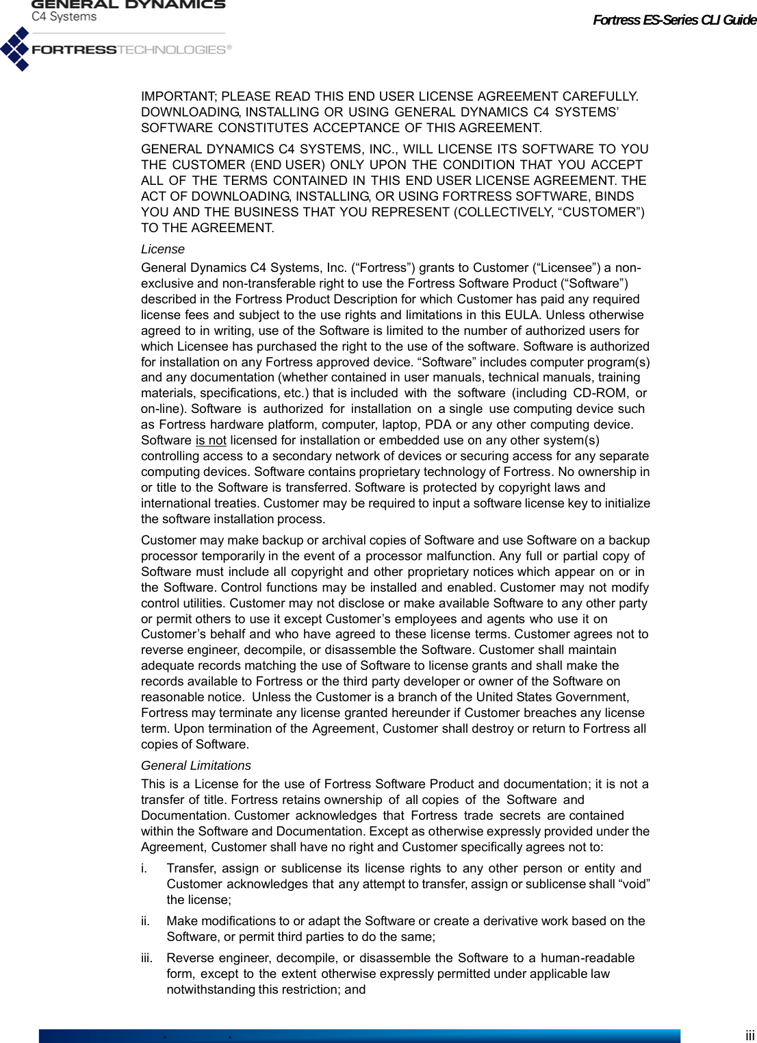
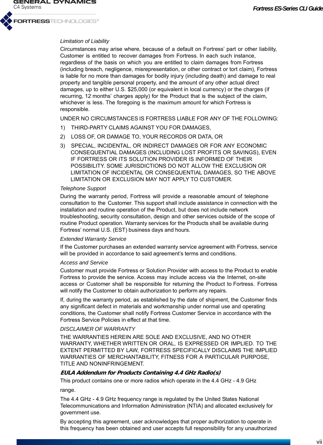
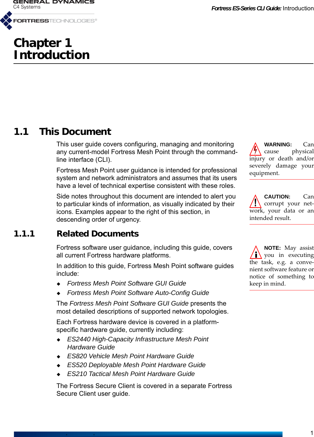
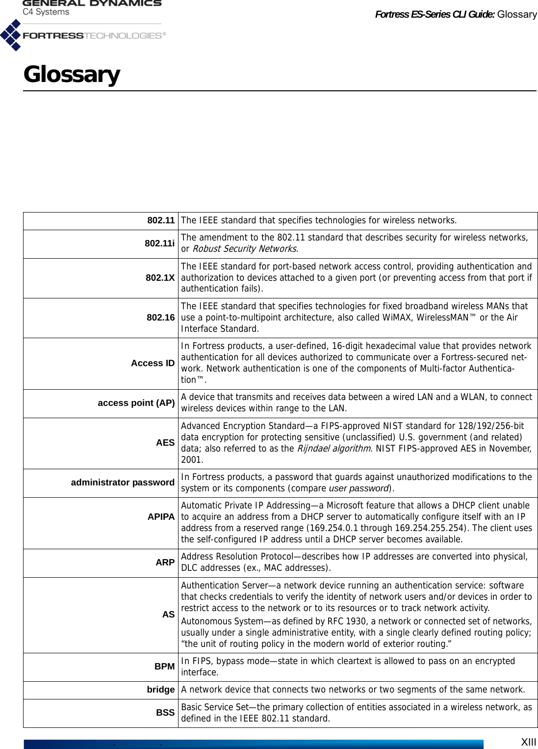
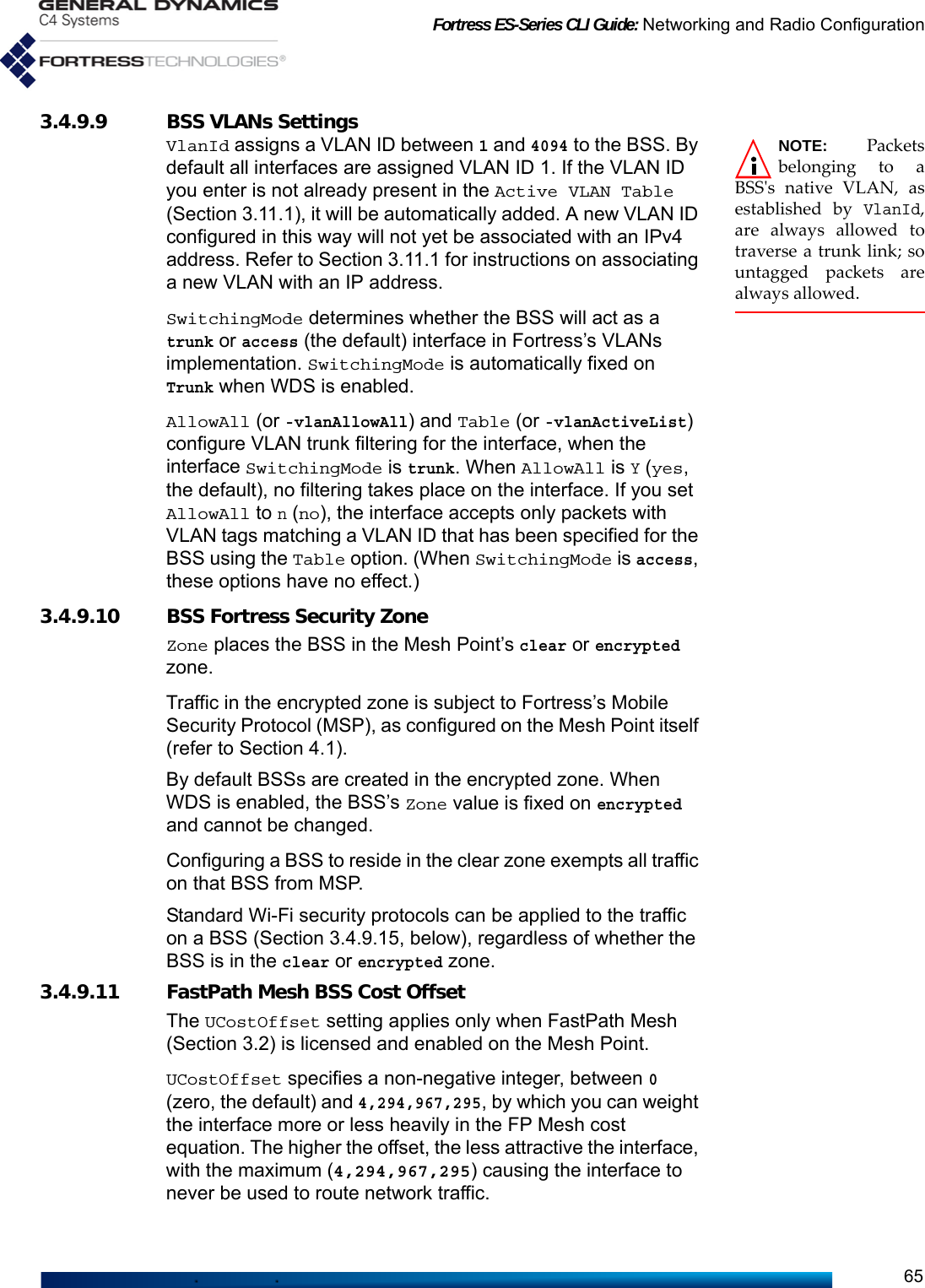
![Fortress ES-Series CLI Guide: Introduction4DeviceIP: 192.168.4.9Gui: OnSsh: OnSnmp(V3): OffFirmware version: 1.14.52Time till reboot: not set Figure 1.1 ES-Series Product Model Number ExplicationCAUTION: Use of4.4 GHz radios inthe U.S. without govern-ment approval is strictlyforbidden. The Platform identifier for Fortress's first generation ES-series Mesh Points is three digits, as shown in Figure 1.1. The number “2” prefixed to the ES2440’s platform number identifies the High-Capacity Infrastructure Mesh Point as a next generation ES-series Fortress platform. The second-to-last digit in the platform number represents the maximum number of radios the platform chassis can accommodate.The number of non-zero digits after the hyphen corresponds to the actual number of radios installed in the Mesh Point. The value of each digit indicates the frequency band(s) that radio supports, as shown in Table 1.2.Only the ES2440 supports an option for Multiple-Input Multiple-Output ()-capable 4.4 GHz radios, indicated by the “m” appended to these two model numbers: ES2440-34m, ES2440-3444m (All standard equipment ES2440 radios [802.11a/g/n and 802.11a/n] support).A zero following the hyphen in an ES-series model number indicates a Mesh Point with no radios installed.1.3.1.2 Fortress Mesh Point ManagementFortress Mesh Points can be administered through either of two native software management tools. They support SNMP (Simple Network Management Protocol) transactions, and each model chassis provides a small subset of basic user controls and visual indicators.Table 1.2 Radio Installed and Supported FrequenciesNumber Radio Installed Supported Frequencies3 802.11a/g or 802.11a/g/n 2.4 GHz or 5 GHz4 802.11 4.4 GHz 4.4 GHz5 802.11a or 802.11a/n 5 GHz](https://usermanual.wiki/General-Dynamics-Mission-Systems/ES520P/User-Guide-2811717-Page-19.png)

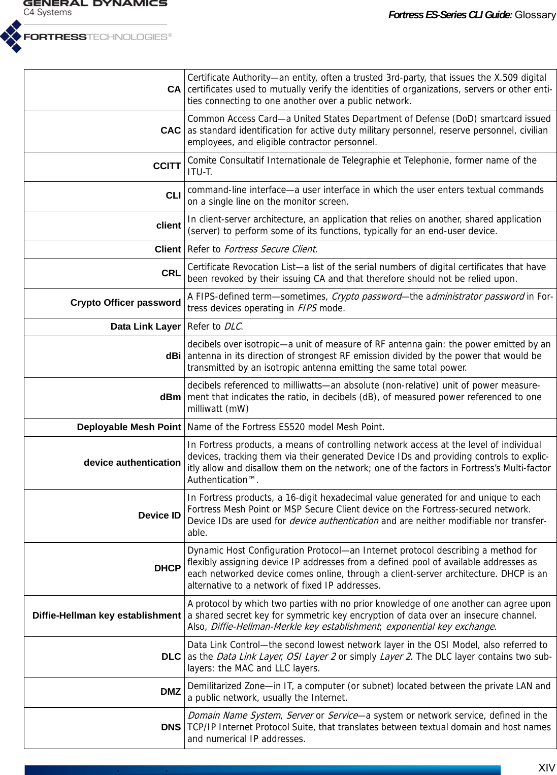
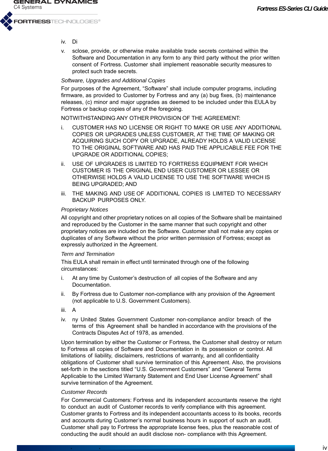
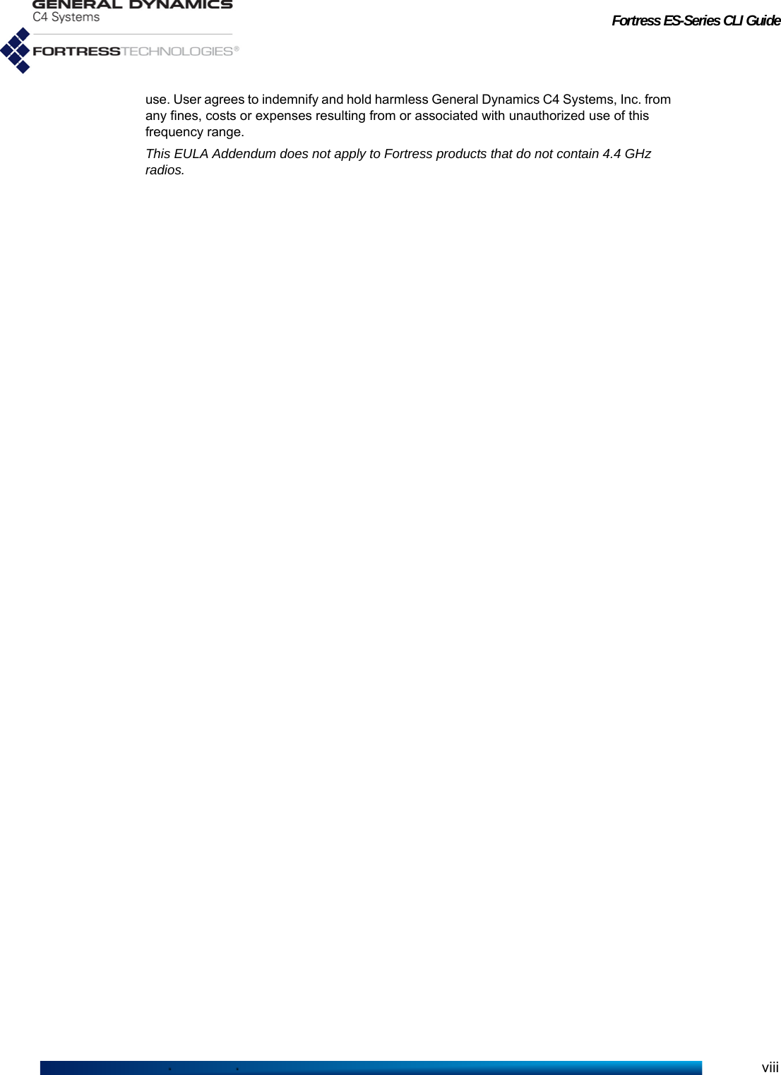
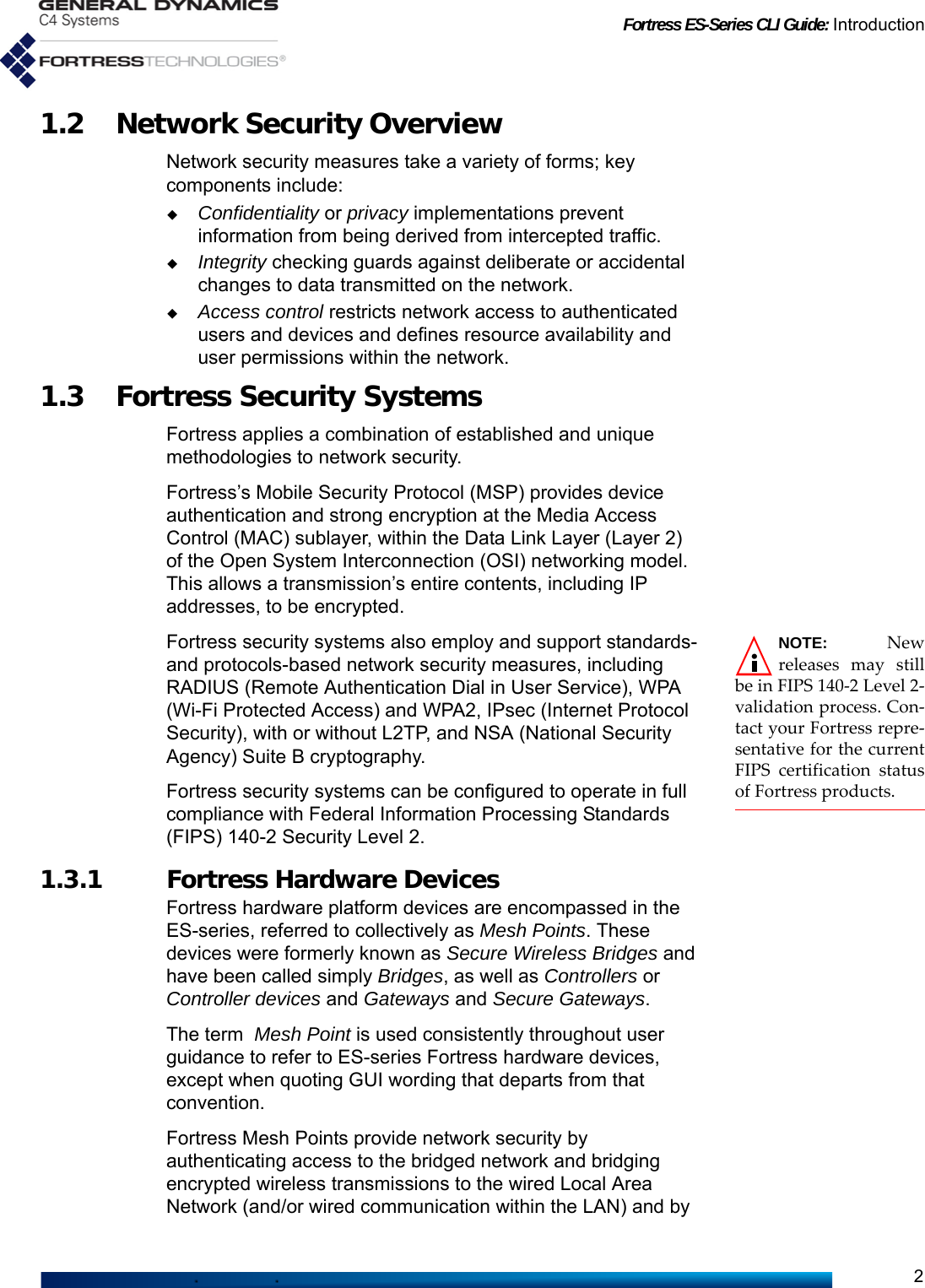
![Fortress ES-Series CLI Guide: Mesh Point CLI and Administrative Access7Chapter 2Mesh Point CLI and Administrative Access2.1 Mesh Point CLINOTE: FortressMesh Point fea-tures and functions aredescribed in greaterdetail in the SoftwareGUI Guide.The Fortress Mesh Point’s command-line interface provides a complete set of commands for managing the Fortress Mesh Point and the network it secures, through a direct connection to the Mesh Point’s serial console port or remotely, through the Mesh Point’s encrypted or clear zone, using Secure Shell (SSH).Up and down (↑↓) arrow keys scroll through the command history for a given CLI session, and the left and right (←→) arrow keys navigate the current command line. If your terminal keyboard is not equipped with arrow keys, you can use these keyboard equivalents:NOTE: These keysmay function dif-ferently based on set-tings in your terminalemulation software. The Tab key auto-completes partial commands sufficient to uniquely identify the command.Mesh Point CLI commands return [OK] when settings are successfully changed and an [Error] message, including a brief description of the error, when commands fail.The clear command clears the CLI display.Lengthy CLI output can be scrolled one screen a time, in most cases, by appending more to the command and then paging through the output with Enter↵ or the space bar. Strike Ctrl-c to truncate scrolled output or to quit an interactive command without making changes.arrow/numeric keypad keyboard equivalentup arrow (↑) Ctrl-udown arrow (↓)Ctrl-dleft arrow (←)Ctrl-lright arrow (→)Ctrl-rHome Ctrl-aEnd Ctrl-e](https://usermanual.wiki/General-Dynamics-Mission-Systems/ES520P/User-Guide-2811717-Page-22.png)
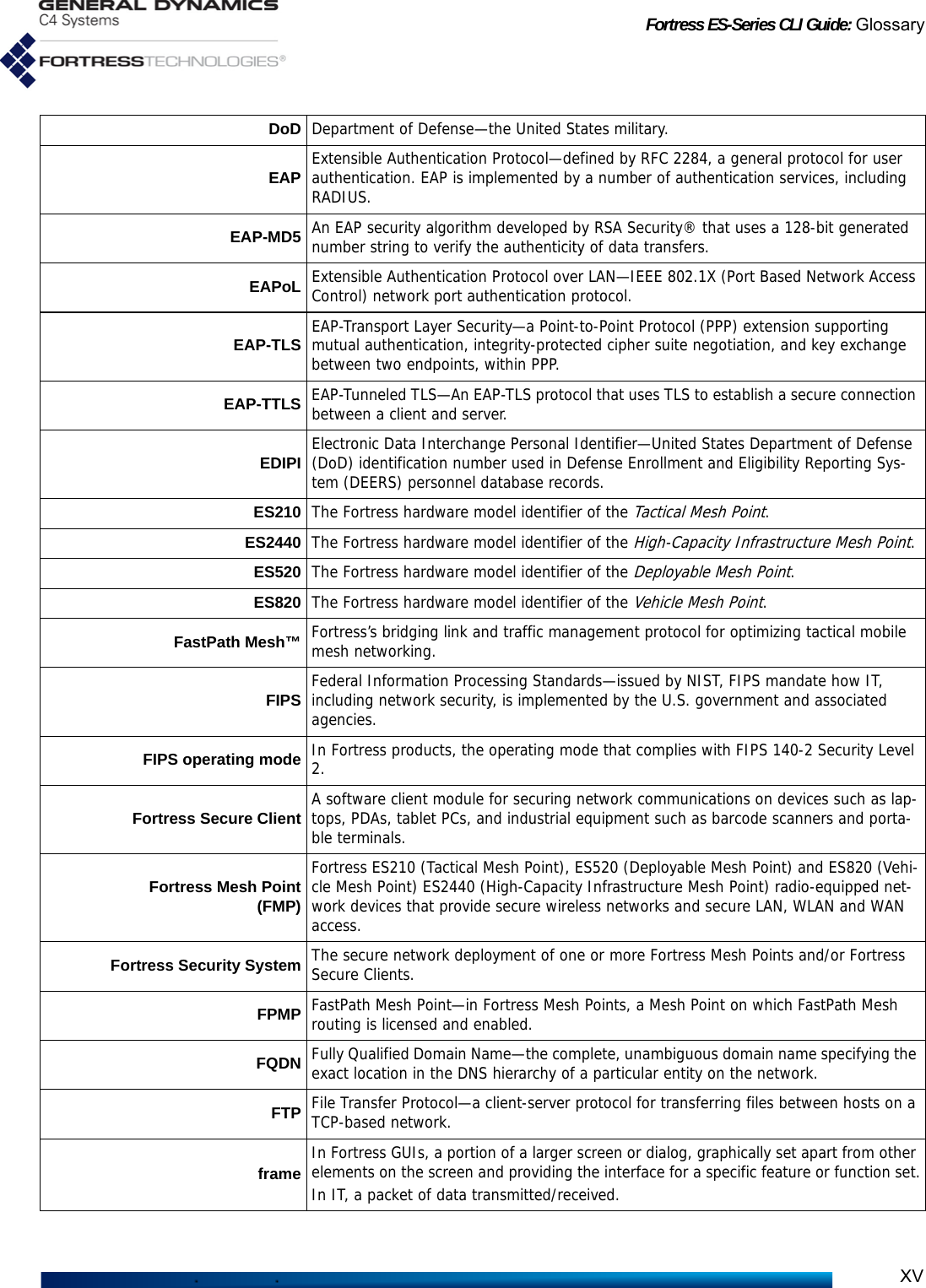
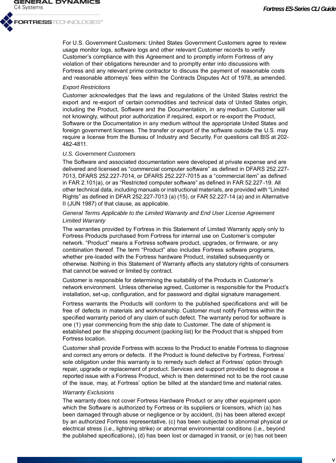
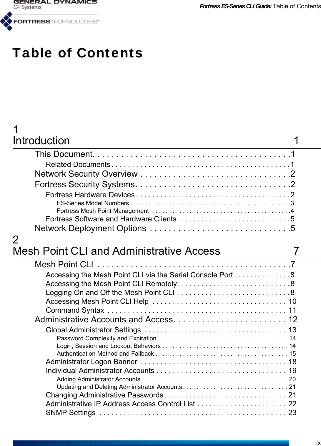
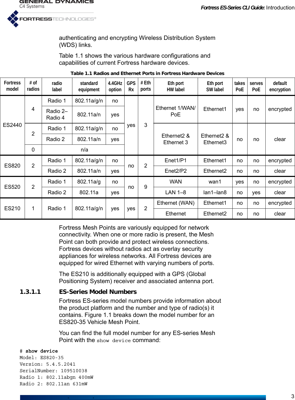
![Fortress ES-Series CLI Guide: Mesh Point CLI and Administrative Access9If the administrative account you are logging on to requires the password to be changed, you must do so before you can proceed and then log on again with the new password to gain access through the account.As shown, if the first password entry fails the complexity check, the Mesh Point CLI automatically displays the password requirements in effect on the Mesh Point. Administrative password rules are global and configurable (refer to Section 2.2.1).Login: logviewerPassword:<password>Please enter a new password:<newpassword>Please confirm the new password:<newpassword>The new password does not meet complexity requirementsHistory Depth: 0Minimum Capital Letters: 0Minimum Lower Case Letters: 0Minimum Numbers: 1Minimum Punctuation Marks: 0Minimum Differences: 0Minimum Length: 12Expires: NExpiration: 60Expiration warning: 10Force reset to conforming password: YDisplay previous login: disableInactivity Timeout: 10Use Dictionary: disableAllow Consecutive Characters: enableMaxAttempts: 3LockoutPermanent: NLockoutDuration: 0AccountAuthMethod: localAccount: enablePlease enter a new password:<newpassword2>Please confirm the new password:<newpassword2>ES-00148c081080-FIPS>If the account you try to log on to has an active administrative session in progress, the Mesh Point queries your intent:ES-00148c081080 Login: adminPassword:Warning! This account already has an active session. Would you like to end the other session or cancel this login? [ endsession | cancel ] endsessionThe command prompt reflects whether the role of the account you are logged on to grants view-only privileges (maintenance and logviewer) or full administrator-level privileges. Accounts with view-only roles use the angle-bracket prompt: >. The hash prompt: # indicates that you are logged on to an administrator-level account.](https://usermanual.wiki/General-Dynamics-Mission-Systems/ES520P/User-Guide-2811717-Page-24.png)
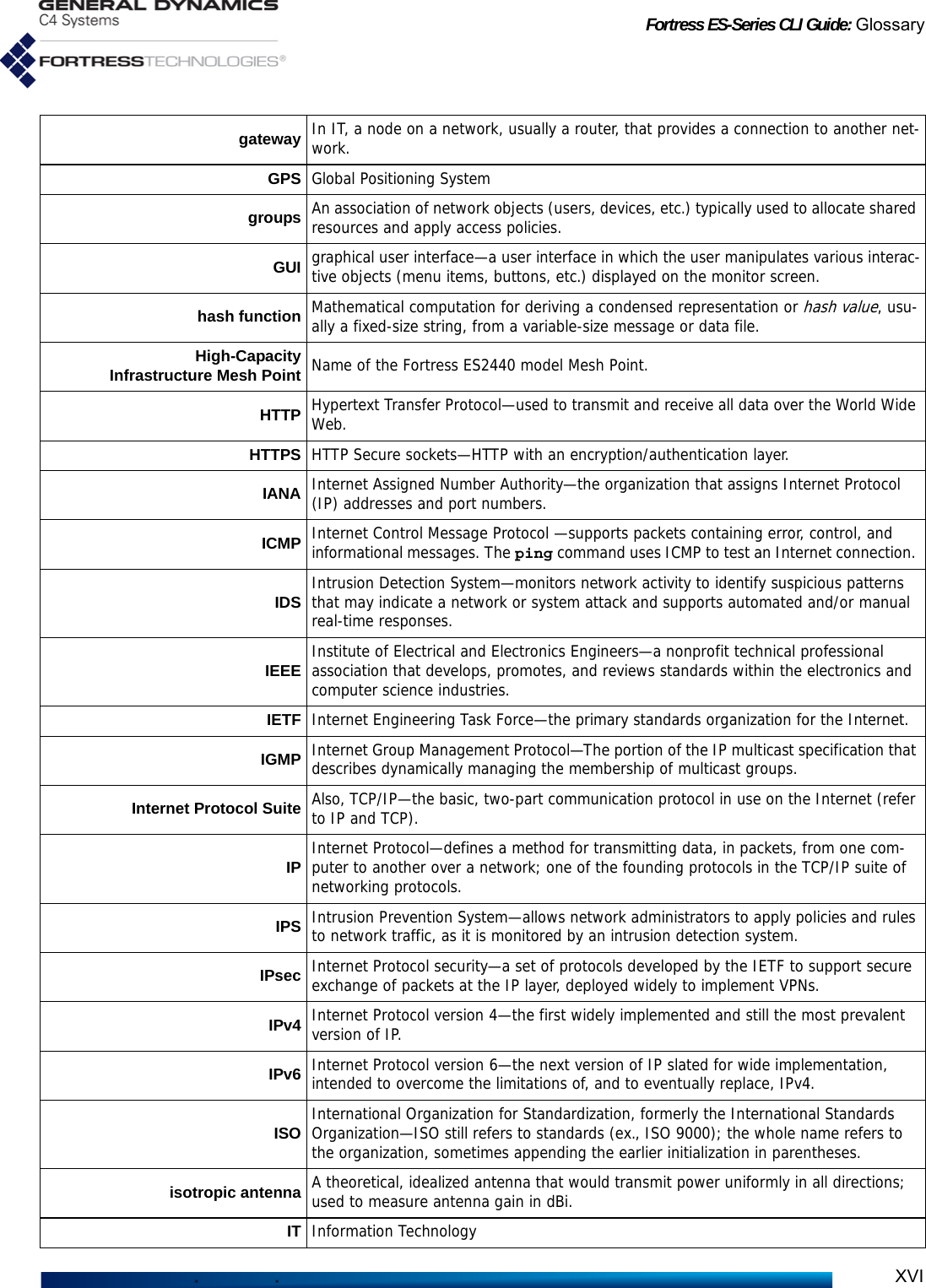
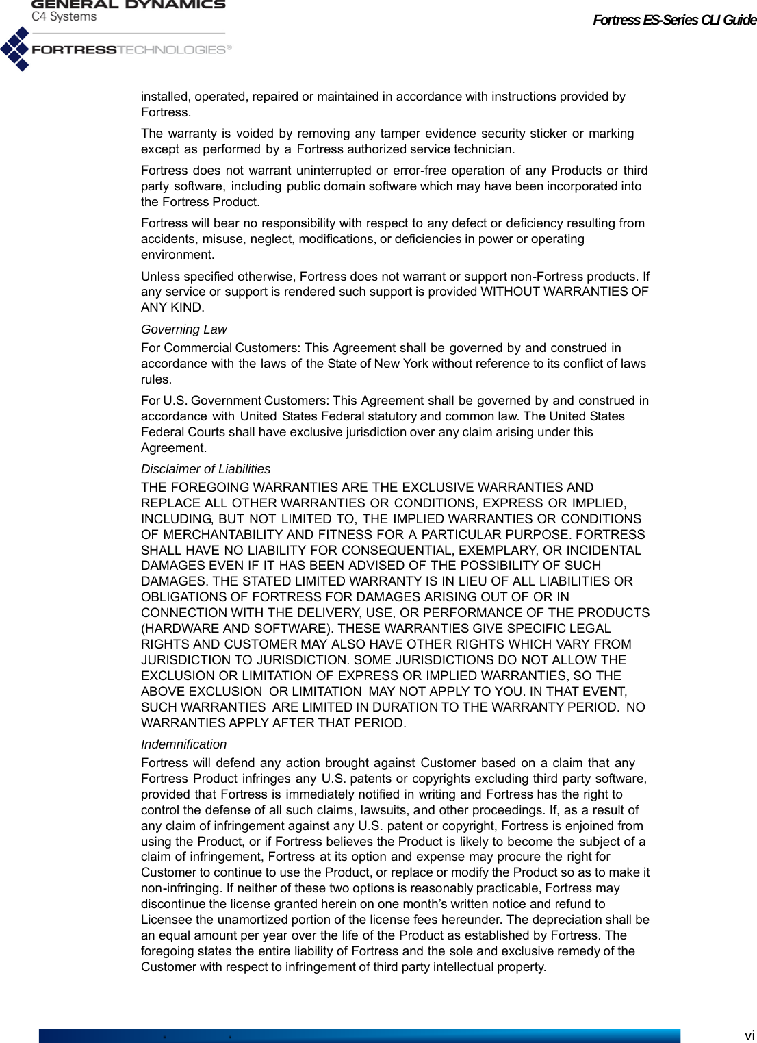
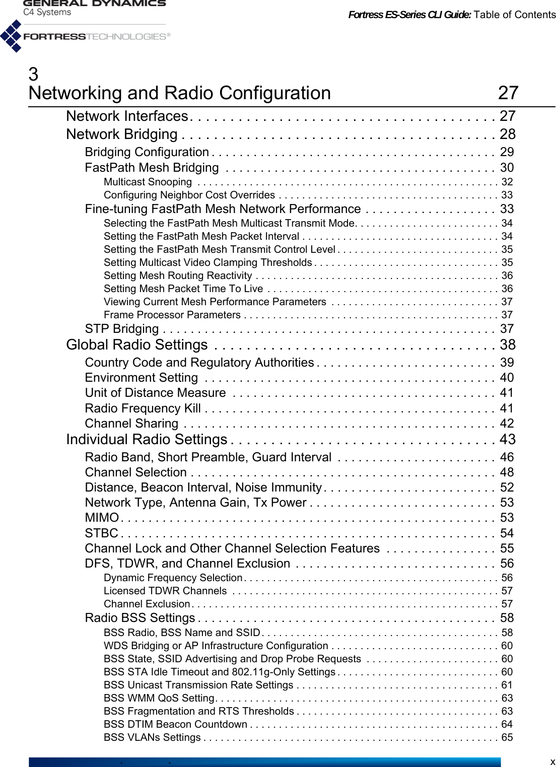
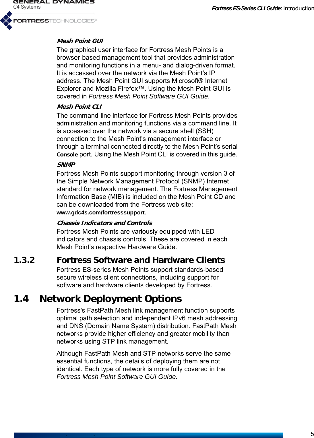
![Fortress ES-Series CLI Guide: Mesh Point CLI and Administrative Access10To log off the Mesh Point CLI, use exit or its synonyms:> exit> quit> qThe Mesh Point CLI will time out and exit after a specified period of inactivity (10 minutes, by default), and you must log back in to regain access. This behavior is configurable (refer to Section 2.2.1).2.1.4 Accessing Mesh Point CLI HelpUse the help command (or its synonym, ?) without arguments to obtain a list of valid commands.You can obtain a usage example—and list the command’s valid options with their valid arguments—by entering a basic command without options:> showDescription: Displays system information, configurationUsage: show [args]. Possible args: account Displays account status and security setting ace Displays access control entries admin Displays Admin Users ap Displays Access Points association Displays current associations audit Displays audit configuration auth Displays authentication servers banner Displays Welcome banner blackout Displays blackout mode status blocked Displays list of blocked MAC addresses bootimage Displays boot images bridgelinks Displays current WDS bridge links bridging Displays bridging mode information bss Displays Basic Service Sets cachedauth Displays whether re-authentication is enforced certificate Displays X.509 certificates certificate-revocation Displays Certificate Revocation Configuration--More-- Help output is displayed one page at a time: --More-- signals that you can scroll additional help output, one screen at a time, by striking any key. You can exit the --More-- scrolling function with Ctrl-C.Help output reflects the administrative privileges of the account currently logged onto by displaying help for only those commands available to the current administrator. So, for instance, if you enter the set command without arguments when logged on to a maintenance-level or logviewer-level account, the Mesh Point CLI returns a command not found message:> set[Error] command not found](https://usermanual.wiki/General-Dynamics-Mission-Systems/ES520P/User-Guide-2811717-Page-25.png)
![Fortress ES-Series CLI Guide: Mesh Point CLI and Administrative Access11Obtain a usage example of command options for interactive commands—and list the option’s valid switches and arguments with a brief explanation of each—by entering help (or its synonym, ?) after the command option: # set network ?Description: Sets network configurationUsage: set network [-enable <y|n>][-h hostname][-ip IP][-nm netmask][-gw defaultGW]-enable y|n: to enable IPv4-h hostname: name (will be shown in prompt)-ip IP: a valid IPv4 address for the interface-nm netmask: mask of network prefix (e.g., 255.255.255.0)-gw defaultGW: IPv4 address of default gateway. To remove: -gw 0.0.0.0For help with non-interactive command options, you can enter the command-option combination without arguments:# set accessidDescription: Sets Access ID from a HEX stringUsage: set accessid default|random|<HexString> [-confirm default|random|<HexString>] default Sets to factory default value random Sets to an auto-generated pseudorandom value <HexString> Sets to a Hex string 16|32 chars (exclude optional colons). Ex: 00:11:22:AA:BB:CC:DD:EE2.1.5 Command SyntaxIn this document, command-line text supplied by the Mesh Point CLI is set in plain (non-bold, non-italic) type. All user input is indicated by bold typeface. The template for the Mesh Point CLI command syntax is shown below:# command option <parameter> -switch req_arg1|req_arg2|req_arg3 -switch opt_arg1|opt_arg2in which you can also note the terminology and punctuation used here to describe command strings and parse input elements:Command refers to the basic operation to be performed (ex., set, show, etc.).Option refers to the configuration element upon which the command will operate (ex., clock, ap, clients, etc.)Parameter refers to a user-supplied variable, (ex., <name>, <IPaddr> (IP address), etc.). Arguments (_arg, above) are additional command inputs. Some arguments are required by the command (req_arg). Others are optional (opt_arg). Multiple arguments must be separated by commas and entered without spaces.Switch refers to the identifier, preceded by a dash (hyphen), for the argument to follow (ex., -ip, -n, etc.) Switches allow permissible arguments to be entered in any combination and order.](https://usermanual.wiki/General-Dynamics-Mission-Systems/ES520P/User-Guide-2811717-Page-26.png)
![Fortress ES-Series CLI Guide: Mesh Point CLI and Administrative Access14Failures:---------Password changes rejected for history: 0Password changes rejected for complexity: 0Password changes rejected for uniqueness: 02.2.1.1 Password Complexity and ExpirationHistory Depth specifies how many new passwords must be created for administrator accounts before previously used passwords can be reused. Minimums can be set for the numbers of upper- and lowercase letters, numerals, symbols, and differences from the last password that passwords must contain, along with the minimum total number of characters (Minimum Length) required.By default, password expiration is disabled for locally authenticated administrative accounts (Expires: N). When it is enabled (Expires: Y), you can set the password expiration period and configure the Mesh Point to warn administrators (at logon) for a specified number of days in advance of expiration. The password expiration period (Expiration) can be set from 1 to 365 days (the default is 60). The Expiration warning can be set from 0 (zero), which disables the warning, to 365 days (the default is 10). In addition, you can direct the Mesh Point to expire non-conforming passwords as soon as requirements change (Force reset to conforming password: Y, the default) or allow them to persist until the next scheduled expiration (or indefinitely, when scheduled expiration [Expires] is disabled).Unbroken alphabetic strings within administrator passwords can also be checked against a list of known words and checked for numerically or alphabetically consecutive characters (in ascending or descending order) and repeated consecutive characters. Use Dictionary and Allow Consecutive Characters are disabled by default.2.2.1.2 Login, Session and Lockout BehaviorsYou can configure the Mesh Point to display details of the last log on to the account to locally authenticating administrators when they log on: NOTE: The idletimeout setting forlocal administratoraccounts is indepen-dent of timeout settingsfor network users andconnecting devices con-figured on the internalauthentication server(Section 4.5.2).Login: adminPassword:Last logged in at Wed Jul 16 00:54:03 2008Last logged in from address 10.1.1.1Last logged in from console interfaceThe Display previous login feature is disabled by default.By default, administrative accounts time out after ten minutes of inactivity. You can turn the feature off by specifying 0 (zero) for UI Session Idle Timeout, or reconfigure the setting, in minutes, up to 60. UI Failed Attempt Time Holddown](https://usermanual.wiki/General-Dynamics-Mission-Systems/ES520P/User-Guide-2811717-Page-29.png)
![Fortress ES-Series CLI Guide: Mesh Point CLI and Administrative Access16To use the internal Fortress RADIUS Server to authenticate administrators:You must execute the commands below in the order given.1Enable the internal authentication server to provide local authentication:# set localauthEnableLocalAuth[N] (Y|N to enable|disable local authentication server): yPort[1812] (Port number to communicate):SharedKey (Authentication key): authkeyPriority (Local server priority [0..999]):RetryInterval (Time in seconds for retrying [1..600]):EnableDevAuth[N] (Y|N to enable|disable Device authentication):EnableUserAuth[N] (Y|N to enable|disable User Authentication):DefaultDeviceState[pending] (pending|allow|deny):DefaultMaxRetries[3] (Maximum attempts at reaching server before failover 1-30, default is 3):DefaultIdleTimeout[30] (User idle timeout in minutes 1-720, default is 30):DefaultSessionTimeout (Authentication timeout in minutes, 1-200, default is 30):EnableAdminAuth[N] (Y|N to enable|disable administrator authentication): yEnable8021xAuth[N] (Y|N to enable|disable 802.1x authentication):EnableEAP-MD5 (Y|N to enable|disable support for EAP-MD5 protocol):EnableEAP-TLS (Y|N to enable|disable support for EAP-TLS protocol):EnableCRLCheck[N] (Y|N to enable|disable CRL check):EnableOcsp[N] (Y|N to enable|disable OCSP):OcspUrl[""] (URL of OCSP responder):EnableOcspNonce[Y] (Y|N to enable|disable OCSP nonce):CaCertUrl[""] (URL of CA certificate or chain):LdapSB[""] (Search base for CA certificate or chain (LDAP only)):TLSCipherSuite (all|legacy|suite-b to set supported cipher suite for EAP-TLS):For help with other set localauth command options, refer to Section 4.5.2.2Verify that authentication failback is at the default setting of enable, and if it is disabled, enable it:# set account -authMethod radius -accountAuthFailback enableFor help with other set account command options, refer to the rest of this section.3Add an account for each administrator you want to be able to authenticate through the internal authentication server:# add userauth -name <admin> -passwd <userpw> -passwordConfirm <userpw>-adminauth administrator|maintenance|logviewerThe password must conform to the password requirements currently in effect. -name must match that of the administrative account for which you are configuring the internal RADIUS account. -adminauth must correctly identify that account’s administrative role.For help with other add userauth command options, refer to Section 4.5.3.](https://usermanual.wiki/General-Dynamics-Mission-Systems/ES520P/User-Guide-2811717-Page-31.png)
![Fortress ES-Series CLI Guide: Mesh Point CLI and Administrative Access17To use a remote Fortress RADIUS Serverto authenticate administrators:To use a RADIUS server running on another Mesh Point on the network to authenticate administrators for the current Mesh Point, you must configure an entry for the remote server on the current Mesh Point (with the add auth command). Only administrators with accounts flagged with an -adminauth option on the remote Mesh Point’s internal RADIUS server will be able to authenticate through this service.To use a third-party RADIUS Serverto authenticate administrators:To use a third-party RADIUS server for administrator authentication, it must be configured to use Fortress’s Vendor-Specific Attributes for Fortress-Administrative-Role and Fortress-Password-Expired, provided in the dictionary.fortress configuration file included on the Mesh Point software CD and available for download at www.gdc4s.com. Consult your RADIUS server documentation for information on configuring the service. An entry for the remote server must also be configured on the current Mesh Point (with add auth).Configure all global administrative logon, password and authentication settings for the Mesh Point with the set account command, as follows:# set accountHistory Depth[0] (0-10, default is 0, maximum number of account changes to track):Minimum Capital Letters[0] (0-5, minimum number of capitals in a password):Minimum Lower Case Letters[0] (0-5, minimum number of lower case letters in a password):Minimum Numbers[0] (0-5, minimum number of digits in a password):Minimum Punctuation Marks[0] (0-5, minimum number of punctuation marks in a password):Minimum Differences[0] (0-5, minimum number of character differences in a new password):Minimum Length[15] (8-32, minimum length of a new password):Expires[N] (Y|N, passwords expire after specified duration):Expiration[60] (1-365, number of days before passwords expire):Expiration warning[10] (0-365, number of days before warning that a new password is needed):Force reset to conforming password[Y] (Y|N, force non conforming passwords to expire):Display previous login[disable] (enable|disable, display information on the last session for this user):UI Session Idle Timeout[0] ([0|60] default is 10, UI Session Idle Timeout in minutes):UI Failed Attempt Time Holddown[5] ([0|60] default is 5, time to wait in seconds before a login will be allowed):Use Dictionary[disable] (enable|disable, use the password dictionary):Allow Consecutive Characters[enable] (enable|disable, allow consecutive characters in a new password):MaxAttempts[3] (1-9, maximum number of failed attempts):LockoutPermanent[N] (Y|N, lock this account permanently):LockoutDuration[0] (0-60, lockout time in minutes if not locked permanently):AccountAuthMethod[local] (local|radius, authentication method to use):AccountAuthFailback[enable] (enable|disable, enables or disables authentication failback):](https://usermanual.wiki/General-Dynamics-Mission-Systems/ES520P/User-Guide-2811717-Page-32.png)
![Fortress ES-Series CLI Guide: Mesh Point CLI and Administrative Access18NOTE: Except for -uiInactivityTimeout changes, whichtake effect immediately,changes to globaladministrator settingsare applied at the nextadministrator logon.The Mesh Point CLI displays the configurable fields for set account one at a time. Enter a new value for the field—or leave the field blank and the setting unchanged—and strike Enter↵, to display the next field.Alternatively, you can execute set account non-interactively with valid switches and arguments in any order and combination:# set account -historyDepth 0-10 -minCapitalLetters 0-5 -minLowerCaseLetters 0-5 -minNumbers 0-5 -minPunctuation 0-5 -minDifference 0-5 -minPasswordLength 8-32 -passwordExpires Y|N -passwordExpiration 1-365 -passwordExpirationWarning 0-365 -forceNonConfExpire Y|N -showLastLogin enable|disable -uiInactivityTimeout 0|1-60 -failedAttemptTimeout 0|1-60 -usedictionary enable|disable -allowconsecutivecharacters enable|disable -maxtry 1-9 -lockoutperm Y|N -lockouttime 0-60 -authMethod local|radius -accountAuthFailback enable|disableNOTE: The pass-word complexityrequirements estab-lished with setaccount apply equallyto administrative andlocal user account pass-words (Section 4.5.3).The Mesh Point CLI returns [OK] when settings are successfully changed.You must be logged on to an administrator-level account to change administrative settings (refer to Section 2.2).2.2.2 Administrator Logon Banner You can configure a logon banner of up to 2000 characters for display when administrators log on to the Mesh Point.View the currently configured WelcomeMessage with show banner:> show bannerIf no logon banner is configured, show banner returns no text. No welcome message is configured by default. Enter a single-line message for display on administrator logon screens with set banner. # set banner -welcome <“banner string”> You can configure a longer banner that spans multiple lines using the command set banner -multi. # set banner -multiEnter multiline text (maximum 2000 chars) and press Ctrl-C to exitWhen a banner is configured, administrators must accept its terms in order to log on.You must be logged on to an administrator-level account to change configuration settings (refer to Section 2.2).](https://usermanual.wiki/General-Dynamics-Mission-Systems/ES520P/User-Guide-2811717-Page-33.png)
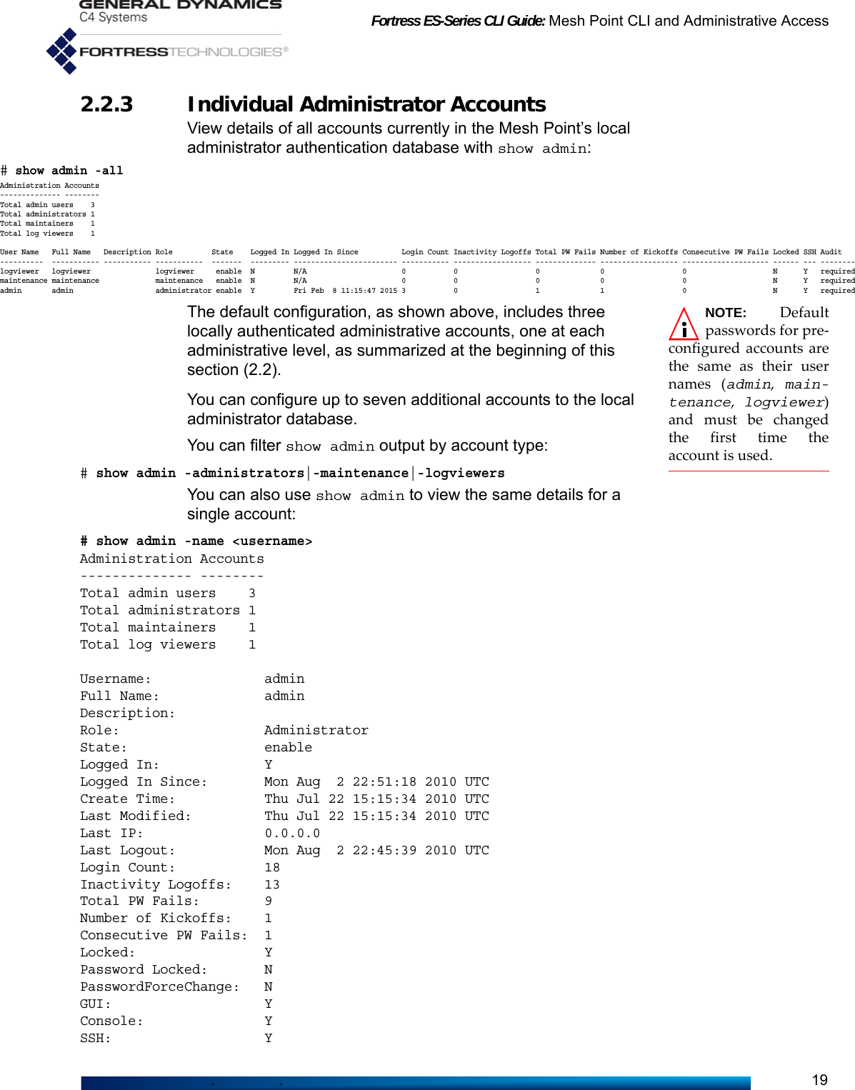
![Fortress ES-Series CLI Guide: Mesh Point CLI and Administrative Access20Audit: required2.2.3.1 Adding Administrator AccountsAdd new accounts to the local administrator database with add admin:# add adminUsername (User name): <adminName>State[enable] ([enable|disable] User state): enable|disableFull Name[""] (Account full name): "<full name>"Description[""] (Account description): "<description of account>"Role[Maintenance] ([logviewer|maintenance|administrator]): administrator|maintenance|logviewerPassword Locked[N] ([y|n] Prevent user from changing password):NOTE: You canexit the interac-tive add admin com-mand without makingchanges with Ctrl-C.PasswordForceChange[N] ([y|n] force user to change password):Password (Password for this user): <adminPassword>Password Confirm (Password for this user): <adminPassword>GUI[enable] ([y|n] Allow user GUI access):Console[enable] ([y|n] Allow user console access):SSH[enable] ([y|n] Allow user CLI access):Audit[required] ([required| prohibited | automatic ] Audit setting):[OK]NOTE: Administra-tor Usernames arecase-sensitive and caninclude spaces and anyof the symbols in theset:~!@#$%^&*()_-+={}[]|\:;<>,.?/ (excludes doubleand single quotationmarks).You must create a unique Username of 1 to 32 characters for the account and configure the State, Role and Password. A disabled account will persist in the database, but cannot be used to log on to the Mesh Point. Account roles are described at the beginning of this section (Section 2.2). Password requirements for local administrative accounts are global and configurable (refer to Section 2.2.1).The Full Name and Description fields are optional, and the double quotation marks are required only when fields contain spaces or special characters (as enumerated in the NOTE to the right).You can enter new values for the remaining fields—or leave a field blank and the setting unchanged by striking Enter↵, to display the next field. These determine whether the account password is locked and cannot be changed (Password Locked: Y) or must be changed the first time the account is used (PasswordForceChange: Y). Both options are disabled by default, and if you enable PasswordForceChange, it will reset to N (disabled) after the account holder has successfully changed the password during initial logon.By default, administrative accounts are created with permission to access the management interface by any means: network access to the Mesh Point GUI (gui) or CLI (cli) and terminal access to the Mesh Point CLI through the front-panel Console port (console). You can selectively disable access to any interface for a given account.Finally, remote audit logging of activity on the account can be configured. By default, audit logging is required, which includes all activity on the account in the audit log. A setting of prohibited excludes all account activity from the audit log. An](https://usermanual.wiki/General-Dynamics-Mission-Systems/ES520P/User-Guide-2811717-Page-35.png)
![Fortress ES-Series CLI Guide: Mesh Point CLI and Administrative Access21Audit setting of automatic causes the account to conform to the global audit logging settings (refer to Section 4.7).Alternatively, you can execute add admin non-interactively with valid switches and arguments in any order and combination:# add admin -name <username> -state enable|disable -fullname <“Full Username”>-desc <“description of account”> -role administrator|maintenance|logviewer -passwordlock Y|N -passwordforcechange Y|N -password <password> -passwordconfirm <password> -gui enable|disable -console enable|disable -ssh enable|disable -audit required|prohibited|automaticThe Mesh Point CLI returns [OK] when settings are successfully changed.NOTE: Changes tothe account youare currently loggedonto will take effect thenext time you log on.2.2.3.2 Updating and Deleting Administrator AccountsOnce an administrative account has been established, you cannot change the user name associated with it. Use the -name switch with the update command to reconfigure the account of the administrator you specify. The same switches and arguments used with add admin (above) can be used to edit other account settings:# update admin -name <username> -state enable|disable -fullname <“Full Username”>-desc <“description of account”> -role administrator|maintenance|logviewer -passwordlock Y|N -passwordforcechange Y|N -oldpassword <oldpassword> -password <password> -passwordconfirm <password> -gui enable|disable -console enable|disable -ssh enable|disable -audit required|prohibited|automatic -endsessionThe -endsession switch, which takes no arguments, can be used only with update admin. It forces a current session of the named administrative account to terminate immediately.NOTE: If a manu-ally added accountis the only account cur-rently configured with arole of administra-tor, del admin -allwill not delete it.You can delete a specified administrator account (except for the three preconfigured accounts and (if different) the only remaining account with a role of administrator). You can also delete all manually added administrative accounts with the del command:# del admin -name <username>|-allYou must be logged on to an administrator-level account to create, update and delete administrative accounts (refer to Section 2.2).2.2.4 Changing Administrative Passwords You can change any password from an administrator-level account, including your own:# update admin -name <Username> -oldpassword <oldPassword> -password <newPassword> -passwordconfirm <newPassword>Provided the password is not locked (refer to Section 2.2.3), administrators with maintenance- or logviewer-level accounts can change their own passwords using the same command options.](https://usermanual.wiki/General-Dynamics-Mission-Systems/ES520P/User-Guide-2811717-Page-36.png)
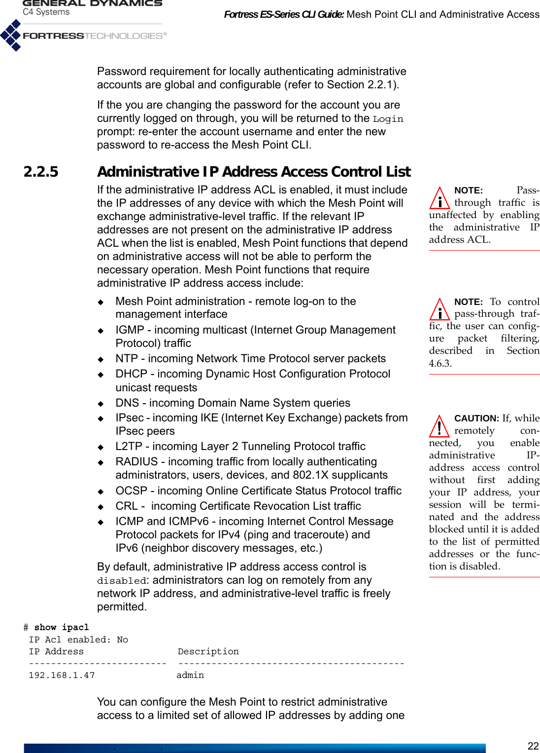
![Fortress ES-Series CLI Guide: Mesh Point CLI and Administrative Access23or more permitted IP addresses (with optional descriptions) to the IP address access control list and enabling the function:# add ipacl -ip <IPaddress> -desc <Description>[OK]# set ipacl -enable y [OK]You can add additional IP addresses to the permitted list at any time.You can delete a specified IP address or all IP addresses on the list:# del ipacl -ip <IPaddress>|allYou must be logged on to an administrator-level account to change configuration settings (refer to Section 2.2).2.2.6 SNMP Settings NOTE: SNMPauthentication isalways directed to thelocal authenticationserver. This is thebehavior even ifRADIUS authenticationis enabled.The Fortress Mesh Point can be configured for monitoring through Simple Network Management Protocol (SNMP) version 3. Fortress Management Information Bases (MIBs) for the Mesh Point are included on the Mesh Point CD-ROM and can be downloaded from www.gdc4s.com/fortresssupport.When SNMP v3 support is enabled, the SNMP v3 user (FSGSnmpAdmin) access to the Mesh Point is authenticated via the SHA-1 message hash algorithm as defined in IETF RFC1 2574, User-based Security Model (USM) for version 3 of the Simple Network Management Protocol (SNMPv3), using the specified authentication passphrase. SNMP v3 privacy is secured via the Advanced Encryption Standard with a 128-bit key (AES-128), using the specified privacy passphrase.SNMP v3 is disabled on the Mesh Point by default.View the current SNMP configuration with show snmp:> show snmp[SNMP Configuration]EnableV3SNMP: YContact: <contact>Description: <description>Location: <location>EnableTrap: YEngineID: <engineID>[SNMP Trap][SNMP Statistics]Total Packets In: 0Total Packets Out: 0----------1. Internet Engineering Task Force Request for Comments](https://usermanual.wiki/General-Dynamics-Mission-Systems/ES520P/User-Guide-2811717-Page-38.png)
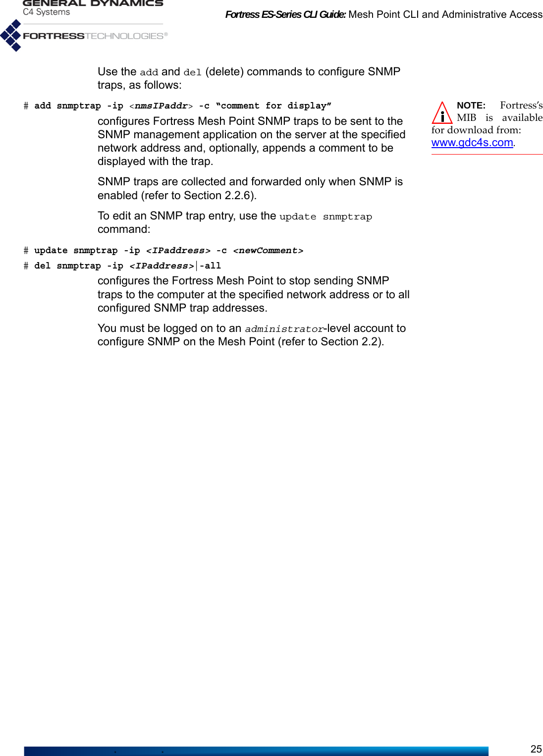
![Fortress ES-Series CLI Guide: Mesh Point CLI and Administrative Access24Audit Status: requiredSNMP is disabled on the Mesh Point by default.To configure SNMP:Configure the Mesh Point’s SNMP settings interactively with set snmp:# set snmpEnableV3SNMP[N] (Y|N to enable|disable Version 3 SNMP): yContact[""] (Name of contact person): <admin@domain.com>Description["Fortress Security Controller"] (System description):Location[""] (Name of location): <locationID>EnableTrap[Y] (Y|N to enable|disable trap):PrivacyPassphrase (Privacy passphrase string): <PrivPassphrase>PrivacyPassphraseConfirm (Confirm privacy passphrase string): <PrivPassphrase>AuthPassphrase (Authentication passphrase string): <AuthPassphrase>AuthPassphraseConfirm (Confirm authentication passphrase string): <AuthPassphrase>ConfiguredEngineID[""] (5 to 32 character SNMP EngineID for this device):NOTE: The SNMPv3 username isFSGSnmpAdmin andcannot be changed.In addition to enabling or disabling SNMP v3, you can enter a contact E-mail address to serve as the SNMP Contact, provide a new Description of the Mesh Point (Fortress Controller, by default) and identify the Location of the Mesh Point. You can optionally enable/disable SNMP traps. If you enable SNMP v3, you must also enter and confirm SNMP v3 authentication and privacy passphrases of 15–32 alphanumeric characters (without spaces).Alternatively, you can use the set snmp command with valid switches and arguments to configure SNMP on the Mesh Point:# set snmp -enable y|n -c <contact> -d <description> -l <location> -trap y|n -authpass <AuthenticationPassphrase> -authpassconfirm <AuthenticationPassphrase>-privpass <PrivacyPassphrase> -privpassconfirm <PrivacyPassphrase> -engineid <IDstring> -defengineidSNMP traps are disabled (n), by default, and no traps will be sent until trap destinations are added to the Mesh Point’s SNMP configuration (below). With -engineid, you can specify a 5–32 character string to serve as an SNMP engine ID to uniquely identify the SNMPv3 agent on the Mesh Point. Use -defengineid by itself to clear a configured SNMP engine ID by restoring the default ID (unique per Mesh Point).To configure SNMP traps When SNMP traps are configured, the SNMP daemon running on the Mesh Point detects certain system events and sends notice of their occurrence to a server running an SNMP management application, the network management system (NMS), or trap destination.](https://usermanual.wiki/General-Dynamics-Mission-Systems/ES520P/User-Guide-2811717-Page-39.png)

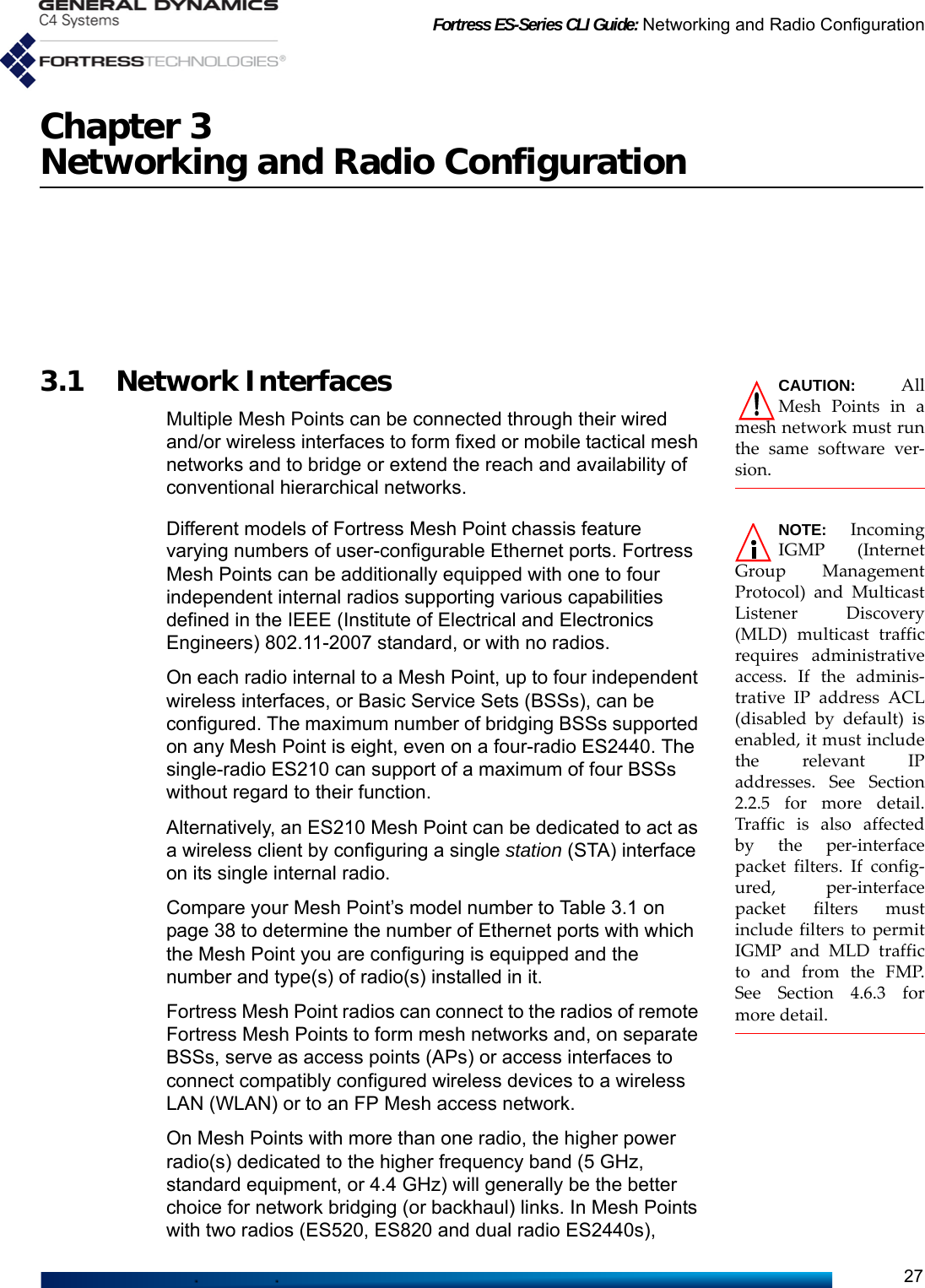
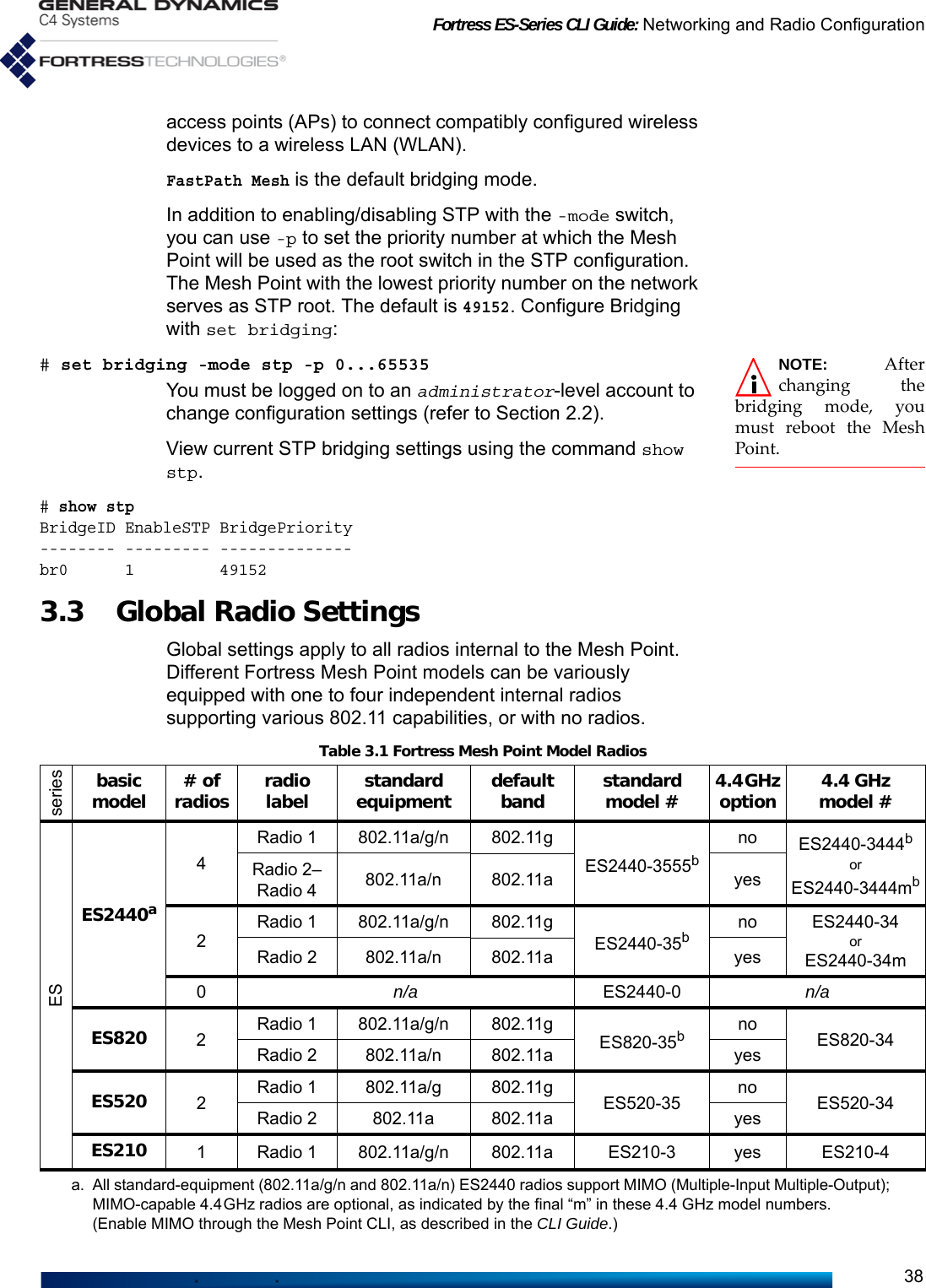
![Fortress ES-Series CLI Guide: Networking and Radio Configuration29On certain model Mesh Points (ES820-35, ES2440-35, ES2440-3555, ES2440-3444 and ES2440-3444m), FastPath Mesh also permits multiple internal radios to be combined into a single virtual FastPath Mesh bridging radio using a common channel (refer to Section 3.3.5 for more detail).Supported FastPath Mesh and STP network topologies are illustrated and described in detail in the Introduction to the Fortress Mesh Point Software GUI Guide.You must be logged on to an administrator-level account to change configuration settings (refer to Section 2.2).3.2.1 Bridging ConfigurationCAUTION: In orderto prevent bridg-ing loops (multiple OSI[open systems intercon-nection] layer 2 paths tothe same device), youmust use -mode stp or-mode mesh on net-worked Mesh Points.The Mesh Point uses FastPath Mesh bridging by default. STP is available if enabled on the Mesh Point. View the current bridging configuration with show bridging. The output varies based on the type of bridging that is enabled. With FastPath Mesh enabled, the show bridging output shows the subnet ID and zone (encrypted or clear), as well as the Mobility Factor, Cost Parameters (described below) and Configured values. > show bridgingmesh: enabled subnetId: 0x8895 zone: encryptedstp: disabledMobility Factor: 10Cost Parameters:'a' Cost Value: 1'b' Cost Value: 1Configured values: mode: mesh subnetId: 0x8895 zone: encryptedWith STP enabled, the show bridging output shows the bridge priority and Mesh Point name, as well as the Mobility Factor and Cost Parameters (described below) and Configured values.> show bridgingmesh: disabledstp: enabled priority: 49152 name: br0Mobility Factor: 10Cost Parameters:'a' Cost Value: 1'b' Cost Value: 1Configured values: mode: stp](https://usermanual.wiki/General-Dynamics-Mission-Systems/ES520P/User-Guide-2811717-Page-44.png)
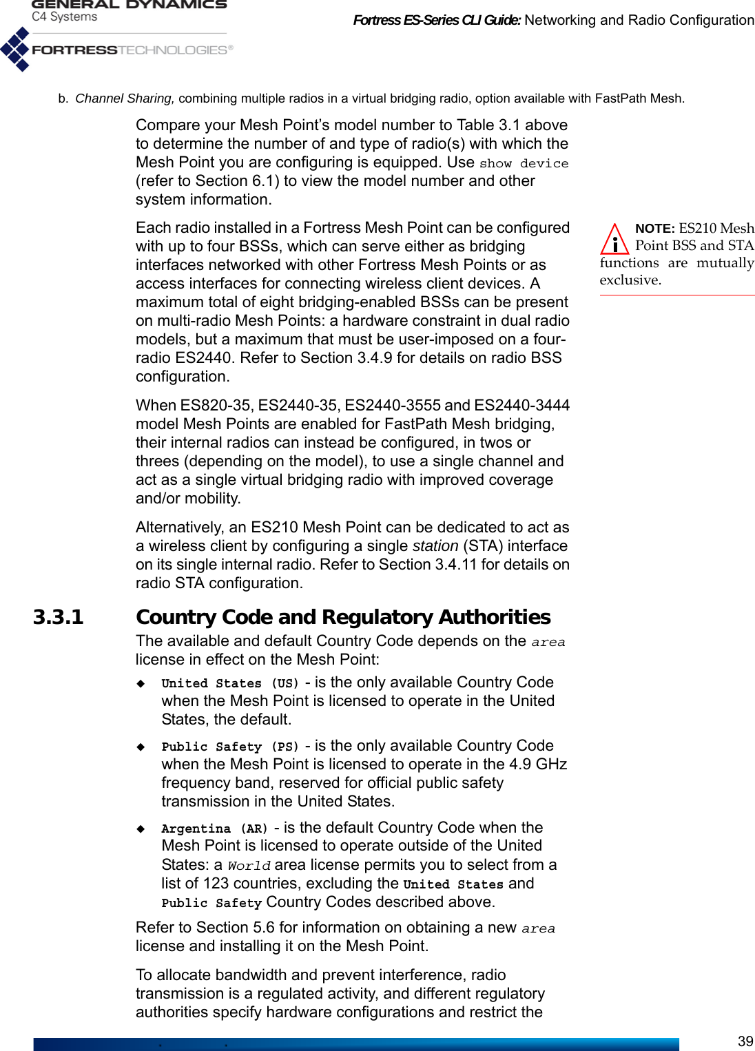
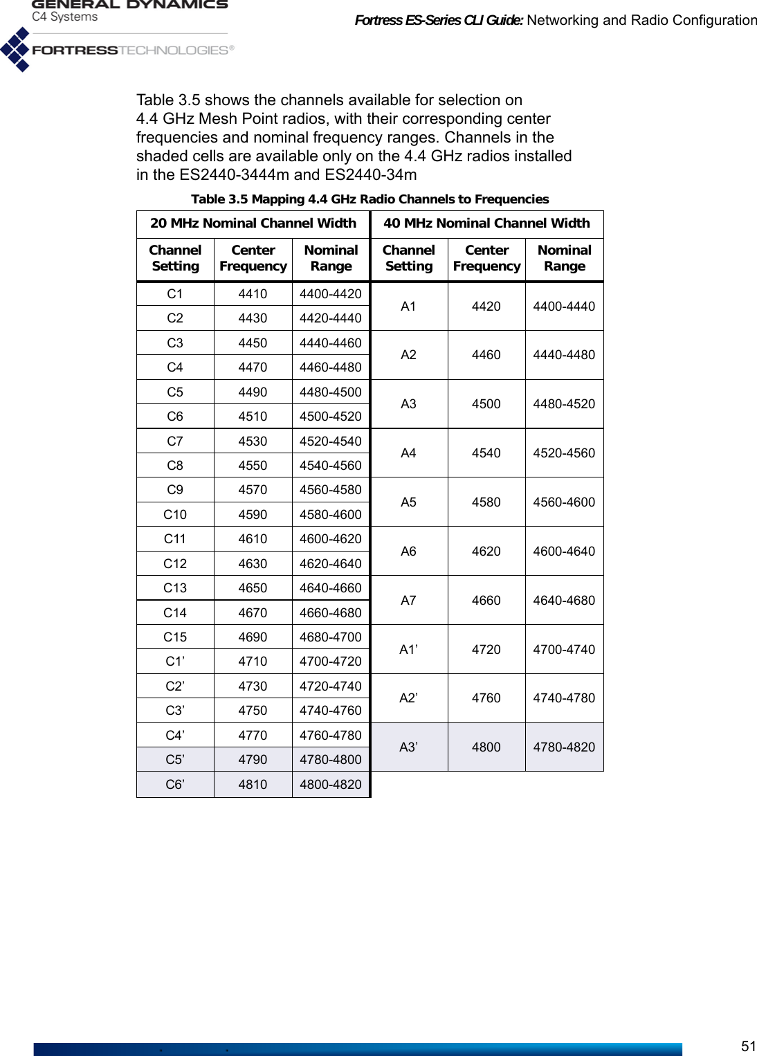
![Fortress ES-Series CLI Guide: Networking and Radio Configuration40strength of signals broadcast on particular frequencies according to different rules.If necessary, the Mesh Point filters options available for individual radio settings (Section 3.4) according to the requirements of the relevant regulatory domain as they apply to the Mesh Point’s internal radios.In order to comply with the requirements of the relevant regulatory domain, the Country code must accurately identify the country in which the Mesh Point will operate or, in the case of the US Public Safety code, the context in which it will be used. The rules of the Federal Communication Commission (FCC) regulatory domain dictate available radio settings in the 5 GHz 802.11a and the 2.4 GHz 802.11g frequency bands in the United States.The 4.4 GHz - 4.9 GHz frequency range is regulated by the United States National Telecommunications and Information Administration (NTIA). Use of 4.4 GHz radios in the U.S. without government approval is strictly forbidden. View the country currently specified with show country:> show country USThe help output for set country provides the country codes for all countries that can be specified.# set countryUsage: set country CountryShortName[US]Possible Countries:US United StatesNOTE: Changingthe Country Coderequires you to rebootthe Mesh Point (see Sec-tion 5.2).Establish the Mesh Point’s country of operation with set country:# set country <CountryCode>The US is specified by default.3.3.2 Environment Setting NOTE: Contactyour Fortress rep-resentative about inter-national and specializedlicensing options.Mesh Points in the U.S. are restricted to outdoor use. The setting is therefore fixed on outdoor on Mesh Points licensed for U.S. operation (the default), and the set environment command cannot be used.You can, however, view the environment setting with show environment:> show environmentoutdoor](https://usermanual.wiki/General-Dynamics-Mission-Systems/ES520P/User-Guide-2811717-Page-55.png)
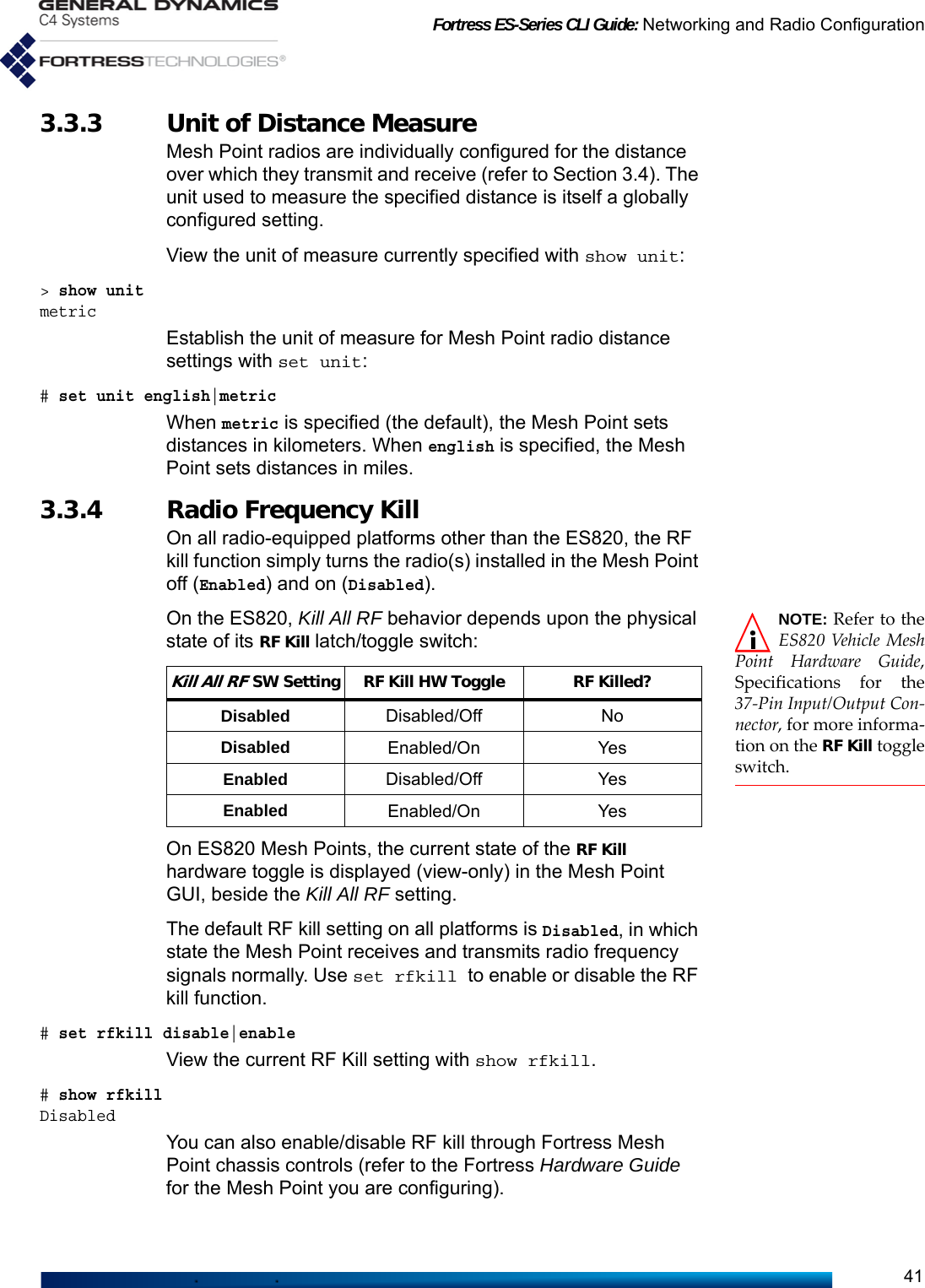
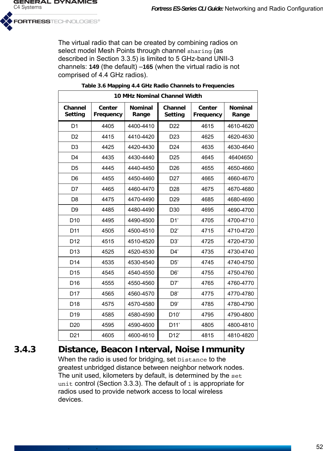
![Fortress ES-Series CLI Guide: Networking and Radio Configuration423.3.5 Channel Sharing NOTE: The channelsharing functionis absent from CLI setoptions and show radiooutput on Mesh Pointsthat do not support it.On ES820-35, ES2440-35, ES2440-3555, ES2440-3444 and ES2440-3444m model Mesh Points that are enabled for FastPath Mesh bridging (described in Section 3.2.2), you can combine certain of their internal radios into a single virtual bridging radio by enabling channel sharing.In certain deployments, such virtual channel-sharing radios can provide superior coverage and/or mobility for network bridging links.NOTE: Changingsharing requiresyou to reboot the MeshPoint (see Section 5.2).Channel sharing is disabled by default.When channel sharing is enabled on dual radio Mesh Points that support the function (the ES820-35 and ES2440-35), Radio 1 and Radio 2 are combined to form a single virtual radio, configured with a single set radio command set. When channel sharing is enabled on four-radio Mesh Points that support it (the ES2440-3555 and ES2440-3444), Radio 2, Radio 3, and Radio 4 are combined in this way.Because a virtual radio created through channel sharing is configured through a single set radio command set, identical configuration parameters are applied simultaneously to all of the radios included in the virtual radio.NOTE: A virtualradio createdthrough channel shar-ing can be used only fornetwork bridging.Like their common radio settings, the single bridging BSSs configured on radios combined through channel sharing must be identically configured. To facilitate this, when you add a new BSS to the virtual radio, the BSS is replicated automatically on each of the radios that comprise the channel-sharing virtual radio. Any subsequent changes to this virtual combined BSS will likewise be extended to the configurations of each actual BSS that comprises it.Channel sharing is limited to Unlicensed National Information Infrastructure (UNII)-3 channels in the 5 GHz-band: 149–165, when not on a 4.4 GHz radio.View the current sharing setting with show sharing. # show sharingDisabledThe default channel sharing setting on all platforms is Disabled, in which state Mesh Point radios function independently. Use set sharing to enable or disable channel sharing on Mesh Point radios. # set sharing disable|enableAs command output informs you, you must reboot the Mesh Point in order for a change to channel sharing to take effect.# set sharing enabled[OK] This change will not take effect until the system is rebooted.# reboot](https://usermanual.wiki/General-Dynamics-Mission-Systems/ES520P/User-Guide-2811717-Page-57.png)
![Fortress ES-Series CLI Guide: Networking and Radio Configuration43Confirm: Reboot device now? [Y|N] y3.4 Individual Radio Settings View the current settings for the Mesh Point’s radio(s) with show radio. Mesh Points with more than one radio display each radio’s configuration information separately:> show radioRadioName: radio1AdminState: disableRadioBand: 802.11gChannelToUse: 1Distance: 1NetworkType: PtMPAntennaGain: 9ShortPreamble: enableBeaconInterval: 100NoiseImmunity: disableChannelLock: disableChannelScan: enableReunification: enableLonelyNode: enableTimeout: 300IgnoreRequest: disableTransmitPower: autoOper Status: downChan Number: 0Chan Frequency: 0 KHzChan Width: 0 MHzChan Max TPO: 0 dBmChan Max EIRP: 0 dBmChan TX Power: 0 dBmRF Kill: Disabled------------------------------------RadioName: radio2AdminState: disableRadioBand: 802.11aChannelToUse: 149Distance: 1NetworkType: PtMPAntennaGain: 9BeaconInterval: 100NoiseImmunity: disableChannelLock: disableChannelScan: enableReunification: enableLonelyNode: enableTimeout: 300IgnoreRequest: disableTransmitPower: autoOper Status: downChan Number: 0Chan Frequency: 0 KHzChan Width: 0 MHzChan Max TPO: 0 dBmChan Max EIRP: 0 dBmChan TX Power: 0 dBmRF Kill: Disabled](https://usermanual.wiki/General-Dynamics-Mission-Systems/ES520P/User-Guide-2811717-Page-58.png)
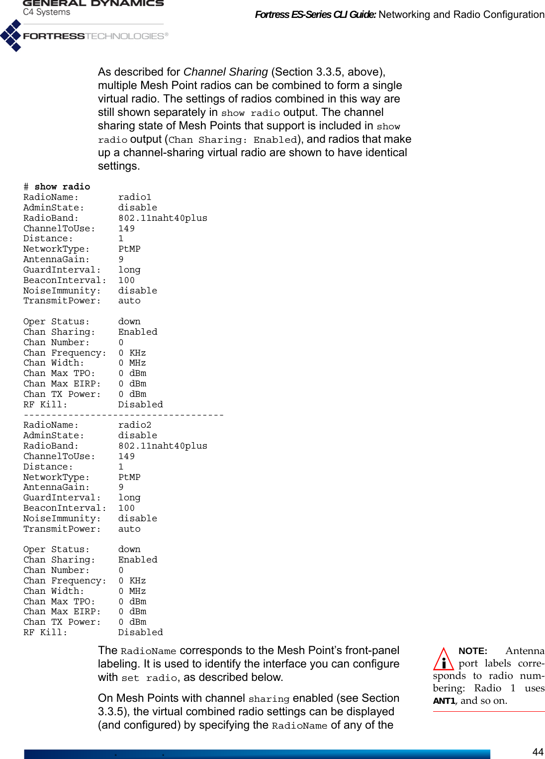
![Fortress ES-Series CLI Guide: Networking and Radio Configuration45radios included in it: radio1 or radio2 on the ES820-35 and ES2440-35; radio2, radio3 or radio4 on the ES2440-3555, ES2440-3444 or ES2440-3444m. Configuration changes made to any of the combined radios will be propagated to all of the radios that make up the virtual radio.AdminState normally displays the radio’s actual operational state and corresponds with the configured value. Under certain circumstances, the state of a Mesh Point radio can become temporarily impossible to determine. In these cases, AdminState displays Unavailable.The conditions that can produce such an AdminState are typically short-lived and will clear immediately. During certain DFS events, however, or in cases where all possible channels are excluded, an AdminState of Unavailable can persist for more extended periods of up to 30 minutes.Below the configured settings, show radio displays current operating details for the radio, among them: Chan Max TPO - the maximum transmit power output in dBm at antenna connector, based on the operating channel and regulatory constraintsChan Max EIRP - the maximum Equivalent Isotropically Radiated Power in dBm, based on the operating channel and regulatory constraintsChan TX Power - the peak transmit power output in dBm on the operating channelConfigure radio settings interactively by entering the set radio command without arguments. The Mesh Point CLI presents one field at a time, and you can either enter a new value for a given field or strike Enter↵ to leave the value unchanged and go on to the next field. The following example shows all of the settings you can administer with set radio. The available values for each setting may vary based on the Mesh Point you are administering. # set radioRadioName (radio1 name of radio interface): radio2AdminState[disable] (enable|disable to set radio interface state):RadioBand[802.11a] (802.11g|802.11nght20|802.11nght40plus|802.11nght40minus|802.11a|802.11naht20|802.11naht40plus|802.11naht40minus to set band):802.11naht40plusGuardInterval[long] (any|long to set short and long, or only long HT40 guard interval (reboot required)):ChannelToUse[149] (channel number to use):Distance[1] (Distance in mile or kilometer):BeaconInterval[100] (25..1000 to set beacon interval in milliseconds):NetworkType[PtMP] (PtMP|PtP to set network type):AntennaGain[5] (0..50 to set antenna gain in dBi):](https://usermanual.wiki/General-Dynamics-Mission-Systems/ES520P/User-Guide-2811717-Page-60.png)
![Fortress ES-Series CLI Guide: Networking and Radio Configuration46TransmitPower (auto|1..33 to set transmit power in dBm):NoiseImmunity[disable] (enable|disable to set noise immunity):MIMO[N] (Y|N to enable MIMO operational mode):ForceSTBC[Y] (Y|N to force STBC transmission):ChannelLock[disable] (enable|disable to set channel lock):ChannelScan[enable] (enable|disable to set channel scan):IgnoreRequest[disable] (enable|disable to set ignore channel change request):Reunification[enable] (enable|disable to set reunification):LonelyNode[enable] (enable|disable to set lonely node):Timeout[300] (60..86400 to set lonely node timeout in seconds):RadioName identifies the radio and cannot be changed. AdminState simply turns the radio on and off.3.4.1 Radio Band, Short Preamble, Guard IntervalNOTE: Radio2cannot be config-ured to use the 802.11b/gfrequency band.RadioBand selects both the frequency band of the radio spectrum a Mesh Point radio will use (for dual band radios) and whether it will use the 802.11n standard for wireless transmission/reception (for radios that support the option).5 GHz and 2.4 GHz OptionsRadios installed as Radio 1 in radio-equipped Fortress Mesh Points (refer to Table 3.1, above) can operate in either the 5 GHz 802.11a frequency band or the 802.11g 2.4 GHz band of the radio spectrum, according to your selection for RadioBand. By default, a dual-band radio installed as Radio 1 in a multi-radio Mesh Point is configured to operate in the 2.4 GHz 802.11g band. The dual-band radio installed in the ES210 is configured to operate in the 802.11a band by default.CAUTION: Use of4.4 GHz radios inthe U.S. without govern-ment approval is strictlyforbidden. In Mesh Points equipped with more than one radio, the additional radio(s) can function in only a single frequency band: the 5 GHz 802.11a band in standard-equipment radios, or the 4.4 GHz band in Mesh Points that support this option.The virtual channel-sharing radio that can be created by combining radios on select model Mesh Points through channel sharing (as described in Section 3.3.5) is limited to the 5 GHz 802.11a frequency band UNII-3 channels.The RadioBand setting is among those subject to the relevant regulatory domain. In some cases, in order to bring the Mesh Point into compliance, dual-band radios could be automatically fixed on the 802.11g band and radios fixed on the 802.11a band could be disabled altogether. Consult your local regulatory authority for the applicable specifications and requirements for radio devices and transmissions.ShortPreamble applies only to 2.4 GHz band operation: # set radioRadioName (name of radio interface, any of radio1|radio2): radio1AdminState (enable|disable to set radio interface state):](https://usermanual.wiki/General-Dynamics-Mission-Systems/ES520P/User-Guide-2811717-Page-61.png)
:ShortPreamble[enable] (enable|disable to set 802.11b short preamble): [...etc.]The short preamble is used by virtually all wireless devices currently being produced, so leaving the setting at its default enabled value is recommended for most network deployments. When ShortPreamble is disabled, connecting devices must use the long preamble, which is still in use by some older 802.11b devices. If the WLAN must support devices that use the long preamble, you must disable ShortPreamble.802.11n OptionsBSSs configured on the radio(s) installed in certain Mesh Point models are additionally capable of 802.11n operation (refer to Table 3.1 on page 38). A Mesh Point radio BSS configured to use the 802.11n standard is fully interoperable with other 802.11n network devices. On 802.11n-capable radios, there are three possible high-throughput (ht) 802.11n options for each frequency band supported on the radio: three for the 5 GHz 802.11na band and three for the 2.4 GHz 802.11ng band, when present:ht20 - 802.11n - High-Throughput 20 MHz, the radio will use only 20 MHz channel widths, while taking advantage of the standard’s traffic handling efficiencies. ht40plus - High-Throughput 40 MHz plus 20 MHz, the radio can use 40 MHz channel widths by binding the selected 20 MHz channel to the adjacent 20 MHz channel above it on the radio spectrum.ht40minus - High-Throughput 40 MHz minus 20 MHz, the radio can use 40 MHz channel widths by binding the selected 20 MHz channel to the adjacent 20 MHz channel below it on the radio spectrum.On ES2440-34m and ES2440-3444m Mesh Points, there is a fourth high-throughput (ht) option for the 4.4 GHz band radios:ht10 - 802.11na - High-Throughput 10 MHz, the radio will use only 10 MHz channel widths while taking advantage of the standard’s traffic handling efficiencies.NOTE: Changingthe radio guard-interval requires youto reboot the Mesh Point(see Section 5.2).When an 802.11n HT40 band setting is specified (802.11naht40plus, 802.11naht40minus, 802.11nght40plus, and 802.11nght40minus), you can specify whether the radio will use only long guard intervals between symbol transmissions (the default), or that the radio can use any (i.e., both long and short) symbol transmission guard intervals.](https://usermanual.wiki/General-Dynamics-Mission-Systems/ES520P/User-Guide-2811717-Page-62.png)
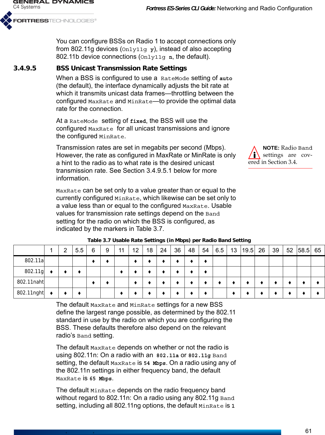
![Fortress ES-Series CLI Guide: Networking and Radio Configuration58NOTE: You mustspecify the ES210Mesh Point’s radio byname: radio1.Add channels to the Static Exclusion List with add xchannel:# add xchannel -radio radio1|radio2 -channel <#>Delete channels from the exclusion list with del xchannel:# del xchannel -radio radio1|radio2 -channel <#> -all You must be logged on to an administrator-level account to change configuration settings (refer to Section 2.2).3.4.9 Radio BSS Settings NOTE: An ES210Mesh Point canalternatively support asingle wireless clientSTA Interface. (Refer toSection 3.4.11.)View the current settings for configured Basic Service Sets (BSSs) with show bss:> show bss No BSS are configured for radio1No BSS are configured for radio2By default there are no BSSs configured on any radio.You can configure up to four BSSs on an individual Mesh Point radio with the add bss command. A maximum total of eight bridging-enabled BSSs can be present on multi-radio Mesh Points: a hardware constraint in dual radio models, but a maximum that must be user-imposed on a four-radio ES2440.A virtual radio created through channel sharing, as described in Section 3.3.5, can support only a single bridging BSS.3.4.9.1 BSS Radio, BSS Name and SSID NOTE: An SSIDcannot be sharedacross multiple BSSs onthe same Mesh Point,unless channel sharingis enabled (refer to Sec-tion 3.3.5).The minimum parameters required to create a new BSS are to identify the radio (-radio) on which it will be created, name the BSS (-name) and provide an SSID of up to 32 characters or enter random with the -ssid switch to generate a random 16-character SSID.Certain interface names and prefixes, such as aux and sta_, are reserved for internal use. If the BSSName you enter is reserved, the Mesh Point CLI will return an error requiring you to modify your entry.# add bss -radio radio1 -name bss1.1 -ssid random[OK]The above example creates a BSS with these default settings:# show bssRadioName: radio1Name: bss1.1Ssid: <randomly generated ssid>EnableWDS: NAdminState: enableAdvertiseSsid: YDropBroadcastProbeReq: NIdleTimeout: 5Only11g: N](https://usermanual.wiki/General-Dynamics-Mission-Systems/ES520P/User-Guide-2811717-Page-73.png)
![Fortress ES-Series CLI Guide: Networking and Radio Configuration59WMM: enableFragThreshold: offRtsThreshold: offDtimPeriod: 1VlanId: 1SwitchingMode: accessVlanAllowAll: YVlanActiveTable: <none>Zone: encryptedUcostOffset: 0Description:802.1X/11i Security: noneRateMode: autoMaxRate: 54MinRate: 1McastRate: 1BssId: 00:14:8c:08:10:91Except for the final line of output (BssId, which displays the BSS’s MAC address), if you specify only the radio, each of the settings shown above can be configured interactively with add bss:# add bss -radio radio1BssName (string for identity): bss1.2Ssid ('random'(randomly generate)|string(32 chars max)): ssid1.2EnableWds[N] (Y|N to allow peer-to-peer connection): yMinimumRSS (-95..0 to set minimum receive signal strength when WDS is enabled):AdminState (enable|disable to set BSS administrative state):AdvertiseSsid (Y|N to advertise or hide SSID in Beacon frame): nDropBroadcastProbeReq (Y|N to drop or respond to broadcast Probe Request frame sent with no SSID):StaIdleTimeout[5] (timeout in minutes before an idle STA is disassociated):Only11g (Y|N to support only 802.11g):RateMode (auto|fixed to set bit-rate adaptation mode):MaxRate (1|2|5.5|11|6|9|12|18|24|36|48|54 to set maximum transmission rate in Mbps):MinRate (1|2|5.5|11|6|9|12|18|24|36|48|54 to set minimum transmission rate in Mbps):WMM (enable|disable to set Wi-Fi Multimedia (WMM) support):FragThreshold (off|256..2345 to set maximum fragment size):RtsThreshold (off|1..2345 to set minimum packet size for RTS/CTS handshake):DtimPeriod (DTIM period in beacon intervals):VlanId (1..4094 to assign the interface to the corresponding VLAN):SwitchingMode (trunk|access to set VLAN mode):AllowAll (Y|N to allow all VLANs in trunk interface):Table (list of active VLAN IDs when allow all is disabled):Zone (clear|encrypted (default is encrypted)):UCostOffset (0..4294967295 to set user-defined offset used to compute virtual interface cost):McastRate (1|2|5.5|11|6|9|12|18|24|36|48|54 to set multicast transmission rate in Mbps):6EnhancedMcast (Y|N to set enhanced multicast):BeaconEncrypt (enable|disable to set WDS Beacon Management frame encryption):WdsMtu (wifi|ether to set mtu size for WDS links):Description (string of description):802.1X/11i Security (none|wpa|wpapsk|wpa2|wpa2psk|wpa2mixed|wpa2mixedpsk):[OK]](https://usermanual.wiki/General-Dynamics-Mission-Systems/ES520P/User-Guide-2811717-Page-74.png)
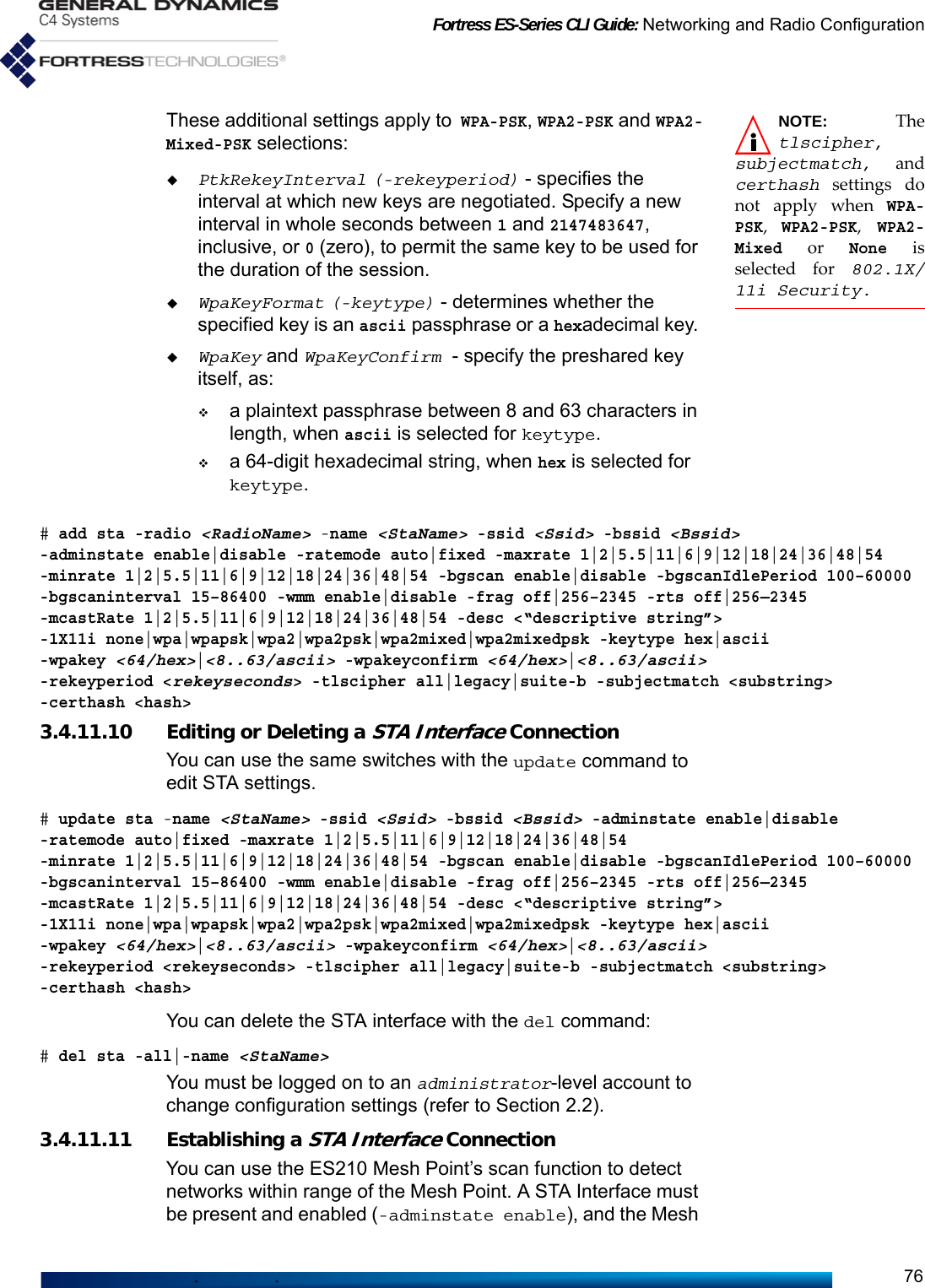
![Fortress ES-Series CLI Guide: Networking and Radio Configuration67-ucost 0–4294967295 -mcastRate 1|2|5.5|11|6|9|12|18|24|36|48|54 -enhancedmcast y|n -wdsmtu wifi|ether -beaconencrypt enable|disable -desc <“descriptive string”> -1X11i none|wpa|wpapsk|wpa2|wpa2psk| wpa2mixed|wpa2mixedpsk -keytype hex|ascii -wpakey <wpaKey> -wpakeyconfirm <wpaKey> -rekeyperiod 0—2147483647 -gmkrekeyperiod 0—2147483647 -radiusperiod 0—2147483647 -strictrekey y|n -reauthperiod 0—2147483647 -preauth y|n 3.4.9.15 BSS Wi-Fi Security ConfigurationBSSs on Fortress Mesh Point radios support WPA (Wi-Fi Protected Access) and WPA2 security.When you choose an 802.1X/11i Security setting other than none (the default), the Mesh Point CLI prompts you for the additional inputs required by the security method you choose.802.1X/11i Security (none|wpa|wpapsk|wpa2|wpa2psk|wpa2mixed|wpa2mixedpsk): wpa2WpaKeyFormat[hex] (hex|ascii to set key string format): hex|asciiWpaKey[""] (WPA key with length 64(hex), 8..63(ascii)):<hexORasciiKey>WpaKeyConfirm[""] (confirm WPA key):<hexORasciiKey>GtkRekeyInterval (group transient key (GTK) rekey interval in seconds): <GTKeyInterval>GmkRekeyInterval (group master key (GMK) rekey interval in seconds): <GMKeyInterval>GtkStrictRekey (Y|N to rekey GTK when a STA leaves the BSS): yReauthInterval (EAPOL reauthentication interval in seconds): <ReAuthInterval>PreAuth[N] (Y|N to set RSN pre-authentication): yWPA (wpa), WPA2 (wpa2) and WPA2-Mixed (wpa2mixed) are enterprise modes of WPA. You can specify wpa or wpa2 to be used exclusively by the BSS, or you can configure it to use either by specifying wpa2mixed.WPA and WPA2 use EAP-TLS (Extensible Authentication Protocol-Transport Layer Security) to authenticate network connections via X.509 digital certificates. For the Mesh Point to successfully negotiate a WPA/WPA2 transaction, you must have specified a locally stored key pair and certificate for the Mesh Point to use to authenticate the connecting device as an EAP-TLS peer, and at least one CA (Certificate Authority) certificate must be present in the local certificate store. Refer to Section 4.2 for guidance on configuring an EAP-TLS key pair and digital certificate.These additional settings apply to wpa, wpa2 and wpa2mixed selections:rekeyperiod (GtkRekyInterval) - specifies the interval at which Group Transient Keys are regenerated. The default is zero (0), which value disables the rekeying function; the same key will be used for the entire session. Specify a new interval in whole seconds between 0 and 2147483647, inclusive.gmkrekeyperiod (GmkRekyInterval) - specifies the interval at which the Group Master Key is are regenerated. The default is 1800. A zero (0) value disables the rekeying function. Specify a new interval in whole seconds between 0 and 2147483647, inclusive.](https://usermanual.wiki/General-Dynamics-Mission-Systems/ES520P/User-Guide-2811717-Page-82.png)
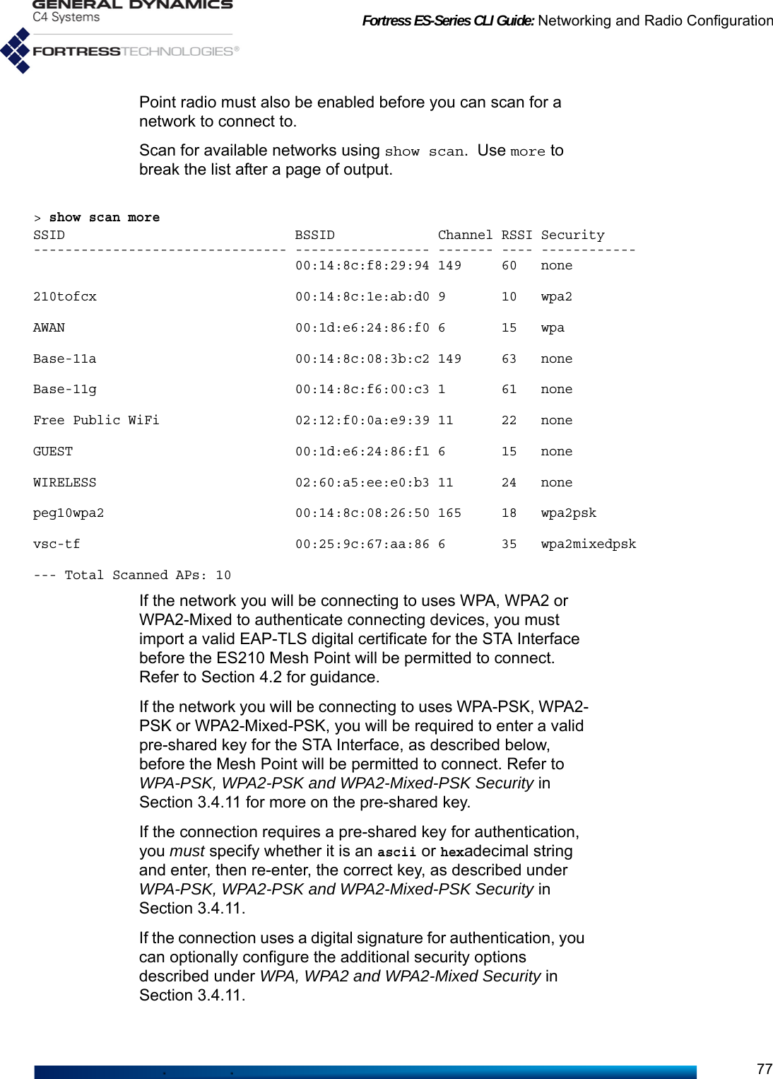
![Fortress ES-Series CLI Guide: Networking and Radio Configuration71WMM: enableFragThreshold: offRtsThreshold: offZone: clearDescription:802.1X/11i Security: noneRateMode: autoMaxRate: 54MinRate: 1McastRate: 1StaId: 00:14:8c:2a:0c:90Operational Status: upAccess Point: 00:00:00:00:00:00You can use update sta to overwrite these parameters, or delete this STA configuration entirely and add a new one with the necessary parameters. 3.4.11.1 STA Radio, Name, SSID and SSID RoamingThe minimum parameters required to create a new STA interface are to identify the radio (-radio) on which it will be created, name the STA (-name) and provide an SSID of up to 32 characters. # add sta -radio radio1 -name station1 -ssid ssid1[OK]Warning: 802.1X/11i Security is set to none and zone is set to clear!The above example creates a STA with these default settings:# show sta RadioName: radio1Name: station1Ssid: ssid1Bssid: 00:00:00:00:00:00AdminState: enableBgScan: disableBgScanIdlePeriod: 250BgScanInterval: 60WMM: enableFragThreshold: offRtsThreshold: offZone: clearDescription:802.1X/11i Security: noneRateMode: autoMaxRate: 54MinRate: 6McastRate: 6StaId: 00:14:8c:f8:18:d0Operational Status: upAccess Point: Not-Associated](https://usermanual.wiki/General-Dynamics-Mission-Systems/ES520P/User-Guide-2811717-Page-86.png)
![Fortress ES-Series CLI Guide: Networking and Radio Configuration72Except for the Zone and the final lines of output (beginning with StaId, which displays the STA’s MAC address), each of the settings shown above can be configured with add sta: # add sta -radio radio1RadioName[radio1] (radio1 name of radio interface): radio1StaName (string for identity): <NewStation>Ssid (string(32 chars max)): NewStationSSIDBssid (MAC address of AP):AdminState (enable|disable to set STA administrative state):RateMode (auto|fixed to set bit-rate adaptation mode):MaxRate (1|2|5.5|11|6|9|12|18|24|36|48|54 to set maximum transmission rate in Mbps):MinRate (1|2|5.5|11|6|9|12|18|24|36|48|54 to set minimum transmission rate in Mbps):BgScan (enable|disable to set background scan support):BgScanIdlePeriod (100..60000 to set background scan idle period in milliseconds):BgScanInterval (15..86400 to set background scan interval in seconds):WMM (enable|disable to set Wi-Fi Multimedia (WMM) support):FragThreshold (off|256..2345 to set maximum fragment size):RtsThreshold (off|1..2345 to set minimum packet size for RTS/CTS handshake):McastRate (1|2|5.5|11|6|9|12|18|24|36|48|54 to set multicast transmission rate in Mbps):Description (string of description):802.1X/11i Security (none|wpa|wpapsk|wpa2|wpa2psk|wpa2mixed|wpa2mixedpsk): wpapskWpaKeyFormat (hex|ascii to set WPA key string format): asciiWpaKey (WPA key with length 64/hex, 8..63/ascii): 00000000WpaKeyConfirm (confirm WPA key with length 64/hex, 8..63/ascii): 00000000PtkRekeyInterval (pairwise transient key (PTK) rekey interval in seconds): 600To create a STA Interface, specify a StaName of up to 254 alphanumeric characters to identify the interface in the Mesh Point configuration. You cannot edit the StaName after the STA Interface has been created. Certain interface names and prefixes, such as aux and sta_ for examples, are reserved for internal use. If the StaName you enter is reserved, the Mesh Point CLI will return an error requiring you to modify your entry.Specify the network SSID to which the ES210 Mesh Point will associate. To determine which networks are available, you can use show scan (refer to Section 3.4.11.11). To disable roaming among multiple APs with the same SSID, in Bssid, specify the MAC address of a single wireless AP to which the STA Interface is permitted to associate.3.4.11.2 STA StateAdminState determines whether the interface is disabled or enabled. A newly added STA is enabled by default. 3.4.11.3 STA Unicast Transmission Rate SettingsWhen a STA Interface is configured to use a RateMode setting of auto (the default), the interface dynamically adjusts the bit rate at which it transmits unicast data frames—throttling](https://usermanual.wiki/General-Dynamics-Mission-Systems/ES520P/User-Guide-2811717-Page-87.png)
![Fortress ES-Series CLI Guide: Networking and Radio Configuration793.5.1 Hostname and IPv4 Settings View basic network properties with the show network command:> show networkCurrent IP values: IPv4 Enabled:y Hostname:hostname IP:192.168.1.9 Netmask:255.255.255.0 DefaultGateway:192.168.1.1 Configured IP values: IP:192.168.1.9 Mask:255.255.255.0 Gateway:192.168.1.1NOTE: The For-tress Mesh Point’sdefault IP address is:192.168.254.254Current IP values are those actually in use on the IPv4 network. Configured IP values are those specified for the Mesh Point (by factory defaults or an administrator). These values can differ briefly between your changing IP values and the new settings taking effect.IPv4 is enabled by default. If the Mesh Point is installed on a network that uses IPv6 exclusively, you can disable IPv4. If the Mesh Point is installed on an IPv4 network, disabling IPv4 prevents you from managing the Mesh Point via IPv4 through the Mesh Point GUI and SSH. Additionally, all IPv4 services, (NTP, SNMP, remote audit logging, external authentication services, etc.) will be disabled. If the Mesh Point’s internal IPv4 DHCP server is enabled, it, too, will be disabled when IPv4 is disabled. Other configurable parameters establish the Mesh Point’s hostname, assign the IPv4 address and subnet mask of the Mesh Point’s management interface and identify the IPv4 default gateway (or router) for the network on which you are installing the Mesh Point. Configure IPv4 network properties for the Fortress Mesh Point with the set network command, as follows:# set network IPv4Enabled[y] (y|n):yHostname[ES-00148c081080]:<hostname>IPaddress[192.168.1.9]:<mngmtIPaddr>Netmask[255.255.255.0]:<subnetmask>DefaultGateway[192.168.1.1]:<dfltGtwy>Confirm: Save and use this configuration? (n|y): y[INFO] This operation may take some time....[OK]The Mesh Point CLI displays the configurable fields for set network one at a time. Enter a new value for the field—or leave the field blank and the setting unchanged—and strike Enter↵, to display the next field. The final confirmation query](https://usermanual.wiki/General-Dynamics-Mission-Systems/ES520P/User-Guide-2811717-Page-94.png)
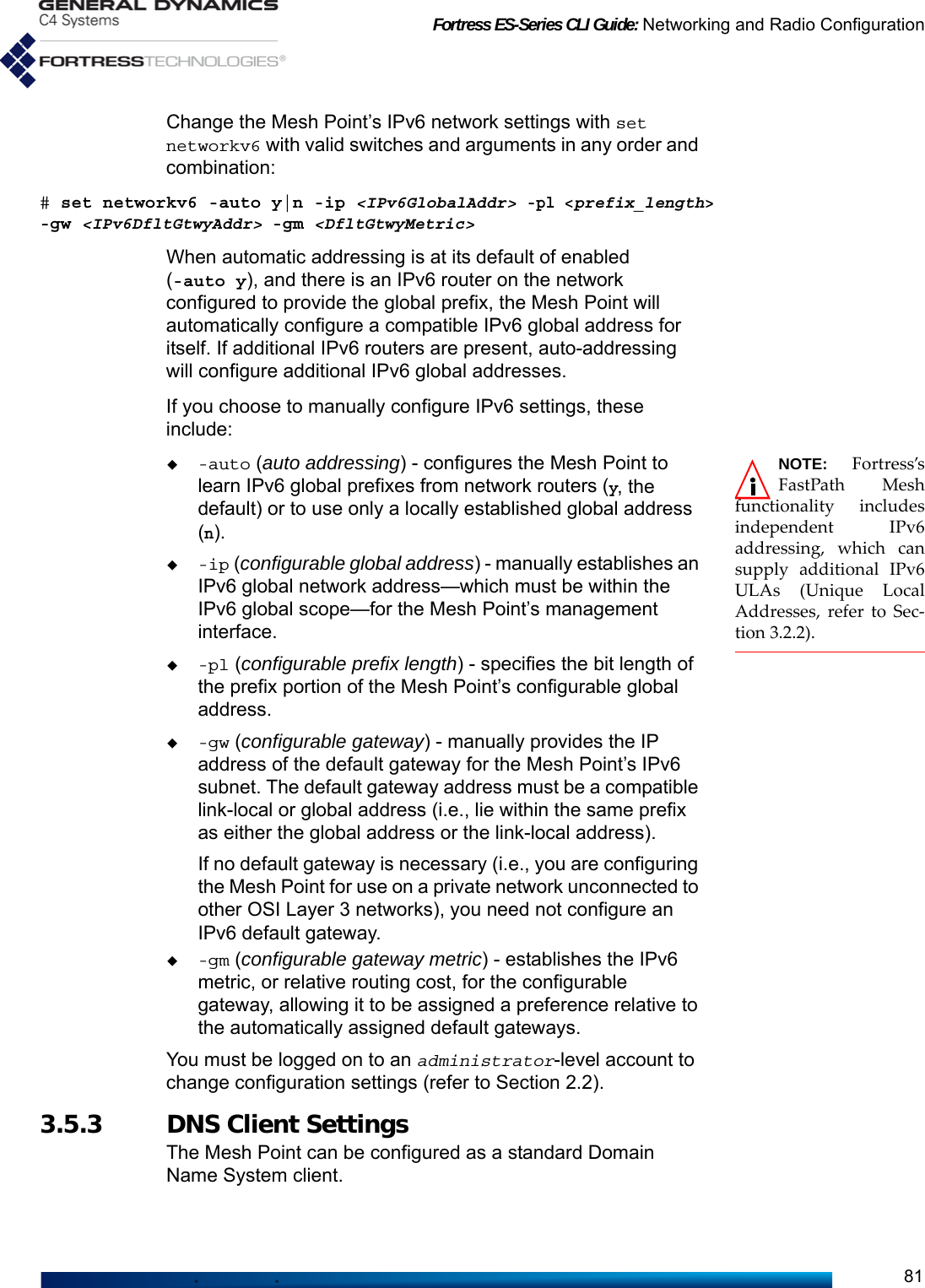
![Fortress ES-Series CLI Guide: Networking and Radio Configuration80displays only when you have entered a value into at least one of the fields presented.Alternatively, you can run set network non-interactively with valid switches and arguments in any order and combination:# set network -enable y|n -h <hostname> -ip <IPv4addr> -nm <subnet_mask> -gw <default_gatewayIP> The Mesh Point CLI returns [OK], when settings are successfully changed, and informs you that there may be brief delay before your change(s) take effect.You must be logged on to an administrator-level account to change configuration settings (refer to Section 2.2).3.5.2 IPv6 Settings NOTE: IncomingICMPv6 (InternetControl Message Proto-col version 6) packetsrequire administrativeaccess. If the adminis-trative IP address ACL(disabled by default) isenabled, it must includethe relevant IPv6addresses. See Section2.2.5 for more detail.Traffic is affected by theper-interface packet fil-ters. If configured, per-interface packet filtersmust include filters topermit ICMPv6 traffic.See Section 4.6.3 formore detail.The Mesh Point supports IPv6, which is always enabled. When an IPv6 router is present on the network and Automatic Address is Enabled on the Mesh Point (the default), the Mesh Point will be automatically provided a compatible IPv6 Global Address and Prefix Length. Any network IPv6 routers configured to do so will additionally supply their own addresses as the Mesh Point’s IPv6 Default Gateways.View the Mesh Point’s current IPv6 configuration with show networkv6:> show networkv6Current IPv6 values: Automatic Address Enabled:n Global Address:2001:DB8:0:0:0:0:0:2 Global Address Prefix Length:128 Link Local Address:FE80:0:0:0:214:8CFF:FE08:1080 Other Addresses:FD00:0:8895:8895:214:8CFF:FE08:1980/64 2099:0:0:0:214:8CFF:FE08:1980/64 Default Gateways:FE80:0:0:0:0:0:0:1 (metric=47) 2001:0:0:0:0:0:0:1 (metric=23)Configured IPv6 values: Global Address:2001:DB8:0:0:0:0:0:2 Global Address Prefix Length:128 Gateway:FE80:0:0:0:0:0:0:1 Default Gateway Metric:1024Prefix lengths for Other Addresses are shown after the addresses, and the metrics for all Default Gateways are shown in parentheses).You can choose to allow all IPv6 settings to be automatically configured on the Mesh Point, opt to manually configure the global address and IPv6 gateway/metric, or use both manually and automatically configured global addresses.](https://usermanual.wiki/General-Dynamics-Mission-Systems/ES520P/User-Guide-2811717-Page-95.png)
![Fortress ES-Series CLI Guide: Networking and Radio Configuration82NOTE: Mesh Pointsoftware alsoincludes a standardDNS service (Section3.8), and FP Mesh pro-vides name resolutionwithin the mesh inde-pendent of any DNSservice (Section 3.2.2).View the current DNS client configuration with show:> show dns-clientDomain: ftimesh.localPreferred DNS server: UnknownAlternate DNS server: UnknownConfigure DNS settings with set, which can be used interactively:# set dns-clientDomain: <domainName>Preferred IP: <preferredDNSsvrIPaddrs>Alternate IP: <alternateDNSsvrIPaddrs>The Mesh Point CLI displays the configurable fields for set dns one at a time. Enter a new value for the field—or leave the field blank and the setting unchanged—and strike Enter↵, to display the next field.Alternatively, you can run set dns non-interactively with valid switches and arguments in any order and combination:# set dns-client -d <domainName> -ip1 <preferredDNSsvrIPaddrs> -ip2 <alternateDNSsvrIPaddrs>The Mesh Point CLI returns [OK] when settings are successfully changed.You must be logged on to an administrator-level account to change configuration settings (refer to Section 2.2).3.6 Time and Location Configuration You should either set the Mesh Point’s internal clock at installation, or enable and configure its NTP (Network Time Protocol) function.3.6.1 System Date and Time View Mesh Point date and time settings with the show clock command:> show clockSun Jul 15 23:39:39 UTC 2001You can use the -local switch to show the local time rather than the default TimeZone, UTC (Universal Time Coordinated):> show clock -localTue Sep 30 23:08:23 ETD 2008Set system date and time on the Fortress Mesh Point, using the twenty-four-hour clock and numerical date, through the set clock command, as follows:# set clock# set clock -h 14 -m 21 -s 46 -M 12 -D 12 -Y 2010](https://usermanual.wiki/General-Dynamics-Mission-Systems/ES520P/User-Guide-2811717-Page-97.png)
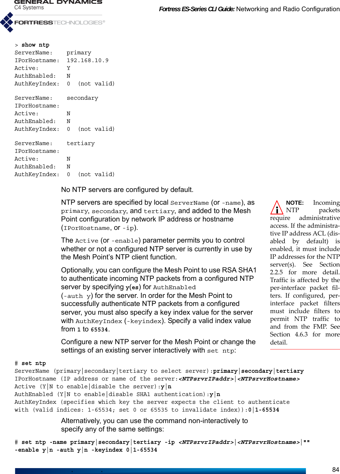
![Fortress ES-Series CLI Guide: Networking and Radio Configuration83The set clock command returns the Mesh Point’s current date and time values, which you can edit and re-enter: use the left/right arrow keys to navigate displayed fields, backspace over current values or overwrite them. When you finish typing in new values, strike Enter↵ to save them. The Mesh Point CLI returns [OK] when settings are successfully changed.Alternatively, you can run set clock non-interactively with valid switches and arguments, as shown below.# set clock -h <hrs> -m <mins> -s <secs> -M <M> -D <D> -Y <YYYY>To set the Mesh Point’s internal clock in local time rather than UTC, use the -local switch with set clock.# set clock -local# set clock -local -h 10 -m 21 -s 46 -M 12 -D 12 -Y 2008The Mesh Point CLI returns [OK] when settings are successfully changed.You must be logged on to an administrator-level account to change configuration settings (refer to Section 2.2).3.6.2 Time Zone View the current time zone setting with show:> show timezone America/New_YorkThe set command is used to change the time zone setting interactively, displaying allowable country|territory values for you to enter, and then allowable zone values. Entries are case-sensitive: enter your choice exactly as it appears in the list.# set timezoneAfrica, America, Asia, Atlantic, Australia, Brazil, Canada, Europe, Indian, Mexico, Mideast, Pacific, US,--> Enter timezone|continent|country|territory name: USAlaska, Aleutian, Arizona, Central, East-Indiana, Eastern, Hawaii, Indiana-Starke, Michigan, Mountain, Pacific, Samoa--> Enter second level timezone|country|state|city|territory name: US/EasternThe Mesh Point CLI returns [OK] when settings are successfully changed.You must be logged on to an administrator-level account to change configuration settings (refer to Section 2.2).3.6.3 NTP Client Configuration The Mesh Point supports configuration with up to three Network Time Protocol (NTP) servers.View the current NTP configuration with show ntp:](https://usermanual.wiki/General-Dynamics-Mission-Systems/ES520P/User-Guide-2811717-Page-98.png)
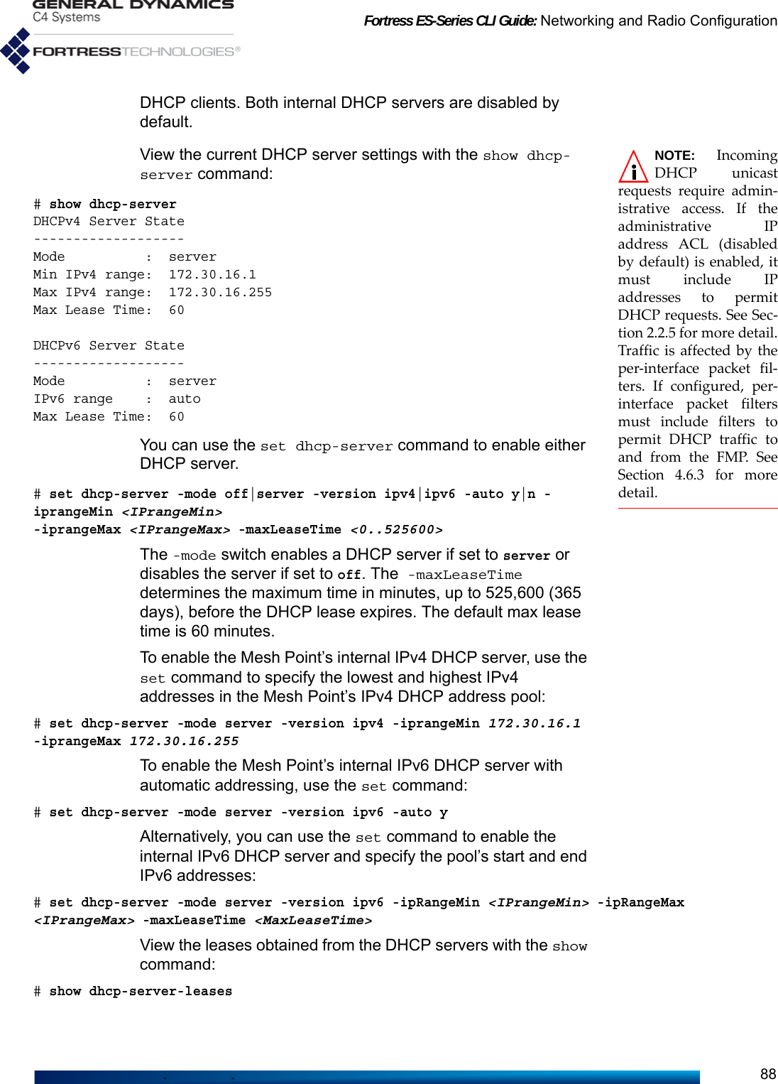
![Fortress ES-Series CLI Guide: Networking and Radio Configuration89[ Active DHCP LEASES ]Mac leaseExpiry hostname ipAddress gateway----------------- ---------------------------- --------------------------- ------------- ---------------------00:0c:29:8e:ac:0a Wed Mar 24 19:34:49 2010 UTC FD00:0:8895:8895:20C:29FF:FE8E:AC0A 00:0c:29:8e:ac:14 Wed Mar 24 19:25:07 2010 UTC vmclient12.gdfortress.com 172.30.50.204 172.30.50.1You must be logged on to an administrator-level account to change configuration settings (refer to Section 2.2).3.8.2 Enabling DNS Servers and Adding External DNS ServersNOTE: IncomingDNS queriesrequire administrativeaccess. If the administra-tive IP address ACL (dis-abled by default) isenabled, it must includeIP addresses to permitDNS queries. See Section2.2.5 for more detail.Traffic is affected by theper-interface packet fil-ters. If configured, per-interface packet filtersmust include filters topermit DNS traffic toand from the FMP. SeeSection 4.6.3 for moredetail.Internal DHCP services use the internal DNS server (see below) and the locally configured DNS client settings and domain name (refer to Section 3.5.3).View the current DNS client settings with the show command:# show dns-clientDomain: gdfortress.comPreferred DNS server: 10.2.2.35Alternate DNS server: UnknownThe Mesh Point’s internal DNS server is enabled by default. To enable or disable DNS services, use the set command:# set dns-server -enable y|nDetermine whether the DNS server is enabled with the show command:# show dns-serverDNS Server State: EnabledYou can use the add dns-entry command to map a DNS name to an IP address.# add dns-entry -name <DNSName> -ip <DNSIPAddr>NOTE: Fortress’sFastPath Meshfunctionality includesautomatic RFC-4193IPv6 addressing inde-pendent of network IPv6DHCP services (see Sec-tion 3.2.2).View the current DNS servers with the show command:# show dns-entryIpAddress Domain Name Type----------------------------- ---------------- --------- -------172.30.16.237 gdfortress.com ESnnn-237 selfFE80:0:0:0:214:8CFF:FEF8:18C0 gdfortress.com ESnnn-237 self172.30.16.240 gdfortress.com ExtDNS1 staticTotal 3 EntriesYou can delete a single DNS entry by name or all added DNS entries:# del dns-entry -all|-name <DNSName> -ip <DNSIPAddr>You must be logged on to an administrator-level account to change configuration settings (refer to Section 2.2).](https://usermanual.wiki/General-Dynamics-Mission-Systems/ES520P/User-Guide-2811717-Page-104.png)
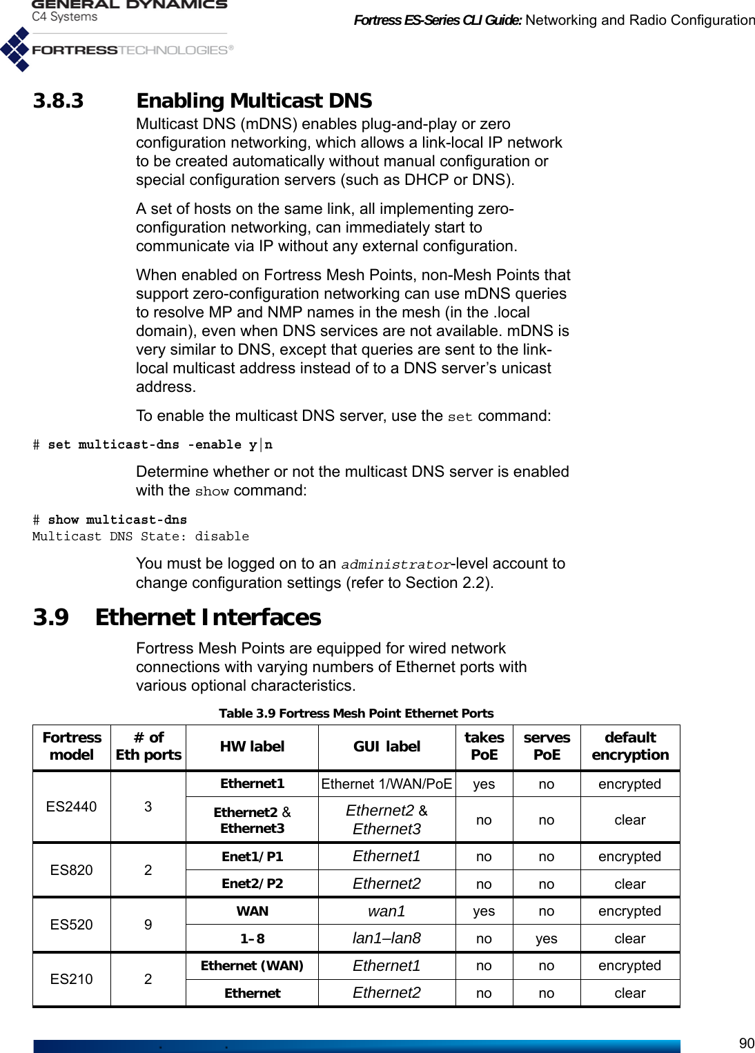
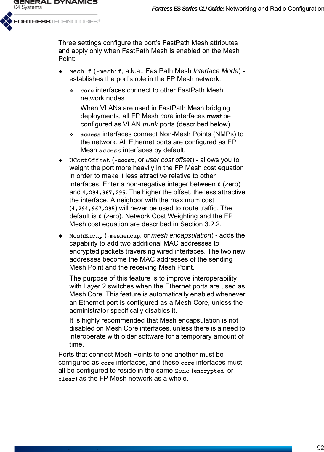
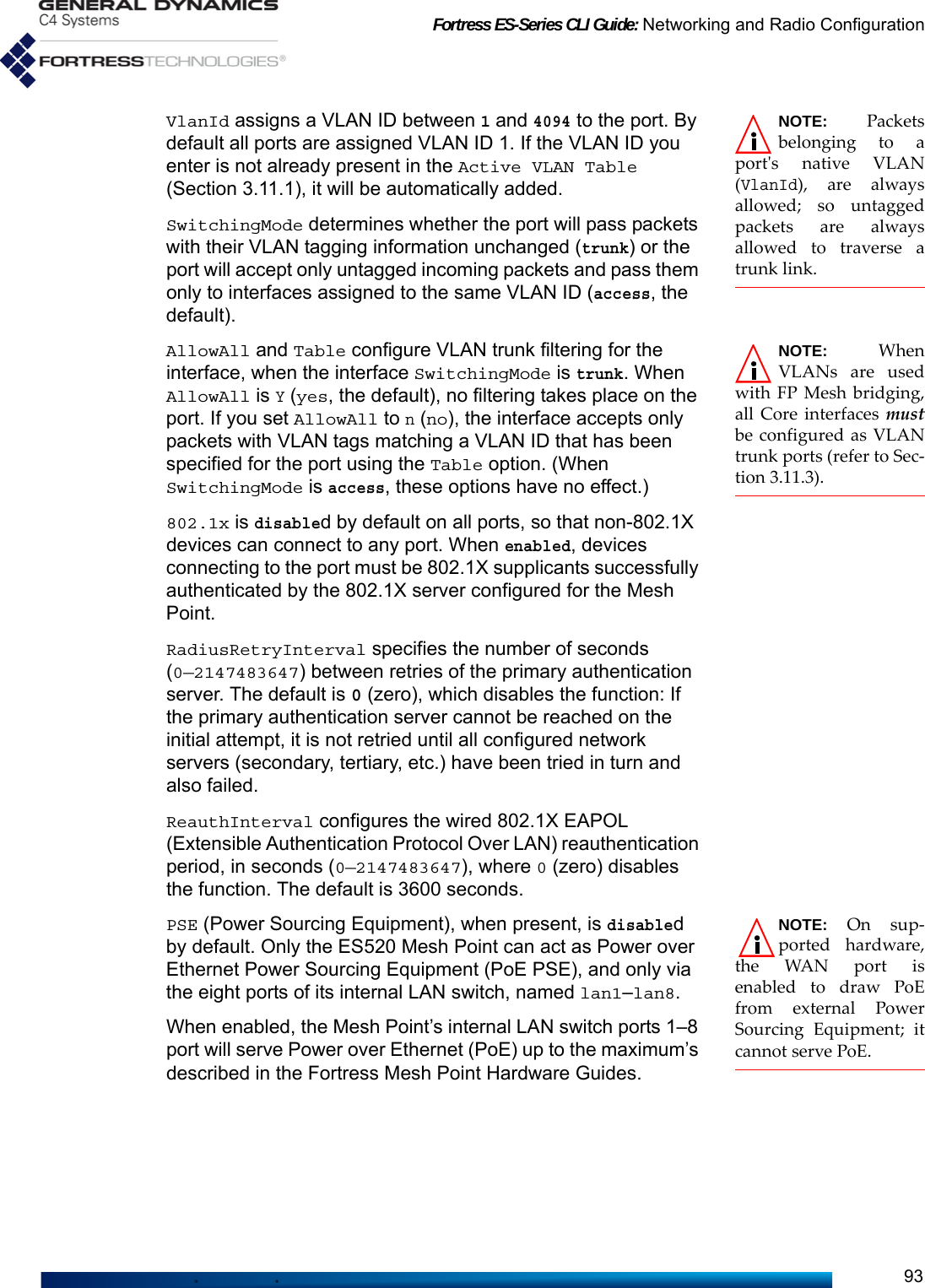
![Fortress ES-Series CLI Guide: Networking and Radio Configuration91View the current configuration of the Mesh Point’s Ethernet interfaces (followed by status information and statistics not shown in this example) with show interface. The output for this command varies based on the number and type of interfaces on the Mesh Point (refer to Table 1.1 on page 3):# show interface[CONFIGURED INFO] Switching UCost Enable TrafficName Mode VlanId Mode Duplex Speed 8021x Zone MeshIf Offset MeshEncap QoS Class--------- ------- ------ --------- ------ ----- ----- --------- ------ ------ --------- ------ -------Ethernet1 enabled 1 access auto auto N encrypted access 0 N N lowEthernet2 enabled 1 access auto auto N clear access 0 N N low[STATUS INFO]Name Link Duplex Speed Collisions--------- ---- ------ ----- ----------Ethernet1 down half 10 0Ethernet2 up full 100 0[STATISTIC INFO]Name Type State InBytes InPackets InErrTotal OutBytes OutPackets OutErrTotal--------- ------- -------------- ---------- --------- ---------- ---------- ---------- -----------Ethernet1 wired disabled 0 0 0 0 0 0Ethernet2 wired forwarding_all 70804 1079 40 32816 587 0The Name of the interface cannot be changed, and correlates to the hardware port. Refer to Table 3.9 to find the appropriate port name. Use it (with the -name switch) to identify the interface you want to configure with set interface:# set interface -name <InterfaceName>Mode[enabled] (enabled|disabled to set administrative mode):Zone[clear] (clear|encrypted):MeshIf[access] (core|access(default) to make interface Mesh Net or not (e.g. Access)):UCostOffset[100] (user-defined offset used in computing interface cost [0..4294967295], default is 0)MeshEncap[N] (Y|N to enable|disable Mesh encapsulation on Mesh core interface):VlanId[1] (Vlan ID for untagged PDUs [1..4094]):SwitchingMode[access] (trunk|access to set switching mode):AllowAll[Y] (Y|N to allow all VLANs in trunk interface):Table (list of active VLAN IDs when allow all is disabled):8021x[N] (Y|N to enable or disable IEEE 802.1X port authentication):RadiusRetryInterval[0] (maximum interval in seconds before primary RADIUS server is tried again):ReauthInterval[3600] (EAPOL reauthentication interval in seconds):PSE[disable] (enable|disable to enable or disable PoE PSE):AutoNegotiation[N] (Y|N for auto negotiation):EnableQoS[N] (Y|N to enforce traffic class priority, override 802.1p):TrafficClass[low] (low|medium|high|critical to set traffic class priority):DuplexMode (half|full): SpeedValue (10|100 to set speed when autoNegotiation is off):Mode enables/disables the port itself. Ports are enabled by default). Zone places the port in the Mesh Point’s clear or encrypted zone. Refer to Table 3.9 for the default clear/encrypted values for each port.](https://usermanual.wiki/General-Dynamics-Mission-Systems/ES520P/User-Guide-2811717-Page-106.png)
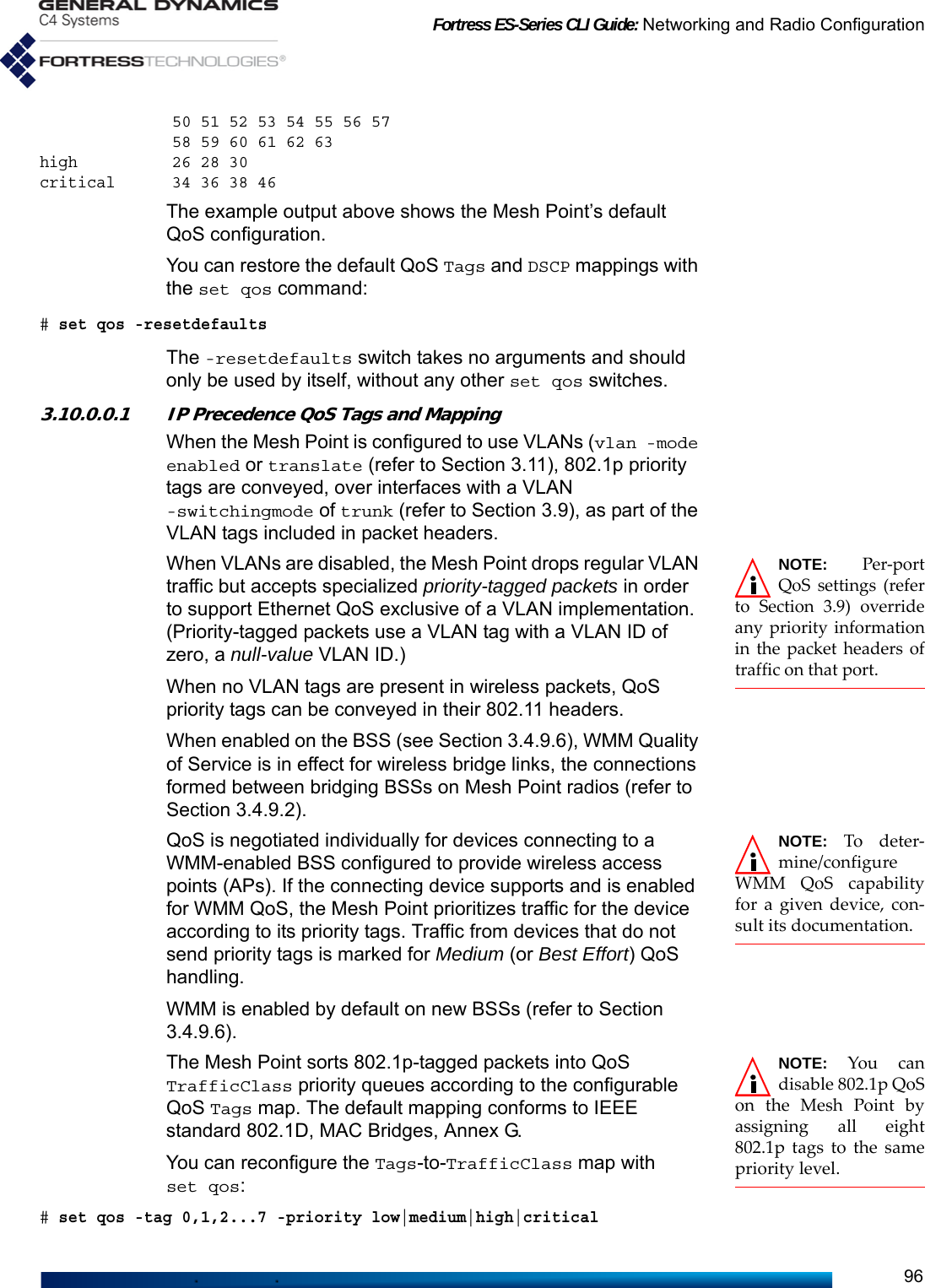
![Fortress ES-Series CLI Guide: Networking and Radio Configuration94NOTE: The ES2440supports a portspeed of 1000 Mbpswhen AutoNegotia-tion is enabled (y), butyou cannot specify thatvalue for Speed.AutoNegotiation is enabled (y) by default on all ports. If you disable AutoNegotiation, specify the Duplex mode and negotiation Speed. Duplex determines whether the port will allow only Full duplex communication or only Half duplex communication. Speed determines the speed at which the port will transmit and receive data 10 Mbps or 100 Mbps. When QoS is disabled (EnableQoS:n), the port passes packets tagged with IEEE 802.1p Quality of Service information, as tagged, according to the Mesh Point’s four-class 802.1p QoS implementation (Section 3.10). This is the default setting on all ports. Enabling QoS on a given port (EnableQoS:y) configures the port to apply its assigned Quality of Service class to all packets received on the port, overriding any IEEE 802.1p tag already present. When you enable QoS on a port, you can then assign the port to—and therefore apply to all traffic passed on the port—one of the four available service classes: TrafficClass low, medium, high or critical. Alternatively, you can use the set interface command with valid switches and arguments to configure any of the above settings on an individual Ethernet port:# set interface -name <InterfaceName> -adminstate enable|disable -zone clear|encrypted -meshif core|access -ucost 0–4294967295 -meshencap Y|N -vlanID 1-4094 -switchingmode trunk|access -8021x y|n -radiusperiod 0—2147483647 -reauthperiod 0—2147483647-pse enable|disable -autoneg y|n -duplex half|full -speed 10|100 -QoSAdmin y|n -priority low|medium|high|critical3.10 Quality of Service The Mesh Point supports Quality of Service (QoS) traffic expediting standards, including IEEE 802.1p (Traffic Class Expediting), the WMM® (Wi-Fi Multimedia) subset of IEEE 802.11e (QoS for Wireless LAN), and the more recent Differentiated Services (DiffServ) model described in RFC 2474 (Definition of the Differentiated Services Field [DS Field] in the IPv4 and IPv6 Headers) and RFC 2475 (An Architecture for Differentiated Services).Incoming network traffic is sorted for expediting into one of four QoS TrafficClass priority queues: critical - packets in the critical queue are delivered ahead of packets at all other QoS levels.high - packets in the high queue are delivered after critical packets and ahead of packets in lower-level queues.medium - packets in the medium queue are delivered on a Best Effort basis: after those in higher-level queues, but ahead of low priority traffic.](https://usermanual.wiki/General-Dynamics-Mission-Systems/ES520P/User-Guide-2811717-Page-109.png)

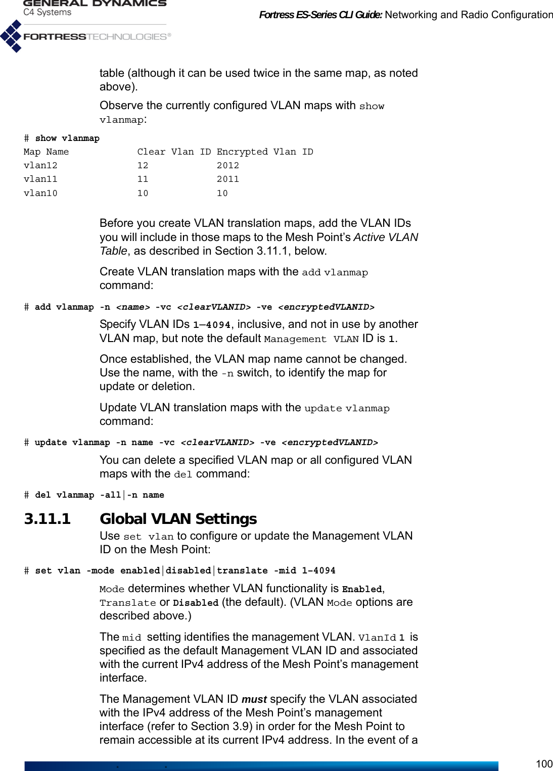
![Fortress ES-Series CLI Guide: Networking and Radio Configuration101mismatch between the IPv4 address associated with the Management VLAN ID and that of the Mesh Point’s management interface, you can restore remote management access to the Mesh Point only by reconfiguring it via a direct physical connection to its Console port.Additionally, when VLANs are enabled, the Mesh Point’s internal DHCP and DNS services (described in Section 3.8) are accessible only in the management VLAN. The Mesh Point will not provide DHCP and DNS services on VLANs other than the one associated with the Management VLAN ID. Use add vlan to include additional VLANs in the Active VLAN Table:# add vlan -id 1–4094 -ip <IPv4Addr> -nm <subnetMask> NOTE: VLAN IDs0 and 4095 arereserved for internaluse.The -id switch specifies a VLAN ID number, from 1–4094, inclusive, for the VLAN.The -ip switch associates the VLAN with a specific Unicast IPv4 address. Alternatively, you can associate the VLAN with an IP Address of 0.0.0.0. This will prevent IGMP queries from being sent on the VLAN, in which cases IPv4 multicast listeners on the VLAN may not be automatically discovered. VLANs configured in this manner will appear as Not Configured in show vlan. Use the -nm switch to enter the IPv4 subnet mask associated with this VLAN. To change the IP address associated with a VLAN, use update:# update vlan -id <vlanID> -ip <IPv4Addr> -nm <subnetMask>View the current VLAN configuration with show:> show vlanMode: enabledManagement VLAN: 1[ACTIVE VLAN ID TABLE]ID IPv4 Address IPv4 Subnet Mask-- ------------ ----------------1 192.168.1.6 255.255.255.02 Not Configured 255.255.255.03 Not Configured 255.255.255.0[VLAN STATISTICS]ID EncryptRx EncryptTx ClearRx ClearTx KeyExchangeRx KeyExchangeTx WllsRx WllsTx VlanMgmt-- --------- --------- ------- ------- ------------- ------------- ------ ------ --------1 0 0 142 35 0 0 0 0 02 0 0 0 0 0 0 0 0 03 0 0 0 0 0 0 0 0Delete one VLAN or all VLANs from the Mesh Point configuration by ID number with del vlans:# del vlan -id <vlanID>|all](https://usermanual.wiki/General-Dynamics-Mission-Systems/ES520P/User-Guide-2811717-Page-116.png)
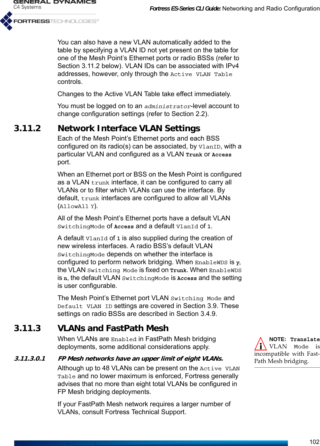
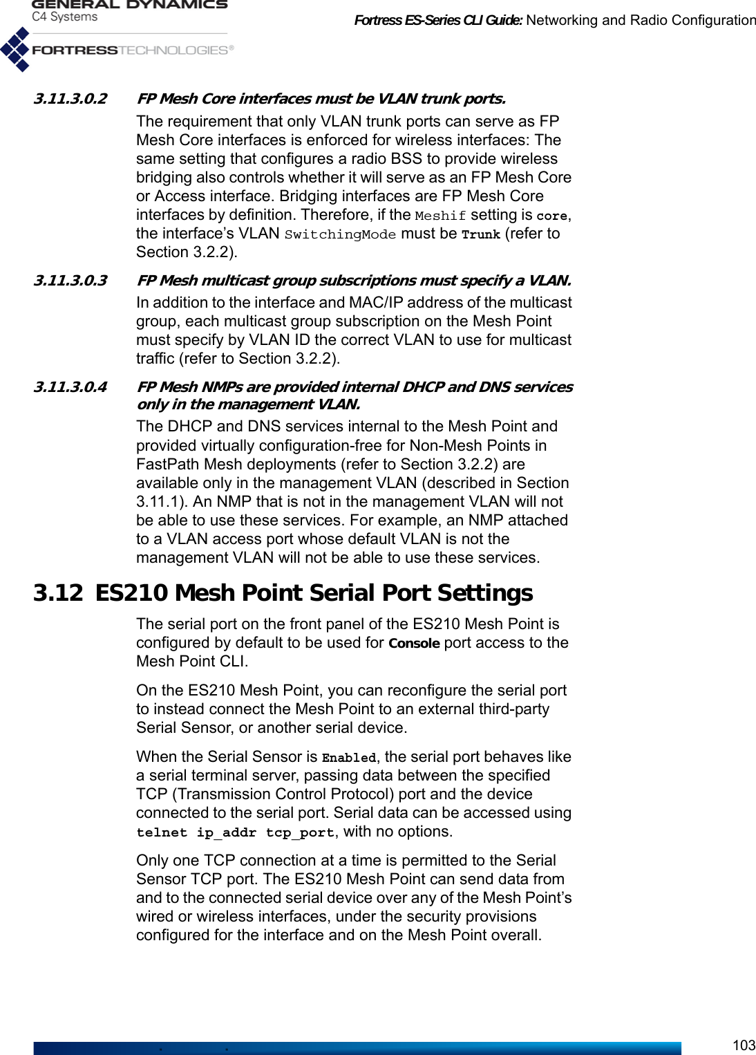
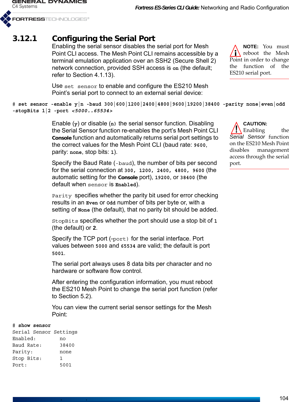
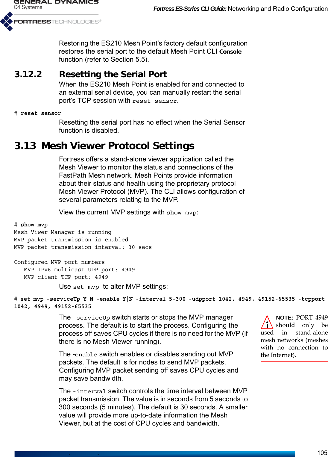

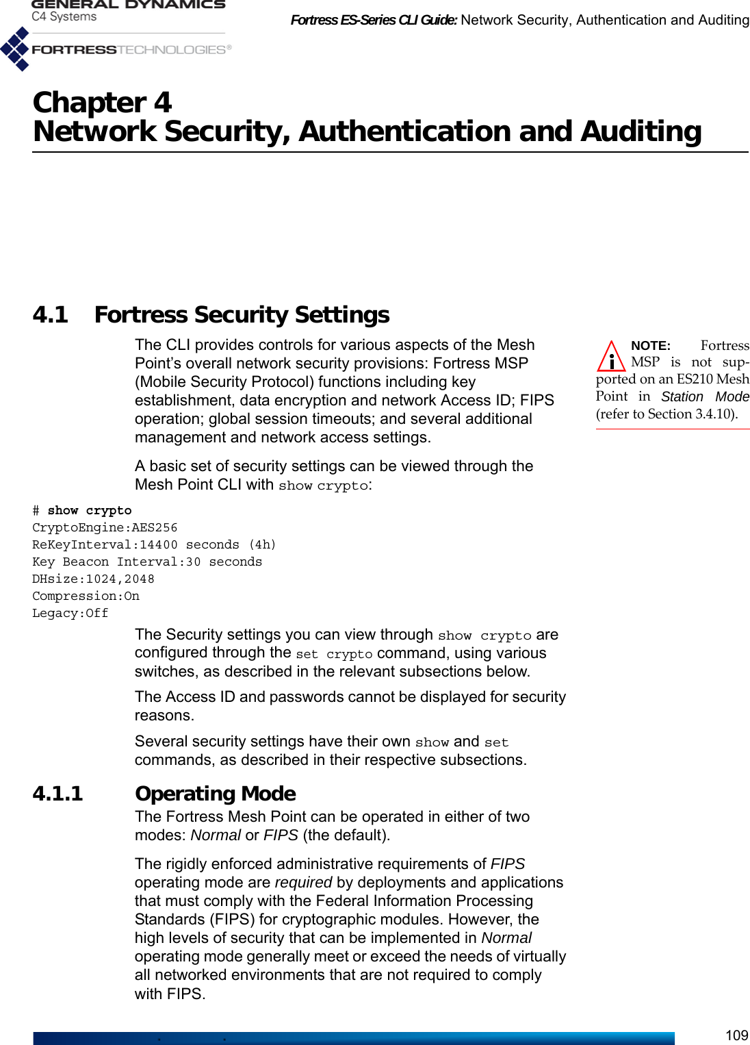
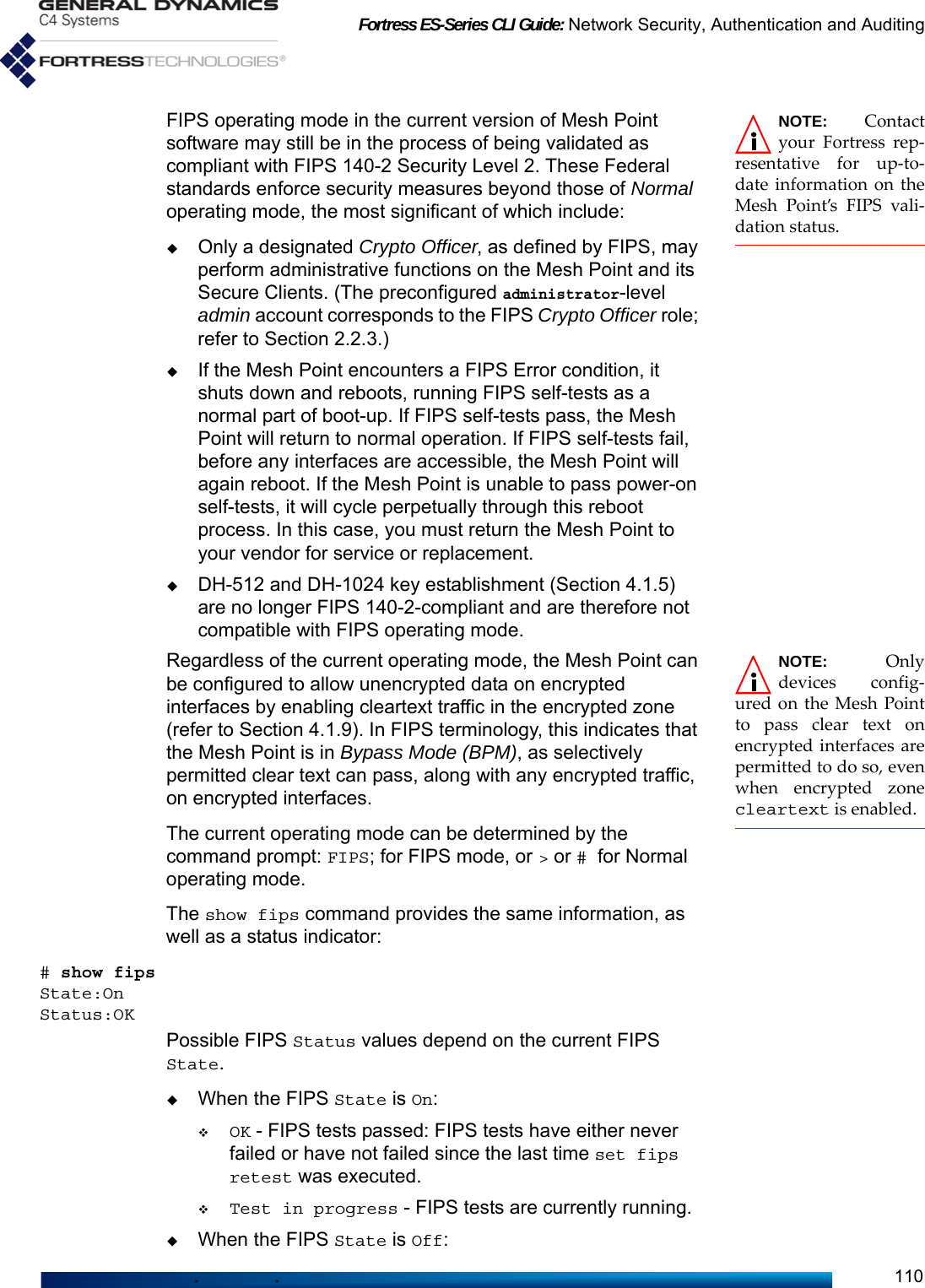
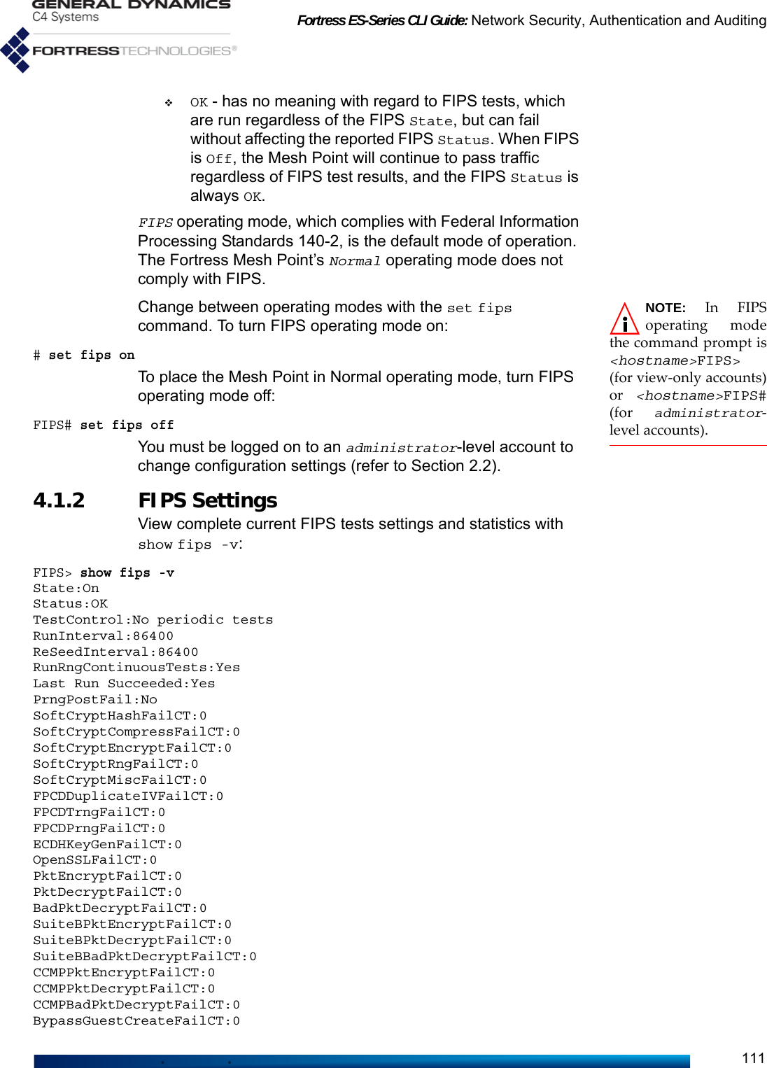
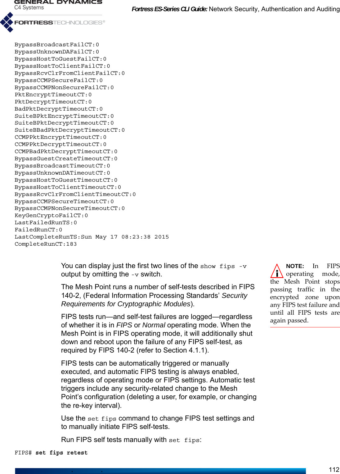
![Fortress ES-Series CLI Guide: Network Security, Authentication and Auditing113As required by FIPS 140-2, if a FIPS test fails, the failure persists—through reboots and software upgrades—until the Mesh Point again passes the full battery of FIPS tests. In FIPS operating mode, If the Mesh Point fails a FIPS test, it automatically reboots. If the failure persists through the boot cycle, the Mesh Point continues to reboot until the test passes or the Mesh Point is taken out of service. In addition to the FIPS tests triggered regularly on the Mesh Point, you can configure additional, periodic FIPS testing, with set fips:FIPS# set fips periodic|noperiodicPeriodic FIPS testing is disabled by default (noperiodic). When periodic tests are enabled, they run at the FIPS-test run-interval specified using set fips with the -r switch. The default is 86,400 seconds, or 24 hours.You can also configure the interval at which the random number generator is reseeded using set fips with the -s switch. The default is 86,400 seconds, or 24 hours.FIPS# set fips -r <RunIntervalSeconds> -s <SeedIntervalSeconds>With set fips you can also configure whether the Mesh Point’s random number generator test will be run routinely (it is enabled by default):# set fips rngtestRngContinuousTests? [N|Y]This command can be run only interactively. The Mesh Point CLI displays RngContinuousTests? and you can enter your selection—or leave the field blank and the setting unchanged—and strike Enter↵.The Mesh Point CLI returns [OK] when settings are successfully changed. You cannot turn off FIPS random number generator tests when the Mesh Point is in FIPS operating mode.You must be logged on to an administrator-level account to change configuration settings (refer to Section 2.2).4.1.3 MSP Encryption Algorithm The encryption algorithm determines how the Mesh Point encodes data. All Secure Clients logging on through the Fortress Mesh Point, and other Mesh Points with security associations to this one, must use the same encryption algorithm. View the encryption algorithm (among other security settings) in effect on the Mesh Point with show crypto (shown in Section 4.1).](https://usermanual.wiki/General-Dynamics-Mission-Systems/ES520P/User-Guide-2811717-Page-127.png)
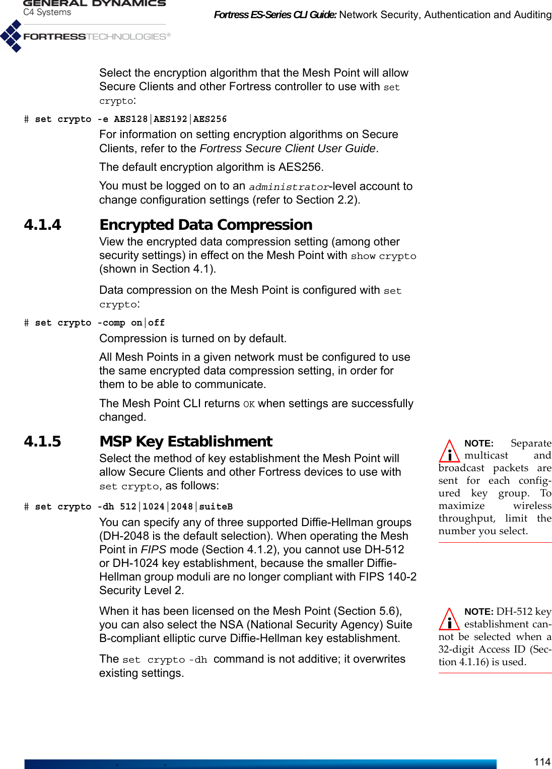
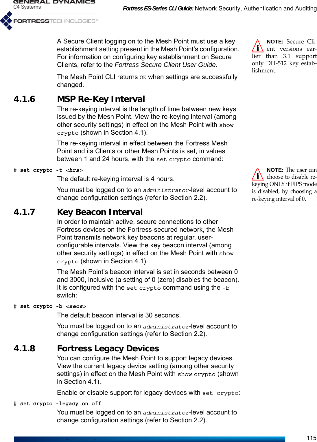
![Fortress ES-Series CLI Guide: Network Security, Authentication and Auditing118You can turn off GUI access to the Mesh Point altogether by disabling the user interface. The Mesh Point GUI is enabled by default.You can view the current GUI access setting with show gui:> show guiStatus: OnSSL Private Key: ssl_auto_keyRequire client certificate: noAuto Logon client certificate: noIf you want to limit access to the Fortress Mesh Point exclusively to the Mesh Point CLI, you can disable the Mesh Point GUI, as follows:# set gui offTo re-enable the Mesh Point GUI, enter:# set gui onYou can use the -key switch to indicate or change the private key and client certificate to use for SSL sessions:# set gui -key <keyname>Use the -nokey switch to clear the encryption key currently in use:# set gui -nokey If you want to require the GUI client to present a digital certificate to be authenticated before being permitted access, set -requireClientCertificate to enabled.:# set gui -requireClientCertificate enabled[OK] Note: You must restart the controller for client authentication changes to take effect.Turn this functionality back off with the same command: # set gui -requireClientCertificate disabled[OK] Note: You must restart the controller for client authentication changes to take effect.NOTE: When SSOis configured, ifthe Mesh Point is alsoconfigured to authenti-cate with a RADIUSserver rather than withlocal authentication, theuser must enter user-name and password thefirst time the certificateCommon Name usertries to logon. This isnecessary in order topopulate the localauthentication cache.As the prompt informs you, you must reboot the Mesh Point in order to put a change to -requireClientCertificate into effect: refer to Section 5.2.If you want to automatically log in GUI users who have presented a valid certificate, without requiring them to enter user name and password, set -clientCertificateSignOn to enabled:# set gui -clientCertificateSignOn enabledYou must also require the GUI client to present a digital certificate; -requireClientCertificate must be enabled if -clientCertificateSignOn is enabled. This feature is most useful when Common Access Cards (CAC) are used, but any X509 client certificate may be used as long as the Common Name (CN) contains the user name.](https://usermanual.wiki/General-Dynamics-Mission-Systems/ES520P/User-Guide-2811717-Page-132.png)
![Fortress ES-Series CLI Guide: Network Security, Authentication and Auditing120# del sshkey -allTo delete a specific SSH public key:# del sshkey -name <SSHPublicKeyName>You must be logged on to an administrator-level account to change configuration settings (refer to Section 2.2).4.1.14 Blackout Mode NOTE: You canalso toggle theMesh Point’s BlackoutMode in the Mesh PointGUI (described in theGUI Guide), and withchassis controls on someMesh Point models(covered in their respec-tive Hardware Guides).The Blackout Mode setting on the Fortress Mesh Point globally turns all chassis LEDs on and off. When Blackout Mode is Enabled, none of the Mesh Point’s LEDs will illuminate for any reason—except for a single, initial blink (green) of less than half a second, at the beginning of the boot process in some models. When Blackout Mode is Disabled (the default), the LED indicators function normally.View the current blackout mode with show blackout:> show blackoutOnEnable/disable blackout mode with the set command:# set blackout on[OK]You must be logged on to an administrator-level account to change configuration settings (refer to Section 2.2).4.1.15 Allow Cached Credentials When a device’s session times out, the device is required to renegotiate encryption keys in order to reconnect to the network. When the Mesh Point is configured to permit cached authentication credentials (the default), Secure Clients are allowed to transparently reauthenticate, without user intervention. You can force Secure Client users to re-enter their credentials whenever their sessions are reset by disabling the cachedauth setting.View the current cached credentials settings with show cachedauth:> show cachedauthClientReAuth: NEnable/disable permission for Secure Clients to reauthenticate with cached user credentials with set cachedauth:# set cachedauth y|nYou must be logged on to an administrator-level account to change configuration settings (refer to Section 2.2).](https://usermanual.wiki/General-Dynamics-Mission-Systems/ES520P/User-Guide-2811717-Page-134.png)
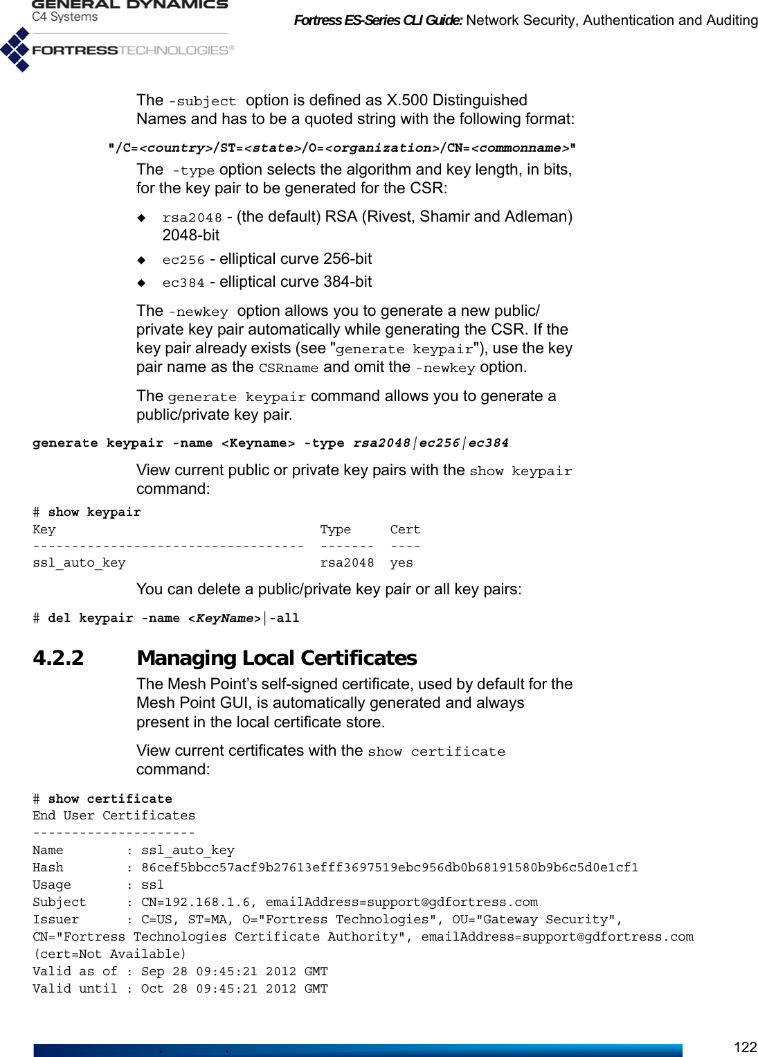
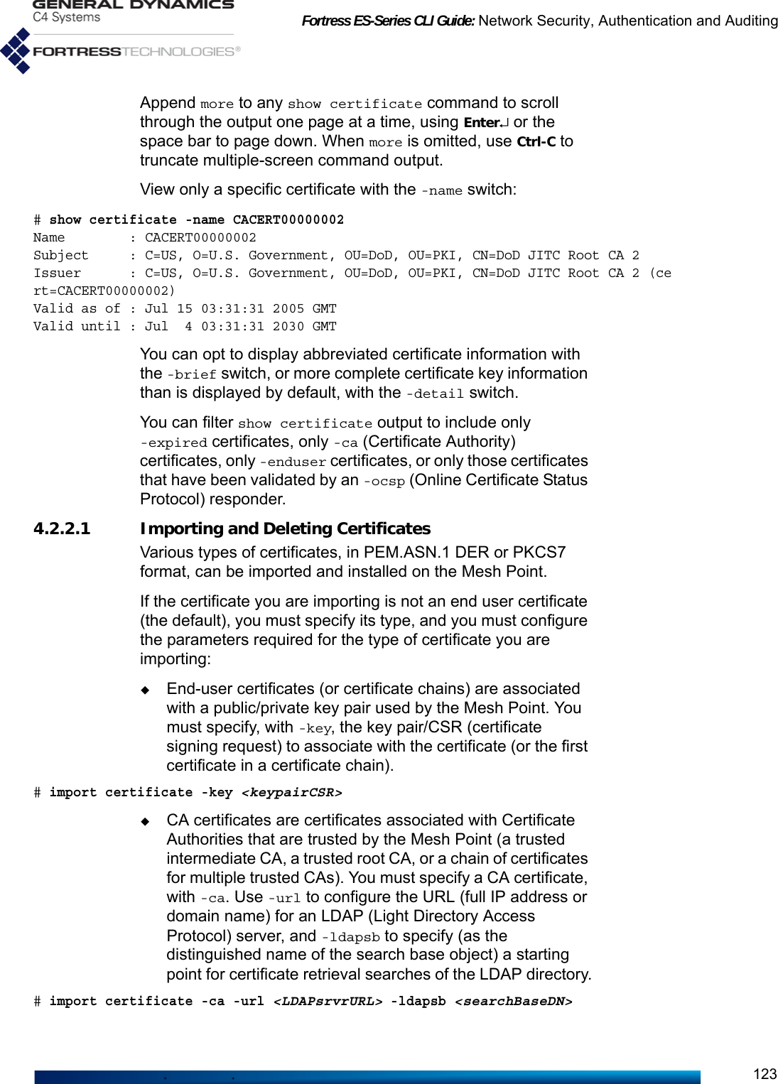
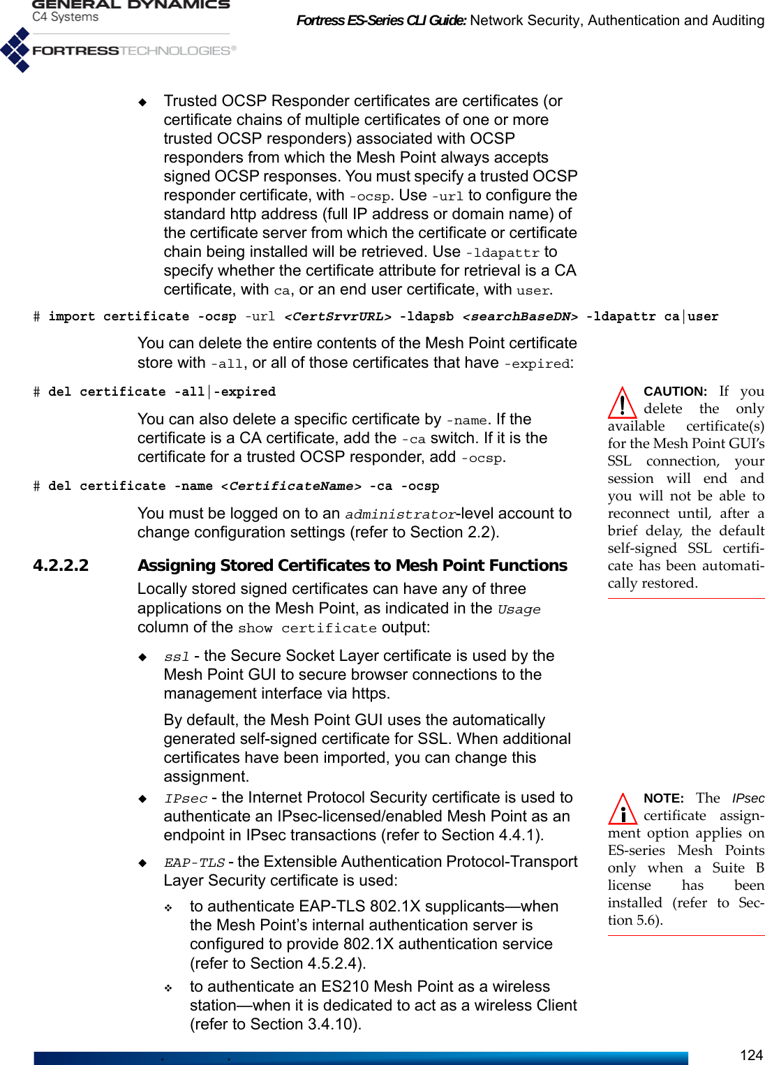
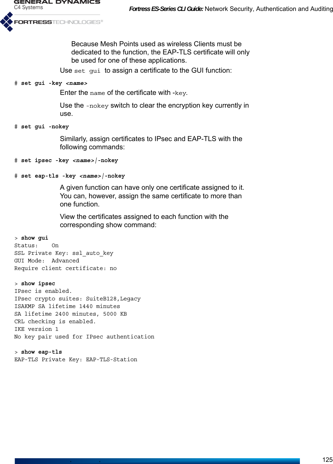
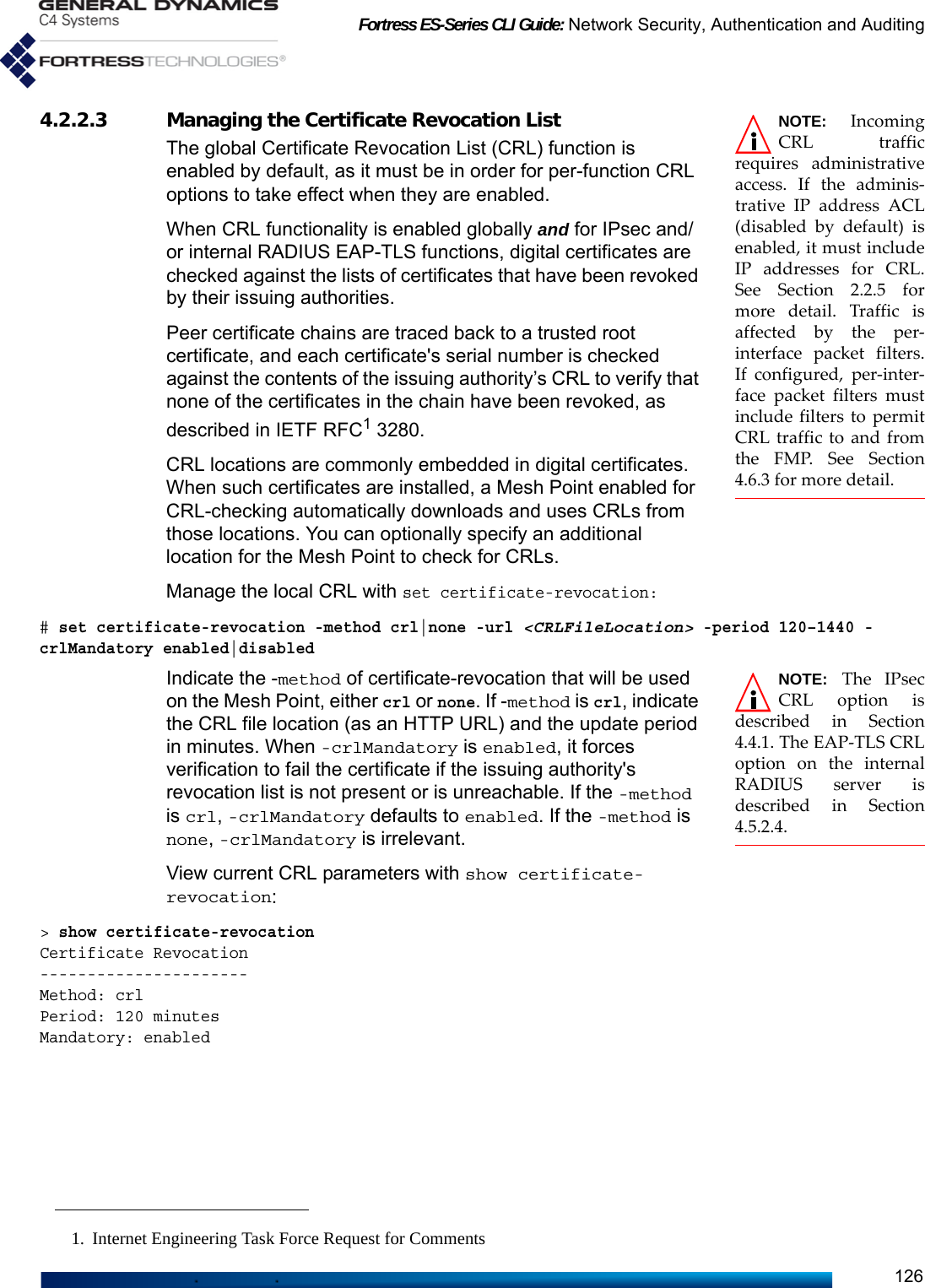
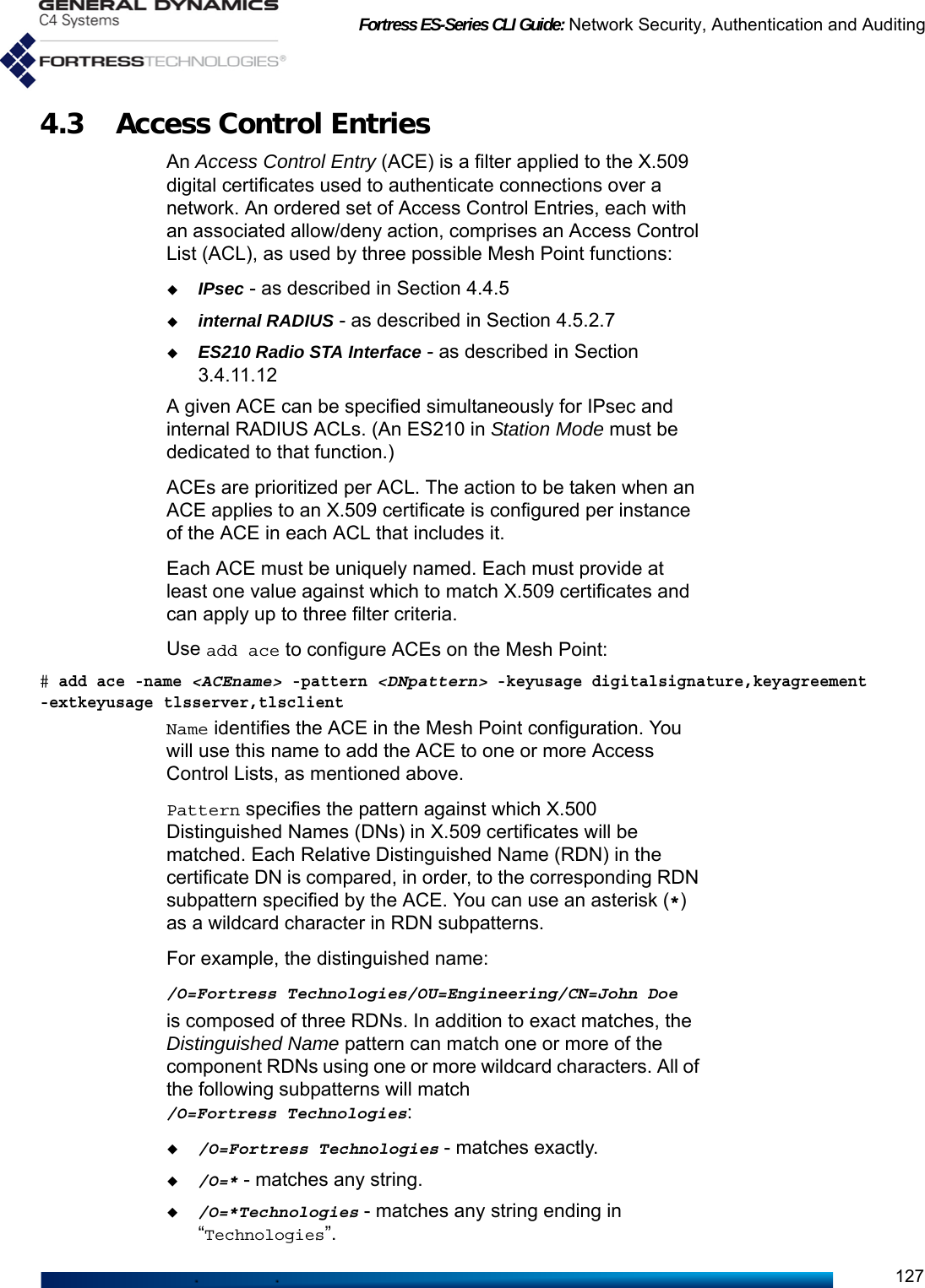
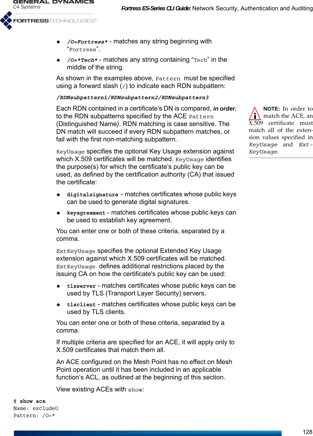
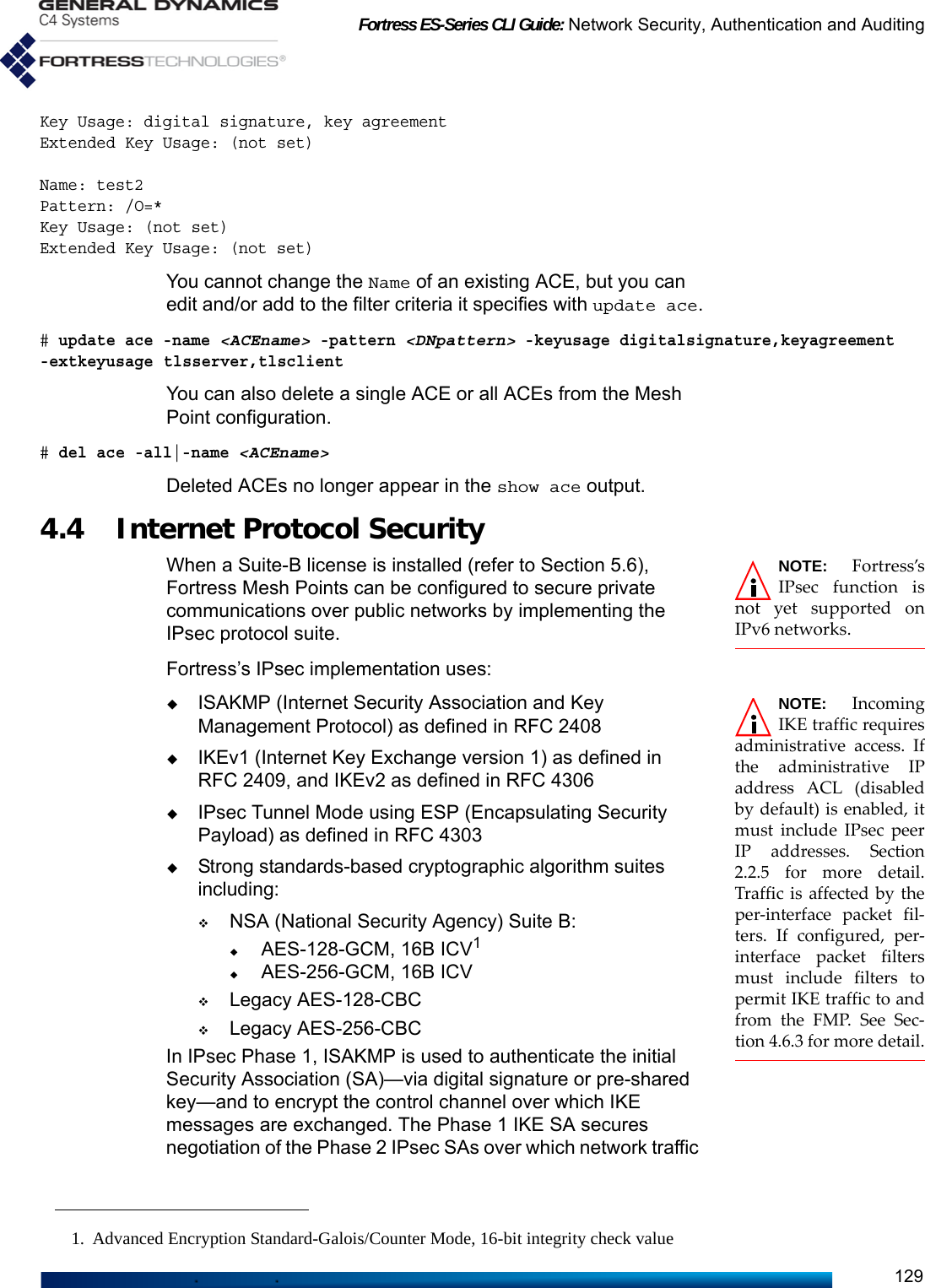
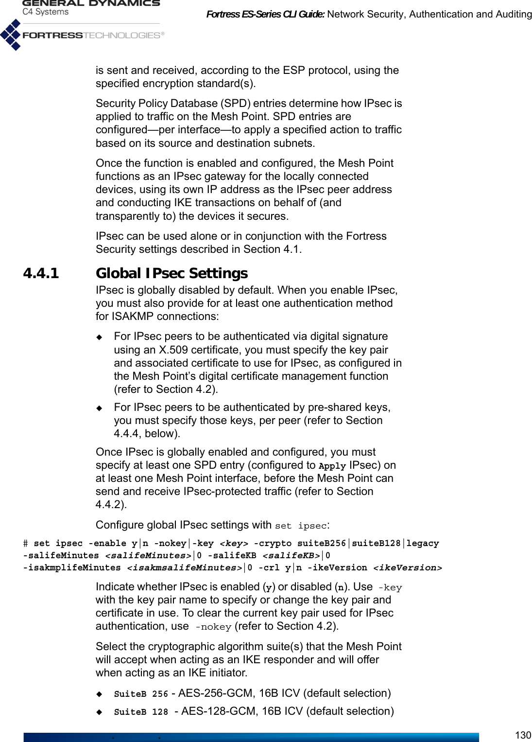
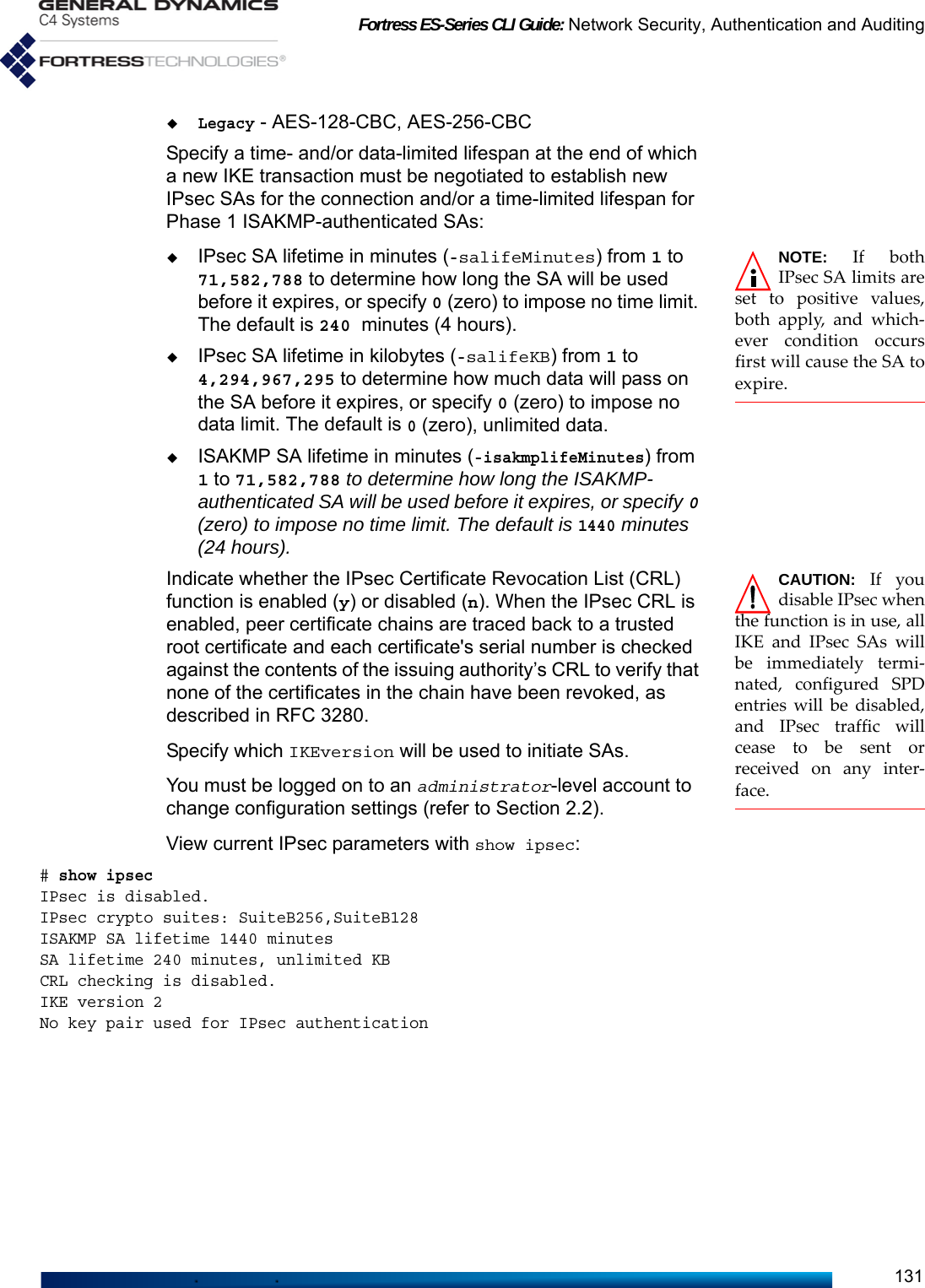
![Fortress ES-Series CLI Guide: Network Security, Authentication and Auditing1324.4.2 Interface Security Policy Database Entries CAUTION: WhenL2TP is enabled(Section 4.4.6), do notapply an SPD entry to awireless bridgingenabled BSS (Ena-bleWds[Y]). L2TP/IPsecis not supported forbridging BSSs.When IPsec is globally enabled and configured (refer to Section 4.4.1), the Mesh Point configuration can include up to 100 SPD entries, each associated with one of the Mesh Point’s network interfaces.An interface with at least one SPD configured for it is enabled to process IPsec traffic. An interface with no SPD configured for it is disabled for IPsec traffic.Each SPD entry defines the traffic to which it will apply by a specified local subnet of IP addresses—the source of outbound traffic and destination of inbound traffic. You can likewise specify a remote subnet of IP addresses to which an SPD will apply—defining traffic by its outbound destination/inbound source—as well as the IP address of the connecting device. How traffic defined by an SPD entry will be handled is determined by the specified Action, as shown in Table 4.1.Traffic on an interface that has no matching SPD definition will be handled according to whether any SPD entry has been configured for that interface:NOTE: Devicesthat implementthe IPsec model aresometimes referred to asred/black boxes.An interface with no SPD entry configured for it permits packets to pass unprotected by IPsec. Such an interface is a red interface, in IPsec terms, indicating the unprotected status of traffic on that interface.An interface with at least one SPD entry configured for it drops any packet that does not match (one of) the traffic selector(s) defined by the SPD entry(-ies) configured for that interface. In IPsec terms, such an interface is functioning as a black interface, indicating the secure status of any traffic passing on it.NOTE: Creating ordeleting an SPDentry causes all activeIPsec SAs to be renego-tiated. Add an SPD entry with add spd:# add spdName (policy name): From172NetTo520Interface (Interface name): encLocal address (Local address): 172.0.0.0Local mask (Local mask): 255.0.0.0Remote address (Remote address): 172.28.128.202Remote mask (Remote mask): 255.255.255.255Peer address (IPsec peer address): 172.28.120.121Table 4.1 Configurable SPD Entry Actionsaction inbound packets outbound packetsApplymust be IPsec-protected IPsec-encrypt and send as ESPBypassmust not be IPsec-protected send unprotected by IPsecDropdrop without further processing](https://usermanual.wiki/General-Dynamics-Mission-Systems/ES520P/User-Guide-2811717-Page-146.png)
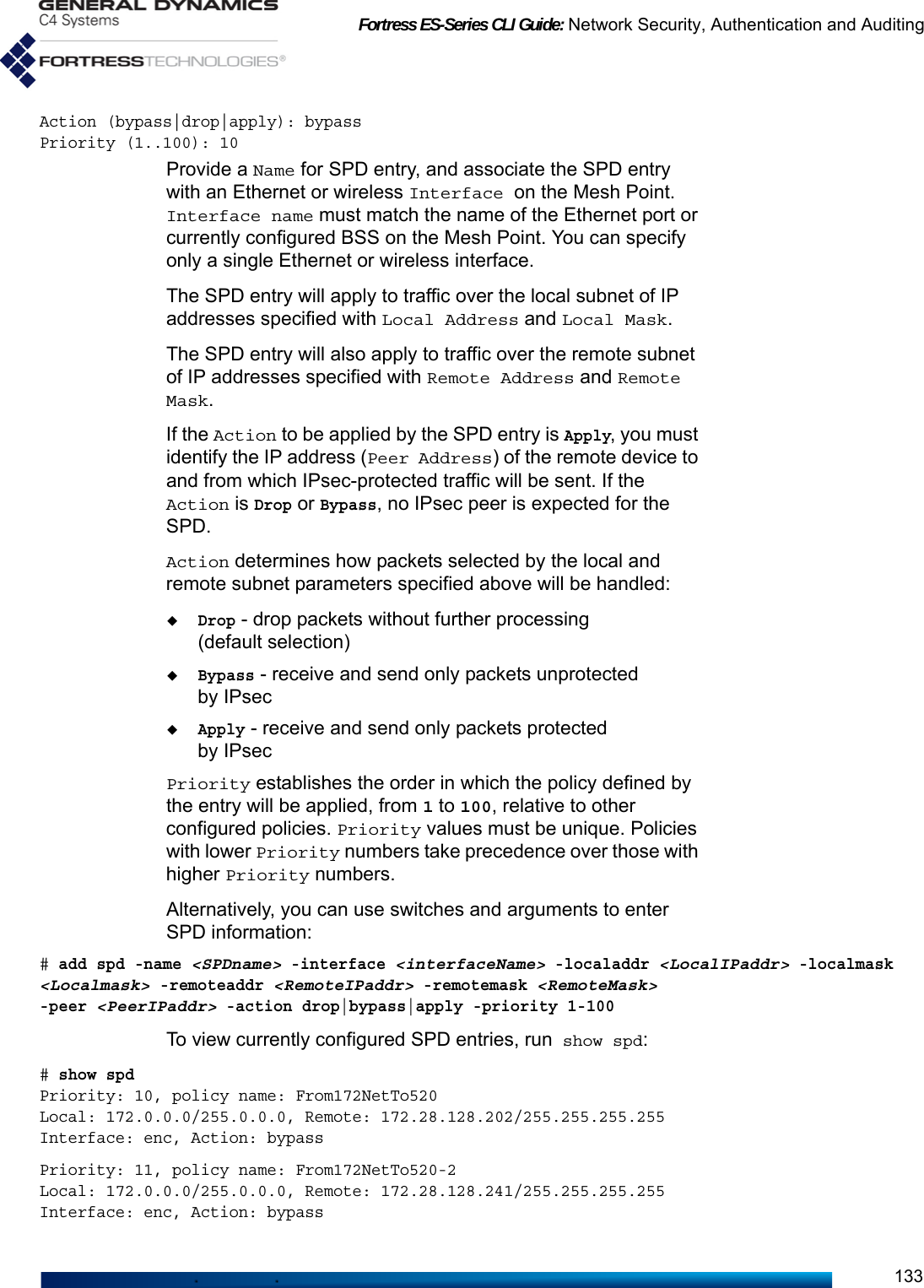
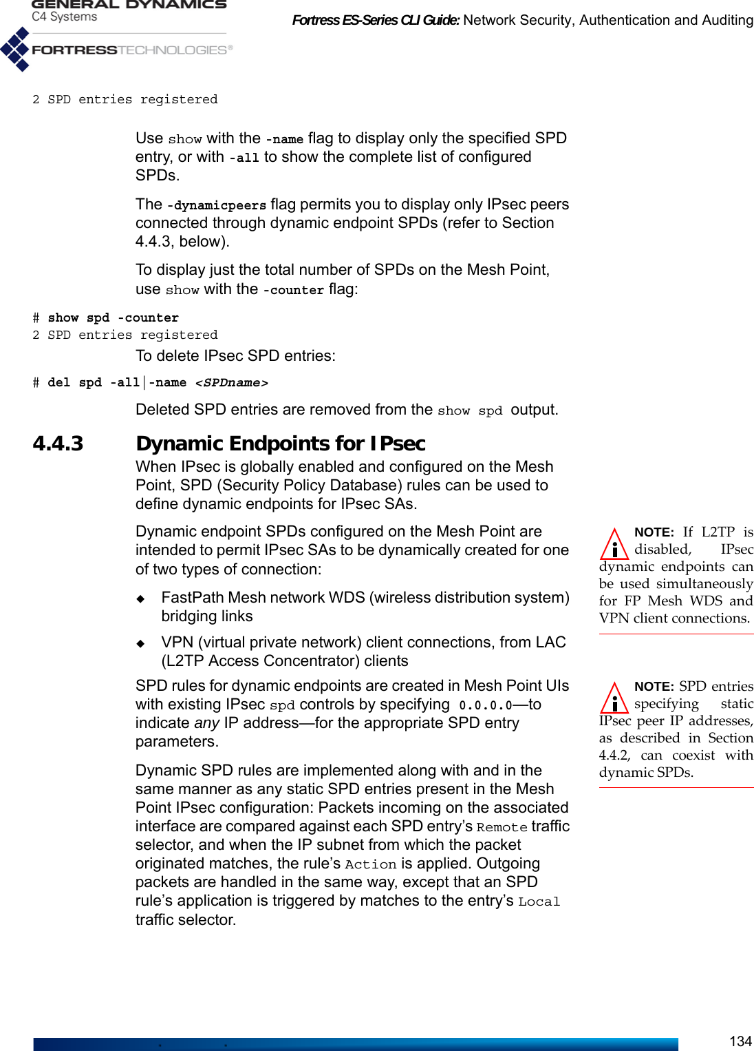
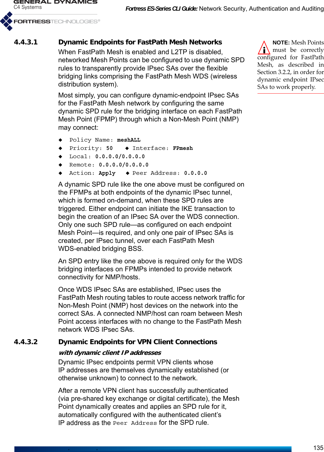
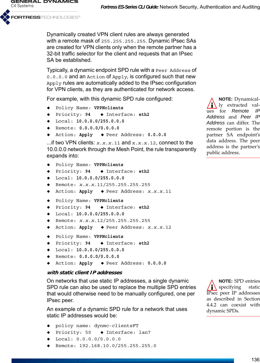
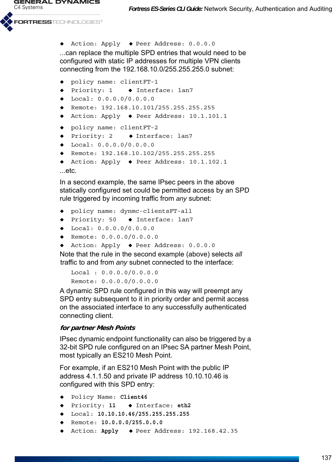
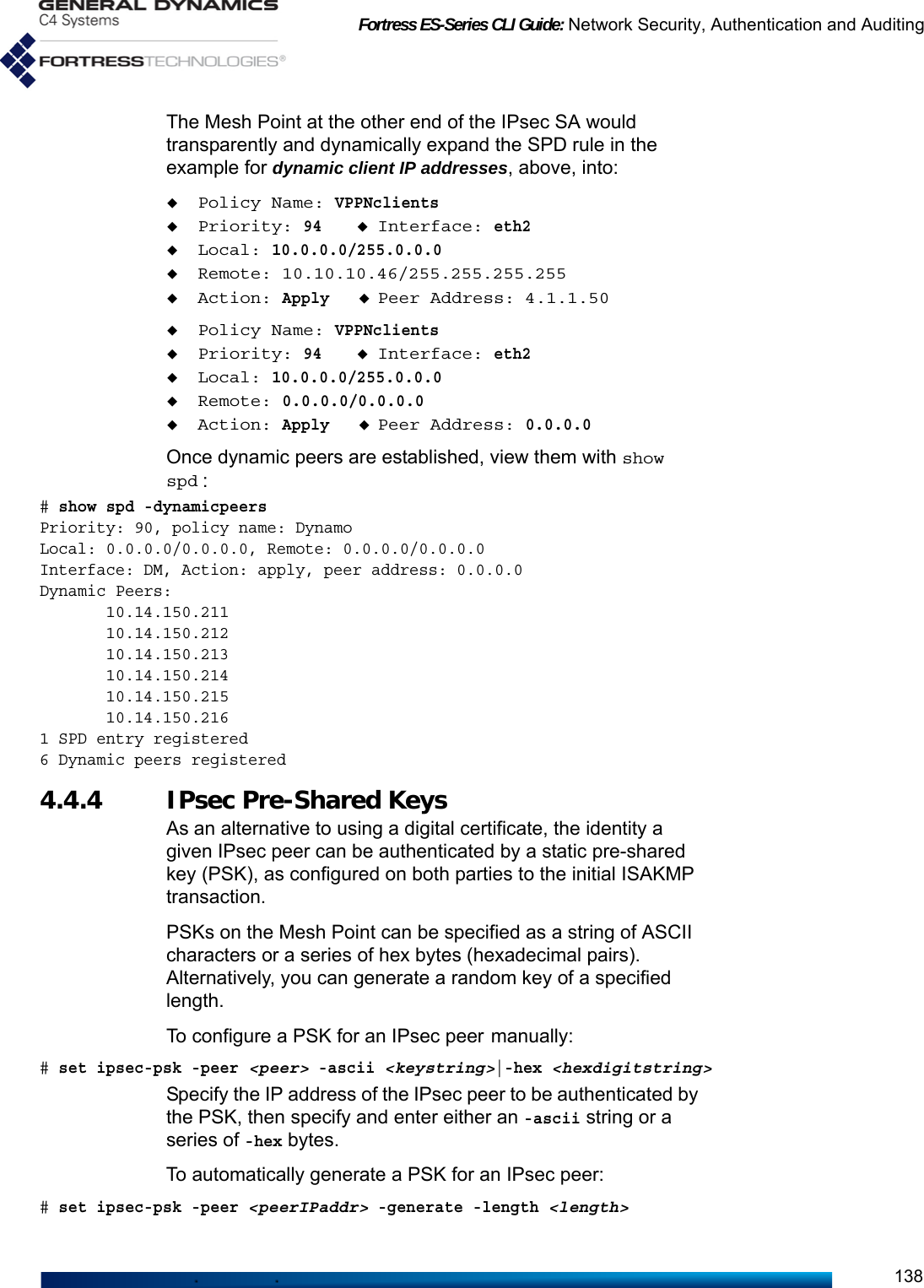
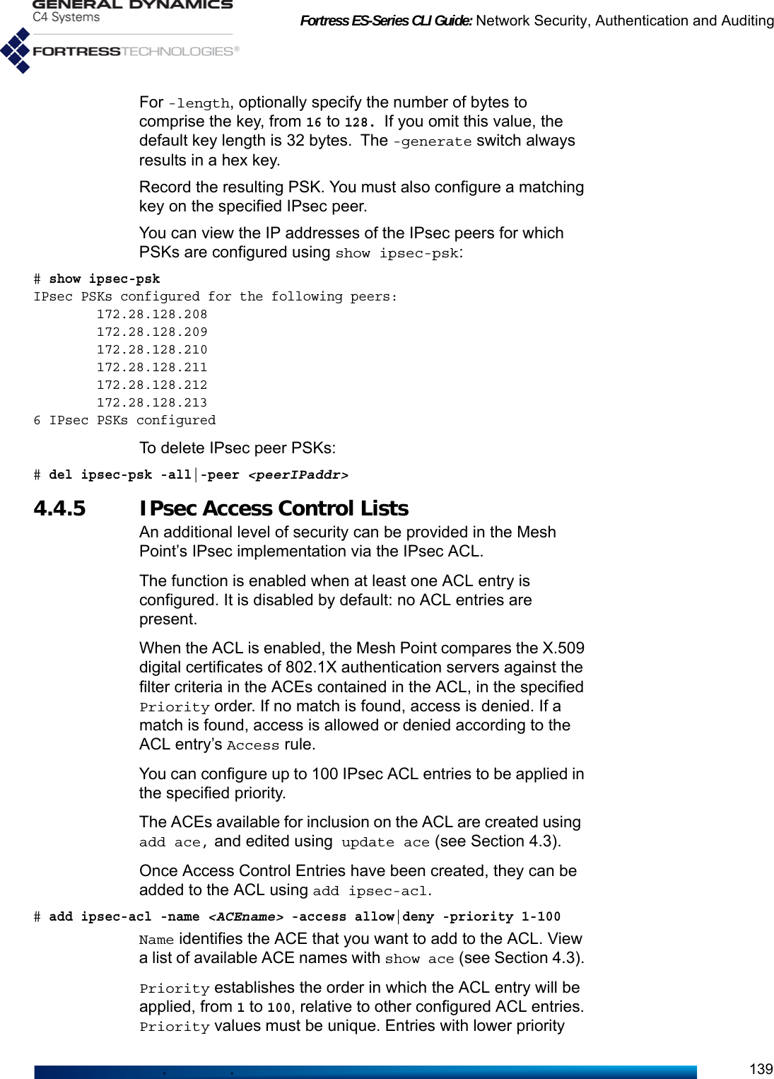
![Fortress ES-Series CLI Guide: Network Security, Authentication and Auditing140numbers take precedence over those with higher priority numbers.Access determines whether the Mesh Point will Allow (the default) or Deny access to an authentication server whose X.509 certificate matches the criteria specified in the ACL entry.View the entries in the ACL using show:# show ipsec -aclPrio Access ACE Name ---- ------ -------------------- 1 allow Test4 5 allow Test2 50 allow Test1 99 allow Test3 4 IPsec ACLs configuredUse the -counter switch to show the number of IPsec ACLs configured. To delete IPsec ACL entries:NOTE: Deleting allACL entries dis-ables the Mesh Point’sIPsec ACL function.# del ipsec-acl -all|-name <ACEname>Deleted ACL entries no longer appear when you run show ipsec -acl. 4.4.6 L2TP/IPsec ConnectionsNOTE: IncomingL2TP trafficrequires administrativeaccess. If the adminis-trative IP address ACL(disabled by default) isenabled, it must includeL2TP peer IP addresses.See Section 2.2.5 formore detail. Traffic isaffected by the per-interface packet filters.If configured, per-inter-face packet filters mustinclude filters to permitL2TP traffic to and fromthe FMP. See Section4.6.3 for more detail.When a Suite-B license is installed and IPsec is enabled, Layer 2 Tunnel Protocol (L2TP) functionality can be used to establish an L2TP/IPsec tunnel from a client (L2TP Access Concentrator, or LAC) to a server (L2TP Network Server, or LNS). L2TP can be used to establish a virtual network, which enables a remote host or other remote network to access an enterprise network securely. Based on a request from a remote device (LAC), an IPsec SA will be established, the remote user will be authenticated, and the L2TP tunnel session established. The tunnel session will remain active until it is deleted by an administrator, or the IPsec SA is deleted or expires. Currently the ES210 Mesh Point can only serve as an L2TP LAC, and the ES2440, ES820, and ES520 Mesh Points can only operate in LNS mode. A given device can operate in either LAC or LNS mode, but not both.Mesh Points do not support L2TP/IPsec on radio BSS interfaces enabled for wireless bridging (EnableWds[Y], described in Section 3.4.2). When L2TP is enabled, do not apply an SPD entry (as described in Section 4.4.2, below) to a wireless bridging interface.The L2TP LNS uses the configured RADIUS server(s) on a system, on which EAP-TLS must be enabled.](https://usermanual.wiki/General-Dynamics-Mission-Systems/ES520P/User-Guide-2811717-Page-154.png)
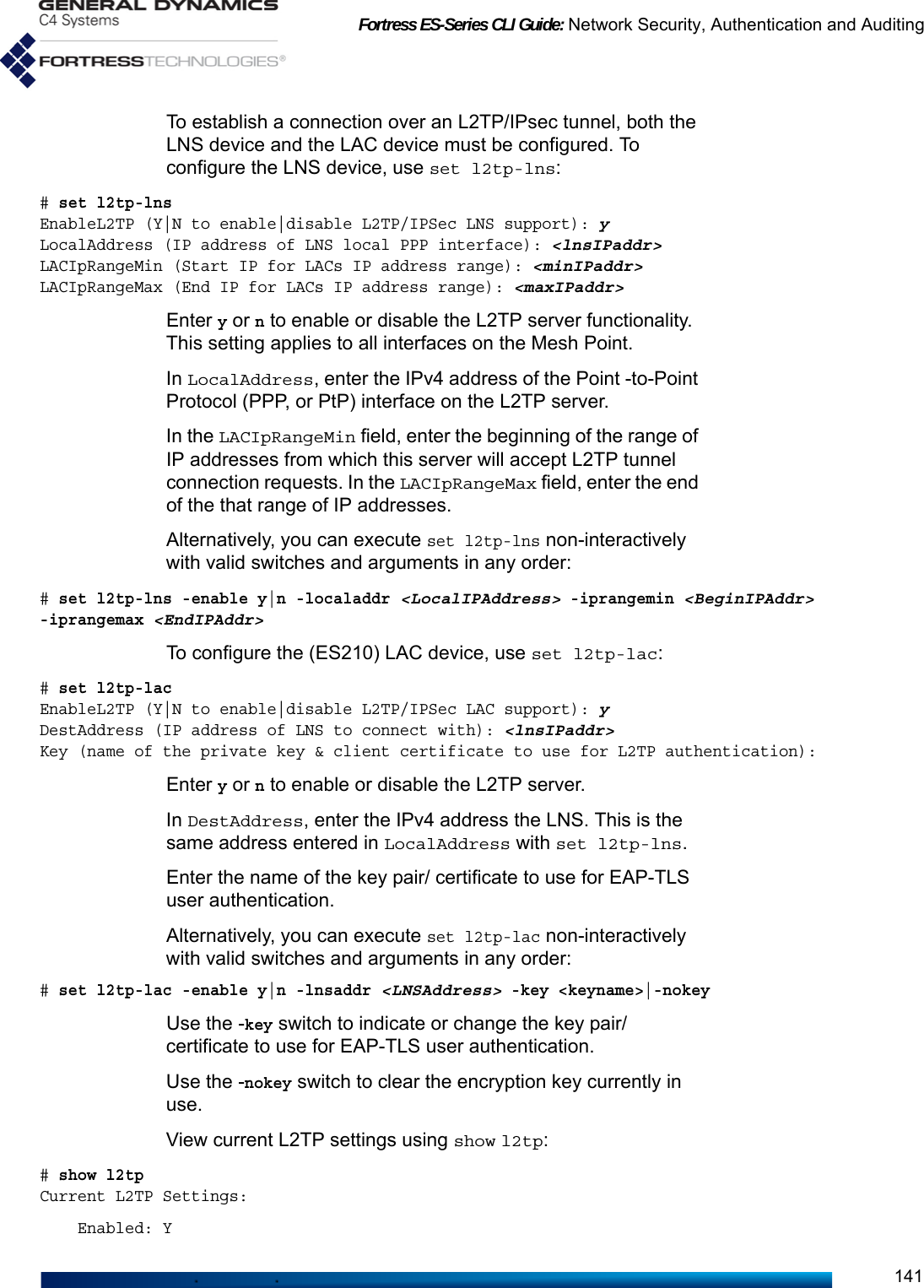
![Fortress ES-Series CLI Guide: Network Security, Authentication and Auditing142 Mode: lac LAC Setting: LNS connect address: 0.0.0.0 User auth key/cert: Not setUse the -sessions switch to view any active L2TP sessions, including Tunnel ID and Session ID:# show l2tp -sessionsCurrent L2TP Settings: Enabled: Y Mode: lns LNS Setting: Local address: 192.168.1.1 LAC IP range min: 192.168.1.2 LAC IP range max: 192.168.2.254 User auth key/cert: l2tpTunnel and session information:Tunnel Id Peer IP Our IP State Session Id15144 172.26.58.140 172.26.58.134 ESTABLISHED 59324You can delete all L2TP sessions, only those for a particular Tunnel ID, or a single session, using del l2tp-session. # del l2tp-session -all|-tunnelid <tunnelId>|-sessionid <sessionId>You must be logged on to an administrator-level account (refer to Section 2.2) to change configuration settings. 4.5 Authentication and Timeouts The Mesh Point is equipped with an internal authentication service (Section 4.5.2) and can be configured to use an external Fortress RADIUS server (internal to another Mesh Point) or a 3rd-party freeRADIUS or Microsoft® IAS® (Internet Authentication Service) server, as described below.Timeouts can be configured for Mesh Points that are not using RADIUS (Section 4.5.5) and in the internal RADIUS server (Section 4.5.2 and Section 4.5.3).4.5.1 Authentication Servers Use show auth to display currently configured authentication servers:> show auth[Authentication Server List]Name Priority Mode Type AuthType IPaddr PortNumber Description AdminState------ -------- -------- ---------- ----------------- ------------ ---------- ----------- ----------RADIUS 1 external thirdParty USER_DEVICE|8021X 192.168.1.22 1812 active[Highest Priority Active Authentication Server Entry For Each Type]AuthType IpAddr AdminState Type----------- ------------ ---------- ----------](https://usermanual.wiki/General-Dynamics-Mission-Systems/ES520P/User-Guide-2811717-Page-156.png)
![Fortress ES-Series CLI Guide: Network Security, Authentication and Auditing1438021X 192.168.1.22 active thirdPartyADMIN 0.0.0.0 inactiveUSER_DEVICE 192.168.1.22 active thirdPartyNo authentication servers are configured by default.The Mesh Point can actively use up to three authentication servers at a time. You can configure the same authentication server to provide more than one supported authentication type. Only the active server for the applicable authentication type will determine the success or failure of a given authentication attempt. Failed credentials are not forwarded to any other server.NOTE: Only fortressRadiusservers support all threetypes of authentication(see the Fortress MeshPoint Software GUI Guidefor more detail). For redundancy, multiple authentication servers can be configured on the Mesh Point. The additional servers will become active only if the server with the earliest priority number for a given authentication type becomes unavailable. In this case the server next in the priority sequence for that authentication type, if one is configured and available, will be used.Add an external authentication server to the Mesh Point configuration interactively with add auth:# add authName (Name of the server): radSrv1Type (fortressRadius|thirdParty): fortressRadiusAuthType (userdev|8021x|admin): userdevPriority (Priority [0..999] of the server): 4Sharedkey (Authentication Key [1-31 characters in length]): sharedkey4IPaddr (IP address of the external server): 192.168.1.9PortNumber (Port number [1..65535] to communicate with the server): 1812MaxRetries (Maximum number of retries (userdev and admin auth types only)): 3AdminState (active|inactive to set admin state (default is active)):Description (Description of the server):You must name the server (Name), identify its Type, and specify what type of authentication the server will perform (AuthType). You can also specify the Priority number, from 1–999, at which the server will be used for the specified authentication type. Lower priority numbers are used first. A value of 0 (zero) assigns a priority of last. By default, servers are assigned consecutive priority numbers, beginning with 1, in the order in which they are added to the Mesh Point’s configuration.You should then specify the external server’s IPaddress and SharedKey (1–64 printable characters), and the PortNumber to use for authentication transactions with the server.In addition, you can specify how many times the Mesh Point will attempt to connect to the server before determining that the server is unavailable and going on to the next configured](https://usermanual.wiki/General-Dynamics-Mission-Systems/ES520P/User-Guide-2811717-Page-157.png)
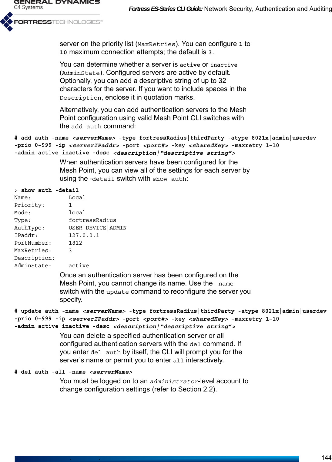
![Fortress ES-Series CLI Guide: Network Security, Authentication and Auditing1454.5.2 Internal Authentication ServerNOTE: IncomingRADIUS trafficrequires administrativeaccess. If the adminis-trative IP address ACL(disabled by default) isenabled, it must includeIP addresses of authen-ticating users, devices,administrators and802.1X supplicants. SeeSection 2.2.5 for moredetail. Traffic is affectedby the per-interfacepacket filters. If config-ured, per-interfacepacket filters mustinclude filters to permitRADIUS traffic to andfrom the FMP. See Sec-tion 4.6.3 for moredetail.The users and Secure Client devices you add to the Mesh Point’s local authentication configuration apply only when the internal authentication, or RADIUS, server is enabled (below).View current settings for the internal authentication server with show localauth:> show localauthEnableLocalAuth: NPort: 1812EnableDevAuth: NEnableUserAuth: YDefaultDeviceState: pendingDefaultMaxRetries: 3DefaultIdleTimeout: 30DefaultSessionTimeout: 30EnableAdminAuth: NEnable8021xAuth: NProtocols: md5Check CRL: NEnableOcsp: NOcspUrl:EnableOcspNonce: YCaCertUrl:LdapSearchBase:EAP-TLS cipher set: allPriority: 0The above output shows the default settings for the internal authentication server, which is disabled by default. The internal authentication server is enabled and configured with set localauth:# set localauthEnableLocalAuth[N] (Y|N to enable|disable local authentication server): yPort[1812] (Port number to communicate):SharedKey (Authentication key): authkeyPriority (Local server priority [0..999]):EnableDevAuth[N] (Y|N to enable|disable Device authentication): yEnableUserAuth[N] (Y|N to enable|disable User Authentication): yDefaultDeviceState[pending] (pending|allow|deny): allowDefaultMaxRetries[3] (Maximum attempts at reaching server before failover 1-30, default is 3):DefaultIdleTimeout[30] (User idle timeout in minutes 1-720, default is 30):DefaultSessionTimeout (Authentication timeout in minutes, 1-200, default is 30):EnableAdminAuth[N] (Y|N to enable|disable administrator authentication):Enable8021xAuth[N] (Y|N to enable|disable 802.1x authentication):EnableEAP-MD5 (Y|N to enable|disable support for EAP-MD5 protocol):EnableEAP-TLS (Y|N to enable|disable support for EAP-TLS protocol):EnableCRLCheck[N] (Y|N to enable|disable CRL check):EnableOcsp[N] (Y|N to enable|disable OCSP):OcspUrl[""] (URL of OCSP responder):EnableOcspNonce[Y] (Y|N to enable|disable OCSP nonce):CaCertUrl[""] (URL of CA certificate or chain):LdapSB[""] (Search base for CA certificate or chain (LDAP only)):](https://usermanual.wiki/General-Dynamics-Mission-Systems/ES520P/User-Guide-2811717-Page-159.png)
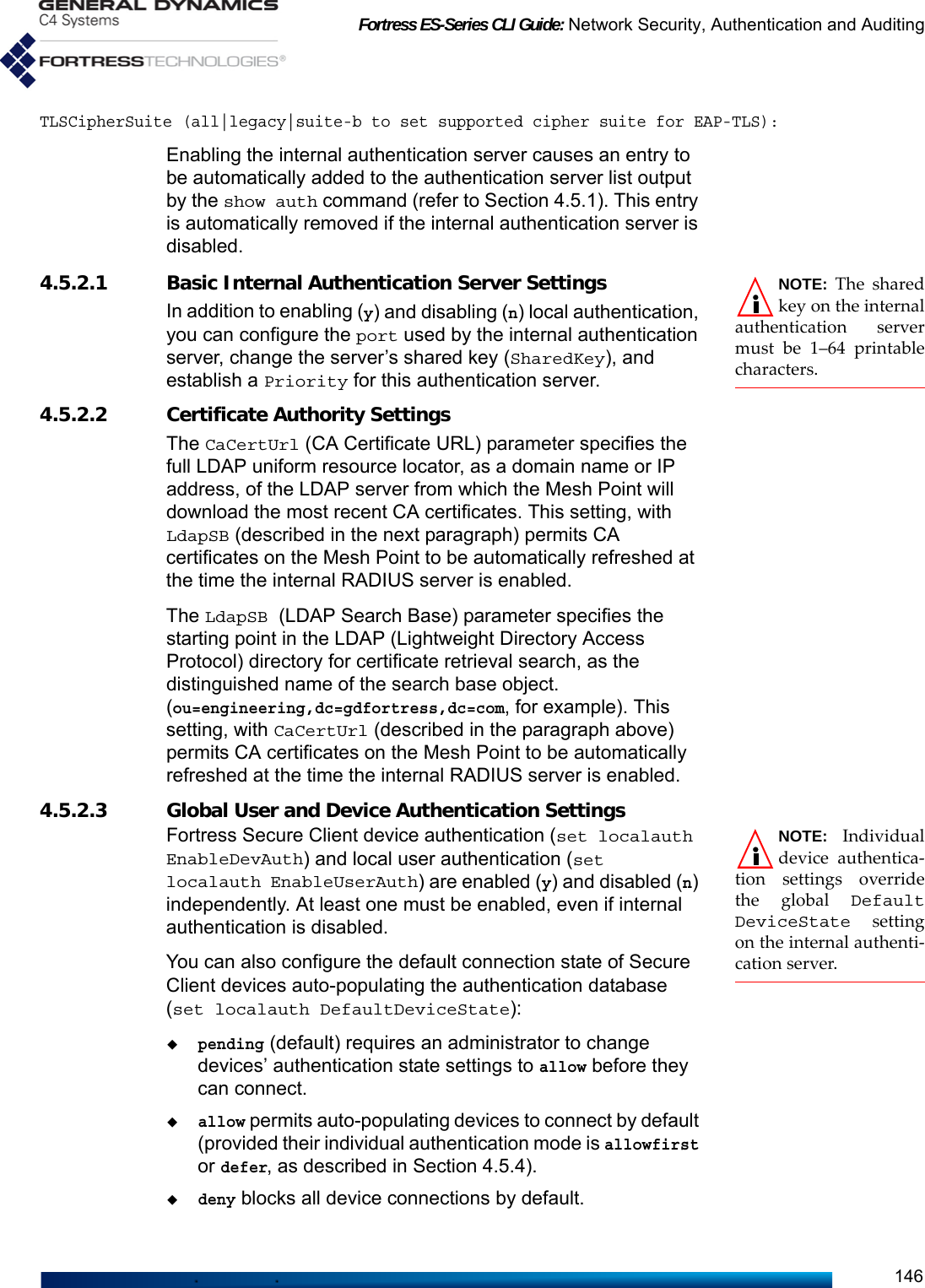
![Fortress ES-Series CLI Guide: Network Security, Authentication and Auditing147The maximum number of authentication retries (DefaultMaxRetries) and idle and session timeout settings (DefaultIdleTimeout and DefaultSessionTimeout) configured on the internal authentication server are applied globally to all authenticating devices and users. A device that exceeds the maximum allowable retry attempts to authenticate on the Mesh Point is locked out until the device’s individual authentication mode is set to allowfirst Such a device is locked out on every Mesh Point in a network, and you must change the device’s authentication mode on every Mesh Point that handles traffic from the device.Users who exceed the maximum allowable retry attempts to log on to the Fortress-secured network are locked out until you reset their sessions. On a network of Mesh Points, you must reset the session on each Mesh Point that passes traffic for the device.Specify maximum authentication retries in whole numbers between 1 and 255; the default is 3. Specify idle and session timeouts in minutes: between 1 and 720 for idle timeouts, and 1 and 200; for session timeouts. 0 (zero) disables the timeout setting. The default session timeout is 30 minutes. The default idle timeout is 30 minutes.4.5.2.4 Local 802.1X Authentication SettingsThe Mesh Point’s internal RADIUS server can be configured to authenticate 802.1X supplicant credentials using two possible EAP (Extensible Authentication Protocol) types.NOTE: EAP-TLSprovides a signifi-cantly higher level ofsecurity than EAP-MD5.EAP-MD5 verifies an MD5 (Message-Digest algorithm 5) hash of each user’s password, which requires a user’s credentials to be present in the Mesh Point’s local user authentication service before the local 802.1X service can authenticate that user. Refer to Section 4.5.3 for guidance.In order to use EAP-TLS (EAP with Transport Layer Security) public key cryptography authentication, you must import a valid EAP-TLS digital certificate for the local service and the root CA (Certificate Authority) certificate that signs the local server certificate. You must also import any root CA certificate(s) used to sign supplicant certificates, so that the local server can verify their authenticity. Refer to Section 4.2 for guidance. Additional local server configuration settings in set localauth apply only to EAP-TLS, as noted below. Enable8021xAuth[N] (Y|N to enable|disable 802.1x authentication):EnableEAP-MD5 (Y|N to enable|disable support for EAP-MD5 protocol):EnableEAP-TLS (Y|N to enable|disable support for EAP-TLS protocol):EnableCRLCheck[N] (Y|N to enable|disable CRL check):TLSCipher (all|legacy|suiteb to set supported cipher suite for EAP-TLS):](https://usermanual.wiki/General-Dynamics-Mission-Systems/ES520P/User-Guide-2811717-Page-161.png)
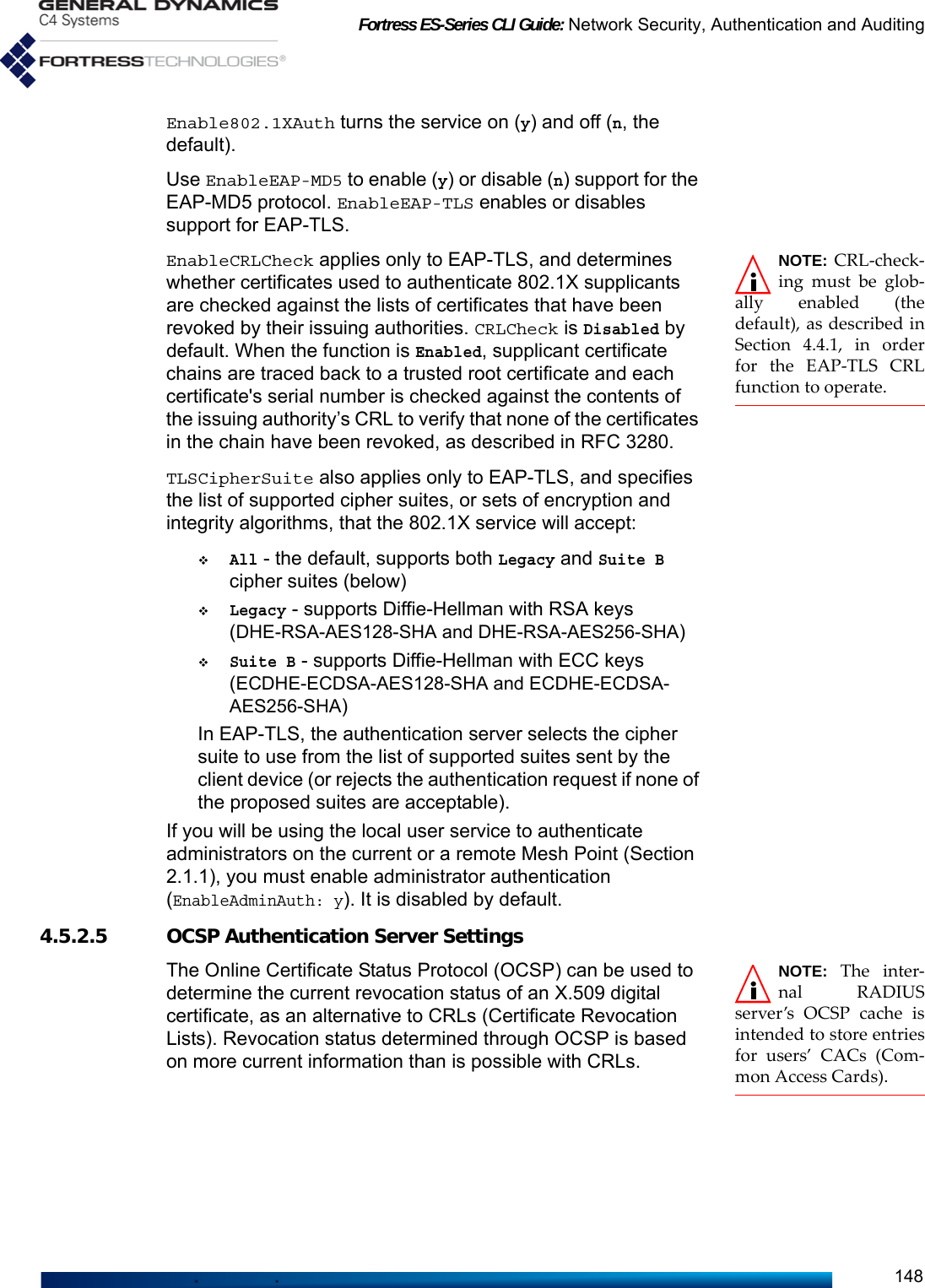
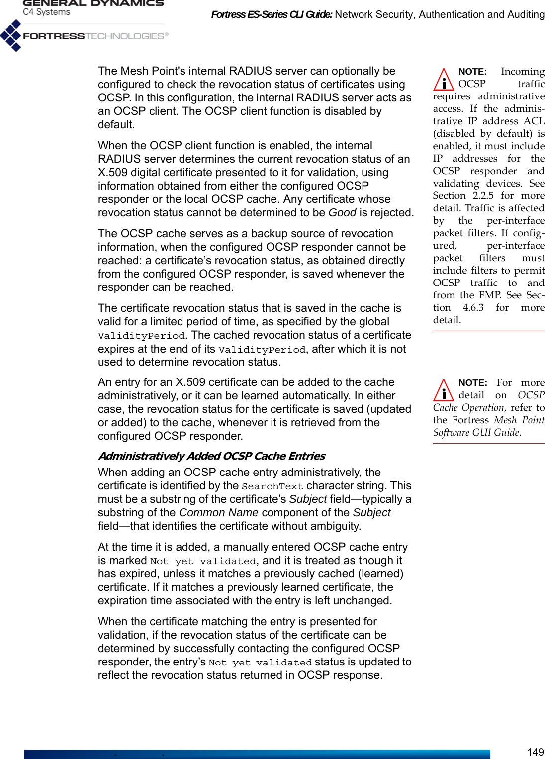
![Fortress ES-Series CLI Guide: Network Security, Authentication and Auditing150OCSP Cache LearningThe OCSP cache learning function (AutoLearningEnabled: Y) can be used to limit which certificates will be considered for validation, as follows: NOTE: Adminis-tratively addedOCSP cache entries per-mit the correspondingcertificate to be consid-ered for validation evenwhen the entry’s Statusis Not yet validated. When OCSP cache learning is enabled, every certificate presented to the internal authentication server for validation will be processed. If the revocation status of the certificate can be successfully determined by contacting the configured OCSP responder, an entry for the certificate will be added to the cache—or, if an entry already exists for the certificate, it will be updated or refreshed in the cache.When cache learning is disabled (AutoLearningEnabled: N), not all certificates presented to the internal authentication server for validation will be processed. Only certificates that match an entry already present in the cache will be considered for validation. Other certificates will be rejected without further processing.Three set localauth options configure the Mesh Point’s OCSP function globally:EnableOcsp[N] (Y|N to enable|disable OCSP):OcspUrl[""] (URL of OCSP responder):EnableOcspNonce[Y] (Y|N to enable|disable OCSP nonce):Turn the OCSP client function on (Y) and off (N, the default) with EnableOcsp. If you enable OCSP client functionality, you must configure the OCSP responder URL (OcspUrl). Specify the full global web address, as a domain name or IP address, of the server that will process the Mesh Point's OCSP requests. By default, OCSP requests from the internal authentication server contain the nonce extension (EnableOcspNonce: Y). Alternatively, the nonce extension can be omitted (EnableOcspNonce: N).4.5.2.6 OCSP Cache Settings and ManagementWhen OCSP is enabled, use show ocspcache to observe global OCSP cache settings and any cache entries:# show ocspcacheOCSP Cache (ValidityPeriod: 168 hours, AutoLearningEnabled: Y, TotalEntries: 0)Index Common Name Search Text Status------ ------------------- ------------------- -----------------No entries to showValidityPeriod specifies the length of time, in hours, for which OCSP cache entries are renewed, upon receipt of a validation status of Good from the configured OCSP responder, or when the entry is manually renewed. The default ValidityPeriod is 168 hours (seven days).](https://usermanual.wiki/General-Dynamics-Mission-Systems/ES520P/User-Guide-2811717-Page-164.png)
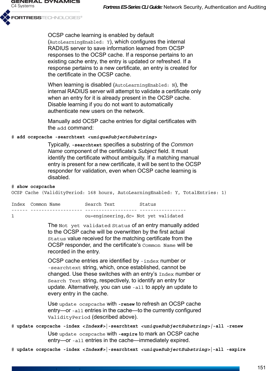
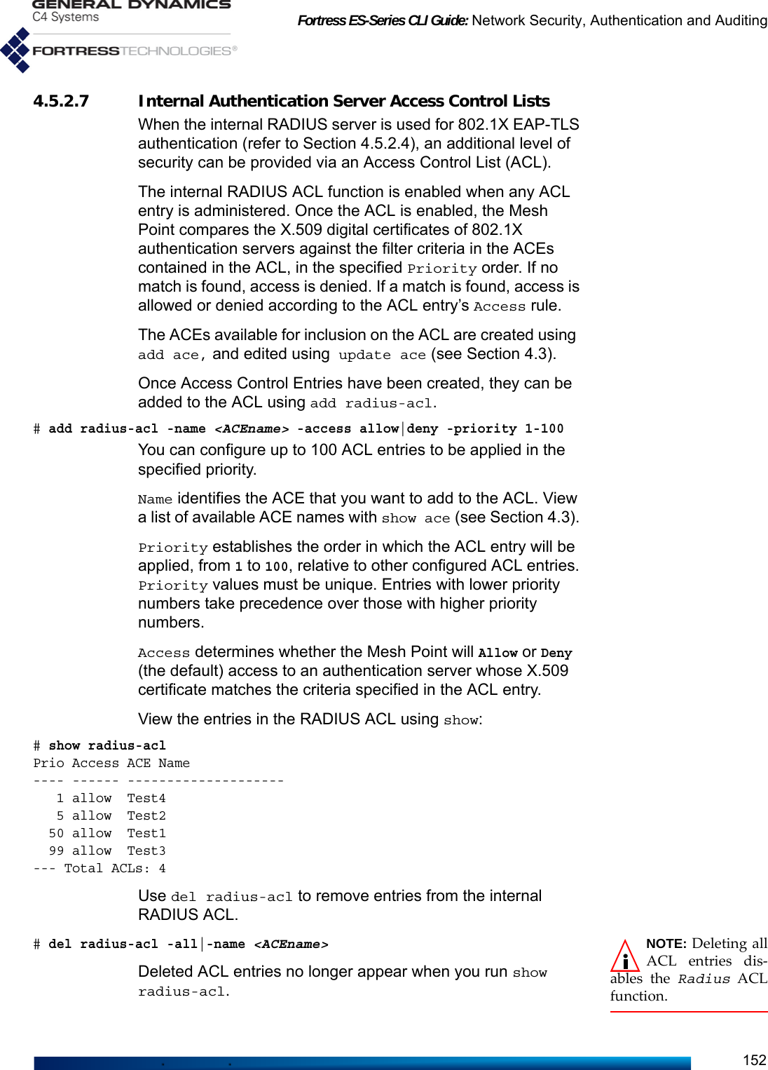
![Fortress ES-Series CLI Guide: Network Security, Authentication and Auditing153NOTE: The MeshPoint maintains aseparate, local adminis-trator database thatautomatically “learns”administrators who suc-cessfully logon througha Fortress user databaseor third-party RADIUSserver (refer to Section2.2.3).4.5.3 User Authentication Users for whom you create authentication accounts will be one of two types: Secure Client users connect to the Mesh Point’s encrypted interfaces via devices running the Fortress Secure Client; Admin users are using the Mesh Point’s local user authentication database to gain administrative access to the Mesh Point’s management interface.View currently configured users with show userauth:# show userauthUserName UserFullname IdleTimeout SessionTimeout AdminState AdminAuth-------- ------------ ----------- -------------- ---------- -------------admin2 30 200 active Administratorperson1 Full Name1 30 200 active None person2 Full Name2 30 200 active Noneperson3 Full Name3 30 200 active NoneAdd new users interactively with add userauth:# add userauthUserName (User name): <username>Password (User password): <userpw>Password Confirm (Password Confirm): <userpw>IdleTimeout[30] (User idle timeout in minutes): 1–720SessionTimeout[1200] (User session timeout in minutes): 1—200UserFullname (User full name): <“Full Username”>AdminState (active|inactive to set User's admin state): active|inactiveAdminAuth (logviewer|maintenance|administrator|none):none|administrator|maintenance|logviewerAlternatively, you can add users to the Mesh Point’s internal RADIUS server using valid Mesh Point CLI switches with the add command:# add userauth -name <username> -passwd <userpw> -passwordConfirm <userpw>-idletimeout 1–720 -sestimeout 1—200 -fullname <“Full Username”> -admin active|inactive-adminauth none|administrator|maintenance|logviewerNOTE: Passwordsdo not need to beunique.The username (-name) and password (-passwd) are the credentials the user must input in order to authenticate on the Mesh Point. Both are required. Usernames must be 1–32 (inclusive) alphanumeric characters in length. Passwords must comply with the requirements configured with set account (page 17). You can also enter a user’s full name with the -fullname switch, which accepts an entry up to 250 characters in length; enclose the string in quotation marks to include spaces.](https://usermanual.wiki/General-Dynamics-Mission-Systems/ES520P/User-Guide-2811717-Page-167.png)
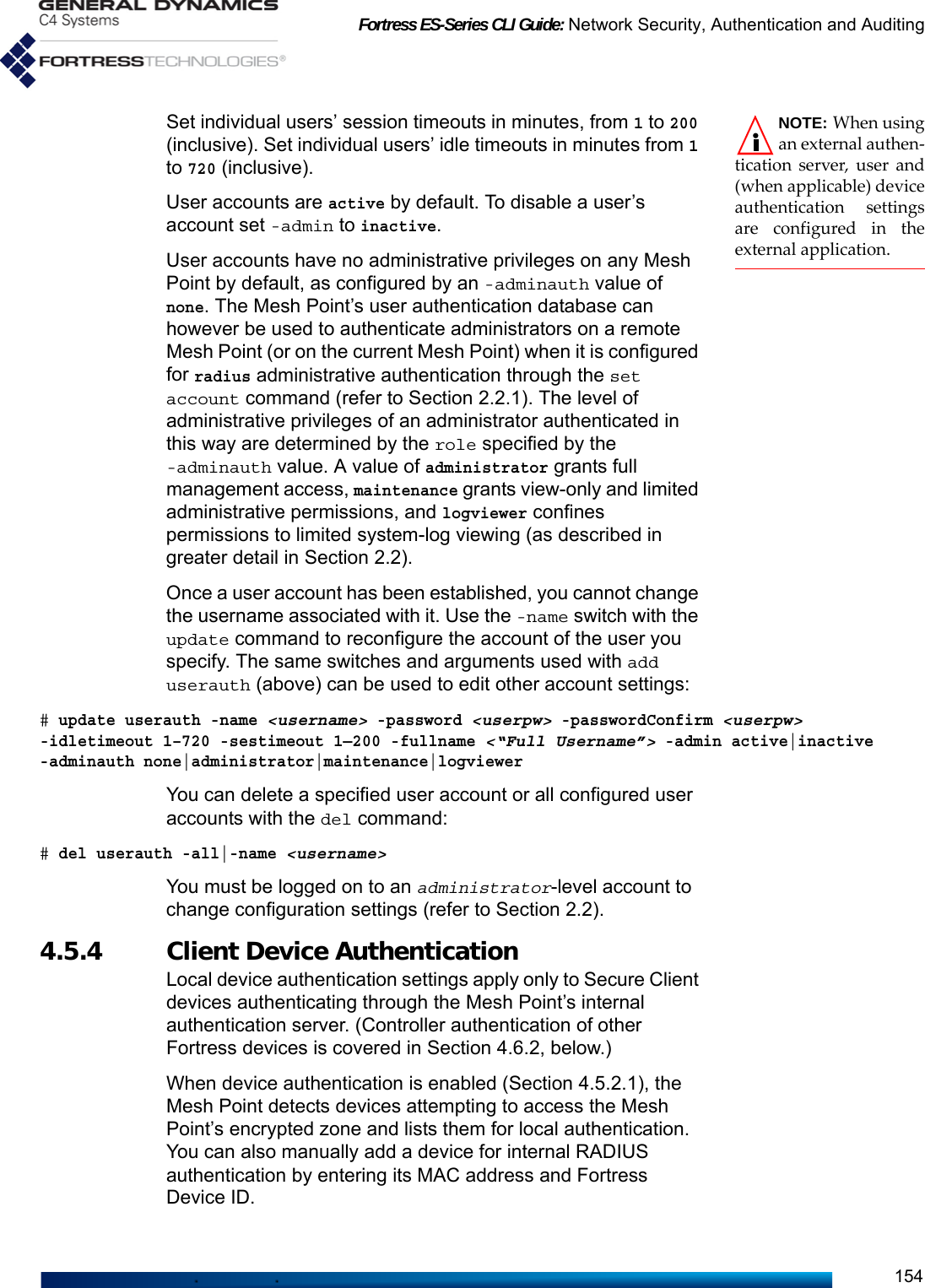
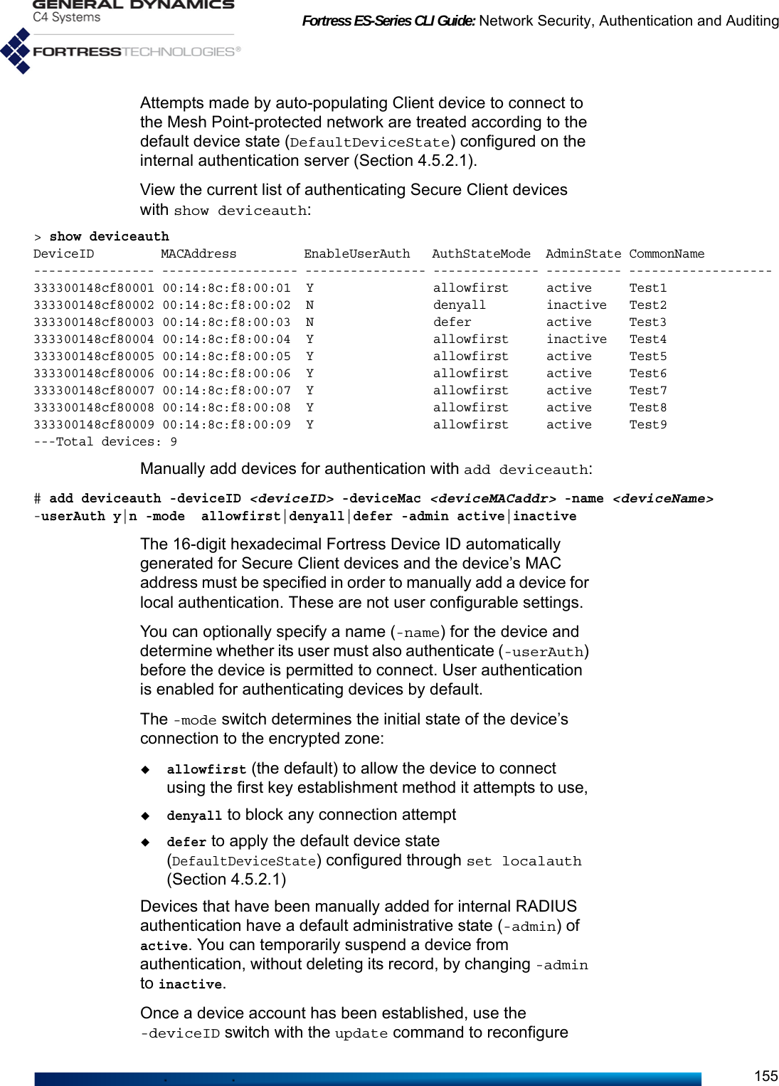
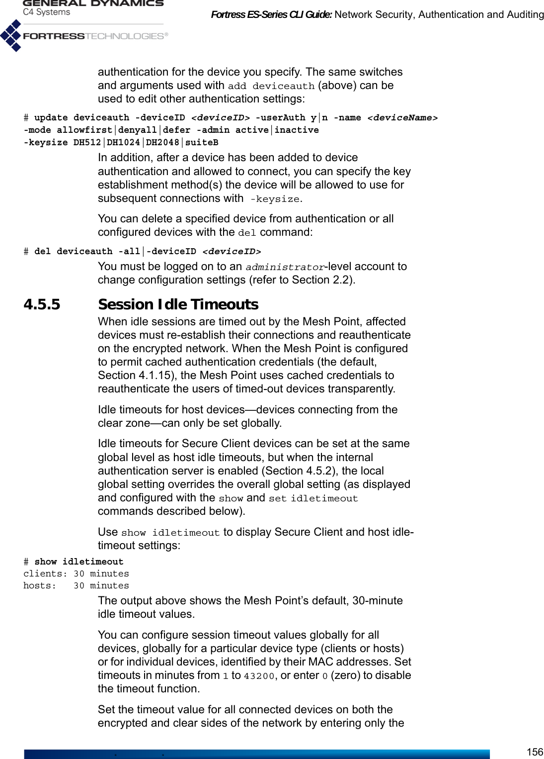
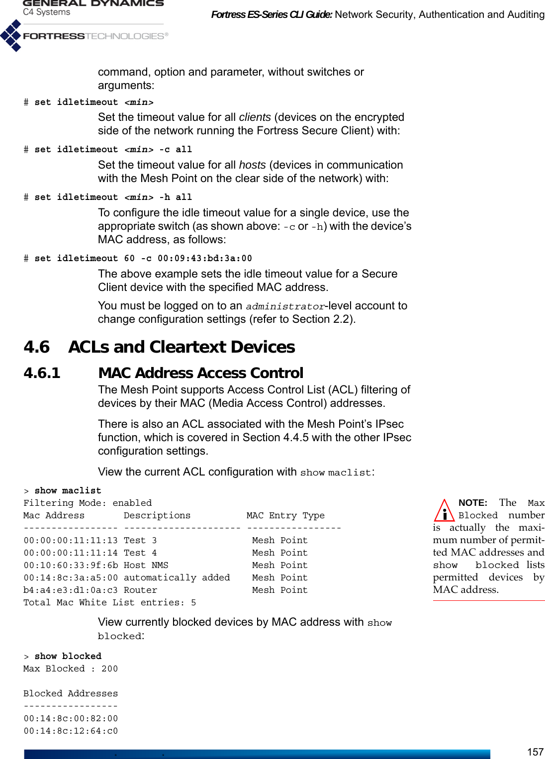
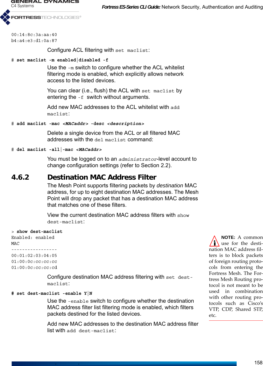
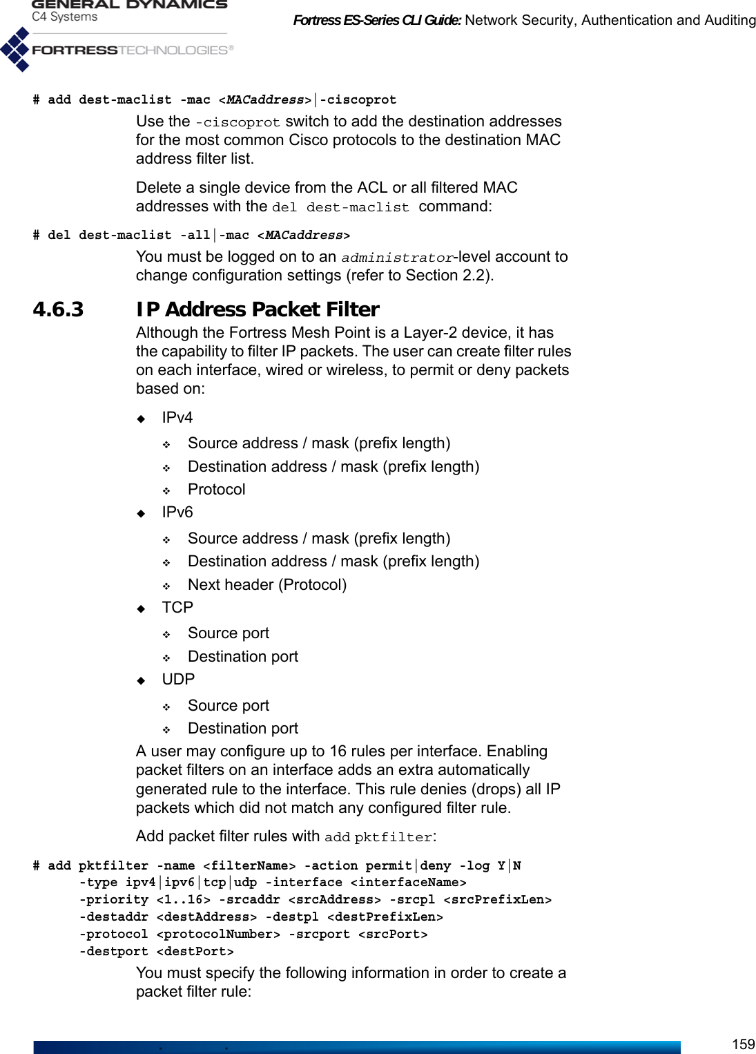
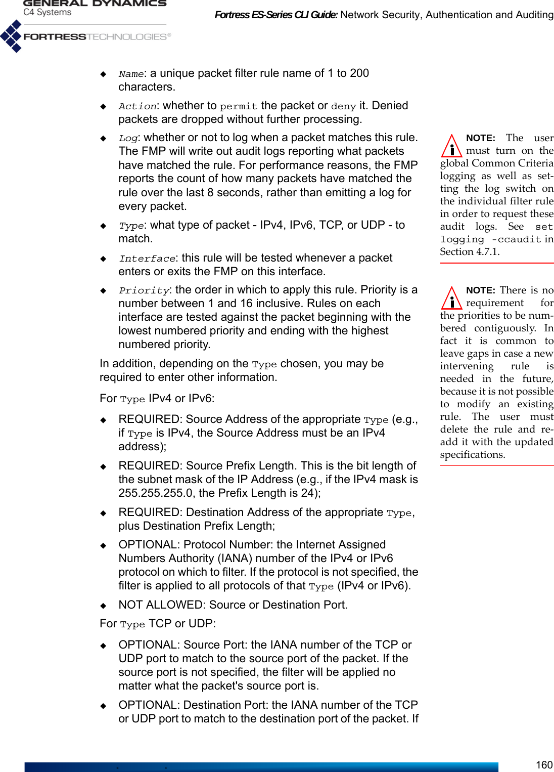
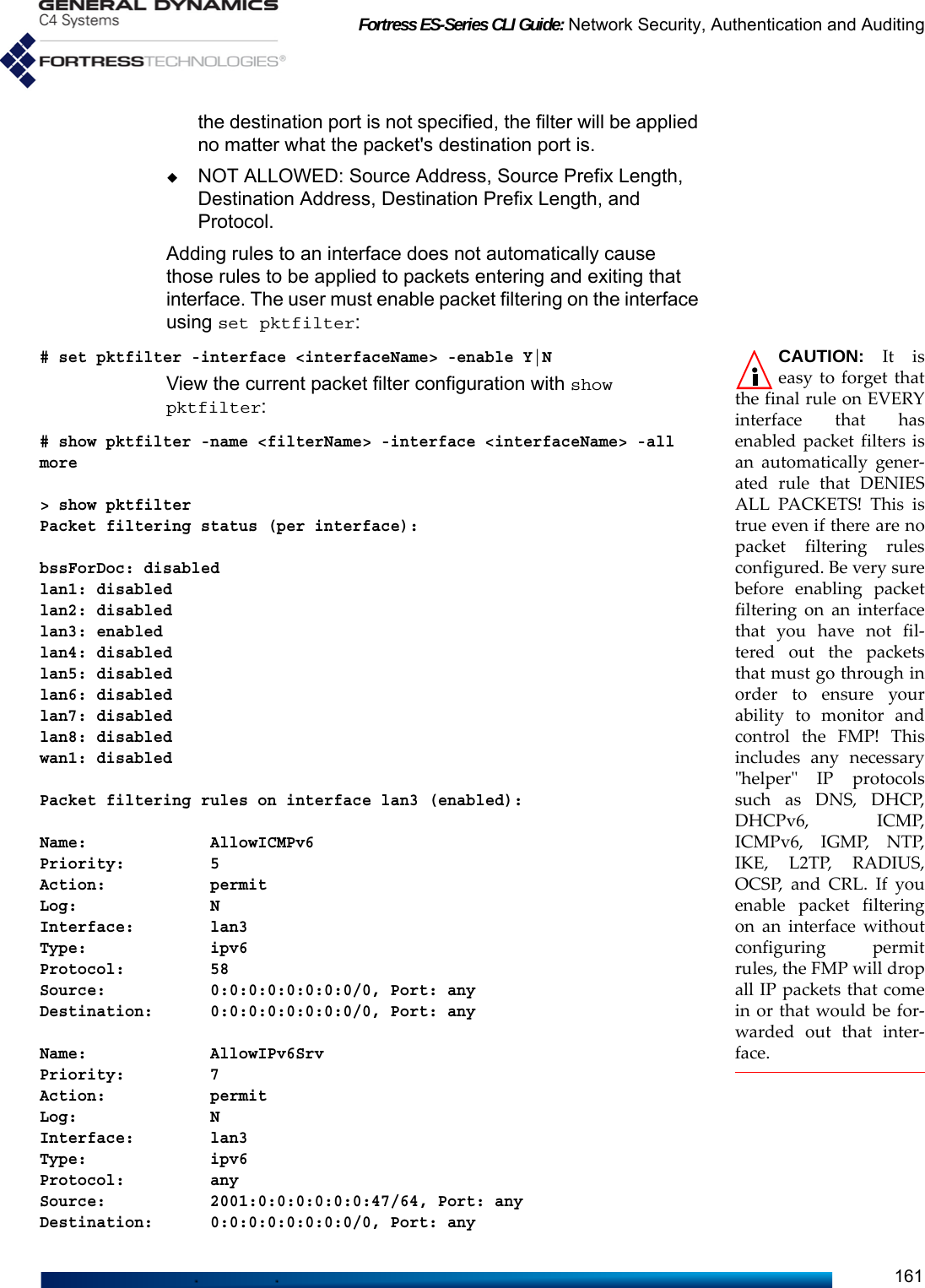
![Fortress ES-Series CLI Guide: Network Security, Authentication and Auditing166it to the Mesh Point configuration. You must also assign either any or at least one port.You can leave out the -state, -passall, and -2way arguments, if the defaults suit your needs. APs are enabled for Fortress Mesh Point management by default, and two-way communication on APs is enabled.Use the update command to change AP settings, as follows:# update ap north# update ap north -name north -ip 192.167.1.44 -mac e1:2b:33:40:0d:5e -2way y -passall n -state disable -ports anyThe update ap command returns the current settings for the specified AP, which you can edit and re-enter: use the left/right arrow keys to navigate displayed fields, backspace over current values or overwrite them. When you finish typing in new values, strike Enter↵ to save them. You can also use the update ap command with only the switches and arguments you need:# update ap east -state enableThe Mesh Point CLI returns [OK] when settings are successfully changed.NOTE: APs thathave been dis-abled or deleted fromMesh Point manage-ment continue to passnetwork traffic.Delete a single AP or all APs from Fortress Mesh Point management with the del ap command, as follows:# del ap -name <APname>|allYou must be logged on to an administrator-level account to execute add, update and del commands (refer to Section 2.2).4.6.5.2 Trusted Devices View configured Trusted Devices with show td:> show tdNAME IP MAC S PORT---------------- --------------- ---------------- - ----audit 192.167.1.13 6f:0a:00:2c:3d:4e N email,fileshareguests 192.167.1.7 3a:b2:3c:4f:55:e6 Y webprint 192.167.1.22 3e:23:f5:d2:01:2a Y fileshare--- Total TDs: 3Use the add, update and del (delete) commands to manage Trusted Devices for the Mesh Point-secured WLAN, as described in the following sections.Add Trusted Devices with the add td command, as follows:# add td -name <TDname> -ip any|<IPaddr> -mac <MACaddr> -state enable|disable -ports any|<portset1,portset2,…>](https://usermanual.wiki/General-Dynamics-Mission-Systems/ES520P/User-Guide-2811717-Page-180.png)
![Fortress ES-Series CLI Guide: Network Security, Authentication and Auditing167NOTE: Each TDname must beunique on the MeshPoint.in which TDname is a descriptive identifier for the Trusted Device, MACaddr is the MAC address of the Trusted Device, and IPaddr either configures the Trusted Device to take any IP address or specifies its network address. The -state switch enables/disables access for the Trusted Device. The -ports switch specifies commonly used port sets, by function, accessible through the Trusted Device (comma delimited, without spaces), or that any port is accessible through the Trusted Device.CAUTION: Specify-ing that any portcan access a TD canpose a significant secu-rity risk.Valid port set values are: web (ports 80, 443)ssh (port 22)snmp (ports 161, 162)email (ports 25, 110, 143, 220)fileshare (ports 137, 138, 139)telnet (port 23)Maximize network security by specifying the narrowest possible port access for Trusted Devices.You must configure a name, MAC address and either any or a specific IP address for the Trusted Device when you add it to the Mesh Point configuration. You must also assign either any or at least one port set.You can leave out the -state switch; Trusted Devices are disabled by default.Use the update command to change Trusted Device settings, as follows:# update td guests # update td guests -name guest -ip 192.167.1.12 -mac 11:2a:3b:4d:56:1a -state enable -ports webThe update td command returns the current settings for the specified Trusted Device, which you can edit and re-enter: use the left/right arrow keys to navigate displayed fields, backspace over current values or overwrite them. When you finish typing in new values, strike Enter↵ to save them. You can also use the td update command with only the switches and arguments you need:# update td guests -name visitorThe Mesh Point CLI returns [OK] when settings are successfully changed.Delete a single Trusted Device or all Trusted Devices from Mesh Point management with the del td command, as follows:# del td <name>|-allYou must be logged on to an administrator-level account to execute add, update and del commands (refer to Section 2.2).](https://usermanual.wiki/General-Dynamics-Mission-Systems/ES520P/User-Guide-2811717-Page-181.png)
![Fortress ES-Series CLI Guide: Network Security, Authentication and Auditing1684.7 Remote Audit Logging When remote audit logging is enabled, the Mesh Point sends audit log messages of the specified severity level (and higher) to the configured external syslog server (Section 4.7.1). Audit-logged administrative and device activity can then be separately filtered by a number of additional parameters (Sections 4.7.2 and 4.7.4).4.7.1 Enabling Audit Logging View the audit logging and syslog server settings currently in effect with show logging:> show loggingEnableAuditMode: YSeverity: criticalEnableRemote: NRemoteHost:Common Criteria Auditing: NNOTE: Audit logmessages are iden-tified as such in the localevent log, but remotelog filtering functionshave no effect on localevent logging.By default, no external syslog server is configured for the Mesh Point. To send log messages from the Mesh Point to an external audit log, you must enable and configure the connection to the syslog server. You can also specify the severity level at and above which log messages are sent to the configured server. By default, only messages of critical or greater severity are forwarded to the audit log.You can also enable Common Criteria audit logs which may impact performance or throughput. These logs include per-interface packet filtering logs and logs reporting traffic drops due to excessive traffic on an interface.# set loggingEnableAuditMode[Y] (Y|N to enable logging audit mode):Severity[info] (emergency|alert|critical|error|warning|notice|info):EnableRemote[N] (Y|N to enable remote logging): y|nRemoteHost[""] (Name or IP address of remote logging host): <IPaddr>|<hostname>EnableCCAudit[N] (Y|N to enable Common Criteria audit logging):You must be logged on to an administrator-level account to configure audit logging (refer to Section 2.2).4.7.2 Globally Filtering Audited Administrative Activity NOTE: Changes toadministrativeaudit logging take effectat the next administra-tor logon.When remote audit logging is enabled, you can filter audited administrative activity globally, by a number of parameters. Globally configured audit-log filters apply only to the activity of administrative accounts with an -audit setting of automatic (Section 2.2.3) and only when the administrator’s MAC address is not subject to conflicting audit-log settings (Section](https://usermanual.wiki/General-Dynamics-Mission-Systems/ES520P/User-Guide-2811717-Page-182.png)
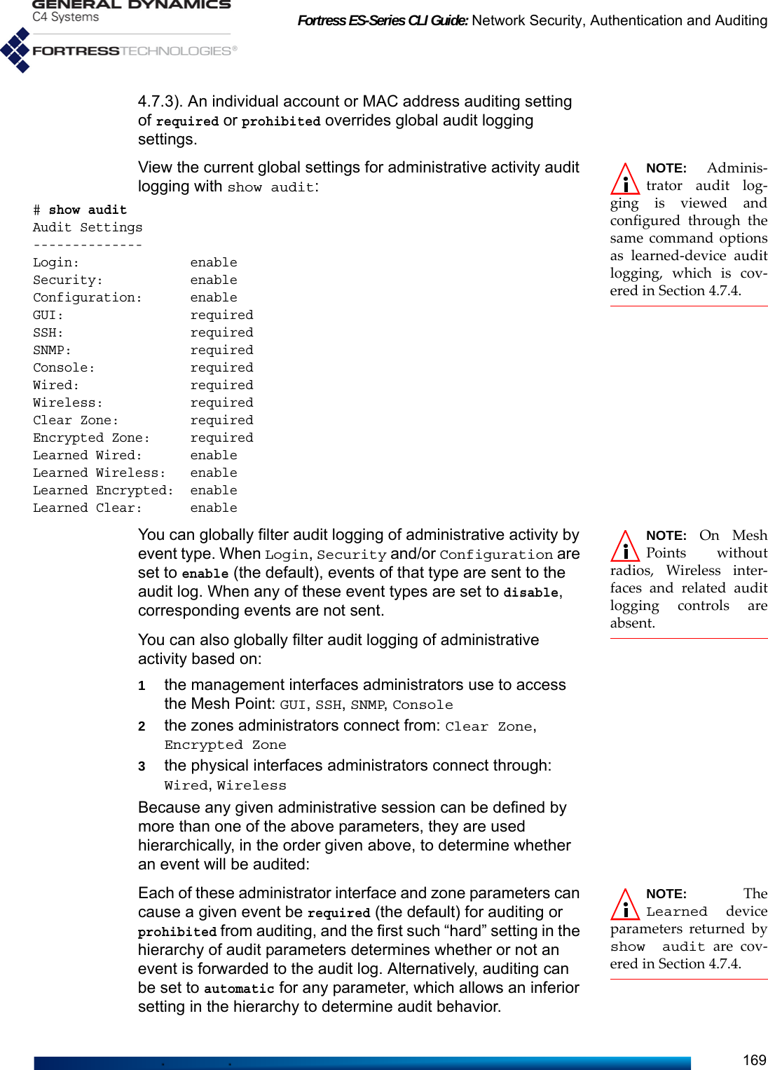
![Fortress ES-Series CLI Guide: Network Security, Authentication and Auditing170Configure global audit logging of administrative activity interactively with set audit:Alternatively, you can execute set audit non-interactively with valid switches and arguments in any order and combination:# set audit -login enable|disable -security enable|disable -configuration enable|disable -GUI required|prohibited|automatic -SSH required|prohibited|automatic -SNMP required|prohibited|automatic -console required|prohibited|automatic -wired required|prohibited|automatic -wireless required|prohibited|automatic -encryptedzone required|prohibited|automatic -clearzone required|prohibited|automatic NOTE: Additionalswitches to config-ure learned deviceauditing with setaudit are covered inSection 4.7.4.The Mesh Point CLI returns [OK] when settings are successfully set. You must be logged on to an administrator-level account to configure audit logging (refer to Section 2.2).4.7.3 Auditing and Filtering Administrative Activity by MAC Address You can specify MAC addresses for audit logging of administrative activity and filter audit events by interface and zone.Audit logging settings for specified MAC addresses override global auditing settings for administrative activity (Section 4.7.2). However, the -audit settings of individual administrative accounts (Section 2.2.3), override MAC-address auditing.View current MAC-address auditing settings with show macaudit:# show macaudit -allMAC Address Description Gui Ssh Snmp Wired Wireless Clear Zone Encrypted Zone----------- ----------- --- --- ---- ----- -------- ---------- --------------By default, no MAC addresses are specified for auditing.# set auditLogin[enable] (enable|disable to enable or disable auditing of logins):Security[enable] (enable|disable to enable or disable auditing of security events):Configuration[enable] (enable|disable to enable or disable auditing of configuration events):GUI[required] (required | prohibited | automatic to enable or disable auditing of events from the GUI):SSH[required] (required | prohibited | automatic to enable or disable auditing of events from access via SSH):SNMP[required] (required | prohibited | automatic to enable or disable auditing of events from access via SNMP):Console[required] (required | prohibited | automatic to enable or disable auditing of events from access via the console):Wired[required] (required | prohibited | automatic to enable or disable auditing of events from access via wired interfaces):Wireless[required] (required | prohibited | automatic to enable or disable auditing of events from access via wireless interfaces):Clear Zone[required] (required | prohibited | automatic to enable or disable auditing of events from access via the clear zone):Encrypted Zone[required] (required | prohibited | automatic to enable or disable auditing of events from access via the encrypted zone):Learned Wired[enable] (enable|disable to enable or disable auditing of learned wired activity):Learned Wireless[enable] (enable|disable to enable or disable auditing of learned wireless activity):Learned Encrypted[enable] (enable|disable to enable or disable auditing of learned wireless activity):Learned Clear[enable] (enable|disable to enable or disable auditing of learned wireless activity):](https://usermanual.wiki/General-Dynamics-Mission-Systems/ES520P/User-Guide-2811717-Page-184.png)
![Fortress ES-Series CLI Guide: Network Security, Authentication and Auditing171When more than one MAC address has been added for audit logging, you can view the individual settings for that MAC address by specifying it:# show macaudit -mac 1a2b3c4d5e6fAdd a MAC address for audit logging of associated administrative activity with add macaudit:# add macaudit -mac <MACaddress> -desc <description|“descriptive string”> -gui required|prohibited|automatic -ssh required|prohibited|automatic -snmp required|prohibited|automatic -encryptedzone required|prohibited|automatic -clearzone required|prohibited|automatic -wired required|prohibited|automatic -wireless required|prohibited|automaticNOTE: On MeshPoints withoutradios, Wireless inter-faces and related auditlogging controls areabsent.The switches following those that specify the MAC address and optionally provide a description configure how audit logging of the administrative activity associated with the specified MAC address will be filtered:1by the management interface used to access the Mesh Point: -gui, -ssh, -snmp2by the zone the MAC address connected from: -clearzone, -encryptedzone3by the physical interfaces the MAC address connected through: -wired, -wirelessBecause an administrative session associated with a given MAC address can be defined by more than one of the above parameters, they are used hierarchically, in the order given above, to determine whether an event will be audited:Each parameter can cause a given event to be required (the default) for auditing or prohibited from auditing, and the first such “hard” setting in the hierarchy of audit parameters determines whether or not an event is forwarded to the audit log. Alternatively, auditing can be set to automatic for any parameter, which allows an inferior setting in the hierarchy to determine audit behavior.Once a MAC address has been added for administrative auditing, you cannot change it. Use the -mac switch with the update command to reconfigure the audit settings for the MAC address you specify. The same switches and arguments used with add macaudit (above) can be used to edit filter settings:# update macaudit -mac <MACaddress> -desc <description|“descriptive string”> -gui required|prohibited|auto -ssh required|prohibited|auto -snmp required|prohibited|auto -encryptedzone required|prohibited|auto -clearzone required|prohibited|auto -wired required|prohibited|auto -wireless required|prohibited|autoThe Mesh Point CLI returns [OK] when settings are successfully changed.](https://usermanual.wiki/General-Dynamics-Mission-Systems/ES520P/User-Guide-2811717-Page-185.png)
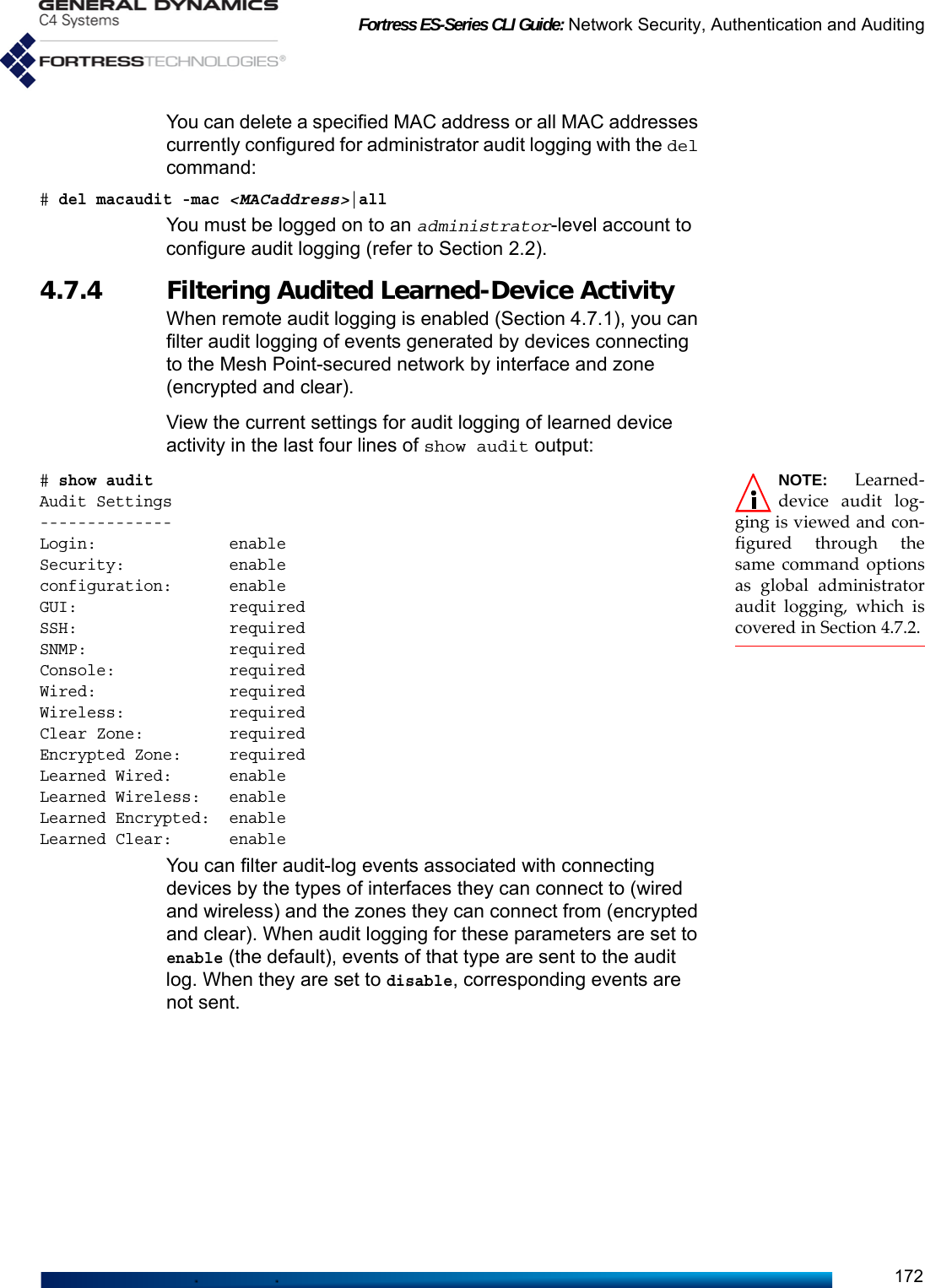
![Fortress ES-Series CLI Guide: Network Security, Authentication and Auditing173Configure audit logging of learned-device activity interactively in the last four fields of set audit:Alternatively, you can execute set audit non-interactively with valid switches and arguments in any order and combination:# set audit -ldwired enable|disable -ldwireless enable|disable -ldencryptedzone enable|disable -ldclearzone enable|disable The Mesh Point CLI returns [OK] when settings are successfully set. You must be logged on to an administrator-level account to configure audit logging (refer to Section 2.2).4.8 Wireless SchedulesThe Mesh Point provides the ability to configure a schedule for session establishments by wireless clients. The Mesh Point supports a single wireless schedule which is applied globally across all configured Access Point (AP) BSSs. When enabled, wireless clients are restricted to establish a session only on the specified days within the specified time range (24 hour format). The time range is applied to all days selected in the schedule. When disabled, wireless clients are allowed to establish a session on any day at any time.View the current wireless schedule with the show command:> show wifischeduleWifi ScheduleAdmin state: enable Days: mon,tue,wed,thur,fri Start time: 08:30End time: 17:30Add the wireless schedule with the add command:# add wifischedule -adminstate <enable/disable> -days <mon,tue,wed,thu,fri,sat,sun> -startTime <hh:mm> -endTime <hh:mm>Delete the wireless schedule with the del command:# del wifischedule# set auditLogin[enable] (enable|disable to enable or disable auditing of logins):Security[enable] (enable|disable to enable or disable auditing of security events):configuration[enable] (enable|disable to enable or disable auditing of configuration events):GUI[required] (required | prohibited | automatic to enable or disable auditing of events from the GUI):SSH[required] (required | prohibited | automatic to enable or disable auditing of events from access via SSH):SNMP[required] (required | prohibited | automatic to enable or disable auditing of events from access via SNMP):Console[required] (required | prohibited | automatic to enable or disable auditing of events from access via the console):Wireded[required] (required | prohibited | automatic to enable or disable auditing of events from access via wired interfaces):Wireless[required] (required | prohibited | automatic to enable or disable auditing of events from access via wireless interfaces):Clear Zone[required] (required | prohibited | automatic to enable or disable auditing of events from access via the clear zone):Encrypted Zone[required] (required | prohibited | automatic to enable or disable auditing of events from access via the encrypted zone):Learned Wired[enable] (enable|disable to enable or disable auditing of learned wired activity):Learned Wireless[enable] (enable|disable to enable or disable auditing of learned wireless activity):Learned Encrypted[enable] (enable|disable to enable or disable auditing of learned wireless activity):Learned Clear[enable] (enable|disable to enable or disable auditing of learned wireless activity):](https://usermanual.wiki/General-Dynamics-Mission-Systems/ES520P/User-Guide-2811717-Page-187.png)

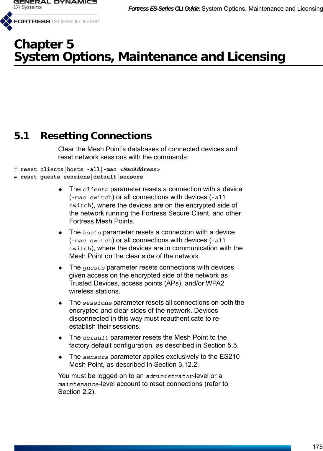
![Fortress ES-Series CLI Guide: System Options, Maintenance and Licensing1765.2 Rebooting the Mesh Point NOTE: The rebootand reset defaultcommands end allactive sessions on theFortress Mesh Point. Restart the Fortress Mesh Point with reboot, confirming your intention at the query, as follows:# rebootConfirm: Reboot device now? [Y|N] yYou can reboot the system after a specified amount of time with -delay. The system automatically reboots after the number of minutes indicated, between 1–1440. A value of 0 (zero) cancels any pending reboot. # reboot -delay 20Confirm: Schedule delayed reboot? [Y|N] y[OK] System will be rebooted after 20 minutes.NOTE: You canalso reboot someMesh Point models withchassis controls (refer tothe appropriate Hard-ware Guide).The reboot command does not power cycle the Mesh Point. When the Mesh Point has rebooted, you must log back in to the Mesh Point CLI. Except for the boot that occurs after you upgrade the Mesh Point’s software, by default the Mesh Point boots the same image, on the same partition, that it used when it last booted. From a serial session, you can interrupt the boot process by striking Ctrl-C, which allows you to choose the software image to boot and optionally reset the Mesh Point to its factory default configuration.You must be logged on to an administrator-level or a maintenance-level account to reboot the Mesh Point (refer to Section 2.2).5.2.1 Booting Selectable Software Images The Mesh Point stores two, user-selectable copies (or images) of the Mesh Point software on separate partitions of the internal flash memory. When the Mesh Point’s software is upgraded (Section 5.3), the new software is first written to the non-running boot partition, overwriting any version stored there. When the Mesh Point is rebooted to complete the upgrade process, it boots from the partition to which the upgrade was downloaded, with the same configuration settings that were in effect before the upgrade procedure.The Mesh Point then defaults to the boot partition with the latest software image—or the last image booted—whenever it restarts. New configuration changes are not written to the non-running boot partition. If you boot from the non-running boot partition, configuration settings will return to those in effect at the time the Mesh Point’s software was last upgraded (or when the image on the partition last ran).](https://usermanual.wiki/General-Dynamics-Mission-Systems/ES520P/User-Guide-2811717-Page-190.png)
![Fortress ES-Series CLI Guide: System Options, Maintenance and Licensing177View which of the two software images on the Mesh Point is currently running and which is selected for the next time the Fortress Mesh Point is booted with show bootimage:> show bootimageImage1: 5.4.3.1058Image2: 5.4.3.1052Running Image1NextRun Image1Use set bootimage to select an image for the next bootCAUTION: If anAvailableImageis listed as Invalid, donot run the image.# set bootimage 1|2[OK] reboot required for next run ImageNYou can also use set bootimage without argument to discover the current running image before making the decision to specify the other image for the next boot.# set bootimageAvailable Image1:5.4.3.1058Available Image2:5.4.3.1052You are running Image1Would you like to switch the Image? [Y|N] y|nThe Mesh Point does not automatically restart when a new boot image is selected. To begin using the software on the image you specified, you must restart the Mesh Point with the reboot command.You must be logged on to an administrator-level account to select a different image for the next boot (refer to Section 2.2).5.3 Upgrading Mesh Point Software View the current software version with the about command (Section 6.1).Upgrades to Mesh Point software are supplied by General Dynamics C4 Systems in the form of upgrade packages, protected by the password, fortress. Upgrade package files must be used on the correct platform model, as distinguished by their file names:ES2-<version.build>.pkg: ES2440ES-<version.build>.pkg: ES820, ES520, ES210When you upgrade Mesh Point software, the new version is written to the non-running compact flash card partition as a new boot image (Section 5.2.1). The existing version of the software currently saved on the non-running flash partition is overwritten by the upgrade process.](https://usermanual.wiki/General-Dynamics-Mission-Systems/ES520P/User-Guide-2811717-Page-191.png)
![Fortress ES-Series CLI Guide: System Options, Maintenance and Licensing178You must specify a path to an FTP server with an anonymous user account in order to successfully execute the upgrade command, or the Mesh Point returns the error:[Error] file must be an FTP url, for example "ftp://ftp.server.com/path/to/gw.pkg"To begin the basic upgrade process, use the upgrade command to specify the location of the upgrade file and its password:# upgrade -f <ftp://ftp.server.com/path/gw.version.pkg> -p fortress -ramdisk y|nCAUTION: If youuse -ramdisk yto upgrade a Mesh Pointwith insufficient RAMto hold the necessarytemporary images, theupgrade will fail. In order to speed the upgrade process, the ES2440 Mesh Point defaults to using RAM (Random Access Memory) to hold the temporary image files used during upgrades. Because the ES520, ES820 and ES210 have less RAM, they default to using internal flash memory to hold these images. You can change this aspect of the upgrade process with the -ramdisk switch: y (yes) to use RAM, n (no) to use flash memory.NOTE: Do not use-ratelimit or-noresume for locallystored upgrade files(with the -e switch,described below).Optionally, you can throttle the download transfer rate for upgrade files stored on an FTP server by specifying an upper -ratelimit in whole megabits per second (Mbits/s), 1–100. To ensure that you are starting fresh with a new download, you can also direct the Mesh Point to refrain from attempting to resume partial downloads of an upgrade file with the -noresume switch, which takes no arguments. If no previously initiated partial download is detected, the upgrade function ignores the -noresume switch.# upgrade -f <ftp://ftp.server.com/path/gw.version.pkg> -p fortress -ratelimit 1–100 -noresumeThe Mesh Point CLI displays the status of the upgrade process, which can take several minutes.After the upgrade has completed, you must reboot the Mesh Point, as described in Section 5.2.If you experience problems after the Mesh Point reboots, revert to the previously running Mesh Point software version (as described in Section 5.2.1), and then retry the upgrade.There are two additional upgrade options exclusively for use in conjunction with the Mesh Point’s Auto-Config function:# upgrade -d -f <ftp://ftp.server.com/path/gw.version.pkg> -p fortress -ratelimit 1–100 -noresumeThe -d switch permits you to store the upgrade file (for distribution and later use), without upgrading the Mesh Point’s current software version.](https://usermanual.wiki/General-Dynamics-Mission-Systems/ES520P/User-Guide-2811717-Page-192.png)
![Fortress ES-Series CLI Guide: System Options, Maintenance and Licensing179# upgrade -e -ramdisk y|nNOTE: After theupgrade andreboot, FastPath Meshwill be the default set-ting for Bridging Mode. Ifyour Mesh Point wasconfigured for STP priorto the upgrade, you mayneed to reconfigure yournetwork accordingly.The -e switch is used to upgrade Mesh Point software using an upgrade file stored in this way, (as opposed to an upgrade file stored on an FTP server). As shown, you can use the -e switch with the -ramdisk option (described above), while -ratelimit and -noresume are not intended for use with locally stored files.These -d and -e switches should not be used during standard upgrade procedures; refer to the Fortress Mesh Point Auto Configuration Guide information.You must be logged on to an administrator-level account to upgrade Mesh Point software (refer to Section 2.2).5.4 Initiating FIPS Retests You can manually run FIPS self tests with set fips:FIPS# set fips retestThe Mesh Point returns [OK] when FIPS tests run successfully.FIPS tests are triggered by any security-related change to the Mesh Point configuration, regardless of FIPS settings. You cannot turn FIPS testing off on the Mesh Point. Failed FIPS tests are recorded in the Mesh Point’s event log.For more on FIPS operating mode and self-tests, refer to Sections 4.1.1 and 4.1.2.5.5 Restoring Defaults NOTE: Installedlicenses for addedfeatures (Section 5.6) areunaffected by resettingthe Mesh Point to factorydefaults.Restore all Fortress Mesh Point configuration settings to their factory default values with reset default, confirming your intention at the query, as follows:# reset defaultWarning: Reset to the default configuration?[Y|N] yWaiting for reset completed...You must be logged on to an administrator-level account to restore factory default settings (refer to Section 2.2).5.6 Features Licensing NOTE: area licenseapplies only toMesh Points with stan-dard-equipment radios(i.e., only 2.4 and/or 5GHz radio-equippedMesh Points). It does notapply to Mesh Pointswith 4.4 GHz radio.There are various optional features on Fortress Mesh Points that you can enable only after entering or uploading valid license keys for these functions.advradio - (advanced radio) enables specialized radio settings. Consult your Fortress representative for more detail.area - (area of operation) permits the Mesh Point to operate within the rules of various regulatory domains and authorities:](https://usermanual.wiki/General-Dynamics-Mission-Systems/ES520P/User-Guide-2811717-Page-193.png)
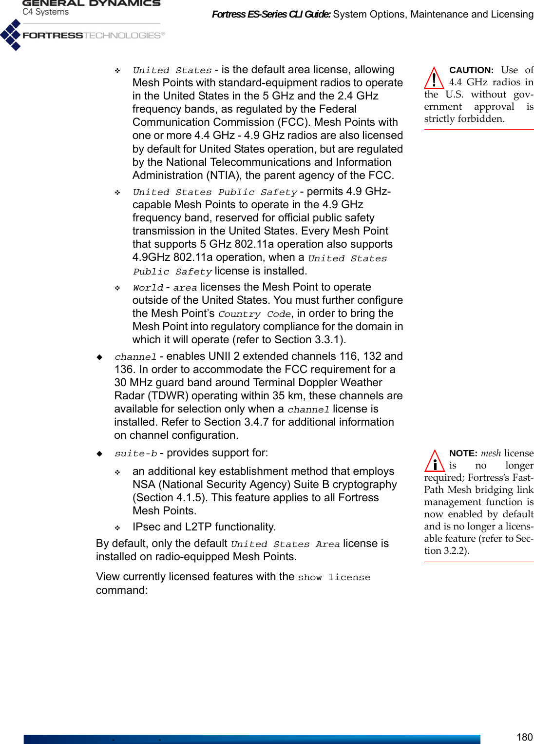
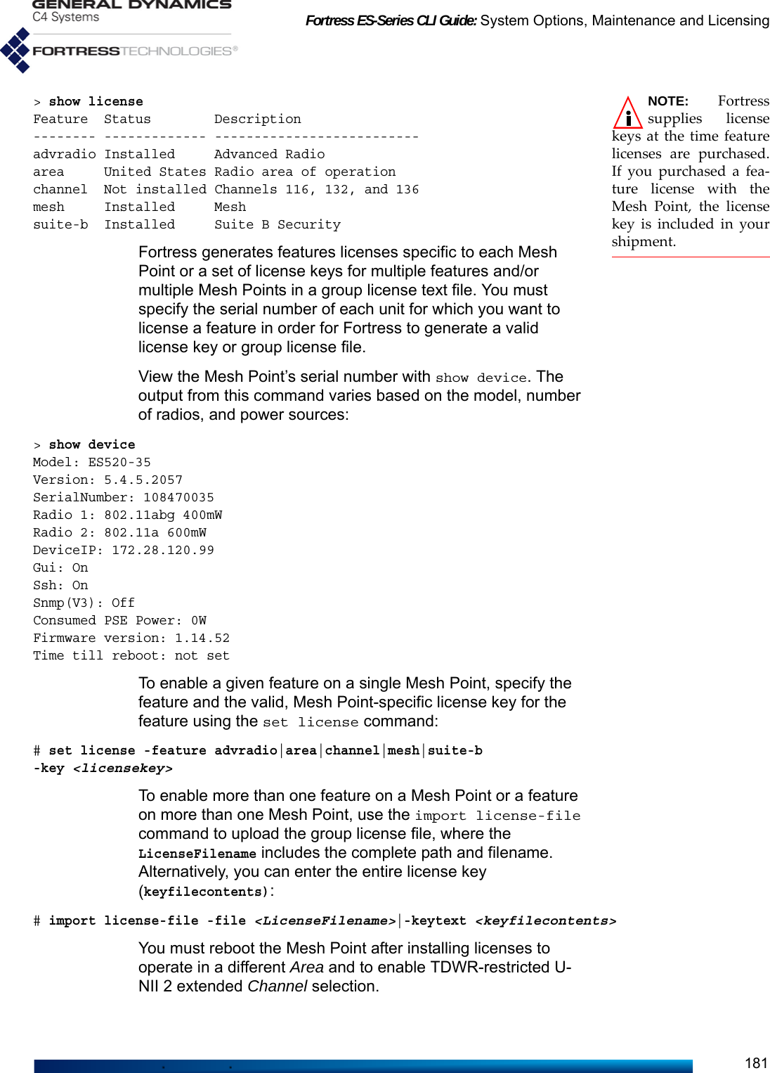
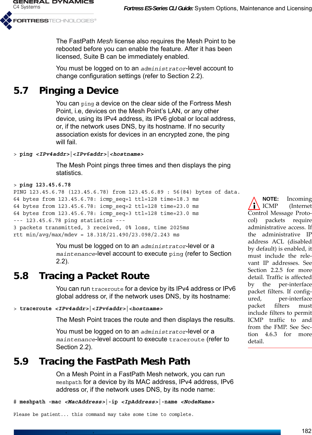
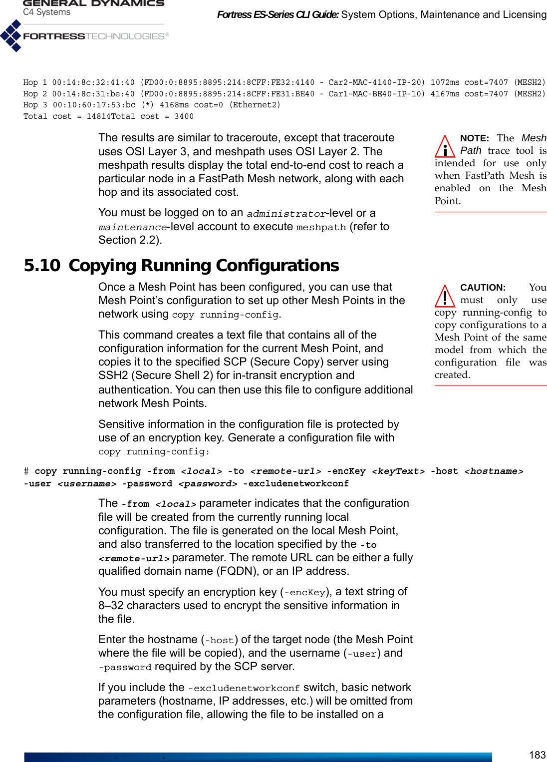
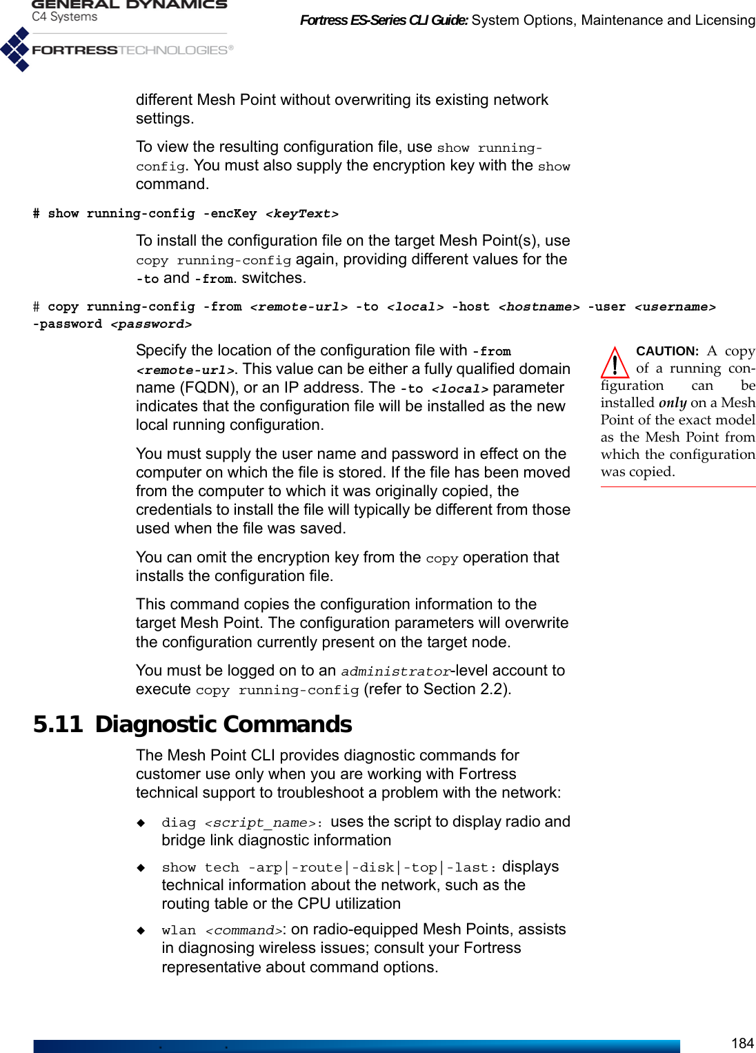
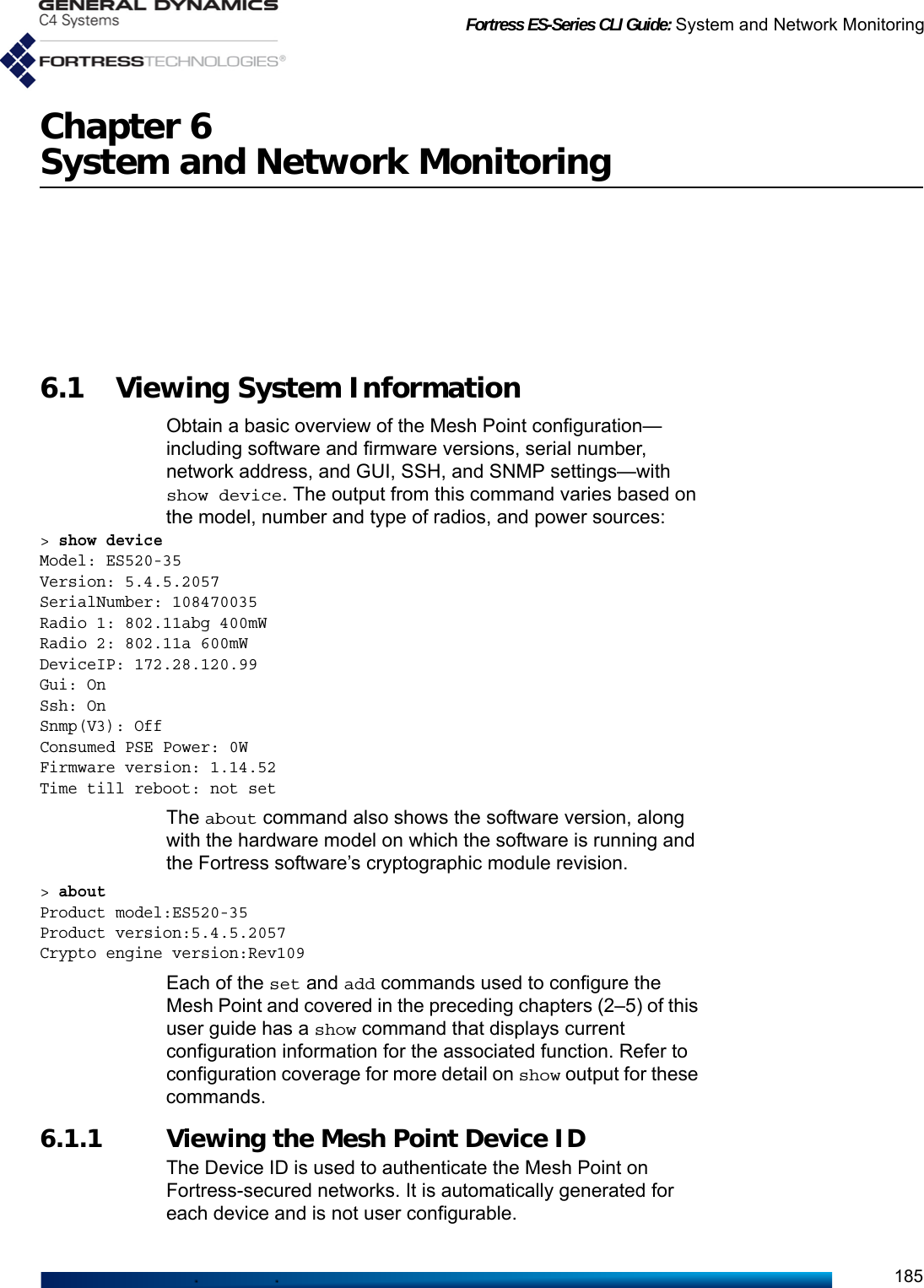
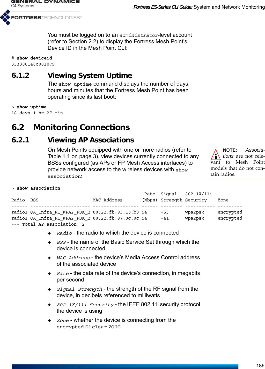
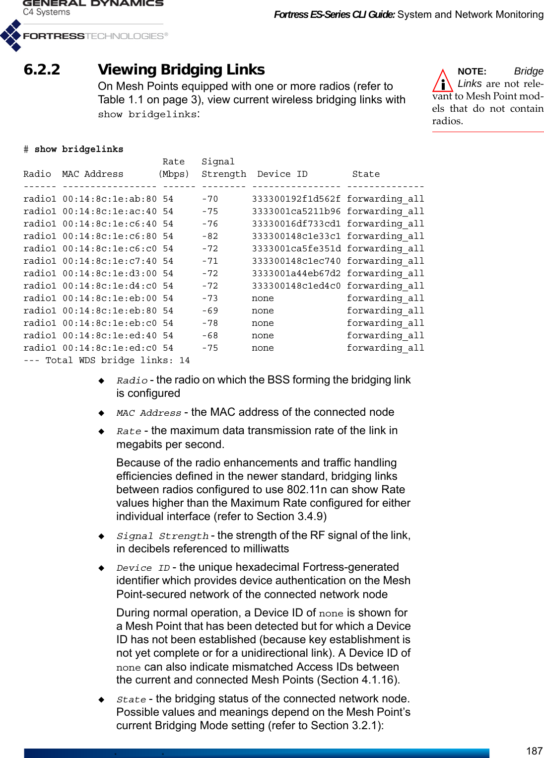
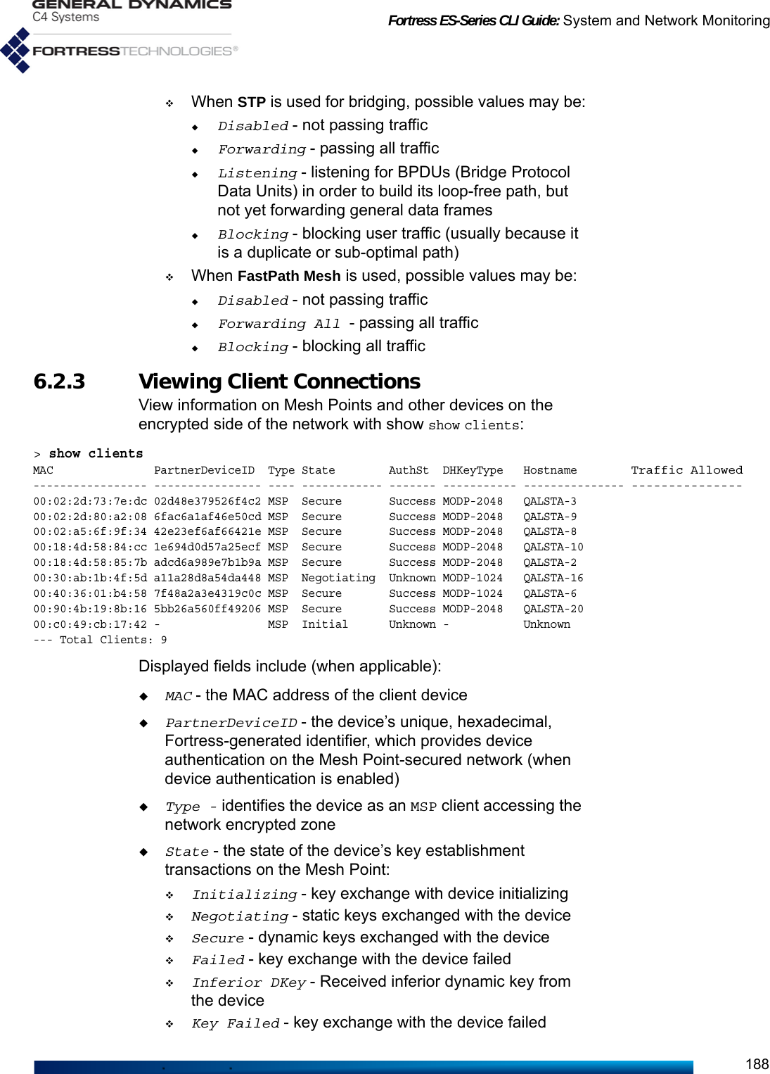
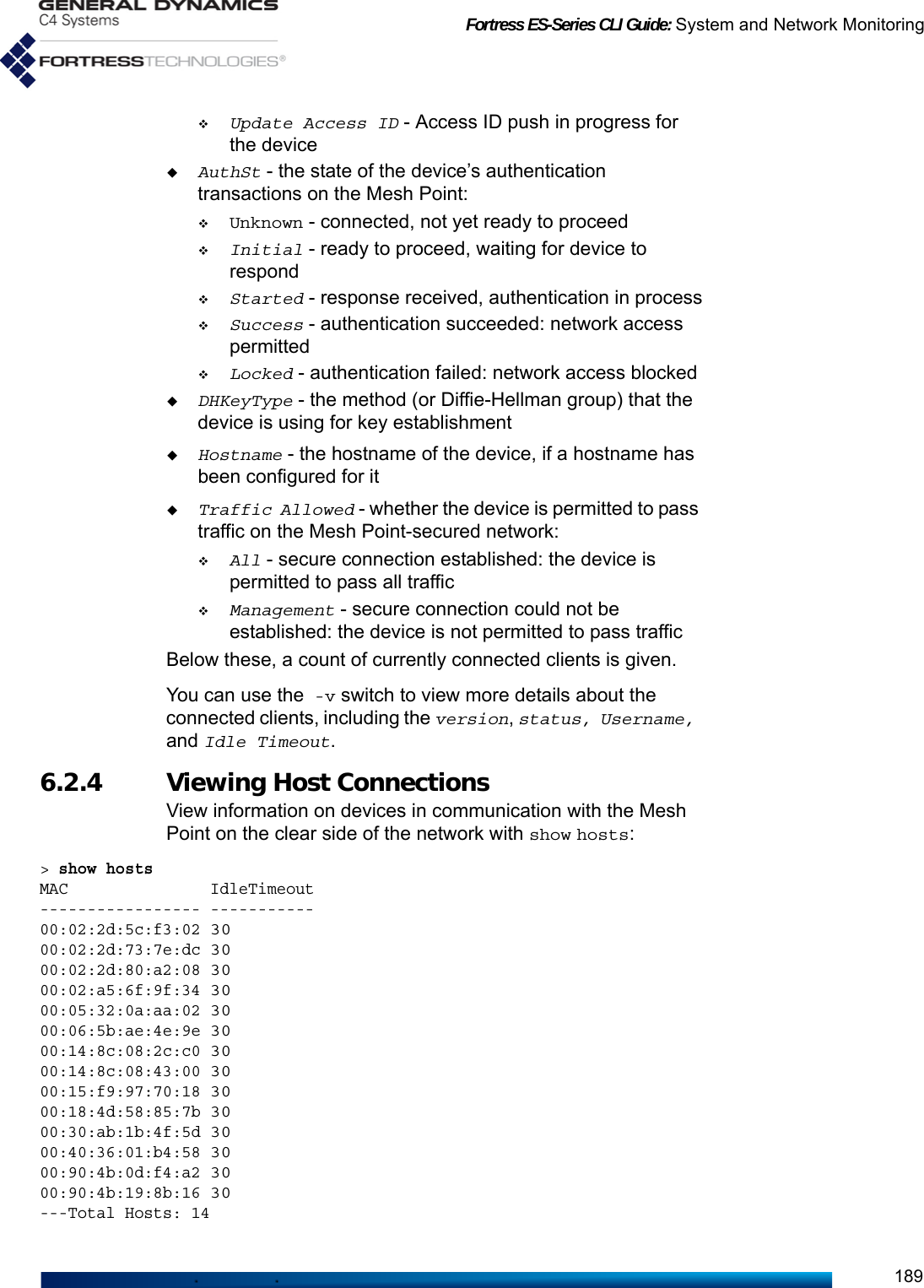
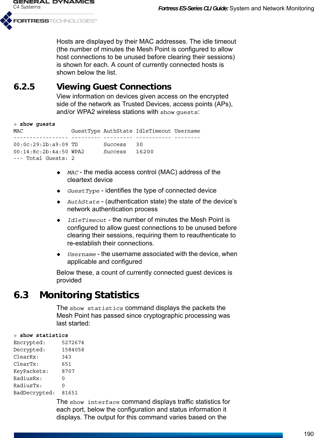
![Fortress ES-Series CLI Guide: System and Network Monitoring191number and type of interfaces on the Mesh Point (refer to Table 1.1 on page 3):# show interface[CONFIGURED INFO] Switching UCost Enable TrafficName Mode VlanId Mode Duplex Speed 8021x Zone MeshIf Offset MeshEncap QoS Class--------- ------- ------ --------- ------ ----- ----- --------- ------ ------ --------- ------ -------Ethernet1 enabled 1 access auto auto N encrypted access 0 N N lowEthernet2 enabled 1 access auto auto N clear access 0 N N low[STATUS INFO]Name Link Duplex Speed Collisions--------- ---- ------ ----- ----------Ethernet1 down half 10 0Ethernet2 up full 100 0[STATISTIC INFO]Name Type State InBytes InPackets InErrTotal OutBytes OutPackets OutErrTotal--------- ----- ---------- ------- --------- ---------- -------- ---------- -----------Ethernet1 wired disabled 0 0 0 0 0 0Ethernet2 wired forwarding 0 0 0 6428477 95865 46.4 IPsec SAs MonitoringWhen a Suite-B license is installed (refer to Section 5.6) and IPsec is enabled and configured (refer to Section 4.4), you can view just the total number of Security Associations established between the Mesh Point and its IPsec peers with show ipsec -sa -counter. # show ipsec -sa -counter3 SAs registeredOmit the -counter switch to view current SAs:# show ipsec -saInbound SPI 0xCEEEECF / outbound SPI 0xCC2D277, crypto suite Suite B 256Peer: 172.28.128.208, local 0.0.0.0/0 <=> remote 172.28.128.208/32Lifetime: 239/240 minutes, unlimited KBInbound SPI 0x2DA5DE79 / outbound SPI 0xDBC63AA, crypto suite Suite B 256Peer: 172.28.128.211, local 0.0.0.0/0 <=> remote 172.28.128.211/32Lifetime: 220/240 minutes, unlimited KBInbound SPI 0x4A2D1748 / outbound SPI 0xD42E2E98, crypto suite Suite B 256Peer: 172.28.128.209, local 0.0.0.0/0 <=> remote 172.28.128.209/32Lifetime: 163/240 minutes, unlimited KB3 SAs registeredExcept for the Lifetime countdown, Inbound SPI and Outbound SPI (Security Parameter Index), the IPsec parameters are configured, globally or per SPD (Security Policy Database) entry, with set ipsec (refer to Section 4.4.1).](https://usermanual.wiki/General-Dynamics-Mission-Systems/ES520P/User-Guide-2811717-Page-205.png)