General Dynamics Mission Systems ES520P Dual radio access point/bridge User Manual CLIguide5 4 5
General Dynamics C4 Systems Dual radio access point/bridge CLIguide5 4 5
User Manual

Fortress Mesh Point
Software CLI Guide
www.gdc4s.com
© 2015 General Dynamics C4 Systems, Inc.

Fortress ES-Series CLI Guide
i
009-00036–00v5.4.5
Fortress Mesh Point Version 5.4.5 Software CLI Guide
Copyright © 2015 General Dynamics C4 Systems, Inc. All rights reserved.
This document contains proprietary information protected by copyright. No part of this
document may be reproduced or transmitted in any form or by any means, electronic or
mechanical, without written permission of General Dynamics C4 Systems, 77 “A” Street,
Needham, MA 02494, except as specified in the Product Warranty and License Terms.
GENERAL DYNAMICS C4 SYSTEMS MAKES NO WARRANTY OF ANY KIND WITH
REGARD TO THIS MATERIAL, INCLUDING BUT NOT LIMITED TO THE IMPLIED
WARRANTIES OF MERCHANTABILITY AND FITNESS FOR A PARTICULAR PURPOSE.
GENERAL DYNAMICS C4 SYSTEMS SHALL NOT BE LIABLE FOR ERRORS
CONTAINED HEREIN OR FOR INCIDENTAL OR CONSEQUENTIAL DAMAGES IN
CONNECTION WITH THE FURNISHING, PERFORMANCE OR USE OF THIS
MATERIAL. THE INFORMATION IN THIS DOCUMENT IS SUBJECT TO CHANGE
WITHOUT NOTICE.
General Dynamics Broadband and General Dynamics C4 Systems | Fortress Technologies
are trademarks of General Dynamics. Fortress Technologies and AirFortress logos and
AirFortress are registered trademarks. Multi-Factor Authentication, Unified Security Model,
Wireless Link Layer Security and Three Factor Authentication (TFA) are trademarks of
General Dynamics C4 Systems, Inc. The technology behind Wireless Link Layer
Security™ enjoys U.S. and international patent protection under patent number 5,757,924.
Portions of this software are covered by the GNU General Public License (GPL) Copyright
© 1989, 1991 Free Software Foundation, Inc,. 51 Franklin Street, Fifth Floor, Boston, MA
02110-1301 USA.
To receive a complete machine-readable copy of the corresponding source code on CD,
send $10 (to cover the costs of production and mailing) to: General Dynamics C4 Systems,
77 “A” Street, Needham, MA 02494. Please be sure to include a copy of your General
Dynamics C4 Systems invoice and a valid “ship to” address.
This product includes cryptographic software written by Eric Young (eay@cryptsoft.com).
This product includes software written by Tim Hudson (tjh@cryptsoft.com).
Copyright © 1995-1998 Eric Young (eay@cryptsoft.com) All rights reserved.
This package is an SSL implementation written by Eric Young (eay@cryptsoft.com). The
implementation was written so as to conform with Netscape’s SSL.
THIS SOFTWARE IS PROVIDED BY ERIC YOUNG ``AS IS'' AND ANY EXPRESS OR
IMPLIED WARRANTIES, INCLUDING, BUT NOT LIMITED TO, THE IMPLIED
WARRANTIES OF MERCHANTABILITY AND FITNESS FOR A PARTICULAR PURPOSE
ARE DISCLAIMED. IN NO EVENT SHALL THE AUTHOR OR CONTRIBUTORS BE
LIABLE FOR ANY DIRECT, INDIRECT, INCIDENTAL, SPECIAL, EXEMPLARY, OR
CONSEQUENTIAL DAMAGES (INCLUDING, BUT NOT LIMITED TO, PROCUREMENT
OF SUBSTITUTE GOODS OR SERVICES; LOSS OF USE, DATA, OR PROFITS; OR
BUSINESS INTERRUPTION) HOWEVER CAUSED AND ON ANY THEORY OF
LIABILITY, WHETHER IN CONTRACT, STRICT LIABILITY, OR TORT (INCLUDING
NEGLIGENCE OR OTHERWISE) ARISING IN ANY WAY OUT OF THE USE OF THIS
SOFTWARE, EVEN IF ADVISED OF THE POSSIBILITY OF SUCH DAMAGE.
Copyright (c) 2010, Atheros Communications Inc. Atheros and the Atheros logo are
trademarks of Atheros Communications, Inc.
THIS SOFTWARE IS PROVIDED "AS IS" AND THE AUTHOR (Atheros Communications,
Inc) DISCLAIMS ALL WARRANTIES WITH REGARD TO THIS SOFTWARE INCLUDING
ALL IMPLIED WARRANTIES OF MERCHANTABILITY AND FITNESS. IN NO EVENT
SHALL THE AUTHOR BE LIABLE FOR ANY SPECIAL, DIRECT, INDIRECT, OR
CONSEQUENTIAL DAMAGES OR ANY DAMAGES WHATSOEVER RESULTING FROM
LOSS OF USE, DATA OR PROFITS, WHETHER IN AN ACTION OF CONTRACT,
NEGLIGENCE OR OTHER TORTIOUS ACTION, ARISING OUT OF OR IN
CONNECTION WITH THE USE OR PERFORMANCE OF THIS SOFTWARE.

Fortress ES-Series CLI Guide
ii
This product uses Dynamic Host Control Protocol, Copyright © 2004–2010 by Internet
Software Consortium, Inc. Copyright © 1995–2003 by Internet Software Consortium. All
rights reserved.
This product includes software developed by the OpenSSL Project for use in the OpenSSL
Toolkit. (http://www.openssl.org/)
Copyright © 1998-2011 The OpenSSL Project. All rights reserved. THIS SOFTWARE IS
PROVIDED BY THE OpenSSL PROJECT ``AS IS'' AND ANY EXPRESSED OR IMPLIED
WARRANTIES, INCLUDING, BUT NOT LIMITED TO, THE IMPLIED WARRANTIES OF
MERCHANTABILITY AND FITNESS FOR A PARTICULAR PURPOSE ARE
DISCLAIMED. IN NO EVENT SHALL THE OpenSSL PROJECT OR ITS CONTRIBUTORS
BE LIABLE FOR ANY DIRECT, INDIRECT, INCIDENTAL, SPECIAL, EXEMPLARY, OR
CONSEQUENTIAL DAMAGES (INCLUDING, BUT NOT LIMITED TO, PROCUREMENT
OF SUBSTITUTE GOODS OR SERVICES; LOSS OF USE, DATA, OR PROFITS; OR
BUSINESS INTERRUPTION) HOWEVER CAUSED AND ON ANY THEORY OF
LIABILITY, WHETHER IN CONTRACT, STRICT LIABILITY, OR TORT (INCLUDING
NEGLIGENCE OR OTHERWISE) ARISING IN ANY WAY OUT OF THE USE OF THIS
SOFTWARE, EVEN IF ADVISED OF THE POSSIBILITY OF SUCH DAMAGE.
This product uses Net-SNMP. Copyright 1989, 1991, 1992 by Carnegie Mellon University.
Derivative Work - 1996, 1998-2000. Copyright 1996, 1998-2000 The Regents of the
University of California. All rights reserved. Copyright (c) 2001-2003, Networks Associates
Technology, Inc. All rights reserved. Portions of this code are copyright (c) 2001-2003,
Cambridge Broadband Ltd. All rights reserved. Copyright © 2003 Sun Microsystems, Inc.,
4150 Network Circle, Santa Clara, California 95054, U.S.A. All rights reserved. Copyright
(c) 2003-2008, Sparta, Inc. All rights reserved. Copyright (c) 2004, Cisco, Inc and
Information Network Center of Beijing University of Posts and Telecommunications. All
rights reserved. Copyright (c) Fabasoft R&D Software GmbH & Co KG, 2003
oss@fabasoft.com. Author: Bernhard Penz bernhard.penz@fabasoft.com.
THIS SOFTWARE IS PROVIDED BY THE COPYRIGHT HOLDERS AND
CONTRIBUTORS ``AS IS'' AND ANY EXPRESS OR IMPLIED WARRANTIES,
INCLUDING, BUT NOT LIMITED TO, THE IMPLIED WARRANTIES OF
MERCHANTABILITY AND FITNESS FOR A PARTICULAR PURPOSE ARE
DISCLAIMED. IN NO EVENT SHALL THE COPYRIGHT HOLDERS OR
CONTRIBUTORS BE LIABLE FOR ANY DIRECT, INDIRECT, INCIDENTAL, SPECIAL,
EXEMPLARY, OR CONSEQUENTIAL DAMAGES (INCLUDING, BUT NOT LIMITED TO,
PROCUREMENT OF SUBSTITUTE GOODS OR SERVICES; LOSS OF USE, DATA, OR
PROFITS; OR BUSINESS INTERRUPTION) HOWEVER CAUSED AND ON ANY
THEORY OF LIABILITY, WHETHER IN CONTRACT, STRICT LIABILITY, OR TORT
(INCLUDING NEGLIGENCE OR OTHERWISE) ARISING IN ANY WAY OUT OF THE USE
OF THIS SOFTWARE, EVEN IF ADVISED OF THE POSSIBILITY OF SUCH DAMAGE.
Licensed under the Apache License, Version 2.0 (the "License"); you may not use this file
except in compliance with the License. You may obtain a copy of the License at http://
www.apache.org/licenses/LICENSE-2.0. Unless required by applicable law or agreed to in
writing, software distributed under the License is distributed on an "AS IS" BASIS,
WITHOUT WARRANTIES OR CONDITIONS OF ANY KIND, either express or implied.
See the License for the specific language governing permissions and limitations under the
License.
Microsoft and Windows are registered trademarks of the Microsoft Corporation.
Firefox is a trademark of the Mozilla Foundation.
SSH is a trademark of SSH Communication Security.
All other trademarks mentioned in this document are the property of their respective
owners.
End User License Agreement (EULA) and Limited Software
Warranty – Fortress Products

Fortress ES-Series CLI Guide
iii
IMPORTANT; PLEASE READ THIS END USER LICENSE AGREEMENT CAREFULLY.
DOWNLOADING, INSTALLING OR USING GENERAL DYNAMICS C4 SYSTEMS’
SOFTWARE CONSTITUTES ACCEPTANCE OF THIS AGREEMENT.
GENERAL DYNAMICS C4 SYSTEMS, INC., WILL LICENSE ITS SOFTWARE TO YOU
THE CUSTOMER (END USER) ONLY UPON THE CONDITION THAT YOU ACCEPT
ALL OF THE TERMS CONTAINED IN THIS END USER LICENSE AGREEMENT. THE
ACT OF DOWNLOADING, INSTALLING, OR USING FORTRESS SOFTWARE, BINDS
YOU AND THE BUSINESS THAT YOU REPRESENT (COLLECTIVELY, “CUSTOMER”)
TO THE AGREEMENT.
License
General Dynamics C4 Systems, Inc. (“Fortress”) grants to Customer (“Licensee”) a non-
exclusive and non-transferable right to use the Fortress Software Product (“Software”)
described in the Fortress Product Description for which Customer has paid any required
license fees and subject to the use rights and limitations in this EULA. Unless otherwise
agreed to in writing, use of the Software is limited to the number of authorized users for
which Licensee has purchased the right to the use of the software. Software is authorized
for installation on any Fortress approved device. “Software” includes computer program(s)
and any documentation (whether contained in user manuals, technical manuals, training
materials, specifications, etc.) that
i
s included with the software (including CD-ROM, or
on-line). Software is authorized for installation on a single use computing device such
as Fortress hardware platform, computer, laptop, PDA or any other computing
device
.
Software is not licensed for installation or embedded use on any other system(s)
controlling access to a secondary network of devices or securing access for any separate
computing devices. Software contains proprietary technology of Fortress. No ownership in
or title to the Software is transferred. Software is protected by copyright laws and
international treaties. Customer may be required to input a software license key to initialize
the software installation process.
Customer may make backup or archival copies of Software and use Software on a backup
processor temporarily in the event of a processor malfunction. Any full or partial copy of
Software must include all copyright and other proprietary notices which appear on or in
the Software. Control functions may be installed and enabled. Customer may not modify
control utilities. Customer may not disclose or make available Software to any other party
or permit others to use it except Customer’s employees and agents who use it on
Customer’s behalf and who have agreed to these license terms. Customer agrees not to
reverse engineer, decompile, or disassemble the Software. Customer shall maintain
adequate records matching the use of Software to license grants and shall make the
records available to Fortress or the third party developer or owner of the Software on
reasonable notice. Unless the Customer is a branch of the United States Government,
Fortress may terminate any license granted hereunder if Customer breaches any license
term. Upon termination of the Agreement, Customer shall destroy or return to Fortress all
copies of Software.
General Limitations
This is a License for the use of Fortress Software Product and documentation; it is not a
transfer of title. Fortress retains ownership of all copies of the Software and
Documentation. Customer acknowledges that Fortress trade secrets are contained
within the Software and Documentation. Except as otherwise expressly provided under the
Agreement, Customer shall have no right and Customer specifically agrees not to:
i. Transfer, assign or sublicense its license rights to any other person or entity and
Customer acknowledges that any attempt to transfer, assign or sublicense shall “void”
the license;
ii. Make modifications to or adapt the Software or create a derivative work based on the
Software, or permit third parties to do the same;
iii. Reverse engineer, decompile, or disassemble the Software to a human-readable
form, except to the extent otherwise expressly permitted under applicable law
notwithstanding this restriction; and

Fortress ES-Series CLI Guide
iv
iv. Di
v. sclose, provide, or otherwise make available trade secrets contained within the
Software and Documentation in any form to any third party without the prior written
consent of Fortress. Customer shall implement reasonable security measures to
protect such trade secrets.
Software, Upgrades and Additional Copies
For purposes of the Agreement, “Software” shall include computer programs, including
firmware, as provided to Customer by Fortress and any (a) bug fixes, (b) maintenance
releases, (c) minor and major upgrades as deemed to be included under this EULA by
Fortress or backup copies of any of the foregoing.
NOTWITHSTANDING ANY OTHER PROVISION OF THE AGREEMENT:
i. CUSTOMER HAS NO LICENSE OR RIGHT TO MAKE OR USE ANY ADDITIONAL
COPIES OR UPGRADES UNLESS CUSTOMER, AT THE TIME OF MAKING OR
ACQUIRING SUCH COPY OR UPGRADE, ALREADY HOLDS A VALID LICENSE
TO THE ORIGINAL SOFTWARE AND HAS PAID THE APPLICABLE FEE FOR THE
UPGRADE OR ADDITIONAL COPIES;
ii. USE OF UPGRADES IS LIMITED TO FORTRESS EQUIPMENT FOR WHICH
CUSTOMER IS THE ORIGINAL END USER CUSTOMER OR LESSEE OR
OTHERWISE HOLDS A VALID LICENSE TO USE THE SOFTWARE WHICH IS
BEING UPGRADED; AND
iii. THE MAKING AND USE OF ADDITIONAL COPIES IS LIMITED TO NECESSARY
BACKUP PURPOSES ONLY.
Proprietary Notices
All copyright and other proprietary notices on all copies of the Software shall be maintained
and reproduced by the Customer in the same manner that such copyright and other
proprietary notices are included on the Software. Customer shall not make any copies or
duplicates of any Software without the prior written permission of Fortress; except as
expressly authorized in the Agreement.
Term and Termination
This EULA shall remain in effect until terminated through one of the following
circumstances:
i. At any time by Customer’s destruction of all copies of the Software and any
Documentation.
ii. By Fortress due to Customer non-compliance with any provision of the Agreement
(not applicable to U.S. Government C
ustomers).
iii. A
iv. ny United States Government Customer non-compliance and/or breach of the
terms of this Agreement shall be handled in accordance with the provisions of the
Contracts Disputes Act of 1978, as amended.
Upon termination by either the Customer or Fortress, the Customer shall destroy or return
to Fortress all copies of Software and Documentation in its possession or control. All
limitations of liability, disclaimers, restrictions of warranty, and all confidentiality
obligations of Customer shall survive termination of this Agreement. Also, the provisions
set-forth in the sections titled “U.S. Government Customers” and “General Terms
Applicable to the Limited Warranty Statement and End User License Agreement” shall
survive termination of the Agreement.
Customer Records
For Commercial Customers: Fortress and its independent accountants reserve the right
to conduct an audit of Customer records to verify compliance with this agreement.
Customer grants to Fortress and its independent accountants access to its books, records
and accounts during Customer’s normal business hours in support of such an audit.
Customer shall pay to Fortress the appropriate license fees, plus the reasonable cost of
conducting the audit should an audit disclose non- compliance with this Agreement.

Fortress ES-Series CLI Guide
v
For U.S. Government Customers: United States Government Customers agree to review
usage monitor logs, software
lo
gs and other relevant Customer records to verify
Customer’s compliance with this Agreement and to promptly inform Fortress of any
violation of their obligations hereunder and to promptly enter into discussions with
Fortress and any relevant prime contractor to discuss the payment of reasonable costs
and reasonable attorneys’ fees within the Contracts Disputes Act of 1978, as amended.
Export Restrictions
Customer acknowledges that the laws and regulations of the United States restrict the
export and
re
-export of certain commodities and technical data of United States origin,
including the Product, Software and the Documentation, in any medium. Customer will
not knowingly, without prior authorization if required, export or re-export the Product,
Software or the Documentation in any medium without the appropriate United States and
foreign government licenses. The transfer or export of the software outside the U.S. may
require a license from the Bureau of Industry and Security. For questions call BIS at 202-
482-4811.
U.S. Government Customers
The Software and associated documentation were developed at private expense and are
delivered and licensed as “commercial computer software” as defined in DFARS 252.227-
7013, DFARS 252.227-7014, or DFARS 252.227-7015 as a “commercial item” as defined
in FAR 2.101(a), or as “Restricted computer software” as defined in FAR
52.227
-19. All
other technical data, including manuals or instructional materials, are provided with “Limited
Rights” as defined in DFAR 252.227-7013 (a) (15), or FAR 52.227-14 (a) and in Alternative
II (JUN 1987) of that clause, as applicable.
General Terms Applicable to the Limited Warranty and End User License Agreement
Limited Warranty
The warranties provided by Fortress in this Statement of Limited Warranty apply only to
Fortress
P
roducts purchased from Fortress for internal use on Customer’s computer
network. “Product” means a Fortress software product, upgrades, or firmware, or any
combination thereof. The term “Product” also includes Fortress software programs,
whether pre-loaded with the Fortress hardware Product, installed subsequently or
otherwise. Nothing in this Statement of Warranty affects any statutory rights of consumers
that cannot be waived or limited by contract.
Customer is responsible for determining the suitability of the Products in Customer’s
network environment. Unless otherwise agreed, Customer is responsible for the Product’s
installation, set-up, configuration, and for password and digital signature management.
Fortress warrants the Products will conform to the published specifications and will be
free of defects in materials and workmanship. Customer must notify Fortress within the
specified warranty period of any claim of such defect. The warranty period for software is
one (1) year commencing from the ship date to Customer. The date of shipment is
established per the shipping document (packing list) for the Product that is shipped from
Fortress location.
Customer shall provide Fortress with access to the Product to enable Fortress to diagnose
and correct any errors or defects. If the Product is found defective by Fortress, Fortress’
sole obligation under this warranty is to remedy such defect at Fortress’ option through
repair, upgrade or replacement of product. Services and support provided to diagnose a
reported issue with a Fortress Product, which is then determined not to be the root cause
of the issue, may, at Fortress’ option be billed at the standard time and material rates.
Warranty Exclusions
The warranty does not cover Fortress Hardware Product or any other equipment upon
which the Software is authorized by Fortress or its suppliers or licensors, which (a) has
been damaged through abuse or negligence or by accident, (b) has been altered except
by an authorized Fortress representative, (c) has been subjected to abnormal physical or
electrical stress
(i.
e., lightning strike) or abnormal environmental conditions (i.e., beyond
the published specifications), (d) has been lost or damaged in transit, or (e) has not been

Fortress ES-Series CLI Guide
vi
installed, operated, repaired or maintained in accordance with instructions provided by
Fortress.
The warranty is voided by removing any tamper evidence security sticker or marking
except as performed by a Fortress authorized service technician.
Fortress does not warrant uninterrupted or error-free operation of any Products or third
party software, including public domain software which may have been incorporated into
the Fortress Product.
Fortress will bear no responsibility with respect to any defect or deficiency resulting from
accidents, misuse, neglect, modifications, or deficiencies in power or operating
environment.
Unless specified otherwise, Fortress does not warrant or support non-Fortress products. If
any service or support is rendered such support is provided WITHOUT WARRANTIES OF
ANY KIND.
Governing Law
For Commercial Customers: This Agreement shall be governed by and construed in
accordance with the laws of the State of New York without reference to its conflict of laws
rules.
For U.S. Government Customers: This Agreement shall be governed by and construed in
accordance with United States Federal statutory and common law. The United States
Federal Courts shall have exclusive jurisdiction over any claim arising under this
Agreement.
Disclaimer of Liabilities
THE FOREGOING WARRANTIES ARE THE EXCLUSIVE WARRANTIES AND
REPLACE ALL OTHER WARRANTIES OR CONDITIONS, EXPRESS OR IMPLIED,
INCLUDING, BUT NOT LIMITED TO, THE IMPLIED WARRANTIES OR CONDITIONS
OF MERCHANTABILITY AND FITNESS FOR A PARTICULAR PURPOSE. FORTRESS
SHALL HAVE NO LIABILITY FOR CONSEQUENTIAL, EXEMPLARY, OR INCIDENTAL
DAMAGES EVEN IF IT HAS BEEN ADVISED OF THE POSSIBILITY OF SUCH
DAMAGES. THE STATED LIMITED WARRANTY IS IN LIEU OF ALL LIABILITIES OR
OBLIGATIONS OF FORTRESS FOR DAMAGES ARISING OUT OF OR IN
CONNECTION WITH THE DELIVERY, USE, OR PERFORMANCE OF THE PRODUCTS
(HARDWARE AND SOFTWARE). THESE WARRANTIES GIVE SPECIFIC LEGAL
RIGHTS AND CUSTOMER MAY ALSO HAVE OTHER RIGHTS WHICH VARY FROM
JURISDICTION TO JURISDICTION. SOME JURISDICTIONS DO NOT ALLOW THE
EXCLUSION OR LIMITATION OF EXPRESS OR IMPLIED WARRANTIES, SO THE
ABOVE EXCLUSION OR LIMITATION MAY NOT APPLY TO YOU. IN THAT EVENT,
SUCH WARRANTIES ARE LIMITED IN DURATION TO THE WARRANTY PERIOD. NO
WARRANTIES APPLY AFTER THAT PERIOD.
Indemnification
Fortress will defend any action brought against Customer based on a claim that any
Fortress Product infringes any U.S. patents or copyrights excluding third party software,
provided that Fortress is immediately notified in writing and Fortress has the right to
control the defense of all such claims, lawsuits, and other proceedings. If, as a result of
any claim of infringement against any U.S. patent or copyright, Fortress is enjoined from
using the Product, or if Fortress believes the Product is likely to become the subject of a
claim of infringement, Fortress at its option and expense may procure the right for
Customer to continue to use the Product, or replace or modify the Product so as to make it
non-infringing. If neither of these two options is reasonably practicable, Fortress may
discontinue the license granted herein on one month’s written notice and refund to
Licensee the unamortized portion of the license fees hereunder. The depreciation shall be
an equal amount per year over the life of the Product as established by Fortress. The
foregoing states the entire liability of Fortress and the sole and exclusive remedy of the
Customer with respect to infringement of third party intellectual property.

Fortress ES-Series CLI Guide
vii
Limitation of Liability
Circumstances may arise where, because of a default on Fortress’ part or other liability,
Customer is entitled to recover damages from Fortress. In each such instance,
regardless of the basis on which you are entitled to claim damages from Fortress
(including breach, negligence, misrepresentation, or other contract or tort claim), Fortress
is liable for no more than damages for bodily injury (including death) and damage to real
property and tangible personal property, and the amount of any other actual direct
damages, up to either U.S. $25,000 (or equivalent in local currency) or the charges (if
recurring, 12 months’ charges apply) for the Product that is the subject of the claim,
whichever is less. The foregoing is the maximum amount for which Fortress is
responsible.
UNDER NO CIRCUMSTANCES IS FORTRESS LIABLE FOR ANY OF THE FOLLOWING:
1) THIRD-PARTY CLAIMS AGAINST YOU FOR DAMAGES,
2) LOSS OF, OR DAMAGE TO, YOUR RECORDS OR DATA, OR
3) SPECIAL, INCIDENTAL, OR INDIRECT DAMAGES OR FOR ANY ECONOMIC
CONSEQUENTIAL DAMAGES (INCLUDING LOST PROFITS OR SAVINGS), EVEN
IF FORTRESS OR ITS SOLUTION PROVIDER IS INFORMED OF THEIR
POSSIBILITY. SOME JURISDICTIONS DO NOT ALLOW THE EXCLUSION OR
LIMITATION OF INCIDENTAL OR CONSEQUENTIAL DAMAGES, SO THE ABOVE
LIMITATION OR EXCLUSION MAY NOT APPLY TO CUSTOMER.
Telephone Support
During the warranty period, Fortress will provide a reasonable amount of telephone
consultation to the Customer. This support shall include assistance in connection with the
installation and routine operation of the Product, but does not include network
troubleshooting, security consultation, design and other services outside of the scope of
routine Product operation. Warranty services for the Products shall be available during
Fortress’ normal U.S. (EST) business days and hours.
Extended Warranty Service
If the Customer purchases an extended warranty service agreement with Fortress, service
will be provided in accordance to said agreement’s terms and conditions.
Access and Service
Customer must provide Fortress or Solution Provider with access to the Product to enable
Fortress to provide the service. Access may include access via the Internet, on-site
access or Customer shall be responsible for returning the Product to Fortress. Fortress
will notify the Customer to obtain authorization to perform any repairs.
If, during the warranty period, as established by the date of shipment, the Customer finds
any significant defect in materials and workmanship under normal use and operating
conditions, the Customer shall notify Fortress Customer Service in accordance with the
Fortress Service Policies in effect at that time.
DISCLAIMER OF WARRANTY
THE WARRANTIES HEREIN ARE SOLE AND EXCLUSIVE, AND NO OTHER
WARRANTY, WHETHER WRITTEN OR ORAL, IS EXPRESSED OR IMPLIED. TO THE
EXTENT PERMITTED BY LAW, FORTRESS SPECIFICALLY DISCLAIMS THE IMPLIED
WARRANTIES OF MERCHANTABILITY, FITNESS FOR A PARTICULAR PURPOSE,
TITLE AND NONINFRINGEMENT.
EULA Addendum for Products Containing 4.4 GHz Radio(s)
This product contains one or more radios which operate in the 4.4 GHz - 4.9 GHz
range.
The 4.4 GHz - 4.9 GHz frequency range is regulated by the United States National
Telecommunications and Information Administration (NTIA) and allocated exclusively for
government use.
By accepting this agreement, user acknowledges that proper authorization to operate in
this frequency has been obtained and user accepts full responsibility for any unauthorized

Fortress ES-Series CLI Guide
viii
use. User agrees to indemnify and hold harmless General Dynamics C4 Systems, Inc. from
any fines, costs or expenses resulting from or associated with unauthorized use of this
frequency range.
This EULA Addendum does not apply to Fortress products that do not contain 4.4 GHz
radios.

Fortress ES-Series CLI Guide: Table of Contents
ix
Table of Contents
1
Introduction 1
This Document. . . . . . . . . . . . . . . . . . . . . . . . . . . . . . . . . . . . . . . . . .1
Related Documents . . . . . . . . . . . . . . . . . . . . . . . . . . . . . . . . . . . . . . . . . . . . 1
Network Security Overview . . . . . . . . . . . . . . . . . . . . . . . . . . . . . . . .2
Fortress Security Systems. . . . . . . . . . . . . . . . . . . . . . . . . . . . . . . . .2
Fortress Hardware Devices . . . . . . . . . . . . . . . . . . . . . . . . . . . . . . . . . . . . . . 2
ES-Series Model Numbers . . . . . . . . . . . . . . . . . . . . . . . . . . . . . . . . . . . . . . . . . . . . . . .3
Fortress Mesh Point Management . . . . . . . . . . . . . . . . . . . . . . . . . . . . . . . . . . . . . . . . .4
Fortress Software and Hardware Clients. . . . . . . . . . . . . . . . . . . . . . . . . . . . 5
Network Deployment Options . . . . . . . . . . . . . . . . . . . . . . . . . . . . . .5
2
Mesh Point CLI and Administrative Access 7
Mesh Point CLI . . . . . . . . . . . . . . . . . . . . . . . . . . . . . . . . . . . . . . . . .7
Accessing the Mesh Point CLI via the Serial Console Port . . . . . . . . . . . . . . 8
Accessing the Mesh Point CLI Remotely. . . . . . . . . . . . . . . . . . . . . . . . . . . . 8
Logging On and Off the Mesh Point CLI . . . . . . . . . . . . . . . . . . . . . . . . . . . . 8
Accessing Mesh Point CLI Help . . . . . . . . . . . . . . . . . . . . . . . . . . . . . . . . . 10
Command Syntax . . . . . . . . . . . . . . . . . . . . . . . . . . . . . . . . . . . . . . . . . . . . 11
Administrative Accounts and Access. . . . . . . . . . . . . . . . . . . . . . . . 12
Global Administrator Settings . . . . . . . . . . . . . . . . . . . . . . . . . . . . . . . . . . . 13
Password Complexity and Expiration . . . . . . . . . . . . . . . . . . . . . . . . . . . . . . . . . . . . . . 14
Login, Session and Lockout Behaviors . . . . . . . . . . . . . . . . . . . . . . . . . . . . . . . . . . . . . 14
Authentication Method and Failback . . . . . . . . . . . . . . . . . . . . . . . . . . . . . . . . . . . . . . . 15
Administrator Logon Banner . . . . . . . . . . . . . . . . . . . . . . . . . . . . . . . . . . . . 18
Individual Administrator Accounts . . . . . . . . . . . . . . . . . . . . . . . . . . . . . . . . 19
Adding Administrator Accounts . . . . . . . . . . . . . . . . . . . . . . . . . . . . . . . . . . . . . . . . . . . 20
Updating and Deleting Administrator Accounts . . . . . . . . . . . . . . . . . . . . . . . . . . . . . . . 21
Changing Administrative Passwords . . . . . . . . . . . . . . . . . . . . . . . . . . . . . . 21
Administrative IP Address Access Control List . . . . . . . . . . . . . . . . . . . . . . 22
SNMP Settings . . . . . . . . . . . . . . . . . . . . . . . . . . . . . . . . . . . . . . . . . . . . . . 23

Fortress ES-Series CLI Guide: Table of Contents
x
3
Networking and Radio Configuration 27
Network Interfaces. . . . . . . . . . . . . . . . . . . . . . . . . . . . . . . . . . . . . . 27
Network Bridging . . . . . . . . . . . . . . . . . . . . . . . . . . . . . . . . . . . . . . . 28
Bridging Configuration . . . . . . . . . . . . . . . . . . . . . . . . . . . . . . . . . . . . . . . . . 29
FastPath Mesh Bridging . . . . . . . . . . . . . . . . . . . . . . . . . . . . . . . . . . . . . . . 30
Multicast Snooping . . . . . . . . . . . . . . . . . . . . . . . . . . . . . . . . . . . . . . . . . . . . . . . . . . . . 32
Configuring Neighbor Cost Overrides . . . . . . . . . . . . . . . . . . . . . . . . . . . . . . . . . . . . . . 33
Fine-tuning FastPath Mesh Network Performance . . . . . . . . . . . . . . . . . . . 33
Selecting the FastPath Mesh Multicast Transmit Mode. . . . . . . . . . . . . . . . . . . . . . . . . 34
Setting the FastPath Mesh Packet Interval . . . . . . . . . . . . . . . . . . . . . . . . . . . . . . . . . . 34
Setting the FastPath Mesh Transmit Control Level . . . . . . . . . . . . . . . . . . . . . . . . . . . . 35
Setting Multicast Video Clamping Thresholds . . . . . . . . . . . . . . . . . . . . . . . . . . . . . . . . 35
Setting Mesh Routing Reactivity . . . . . . . . . . . . . . . . . . . . . . . . . . . . . . . . . . . . . . . . . . 36
Setting Mesh Packet Time To Live . . . . . . . . . . . . . . . . . . . . . . . . . . . . . . . . . . . . . . . . 36
Viewing Current Mesh Performance Parameters . . . . . . . . . . . . . . . . . . . . . . . . . . . . . 37
Frame Processor Parameters . . . . . . . . . . . . . . . . . . . . . . . . . . . . . . . . . . . . . . . . . . . . 37
STP Bridging . . . . . . . . . . . . . . . . . . . . . . . . . . . . . . . . . . . . . . . . . . . . . . . . 37
Global Radio Settings . . . . . . . . . . . . . . . . . . . . . . . . . . . . . . . . . . . 38
Country Code and Regulatory Authorities . . . . . . . . . . . . . . . . . . . . . . . . . . 39
Environment Setting . . . . . . . . . . . . . . . . . . . . . . . . . . . . . . . . . . . . . . . . . . 40
Unit of Distance Measure . . . . . . . . . . . . . . . . . . . . . . . . . . . . . . . . . . . . . . 41
Radio Frequency Kill . . . . . . . . . . . . . . . . . . . . . . . . . . . . . . . . . . . . . . . . . . 41
Channel Sharing . . . . . . . . . . . . . . . . . . . . . . . . . . . . . . . . . . . . . . . . . . . . . 42
Individual Radio Settings . . . . . . . . . . . . . . . . . . . . . . . . . . . . . . . . . 43
Radio Band, Short Preamble, Guard Interval . . . . . . . . . . . . . . . . . . . . . . . 46
Channel Selection . . . . . . . . . . . . . . . . . . . . . . . . . . . . . . . . . . . . . . . . . . . . 48
Distance, Beacon Interval, Noise Immunity. . . . . . . . . . . . . . . . . . . . . . . . . 52
Network Type, Antenna Gain, Tx Power . . . . . . . . . . . . . . . . . . . . . . . . . . . 53
MIMO. . . . . . . . . . . . . . . . . . . . . . . . . . . . . . . . . . . . . . . . . . . . . . . . . . . . . . 53
STBC . . . . . . . . . . . . . . . . . . . . . . . . . . . . . . . . . . . . . . . . . . . . . . . . . . . . . . 54
Channel Lock and Other Channel Selection Features . . . . . . . . . . . . . . . . 55
DFS, TDWR, and Channel Exclusion . . . . . . . . . . . . . . . . . . . . . . . . . . . . . 56
Dynamic Frequency Selection . . . . . . . . . . . . . . . . . . . . . . . . . . . . . . . . . . . . . . . . . . . . 56
Licensed TDWR Channels . . . . . . . . . . . . . . . . . . . . . . . . . . . . . . . . . . . . . . . . . . . . . . 57
Channel Exclusion. . . . . . . . . . . . . . . . . . . . . . . . . . . . . . . . . . . . . . . . . . . . . . . . . . . . . 57
Radio BSS Settings . . . . . . . . . . . . . . . . . . . . . . . . . . . . . . . . . . . . . . . . . . . 58
BSS Radio, BSS Name and SSID . . . . . . . . . . . . . . . . . . . . . . . . . . . . . . . . . . . . . . . . . 58
WDS Bridging or AP Infrastructure Configuration . . . . . . . . . . . . . . . . . . . . . . . . . . . . . 60
BSS State, SSID Advertising and Drop Probe Requests . . . . . . . . . . . . . . . . . . . . . . . 60
BSS STA Idle Timeout and 802.11g-Only Settings . . . . . . . . . . . . . . . . . . . . . . . . . . . . 60
BSS Unicast Transmission Rate Settings . . . . . . . . . . . . . . . . . . . . . . . . . . . . . . . . . . . 61
BSS WMM QoS Setting. . . . . . . . . . . . . . . . . . . . . . . . . . . . . . . . . . . . . . . . . . . . . . . . . 63
BSS Fragmentation and RTS Thresholds . . . . . . . . . . . . . . . . . . . . . . . . . . . . . . . . . . . 63
BSS DTIM Beacon Countdown . . . . . . . . . . . . . . . . . . . . . . . . . . . . . . . . . . . . . . . . . . . 64
BSS VLANs Settings . . . . . . . . . . . . . . . . . . . . . . . . . . . . . . . . . . . . . . . . . . . . . . . . . . . 65

Fortress ES-Series CLI Guide: Table of Contents
xi
BSS Fortress Security Zone . . . . . . . . . . . . . . . . . . . . . . . . . . . . . . . . . . . . . . . . . . . . . 65
FastPath Mesh BSS Cost Offset . . . . . . . . . . . . . . . . . . . . . . . . . . . . . . . . . . . . . . . . . . 65
BSS Multicast Settings . . . . . . . . . . . . . . . . . . . . . . . . . . . . . . . . . . . . . . . . . . . . . . . . . 66
Bridging MTU and Beacon Encryption . . . . . . . . . . . . . . . . . . . . . . . . . . . . . . . . . . . . . 66
BSS Description . . . . . . . . . . . . . . . . . . . . . . . . . . . . . . . . . . . . . . . . . . . . . . . . . . . . . . 66
BSS Wi-Fi Security Configuration . . . . . . . . . . . . . . . . . . . . . . . . . . . . . . . . . . . . . . . . . 67
Antenna Tracking / Rate Monitoring . . . . . . . . . . . . . . . . . . . . . . . . . . . . . . 69
ES210 Mesh Point STA Settings and Operation . . . . . . . . . . . . . . . . . . . . . 70
STA Radio, Name, SSID and SSID Roaming . . . . . . . . . . . . . . . . . . . . . . . . . . . . . . . . 71
STA State . . . . . . . . . . . . . . . . . . . . . . . . . . . . . . . . . . . . . . . . . . . . . . . . . . . . . . . . . . . 72
STA Unicast Transmission Rate Settings . . . . . . . . . . . . . . . . . . . . . . . . . . . . . . . . . . . 72
STA Background Scanning . . . . . . . . . . . . . . . . . . . . . . . . . . . . . . . . . . . . . . . . . . . . . . 73
STA WMM QoS Setting. . . . . . . . . . . . . . . . . . . . . . . . . . . . . . . . . . . . . . . . . . . . . . . . . 73
STA Fragmentation and RTS Thresholds . . . . . . . . . . . . . . . . . . . . . . . . . . . . . . . . . . . 74
STA Multicast Rate . . . . . . . . . . . . . . . . . . . . . . . . . . . . . . . . . . . . . . . . . . . . . . . . . . . . 74
STA Description. . . . . . . . . . . . . . . . . . . . . . . . . . . . . . . . . . . . . . . . . . . . . . . . . . . . . . . 74
STA Wi-Fi Security Configuration . . . . . . . . . . . . . . . . . . . . . . . . . . . . . . . . . . . . . . . . . 74
Editing or Deleting a STA Interface Connection . . . . . . . . . . . . . . . . . . . . . . . . . . . . . . 76
Establishing a STA Interface Connection . . . . . . . . . . . . . . . . . . . . . . . . . . . . . . . . . . . 76
ES210 Station Access Control Lists . . . . . . . . . . . . . . . . . . . . . . . . . . . . . . . . . . . . . . . 78
Local Area Network Configuration . . . . . . . . . . . . . . . . . . . . . . . . . . 78
Hostname and IPv4 Settings . . . . . . . . . . . . . . . . . . . . . . . . . . . . . . . . . . . . 79
IPv6 Settings . . . . . . . . . . . . . . . . . . . . . . . . . . . . . . . . . . . . . . . . . . . . . . . . 80
DNS Client Settings. . . . . . . . . . . . . . . . . . . . . . . . . . . . . . . . . . . . . . . . . . . 81
Time and Location Configuration. . . . . . . . . . . . . . . . . . . . . . . . . . . 82
System Date and Time . . . . . . . . . . . . . . . . . . . . . . . . . . . . . . . . . . . . . . . . 82
Time Zone . . . . . . . . . . . . . . . . . . . . . . . . . . . . . . . . . . . . . . . . . . . . . . . . . . 83
NTP Client Configuration . . . . . . . . . . . . . . . . . . . . . . . . . . . . . . . . . . . . . . . 83
GPS and Location Configuration . . . . . . . . . . . . . . . . . . . . . . . . . . . 86
DHCP and DNS Services . . . . . . . . . . . . . . . . . . . . . . . . . . . . . . . . 87
Enabling DHCP Services. . . . . . . . . . . . . . . . . . . . . . . . . . . . . . . . . . . . . . . 87
Enabling DNS Servers and Adding External DNS Servers . . . . . . . . . . . . . 89
Enabling Multicast DNS. . . . . . . . . . . . . . . . . . . . . . . . . . . . . . . . . . . . . . . . 90
Ethernet Interfaces . . . . . . . . . . . . . . . . . . . . . . . . . . . . . . . . . . . . . 90
Quality of Service. . . . . . . . . . . . . . . . . . . . . . . . . . . . . . . . . . . . . . . 94
VLANs Implementation . . . . . . . . . . . . . . . . . . . . . . . . . . . . . . . . . . 97
Global VLAN Settings . . . . . . . . . . . . . . . . . . . . . . . . . . . . . . . . . . . . . . . . . 100
Network Interface VLAN Settings . . . . . . . . . . . . . . . . . . . . . . . . . . . . . . . . 102
VLANs and FastPath Mesh . . . . . . . . . . . . . . . . . . . . . . . . . . . . . . . . . . . . .102
ES210 Mesh Point Serial Port Settings . . . . . . . . . . . . . . . . . . . . . .103
Configuring the Serial Port. . . . . . . . . . . . . . . . . . . . . . . . . . . . . . . . . . . . . . 104
Resetting the Serial Port . . . . . . . . . . . . . . . . . . . . . . . . . . . . . . . . . . . . . . . 105
Mesh Viewer Protocol Settings . . . . . . . . . . . . . . . . . . . . . . . . . . . .105

Fortress ES-Series CLI Guide: Table of Contents
xii
4
Network Security, Authentication and Auditing 109
Fortress Security Settings . . . . . . . . . . . . . . . . . . . . . . . . . . . . . . . .109
Operating Mode. . . . . . . . . . . . . . . . . . . . . . . . . . . . . . . . . . . . . . . . . . . . . . 109
FIPS Settings. . . . . . . . . . . . . . . . . . . . . . . . . . . . . . . . . . . . . . . . . . . . . . . . 111
MSP Encryption Algorithm. . . . . . . . . . . . . . . . . . . . . . . . . . . . . . . . . . . . . . 113
Encrypted Data Compression . . . . . . . . . . . . . . . . . . . . . . . . . . . . . . . . . . . 114
MSP Key Establishment . . . . . . . . . . . . . . . . . . . . . . . . . . . . . . . . . . . . . . . 114
MSP Re-Key Interval . . . . . . . . . . . . . . . . . . . . . . . . . . . . . . . . . . . . . . . . . . 115
Key Beacon Interval. . . . . . . . . . . . . . . . . . . . . . . . . . . . . . . . . . . . . . . . . . . 115
Fortress Legacy Devices . . . . . . . . . . . . . . . . . . . . . . . . . . . . . . . . . . . . . . . 115
Encrypted Zone Cleartext Traffic. . . . . . . . . . . . . . . . . . . . . . . . . . . . . . . . . 116
Encrypted Zone Management Settings . . . . . . . . . . . . . . . . . . . . . . . . . . . . 116
Encrypted Interface Management Access . . . . . . . . . . . . . . . . . . . . . . . . . . . . . . . . . . .116
Authorized Cleartext Device Management Access . . . . . . . . . . . . . . . . . . . . . . . . . . . .117
Authorized Wireless Client Management Settings. . . . . . . . . . . . . . . . . . . . 117
Turning Mesh Point GUI Access Off and On . . . . . . . . . . . . . . . . . . . . . . . . 117
SSH Access to the Mesh Point CLI . . . . . . . . . . . . . . . . . . . . . . . . . . . . . . . 119
Disabling and Enabling SSH Access to the Mesh Point CLI . . . . . . . . . . . . . . . . . . . . .119
Configuring Public Key Authentication . . . . . . . . . . . . . . . . . . . . . . . . . . . . . . . . . . . . .119
Blackout Mode. . . . . . . . . . . . . . . . . . . . . . . . . . . . . . . . . . . . . . . . . . . . . . . 120
Allow Cached Credentials . . . . . . . . . . . . . . . . . . . . . . . . . . . . . . . . . . . . . . 120
Fortress Access ID . . . . . . . . . . . . . . . . . . . . . . . . . . . . . . . . . . . . . . . . . . . 121
Digital Certificates . . . . . . . . . . . . . . . . . . . . . . . . . . . . . . . . . . . . . .121
Generating CSRs and Key Pairs . . . . . . . . . . . . . . . . . . . . . . . . . . . . . . . . . 121
Managing Local Certificates . . . . . . . . . . . . . . . . . . . . . . . . . . . . . . . . . . . . 122
Importing and Deleting Certificates . . . . . . . . . . . . . . . . . . . . . . . . . . . . . . . . . . . . . . . .123
Assigning Stored Certificates to Mesh Point Functions . . . . . . . . . . . . . . . . . . . . . . . . .124
Managing the Certificate Revocation List . . . . . . . . . . . . . . . . . . . . . . . . . . . . . . . . . . .126
Access Control Entries . . . . . . . . . . . . . . . . . . . . . . . . . . . . . . . . . .127
Internet Protocol Security . . . . . . . . . . . . . . . . . . . . . . . . . . . . . . . .129
Global IPsec Settings . . . . . . . . . . . . . . . . . . . . . . . . . . . . . . . . . . . . . . . . . 130
Interface Security Policy Database Entries . . . . . . . . . . . . . . . . . . . . . . . . . 132
Dynamic Endpoints for IPsec. . . . . . . . . . . . . . . . . . . . . . . . . . . . . . . . . . . . 134
Dynamic Endpoints for FastPath Mesh Networks . . . . . . . . . . . . . . . . . . . . . . . . . . . . .135
Dynamic Endpoints for VPN Client Connections. . . . . . . . . . . . . . . . . . . . . . . . . . . . . .135
IPsec Pre-Shared Keys . . . . . . . . . . . . . . . . . . . . . . . . . . . . . . . . . . . . . . . . 138
IPsec Access Control Lists . . . . . . . . . . . . . . . . . . . . . . . . . . . . . . . . . . . . .139
L2TP/IPsec Connections . . . . . . . . . . . . . . . . . . . . . . . . . . . . . . . . . . . . . . . 140
Authentication and Timeouts . . . . . . . . . . . . . . . . . . . . . . . . . . . . .142
Authentication Servers. . . . . . . . . . . . . . . . . . . . . . . . . . . . . . . . . . . . . . . . . 142
Internal Authentication Server . . . . . . . . . . . . . . . . . . . . . . . . . . . . . . . . . . . 145
Basic Internal Authentication Server Settings . . . . . . . . . . . . . . . . . . . . . . . . . . . . . . . .146
Certificate Authority Settings . . . . . . . . . . . . . . . . . . . . . . . . . . . . . . . . . . . . . . . . . . . . .146

Fortress ES-Series CLI Guide: Table of Contents
xiii
Global User and Device Authentication Settings. . . . . . . . . . . . . . . . . . . . . . . . . . . . . .146
Local 802.1X Authentication Settings . . . . . . . . . . . . . . . . . . . . . . . . . . . . . . . . . . . . . .147
OCSP Authentication Server Settings . . . . . . . . . . . . . . . . . . . . . . . . . . . . . . . . . . . . . .148
OCSP Cache Settings and Management . . . . . . . . . . . . . . . . . . . . . . . . . . . . . . . . . . .150
Internal Authentication Server Access Control Lists . . . . . . . . . . . . . . . . . . . . . . . . . . .152
User Authentication . . . . . . . . . . . . . . . . . . . . . . . . . . . . . . . . . . . . . . . . . . . 153
Client Device Authentication . . . . . . . . . . . . . . . . . . . . . . . . . . . . . . . . . . . . 154
Session Idle Timeouts . . . . . . . . . . . . . . . . . . . . . . . . . . . . . . . . . . . . . . . . . 156
ACLs and Cleartext Devices . . . . . . . . . . . . . . . . . . . . . . . . . . . . . .157
MAC Address Access Control . . . . . . . . . . . . . . . . . . . . . . . . . . . . . . . . . . . 157
Destination MAC Address Filter. . . . . . . . . . . . . . . . . . . . . . . . . . . . . . . . . . 158
IP Address Packet Filter . . . . . . . . . . . . . . . . . . . . . . . . . . . . . . . . . . . . . . . 159
Packet Filtering on Ingress and Egress. . . . . . . . . . . . . . . . . . . . . . . . . . . . . . . . . . . . .163
ICMPv6 Neighbor Discovery Alert . . . . . . . . . . . . . . . . . . . . . . . . . . . . . . . . . . . . . . . . .163
Fortress Controller Access Control . . . . . . . . . . . . . . . . . . . . . . . . . . . . . . . 163
Cleartext Device Access Control . . . . . . . . . . . . . . . . . . . . . . . . . . . . . . . . . 165
3rd-Party AP Management . . . . . . . . . . . . . . . . . . . . . . . . . . . . . . . . . . . . . . . . . . . . . .165
Trusted Devices. . . . . . . . . . . . . . . . . . . . . . . . . . . . . . . . . . . . . . . . . . . . . . . . . . . . . . .166
Remote Audit Logging . . . . . . . . . . . . . . . . . . . . . . . . . . . . . . . . . . .168
Enabling Audit Logging . . . . . . . . . . . . . . . . . . . . . . . . . . . . . . . . . . . . . . . . 168
Globally Filtering Audited Administrative Activity. . . . . . . . . . . . . . . . . . . . . 168
Auditing and Filtering Administrative Activity by MAC Address . . . . . . . . . . 170
Filtering Audited Learned-Device Activity . . . . . . . . . . . . . . . . . . . . . . . . . . 172
Wireless Schedules . . . . . . . . . . . . . . . . . . . . . . . . . . . . . . . . . . . . .173
5
System Options, Maintenance and Licensing 175
Resetting Connections. . . . . . . . . . . . . . . . . . . . . . . . . . . . . . . . . . .175
Rebooting the Mesh Point . . . . . . . . . . . . . . . . . . . . . . . . . . . . . . . .176
Booting Selectable Software Images. . . . . . . . . . . . . . . . . . . . . . . . . . . . . . 176
Upgrading Mesh Point Software . . . . . . . . . . . . . . . . . . . . . . . . . . .177
Initiating FIPS Retests . . . . . . . . . . . . . . . . . . . . . . . . . . . . . . . . . . .179
Restoring Defaults . . . . . . . . . . . . . . . . . . . . . . . . . . . . . . . . . . . . . .179
Features Licensing . . . . . . . . . . . . . . . . . . . . . . . . . . . . . . . . . . . . .179
Pinging a Device . . . . . . . . . . . . . . . . . . . . . . . . . . . . . . . . . . . . . . .182
Tracing a Packet Route . . . . . . . . . . . . . . . . . . . . . . . . . . . . . . . . . .182
Tracing the FastPath Mesh Path . . . . . . . . . . . . . . . . . . . . . . . . . . .182
Copying Running Configurations . . . . . . . . . . . . . . . . . . . . . . . . . . .183
Diagnostic Commands. . . . . . . . . . . . . . . . . . . . . . . . . . . . . . . . . . .184

Fortress ES-Series CLI Guide: Table of Contents
xiv
6
System and Network Monitoring 185
Viewing System Information . . . . . . . . . . . . . . . . . . . . . . . . . . . . . .185
Viewing the Mesh Point Device ID. . . . . . . . . . . . . . . . . . . . . . . . . . . . . . . . 185
Viewing System Uptime. . . . . . . . . . . . . . . . . . . . . . . . . . . . . . . . . . . . . . . . 186
Monitoring Connections . . . . . . . . . . . . . . . . . . . . . . . . . . . . . . . . . .186
Viewing AP Associations . . . . . . . . . . . . . . . . . . . . . . . . . . . . . . . . . . . . . . . 186
Viewing Bridging Links. . . . . . . . . . . . . . . . . . . . . . . . . . . . . . . . . . . . . . . . . 187
Viewing Client Connections . . . . . . . . . . . . . . . . . . . . . . . . . . . . . . . . . . . . . 188
Viewing Host Connections. . . . . . . . . . . . . . . . . . . . . . . . . . . . . . . . . . . . . . 189
Viewing Guest Connections. . . . . . . . . . . . . . . . . . . . . . . . . . . . . . . . . . . . . 190
Monitoring Statistics. . . . . . . . . . . . . . . . . . . . . . . . . . . . . . . . . . . . .190
IPsec SAs Monitoring . . . . . . . . . . . . . . . . . . . . . . . . . . . . . . . . . . .191
IPsec ISAKMP Security Associations . . . . . . . . . . . . . . . . . . . . . . . . . . . . . 192
FastPath Mesh Monitoring. . . . . . . . . . . . . . . . . . . . . . . . . . . . . . . .193
FastPath Mesh Bridging Configuration . . . . . . . . . . . . . . . . . . . . . . . . . . . . 193
Viewing the System Log . . . . . . . . . . . . . . . . . . . . . . . . . . . . . . . . .195
Support Package Files. . . . . . . . . . . . . . . . . . . . . . . . . . . . . . . . . . .196
Appendix A
Supported Services A-1
Index I
Glossary XIII
Fortress ES-Series CLI Guide: Introduction
1
Chapter 1
Introduction
1.1 This Document
WARNING: Can
cause physical
injury or death and/or
severely damage your
equipment.
This user guide covers configuring, managing and monitoring
any current-model Fortress Mesh Point through the command-
line interface (CLI).
Fortress Mesh Point user guidance is intended for professional
system and network administrators and assumes that its users
have a level of technical expertise consistent with these roles.
CAUTION: Can
corrupt your net-
work, your data or an
intended result.
Side notes throughout this document are intended to alert you
to particular kinds of information, as visually indicated by their
icons. Examples appear to the right of this section, in
descending order of urgency.
1.1.1 Related Documents
NOTE: May assist
you in executing
the task, e.g. a conve-
nient software feature or
notice of something to
keep in mind.
Fortress software user guidance, including this guide, covers
all current Fortress hardware platforms.
In addition to this guide, Fortress Mesh Point software guides
include:
Fortress Mesh Point Software GUI Guide
Fortress Mesh Point Software Auto-Config Guide
The Fortress Mesh Point Software GUI Guide presents the
most detailed descriptions of supported network topologies.
Each Fortress hardware device is covered in a platform-
specific hardware guide, currently including:
ES2440 High-Capacity Infrastructure Mesh Point
Hardware Guide
ES820 Vehicle Mesh Point Hardware Guide
ES520 Deployable Mesh Point Hardware Guide
ES210 Tactical Mesh Point Hardware Guide
The Fortress Secure Client is covered in a separate Fortress
Secure Client user guide.

Fortress ES-Series CLI Guide: Introduction
2
1.2 Network Security Overview
Network security measures take a variety of forms; key
components include:
Confidentiality or privacy implementations prevent
information from being derived from intercepted traffic.
Integrity checking guards against deliberate or accidental
changes to data transmitted on the network.
Access control restricts network access to authenticated
users and devices and defines resource availability and
user permissions within the network.
1.3 Fortress Security Systems
Fortress applies a combination of established and unique
methodologies to network security.
Fortress’s Mobile Security Protocol (MSP) provides device
authentication and strong encryption at the Media Access
Control (MAC) sublayer, within the Data Link Layer (Layer 2)
of the Open System Interconnection (OSI) networking model.
This allows a transmission’s entire contents, including IP
addresses, to be encrypted.
NOTE: New
releases may still
be in FIPS 140-2 Level 2-
validation process. Con-
tact your Fortress repre-
sentative for the current
FIPS certification status
of Fortress products.
Fortress security systems also employ and support standards-
and protocols-based network security measures, including
RADIUS (Remote Authentication Dial in User Service), WPA
(Wi-Fi Protected Access) and WPA2, IPsec (Internet Protocol
Security), with or without L2TP, and NSA (National Security
Agency) Suite B cryptography.
Fortress security systems can be configured to operate in full
compliance with Federal Information Processing Standards
(FIPS) 140-2 Security Level 2.
1.3.1 Fortress Hardware Devices
Fortress hardware platform devices are encompassed in the
ES-series, referred to collectively as Mesh Points. These
devices were formerly known as Secure Wireless Bridges and
have been called simply Bridges, as well as Controllers or
Controller devices and Gateways and Secure Gateways.
The term Mesh Point is used consistently throughout user
guidance to refer to ES-series Fortress hardware devices,
except when quoting GUI wording that departs from that
convention.
Fortress Mesh Points provide network security by
authenticating access to the bridged network and bridging
encrypted wireless transmissions to the wired Local Area
Network (and/or wired communication within the LAN) and by

Fortress ES-Series CLI Guide: Introduction
3
authenticating and encrypting Wireless Distribution System
(WDS) links.
Table 1.1 shows the various hardware configurations and
capabilities of current Fortress hardware devices.
Fortress Mesh Points are variously equipped for network
connectivity. When one or more radio is present, the Mesh
Point can both provide and protect wireless connections.
Fortress devices without radios act as overlay security
appliances for wireless networks. All Fortress devices are
equipped for wired Ethernet with varying numbers of ports.
The ES210 is additionally equipped with a GPS (Global
Positioning System) receiver and associated antenna port.
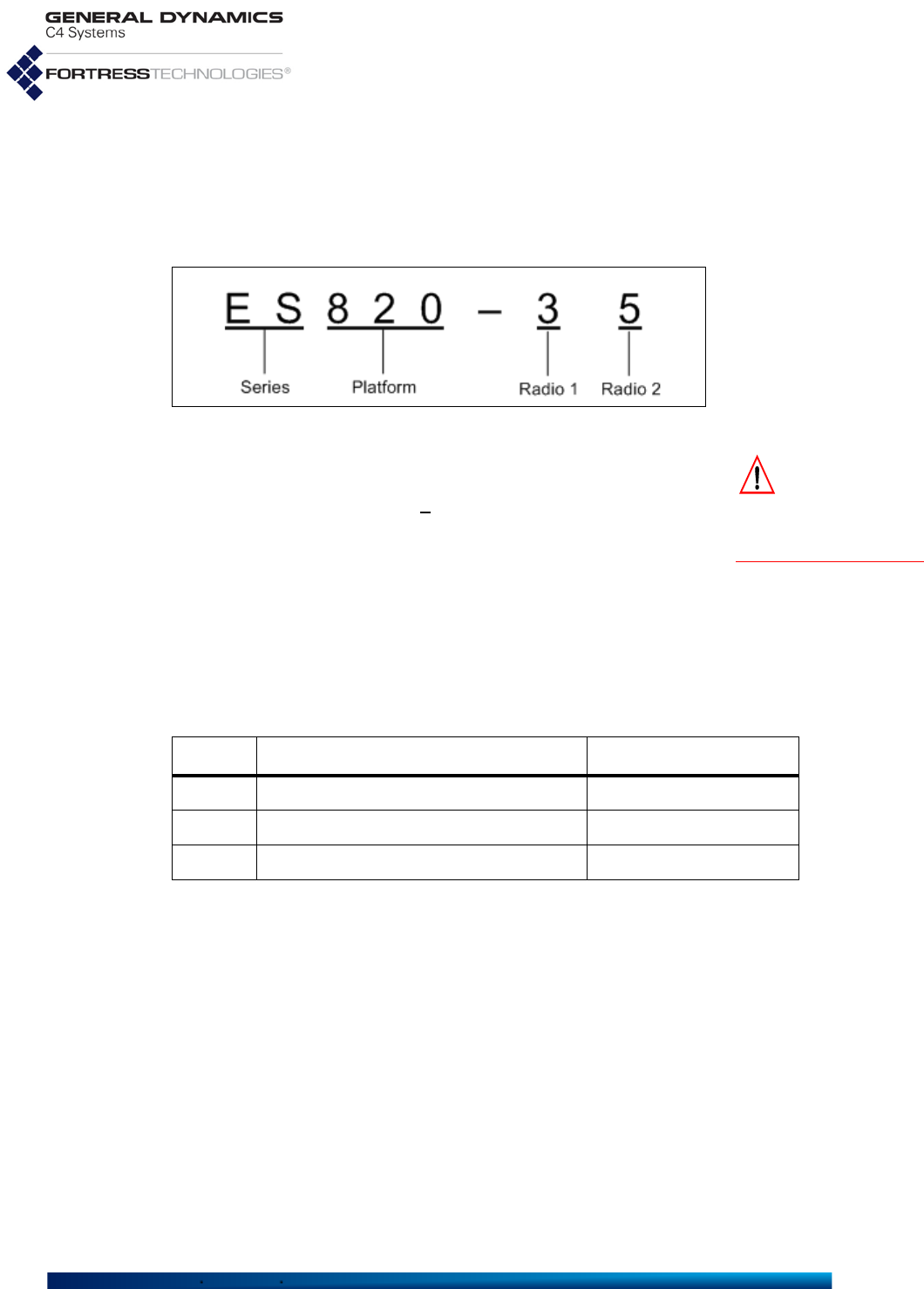
1.3.1.1 ES-Series Model Numbers
Fortress ES-series model numbers provide information about
the product platform and the number and type of radio(s) it
contains. Figure 1.1 breaks down the model number for an
ES820-35 Vehicle Mesh Point.
You can find the full model number for any ES-series Mesh
Point with the show device command:
# show device
Model: ES820-35
Version: 5.4.5.2041
SerialNumber: 109510038
Radio 1: 802.11abgn 400mW
Radio 2: 802.11an 631mW
Table 1.1 Radios and Ethernet Ports in Fortress Hardware Devices
Fortress
model # of
radios radio
label standard
equipment 4.4GHz
option GPS
Rx # Eth
ports Eth port
HW label Eth port
SW label takes
PoE serves
PoE default
encryption
ES2440
4
Radio 1 802.11a/g/n no
yes
3
Ethernet 1/WAN/
PoE Ethernet1 yes no encrypted
Radio 2–
Radio 4 802.11a/n yes
2Radio 1 802.11a/g/n no
Ethernet2 &
Ethernet 3
Ethernet2 &
Ethernet3 no no clearRadio 2 802.11a/n yes
0
n/a
ES820 2 Radio 1 802.11a/g/n no no 2 Enet1/P1 Ethernet1 no no encrypted
Radio 2 802.11a/n yes Enet2/P2 Ethernet2 no no clear
ES520 2 Radio 1 802.11a/g no no 9 WAN wan1 yes no encrypted
Radio 2 802.11a yes LAN 1–8 lan1–lan8 no yes clear
ES210 1 Radio 1 802.11a/g/n yes yes 2 Ethernet (WAN) Ethernet1 no no encrypted
Ethernet Ethernet2 no no clear
Fortress ES-Series CLI Guide: Introduction
4
DeviceIP: 192.168.4.9
Gui: On
Ssh: On
Snmp(V3): Off
Firmware version: 1.14.52
Time till reboot: not set
Figure 1.1 ES-Series Product Model Number Explication
CAUTION:
Use of
4.4 GHz radios in
the U.S. without govern-
ment approval is strictly
forbidden.
The Platform identifier for Fortress's first generation ES-series
Mesh Points is three digits, as shown in Figure 1.1. The
number “2” prefixed to the ES2440’s platform number identifies
the High-Capacity Infrastructure Mesh Point as a next
generation ES-series Fortress platform. The second-to-last
digit in the platform number represents the maximum number
of radios the platform chassis can accommodate.
The number of non-zero digits after the hyphen corresponds to
the actual number of radios installed in the Mesh Point. The
value of each digit indicates the frequency band(s) that radio
supports, as shown in Table 1.2.
Only the ES2440 supports an option for Multiple-Input Multiple-
Output ()-capable 4.4 GHz radios, indicated by the “m”
appended to these two model numbers: ES2440-34m,
ES2440-3444m (All standard equipment ES2440 radios
[802.11a/g/n and 802.11a/n] support).
A zero following the hyphen in an ES-series model number
indicates a Mesh Point with no radios installed.
1.3.1.2 Fortress Mesh Point Management
Fortress Mesh Points can be administered through either of
two native software management tools. They support SNMP
(Simple Network Management Protocol) transactions, and
each model chassis provides a small subset of basic user
controls and visual indicators.
Table 1.2 Radio Installed and Supported Frequencies
Number Radio Installed Supported Frequencies
3 802.11a/g or 802.11a/g/n 2.4 GHz or 5 GHz
4 802.11 4.4 GHz 4.4 GHz
5 802.11a or 802.11a/n 5 GHz

Fortress ES-Series CLI Guide: Introduction
5
Mesh Point GUI
The graphical user interface for Fortress Mesh Points is a
browser-based management tool that provides administration
and monitoring functions in a menu- and dialog-driven format.
It is accessed over the network via the Mesh Point’s IP
address. The Mesh Point GUI supports Microsoft® Internet
Explorer and Mozilla Firefox™. Using the Mesh Point GUI is
covered in Fortress Mesh Point Software GUI Guide.
Mesh Point CLI
The command-line interface for Fortress Mesh Points provides
administration and monitoring functions via a command line. It
is accessed over the network via a secure shell (SSH)
connection to the Mesh Point’s management interface or
through a terminal connected directly to the Mesh Point’s serial
Console port. Using the Mesh Point CLI is covered in this guide.
SNMP
Fortress Mesh Points support monitoring through version 3 of
the Simple Network Management Protocol (SNMP) Internet
standard for network management. The Fortress Management
Information Base (MIB) is included on the Mesh Point CD and
can be downloaded from the Fortress web site:
www.gdc4s.com/fortresssupport.
Chassis Indicators and Controls
Fortress Mesh Points are variously equipped with LED
indicators and chassis controls. These are covered in each
Mesh Point’s respective Hardware Guide.
1.3.2 Fortress Software and Hardware Clients
Fortress ES-series Mesh Points support standards-based
secure wireless client connections, including support for
software and hardware clients developed by Fortress.
1.4 Network Deployment Options
Fortress's FastPath Mesh link management function supports
optimal path selection and independent IPv6 mesh addressing
and DNS (Domain Name System) distribution. FastPath Mesh
networks provide higher efficiency and greater mobility than
networks using STP link management.
Although FastPath Mesh and STP networks serve the same
essential functions, the details of deploying them are not
identical. Each type of network is more fully covered in the
Fortress Mesh Point Software GUI Guide.

Fortress ES-Series CLI Guide: Mesh Point CLI and Administrative Access
7
Chapter 2
Mesh Point CLI and Administrative Access
2.1 Mesh Point CLI
NOTE: Fortress
Mesh Point fea-
tures and functions are
described in greater
detail in the Software
GUI Guide.
The Fortress Mesh Point’s command-line interface provides a
complete set of commands for managing the Fortress Mesh
Point and the network it secures, through a direct connection to
the Mesh Point’s serial console port or remotely, through the
Mesh Point’s encrypted or clear zone, using Secure Shell
(SSH).
Up and down (↑↓) arrow keys scroll through the command
history for a given CLI session, and the left and right (←→)
arrow keys navigate the current command line. If your terminal
keyboard is not equipped with arrow keys, you can use these
keyboard equivalents:
NOTE: These keys
may function dif-
ferently based on set-
tings in your terminal
emulation software.
The Tab key auto-completes partial commands sufficient to
uniquely identify the command.
Mesh Point CLI commands return
[OK]
when settings are
successfully changed and an
[Error]
message, including a
brief description of the error, when commands fail.
The clear command clears the CLI display.
Lengthy CLI output can be scrolled one screen a time, in most
cases, by appending more to the command and then paging
through the output with Enter↵ or the space bar.
Strike
Ctrl-c
to truncate scrolled output or to quit an interactive
command without making changes.
arrow/numeric keypad keyboard equivalent
up arrow (↑) Ctrl-u
down arrow (↓)Ctrl-d
left arrow (←)Ctrl-l
right arrow (→)Ctrl-r
Home Ctrl-a
End Ctrl-e
Fortress ES-Series CLI Guide: Mesh Point CLI and Administrative Access
8
2.1.1 Accessing the Mesh Point CLI via the Serial
Console Port NOTE: An RJ-45-
to-DB9 adapter
(included) is required to
connect the serial Con-
sole port to a DB9 termi-
nal connection.
1Using a null modem cable, connect the Fortress Mesh
Point’s Console port to a serial port on a computer.
2Start your serial application and, if it is not already at these
settings, configure it to use:
bits per second: 9600
data bits: 8
parity: none
stop bits: 1
hardware flow control: none
2.1.2 Accessing the Mesh Point CLI Remotely NOTE: The Mesh
Point does not
support SSH1.
When SSH (Secure Shell) is enabled, you can access the
Mesh Point CLI through an SSH2 network connection to the
Mesh Point by pointing your terminal emulation application to
the Mesh Point’s IP address.
SSH is enabled on the Fortress Mesh Point by default. Section
4.1.13 covers disabling and enabling SSH.
The Mesh Point provides users with the option to further secure
their remote administration path by allowing the SSH session
to be routed through an IPsec tunnel. First, the user needs to
configure the IPsec environment. This process is described in
Section 4.4. After this is complete, the user connects to the
Mesh Point using SSH as described in this section.
2.1.3 Logging On and Off the Mesh Point CLI NOTE: Default
passwords must
be changed when the
account is first used.
To log on to the Mesh Point CLI, enter a valid user name and
password at the Login and Password prompts.
Login: admin
Password:
<password>
ES-00148c081080-FIPS#
The first time an administrator logs on, Fortress's license
agreement displays, and you must scroll through and accept its
terms to continue. If an administrative logon banner has been
configured (Section 2.2.2), you must accept its terms to
continue.
Three administrative accounts are preconfigured on the Mesh
Point, one at each of three possible privilege levels, or defined
roles: administrator, maintenance and logviewer. Except
for the administrator-level account, which uses admin as the
Username and default password, the same strings
(maintenance and logviewer) serve as the respective
account’s Username and default password. Up to ten usable
accounts (including preconfigured accounts) are supported
(refer to Section 2.2).

Fortress ES-Series CLI Guide: Mesh Point CLI and Administrative Access
9
If the administrative account you are logging on to requires the
password to be changed, you must do so before you can
proceed and then log on again with the new password to gain
access through the account.
As shown, if the first password entry fails the complexity check,
the Mesh Point CLI automatically displays the password
requirements in effect on the Mesh Point. Administrative
password rules are global and configurable (refer to Section
2.2.1).
Login: logviewer
Password:
<password>
Please enter a new password:
<newpassword>
Please confirm the new password:
<newpassword>
The new password does not meet complexity requirements
History Depth: 0
Minimum Capital Letters: 0
Minimum Lower Case Letters: 0
Minimum Numbers: 1
Minimum Punctuation Marks: 0
Minimum Differences: 0
Minimum Length: 12
Expires: N
Expiration: 60
Expiration warning: 10
Force reset to conforming password: Y
Display previous login: disable
Inactivity Timeout: 10
Use Dictionary: disable
Allow Consecutive Characters: enable
MaxAttempts: 3
LockoutPermanent: N
LockoutDuration: 0
AccountAuthMethod: local
Account: enable
Please enter a new password:
<newpassword2>
Please confirm the new password:
<newpassword2>
ES-00148c081080-FIPS>
If the account you try to log on to has an active administrative
session in progress, the Mesh Point queries your intent:
ES-00148c081080 Login: admin
Password:
Warning! This account already has an active session. Would you like to end the other session
or cancel this login? [ endsession | cancel ] endsession
The command prompt reflects whether the role of the account
you are logged on to grants view-only privileges (maintenance
and logviewer) or full administrator-level privileges.
Accounts with view-only roles use the angle-bracket prompt:
>
.
The hash prompt:
#
indicates that you are logged on to an
administrator-level account.

Fortress ES-Series CLI Guide: Mesh Point CLI and Administrative Access
10
To log off the Mesh Point CLI, use
exit
or its synonyms:
> exit
> quit
> q
The Mesh Point CLI will time out and exit after a specified
period of inactivity (10 minutes, by default), and you must log
back in to regain access. This behavior is configurable (refer to
Section 2.2.1).
2.1.4 Accessing Mesh Point CLI Help
Use the
help
command (or its synonym,
?
) without arguments
to obtain a list of valid commands.
You can obtain a usage example—and list the command’s valid
options with their valid arguments—by entering a basic
command without options:
> show
Description: Displays system information, configuration
Usage: show [args]. Possible args:
account Displays account status and security setting
ace Displays access control entries
admin Displays Admin Users
ap Displays Access Points
association Displays current associations
audit Displays audit configuration
auth Displays authentication servers
banner Displays Welcome banner
blackout Displays blackout mode status
blocked Displays list of blocked MAC addresses
bootimage Displays boot images
bridgelinks Displays current WDS bridge links
bridging Displays bridging mode information
bss Displays Basic Service Sets
cachedauth Displays whether re-authentication is enforced
certificate Displays X.509 certificates
certificate-revocation Displays Certificate Revocation Configuration
--More--
Help output is displayed one page at a time: --More-- signals
that you can scroll additional help output, one screen at a time,
by striking any key. You can exit the --More-- scrolling
function with Ctrl-C.
Help output reflects the administrative privileges of the account
currently logged onto by displaying help for only those
commands available to the current administrator. So, for
instance, if you enter the set command without arguments
when logged on to a maintenance-level or logviewer-level
account, the Mesh Point CLI returns a command not found
message:
> set
[Error] command not found

Fortress ES-Series CLI Guide: Mesh Point CLI and Administrative Access
11
Obtain a usage example of command options for interactive
commands—and list the option’s valid switches and arguments
with a brief explanation of each—by entering
help
(or its
synonym,
?
) after the command option:
# set network ?
Description: Sets network configuration
Usage: set network [-enable <y|n>][-h hostname][-ip IP][-nm netmask][-gw defaultGW]
-enable y|n: to enable IPv4
-h hostname: name (will be shown in prompt)
-ip IP: a valid IPv4 address for the interface
-nm netmask: mask of network prefix (e.g., 255.255.255.0)
-gw defaultGW: IPv4 address of default gateway. To remove: -gw 0.0.0.0
For help with non-interactive command options, you can enter
the command-option combination without arguments:
# set accessid
Description: Sets Access ID from a HEX string
Usage: set accessid default|random|<HexString> [-confirm default|random|<HexString>]
default Sets to factory default value
random Sets to an auto-generated pseudorandom value
<HexString> Sets to a Hex string 16|32 chars (exclude optional
colons). Ex: 00:11:22:AA:BB:CC:DD:EE
2.1.5 Command Syntax
In this document, command-line text supplied by the Mesh
Point CLI is set in
plain
(non-bold, non-italic) type. All user
input is indicated by
bold
typeface. The template for the Mesh
Point CLI command syntax is shown below:
# command option <parameter> -switch req_arg1|req_arg2|req_arg3 -switch opt_arg1|opt_arg2
in which you can also note the terminology and punctuation
used here to describe command strings and parse input
elements:
Command refers to the basic operation to be performed
(ex.,
set
,
show
, etc.).
Option refers to the configuration element upon which the
command will operate (ex.,
clock
,
ap
,
clients
, etc.)
Parameter refers to a user-supplied variable, (ex.,
<
name
>
,
<
IPaddr
>
(IP address), etc.).
Arguments (
_arg
, above) are additional command inputs.
Some arguments are required by the command (
req_arg
).
Others are optional (
opt_arg
). Multiple arguments must be
separated by commas and entered without spaces.
Switch refers to the identifier, preceded by a dash (hyphen),
for the argument to follow (ex.,
-ip
,
-n
, etc.) Switches allow
permissible arguments to be entered in any combination
and order.

Fortress ES-Series CLI Guide: Mesh Point CLI and Administrative Access
12
Angle brackets: indicate variable, user-supplied inputs
(parameters and variable arguments), which are also
italicized (ex., <sharedkey>, <port1,port2,...>).
The absence of angle brackets and italics indicates literal
(or fixed) user-supplied input (ex.,
y|n
).
Pipes are placed between mutually exclusive arguments
(ex.,
y|n
).
An ellipse indicates than the argument can include more
entries of the same kind (ex., <port1,port2,...>).
A hyphen indicates an allowable range; ranges are
expressed inclusively (ex.,
1–4094
)
Many of the commands that change Mesh Point configuration
settings can be run interactively: when you enter a command
with one of its options, the parameters that can be configured
through the command display as user-navigable or
consecutively presented fields. Refer to the examples given in
the instructions below.
2.2 Administrative Accounts and Access
NOTE: The precon-
figured admin
account corresponds to
the Crypto Officer role as
defined by Federal
Information Processing
Standards (FIPS) 140-2
Security Level 2.
Up to ten usable administrative accounts can be present in the
Mesh Point’s local administrator database, used to
authenticate administrators with locally configured
administrative accounts.
View a summary of the local administrator authentication
database with show admin:
# show admin
Administration Accounts
------------- --------
Total admin users 3
Total administrators 1
Total maintainers 1
Total log viewers 1
By default, three accounts are preconfigured on the Mesh
Point, one at each of the three possible privilege levels:
administrator accounts have full privileges.
NOTE: Provided
the password is
not locked (Section
2.2.3), administrators
with maintenance or
logviewer accounts
can change their own
passwords (Section
2.2.4).
maintenance accounts have full view-only privileges and
can reset connections, reboot the Mesh Point, create
support packages, and execute ping and traceroute.
logviewer accounts have limited view-only privileges
exclusive to the system log, excluding logged configuration
information.
Only one Administrator-level account can be active on the
Mesh Point at one time. Their limited permissions allow
multiple Maintenance-level and Log Viewer-level accounts to
be active on the Mesh Point at the same time. Only one active

Fortress ES-Series CLI Guide: Mesh Point CLI and Administrative Access
13
session per administrative account is supported, regardless of
Role.
You can update administrator accounts, add new accounts and
delete any account except for the three preconfigured accounts
and (if different) the only remaining account with a Role of
administrator (refer to Section 2.2.3).
You can reconfigure the Role of any administrative account,
including the preconfigured accounts.
If you downgrade the role of the Administrator-level account
you are currently logged on through, you will be able to finish
the session with full permissions. The role change takes effect
when you next log on to the account.
At least one enabled Administrator-level account must be
present on the Mesh Point at all times. You will not be allowed
to reconfigure the Role of an Administrator-level account if it is
the only such account on the Mesh Point.
2.2.1 Global Administrator Settings
Password requirements and logon and lockout behaviors are
applied globally to locally configured administrative accounts,
as are the means by which administrators are authenticated.
View the current global administrative settings with show
account:
# show account
Security Settings
-----------------
History Depth: 0
Minimum Capital Letters: 0
Minimum Lower Case Letters: 0
Minimum Numbers: 0
Minimum Punctuation Marks: 0
Minimum Differences: 0
Minimum Length: 4
Expires: N
Expiration: 60
Expiration warning: 10
Force reset to conforming password: N
Display previous login: disable
UI Session Idle Timeout: 10
UI Failed Attempt Time Holddown: 5
Use Dictionary: disable
Allow Consecutive Characters: enable
MaxAttempts: 3
LockoutPermanent: N
LockoutDuration: 0
AccountAuthMethod: local
AccountAuthFailback: enable

Fortress ES-Series CLI Guide: Mesh Point CLI and Administrative Access
14
Failures:
---------
Password changes rejected for history: 0
Password changes rejected for complexity: 0
Password changes rejected for uniqueness: 0
2.2.1.1 Password Complexity and Expiration
History Depth specifies how many new passwords must be
created for administrator accounts before previously used
passwords can be reused. Minimums can be set for the
numbers of upper- and lowercase letters, numerals, symbols,
and differences from the last password that passwords must
contain, along with the minimum total number of characters
(Minimum Length) required.
By default, password expiration is disabled for locally
authenticated administrative accounts (Expires:
N
). When it is
enabled (Expires:
Y
), you can set the password expiration
period and configure the Mesh Point to warn administrators (at
logon) for a specified number of days in advance of expiration.
The password expiration period (Expiration) can be set from
1 to 365 days (the default is 60). The Expiration warning can
be set from 0 (zero), which disables the warning, to 365 days
(the default is 10). In addition, you can direct the Mesh Point to
expire non-conforming passwords as soon as requirements
change (
Force reset to conforming password
: Y, the default)
or allow them to persist until the next scheduled expiration (or
indefinitely, when scheduled expiration [Expires] is disabled).
Unbroken alphabetic strings within administrator passwords
can also be checked against a list of known words and
checked for numerically or alphabetically consecutive
characters (in ascending or descending order) and repeated
consecutive characters. Use Dictionary and Allow
Consecutive Characters are disabled by default.
2.2.1.2 Login, Session and Lockout Behaviors
You can configure the Mesh Point to display details of the last
log on to the account to locally authenticating administrators
when they log on:
NOTE: The idle
timeout setting for
local administrator
accounts is indepen-
dent of timeout settings
for network users and
connecting devices con-
figured on the internal
authentication server
(Section 4.5.2).
Login: admin
Password:
Last logged in at Wed Jul 16 00:54:03 2008
Last logged in from address 10.1.1.1
Last logged in from console interface
The
Display previous login
feature is disabled by default.
By default, administrative accounts time out after ten minutes
of inactivity. You can turn the feature off by specifying
0
(zero)
for
UI Session Idle Timeout
, or reconfigure the setting, in
minutes, up to
60
. UI Failed Attempt Time Holddown

Fortress ES-Series CLI Guide: Mesh Point CLI and Administrative Access
15
indicates the amount of time to wait before allowing a login
after any failed login attempt.
NOTE:
The lock-
out feature applies
exclusively to remote
logon attempts. Admin-
istrative access via a
physical connection to
the
Console
port (Section
2.1.1) is never locked.
Locally authenticating administrators are permitted a maximum
of three failed logon attempts by default, but since permanent
lockout and lockout duration are both disabled by default,
administrators who exceed the maximum are not locked out.
Maximum failed logon attempts (
MaxAttempts
) can be set from
1 to 9. A non-zero lockout duration (
LockoutDuration
) will keep
the administrator locked out for the specified number of
minutes (1 to 60). Alternatively, enabling “permanent” lockout
(
LockoutPermanent
), will keep the account locked until an
administrator logged on to an
administrator
-level account
has unlocked it:
# unlock admin -name
<adminUsername>
NOTE:
A network
failure will cause a
Mesh Point, configured
for
radius
administra-
tive authentication and
with
AccountAuth-
Failback enabled
,
to fail back to the
local
database of administra-
tive accounts, even when
the server being used is
the internal user authen-
tication server.
2.2.1.3 Authentication Method and Failback
By default, the Mesh Point authenticates administrators
through the local administrator database
(AccountAuthMethod: local)—a designated service running
on the Mesh Point itself and separate from the authentication
service that the internal RADIUS server can be configured to
provide.
Alternatively, you can configure the Mesh Point to authenticate
administrators through a standard RADIUS server
(AccountAuthMethod: radius): either a third-party RADIUS
or a Fortress RADIUS server running on a remote Mesh Point
or on the current Mesh Point.
The services available to authenticate administrators when
their authentication method is radius are those configured for
the Mesh Point, using the add auth and/or set localauth
commands (as described in Sections 4.5.1 and 4.5.2,
respectively). An account for the administrator to be
authenticated must be present on any RADIUS server(s) used
to perform the service (as described, for Fortress RADIUS
servers, in Section 4.5.3).
NOTE:
Authentica-
tion failback has
no effect when the
administrator authenti-
cation setting is local
(the default).
When administrator authentication is set to radius, Fortress
strongly advises you to leave (or restore) the Mesh Point’s
default authentication failback setting of enabled
(
AccountAuthFailback: enable
). This permits the local
administrator database to be used to authenticate
administrators when no configured external RADIUS server is
unavailable.
If administrator authentication is set to radius when
authentication failback is disabled, and the external service
becomes unavailable, all administrators will be locked out of
the Mesh Point until the RADIUS server connection has been
restored. Authentication failback is enabled by default.

Fortress ES-Series CLI Guide: Mesh Point CLI and Administrative Access
16
To use the internal Fortress RADIUS Server
to authenticate administrators:
You must execute the commands below in the order given.
1Enable the internal authentication server to provide local
authentication:
# set localauth
EnableLocalAuth[N] (Y|N to enable|disable local authentication server): y
Port[1812] (Port number to communicate):
SharedKey (Authentication key): authkey
Priority (Local server priority [0..999]):
RetryInterval (Time in seconds for retrying [1..600]):
EnableDevAuth[N] (Y|N to enable|disable Device authentication):
EnableUserAuth[N] (Y|N to enable|disable User Authentication):
DefaultDeviceState[pending] (pending|allow|deny):
DefaultMaxRetries[3] (Maximum attempts at reaching server before failover 1-30, default is 3):
DefaultIdleTimeout[30] (User idle timeout in minutes 1-720, default is 30):
DefaultSessionTimeout
(Authentication timeout in minutes, 1-200, default is 30)
:
EnableAdminAuth[N] (Y|N to enable|disable administrator authentication): y
Enable8021xAuth[N] (Y|N to enable|disable 802.1x authentication):
EnableEAP-MD5 (Y|N to enable|disable support for EAP-MD5 protocol):
EnableEAP-TLS (Y|N to enable|disable support for EAP-TLS protocol):
EnableCRLCheck[N] (Y|N to enable|disable CRL check):
EnableOcsp[N] (Y|N to enable|disable OCSP):
OcspUrl[""] (URL of OCSP responder):
EnableOcspNonce[Y] (Y|N to enable|disable OCSP nonce):
CaCertUrl[""] (URL of CA certificate or chain):
LdapSB[""] (Search base for CA certificate or chain (LDAP only)):
TLSCipherSuite (all|legacy|suite-b to set supported cipher suite for EAP-TLS):
For help with other set localauth command options,
refer to Section 4.5.2.
2Verify that authentication failback is at the default setting of
enable, and if it is disabled, enable it:
#
set account -authMethod radius -accountAuthFailback enable
For help with other set account command options, refer
to the rest of this section.
3Add an account for each administrator you want to be able
to authenticate through the internal authentication server:
# add userauth -name
<admin>
-passwd
<userpw>
-passwordConfirm
<userpw>
-adminauth administrator|maintenance|logviewer
The password must conform to the password requirements
currently in effect. -name must match that of the
administrative account for which you are configuring the
internal RADIUS account. -adminauth must correctly
identify that account’s administrative role.
For help with other add userauth command options, refer
to Section 4.5.3.

Fortress ES-Series CLI Guide: Mesh Point CLI and Administrative Access
17
To use a remote Fortress
RADIUS
Server
to authenticate administrators:
To use a RADIUS server running on another Mesh Point on the
network to authenticate administrators for the current Mesh
Point, you must configure an entry for the remote server on the
current Mesh Point (with the add auth command).
Only administrators with accounts flagged with an -adminauth
option on the remote Mesh Point’s internal RADIUS server will
be able to authenticate through this service.
To use a third-party RADIUS Server
to authenticate administrators:
To use a third-party RADIUS server for administrator
authentication, it must be configured to use Fortress’s Vendor-
Specific Attributes for Fortress-Administrative-Role and
Fortress-Password-Expired, provided in the
dictionary.fortress configuration file included on the Mesh
Point software CD and available for download at
www.gdc4s.com. Consult your RADIUS server documentation
for information on configuring the service.
An entry for the remote server must also be configured on the
current Mesh Point (with add auth).
Configure all global administrative logon, password and
authentication settings for the Mesh Point with the
set
account
command, as follows:
# set account
History Depth[0] (0-10, default is 0, maximum number of account changes to track):
Minimum Capital Letters[0] (0-5, minimum number of capitals in a password):
Minimum Lower Case Letters[0] (0-5, minimum number of lower case letters in a password):
Minimum Numbers[0] (0-5, minimum number of digits in a password):
Minimum Punctuation Marks[0] (0-5, minimum number of punctuation marks in a password):
Minimum Differences[0] (0-5, minimum number of character differences in a new password):
Minimum Length[15] (8-32, minimum length of a new password):
Expires[N] (Y|N, passwords expire after specified duration):
Expiration[60] (1-365, number of days before passwords expire):
Expiration warning[10] (0-365, number of days before warning that a new password is needed):
Force reset to conforming password[Y] (Y|N, force non conforming passwords to expire):
Display previous login[disable] (enable|disable, display information on the last session for this user):
UI Session Idle Timeout[0] ([0|60] default is 10, UI Session Idle Timeout in minutes):
UI Failed Attempt Time Holddown[5] ([0|60] default is 5, time to wait in seconds before a login will be allowed):
Use Dictionary[disable] (enable|disable, use the password dictionary):
Allow Consecutive Characters[enable] (enable|disable, allow consecutive characters in a new password):
MaxAttempts[3] (1-9, maximum number of failed attempts):
LockoutPermanent[N] (Y|N, lock this account permanently):
LockoutDuration[0] (0-60, lockout time in minutes if not locked permanently):
AccountAuthMethod[local] (local|radius, authentication method to use):
AccountAuthFailback[enable] (enable|disable, enables or disables authentication failback):

Fortress ES-Series CLI Guide: Mesh Point CLI and Administrative Access
18
NOTE:
Except for
-uiInactivity
Timeout
changes, which
take effect immediately,
changes to global
administrator settings
are applied at the next
administrator logon.
The Mesh Point CLI displays the configurable fields for set
account one at a time. Enter a new value for the field—or
leave the field blank and the setting unchanged—and strike
Enter↵, to display the next field.
Alternatively, you can execute
set
account
non-interactively
with valid switches and arguments in any order and
combination:
#
set account -historyDepth 0-10 -minCapitalLetters 0-5 -minLowerCaseLetters 0-5
-minNumbers 0-5 -minPunctuation 0-5 -minDifference 0-5 -minPasswordLength 8-32
-passwordExpires Y|N -passwordExpiration 1-365 -passwordExpirationWarning 0-365
-forceNonConfExpire Y|N -showLastLogin enable|disable -uiInactivityTimeout 0|1-60
-failedAttemptTimeout 0|1-60 -usedictionary enable|disable -allowconsecutivecharacters
enable|disable -maxtry 1-9 -lockoutperm Y|N -lockouttime 0-60 -authMethod local|radius
-accountAuthFailback enable|disable
NOTE: The pass-
word complexity
requirements estab-
lished with set
account apply equally
to administrative and
local user account pass-
words (Section 4.5.3).
The Mesh Point CLI returns [OK] when settings are
successfully changed.
You must be logged on to an
administrator
-level account to
change administrative settings (refer to Section 2.2).
2.2.2 Administrator Logon Banner
You can configure a logon banner of up to 2000 characters for
display when administrators log on to the Mesh Point.
View the currently configured WelcomeMessage with show
banner:
> show banner
If no logon banner is configured, show banner returns no text.
No welcome message is configured by default. Enter a single-
line message for display on administrator logon screens with
set banner.
# set banner -welcome
<“banner string”>
You can configure a longer banner that spans multiple lines
using the command set banner -multi.
# set banner -multi
Enter multiline text (maximum 2000 chars) and press Ctrl-C to exit
When a banner is configured, administrators must accept its
terms in order to log on.
You must be logged on to an
administrator
-level account to
change configuration settings (refer to Section 2.2).

Fortress ES-Series CLI Guide: Mesh Point CLI and Administrative Access
19
2.2.3 Individual Administrator Accounts
View details of all accounts currently in the Mesh Point’s local
administrator authentication database with show admin:
NOTE
:
Default
passwords for pre-
configured accounts are
the same as their user
names (admin, main-
tenance, logviewer)
and must be changed
the first time the
account is used.
The default configuration, as shown above, includes three
locally authenticated administrative accounts, one at each
administrative level, as summarized at the beginning of this
section (2.2).
You can configure up to seven additional accounts to the local
administrator database.
You can filter show admin output by account type:
# show admin -administrators|-maintenance|-logviewers
You can also use show admin to view the same details for a
single account:
# show admin -name <username>
Administration Accounts
-------------- --------
Total admin users 3
Total administrators 1
Total maintainers 1
Total log viewers 1
Username: admin
Full Name: admin
Description:
Role: Administrator
State: enable
Logged In: Y
Logged In Since: Mon Aug 2 22:51:18 2010 UTC
Create Time: Thu Jul 22 15:15:34 2010 UTC
Last Modified: Thu Jul 22 15:15:34 2010 UTC
Last IP: 0.0.0.0
Last Logout: Mon Aug 2 22:45:39 2010 UTC
Login Count: 18
Inactivity Logoffs: 13
Total PW Fails: 9
Number of Kickoffs: 1
Consecutive PW Fails: 1
Locked: Y
Password Locked: N
PasswordForceChange: N
GUI: Y
Console: Y
SSH: Y
#
show admin -all
Administration Accounts
-------------- --------
Total admin users 3
Total administrators 1
Total maintainers 1
Total log viewers 1
User Name Full Name Description Role State Logged In Logged In Since Login Count Inactivity Logoffs Total PW Fails Number of Kickoffs Consecutive PW Fails Locked SSH Audit
---------- ----------- ----------- ----------- ------- --------- ------------------------ ----------- ------------------ -------------- ------------------ -------------------- ------ --- --------
logviewer logviewer logviewer enable N N/A 0 0 0 0 0 N Y required
maintenance maintenance maintenance enable N N/A 0 0 0 0 0 N Y required
admin admin administrator enable Y Fri Feb 8 11:15:47 2015 3 0 1 1 0 N Y required

Fortress ES-Series CLI Guide: Mesh Point CLI and Administrative Access
20
Audit: required
2.2.3.1 Adding Administrator Accounts
Add new accounts to the local administrator database with add
admin:
# add admin
Username (User name):
<adminName>
State[enable] ([enable|disable] User state): enable|disable
Full Name[""] (Account full name): "
<full name>
"
Description[""] (Account description): "
<description of account>
"
Role[Maintenance] ([logviewer|maintenance|administrator]):
administrator|maintenance|logviewer
Password Locked[N] ([y|n] Prevent user from changing password):
NOTE: You can
exit the interac-
tive add admin com-
mand without making
changes with Ctrl-C.
PasswordForceChange[N] ([y|n] force user to change password):
Password (Password for this user):
<adminPassword>
Password Confirm (Password for this user):
<adminPassword>
GUI[enable] ([y|n] Allow user GUI access):
Console[enable] ([y|n] Allow user console access):
SSH[enable] ([y|n] Allow user CLI access):
Audit[required] ([required| prohibited | automatic ] Audit setting):
[OK]
NOTE
:
Administra-
tor
Usernames
are
case-sensitive and can
include spaces and any
of the symbols in the
set:
~!@#$%^&*()_-
+={}[]|\:;<>
,.?/ (excludes double
and single quotation
marks).
You must create a unique Username of 1 to 32 characters for
the account and configure the State, Role and Password. A
disabled account will persist in the database, but cannot be
used to log on to the Mesh Point. Account roles are described
at the beginning of this section (Section 2.2). Password
requirements for local administrative accounts are global and
configurable (refer to Section 2.2.1).
The Full Name and Description fields are optional, and the
double quotation marks are required only when fields contain
spaces or special characters (as enumerated in the NOTE to
the right).
You can enter new values for the remaining fields—or leave a
field blank and the setting unchanged by striking Enter↵, to
display the next field. These determine whether the account
password is locked and cannot be changed (
Password Locked:
Y
) or must be changed the first time the account is used
(
PasswordForceChange: Y
). Both options are disabled by
default, and if you enable
PasswordForceChange
, it will reset to N
(disabled) after the account holder has successfully changed
the password during initial logon.
By default, administrative accounts are created with permission
to access the management interface by any means: network
access to the Mesh Point GUI (gui) or CLI (cli) and terminal
access to the Mesh Point CLI through the front-panel Console
port (console). You can selectively disable access to any
interface for a given account.
Finally, remote audit logging of activity on the account can be
configured. By default, audit logging is required, which
includes all activity on the account in the audit log. A setting of
prohibited excludes all account activity from the audit log. An
Fortress ES-Series CLI Guide: Mesh Point CLI and Administrative Access
21
Audit setting of automatic causes the account to conform to
the global audit logging settings (refer to Section 4.7).
Alternatively, you can execute
add admin
non-interactively with
valid switches and arguments in any order and combination:
# add admin -name
<username>
-state enable|disable -fullname
<“Full Username”>
-desc
<“description of account”>
-role administrator|maintenance|logviewer
-passwordlock Y|N -passwordforcechange Y|N -password
<password>
-passwordconfirm
<password>
-gui enable|disable -console enable|disable -ssh enable|disable -audit
required|prohibited|automatic
The Mesh Point CLI returns [OK] when settings are
successfully changed.
NOTE:
Changes to
the account you
are currently logged
onto will take effect the
next time you log on.
2.2.3.2 Updating and Deleting Administrator Accounts
Once an administrative account has been established, you
cannot change the user name associated with it. Use the
-name switch with the update command to reconfigure the
account of the administrator you specify. The same switches
and arguments used with add admin (above) can be used to
edit other account settings:
# update admin -name
<username>
-state enable|disable -fullname
<“Full Username”>
-desc
<“description of account”>
-role administrator|maintenance|logviewer
-passwordlock Y|N -passwordforcechange Y|N -oldpassword
<oldpassword>
-password
<password>
-passwordconfirm
<password>
-gui enable|disable -console enable|disable -ssh enable|disable
-audit required|prohibited|automatic -endsession
The -endsession switch, which takes no arguments, can be
used only with update admin. It forces a current session of the
named administrative account to terminate immediately.
NOTE:
If a manu-
ally added account
is the only account cur-
rently configured with a
role
of
administra-
tor
,
del admin -all
will not delete it.
You can delete a specified administrator account (except for
the three preconfigured accounts and (if different) the only
remaining account with a role of administrator). You can
also delete all manually added administrative accounts with
the del command:
# del admin -name
<username>
|-all
You must be logged on to an
administrator
-level account to
create, update and delete administrative accounts (refer to
Section 2.2).
2.2.4 Changing Administrative Passwords
You can change any password from an administrator-level
account, including your own:
# update admin -name
<Username>
-oldpassword
<oldPassword>
-password
<newPassword>
-passwordconfirm
<newPassword>
Provided the password is not locked (refer to Section 2.2.3),
administrators with maintenance- or logviewer-level
accounts can change their own passwords using the same
command options.

Fortress ES-Series CLI Guide: Mesh Point CLI and Administrative Access
22
Password requirement for locally authenticating administrative
accounts are global and configurable (refer to Section 2.2.1).
If the you are changing the password for the account you are
currently logged on through, you will be returned to the Login
prompt: re-enter the account username and enter the new
password to re-access the Mesh Point CLI.
2.2.5 Administrative IP Address Access Control List
NOTE: Pass-
through traffic is
unaffected by enabling
the administrative IP
address ACL.
If the administrative IP address ACL is enabled, it must include
the IP addresses of any device with which the Mesh Point will
exchange administrative-level traffic. If the relevant IP
addresses are not present on the administrative IP address
ACL when the list is enabled, Mesh Point functions that depend
on administrative access will not be able to perform the
necessary operation. Mesh Point functions that require
administrative IP address access include:
NOTE: To control
pass-through traf-
fic, the user can config-
ure packet filtering,
described in Section
4.6.3.
Mesh Point administration - remote log-on to the
management interface
IGMP - incoming multicast (Internet Group Management
Protocol) traffic
NTP - incoming Network Time Protocol server packets
DHCP - incoming Dynamic Host Configuration Protocol
unicast requests
DNS - incoming Domain Name System queries
CAUTION: If, while
remotely con-
nected, you enable
administrative IP-
address access control
without first adding
your IP address, your
session will be termi-
nated and the address
blocked until it is added
to the list of permitted
addresses or the func-
tion is disabled.
IPsec - incoming IKE (Internet Key Exchange) packets from
IPsec peers
L2TP - incoming Layer 2 Tunneling Protocol traffic
RADIUS - incoming traffic from locally authenticating
administrators, users, devices, and 802.1X supplicants
OCSP - incoming Online Certificate Status Protocol traffic
CRL - incoming Certificate Revocation List traffic
ICMP and ICMPv6 - incoming Internet Control Message
Protocol packets for IPv4 (ping and traceroute) and
IPv6 (neighbor discovery messages, etc.)
By default, administrative IP address access control is
disabled: administrators can log on remotely from any
network IP address, and administrative-level traffic is freely
permitted.
# show ipacl
IP Acl enabled: No
IP Address Description
------------------------- -----------------------------------------
192.168.1.47 admin
You can configure the Mesh Point to restrict administrative
access to a limited set of allowed IP addresses by adding one

Fortress ES-Series CLI Guide: Mesh Point CLI and Administrative Access
23
or more permitted IP addresses (with optional descriptions) to
the IP address access control list and enabling the function:
# add ipacl -ip
<IPaddress>
-desc
<Description>
[OK]
# set ipacl -enable y
[OK]
You can add additional IP addresses to the permitted list at any
time.
You can delete a specified IP address or all IP addresses on
the list:
# del ipacl -ip
<IPaddress>|all
You must be logged on to an
administrator
-level account to
change configuration settings (refer to Section 2.2).
2.2.6 SNMP Settings NOTE: SNMP
authentication is
always directed to the
local authentication
server. This is the
behavior even if
RADIUS authentication
is enabled.
The Fortress Mesh Point can be configured for monitoring
through Simple Network Management Protocol (SNMP)
version 3. Fortress Management Information Bases (MIBs) for
the Mesh Point are included on the Mesh Point CD-ROM and
can be downloaded from www.gdc4s.com/fortresssupport.
When SNMP v3 support is enabled, the SNMP v3 user
(FSGSnmpAdmin) access to the Mesh Point is authenticated via
the SHA-1 message hash algorithm as defined in IETF RFC1
2574, User-based Security Model (USM) for version 3 of the
Simple Network Management Protocol (SNMPv3), using the
specified authentication passphrase. SNMP v3 privacy is
secured via the Advanced Encryption Standard with a 128-bit
key (AES-128), using the specified privacy passphrase.
SNMP v3 is disabled on the Mesh Point by default.
View the current SNMP configuration with show snmp:
> show snmp
[SNMP Configuration]
EnableV3SNMP: Y
Contact:
<contact>
Description:
<description>
Location:
<location>
EnableTrap: Y
EngineID:
<engineID>
[SNMP Trap]
[SNMP Statistics]
Total Packets In: 0
Total Packets Out: 0
----------
1. Internet Engineering Task Force Request for Comments
Fortress ES-Series CLI Guide: Mesh Point CLI and Administrative Access
24
Audit Status: required
SNMP is disabled on the Mesh Point by default.
To configure SNMP:
Configure the Mesh Point’s SNMP settings interactively with
set snmp:
# set snmp
EnableV3SNMP[N] (Y|N to enable|disable Version 3 SNMP): y
Contact[""] (Name of contact person):
<admin@domain.com>
Description["Fortress Security Controller"] (System description):
Location[""] (Name of location):
<locationID>
EnableTrap[Y] (Y|N to enable|disable trap):
PrivacyPassphrase (Privacy passphrase string):
<PrivPassphrase>
PrivacyPassphraseConfirm (Confirm privacy passphrase string):
<PrivPassphrase>
AuthPassphrase (Authentication passphrase string):
<AuthPassphrase>
AuthPassphraseConfirm (Confirm authentication passphrase string):
<AuthPassphrase>
ConfiguredEngineID[""] (5 to 32 character SNMP EngineID for this device):
NOTE: The SNMP
v3 username is
FSGSnmpAdmin and
cannot be changed.
In addition to enabling or disabling SNMP v3, you can enter a
contact E-mail address to serve as the SNMP Contact,
provide a new Description of the Mesh Point (Fortress
Controller, by default) and identify the Location of the Mesh
Point. You can optionally enable/disable SNMP traps.
If you enable SNMP v3, you must also enter and confirm
SNMP v3 authentication and privacy passphrases of 15–32
alphanumeric characters (without spaces).
Alternatively, you can use the set snmp command with valid
switches and arguments to configure SNMP on the Mesh
Point:
# set snmp -enable y|n -c
<contact>
-d
<description>
-l
<location>
-trap y|n
-authpass
<AuthenticationPassphrase>
-authpassconfirm
<AuthenticationPassphrase>
-privpass
<PrivacyPassphrase>
-privpassconfirm
<PrivacyPassphrase>
-engineid
<IDstring>
-defengineid
SNMP traps are disabled (
n
), by default, and no traps will be
sent until trap destinations are added to the Mesh Point’s
SNMP configuration (below).
With -engineid, you can specify a 5–32 character string to
serve as an SNMP engine ID to uniquely identify the SNMPv3
agent on the Mesh Point. Use -defengineid by itself to clear a
configured SNMP engine ID by restoring the default ID (unique
per Mesh Point).
To configure SNMP traps
When SNMP traps are configured, the SNMP daemon running
on the Mesh Point detects certain system events and sends
notice of their occurrence to a server running an SNMP
management application, the network management system
(NMS), or trap destination.

Fortress ES-Series CLI Guide: Mesh Point CLI and Administrative Access
25
Use the add and del (delete) commands to configure SNMP
traps, as follows:
NOTE: Fortress’s
MIB is available
for download from:
www.gdc4s.com.
# add snmptrap -ip <
nmsIPaddr
> -c “comment for display”
configures Fortress Mesh Point SNMP traps to be sent to the
SNMP management application on the server at the specified
network address and, optionally, appends a comment to be
displayed with the trap.
SNMP traps are collected and forwarded only when SNMP is
enabled (refer to Section 2.2.6).
To edit an SNMP trap entry, use the update snmptrap
command:
# update snmptrap -ip
<IPaddress>
-c
<newComment>
# del snmptrap -ip
<IPaddress>
|-all
configures the Fortress Mesh Point to stop sending SNMP
traps to the computer at the specified network address or to all
configured SNMP trap addresses.
You must be logged on to an
administrator
-level account to
configure SNMP on the Mesh Point (refer to Section 2.2).

Fortress ES-Series CLI Guide: Networking and Radio Configuration
27
Chapter 3
Networking and Radio Configuration
CAUTION: All
Mesh Points in a
mesh network must run
the same software ver-
sion.
3.1 Network Interfaces
Multiple Mesh Points can be connected through their wired
and/or wireless interfaces to form fixed or mobile tactical mesh
networks and to bridge or extend the reach and availability of
conventional hierarchical networks.
NOTE:
Incoming
IGMP (Internet
Group Management
Protocol) and Multicast
Listener Discovery
(MLD) multicast traffic
requires administrative
access. If the adminis-
trative IP address ACL
(disabled by default) is
enabled, it must include
the relevant IP
addresses. See Section
2.2.5 for more detail.
Traffic is also affected
by the per-interface
packet filters. If config-
ured, per-interface
packet filters must
include filters to permit
IGMP and MLD traffic
to and from the FMP.
See Section 4.6.3 for
more detail.
Different models of Fortress Mesh Point chassis feature
varying numbers of user-configurable Ethernet ports. Fortress
Mesh Points can be additionally equipped with one to four
independent internal radios supporting various capabilities
defined in the IEEE (Institute of Electrical and Electronics
Engineers) 802.11-2007 standard, or with no radios.
On each radio internal to a Mesh Point, up to four independent
wireless interfaces, or Basic Service Sets (BSSs), can be
configured. The maximum number of bridging BSSs supported
on any Mesh Point is eight, even on a four-radio ES2440. The
single-radio ES210 can support of a maximum of four BSSs
without regard to their function.
Alternatively, an ES210 Mesh Point can be dedicated to act as
a wireless client by configuring a single station (STA) interface
on its single internal radio.
Compare your Mesh Point’s model number to Table 3.1 on
page 38 to determine the number of Ethernet ports with which
the Mesh Point you are configuring is equipped and the
number and type(s) of radio(s) installed in it.
Fortress Mesh Point radios can connect to the radios of remote
Fortress Mesh Points to form mesh networks and, on separate
BSSs, serve as access points (APs) or access interfaces to
connect compatibly configured wireless devices to a wireless
LAN (WLAN) or to an FP Mesh access network.
On Mesh Points with more than one radio, the higher power
radio(s) dedicated to the higher frequency band (5 GHz,
standard equipment, or 4.4 GHz) will generally be the better
choice for network bridging (or backhaul) links. In Mesh Points
with two radios (ES520, ES820 and dual radio ES2440s),

Fortress ES-Series CLI Guide: Networking and Radio Configuration
28
these are Radio 2. In a four-radio ES2440, Radio 2, Radio 3
and Radio 4 are all in this category.
In Fortress Mesh Points equipped with any number of radios,
the standard-equipment Radio 1 is a dual-band 802.11a/g (or
802.11a/g/n) radio. Radio 1’s 802.11g capability typically
indicates its use to provide wireless access to devices within
range.
You can configure the Mesh Point's network interfaces to meet
various deployment and security requirements. Ethernet port
configuration is covered in Section 3.9. Creating and
configuring radio interfaces are described in Section 3.3 and
Section 3.4.
3.2 Network Bridging
Each Mesh Point can maintain simultaneous network links with
up to 100 other Mesh Points, so that up to 101 directly linked
Fortress Mesh Points can be present on a given network. Many
more Mesh Points can belong to a more widely deployed mesh
network encompassing nodes linked indirectly through other
nodes.
Networked radios must:
use the same radio frequency band (Section 3.4)
be set to the same channel (Section 3.4)
The BSSs that comprise the network must:
be enabled for bridging (Section 3.4.9)
be configured with the same SSID (Section 3.4.9)
By default, the Mesh Point can manage bridging links and route
network traffic using Fortress’s FastPath Mesh (FP Mesh)
tactical mobile networking. Alternatively, Spanning Tree
Protocol (STP) can be used for mesh link management.
However, STP is being deprecated in this release and will no
longer be a configurable option in subsequent releases.
Fortress strongly recommends using FP Mesh.
Both protocols enable the deployment of self-forming, self-
healing secure networks, and both prevent bridging loops while
providing path redundancy.
STP prevents network loops by selectively shutting down some
mesh network links.
FastPath Mesh maintains the availability of every mesh
connection and additionally provides optimal path routing of
network traffic, along with independent IPv6 mesh addressing
and DNS (Domain Name System) distribution functions to
support the FP Mesh network and user controls to configure
and tune it.

Fortress ES-Series CLI Guide: Networking and Radio Configuration
29
On certain model Mesh Points (ES820-35, ES2440-35,
ES2440-3555, ES2440-3444 and ES2440-3444m), FastPath
Mesh also permits multiple internal radios to be combined into
a single virtual FastPath Mesh bridging radio using a common
channel (refer to Section 3.3.5 for more detail).
Supported FastPath Mesh and STP network topologies are
illustrated and described in detail in the Introduction to the
Fortress Mesh Point Software GUI Guide.
You must be logged on to an administrator-level account to
change configuration settings (refer to Section 2.2).
3.2.1 Bridging Configuration
CAUTION: In order
to prevent bridg-
ing loops (multiple OSI
[open systems intercon-
nection] layer 2 paths to
the same device), you
must use -mode stp or
-mode mesh on net-
worked Mesh Points.
The Mesh Point uses FastPath Mesh bridging by default. STP
is available if enabled on the Mesh Point. View the current
bridging configuration with show bridging. The output varies
based on the type of bridging that is enabled. With FastPath
Mesh enabled, the show bridging output shows the subnet
ID and zone (encrypted or clear), as well as the Mobility
Factor, Cost Parameters (described below) and Configured
values.
> show bridging
mesh: enabled
subnetId: 0x8895
zone: encrypted
stp: disabled
Mobility Factor: 10
Cost Parameters:
'a' Cost Value: 1
'b' Cost Value: 1
Configured values:
mode: mesh
subnetId: 0x8895
zone: encrypted
With STP enabled, the show bridging output shows the
bridge priority and Mesh Point name, as well as the Mobility
Factor and Cost Parameters (described below) and
Configured values.
> show bridging
mesh: disabled
stp: enabled
priority: 49152
name: br0
Mobility Factor: 10
Cost Parameters:
'a' Cost Value: 1
'b' Cost Value: 1
Configured values:
mode: stp

Fortress ES-Series CLI Guide: Networking and Radio Configuration
30
If you are certain that connected Mesh Points are physically
configured so that no possibility exists of a bridging loop
forming, you can disable bridging link management by setting
the bridging mode to off.
# set bridging -mode off
You must be logged on to an administrator-level account to
change configuration settings (refer to Section 2.2).
3.2.2 FastPath Mesh Bridging NOTE: When
VLANs are used
in FP Mesh bridging
deployments, all Core
interfaces must be con-
figured as VLAN trunk
ports (refer to Section
3.9).
Nodes on a FastPath Mesh network are of two basic types:
FastPath Mesh Point (FPMP) - a Fortress Mesh Point with
FastPath Mesh enabled
Non-Mesh Point (NMP) - any node that is not an FPMP
FP Mesh nodes can connect over their Ethernet ports or radio
BSSs. An FP Mesh interface must be configured for the type of
connection it provides:
NOTE:
An ES210 in
STA (wireless cli-
ent) mode (Section
3.4.11) does not support
FP Mesh bridging, but
can function, like other
wireless devices, as an
NMP.
FPMPs connect to other FPMPs only on
Core
interfaces.
NMPs connect to FPMPs only on Access interfaces
A given interface can be of only one type. Each interface on a
FastPath Mesh Point can therefore be used either to connect
NMPs to the network or to bridge to other FPMPs in the
network, but a given interface cannot serve both functions at
once.
You can enable FP Mesh bridging with set bridging:
# set bridging -mode mesh
NOTE: After
changing the
bridging mode, you
must reboot the Mesh
Point.
You can also use set bridging or add mesh to configure the
rest of the settings for FP Mesh bridging, described below.
FastPath Mesh Subnet ID and ULA
When FP Mesh is enabled, a Unique Local IPv6 Unicast
Address (a.k.a. unique local address, or ULA), as defined in
RFC-4193, is generated for the Mesh Point, in the format:
| 7 bits |1| 40 bits | 16 bits | 64 bits |
+--------+-+------------+-----------+----------------------------+
| Prefix |L| Global ID | Subnet ID | Interface ID |
+--------+-+------------+-----------+----------------------------+
Prefix - FC00::/7 identifies the address as a Local IPv6
unicast address
L - 1 indicates that the prefix is locally assigned.
Global ID - pseudo-randomly allocated 40-bit global
identifier used to create a globally unique prefix
Subnet ID - 16-bit subnet identifier
Interface ID - 64-bit Interface ID

Fortress ES-Series CLI Guide: Networking and Radio Configuration
31
The ULA is not configurable. You can use set bridging to
enter a specific 16-bit hexadecimal subnet identifier. The
default is 0x8895.
# set bridging -mode mesh -s
<subnetIdInHex>
FastPath Mesh Zone
Use the -zone parameter to indicate whether FP Mesh network
traffic will pass in the
clear
zone or the
encrypted
zone:
# set bridging -mode mesh -zone clear|encrypted
Placing the network in the
encrypted
zone globally enables
end-to-end Fortress’s Mobile Security Protocol (MSP) for the
FP Mesh network.
The Mesh Point Core interfaces used to form the network must
be configured to reside in the same
-zone
as the FP Mesh
network overall (refer to Section 3.9).
You must be logged on to an administrator-level account to
change configuration settings (refer to Section 2.2).
Cost parameters
CAUTION: The
default cost equa-
tion values are normally
optimal for FP Mesh. Ill-
considered changes can
easily affect network
behavior adversely.
You can rebalance how the FP Mesh network computes the
throughput and latency costs of available data paths by
specifying new values for a and/or b in the FP Mesh cost
equation:
cost = a *(1/CLS) + b*(Q/CLS) + U
...in which:
CLS - (Current Link Speed) is the time-averaged link
speed, as measured in bits per second.
Q - is the time-averaged current queue depth, as measured
in bits.
U - is the user defined per-interface cost offset, which
allows you to configure one link to be more costly than
another. Any non-negative integer between 0 (zero) and
4,294,967,295 can be defined (for configuration
information, refer to Section 3.4.9.11 for wireless and
Section 3.9 for Ethernet interface controls).
a and b - are user defined constants, corresponding to
throughput and latency, respectively. Any non-negative
integer between 0 (zero) and 65,535 can be defined. The
default for each is 1.
Define new throughput and latency values with
set bridging -cost-parameters -a and -b, where the
aValue
is the throughput cost weighting factor and the
bValue
is
the latency cost weighting factor. As a rule, a higher
aValue
improves overall throughput, while a higher
bValue
, reduces
latency.

Fortress ES-Series CLI Guide: Networking and Radio Configuration
32
# set bridging -cost-parameters -a
<aValue>
-b
<bValue>
3.2.2.1 Multicast Snooping
When the bridging mode is configured to be mesh, the Mesh
Point automatically snoops IGMP and MLD multicast protocols
in order to provide a better multicast experience for the Non-
Mesh Points (NMPs) it supports. The Mesh Point may also be
configured to subscribe to a multicast group on behalf of an
NMP. This is useful in cases where the NMP does not use
IGMP or MLD.
If VLANs are enabled on the FastPath Mesh Point (refer to
Section 3.11), you must associate each multicast group
subscription with the VLAN used for multicast traffic. To do this,
you must subscribe by specifying the appropriate VLAN ID, in
addition to the Mesh Access interface for the stream. If a VLAN
ID of 0 is specified, the multicast group subscription will be
applied when VLANs are disabled.
Observe the multicast groups to which the MP is currently
subscribed (whether learned or configured) with show:
> show mesh -multicast-groups
VLAN ID: 1, MAC Address: 33:33:00:00:00:fb
IP Address: FF02:0:0:0:0:0:0:FB
Interface: Ethernet1, vifIndex:3
Listener(Learned)
VLAN ID: 1, MAC Address: 33:33:00:00:49:49
IP Address: Not Available
Interface: eth0, vifIndex:6
Talker(Learned)
VLAN ID: 1, MAC Address: 33:33:ff:30:d7:c0
IP Address: FF02:0:0:0:0:1:FF30:D7C0
Interface: eth0, vifIndex:6
Listener(Learned)
NOTE: Only wire-
less BSSs config-
ured as Mesh Access
interfaces can be used
for multicast group sub-
scription. Do not specify
a Mesh Core interface.
To subscribe to a multicast group, use the add mesh
command. Identify the FP Mesh interface (-interface) by
specifying the wired Interface name or wireless BSS name for
the stream and specifying the multicast address for the group
by MAC or IP address. FPMPs can subscribe as multicast
listeners, talkers or both. If VLANs are configured and enabled
on the FPMP, enter a VLAN ID for the multicast group:
# add mesh -multicast-group -ip
<IpAddress>
|-mac
<MacAddress>
-interface
<InterfaceName>
|-bss
<BssName>
-vlan
<vlanID>
-mode listener|talker|both
You can force the MP to leave a configured multicast group
with the del mesh command:
# del mesh -multicast-group -ip <
IpAddress
>|-mac <
MacAddress
> -interface <
InterfaceName
>|
-bss <
BssName
>
Fortress ES-Series CLI Guide: Networking and Radio Configuration
33
You can change the multicast group subscriptions with the
update mesh command:
# update mesh -multicast-group -ip
<IpAddress>
|-mac
<MacAddress>
-interface
<InterfaceName>
|-bss
<BssName>
-vlan
<vlanID>
-mode listener|talker|both
You must be logged on to an administrator-level account to
change configuration settings (refer to Section 2.2).
NOTE: The For-
tress Mesh Rout-
ing Protocol auto-
matically calculates the
neighbor cost based on
the quality of the link.
Overriding a neighbor
cost injudiciously can
cause disruption to the
entire mesh network.
Do not configure neigh-
bor cost overrides
unless you are working
with Fortress technical
support to troubleshoot
a problem.
3.2.2.2 Configuring Neighbor Cost Overrides
The cost of reaching a neighbor node (another Mesh Point
directly linked to the current MP) on an FP Mesh network is the
cost associated with the Mesh Core interface used to reach the
node. You can override the interface cost for a particular
neighbor by specifying a fixed cost for that node, with -
nbrcost cost, followed by an integer between 1 and
4,294,967,295. The higher the cost value, the less likely the
neighbor will be used to route network traffic.
Alternatively, you can configure the interface, with -nbrcost
maxreach, to be used to reach the specified neighbor node only
as a last resort, if no other path is available, or to never be
used, with -nbrcost unreach.
# add mesh -nbrcost cost
<1..4294967295>
|maxreach|unreach
-mac
<MacAddress>
|-ip
<IpAddress>
|-name
<NodeName>
-interface
<InterfaceName>
|-bss
<BssName>
NOTE: A node is
assumed to have
only one IPv6 unique
local address. If differ-
ent costs are configured
for the same neighbor
by more than one IPv6
address, applied cost is
unpredictable.
Specify a given neighbor’s cost override value by MAC address
(-mac), IP address (-ip), or node name (-name). Specify an
Ethernet -interface or wireless -bss by the name associated
with it.
You can update the cost override with the update mesh
command:
# update mesh -nbrcost cost
<1..4294967295>
|maxreach|unreach
-mac
<MacAddress>
|-ip
<IpAddress>
|-name
<NodeName>
-interface
<InterfaceName>
|-bss
<BssName>
Remove a neighbor cost override for a specific MAC address,
IP address, or node name; for a specific Interface name or BSS
name; or use -all to remove all the cost overrides with the del
command:
# del mesh -nbrcost {-mac <
MacAddress
>|-ip <
IpAddress
>|-name
<
NodeName
>}|{-interface <
InterfaceName
>|-bss <
BssName
>}|-all
You must be logged on to an administrator-level account to
change configuration settings (refer to Section 2.2).
3.2.3 Fine-tuning FastPath Mesh Network
Performance
The Mesh Point CLI provides set mesh commands for fine-
tuning the network performance of the FastPath Mesh network.
Available network performance settings include:

Fortress ES-Series CLI Guide: Networking and Radio Configuration
34
Multicast transmit mode
Packet interval
Transmit control
Clamping of multicast video
Mesh routing reactivity
Packet time to live value
Frame processor mode
3.2.3.1 Selecting the FastPath Mesh Multicast Transmit Mode NOTE: Do not
change the Multi-
cast Transmit Mode
unless you are working
with Fortress technical
support to troubleshoot
a problem.
The multicast transmit mode determines how multicast packets
are transmitted over radio interfaces. Specify the multicast
transmit mode with the set command:
# set mesh -multicastmode auto|reliable|efficient
When set to
auto
, the multicast mode is determined
automatically. When there is more than one neighbor with an
interested listener behind it, packets are transmitted in
efficient
mode. Otherwise,
reliable
mode is used.
Auto
is
the default multicast mode.
When the multicast mode is
reliable
, multicast packets are
transmitted reliably (that is, multicast packets are transmitted
with the reliability associated with the transmission of 802.11
unicast frames). Each multicast packet is duplicated over every
MRP (Mesh Radio Port) connection. The bandwidth consumed
by multicast packets in this mode is at least ‘n’ times the
bandwidth consumed in the ‘efficient’ mode, where n is the
number of MRP connections.
When multicast mode is
efficient
, multicast packets are
transmitted on a best-effort basis (that is, multicast packets are
transmitted with the reliability associated with the transmission
of 802.11 multicast frames). A single copy of each multicast
packet is placed on the air.
3.2.3.2 Setting the FastPath Mesh Packet Interval NOTE: Do not
change the Packet
Interval unless you are
working with Fortress
technical support to
troubleshoot a problem.
The FP Mesh packet interval is the time interval in milliseconds
between sending mesh routing protocol control packets. The
default is
auto
. Specify a packet interval in milliseconds with
the set mesh command:
# set mesh -packetinterval auto|<
100..4000>
In an FP Mesh network with 10 or fewer neighbors, the mesh
responds more quickly to changes with a smaller packet
interval. In an FP Mesh network with more than 20 neighbors,
small packet intervals are impractical due to performance
restrictions. An interval of 600 ms is practical for a mesh
network where a node may have as many as 39 neighbors.

Fortress ES-Series CLI Guide: Networking and Radio Configuration
35
NOTE: Do not
change the Trans-
mit Control setting
unless you are working
with Fortress technical
support to troubleshoot
a problem
3.2.3.3 Setting the FastPath Mesh Transmit Control Level
The FP Mesh transmit control setting determines the resiliency
level used for the transmission of control packets. This setting
balances the trade-off between the resiliency of the control
packet versus the air time consumed to send the routing
update.
Specify the transmit control level with the set mesh command:
# set mesh -transmitcontrol auto|aggressive|moderate|conservative|ultra-conservative
Setting the level to
aggressive
sends control packets in the
most efficient but least reliable way;
ultra-conservative
sends
control packets in the most reliable but least efficient way. The
default is
auto
.
You must be logged on to an administrator-level account to
change configuration settings (refer to Section 2.2).
3.2.3.4 Setting Multicast Video Clamping Thresholds
Multicast video is particularly challenging in a wireless
environment due the amount of data transmitted over the
shared wireless channel. A video stream can affect data
between other stations, and in turn be affected by other traffic
on the channel. In addition, video codecs are highly sensitive to
packet loss, which is common with multicast traffic due to the
lack of delivery retries. Even a .5–1% loss of packets can
render an MPG2 video unwatchable.
If the Mesh Point tries to stream video over a low-quality link
(low signal strength, or slow data rate), the video traffic can
clog the channel and use much of the bandwith, while the video
received is of no benefit.
Multicast clamping enables you to tune your network to prevent
multicast traffic from being sent over low-quality links. You can
essentially “clamp” the multicast stream when the Mesh Point
detects that the signal strength and bit rate are inadequate to
carry multicast video traffic.
Use set mesh with the -rssi and -rate options to define the
Received Signal Strength Indicator (RSSI) and bit-rate
thresholds (in dBm and Mbps, respectively) at which clamping
takes effect. Multicast clamping is disabled (off) by default.
Once enabled, the Mesh Point will stop sending multicast traffic
whenever the link quality drops below either of the specified
thresholds. When the link quality improves by 5 dBm beyond
the lower limits, the node will resume sending IPv4 multicast
traffic.
# set mesh -rssi
<dBmValue>
-rate <MbpsValue>
You can supply threshold values for both -rssi and -rate or
for only one parameter.

Fortress ES-Series CLI Guide: Networking and Radio Configuration
36
To determine where to set rssi and rate limits, consider the
video stream’s bit rate, the number of streams, other traffic,
and so on. For example, Fortress recommends an RSSI floor
of -80 dBm and bit-rate floor of 12 Mbps for a single, 3-Mbps
video stream sent to a cluster of four receivers.
# set mesh –rssi -
80
–rate
12
It is not necessary to continually change clamping mode values
if RSSI is near the set limit. The value set by –rssi is subject
to dampening in cases where the link’s RSSI changes quickly.
Clamping will be activated if the RSSI goes below the value set
by –rssi, and the node will not resume transmitting unless the
RSSI climbs by 5dBm. This provides a buffer so that the
system does not act too quickly on nominal changes, and
increases tolerance to rapid changes.
Multicast clamping applies only to IPv4 multicast addresses
that are not treated as broadcast, per RFC 4541.
Multicast addresses that follow the format X.0.0.Y or
X.128.0.Y, where X is in the range 224–239 (inclusive), and Y
is in the range 1–255 (inclusive), are treated as broadcast, and
therefore are not affected by multicast clamping. For example,
the IPv4 address 224.0.0.1 would not be affected by this
setting. Unaffected addresses can be assigned to low bit-rate
multicast traffic, such as text, to ensure that such traffic
continues to flow even while the higher bit-rate video is being
clamped.
3.2.3.5 Setting Mesh Routing Reactivity
FastPath Mesh network deployments must balance the stability
of the network against its reactivity to changes in network
topology. Reactivity permits the network to quickly detect and
adjust to topology changes with minimal network traffic
disruption. Stability allows the network to filter out unnecessary
topology changes to provide optimized throughput.
Three levels of reactivity can be configured on the Mesh Point.
# set mesh -reactivity least|medium|most
The least reactivity is appropriate for stationary FastPath
Mesh network and for large deployments of 30 or more nodes.
A mobile deployment should use the most reactive setting (the
default). The medium setting offers a compromise between
stability and reactivity.
3.2.3.6 Setting Mesh Packet Time To Live
In a highly-interconnected FastPath Mesh network deployment,
it is possible to have many different routing paths of
approximately equal preference between any two nodes. In this
situation, mesh’s fast routing changes may result in a

Fortress ES-Series CLI Guide: Networking and Radio Configuration
37
temporary transient routing loop. In those special deployments,
the protocol can suppress the loop more quickly if the Mesh
Time To Live (TTL) is set. The default for the TTL is four hops,
which is optimal for a large full-connected mesh and
acceptable for many other deployments.
In contrast, if the Mesh network deployment is a chain of hops
with no alternate routing paths, change the setting to be the
number of hops in the longest optimal routing path, plus 2.
To disable TTL checking, set the TTL to off or 0.
Specify the TTL setting with the set mesh command:
# set mesh -ttl off|0-15
3.2.3.7 Viewing Current Mesh Performance Parameters
View current mesh performance parameters with show:
# show mesh
Mesh is enabled
RFC 4193 ULA: FD00:0:8895:8895:214:8CFF:FE2A:1C00
Subnet Id: 0x8895
Mesh Transmit Control: auto
Mesh Reactivity: most
Mesh Time to Live: 4
Mesh Multicast RSSI clamp: -80 dBm
Mesh Multicast rate clamp: 12 Mbps
Mesh Multicast Mode: auto
Mesh Control Packet Interval: auto
3.2.3.8 Frame Processor Parameters
The Frame Processor mode should always be set to
responsive
(the default) when FastPath Mesh is enabled. This
setting should only be changed under the direction of Fortress
technical support personnel.
Establish frame processor parameters with set fp -mode.
# set fp -mode responsive|performance
View current frame processor mode settings with show fp:
# show fp
Mode: responsive
3.2.4 STP Bridging NOTE:
STP
Bridg-
ing Mode is
incompatible with the
Mesh Point’s VLAN
function (see Section
3.11).
STP bridging is being deprecated in this release and will
no longer be a configurable option in subsequent
releases. Fortress therefore recommends using FastPath
Mesh, which is the default setting.
When STP is used for link management, the Fortress Mesh
Point can connect to other Fortress Mesh Points to form mesh
networks and, on separate BSSs, simultaneously serve as
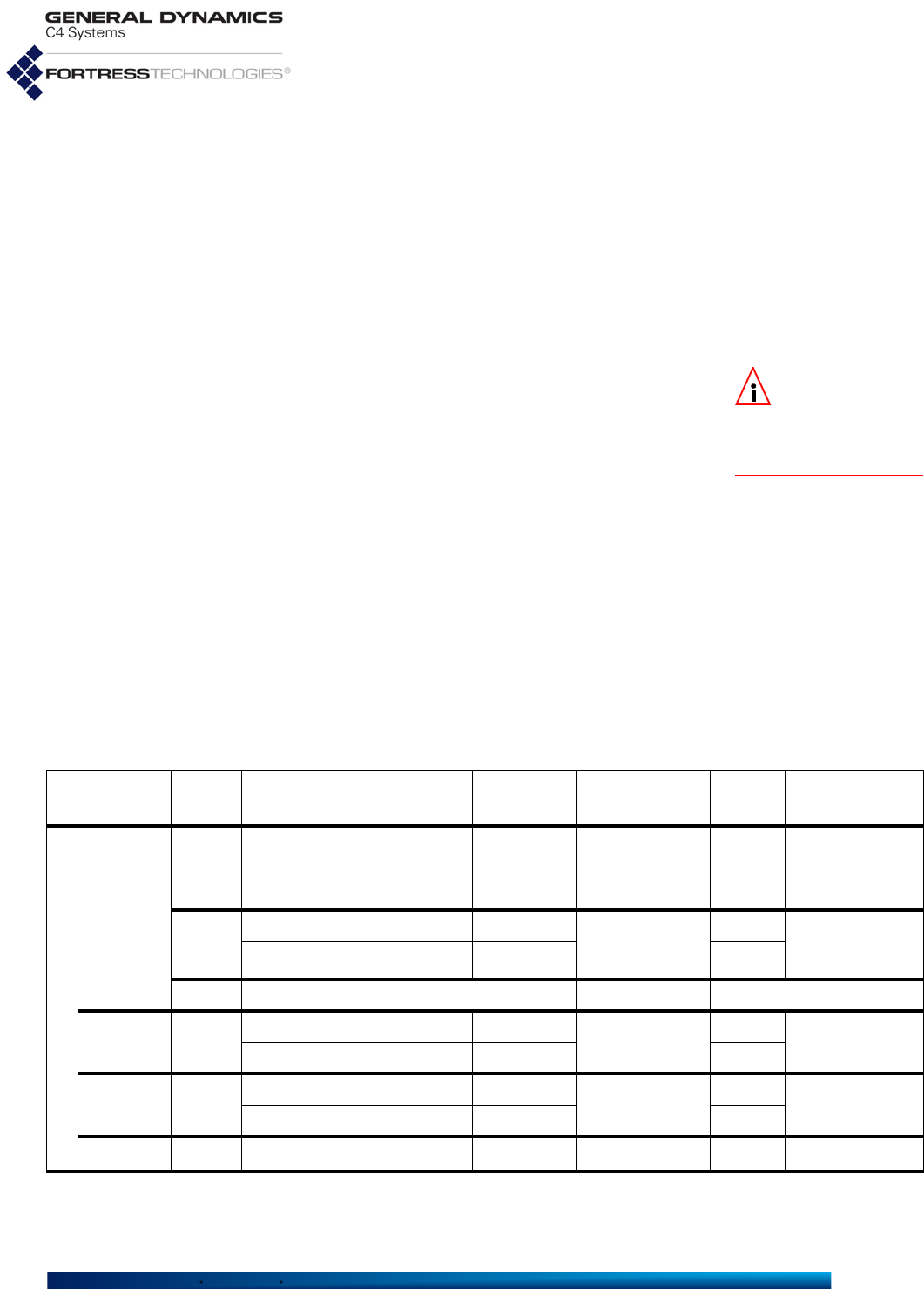
Fortress ES-Series CLI Guide: Networking and Radio Configuration
38
access points (APs) to connect compatibly configured wireless
devices to a wireless LAN (WLAN).
FastPath Mesh
is the default bridging mode.
In addition to enabling/disabling STP with the -mode switch,
you can use -p to set the priority number at which the Mesh
Point will be used as the root switch in the STP configuration.
The Mesh Point with the lowest priority number on the network
serves as STP root. The default is
49152
. Configure Bridging
with set bridging:
NOTE: After
changing the
bridging mode, you
must reboot the Mesh
Point.
# set bridging -mode stp -p 0...65535
You must be logged on to an administrator-level account to
change configuration settings (refer to Section 2.2).
View current STP bridging settings using the command show
stp.
# show stp
BridgeID EnableSTP BridgePriority
-------- --------- --------------
br0 1 49152
3.3 Global Radio Settings
Global settings apply to all radios internal to the Mesh Point.
Different Fortress Mesh Point models can be variously
equipped with one to four independent internal radios
supporting various 802.11 capabilities, or with no radios.
Table 3.1 Fortress Mesh Point Model Radios
series
basic
model # of
radios radio
label standard
equipment default
band standard
model # 4.4GHz
option 4.4 GHz
model #
ES
ES2440a
4
Radio 1 802.11a/g/n 802.11g
ES2440-3555
b
no ES2440-3444
b
or
ES2440-3444m
b
Radio 2–
Radio 4 802.11a/n 802.11a yes
2
Radio 1 802.11a/g/n 802.11g
ES2440-35
b
no ES2440-34
or
ES2440-34m
Radio 2 802.11a/n 802.11a yes
0n/a ES2440-0 n/a
ES820 2
Radio 1 802.11a/g/n 802.11g
ES820-35
b
no ES820-34
Radio 2 802.11a/n 802.11a yes
ES520 2
Radio 1 802.11a/g 802.11g ES520-35 no ES520-34
Radio 2 802.11a 802.11a yes
ES210 1
Radio 1 802.11a/g/n 802.11a ES210-3 yes ES210-4
a. All standard-equipment (802.11a/g/n and 802.11a/n) ES2440 radios support MIMO (
Multiple-Input Multiple-Output
);
MIMO-capable 4.4GHz radios are optional, as indicated by the final “m” in these 4.4 GHz model numbers.
(Enable MIMO through the Mesh Point CLI, as described in the CLI Guide.)

Fortress ES-Series CLI Guide: Networking and Radio Configuration
39
Compare your Mesh Point’s model number to Table 3.1 above
to determine the number of and type of radio(s) with which the
Mesh Point you are configuring is equipped. Use show device
(refer to Section 6.1) to view the model number and other
system information.
NOTE: ES210 Mesh
Point BSS and STA
functions are mutually
exclusive.
Each radio installed in a Fortress Mesh Point can be configured
with up to four BSSs, which can serve either as bridging
interfaces networked with other Fortress Mesh Points or as
access interfaces for connecting wireless client devices. A
maximum total of eight bridging-enabled BSSs can be present
on multi-radio Mesh Points: a hardware constraint in dual radio
models, but a maximum that must be user-imposed on a four-
radio ES2440. Refer to Section 3.4.9 for details on radio BSS
configuration.
When ES820-35, ES2440-35, ES2440-3555 and ES2440-3444
model Mesh Points are enabled for FastPath Mesh bridging,
their internal radios can instead be configured, in twos or
threes (depending on the model), to use a single channel and
act as a single virtual bridging radio with improved coverage
and/or mobility.
Alternatively, an ES210 Mesh Point can be dedicated to act as
a wireless client by configuring a single station (STA) interface
on its single internal radio. Refer to Section 3.4.11 for details on
radio STA configuration.
3.3.1 Country Code and Regulatory Authorities
The available and default Country Code depends on the area
license in effect on the Mesh Point:
United States (US)
- is the only available Country Code
when the Mesh Point is licensed to operate in the United
States, the default.
Public Safety (PS)
- is the only available Country Code
when the Mesh Point is licensed to operate in the 4.9 GHz
frequency band, reserved for official public safety
transmission in the United States.
Argentina (AR)
- is the default Country Code when the
Mesh Point is licensed to operate outside of the United
States: a World area license permits you to select from a
list of 123 countries, excluding the
United States
and
Public Safety
Country Codes described above.
Refer to Section 5.6 for information on obtaining a new area
license and installing it on the Mesh Point.
To allocate bandwidth and prevent interference, radio
transmission is a regulated activity, and different regulatory
authorities specify hardware configurations and restrict the
b. Channel Sharing, combining multiple radios in a virtual bridging radio, option available with FastPath Mesh.

Fortress ES-Series CLI Guide: Networking and Radio Configuration
40
strength of signals broadcast on particular frequencies
according to different rules.
If necessary, the Mesh Point filters options available for
individual radio settings (Section 3.4) according to the
requirements of the relevant regulatory domain as they apply to
the Mesh Point’s internal radios.
In order to comply with the requirements of the relevant
regulatory domain, the Country code must accurately identify
the country in which the Mesh Point will operate or, in the case
of the US Public Safety code, the context in which it will be
used.
The rules of the Federal Communication Commission (FCC)
regulatory domain dictate available radio settings in the 5 GHz
802.11a and the 2.4 GHz 802.11g frequency bands in the
United States.
The 4.4 GHz - 4.9 GHz frequency range is regulated by the United
States National Telecommunications and Information
Administration (NTIA). Use of 4.4 GHz radios in the U.S.
without government approval is strictly forbidden.
View the country currently specified with show country:
> show country
US
The help output for set country provides the country codes
for all countries that can be specified.
# set country
Usage: set country CountryShortName
[US]
Possible Countries:
US United States
NOTE: Changing
the Country Code
requires you to reboot
the Mesh Point (see Sec-
tion 5.2).
Establish the Mesh Point’s country of operation with set
country:
# set country
<CountryCode>
The US is specified by default.
3.3.2 Environment Setting NOTE:
Contact
your Fortress rep-
resentative about inter-
national and specialized
licensing options.
Mesh Points in the U.S. are restricted to outdoor use. The
setting is therefore fixed on outdoor on Mesh Points licensed
for U.S. operation (the default), and the set environment
command cannot be used.
You can, however, view the environment setting with show
environment:
> show environment
outdoor
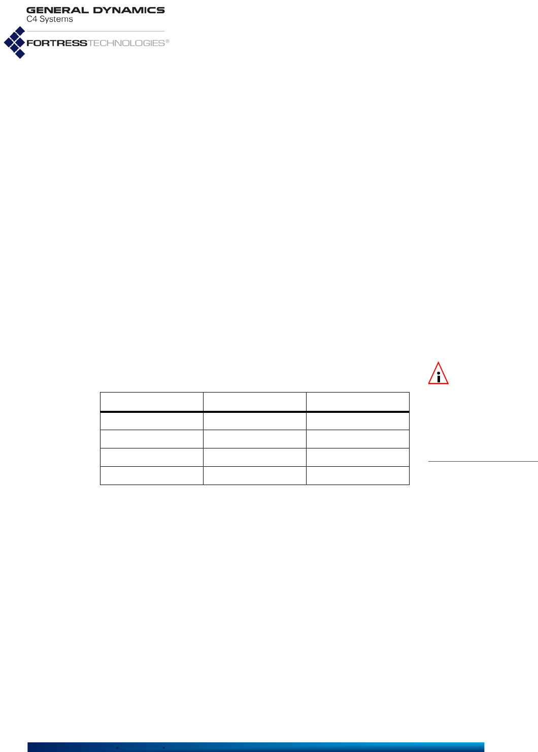
Fortress ES-Series CLI Guide: Networking and Radio Configuration
41
3.3.3 Unit of Distance Measure
Mesh Point radios are individually configured for the distance
over which they transmit and receive (refer to Section 3.4). The
unit used to measure the specified distance is itself a globally
configured setting.
View the unit of measure currently specified with show unit:
> show unit
metric
Establish the unit of measure for Mesh Point radio distance
settings with set unit:
# set unit english|metric
When
metric
is specified (the default), the Mesh Point sets
distances in kilometers. When
english
is specified, the Mesh
Point sets distances in miles.
3.3.4 Radio Frequency Kill
On all radio-equipped platforms other than the ES820, the RF
kill function simply turns the radio(s) installed in the Mesh Point
off (
Enabled
) and on (
Disabled
).
NOTE:
Refer to the
ES820 Vehicle Mesh
Point Hardware Guide
,
Specifications for the
37-Pin Input/Output Con-
nector
, for more informa-
tion on the
RF Kill
toggle
switch.
On the ES820, Kill All RF behavior depends upon the physical
state of its RF Kill latch/toggle switch:
On ES820 Mesh Points, the current state of the RF Kill
hardware toggle is displayed (view-only) in the Mesh Point
GUI, beside the Kill All RF setting.
The default RF kill setting on all platforms is
Disabled
, in which
state the Mesh Point receives and transmits radio frequency
signals normally. Use set rfkill to enable or disable the RF
kill function.
# set rfkill disable|enable
View the current RF Kill setting with show rfkill.
# show rfkill
Disabled
You can also enable/disable RF kill through Fortress Mesh
Point chassis controls (refer to the Fortress Hardware Guide
for the Mesh Point you are configuring).
Kill All RF
SW Setting RF Kill HW Toggle RF Killed?
Disabled Disabled/Off No
Disabled Enabled/On Yes
Enabled Disabled/Off Yes
Enabled Enabled/On Yes
Fortress ES-Series CLI Guide: Networking and Radio Configuration
42
3.3.5 Channel Sharing NOTE:
The channel
sharing
function
is absent from CLI
set
options and
show radio
output on Mesh Points
that do not support it.
On ES820-35, ES2440-35, ES2440-3555, ES2440-3444 and
ES2440-3444m model Mesh Points that are enabled for
FastPath Mesh bridging (described in Section 3.2.2), you can
combine certain of their internal radios into a single virtual
bridging radio by enabling channel sharing.
In certain deployments, such virtual channel-sharing radios can
provide superior coverage and/or mobility for network bridging
links.
NOTE: Changing
sharing requires
you to reboot the Mesh
Point (see Section 5.2).
Channel sharing is disabled by default.
When channel sharing is enabled on dual radio Mesh Points
that support the function (the ES820-35 and ES2440-35),
Radio 1 and Radio 2 are combined to form a single virtual
radio, configured with a single set radio command set. When
channel sharing is enabled on four-radio Mesh Points that
support it (the ES2440-3555 and ES2440-3444), Radio 2,
Radio 3, and Radio 4 are combined in this way.
Because a virtual radio created through channel sharing is
configured through a single set radio command set, identical
configuration parameters are applied simultaneously to all of
the radios included in the virtual radio.
NOTE: A virtual
radio created
through channel shar-
ing can be used only for
network bridging.
Like their common radio settings, the single bridging BSSs
configured on radios combined through channel sharing must
be identically configured. To facilitate this, when you add a
new BSS to the virtual radio, the BSS is replicated
automatically on each of the radios that comprise the channel-
sharing virtual radio. Any subsequent changes to this virtual
combined BSS will likewise be extended to the configurations
of each actual BSS that comprises it.
Channel sharing is limited to Unlicensed National Information
Infrastructure (UNII)-3 channels in the 5 GHz-band: 149–165,
when not on a 4.4 GHz radio.
View the current sharing setting with show sharing.
# show sharing
Disabled
The default channel sharing setting on all platforms is
Disabled
, in which state Mesh Point radios function
independently. Use set sharing to enable or disable channel
sharing on Mesh Point radios.
# set sharing disable|enable
As command output informs you, you must reboot the Mesh
Point in order for a change to channel sharing to take effect.
# set sharing enabled
[OK] This change will not take effect until the system is rebooted.
# reboot

Fortress ES-Series CLI Guide: Networking and Radio Configuration
43
Confirm: Reboot device now? [Y|N] y
3.4 Individual Radio Settings
View the current settings for the Mesh Point’s radio(s) with
show radio.
Mesh Points with more than one radio display each radio’s
configuration information separately:
> show radio
RadioName: radio1
AdminState: disable
RadioBand: 802.11g
ChannelToUse: 1
Distance: 1
NetworkType: PtMP
AntennaGain: 9
ShortPreamble: enable
BeaconInterval: 100
NoiseImmunity: disable
ChannelLock: disable
ChannelScan: enable
Reunification: enable
LonelyNode: enable
Timeout: 300
IgnoreRequest: disable
TransmitPower: auto
Oper Status: down
Chan Number: 0
Chan Frequency: 0 KHz
Chan Width: 0 MHz
Chan Max TPO: 0 dBm
Chan Max EIRP: 0 dBm
Chan TX Power: 0 dBm
RF Kill: Disabled
------------------------------------
RadioName: radio2
AdminState: disable
RadioBand: 802.11a
ChannelToUse: 149
Distance: 1
NetworkType: PtMP
AntennaGain: 9
BeaconInterval: 100
NoiseImmunity: disable
ChannelLock: disable
ChannelScan: enable
Reunification: enable
LonelyNode: enable
Timeout: 300
IgnoreRequest: disable
TransmitPower: auto
Oper Status: down
Chan Number: 0
Chan Frequency: 0 KHz
Chan Width: 0 MHz
Chan Max TPO: 0 dBm
Chan Max EIRP: 0 dBm
Chan TX Power: 0 dBm
RF Kill: Disabled

Fortress ES-Series CLI Guide: Networking and Radio Configuration
44
As described for Channel Sharing (Section 3.3.5, above),
multiple Mesh Point radios can be combined to form a single
virtual radio. The settings of radios combined in this way are
still shown separately in show radio output. The channel
sharing state of Mesh Points that support is included in show
radio output (Chan Sharing: Enabled), and radios that make
up a channel-sharing virtual radio are shown to have identical
settings.
# show radio
RadioName: radio1
AdminState: disable
RadioBand: 802.11naht40plus
ChannelToUse: 149
Distance: 1
NetworkType: PtMP
AntennaGain: 9
GuardInterval: long
BeaconInterval: 100
NoiseImmunity: disable
TransmitPower: auto
Oper Status: down
Chan Sharing: Enabled
Chan Number: 0
Chan Frequency: 0 KHz
Chan Width: 0 MHz
Chan Max TPO: 0 dBm
Chan Max EIRP: 0 dBm
Chan TX Power: 0 dBm
RF Kill: Disabled
------------------------------------
RadioName: radio2
AdminState: disable
RadioBand: 802.11naht40plus
ChannelToUse: 149
Distance: 1
NetworkType: PtMP
AntennaGain: 9
GuardInterval: long
BeaconInterval: 100
NoiseImmunity: disable
TransmitPower: auto
Oper Status: down
Chan Sharing: Enabled
Chan Number: 0
Chan Frequency: 0 KHz
Chan Width: 0 MHz
Chan Max TPO: 0 dBm
Chan Max EIRP: 0 dBm
Chan TX Power: 0 dBm
RF Kill: Disabled
NOTE: Antenna
port labels corre-
sponds to radio num-
bering: Radio 1 uses
ANT1, and so on.
The RadioName corresponds to the Mesh Point’s front-panel
labeling. It is used to identify the interface you can configure
with set radio, as described below.
On Mesh Points with channel sharing enabled (see Section
3.3.5), the virtual combined radio settings can be displayed
(and configured) by specifying the RadioName of any of the

Fortress ES-Series CLI Guide: Networking and Radio Configuration
45
radios included in it: radio1 or radio2 on the ES820-35 and
ES2440-35; radio2, radio3 or radio4 on the ES2440-3555,
ES2440-3444 or ES2440-3444m. Configuration changes made
to any of the combined radios will be propagated to all of the
radios that make up the virtual radio.
AdminState normally displays the radio’s actual operational
state and corresponds with the configured value. Under certain
circumstances, the state of a Mesh Point radio can become
temporarily impossible to determine. In these cases,
AdminState displays Unavailable.
The conditions that can produce such an AdminState are
typically short-lived and will clear immediately. During certain
DFS events, however, or in cases where all possible channels
are excluded, an AdminState of Unavailable can persist for
more extended periods of up to 30 minutes.
Below the configured settings, show radio displays current
operating details for the radio, among them:
Chan Max TPO - the maximum transmit power output in
dBm at antenna connector, based on the operating channel
and regulatory constraints
Chan Max EIRP - the maximum Equivalent Isotropically
Radiated Power in dBm, based on the operating channel
and regulatory constraints
Chan TX Power - the peak transmit power output in dBm on
the operating channel
Configure radio settings interactively by entering the set
radio command without arguments. The Mesh Point CLI
presents one field at a time, and you can either enter a new
value for a given field or strike Enter↵ to leave the value
unchanged and go on to the next field.
The following example shows all of the settings you can
administer with set radio. The available values for each
setting may vary based on the Mesh Point you are
administering.
# set radio
RadioName (radio1 name of radio interface):
radio2
AdminState[disable] (enable|disable to set radio interface state):
RadioBand[802.11a] (802.11g|802.11nght20|802.11nght40plus|802.11nght40minus|
802.11a|802.11naht20|802.11naht40plus|802.11naht40minus to set band):
802.11naht40plus
GuardInterval[long] (any|long to set short and long, or only long HT40 guard interval
(reboot required)):
ChannelToUse[149] (channel number to use):
Distance[1] (Distance in mile or kilometer):
BeaconInterval[100] (25..1000 to set beacon interval in milliseconds):
NetworkType[PtMP] (PtMP|PtP to set network type):
AntennaGain[5] (0..50 to set antenna gain in dBi):

Fortress ES-Series CLI Guide: Networking and Radio Configuration
46
TransmitPower (auto|1..33 to set transmit power in dBm):
NoiseImmunity[disable] (enable|disable to set noise immunity):
MIMO[N] (Y|N to enable MIMO operational mode):
ForceSTBC[Y] (Y|N to force STBC transmission):
ChannelLock[disable] (enable|disable to set channel lock):
ChannelScan[enable] (enable|disable to set channel scan):
IgnoreRequest[disable] (enable|disable to set ignore channel change request):
Reunification[enable] (enable|disable to set reunification):
LonelyNode[enable] (enable|disable to set lonely node):
Timeout[300] (60..86400 to set lonely node timeout in seconds):
RadioName identifies the radio and cannot be changed.
AdminState simply turns the radio on and off.
3.4.1 Radio Band, Short Preamble, Guard Interval
NOTE: Radio2
cannot be config-
ured to use the
802.11b/g
frequency band.
RadioBand selects both the frequency band of the radio
spectrum a Mesh Point radio will use (for dual band radios) and
whether it will use the 802.11n standard for wireless
transmission/reception (for radios that support the option).
5 GHz and 2.4 GHz Options
Radios installed as Radio 1 in radio-equipped Fortress Mesh
Points (refer to Table 3.1, above) can operate in either the
5 GHz 802.11a frequency band or the 802.11g 2.4 GHz band of
the radio spectrum, according to your selection for RadioBand.
By default, a dual-band radio installed as Radio 1 in a multi-
radio Mesh Point is configured to operate in the 2.4 GHz
802.11g band. The dual-band radio installed in the ES210 is
configured to operate in the 802.11a band by default.
CAUTION:
Use of
4.4 GHz radios in
the U.S. without govern-
ment approval is strictly
forbidden.
In Mesh Points equipped with more than one radio, the
additional radio(s) can function in only a single frequency band:
the 5 GHz 802.11a band in standard-equipment radios, or the
4.4 GHz band in Mesh Points that support this option.
The virtual channel-sharing radio that can be created by
combining radios on select model Mesh Points through
channel sharing (as described in Section 3.3.5) is limited to
the 5 GHz 802.11a frequency band UNII-3 channels.
The RadioBand setting is among those subject to the relevant
regulatory domain. In some cases, in order to bring the Mesh
Point into compliance, dual-band radios could be automatically
fixed on the 802.11g band and radios fixed on the 802.11a
band could be disabled altogether. Consult your local
regulatory authority for the applicable specifications and
requirements for radio devices and transmissions.
ShortPreamble applies only to 2.4 GHz band operation:
# set radio
RadioName (name of radio interface, any of radio1|radio2): radio1
AdminState (enable|disable to set radio interface state):

Fortress ES-Series CLI Guide: Networking and Radio Configuration
47
RadioBand[802.11g](802.11b|802.11g|802.11nght20|802.11nght40plus|802.11nght40minus|
802.11a|802.11naht20|802.11naht40plus|802.11naht40minus to set band):
ShortPreamble[enable] (enable|disable to set 802.11b short preamble):
[...etc.]
The short preamble is used by virtually all wireless devices
currently being produced, so leaving the setting at its default
enabled value is recommended for most network deployments.
When ShortPreamble is disabled, connecting devices must
use the long preamble, which is still in use by some older
802.11b devices. If the WLAN must support devices that use
the long preamble, you must
disable
ShortPreamble.
802.11n Options
BSSs configured on the radio(s) installed in certain Mesh Point
models are additionally capable of 802.11n operation (refer to
Table 3.1 on page 38).
A Mesh Point radio BSS configured to use the 802.11n standard
is fully interoperable with other 802.11n network devices.
On 802.11n-capable radios, there are three possible high-
throughput (
ht
) 802.11n options for each frequency band
supported on the radio: three for the 5 GHz 802.11na band
and three for the 2.4 GHz 802.11ng band, when present:
ht20
- 802.11n - High-Throughput 20 MHz, the radio will
use only 20 MHz channel widths, while taking advantage of
the standard’s traffic handling efficiencies.
ht40plus
- High-Throughput 40 MHz plus 20 MHz, the
radio can use 40 MHz channel widths by binding the
selected 20 MHz channel to the adjacent 20 MHz channel
above it on the radio spectrum.
ht40minus
- High-Throughput 40 MHz minus 20 MHz, the
radio can use 40 MHz channel widths by binding the
selected 20 MHz channel to the adjacent 20 MHz channel
below it on the radio spectrum.
On ES2440-34m and ES2440-3444m Mesh Points, there is a
fourth high-throughput (ht) option for the 4.4 GHz band radios:
ht10
- 802.11na - High-Throughput 10 MHz, the radio will
use only 10 MHz channel widths while taking advantage of
the standard’s traffic handling efficiencies.
NOTE: Changing
the radio
guard-
interval
requires you
to reboot the Mesh Point
(see Section 5.2).
When an 802.11n HT40 band setting is specified
(802.11naht40plus, 802.11naht40minus,
802.11nght40plus, and 802.11nght40minus), you can
specify whether the radio will use only
long
guard intervals
between symbol transmissions (the default), or that the radio
can use
any
(i.e., both long and short) symbol transmission
guard intervals.

Fortress ES-Series CLI Guide: Networking and Radio Configuration
48
3.4.2 Channel Selection
The ChannelToUse setting selects the portion of the radio
spectrum the radio will to use to transmit and receive—in order
to provide wireless LAN access or to establish the initial
connections in a mesh network.
NOTE: Consult
your local regula-
tory authority for appli-
cable radio device and
transmission rules and
for DFS channel desig-
nations.
The channels available for user selection are determined by
the frequency band the radio uses, subject to the relevant
regulatory domain rules. In most regulatory domains, certain
channels in the 5 GHz frequency band are designated DFS
(Dynamic Frequency Selection) channels. DFS compliance
also restricts the channels available for user selection (and
broadcast) on 802.11a radios.
Without a Channel license installed (refer to Section 5.6),
5 GHz-band Unlicensed National Information Infrastructure
(UNII) 2 extended channels 116, 132 and 136 are also
unavailable for selection. These channels are restricted by the
FCC requirement for a 30MHz guard band around Terminal
Doppler Weather Radar (TDWR) operating within 35km (refer
to Section 3.4.8.2).
NOTE: Where
2.4GHz 802.11g
channels power levels
are restricted (e.g. the
EU countries), Fortress
radios which cannot
effectively comply will
disable the 802.11g
channels. The default in
that situation is band
802.11a and channel
100.
A dual-band radio that uses the 2.4 GHz 802.11g band by
default ((Radio 1 in all multiple-radio Mesh Points)) is set to
channel 1 by default.
The second internal radio in multiple-radio Mesh Points (the
5 GHz 802.11a Radio 2 in the standard model ES2440, ES820
and ES520) and a dual-band radio that uses 802.11a by default
(the single Radio 1 in the ES210) has a default channel setting
of:
149, when the Mesh Point is licensed for standard United
States operation (the default).
20, when the Mesh Point is licensed for United States
Public Safety operation.
C1, when the Mesh Point is equipped with 4.4 GHz band
radios.
Radio 3 and Radio 4 in an ES2440-3555 are set by default to
channels:
157 and 165, respectively, when the Mesh Point is licensed
for standard United States operation (the default).
40 and 60, respectively, when the Mesh Point is licensed for
United States Public Safety operation.
C1' and C3, respectively, when the ES2440 Mesh Point is
equipped with 4.4 GHz band radios.

Fortress ES-Series CLI Guide: Networking and Radio Configuration
49
Table 3.2 shows radio channel-to-frequency mappings for
radios using the 802.11b/g/n bands.
Table 3.3 shows radio channel-to-frequency mappings for
radios using the 802.11a/n bands.
Table 3.2 Mapping 802.11b/g/n Radio Channels to Frequencies, in MHz
Setting Center 802.11 b/g or 802.11n ht20 802.11n ht40 Plus 802.11n ht40 Minus
Low High Low High Low High
Channel 1 2412 2402 2422 2402 2442 ~ ~
Channel 2 2417 2407 2427 2407 2447 ~ ~
Channel 3 2422 2412 2432 2412 2452 ~ ~
Channel 4 2427 2417 2437 2417 2457 ~ ~
Channel 5 2432 2422 2442 2422 2462 2402 2442
Channel 6 2437 2427 2447 2427 2467 2407 2447
Channel 7 2442 2432 2452 2432 2472 2412 2452
Channel 8 2447 2437 2457 ~ ~ 2417 2457
Channel 9 2452 2442 2462 ~ ~ 2422 2462
Channel 10 2457 2447 2467 ~ ~ 2427 2467
Channel 11 2462 2452 2472 ~ ~ 2432 2472
Table 3.3 Mapping 802.11a/n Radio Channels to Frequencies, in MHz
Setting Center 802.11a or 802.11n ht20 802.11n ht40 Plus 802.11n ht40 Minus
Low High Low High Low High
Channel 52 5260 5250 5270 5250 5290 ~ ~
Channel 56 5280 5270 5290 ~ ~ 5250 5290
Channel 60 5300 5290 5310 5290 5330 ~ ~
Channel 64 5320 5310 5330 ~ ~ 5290 5330
Channel 100 5500 5490 5510 5490 5530 ~ ~
Channel 104 5520 5510 5530 ~ ~ 5490 5530
Channel 108 5540 5530 5550 5530 5570 ~ ~
Channel 112 5560 5550 5570 ~ ~ 5530 5570
Channel 116 5580 5570 5590 ~ ~ ~ ~
Channel 120 disabled due to FCC restrictions in the 5600-5650MHz band for
avoiding interference with TDWR systems (refer to Section 3.4.8)
Channel 124
Channel 128
Channel 132 5660 5650 5670 5650 5690 ~ ~
Channel 136 5680 5670 5690 ~ ~ 5650 5690
Channel 140 5700 5690 5710 ~ ~ ~ ~
Channel 149 5745 5735 5755 5735 5775 ~ ~
Channel 153 5765 5755 5775 ~ ~ 5735 5775
Channel 157 5785 5775 5795 5775 5815 ~ ~
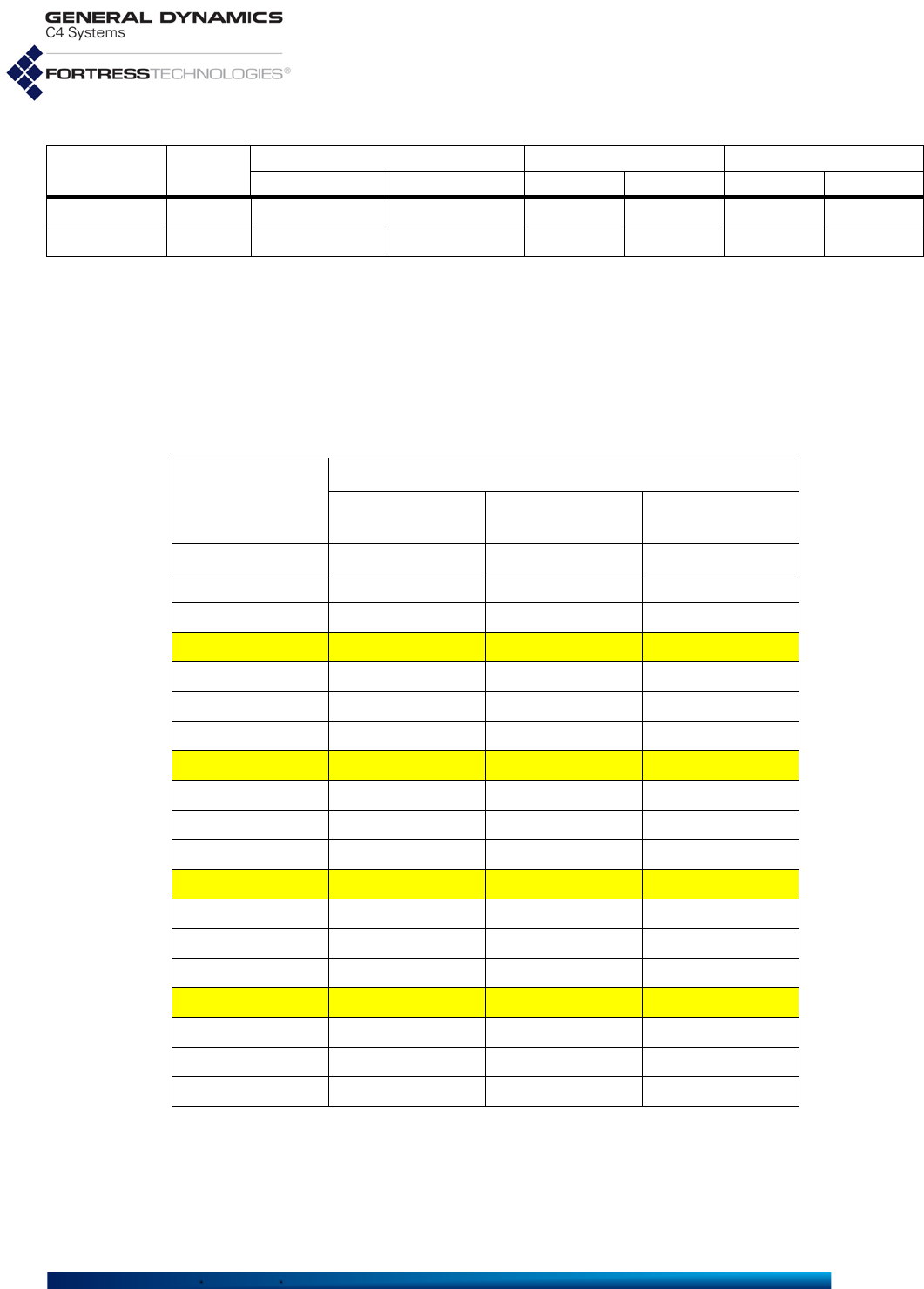
Fortress ES-Series CLI Guide: Networking and Radio Configuration
50
Table 3.4 shows the channels available for selection when the
Mesh Point is licensed for United States Public Safety
operation, with the corresponding frequency. All channels are
available to the standard model 520 5GHz 802.11a-only band
radio. Highlighted rows show the only Public Safety channels
available to other 5GHz model radios. For more information on
radio models, see Section 1.3.1 and Table 3.1.
Channel 161 5805 5795 5815 ~ ~ 5775 5815
Channel 165 5825 5815 5835 ~ ~ ~ ~
Table 3.3 Mapping 802.11a/n Radio Channels to Frequencies, in MHz
Setting Center 802.11a or 802.11n ht20 802.11n ht40 Plus 802.11n ht40 Minus
Low High Low High Low High
Table 3.4 Mapping 4.9 GHz Public Safety Radio Channels to Frequencies
Setting
Frequency
5 MHz Nominal
Channel Width 10 MHz Nominal
Channel Width 20 MHz Nominal
Channel Width
Channel 5 4942.5 ~ ~
Channel 10 ~ 4945 ~
Channel 15 4947.5 ~ ~
Channel 20 ~ ~ 4950
Channel 25 4952.5 ~ ~
Channel 30 ~ 4955 ~
Channel 35 4957.5 ~ ~
Channel 40 ~ ~ 4960
Channel 45 4962.5 ~ ~
Channel 50 ~ 4965 ~
Channel 55 4967.5 ~ ~
Channel 60 ~ ~ 4970
Channel 65 4972.5 ~ ~
Channel 70 ~ 4975 ~
Channel 75 4977.5 ~ ~
Channel 80 ~ ~ 4980
Channel 85 4982.5 ~ ~
Channel 90 ~ 4985 ~
Channel 95 4987.5 ~ ~

Fortress ES-Series CLI Guide: Networking and Radio Configuration
51
Table 3.5 shows the channels available for selection on
4.4 GHz Mesh Point radios, with their corresponding center
frequencies and nominal frequency ranges. Channels in the
shaded cells are available only on the 4.4 GHz radios installed
in the ES2440-3444m and ES2440-34m
Table 3.5 Mapping 4.4 GHz Radio Channels to Frequencies
20 MHz Nominal Channel Width 40 MHz Nominal Channel Width
Channel
Setting Center
Frequency Nominal
Range Channel
Setting Center
Frequency Nominal
Range
C1 4410 4400-4420 A1 4420 4400-4440
C2 4430 4420-4440
C3 4450 4440-4460 A2 4460 4440-4480
C4 4470 4460-4480
C5 4490 4480-4500 A3 4500 4480-4520
C6 4510 4500-4520
C7 4530 4520-4540 A4 4540 4520-4560
C8 4550 4540-4560
C9 4570 4560-4580 A5 4580 4560-4600
C10 4590 4580-4600
C11 4610 4600-4620 A6 4620 4600-4640
C12 4630 4620-4640
C13 4650 4640-4660 A7 4660 4640-4680
C14 4670 4660-4680
C15 4690 4680-4700 A1’ 4720 4700-4740
C1’ 4710 4700-4720
C2’ 4730 4720-4740 A2’ 4760 4740-4780
C3’ 4750 4740-4760
C4’ 4770 4760-4780 A3’ 4800 4780-4820
C5’ 4790 4780-4800
C6’ 4810 4800-4820

Fortress ES-Series CLI Guide: Networking and Radio Configuration
52
The virtual radio that can be created by combining radios on
select model Mesh Points through channel sharing (as
described in Section 3.3.5) is limited to 5 GHz-band UNII-3
channels: 149 (the default) –165 (when the virtual radio is not
comprised of 4.4 GHz radios).
3.4.3 Distance, Beacon Interval, Noise Immunity
When the radio is used for bridging, set Distance to the
greatest unbridged distance between neighbor network nodes.
The unit used, kilometers by default, is determined by the set
unit control (Section 3.3.3). The default of 1 is appropriate for
radios used to provide network access to local wireless
devices.
Table 3.6 Mapping 4.4 GHz Radio Channels to Frequencies
10 MHz Nominal Channel Width
Channel
Setting Center
Frequency Nominal
Range Channel
Setting Center
Frequency Nominal
Range
D1 4405 4400-4410 D22 4615 4610-4620
D2 4415 4410-4420 D23 4625 4620-4630
D3 4425 4420-4430 D24 4635 4630-4640
D4 4435 4430-4440 D25 4645 46404650
D5 4445 4440-4450 D26 4655 4650-4660
D6 4455 4450-4460 D27 4665 4660-4670
D7 4465 4460-4470 D28 4675 4670-4680
D8 4475 4470-4490 D29 4685 4680-4690
D9 4485 4480-4490 D30 4695 4690-4700
D10 4495 4490-4500 D1’ 4705 4700-4710
D11 4505 4500-4510 D2’ 4715 4710-4720
D12 4515 4510-4520 D3’ 4725 4720-4730
D13 4525 4520-4530 D4’ 4735 4730-4740
D14 4535 4530-4540 D5’ 4745 4740-4750
D15 4545 4540-4550 D6’ 4755 4750-4760
D16 4555 4550-4560 D7’ 4765 4760-4770
D17 4565 4560-4570 D8’ 4775 4770-4780
D18 4575 4570-4580 D9’ 4785 4780-4790
D19 4585 4580-4590 D10’ 4795 4790-4800
D20 4595 4590-4600 D11’ 4805 4800-4810
D21 4605 4600-4610 D12’ 4815 4810-4820
Fortress ES-Series CLI Guide: Networking and Radio Configuration
53
CAUTION:
Radios
using DFS chan-
nels (Section 3.4.8)
must
use the default
100
ms
BeaconInterval
.
The Fortress BeaconInterval default of 100 milliseconds is
optimal for almost all network deployments and recommended
for bridging operation. Configure the interval in milliseconds
between 25 and 1000—only when necessary (as required by
an unusual network deployment) and only on radios using non-
DFS channels.
The NoiseImmunity setting allows 802.11a radios to
compensate for unusual local interference by aggressively
lowering the receive threshold for connected nodes. Noise
Immunity is
disabled
by default, and Fortress recommends
retaining this default unless operating conditions require a
change.
3.4.4 Network Type, Antenna Gain, Tx Power NOTE: Antenna
port labels corre-
sponds to radio num-
bering: Radio 1 uses
ANT1, and so on.
NetworkType and AntennaGain values are used to calculate
allowable
TransmitPower
values and are therefore also subject
to regulatory requirements. Consult applicable rules for the
regulatory domain in which the radio is operating to determine
permitted settings.
The TransmitPower setting can automatically determine the
appropriate power setting based on country of operation and
other factors using
auto
(the default), or you can manually set
the transmit power to a value between 1-33 dBm. In order to
comply with relevant rules and regulations, you must configure
the Mesh Point with values that accurately reflect its hardware
configuration and conform to the applicable TransmitPower
limit for the Mesh Point’s current regulatory domain. Consult
your local regulatory authority for applicable specifications and
requirements for radio devices and transmissions.
The Mesh Point permits you to select TransmitPower settings
that exceed those allowed by your current configuration, but a
warning will signal the error. Do not exceed the TxPower limit
for the Mesh Point’s current configuration and regulatory
domain.
3.4.5 MIMO CAUTION: It is
important to install
both antennas for a
MIMO-enabled radio, or
the radio will not func-
tion.
Only the ES2440 can be equipped with radios that support
Multiple-Input Multiple-Output (MIMO) wireless operation. Both
standard-equipment 802.11a/g/n and 802.11a/n radios support
MIMO, and MIMO support is optionally available in ES2440s
equipped with 4.4 GHz radios.
You can quickly determine whether the 4.4 GHz radios installed
in the ES2440 support MIMO by observing the number of
antenna ports per radio on the chassis back panel. MIMO-
capable radios are equipped with two antenna ports. MIMO
support is additionally indicated by the final "m" in these
platform’s full model numbers: ES2440-34m, ES2440-3444m.
Fortress ES-Series CLI Guide: Networking and Radio Configuration
54
Other Fortress platform models, with or without 4.4 GHz-radio
options, do not.
NOTE:
The
MIMO
function
is absent
from CLI
set radio
options and
show radio
output on Mesh Points
that do not support it.
MIMO can be enabled only when the radio is configured to use
one of the 802.11n frequency Band options. MIMO is disabled
by default on all radios that support it.
In order to take advantage of MIMO, both radios forming a
given link must be configured for it. In a mixed network
environment, MIMO-enabled radios will negotiate the best
mutually supported communication with Single-Input Single-
Output (SISO) radios.
Use the interactive set radio command to configure MIMO on
any radio that supports the function. Or use set radio with the
-mimo switch with Y and N arguments.
#
set radio -mimo Y|N
The command will fail if the radio is not configured to use one
of the 802.11n -band options.
3.4.6 STBC
Space-Time Block Coding (STBC) is a technique that helps
improve error rates and reliability in a system that is
experiencing poor transmission performance. This
improvement is accomplished by transmitting a stream over
multiple antennas which provides the receiver with multiple
copies of the same data stream. The redundancy in the
transmission increases the range and provides the receiver
with a better chance to receive the complete signal.
NOTE:
The STBC
function is absent
from CLI
set radio
options and
show radio
output on Mesh Points
that are not capable of
transmitting STBC
encoded signals.
The ES2440-35, -3555, -3444, -34, -3444m, and -34m are
capable of transmitting STBC encoded signals when MIMO is
enabled. When the transmission quality drops below MCS-8
and MIMO is enabled, the radio will transmit STBC encoded
signals. The ES2440-35, -3555, -3444, -34, -3444m and -34m
are also capable of receiving STBC encoded signals.
The ES820-35 and -34 are capable of receiving STBC
encoded signals, but are not capable of transmitting STBC
encoded signals. Transmission of STBC encoded signals is
automatic below MCS-8 on any radio that supports the
function. To force transmitting STBC encoded signals at all
times (even when the radio would normally use a rate higher
than MCS-7), use the interactive set radio command with the
-forcestbc switch with Y argument. This favors reliability or
range over throughput. The default for -forcestbc is N.
#
set radio -forcestbc Y|N

Fortress ES-Series CLI Guide: Networking and Radio Configuration
55
NOTE: Settings for
ChannelLock
and ChannelScan do
not affect the channel
scanning behavior of an
configured STA inter-
face, which must chan-
nel scan to find an AP
with which to associate.
3.4.7 Channel Lock and Other Channel Selection
Features
When ChannelLock is set to
enable
(default is
disable
) and at
least one BSS is configured, the radio will not switch from the
currently configured channel, regardless of settings or activity
that would ordinarily trigger a channel switch. The Mesh Point
ignores WDS-related channel scanning and remote WDS peer
channel change requests. Radar events that occur while on a
DFS channel cause the radio to be disabled, rather than to
select an alternate channel.
NOTE: When
enabled, Chan-
nel Lock takes prece-
dence over any other
channel selection func-
tion, except for channel
scanning on configured
STA interfaces. Settings
for the remaining chan-
nel selection functions
do not appear in show
radio output.
When ChannelLock is
enabled
, the Channel Scanning,
Reunification, and Lonely Node features are
disabled
, and the
Ignore Remote Channel Change Request feature is
enabled
.
You cannot change these settings, and these parameters do
not appear in the output for show radio.
When ChannelScan is set to
enable
(the default), WDS-related
channel scanning occurs under any of the following conditions:
a WDS-enabled BSS exists and the Mesh Point is booting
a WDS BSS is administratively disabled, then re-enabled
the radio is administratively disabled and re-enabled
the lonely node feature is enabled
When Channel Scanning is
disabled
(explicitly, or via Channel
Lock), Reunification and Lonely Node are also disabled.
The IgnoreRequest setting of
enable
causes the Mesh Point
to drop remote channel-change requests. When set to
disable
(the default), remote channel change requests from compatible
peers are processed and if the channel isn’t excluded, the
Mesh Point changes to the requested channel. If the channel is
excluded, a channel change request for an alternate channel is
sent. When Channel Lock is enabled, IgnoreRequest is also
enabled.
When Reunification is
enabled
(default), during WDS-related
channel scanning, a remote channel change request is sent to
unselected channels in order to unify disjoint networks. For
example, during WDS-related channel scanning, a Mesh Point
with a WDS-enabled BSS with SSID “bravo” discovers a
compatible “bravo” network on channels 149 and 165. Based
on channel precedence, the Mesh Point chooses one of these
two frequencies for operation. It then sends a remote channel
change request to the unselected channel so that all Mesh
Points can operate on a common channel. When Channel Lock
is enabled or Channel Scanning is disabled, Reunification is
disabled.
When the LonelyNode setting is
enable
(default), the Mesh
Point scans periodically to select an alternate channel with
compatible peers. The Lonely Node Timeout setting

Fortress ES-Series CLI Guide: Networking and Radio Configuration
56
determines the scan interval, between
60–86400
seconds (the
default is
300
). Lonely Node operates under the following
conditions:
Channel Lock is disabled
Channel Scanning is enabled
A WDS BSS is enabled
No FP Mesh peer connections exist on the bridging radio
The same settings are output interactively regardless of the
specified radio. The possible values for each setting vary
based on the features supported by the Mesh Point you are
administering.
Alternatively, you can use the set radio command with valid
switches and arguments to change the radio settings:
# set radio -name radio1|radio2 -adminstate enable|disable
-band 802.11g|802.11nght20|802.11nght40plus|802.11nght40minus|802.11a|802.11naht20|
802.11naht40plus|802.11naht40minus -guardinterval any|long -shortpreamble enable|disable
-channel
<channel#>
-distance 1–50 -beaconint 25–1000 -nettype PtMP|PtP -gain 0–50
-txpower auto|1–33 -noiseimmunity enable|disable -mimo Y|N -forcestbc Y|N-lock enable|disable
-scan enable|disable -reunification enable|disable -lonelynode enable|disable
-lonelynodetimeout 60–86400 -ignorereq enable|disable
The sample output for the show radio command (at the
beginning of this section) shows the default radio settings.
You must be logged on to an
administrator
-level account to
change configuration settings (refer to Section 2.2).
3.4.8 DFS, TDWR, and Channel Exclusion
Channels in the 5 GHz 801.11a frequency band can be
excluded from selection by several means and for various
reasons.
3.4.8.1 Dynamic Frequency Selection NOTE: Radar
events occurring
while on a DFS channel
while ChannelLock is
enabled cause the radio
to be disabled, rather
than to select an alter-
nate channel. (See Sec-
tion 3.4.7.)
Most regulatory domains, including the Mesh Point’s default
FCC domain, require that certain channels in the 5 GHz
801.11a frequency band operate as DFS (Dynamic Frequency
Selection) channels.
DFS is a radar (radio detection and ranging) avoidance
protocol. Devices transmitting on a DFS channel must detect
approaching radar on the channel, vacate the channel within
10 seconds of doing so, and stay off the channel for a minimum
of 30 minutes thereafter.
Radios using the 2.4 GHz 802.11g frequency band or the
4.4 GHz band are not subject to DFS.

Fortress ES-Series CLI Guide: Networking and Radio Configuration
57
3.4.8.2 Licensed TDWR Channels NOTE: Without a
license, channels
116, 132 and 136 cannot
be entered in the
ChannelToUse set-
ting, or entered using
add xchannel.
In order to satisfy the FCC requirement for a 30 MHz guard
band around Terminal Doppler Weather Radar (TDWR)
operating within 35 km, UNII 2 extended channels 116, 132
and 136 are available for selection only when a Channel
license is installed on the Mesh Point (refer to Section 5.6).
When a Channel license is installed, you can satisfy the TDWR
requirement using static channel exclusions (refer to Section
3.4.8.3, below).
3.4.8.3 Channel Exclusion
A channel can be excluded from use by the Mesh Point’s
radios in the following ways:
NOTE:
Channel
sharing
among
multiple internal radios
can be enabled on select
model Mesh Points in
certain deployments.
Refer to Section 3.3.5.
It has been specified for exclusion (see below).
For DFS channels, radar was detected on the channel,
automatically excluding it from use for 30 minutes.
Another of the Mesh Point’s internal radios is using the
channel.
For bridging radios, the channel was learned remotely from
another node in the network.
NOTE: Remotely
learned channel
exclusions age out of the
excluded list after the
remote Mesh Point
stops propagating the
exclusion.
If a Channel license is installed (refer to Section 5.6), and the
Mesh Point is operating in the vicinity of Terminal Doppler
Weather Radar, the FCC requires you to exclude channels
within 30 MHz of TDWR frequencies (refer Section 3.4.8.2).
The currently excluded channels you can view with show
xchannel are sorted according to cause, where both the DFS
and other-radio channel exclusions are listed under Local
Exclusion List Entries.
Mesh Points with more than one radio display channel
exclusion information for each radio separately, or you can
specify the radio to view using -radio:
#
show xchannel -radio <radioName>
RadioName: radio1
Static Exclusion List Entries (Admin)
Channel Band Freq (KHz)
------- ------- ----------
None
Local Exclusion List Entries
Channel Band Freq (KHz) Reason Timeout (mins)
------- ------- ---------- ------------------ --------------
None
Remote Exclusion List Entries (Seen on WDS Peer)
Channel Band Freq (KHz)
------- ------- ----------
None
Fortress ES-Series CLI Guide: Networking and Radio Configuration
58
NOTE: You must
specify the ES210
Mesh Point’s radio by
name: radio1.
Add channels to the Static Exclusion List with add
xchannel:
# add xchannel -radio radio1
|radio2
-channel <#>
Delete channels from the exclusion list with del xchannel:
# del xchannel -radio radio1
|radio2
-channel <#> -all
You must be logged on to an administrator-level account to
change configuration settings (refer to Section 2.2).
3.4.9 Radio BSS Settings NOTE: An ES210
Mesh Point can
alternatively support a
single wireless client
STA Interface. (Refer to
Section 3.4.11.)
View the current settings for configured Basic Service Sets
(BSSs) with show bss:
> show bss
No BSS are configured for radio1
No BSS are configured for radio2
By default there are no BSSs configured on any radio.
You can configure up to four BSSs on an individual Mesh Point
radio with the add bss command. A maximum total of eight
bridging-enabled BSSs can be present on multi-radio Mesh
Points: a hardware constraint in dual radio models, but a
maximum that must be user-imposed on a four-radio ES2440.
A virtual radio created through channel sharing, as described in
Section 3.3.5, can support only a single bridging BSS.
3.4.9.1 BSS Radio, BSS Name and SSID NOTE: An SSID
cannot be shared
across multiple BSSs on
the same Mesh Point,
unless channel
sharing
is enabled (refer to Sec-
tion 3.3.5).
The minimum parameters required to create a new BSS are to
identify the radio (-radio) on which it will be created, name the
BSS (-name) and provide an SSID of up to 32 characters or
enter
random
with the -ssid switch to generate a random 16-
character SSID.
Certain interface names and prefixes, such as
aux
and
sta_
,
are reserved for internal use. If the BSSName you enter is
reserved, the Mesh Point CLI will return an error requiring you
to modify your entry.
# add bss -radio radio1 -name bss1.1 -ssid random
[OK]
The above example creates a BSS with these default settings:
# show bss
RadioName: radio1
Name: bss1.1
Ssid: <randomly generated ssid>
EnableWDS: N
AdminState: enable
AdvertiseSsid: Y
DropBroadcastProbeReq: N
IdleTimeout: 5
Only11g: N

Fortress ES-Series CLI Guide: Networking and Radio Configuration
59
WMM: enable
FragThreshold: off
RtsThreshold: off
DtimPeriod: 1
VlanId: 1
SwitchingMode: access
VlanAllowAll: Y
VlanActiveTable: <none>
Zone: encrypted
UcostOffset: 0
Description:
802.1X/11i Security: none
RateMode: auto
MaxRate: 54
MinRate: 1
McastRate: 1
BssId: 00:14:8c:08:10:91
Except for the final line of output (BssId, which displays the
BSS’s MAC address), if you specify only the radio, each of the
settings shown above can be configured interactively with add
bss:
# add bss -radio radio1
BssName (string for identity): bss1.2
Ssid ('random'(randomly generate)|string(32 chars max)): ssid1.2
EnableWds[N] (Y|N to allow peer-to-peer connection): y
MinimumRSS (-95..0 to set minimum receive signal strength when WDS is enabled):
AdminState (enable|disable to set BSS administrative state):
AdvertiseSsid (Y|N to advertise or hide SSID in Beacon frame): n
DropBroadcastProbeReq (Y|N to drop or respond to broadcast Probe Request frame sent with no SSID):
StaIdleTimeout[5] (timeout in minutes before an idle STA is disassociated):
Only11g (Y|N to support only 802.11g):
RateMode (auto|fixed to set bit-rate adaptation mode):
MaxRate (1|2|5.5|11|6|9|12|18|24|36|48|54 to set maximum transmission rate in Mbps):
MinRate (1|2|5.5|11|6|9|12|18|24|36|48|54 to set minimum transmission rate in Mbps):
WMM (enable|disable to set Wi-Fi Multimedia (WMM) support):
FragThreshold (off|256..2345 to set maximum fragment size):
RtsThreshold (off|1..2345 to set minimum packet size for RTS/CTS handshake):
DtimPeriod (DTIM period in beacon intervals):
VlanId (1..4094 to assign the interface to the corresponding VLAN):
SwitchingMode (trunk|access to set VLAN mode):
AllowAll (Y|N to allow all VLANs in trunk interface):
Table (list of active VLAN IDs when allow all is disabled):
Zone (clear|encrypted (default is encrypted)):
UCostOffset (0..4294967295 to set user-defined offset used to compute virtual interface cost):
McastRate (1|2|5.5|11|6|9|12|18|24|36|48|54 to set multicast transmission rate in Mbps):6
EnhancedMcast (Y|N to set enhanced multicast):
BeaconEncrypt (enable|disable to set WDS Beacon Management frame encryption):
WdsMtu (wifi|ether to set mtu size for WDS links):
Description (string of description):
802.1X/11i Security (none|wpa|wpapsk|wpa2|wpa2psk|wpa2mixed|wpa2mixedpsk):
[OK]

Fortress ES-Series CLI Guide: Networking and Radio Configuration
60
3.4.9.2 WDS Bridging or AP Infrastructure Configuration NOTE: BSSs with
WDS enabled are
always in the Mesh
Point’s encrypted zone.
Enabling WDS (Wireless Distribution System) functionality
(EnableWds
y
) enables the Mesh Point radio on which the BSS
is configured for bridging: The BSS can be used to connect as
a node in a network of Mesh Points.
When the BSS is enabled for bridging, you can also set the
minimum received signal strength (MinimumRSS), that other
WDS network nodes must maintain in order to stay connected,
in decibels referenced to milliwatts from -95 to 0 (zero), with
zero disabling the function (i.e., permitting nodes to stay
connected at any RSS). The default is -80 dBm. When WDS is
disabled (EnableWds
n
), MinimumRSS does not apply.
The single BSS supported on a virtual radio created through
channel sharing (described in Section 3.3.5), is restricted to
bridging operation (EnableWds
y
).
A BSS on which WDS is disabled (EnableWds
n
) can be used
to provide infrastructure network connectivity for wireless
devices in range, enabling the radio on which the BSS is
configured as an AP (access point).
3.4.9.3 BSS State, SSID Advertising and Drop Probe Requests
AdminState allows you to take a BSS off line (
disable
it)
without deleting it from the Mesh Point configuration. Newly
added BSSs are enabled by default.
NOTE: Setting
AdvertiseSsid
to yes is not permitted
on bridging BSSs, where
enabling the function
would serve no pur-
pose and could pose a
security risk.
AdvertiseSsid gives you the option of broadcasting the SSID
(
y
, the default) or hiding it (
n
) for Access Point (AP) BSSs.
SSIDs should never be advertised for bridging BSS: You
cannot enable AdvertiseSsid when WDS is enabled
(EnableWds
y
).
Enabling DropBroadcastProbeReq causes the BSS to ignore
probe requests that do not include the BSS's currently
configured SSID. The function is
disabled
by default.
Enabling this feature reduces probe responses, which is not
appropriate for all deployments but can boost available
bandwidth under certain circumstances. Fortress recommends
that you leave the setting at its default value, except under the
direction of Technical Support.
3.4.9.4 BSS STA Idle Timeout and 802.11g-Only Settings
When the BSS is used as a network AP, you can also set an
IdleTimeout for the interface: the maximum period of time
that a connected devices’s session can remain inactive before
the Mesh Point terminates its association to the BSS. Set
StaIdleTimeout in whole minutes between
1
and
71582788
; or
specify
0
(zero) to disable the function, permitting devices
associated with the BSS to remain connected regardless of
session inactivity.
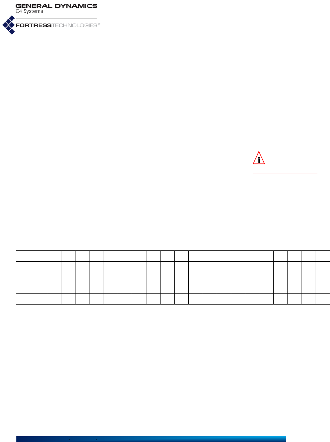
Fortress ES-Series CLI Guide: Networking and Radio Configuration
61
You can configure BSSs on Radio 1 to accept connections only
from 802.11g devices (Only11g
y
), instead of also accepting
802.11b device connections (Only11g
n
, the default).
3.4.9.5 BSS Unicast Transmission Rate Settings
When a BSS is configured to use a RateMode setting of
auto
(the default), the interface dynamically adjusts the bit rate at
which it transmits unicast data frames—throttling between the
configured MaxRate and MinRate—to provide the optimal data
rate for the connection.
At a RateMode setting of
fixed
, the BSS will use the
configured MaxRate for all unicast transmissions and ignore
the configured MinRate.
NOTE: Radio Band
settings are cov-
ered in Section 3.4.
Transmission rates are set in megabits per second (Mbps).
However, the rate as configured in MaxRate or MinRate is only
a hint to the radio as to what rate is the desired unicast
transmission rate. See Section 3.4.9.5.1 below for more
information.
MaxRate can be set only to a value greater than or equal to the
currently configured MinRate, which likewise can be set only to
a value less than or equal to the configured MaxRate. Usable
values for transmission rate settings depend on the Band
setting for the radio on which the BSS is configured, as
indicated by the markers in Table 3.7.
The default MaxRate and MinRate settings for a new BSS
define the largest range possible, as determined by the 802.11
standard in use by the radio on which you are configuring the
BSS. These defaults therefore also depend on the relevant
radio’s Band setting.
The default MaxRate depends on whether or not the radio is
using 802.11n: On a radio with an
802.11a
or
802.11g
Band
setting, the default MaxRate is
54 Mbps
. On a radio using any of
the 802.11n settings in either frequency band, the default
MaxRate is
65 Mbps
.
The default MinRate depends on the radio frequency band
without regard to 802.11n: On a radio using any 802.11g Band
setting, including all 802.11ng options, the default MinRate is
1
Table 3.7 Usable Rate Settings (in Mbps) per Radio Band Setting
1 2 5.5 6 9 111218243648546.51319.526395258.565
802.11a
802.11g
802.11naht
802.11nght

Fortress ES-Series CLI Guide: Networking and Radio Configuration
62
Mbps
. On a radio using any of the 5 GHz 802.11a settings,
including 802.11na options, the default MinRate is
6 Mbps
.
3.4.9.5.1 Actual Unicast Transmission Rates
If the Band setting is 802.11a or 802.11g, the fixed unicast
transmission rate you can expect is exactly the MaxRate you
have entered. However, if the Band setting is one of the
802.11n options, the fixed unicast transmission rate you can
expect is different depending on certain configuration settings
of the radio on which you are configuring the BSS:
MIMO (see Section 3.4.5),
Force STBC (see Section 3.4.6),
Channel Width (ht20, ht40, ht10; see Section 3.4.2).
When you specify the rate in 802.11n, you are actually
specifying a particular Modulation and Coding Scheme (MCS),
which yields different rates depending on the width of the
channel and the number and use of spatial streams you have
previously specified for the radio.
Example 1: if you pick a fixed MaxRate of 26, and your radio
has MIMO enabled and you have not chosen to Force STBC,
you are requesting MCS 11. If your Band is 802.11n ht40 (40
MHz wide), MCS 11 means the unicast transmission rate for
your BSS will always be 108 Mbps.
Example 2: With everything the same as Example 1 (fixed
MaxRate of 26, MIMO enabled, and Band 802.11n ht40),
enabling Force STBC will give you MCS 3 and 54 Mbps. The
Force STBC means although you are still using 2 spatial
streams (MIMO), both are transmitting the same data; Force
STBC means you are giving up throughput for range and
reliability.
Table 3.8 shows the expected output transmission rates for
each MaxRate for the combinations of radio configuration.
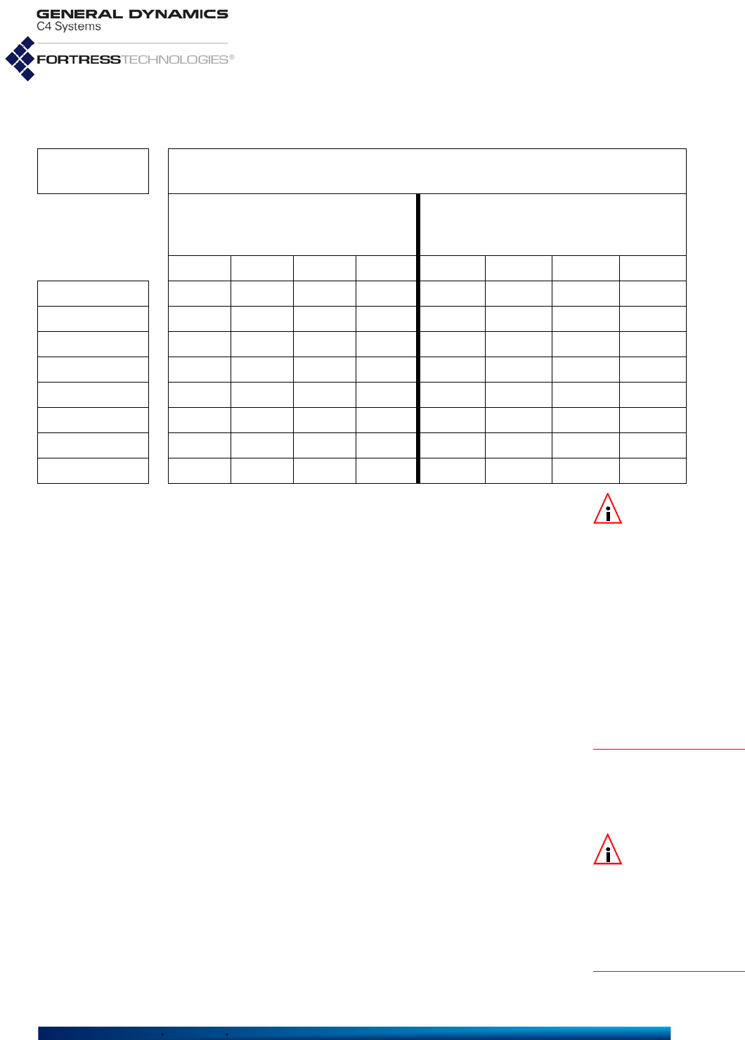
Fortress ES-Series CLI Guide: Networking and Radio Configuration
63
NOTE: It is possi-
ble to configure a
rate such as 48, which is
not an 802.11n rate, for
MaxRate or MinRate
on an 802.11n capable
radio. In that case the
MCS chosen will be the
one associated with the
next higher 802.11n rate.
For 48, that would be
rate "52", or MCS 5 or
13, depending on the
other radio configura-
tion settings.
Table 3.8 can also be used to figure out the range of unicast
transmission rates the radio will use when RateMode auto and
the MaxRate and MinRate are configured. For example, look
up each of those rate settings under the correct configuration
options, and the results will give the top and bottom of the
range.
3.4.9.6 BSS WMM QoS Setting
Traffic received on BSSs enabled for Wi-Fi Multimedia (WMM)
QoS (Quality of Service) is prioritized according to the WMM
tags included in its VLAN tags, if present, or directly in its
802.11 headers, if no VLAN tags are present. WMM is enabled by
default.
When WMM is disabled, traffic received on the BSS is treated as
untagged and marked for Medium (or Best Effort) QoS
handling (Section 3.10). The internal marking is used if the data
is transmitted out an interface that requires marking (such as
another WMM-enabled BSS or an 802.1Q VLAN trunk).
NOTE: BSSs serv-
ing as
Core
inter-
faces in an FP Mesh
network (Section 3.2.2)
should be enabled for
WMM
, to allow prioritiza-
tion of FP Mesh control
packets
.
On ES210 Mesh Points in Station Mode (refer to Section
3.4.11), WMM is also enabled by default on new STA
Interfaces (as described in Section 3.4.11).
3.4.9.7 BSS Fragmentation and RTS Thresholds
The fragmentation threshold (FragThreshold) allows you to
configure the maximum size of the frames the BSS sends
whole. Frame sizes larger than the specified threshold are
broken into smaller frames before they are transmitted. An
Table 3.8 Fixed Unicast Transmission Rate By MaxRate For 802.11
Max Rate
Setting Actual Radio Setting
FORCE STBC = OFF
and MIMO = ON
(FORCE STBC = ON and MIMO = ON)
or SISO or
NOT MIMO CAPABLE
MCS 10MHz 20MHz 40MHz MCS 10MHz 20MHz 40MHz
6.5 8 6.5 13 27 0 3.25 6.5 13.5
13 9 13 26 54 1 6.5 13 27
19.5 10 19.5 39 81 2 9.75 19.5 40.5
26 11 26 52 108 3 13 26 54
39 12 39 78 162 4 19.5 59 81
52 13 52 104 216 5 26 52 108
58.5 14 58.5 117 243 6 29.25 58.5 121.5
65 15 65 130 270 7 32.5 65 135

Fortress ES-Series CLI Guide: Networking and Radio Configuration
64
acknowledgement is sent for each frame received, and if no
acknowledgement is sent the frame is retransmitted.
FragThreshold is set in bytes:
256
–
2345
, or the function can
be turned
off
(the default).
Fragmentation becomes an advantage in networks that are:
experiencing collision rates higher than five percent
subject to heavy interference or multipath distortion
serving highly mobile network devices
A relatively small fragmentation threshold results in smaller,
more numerous frames. Smaller frames reduce collisions and
make for more reliable transmissions, but they also use more
bandwidth. A larger fragmentation threshold results in fewer
frames being transmitted and acknowledged and so can
provide for faster throughput, but larger frames can also
decrease the reliability with which transmissions are received.
The RTS threshold (RtsThreshold) allows you to configure the
maximum size of the frames the BSS sends without using the
RTS/CTS protocol. Frame sizes over the specified threshold
cause the BSS to first send a Request to Send message and
then receive a Clear to Send message from the destination
device before transmitting the frame.
The RTS protocol threshold is set in bytes:
1
–
2345
, or the
function can be turned
off
(the default).
The smaller the RTS threshold, the more RTS/CTS traffic is
generated at the expense of data throughput. On large busy
networks, however, RTS/CTS speeds recovery from radio
interference and transmission collisions, and a relatively small
RTS Threshold may be necessary to achieve significant
improvements.
3.4.9.8 BSS DTIM Beacon Countdown
NOTE: The beacon
interval is config-
ured with set radio
-beaconint, as des-
cribed in Section 3.4.3.
APs buffer broadcast and multicast messages for devices on
the network and then send a Delivery Traffic Indication
Message to “wake-up” any inactive devices and inform all
network clients that the buffered messages will be sent after a
specified number of beacons have been transmitted.
The value specified with -dtim determines the number of
beacons in the countdown between transmitting the initial
DTIM and sending the buffered messages.
Set the DTIM beacon countdown (-dtim) in whole numbers:
1–255
, inclusive (the default is
1
).
A longer DTIM beacon countdown conserves power by
permitting longer periods of inactivity for power-saving devices,
but it also delays the delivery of broadcast and multicast
messages. Too long a delay can cause multicast packets to go
undelivered.

Fortress ES-Series CLI Guide: Networking and Radio Configuration
65
3.4.9.9 BSS VLANs Settings NOTE: Packets
belonging to a
BSS's native VLAN, as
established by
VlanId
,
are always allowed to
traverse a trunk link; so
untagged packets are
always allowed.
VlanId assigns a VLAN ID between
1
and
4094
to the BSS. By
default all interfaces are assigned VLAN ID 1. If the VLAN ID
you enter is not already present in the Active VLAN Table
(Section 3.11.1), it will be automatically added. A new VLAN ID
configured in this way will not yet be associated with an IPv4
address. Refer to Section 3.11.1 for instructions on associating
a new VLAN with an IP address.
SwitchingMode determines whether the BSS will act as a
trunk
or
access
(the default) interface in Fortress’s VLANs
implementation. SwitchingMode is automatically fixed on
Trunk
when WDS is enabled.
AllowAll (or
-vlanAllowAll
) and Table (or
-vlanActiveList
)
configure VLAN trunk filtering for the interface, when the
interface SwitchingMode is
trunk
. When AllowAll is
Y
(yes,
the default), no filtering takes place on the interface. If you set
AllowAll to
n
(no), the interface accepts only packets with
VLAN tags matching a VLAN ID that has been specified for the
BSS using the Table option. (When SwitchingMode is
access
,
these options have no effect.)
3.4.9.10 BSS Fortress Security Zone
Zone places the BSS in the Mesh Point’s
clear
or
encrypted
zone.
Traffic in the encrypted zone is subject to Fortress’s Mobile
Security Protocol (MSP), as configured on the Mesh Point itself
(refer to Section 4.1).
By default BSSs are created in the encrypted zone. When
WDS is enabled, the BSS’s Zone value is fixed on
encrypted
and cannot be changed.
Configuring a BSS to reside in the clear zone exempts all traffic
on that BSS from MSP.
Standard Wi-Fi security protocols can be applied to the traffic
on a BSS (Section 3.4.9.15, below), regardless of whether the
BSS is in the
clear
or
encrypted
zone.
3.4.9.11 FastPath Mesh BSS Cost Offset
The UCostOffset setting applies only when FastPath Mesh
(Section 3.2) is licensed and enabled on the Mesh Point.
UCostOffset specifies a non-negative integer, between
0
(zero, the default) and
4,294,967,295
, by which you can weight
the interface more or less heavily in the FP Mesh cost
equation. The higher the offset, the less attractive the interface,
with the maximum (4,294,967,295) causing the interface to
never be used to route network traffic.

Fortress ES-Series CLI Guide: Networking and Radio Configuration
66
3.4.9.12 BSS Multicast Settings NOTE:McastRate
is dynamic and is
not user configurable for
bridging-enabled BSSs.
McastRate specifies the lowest bit rate at which a BSS
configured to act as a network AP (EnableWds
n
) will send
multicast frames, in megabits per second.
BSSs on a radio that is fixed on the 5 GHz 802.11a band, or
configured by default to use the 5 GHz 802.11a band, have a
default McastRate of
6
Mbps, which is appropriate for a BSS
using the 5 GHz frequency band. Fortress recommends
leaving BSSs in the 802.11a band, including all 802.11na
options, at the default of
6
.
BSSs on a radio configured by default to use the 2.4 GHz
802.11g band have a default McastRate of
1
Mbps, which is
appropriate for a BSS using the 2.4 GHz frequency band.
Fortress recommends leaving BSSs in the 802.11g band,
including all 802.11ng options, at the default of 1.
EnhancedMcast
is an advanced function inappropriate for typical
Mesh Point deployments. Do not modify this setting, except as
directed by a Fortress representative.
3.4.9.13 Bridging MTU and Beacon Encryption
On bridging BSSs (EnableWds
y
), WdsMtu configures the
Maximum Transmission Unit for the interface as appropriate for
wireless (
wifi
) or Ethernet (
ether
) transmissions. The default
WdsMtu is
wifi
.
NOTE:
BeaconEn-
crypt
cannot be
reconfigured after a BSS
is created. You must
delete, and then recreate
the BSS with the new
setting, in order to
change it.
On bridging BSSs (EnableWds
y
), you can use
BeaconEncrypt
enable
to encrypt the entire contents of 802.11 beacon frames.
At the default, disabled (
BeaconEncrypt
disable
), 802.11
management frame contents, including beacons, are
transmitted as cleartext, as is typically the case in wireless
bridging implementations.
BeaconEncrypt
must be enabled (or disabled) on both ends of
the bridging link. Full implementation of the function requires it
to be enabled on all BSSs forming the WDS network.
3.4.9.14 BSS Description
You can optionally enter a Description of the BSS of up to 32
characters. To include spaces in the description string, enclose
it in quotation marks.
As an alternative to interactive configuration, you can use the
add bss command with valid switches and arguments to
configure any of the settings described above when you create
a new BSS:
# add bss -radio radio1|radio2 -name
<BSSname>
-ssid random|
<ssid>
-wds y|n
-minRSS -95–0 -adminstate enable|disable -adssid y|n
-dropbcpr y|n
-idletimeout
<minutes>
-only11g y|n -ratemode auto|fixed -maxrate 1|2|5.5|11|6|9|12|18|24|36|48|54
-minrate 1|2|5.5|11|6|9|12|18|24|36|48|54 -wmm enable|disable -frag off|256–2345
-rts off|256—2345 -dtim 1–255 -vlanID 1—4094 -switchingmode trunk|access
-vlanAllowAll y|n -vlanActiveList 1,2,3...4094 -zone encrypted|clear

Fortress ES-Series CLI Guide: Networking and Radio Configuration
67
-ucost 0–4294967295 -mcastRate 1|2|5.5|11|6|9|12|18|24|36|48|54 -enhancedmcast y|n
-wdsmtu wifi|ether -beaconencrypt enable|disable -desc
<“descriptive string”>
-1X11i none|wpa|wpapsk|wpa2|wpa2psk| wpa2mixed|wpa2mixedpsk -keytype hex|ascii
-wpakey
<wpaKey>
-wpakeyconfirm
<wpaKey>
-rekeyperiod 0—2147483647
-gmkrekeyperiod 0—2147483647 -radiusperiod 0—2147483647 -strictrekey y|n
-reauthperiod 0—2147483647 -preauth y|n
3.4.9.15 BSS Wi-Fi Security Configuration
BSSs on Fortress Mesh Point radios support WPA (Wi-Fi
Protected Access) and WPA2 security.
When you choose an 802.1X/11i Security setting other than
none
(the default), the Mesh Point CLI prompts you for the
additional inputs required by the security method you choose.
802.1X/11i Security (none|wpa|wpapsk|wpa2|wpa2psk|wpa2mixed|wpa2mixedpsk): wpa2
WpaKeyFormat[hex] (hex|ascii to set key string format): hex|ascii
WpaKey[""] (WPA key with length 64(hex), 8..63(ascii)):
<hexORasciiKey>
WpaKeyConfirm[""] (confirm WPA key):
<hexORasciiKey>
GtkRekeyInterval (group transient key (GTK) rekey interval in seconds):
<GTKeyInterval>
GmkRekeyInterval (group master key (GMK) rekey interval in seconds):
<GMKeyInterval>
GtkStrictRekey (Y|N to rekey GTK when a STA leaves the BSS): y
ReauthInterval (EAPOL reauthentication interval in seconds):
<ReAuthInterval>
PreAuth[N] (Y|N to set RSN pre-authentication): y
WPA (wpa), WPA2 (wpa2) and WPA2-Mixed (wpa2mixed)
are enterprise modes of WPA. You can specify wpa or wpa2
to be used exclusively by the BSS, or you can configure it
to use either by specifying wpa2mixed.
WPA and WPA2 use EAP-TLS (Extensible Authentication
Protocol-Transport Layer Security) to authenticate network
connections via X.509 digital certificates. For the Mesh
Point to successfully negotiate a WPA/WPA2 transaction,
you must have specified a locally stored key pair and
certificate for the Mesh Point to use to authenticate the
connecting device as an EAP-TLS peer, and at least one
CA (Certificate Authority) certificate must be present in the
local certificate store. Refer to Section 4.2 for guidance on
configuring an EAP-TLS key pair and digital certificate.
These additional settings apply to wpa, wpa2 and
wpa2mixed
selections:
rekeyperiod (GtkRekyInterval) - specifies the
interval at which Group Transient Keys are
regenerated. The default is zero (
0
), which value
disables the rekeying function; the same key will be
used for the entire session. Specify a new interval in
whole seconds between
0
and
2147483647,
inclusive.
gmkrekeyperiod (GmkRekyInterval) - specifies the
interval at which the Group Master Key is are
regenerated. The default is
1800
. A zero (
0
) value
disables the rekeying function. Specify a new interval in
whole seconds between
0
and
2147483647,
inclusive.

Fortress ES-Series CLI Guide: Networking and Radio Configuration
68
radiusperiod (RadiusRetryInterval) specifies the
number of seconds (0—2147483647) between retries of
the primary authentication server. The default is 0
(zero), which disables the function: If the primary Wi-Fi
authentication server cannot be reached on the initial
attempt, it is not retried until all configured network
servers (secondary, tertiary, etc.) have been tried in turn
and also failed.
strictrekey (
GtkStrictRekey
) - enter
y
or
n
to indicate
whether to automatically rekey whenever a STA leaves
the BSS.
reauthperiod - to ensure that a peer whose certificate
has been revoked is not allowed to remain associated,
you can establish a reauthentication period. Any peer
with a certificate that is no longer valid will be dropped.
Specify an interval in whole seconds between
0
and
2147483647,
inclusive. The default is
3600
. See Section
4.2.2.3 for additional information on Certificate
Revocation.
preauth - to facilitate roaming between network access
points, enabling preauthentication on the BSS permits
approaching WPA2 wireless clients to authenticate on
the Mesh Point while still connected to another network
access point, while wireless clients moving away from
the Mesh Point can remain connected while they
authenticate on the next network AP. By default,
preauth is set to
n
(disabled).
For WPA-PSK (pre-shared key), WPA2-PSK and WPA-
Mixed-PSK (
wpapsk
,
wpa2psk
,
wpa2mixedpsk
) you can set
the interval, in seconds, between key exchanges
(rekeyperiod). The default is zero (
0
), which value
disables key exchange; the same key will be used for the
entire session. You must also specify whether the pre-
shared key will be an
ascii
plaintext passphrase of 8–63
characters or a 64-digit
hex
adecimal string and then enter
the key itself:
You can use the same switches with the update command to
edit BSS settings.
You can delete a specified BSS or all configured BSSs with the
del command:
# del bss -all|-name
<name>
You must be logged on to an
administrator
-level account to
change configuration settings (refer to Section 2.2).

Fortress ES-Series CLI Guide: Networking and Radio Configuration
69
3.4.10 Antenna Tracking / Rate Monitoring NOTE: A Mainte-
nance user can run
the show tracking com-
mand in continuous
mode (-samples 0) while
an Administrative user
adjusts the radio and
bss configuration for
best link quality.
Administrative and Maintenance users have the ability to
monitor the data rate and RSSI of a specific WDS link between
two Fortress Mesh Points using the show command:
# show tracking -mac <macAddr> -radio <RadioName> -interval <Interval>
-samples <Samples> -format <Format>
macAddr is the MAC address of the specific radio of the
Fortress Mesh Point to which this FMP is connected. An FMP
has a base MAC address, but it also has individual MAC
addresses for each radio. To figure out which address to use,
run the show bss command on the remote FMP. Use the
BssId MAC address of the appropriate BSS on the remote
FMP as the macAddr in the command on this FMP.
CAUTION: The
show tracking
command may have an
impact on the perfor-
mance of the FMP and
the throughput of data
on the channel.
RadioName is the name of the radio on this FMP that connects
to the remote FMP. The default radio name is radio2.
Interval is the time in milliseconds between lines of
monitoring output. The default interval is 100 milliseconds, or
10 output lines per second.
Samples is the number of output lines to emit. The default
number of samples is 50 lines. If you enter 0, the output lines
will continue to show until you hit Ctrl-C to stop the output.
CAUTION: The
show tracking
command should never
be run by more than one
user simultaneously.
Format is the format of the output. The default (and only
current capability) is format 1, which is:
$BATSR,RADIO_NAME,VERSION,MODE,LINK_STATUS,RSSI,LINK_SPEED,LINK_DISTA
NCE,REMOTE_IP,REMOTE_MAC,*CHECKSUM
# show tracking -mac 00:14:8c:00:0a:b4
$BATSR,ES-00148cf80780radio2,5.4.5.2041-CS,WDS,Connected,-41,54,N/
A,N/A,00:14:8c:00:0a:b4,*7e
In this example, BATSR is a hardcoded string that refers to this
format. WDS is the mode. LINK_DISTANCE and REMOTE_IP
are unavailable, so they are shown as N/A. 00:14:8c:00:0a:b4
is the MAC address of the remote FMP. It will always be the
same MAC that was requested in the show command. Finally
the *7e is the NMEA-0183-compliant XOR data sum prefixed
by '*'.
This command is useful when trying to aim the FMP's antenna
in a new installation, and also when trying to debug link quality
issues. For best results, the LINK_SPEED value should be as
high as possible. The RSSI should be the smallest absolute
number (e.g. -47 is much better than -85), but not past -35 for
ES820s and ES2440s, and not past -25 for ES520s.

Fortress ES-Series CLI Guide: Networking and Radio Configuration
70
3.4.11 ES210 Mesh Point STA Settings and
Operation NOTE:
Each Mesh
Point radio can
alternatively support up
to four
BSS
interfaces.
Refer to Section 3.4.9.
Configuring a station (sta or STA) interface on the ES210
Mesh Point radio causes the Mesh Point to act as a dedicated
WLAN client device, or station, rather than as an AP or a
wireless bridge (or FastPath Mesh Point).
An ES210 configured with such an interface is in station mode.
Only a single STA Interface is permitted on a given ES210, and
when one is present, no additional wireless interface of any
type can be configured. If one or more BSSs have been
configured on the Mesh Point radio, you must delete all BSSs
before you can enable a STA interface.
NOTE:
On the
ES210, the port
Ethernet1 is labeled
Ethernet (WAN) on the
chassis, and Ethernet2 is
labeled Ethernet.
Station mode is supported only by the ES210 Mesh Point.
A STA interface can only bridge between a wireless network
AP and one or more Ethernet devices connected to the clear
Ethernet port(s) on the ES210. In addition, no wired (Ethernet)
bridging can occur when the Mesh Point is in station mode. An
ES210 in STA mode does not support Fast Path Mesh bridging
(Section 3.2.2), but can function, like other wireless devices, as
an NMP (non-Mesh Point) on a FastPath Mesh Network. In
other words, an ES210 in STA mode should be configured to
run STP bridging mode rather than MESH bridging mode.
For example, on an ES210 on which the Ethernet2 port is clear
and the Ethernet1 port is encrypted (the defaults), a typical
station mode setup would use the Ethernet2 port to connect
one or more Ethernet devices. If the Ethernet1 port is in the
clear zone, it can be used in the same way. Devices on a clear
Ethernet port, however, cannot communicate with devices on
an encrypted Ethernet port when the ES210 is in station mode.
You can preconfigure a STA interface with the settings required
to connect to a specific network. Alternatively, you can scan for
available networks within range and select one to use to create
the sta interface that will connect the ES210 to the network.
In order to facilitate the ES210 Mesh Point's Station Mode
network scanning function, a temporary STA interface,
__FORTRESS__TEMP_STA__, is present in the default
configuration. This STA Interface must be enabled in the GUI
before it will be visible in the CLI (see the Fortress Mesh Point
Software GUI Guide). View the default station configuration
with show sta:
# show sta
RadioName: radio1
Name: __FORTRESS__TEMP_STA__
Ssid: __FORTRESS__TEMP_STA__
Bssid: 00:00:00:00:00:00
AdminState: enable

Fortress ES-Series CLI Guide: Networking and Radio Configuration
71
WMM: enable
FragThreshold: off
RtsThreshold: off
Zone: clear
Description:
802.1X/11i Security: none
RateMode: auto
MaxRate: 54
MinRate: 1
McastRate: 1
StaId: 00:14:8c:2a:0c:90
Operational Status: up
Access Point: 00:00:00:00:00:00
You can use update sta to overwrite these parameters, or
delete this STA configuration entirely and add a new one with
the necessary parameters.
3.4.11.1 STA Radio, Name, SSID and SSID Roaming
The minimum parameters required to create a new STA
interface are to identify the radio (-radio) on which it will be
created, name the STA (-name) and provide an SSID of up to
32 characters.
# add sta -radio radio1 -name station1 -ssid ssid1
[OK]Warning: 802.1X/11i Security is set to none and zone is set to clear!
The above example creates a STA with these default settings:
# show sta
RadioName: radio1
Name: station1
Ssid: ssid1
Bssid: 00:00:00:00:00:00
AdminState: enable
BgScan: disable
BgScanIdlePeriod: 250
BgScanInterval: 60
WMM: enable
FragThreshold: off
RtsThreshold: off
Zone: clear
Description:
802.1X/11i Security: none
RateMode: auto
MaxRate: 54
MinRate: 6
McastRate: 6
StaId: 00:14:8c:f8:18:d0
Operational Status: up
Access Point: Not-Associated

Fortress ES-Series CLI Guide: Networking and Radio Configuration
72
Except for the Zone and the final lines of output (beginning with
StaId, which displays the STA’s MAC address), each of the
settings shown above can be configured with add sta:
# add sta -radio
radio1
RadioName[radio1] (radio1 name of radio interface):
radio1
StaName (string for identity): <
NewStation>
Ssid (string(32 chars max)): NewStationSSID
Bssid (MAC address of AP):
AdminState (enable|disable to set STA administrative state):
RateMode (auto|fixed to set bit-rate adaptation mode):
MaxRate (1|2|5.5|11|6|9|12|18|24|36|48|54 to set maximum transmission rate in Mbps):
MinRate (1|2|5.5|11|6|9|12|18|24|36|48|54 to set minimum transmission rate in Mbps):
BgScan (enable|disable to set background scan support):
BgScanIdlePeriod (100..60000 to set background scan idle period in milliseconds):
BgScanInterval (15..86400 to set background scan interval in seconds):
WMM (enable|disable to set Wi-Fi Multimedia (WMM) support):
FragThreshold (off|256..2345 to set maximum fragment size):
RtsThreshold (off|1..2345 to set minimum packet size for RTS/CTS handshake):
McastRate (1|2|5.5|11|6|9|12|18|24|36|48|54 to set multicast transmission rate in Mbps):
Description (string of description):
802.1X/11i Security (none|wpa|wpapsk|wpa2|wpa2psk|wpa2mixed|wpa2mixedpsk):
wpapsk
WpaKeyFormat (hex|ascii to set WPA key string format):
ascii
WpaKey (WPA key with length 64/hex, 8..63/ascii):
00000000
WpaKeyConfirm (confirm WPA key with length 64/hex, 8..63/ascii):
00000000
PtkRekeyInterval (pairwise transient key (PTK) rekey interval in seconds):
600
To create a STA Interface, specify a StaName of up to 254
alphanumeric characters to identify the interface in the Mesh
Point configuration. You cannot edit the StaName after the STA
Interface has been created.
Certain interface names and prefixes, such as aux and sta_
for examples, are reserved for internal use. If the StaName you
enter is reserved, the Mesh Point CLI will return an error
requiring you to modify your entry.
Specify the network SSID to which the ES210 Mesh Point will
associate. To determine which networks are available, you can
use show scan (refer to Section 3.4.11.11). To disable roaming
among multiple APs with the same SSID, in Bssid, specify the
MAC address of a single wireless AP to which the STA
Interface is permitted to associate.
3.4.11.2 STA State
AdminState determines whether the interface is disabled or
enabled. A newly added STA is
enabled
by default.
3.4.11.3 STA Unicast Transmission Rate Settings
When a STA Interface is configured to use a RateMode setting
of
auto
(the default), the interface dynamically adjusts the bit
rate at which it transmits unicast data frames—throttling

Fortress ES-Series CLI Guide: Networking and Radio Configuration
73
between the configured MaxRate and MinRate—to provide the
optimal data rate for the connection.
At a RateMode setting of
fixed
, the interface will use the
configured MaxRate for all unicast transmissions and ignore the
configured MinRate.
Transmission rates are set in megabits per second (Mbps).
MaxRate can be set only to a value greater than or equal to the
currently configured MinRate, which likewise can be set only to
a value less than or equal to the configured MaxRate. Usable
values for transmission rate settings depend on the Band
setting for the radio on which the STA Interface is configured,
as shown in Table 3.8 in Section 3.4.9.5 above.
NOTE: Radio Band
settings are cov-
ered in detail in Section
3.4.
Please refer to Section 3.4.9.5 for information on default
MaxRate and MinRate settings.
3.4.11.4 STA Background Scanning
To permit background scanning for available APs, set Bgscan
to
enabled
. The default is
disabled
. Background scanning
enables the STA to scan periodically so that show scan data
remains current. (The show scan command is covered in more
detail in Section 3.4.11.11.)
BgScanIdlePeriod indicates how long the STA must be idle
before going off-channel as part of background scan, in
milliseconds between
100–60000
(the default is
250
ms idle
time). If the STA is very busy sending and receiving traffic,
going off channel would be highly detrimental to traffic flow. If
the traffic volume is low, background scanning can occur with
no user impact.
BgScanInterval indicates how often the STA initiates a
background scan. Set this value in seconds:
15–86400
(the
default is
60
seconds).
3.4.11.5 STA WMM QoS Setting
When Wi-Fi Multimedia QoS (Quality of Service) is
Enabled
(the default) on the STA Interface, it advertises that it is capable
of WMM. If the AP to which the STA Interface associates is
also enabled for WMM, WMM will be used for the association. If
the AP is not capable of and enabled for WMM, having WMM
Enabled
on the STA Interface will have no effect.
WMM is
enabled
by default for a STA interface.
In a WMM enabled association, packets sent from the Mesh
Point include WMM tags that permit traffic from the Mesh Point
to be sorted according to the priority information contained in
those tags.

Fortress ES-Series CLI Guide: Networking and Radio Configuration
74
3.4.11.6 STA Fragmentation and RTS Thresholds
The fragmentation and RTS protocol thresholds are set in
bytes:
256
–
2345
for FragThreshold and
1
–
2345
for
RtsThreshold—or these functions can be turned
off
(the
default for both). The Delivery Traffic Indication Message
(-dtim) beacon countdown can be set in whole values
1–255
,
inclusive (the default is
1
).
3.4.11.7 STA Multicast Rate
Please refer to Section 3.4.9.12 for information on the STA
Multicast Rate.
3.4.11.8 STA Description
You can optionally enter a description of the interface of up to
100 characters. To include spaces in the description string,
enclose it in quotation marks.
3.4.11.9 STA Wi-Fi Security Configuration
By default, no Wi-Fi security is applied to traffic on a STA
Interface. Traffic on a STA Interface with a Wi-Fi Security setting
of
None
is unsecured.
3.4.11.9.1 WPA, WPA2 and WPA2-Mixed Security
You can specify that
WPA
or
WPA2
be used exclusively by the
STA Interface, or you can configure it to be able to use either
by selecting
WPA2-Mixed
.
WPA and WPA2 use EAP-TLS (Extensible Authentication
Protocol-Transport Layer Security) to authenticate network
connections via X.509 digital certificates. You must have
specified a locally stored key pair and certificate to use to
authenticate the Mesh Point as an EAP-TLS peer, and at least
one CA (Certificate Authority) certificate must be present in the
local certificate store. Refer to Section 4.2 for guidance on
configuring an EAP-TLS key pair and digital certificate.
These additional settings apply to
WPA
,
WPA2
and
WPA2-Mixed
selections:
rekeyperiod (PtkRekeyInterval) - specifies the interval
at which new pair-wise transient keys (PTKs) are
negotiated. The default is 0 (zero), which disables the
rekeying function. Specify a new interval in whole seconds
between
0
and
2147483647,
inclusive.

Fortress ES-Series CLI Guide: Networking and Radio Configuration
75
NOTE: Unlike
Suite B Key
Establishment (Sec-
tion 4.1.5), the
Suite B
TLS Cipher option is
available regardless of
whether Suite B is
licensed on the Mesh
Point (Section 5.6).
tlscipher - specifies the list of supported cipher suites,
the sets of encryption and integrity algorithms, that the
Mesh Point will send to the 802.1X authentication server:
All
- the default, supports both
Legacy
and
Suite B
cipher suites (as described in the next two items)
Legacy
- supports Diffie-Hellman with RSA keys
(DHE-RSA-AES128-SHA and DHE-RSA-AES256-SHA)
Suite B
- supports Diffie-Hellman with ECC keys
(ECDHE-ECDSA-AES128-SHA and ECDHE-ECDSA-
AES256-SHA)
In EAP-TLS, the authentication server selects the cipher
suite to use from the list of supported suites sent by the
client device (or rejects the authentication request if none of
the proposed suites are acceptable).
subjectmatch - optionally provides a character string to
check against the subject Distinguished Name (DN) of the
authentication server certificate. Each RDN (Relative
Distinguished Name) in the sequence comprising the
certificate DN is compared to the corresponding RDN in the
string provided. When subjectmatch is not specified, no
subject DN check is performed.
certhash - optionally provides a 64-character hash value
to check against the hash value of the authentication server
certificate. If no value is provided for certhash, no hash
value check is performed.
3.4.11.9.2 WPA-PSK, WPA2-PSK and WPA2-Mixed-PSK Security
WPA-PSK (Wi-Fi Protected Access) and WPA2-PSK are the
pre-shared key modes of WPA (as distinguished from the
enterprise modes described above). You can specify that
WPA-
PSK
or
WPA2-PSK
be used exclusively by the STA Interface, or
you can configure it to be able to use either by selecting
WPA2-
Mixed-PSK
.
Pre-shared key mode differs from enterprise mode in that PSK
bases initial key generation on a user-specified key or
passphrase instead of through digital certificates. Like
enterprise-mode, PSK mode generates encryption keys
dynamically and exchange keys automatically with connected
devices at user-specified intervals.

Fortress ES-Series CLI Guide: Networking and Radio Configuration
76
NOTE:
The
tlscipher,
subjectmatch,
and
certhash
settings do
not apply when
WPA-
PSK
,
WPA2-PSK
,
WPA2-
Mixed
or
None
is
selected for
802.1X/
11i Security.
These additional settings apply to
WPA-PSK
,
WPA2-PSK
and
WPA2-
Mixed-PSK
selections:
PtkRekeyInterval (-rekeyperiod) - specifies the
interval at which new keys are negotiated. Specify a new
interval in whole seconds between
1
and
2147483647
,
inclusive, or
0
(zero), to permit the same key to be used for
the duration of the session.
WpaKeyFormat (-keytype) - determines whether the
specified key is an
ascii
passphrase or a
hex
adecimal key.
WpaKey and WpaKeyConfirm - specify the preshared key
itself, as:
a plaintext passphrase between 8 and 63 characters in
length, when
ascii
is selected for keytype.
a 64-digit hexadecimal string, when
hex
is selected for
keytype.
# add sta -radio
<RadioName>
-name
<StaName>
-ssid
<Ssid>
-bssid
<Bssid>
-adminstate enable|disable -ratemode auto|fixed -maxrate 1|2|5.5|11|6|9|12|18|24|36|48|54
-minrate 1|2|5.5|11|6|9|12|18|24|36|48|54 -bgscan enable|disable -bgscanIdlePeriod 100–60000
-bgscaninterval 15–86400 -wmm enable|disable -frag off|256–2345 -rts off|256—2345
-mcastRate 1|2|5.5|11|6|9|12|18|24|36|48|54 -desc <“descriptive string”>
-1X11i none|wpa|wpapsk|wpa2|wpa2psk|wpa2mixed|wpa2mixedpsk -keytype hex|ascii
-wpakey
<64/hex>
|
<8..63/ascii>
-wpakeyconfirm
<64/hex>
|
<8..63/ascii>
-rekeyperiod <
rekeyseconds
> -tlscipher all|legacy|suite-b -subjectmatch <substring>
-certhash <hash>
3.4.11.10 Editing or Deleting a
STA Interface
Connection
You can use the same switches with the update command to
edit STA settings.
# update sta -name
<StaName>
-ssid
<Ssid>
-bssid
<Bssid>
-adminstate enable|disable
-ratemode auto|fixed -maxrate 1|2|5.5|11|6|9|12|18|24|36|48|54
-minrate 1|2|5.5|11|6|9|12|18|24|36|48|54 -bgscan enable|disable -bgscanIdlePeriod 100–60000
-bgscaninterval 15–86400 -wmm enable|disable -frag off|256–2345 -rts off|256—2345
-mcastRate 1|2|5.5|11|6|9|12|18|24|36|48|54 -desc <“descriptive string”>
-1X11i none|wpa|wpapsk|wpa2|wpa2psk|wpa2mixed|wpa2mixedpsk -keytype hex|ascii
-wpakey
<64/hex>
|
<8..63/ascii>
-wpakeyconfirm
<64/hex>
|
<8..63/ascii>
-rekeyperiod <rekeyseconds> -tlscipher all|legacy|suite-b -subjectmatch <substring>
-certhash <hash>
You can delete the STA interface with the del command:
# del sta -all|-name
<StaName>
You must be logged on to an
administrator
-level account to
change configuration settings (refer to Section 2.2).
3.4.11.11 Establishing a
STA Interface
Connection
You can use the ES210 Mesh Point’s scan function to detect
networks within range of the Mesh Point. A STA Interface must
be present and enabled (-adminstate enable), and the Mesh

Fortress ES-Series CLI Guide: Networking and Radio Configuration
77
Point radio must also be enabled before you can scan for a
network to connect to.
Scan for available networks using show scan. Use more to
break the list after a page of output.
> show scan more
SSID BSSID Channel RSSI Security
-------------------------------- ----------------- ------- ---- ------------
00:14:8c:f8:29:94 149 60 none
210tofcx 00:14:8c:1e:ab:d0 9 10 wpa2
AWAN 00:1d:e6:24:86:f0 6 15 wpa
Base-11a 00:14:8c:08:3b:c2 149 63 none
Base-11g 00:14:8c:f6:00:c3 1 61 none
Free Public WiFi 02:12:f0:0a:e9:39 11 22 none
GUEST 00:1d:e6:24:86:f1 6 15 none
WIRELESS 02:60:a5:ee:e0:b3 11 24 none
peg10wpa2 00:14:8c:08:26:50 165 18 wpa2psk
vsc-tf 00:25:9c:67:aa:86 6 35 wpa2mixedpsk
--- Total Scanned APs: 10
If the network you will be connecting to uses WPA, WPA2 or
WPA2-Mixed to authenticate connecting devices, you must
import a valid EAP-TLS digital certificate for the STA Interface
before the ES210 Mesh Point will be permitted to connect.
Refer to Section 4.2 for guidance.
If the network you will be connecting to uses WPA-PSK, WPA2-
PSK or WPA2-Mixed-PSK, you will be required to enter a valid
pre-shared key for the STA Interface, as described below,
before the Mesh Point will be permitted to connect. Refer to
WPA-PSK, WPA2-PSK and WPA2-Mixed-PSK Security in
Section 3.4.11 for more on the pre-shared key.
If the connection requires a pre-shared key for authentication,
you must specify whether it is an
ascii
or
hex
adecimal string
and enter, then re-enter, the correct key, as described under
WPA-PSK, WPA2-PSK and WPA2-Mixed-PSK Security in
Section 3.4.11.
If the connection uses a digital signature for authentication, you
can optionally configure the additional security options
described under WPA, WPA2 and WPA2-Mixed Security in
Section 3.4.11.

Fortress ES-Series CLI Guide: Networking and Radio Configuration
78
3.4.11.12 ES210 Station Access Control Lists
When the STA Interface is using WPA, WPA2 and WPA2-Mixed
Security, an additional level of security can be provided via an
Access Control List (ACL).
The Station ACL function is enabled when any ACL entry is
administered. Once the ACL is enabled, the Mesh Point
compares the X.509 digital certificates of 802.1X authentication
servers against the filter criteria in the ACEs contained in the
ACL, in the specified Priority order. If no match is found,
access is denied. If a match is found, access is allowed or
denied according to the ACL entry’s Access rule.
The ACEs available for inclusion on the ACL are created using
add ace, and edited using update ace. (see Section 4.3).
Once Access Control Entries have been created, they can be
added to the Station ACL using add station-acl.
# add station-acl -name
<ACEname>
-access allow|deny -priority 1-100
You can configure up to 100 ACL entries to be applied in the
specified priority.
Name identifies the ACE that you want to add to the station
ACL. View a list of available ACE names with show ace (see
Section 4.3).
Priority establishes the order in which the ACL entry will be
applied, from
1
to
100
, relative to other configured ACL entries.
Priority values must be unique. Entries with lower priority
numbers take precedence over those with higher priority
numbers.
Access determines whether the Mesh Point will
Allow
or
Deny
(the default) access to an authentication server whose X.509
certificate matches the criteria specified in the ACL entry.
View the entries in the Station ACL using show:
# show station-acl
Prio Type ACE Name
---- ----- --------------------
--- Total ACLs: 0
Use del station-acl to remove entries from the Station ACL.
NOTE: Deleting all
ACL entries dis-
ables the STA Interface
ACL function.
# del station-acl -all|-name
<ACEname>
Deleted ACL entries no longer appear when you run show
station-acl.
3.5 Local Area Network Configuration
Network settings includes those that establish the Mesh Point’s
basic LAN configuration: hostname and IPv4 and IPv6 settings.

Fortress ES-Series CLI Guide: Networking and Radio Configuration
79
3.5.1 Hostname and IPv4 Settings
View basic network properties with the
show
network
command:
>
show network
Current IP values:
IPv4 Enabled:y
Hostname:hostname
IP:192.168.1.9
Netmask:255.255.255.0
DefaultGateway:192.168.1.1
Configured IP values:
IP:192.168.1.9
Mask:255.255.255.0
Gateway:192.168.1.1
NOTE: The For-
tress Mesh Point’s
default IP address is:
192.168.254.254
Current IP values are those actually in use on the IPv4
network. Configured IP values are those specified for the
Mesh Point (by factory defaults or an administrator). These
values can differ briefly between your changing IP values and
the new settings taking effect.
IPv4 is enabled by default. If the Mesh Point is installed on a
network that uses IPv6 exclusively, you can disable IPv4. If the
Mesh Point is installed on an IPv4 network, disabling IPv4
prevents you from managing the Mesh Point via IPv4 through
the Mesh Point GUI and SSH. Additionally, all IPv4 services,
(NTP, SNMP, remote audit logging, external authentication
services, etc.) will be disabled. If the Mesh Point’s internal IPv4
DHCP server is enabled, it, too, will be disabled when IPv4 is
disabled.
Other configurable parameters establish the Mesh Point’s
hostname, assign the IPv4 address and subnet mask of the
Mesh Point’s management interface and identify the IPv4
default gateway (or router) for the network on which you are
installing the Mesh Point.
Configure IPv4 network properties for the Fortress Mesh Point
with the
set
network
command, as follows:
# set network
IPv4Enabled[y] (y|n):y
Hostname[ES-00148c081080]:
<hostname>
IPaddress[192.168.1.9]:
<mngmtIPaddr>
Netmask[255.255.255.0]:
<subnetmask>
DefaultGateway[192.168.1.1]:
<dfltGtwy>
Confirm: Save and use this configuration? (n|y): y
[INFO] This operation may take some time....
[OK]
The Mesh Point CLI displays the configurable fields for set
network one at a time. Enter a new value for the field—or
leave the field blank and the setting unchanged—and strike
Enter↵, to display the next field. The final confirmation query

Fortress ES-Series CLI Guide: Networking and Radio Configuration
80
displays only when you have entered a value into at least one
of the fields presented.
Alternatively, you can run
set
network
non-interactively with
valid switches and arguments in any order and combination:
#
set network -enable y|n -h
<hostname>
-ip
<IPv4addr>
-nm
<subnet_mask>
-gw
<default_gatewayIP>
The Mesh Point CLI returns [OK], when settings are
successfully changed, and informs you that there may be brief
delay before your change(s) take effect.
You must be logged on to an
administrator
-level account to
change configuration settings (refer to Section 2.2).
3.5.2 IPv6 Settings
NOTE:
Incoming
ICMPv6 (Internet
Control Message Proto-
col version 6) packets
require administrative
access. If the adminis-
trative IP address ACL
(disabled by default) is
enabled, it must include
the relevant IPv6
addresses. See Section
2.2.5 for more detail.
Traffic is affected by the
per-interface packet fil-
ters. If configured, per-
interface packet filters
must include filters to
permit ICMPv6 traffic.
See Section 4.6.3 for
more detail.
The Mesh Point supports IPv6, which is always enabled. When
an IPv6 router is present on the network and Automatic
Address is Enabled on the Mesh Point (the default), the Mesh
Point will be automatically provided a compatible IPv6 Global
Address and Prefix Length. Any network IPv6 routers
configured to do so will additionally supply their own addresses
as the Mesh Point’s IPv6 Default Gateways.
View the Mesh Point’s current IPv6 configuration with show
networkv6:
> show networkv6
Current IPv6 values:
Automatic Address Enabled:n
Global Address:2001:DB8:0:0:0:0:0:2
Global Address Prefix Length:128
Link Local Address:FE80:0:0:0:214:8CFF:FE08:1080
Other Addresses:FD00:0:8895:8895:214:8CFF:FE08:1980/64
2099:0:0:0:214:8CFF:FE08:1980/64
Default Gateways:FE80:0:0:0:0:0:0:1 (metric=47)
2001:0:0:0:0:0:0:1 (metric=23)
Configured IPv6 values:
Global Address:2001:DB8:0:0:0:0:0:2
Global Address Prefix Length:128
Gateway:FE80:0:0:0:0:0:0:1
Default Gateway Metric:1024
Prefix lengths for Other Addresses are shown after the
addresses, and the metrics for all Default Gateways are
shown in parentheses).
You can choose to allow all IPv6 settings to be automatically
configured on the Mesh Point, opt to manually configure the
global address and IPv6 gateway/metric, or use both manually
and automatically configured global addresses.

Fortress ES-Series CLI Guide: Networking and Radio Configuration
81
Change the Mesh Point’s IPv6 network settings with set
networkv6 with valid switches and arguments in any order and
combination:
# set networkv6 -auto y|n -ip <IPv6GlobalAddr>
-pl <
prefix_length
>
-gw <IPv6DfltGtwyAddr> -gm <DfltGtwyMetric>
When automatic addressing is at its default of enabled
(-auto y), and there is an IPv6 router on the network
configured to provide the global prefix, the Mesh Point will
automatically configure a compatible IPv6 global address for
itself. If additional IPv6 routers are present, auto-addressing
will configure additional IPv6 global addresses.
If you choose to manually configure IPv6 settings, these
include:
NOTE: Fortress’s
FastPath Mesh
functionality includes
independent IPv6
addressing, which can
supply additional IPv6
ULAs (Unique Local
Addresses, refer to Sec-
tion 3.2.2).
-auto (auto addressing) - configures the Mesh Point to
learn IPv6 global prefixes from network routers (
y
, the
default) or to use only a locally established global address
(
n
).
-ip (configurable global address) - manually establishes an
IPv6 global network address—which must be within the
IPv6 global scope—for the Mesh Point’s management
interface.
-pl (configurable prefix length) - specifies the bit length of
the prefix portion of the Mesh Point’s configurable global
address.
-gw (configurable gateway) - manually provides the IP
address of the default gateway for the Mesh Point’s IPv6
subnet. The default gateway address must be a compatible
link-local or global address (i.e., lie within the same prefix
as either the global address or the link-local address).
If no default gateway is necessary (i.e., you are configuring
the Mesh Point for use on a private network unconnected to
other OSI Layer 3 networks), you need not configure an
IPv6 default gateway.
-gm (configurable gateway metric) - establishes the IPv6
metric, or relative routing cost, for the configurable
gateway, allowing it to be assigned a preference relative to
the automatically assigned default gateways.
You must be logged on to an administrator-level account to
change configuration settings (refer to Section 2.2).
3.5.3 DNS Client Settings
The Mesh Point can be configured as a standard Domain
Name System client.

Fortress ES-Series CLI Guide: Networking and Radio Configuration
82
NOTE:
Mesh Point
software also
includes a standard
DNS service (Section
3.8), and FP Mesh pro-
vides name resolution
within the mesh inde-
pendent of any DNS
service (Section 3.2.2).
View the current DNS client configuration with show:
> show dns-client
Domain: ftimesh.local
Preferred DNS server: Unknown
Alternate DNS server: Unknown
Configure DNS settings with set, which can be used
interactively:
# set dns-client
Domain:
<domainName>
Preferred IP:
<preferredDNSsvrIPaddrs>
Alternate IP:
<alternateDNSsvrIPaddrs>
The Mesh Point CLI displays the configurable fields for set dns
one at a time. Enter a new value for the field—or leave the field
blank and the setting unchanged—and strike Enter↵, to display
the next field.
Alternatively, you can run set dns non-interactively with valid
switches and arguments in any order and combination:
# set dns-client -d
<domainName>
-ip1
<preferredDNSsvrIPaddrs>
-ip2
<alternateDNSsvrIPaddrs>
The Mesh Point CLI returns [OK] when settings are
successfully changed.
You must be logged on to an
administrator
-level account to
change configuration settings (refer to Section 2.2).
3.6 Time and Location Configuration
You should either set the Mesh Point’s internal clock at
installation, or enable and configure its NTP (Network Time
Protocol) function.
3.6.1 System Date and Time
View Mesh Point date and time settings with the
show
clock
command:
> show clock
Sun Jul 15 23:39:39 UTC 2001
You can use the -local switch to show the local time rather
than the default TimeZone, UTC (Universal Time Coordinated):
> show clock -local
Tue Sep 30 23:08:23 ETD 2008
Set system date and time on the Fortress Mesh Point, using
the twenty-four-hour clock and numerical date, through the
set
clock
command, as follows:
# set clock
# set clock -h 14 -m 21 -s 46 -M 12 -D 12 -Y 2010

Fortress ES-Series CLI Guide: Networking and Radio Configuration
83
The set clock command returns the Mesh Point’s current date
and time values, which you can edit and re-enter: use the left/
right arrow keys to navigate displayed fields, backspace over
current values or overwrite them. When you finish typing in new
values, strike Enter↵ to save them. The Mesh Point CLI returns
[OK] when settings are successfully changed.
Alternatively, you can run
set
clock
non-interactively with valid
switches and arguments, as shown below.
# set clock -h
<hrs>
-m
<mins>
-s
<secs>
-M
<M>
-D
<D> -
Y
<YYYY>
To set the Mesh Point’s internal clock in local time rather than
UTC, use the -local switch with set clock.
# set clock -local
# set clock -local -h 10 -m 21 -s 46 -M 12 -D 12 -Y 2008
The Mesh Point CLI returns [OK] when settings are
successfully changed.
You must be logged on to an
administrator
-level account to
change configuration settings (refer to Section 2.2).
3.6.2 Time Zone
View the current time zone setting with show:
> show timezone
America/New_York
The set command is used to change the time zone setting
interactively, displaying allowable country|territory values
for you to enter, and then allowable zone values. Entries are
case-sensitive: enter your choice exactly as it appears in the
list.
# set timezone
Africa, America, Asia, Atlantic, Australia, Brazil, Canada, Europe, Indian, Mexico, Mideast,
Pacific, US,
--> Enter timezone|continent|country|territory name: US
Alaska, Aleutian, Arizona, Central, East-Indiana, Eastern, Hawaii, Indiana-Starke, Michigan,
Mountain, Pacific, Samoa
--> Enter second level timezone|country|state|city|territory name: US/Eastern
The Mesh Point CLI returns [OK] when settings are
successfully changed.
You must be logged on to an
administrator
-level account to
change configuration settings (refer to Section 2.2).
3.6.3 NTP Client Configuration
The Mesh Point supports configuration with up to three
Network Time Protocol (NTP) servers.
View the current NTP configuration with show ntp:

Fortress ES-Series CLI Guide: Networking and Radio Configuration
84
> show ntp
ServerName: primary
IPorHostname: 192.168.10.9
Active: Y
AuthEnabled: N
AuthKeyIndex: 0 (not valid)
ServerName: secondary
IPorHostname:
Active: N
AuthEnabled: N
AuthKeyIndex: 0 (not valid)
ServerName: tertiary
IPorHostname:
Active: N
AuthEnabled: N
AuthKeyIndex: 0 (not valid)
No NTP servers are configured by default.
NOTE:
Incoming
NTP packets
require administrative
access. If the administra-
tive IP address ACL (dis-
abled by default) is
enabled, it must include
IP addresses for the NTP
server(s). See Section
2.2.5 for more detail.
Traffic is affected by the
per-interface packet fil-
ters. If configured, per-
interface packet filters
must include filters to
permit NTP traffic to
and from the FMP. See
Section 4.6.3 for more
detail.
NTP servers are specified by local ServerName (or -name), as
primary, secondary, and tertiary, and added to the Mesh
Point configuration by network IP address or hostname
(IPorHostname, or -ip).
The Active (or -enable) parameter permits you to control
whether or not a configured NTP server is currently in use by
the Mesh Point’s NTP client function.
Optionally, you can configure the Mesh Point to use RSA SHA1
to authenticate incoming NTP packets from a configured NTP
server by specifying
y
(
es
) for AuthEnabled
(-auth y) for the server. In order for the Mesh Point to
successfully authenticate NTP packets from a configured
server, you must also specify a key index value for the server
with AuthKeyIndex (-keyindex). Specify a valid index value
from
1
to
65534
.
Configure a new NTP server for the Mesh Point or change the
settings of an existing server interactively with set ntp:
# set ntp
ServerName (primary|secondary|tertiary to select server):primary|secondary|tertiary
IPorHostname (IP address or name of the server:
<NTPsrvrIPaddr>
|
<NTPsrvrHostname>
Active (Y|N to enable|disable the server):y|n
AuthEnabled (Y|N to enable|disable SHA1 authentication):y|n
AuthKeyIndex (specifies which key the server expects the client to authenticate
with (valid indices: 1-65534; set 0 or 65535 to invalidate index)):0|1-65534
Alternatively, you can use the command non-interactively to
specify any of the same settings:
# set ntp -name primary|secondary|tertiary -ip
<NTPsrvrIPaddr>
|
<NTPsrvrHostname>
|""
-enable y|n -auth y|n -keyindex 0|1-65534

Fortress ES-Series CLI Guide: Networking and Radio Configuration
85
NOTE:
The
-ip
flag
with empty double
quotation marks deletes
a configured server.
A Mesh Point enabled to authenticate NTP packets must
additionally be configured, using add ntp-key, with the key(s)
(and indices) that will be used to authenticate configured NTP
server(s).
# add ntp-key
AuthKeyIndex (specifies which key the server expects the client to
authenticate with (valid indices: 1-65534)): 1-65534
AuthKey (SHA1 authentication key with length 40/hex, 1..39/ascii):
<40-digitHexadecimalKey>
|
<1-40-digitASCIIkey>
You must specify a valid index value for the key you are
configuring, which should match the value specified (with
set ntp, above) for the relevant server(s).
The key length requirement is dictated by the type of the key
you are configuring:
A hexadecimal key must be 40 characters long.
An ascii key length can be 1–40 characters long.
Any number of NTP authentication keys can be present in the
Mesh Point configuration.
You can also use add ntp-key non-interactively:
# add ntp-key -keyindex 0|1-65534 -key 40/
<hexadecimalKey>
|1...40/
<asciiKey>
You can use the same switches with update ntp-key to
change the key associated with the specified key index.
# update ntp-key -keyindex <
N
> -key 40/
<hexadecimalKey>
|1...40/
<asciiKey>
You can delete a single NTP key, identified by its associated
key index value, or all NTP keys currently configured on the
Mesh Point:
# del ntp-key -keyindex
<AuthKeyIndex>
|-all
Set the timeout interval for multiple NTP servers, in minutes
between
5
and
1440
, with set ntptimeout:
# set ntptimeout 5..1440
View the current NTP timeout setting with show ntptimeout:
# show ntptimeout
Timeout: 240
You must be logged on to an
administrator
-level account to
change configuration settings (refer to Section 2.2).

Fortress ES-Series CLI Guide: Networking and Radio Configuration
86
3.7 GPS and Location Configuration
Only the ES2440 and ES210 Mesh Points are equipped with
an internal GPS receiver that, when enabled and connected to
a GPS antenna, permits the Mesh Point to use the signals of
GPS satellites in range to triangulate its exact position on the
globe. The internal GPS is
disabled
by default.
The ES820 and ES520 Mesh Points can be equipped with
external GPS receivers. Fortress Mesh Point Hardware Guides
for these models provide details on supported devices. Install
external USB GPS receivers according to their manufacturers’
instructions. After installing an external GPS receiver, you must
enable it.
Enable the internal GPS or an external GPS receiver with the
set location command:
# set location -mode gps
View the current location with show location:
# show location
Mode: gps
Fix type: 3D
Latitude: 42°34'17.659"N
Longitude: 71°24'44.180"W
Altitude: 93 meters
Speed: 0.0000 m/s
Satellites: 8
Last Fix: Tue Mar 23 13:46:42 2010
The Mode indicates whether the location will be determined by
the GPS, or set manually.
The Fix type indicates how many, if any, GPS satellites are
within the Mesh Point’s range and whether or not the Satellite
Based Augmentation System (SBAS) was used to determine
the Mesh Point’s location:
Unavailable
: No satellites are within range and no fix is
obtainable.
2D
or
2D SBAS
: A limited number of satellites are within
range. A fix is obtainable, but the location is not as accurate
as when the fix type is
3D
or
3D SBAS
.
3D
: Indicates that enough satellites are available to get
accurate longitude, latitude, and altitude readings.
3D SBAS
: The most accurate fix type. It indicates that
enough satellites are available to get accurate longitude,
latitude, and altitude readings and that the SBAS was used
to determine the location.

Fortress ES-Series CLI Guide: Networking and Radio Configuration
87
The Latitude, Longitude, and Altitude show the Mesh
Point’s current location. The Speed indicates the speed at
which the Mesh Point is currently moving, if at all. Satellites
shows the number of GPS satellites within range of the Mesh
Point at the time of the Last Fix.
The set bridging command includes a -mobility switch
that configures how frequently the Mesh Point receives fresh
positioning information from the GPS satellite with which it is in
communication, on a scale from 1 to 60. The lowest setting is
appropriate for fixed networks. A higher refresh rate should be
used for Mesh Points on a mobile mesh network, with the
highest setting reserved for the fastest-moving network nodes.
# set bridging -mobility 1–60
The default Mesh Point bridging -mobility setting is 30.
Disable the internal GPS or an external GPS receiver by
setting the GPS mode back to manual operation. You should
disable an external GPS receiver installed in an ES820 or
ES520 in advance of removing the GPS receiver from the
chassis USB port.
You can also configure a Mesh Point’s location parameters
manually with the set location command:
# set location -mode manual -altitude 93 -latitude 39:37:48.84N -longitude 104:59:7.26W
Specify the Mesh Point’s altitude in meters and the latitude and
longitude coordinates in degrees, minutes and seconds, north/
south or east/west in the format:
DD:MM:SS.ssN/S/E/W, with no spaces
Once set, view the configured location with show location:
# show location
Mode: manual
Latitude: 39:37:48.84N
Longitude: 104:59:7.26W
Altitude: 93 meters
You must be logged on to an
administrator
-level account to
change configuration settings (refer to Section 2.2).
NOTE: When
VLANs are
enabled (refer to Sec-
tion 3.11), the Mesh
Point’s DHCP and DNS
services are accessible
only in the management
VLAN.
3.8 DHCP and DNS Services
Mesh Point functionality includes standard, user configurable
network IPv4 and IPv6 DHCP (Dynamic Host Control Protocol)
and DNS services.
3.8.1 Enabling DHCP Services
When the Mesh Point’s internal DHCP servers are enabled, the
Mesh Point provides standard DHCP services to network

Fortress ES-Series CLI Guide: Networking and Radio Configuration
88
DHCP clients. Both internal DHCP servers are disabled by
default.
NOTE:
Incoming
DHCP unicast
requests require admin-
istrative access. If the
administrative IP
address ACL (disabled
by default) is enabled, it
must include IP
addresses to permit
DHCP requests. See Sec-
tion 2.2.5 for more detail.
Traffic is affected by the
per-interface packet fil-
ters. If configured, per-
interface packet filters
must include filters to
permit DHCP traffic to
and from the FMP. See
Section 4.6.3 for more
detail.
View the current DHCP server settings with the show dhcp-
server command:
# show dhcp-server
DHCPv4 Server State
-------------------
Mode : server
Min IPv4 range: 172.30.16.1
Max IPv4 range: 172.30.16.255
Max Lease Time: 60
DHCPv6 Server State
-------------------
Mode : server
IPv6 range : auto
Max Lease Time: 60
You can use the set dhcp-server command to enable either
DHCP server.
# set dhcp-server -mode off|server -version ipv4|ipv6 -auto y|n -
iprangeMin
<IPrangeMin>
-iprangeMax
<IPrangeMax>
-maxLeaseTime
<0..525600>
The -mode switch enables a DHCP server if set to
server
or
disables the server if set to
off
. The -maxLeaseTime
determines the maximum time in minutes, up to 525,600 (365
days), before the DHCP lease expires. The default max lease
time is 60 minutes.
To enable the Mesh Point’s internal IPv4 DHCP server, use the
set command to specify the lowest and highest IPv4
addresses in the Mesh Point’s IPv4 DHCP address pool:
# set dhcp-server -mode server -version ipv4 -iprangeMin
172.30.16.1
-iprangeMax
172.30.16.255
To enable the Mesh Point’s internal IPv6 DHCP server with
automatic addressing, use the set command:
# set dhcp-server -mode server -version ipv6 -auto y
Alternatively, you can use the set command to enable the
internal IPv6 DHCP server and specify the pool’s start and end
IPv6 addresses:
# set dhcp-server -mode server -version ipv6 -ipRangeMin
<IPrangeMin>
-ipRangeMax
<IPrangeMax>
-maxLeaseTime
<MaxLeaseTime>
View the leases obtained from the DHCP servers with the show
command:
# show dhcp-server-leases
Fortress ES-Series CLI Guide: Networking and Radio Configuration
89
[ Active DHCP LEASES ]
Mac leaseExpiry hostname ipAddress gateway
----------------- ---------------------------- --------------------------- ------------- ---------------------
00:0c:29:8e:ac:0a Wed Mar 24 19:34:49 2010 UTC FD00:0:8895:8895:20C:29FF:FE8E:AC0A
00:0c:29:8e:ac:14 Wed Mar 24 19:25:07 2010 UTC vmclient12.gdfortress.com 172.30.50.204 172.30.50.1
You must be logged on to an
administrator
-level account to
change configuration settings (refer to Section 2.2).
3.8.2 Enabling DNS Servers and Adding External
DNS Servers
NOTE:
Incoming
DNS queries
require administrative
access. If the administra-
tive IP address ACL (dis-
abled by default) is
enabled, it must include
IP addresses to permit
DNS queries. See Section
2.2.5 for more detail.
Traffic is affected by the
per-interface packet fil-
ters. If configured, per-
interface packet filters
must include filters to
permit DNS traffic to
and from the FMP. See
Section 4.6.3 for more
detail.
Internal DHCP services use the internal DNS server (see
below) and the locally configured DNS client settings and
domain name (refer to Section 3.5.3).
View the current DNS client settings with the show command:
# show dns-client
Domain: gdfortress.com
Preferred DNS server: 10.2.2.35
Alternate DNS server: Unknown
The Mesh Point’s internal DNS server is enabled by default. To
enable or disable DNS services, use the set command:
# set dns-server -enable y|n
Determine whether the DNS server is enabled with the show
command:
# show dns-server
DNS Server State: Enabled
You can use the add dns-entry command to map a DNS
name to an IP address.
# add dns-entry -name
<DNSName>
-ip
<DNSIPAddr>
NOTE: Fortress’s
FastPath Mesh
functionality includes
automatic RFC-4193
IPv6 addressing inde-
pendent of network IPv6
DHCP services (see Sec-
tion 3.2.2).
View the current DNS servers with the show command:
# show dns-entry
IpAddress Domain Name Type
----------------------------- ---------------- --------- -------
172.30.16.237 gdfortress.com ESnnn-237 self
FE80:0:0:0:214:8CFF:FEF8:18C0 gdfortress.com ESnnn-237 self
172.30.16.240 gdfortress.com ExtDNS1 static
Total 3 Entries
You can delete a single DNS entry by name or all added DNS
entries:
# del dns-entry -all|-name
<DNSName>
-ip
<DNSIPAddr>
You must be logged on to an
administrator
-level account to
change configuration settings (refer to Section 2.2).

Fortress ES-Series CLI Guide: Networking and Radio Configuration
90
3.8.3 Enabling Multicast DNS
Multicast DNS (mDNS) enables plug-and-play or zero
configuration networking, which allows a link-local IP network
to be created automatically without manual configuration or
special configuration servers (such as DHCP or DNS).
A set of hosts on the same link, all implementing zero-
configuration networking, can immediately start to
communicate via IP without any external configuration.
When enabled on Fortress Mesh Points, non-Mesh Points that
support zero-configuration networking can use mDNS queries
to resolve MP and NMP names in the mesh (in the .local
domain), even when DNS services are not available. mDNS is
very similar to DNS, except that queries are sent to the link-
local multicast address instead of to a DNS server’s unicast
address.
To enable the multicast DNS server, use the set command:
# set multicast-dns -enable y|n
Determine whether or not the multicast DNS server is enabled
with the show command:
# show multicast-dns
Multicast DNS State: disable
You must be logged on to an
administrator
-level account to
change configuration settings (refer to Section 2.2).
3.9 Ethernet Interfaces
Fortress Mesh Points are equipped for wired network
connections with varying numbers of Ethernet ports with
various optional characteristics.
Table 3.9 Fortress Mesh Point Ethernet Ports
Fortress
model # of
Eth ports HW label GUI label takes
PoE serves
PoE default
encryption
ES2440 3
Ethernet1
Ethernet 1/WAN/PoE
yes no encrypted
Ethernet2 &
Ethernet3 Ethernet2 &
Ethernet3 no no clear
ES820 2 Enet1/P1 Ethernet1 no no encrypted
Enet2/P2 Ethernet2 no no clear
ES520 9 WAN wan1 yes no encrypted
1–8 lan1–lan8 no yes clear
ES210 2 Ethernet (WAN) Ethernet1 no no encrypted
Ethernet Ethernet2 no no clear

Fortress ES-Series CLI Guide: Networking and Radio Configuration
91
View the current configuration of the Mesh Point’s Ethernet
interfaces (followed by status information and statistics not
shown in this example) with show interface. The output for
this command varies based on the number and type of
interfaces on the Mesh Point (refer to Table 1.1 on page 3):
# show interface
[CONFIGURED INFO]
Switching UCost Enable Traffic
Name Mode VlanId Mode Duplex Speed 8021x Zone MeshIf Offset MeshEncap QoS Class
--------- ------- ------ --------- ------ ----- ----- --------- ------ ------ --------- ------ -------
Ethernet1 enabled 1 access auto auto N encrypted access 0 N N low
Ethernet2 enabled 1 access auto auto N clear access 0 N N low
[STATUS INFO]
Name Link Duplex Speed Collisions
--------- ---- ------ ----- ----------
Ethernet1 down half 10 0
Ethernet2 up full 100 0
[STATISTIC INFO]
Name Type State InBytes InPackets InErrTotal OutBytes OutPackets OutErrTotal
--------- ------- -------------- ---------- --------- ---------- ---------- ---------- -----------
Ethernet1 wired disabled 0 0 0 0 0 0
Ethernet2 wired forwarding_all 70804 1079 40 32816 587 0
The Name of the interface cannot be changed, and correlates to
the hardware port. Refer to Table 3.9 to find the appropriate
port name. Use it (with the -name switch) to identify the
interface you want to configure with set interface:
# set interface -name <
InterfaceName>
Mode[enabled] (enabled|disabled to set administrative mode):
Zone[clear] (clear|encrypted):
MeshIf[access] (core|access(default) to make interface Mesh Net or not (e.g. Access)):
UCostOffset[100] (user-defined offset used in computing interface cost [0..4294967295], default is 0)
MeshEncap[N] (Y|N to enable|disable Mesh encapsulation on Mesh core interface):
VlanId[1] (Vlan ID for untagged PDUs [1..4094]):
SwitchingMode[access] (trunk|access to set switching mode):
AllowAll[Y] (Y|N to allow all VLANs in trunk interface):
Table (list of active VLAN IDs when allow all is disabled):
8021x[N] (Y|N to enable or disable IEEE 802.1X port authentication):
RadiusRetryInterval[0] (maximum interval in seconds before primary RADIUS server is tried again):
ReauthInterval[3600] (EAPOL reauthentication interval in seconds):
PSE[disable] (enable|disable to enable or disable PoE PSE):
AutoNegotiation[N] (Y|N for auto negotiation):
EnableQoS[N] (Y|N to enforce traffic class priority, override 802.1p):
TrafficClass[low] (low|medium|high|critical to set traffic class priority):
DuplexMode (half|full):
SpeedValue (10|100 to set speed when autoNegotiation is off):
Mode enables/disables the port itself. Ports are enabled by
default).
Zone places the port in the Mesh Point’s
clear
or
encrypted
zone. Refer to Table 3.9 for the default clear/encrypted values
for each port.

Fortress ES-Series CLI Guide: Networking and Radio Configuration
92
Three settings configure the port’s FastPath Mesh attributes
and apply only when FastPath Mesh is enabled on the Mesh
Point:
MeshIf (-meshif, a.k.a., FastPath Mesh Interface Mode) -
establishes the port’s role in the FP Mesh network.
core
interfaces connect to other FastPath Mesh
network nodes.
When VLANs are used in FastPath Mesh bridging
deployments, all FP Mesh core interfaces must be
configured as VLAN trunk ports (described below).
access
interfaces connect Non-Mesh Points (NMPs) to
the network. All Ethernet ports are configured as FP
Mesh access interfaces by default.
UCostOffset (
-ucost
, or user cost offset) - allows you to
weight the port more heavily in the FP Mesh cost equation
in order to make it less attractive relative to other
interfaces. Enter a non-negative integer between
0
(zero)
and
4,294,967,295
. The higher the offset, the less attractive
the interface. A neighbor with the maximum cost
(
4,294,967,295
) will never be used to route traffic. The
default is
0
(zero). Network Cost Weighting and the FP
Mesh cost equation are described in Section 3.2.2.
MeshEncap (
-meshencap
, or mesh encapsulation) - adds the
capability to add two additional MAC addresses to
encrypted packets traversing wired interfaces. The two new
addresses become the MAC addresses of the sending
Mesh Point and the receiving Mesh Point.
The purpose of this feature is to improve interoperability
with Layer 2 switches when the Ethernet ports are used as
Mesh Core. This feature is automatically enabled whenever
an Ethernet port is configured as a Mesh Core, unless the
administrator specifically disables it.
It is highly recommended that Mesh encapsulation is not
disabled on Mesh Core interfaces, unless there is a need to
interoperate with older software for a temporary amount of
time.
Ports that connect Mesh Points to one another must be
configured as
core
interfaces, and these
core
interfaces must
all be configured to reside in the same Zone (
encrypted
or
clear
) as the FP Mesh network as a whole.
Fortress ES-Series CLI Guide: Networking and Radio Configuration
93
NOTE: Packets
belonging to a
port's native VLAN
(
VlanId
), are always
allowed; so untagged
packets are always
allowed to traverse a
trunk link.
VlanId assigns a VLAN ID between
1
and
4094
to the port. By
default all ports are assigned VLAN ID 1. If the VLAN ID you
enter is not already present in the Active VLAN Table
(Section 3.11.1), it will be automatically added.
SwitchingMode determines whether the port will pass packets
with their VLAN tagging information unchanged (
trunk
) or the
port will accept only untagged incoming packets and pass them
only to interfaces assigned to the same VLAN ID (
access
, the
default).
NOTE: When
VLANs are used
with FP Mesh bridging,
all Core interfaces must
be configured as VLAN
trunk ports (refer to Sec-
tion 3.11.3).
AllowAll and Table configure VLAN trunk filtering for the
interface, when the interface SwitchingMode is
trunk
. When
AllowAll is
Y
(yes, the default), no filtering takes place on the
port. If you set AllowAll to
n
(no), the interface accepts only
packets with VLAN tags matching a VLAN ID that has been
specified for the port using the Table option. (When
SwitchingMode is
access
, these options have no effect.)
802.1x is
disable
d by default on all ports, so that non-802.1X
devices can connect to any port. When
enabled
, devices
connecting to the port must be 802.1X supplicants successfully
authenticated by the 802.1X server configured for the Mesh
Point.
RadiusRetryInterval specifies the number of seconds
(0—2147483647) between retries of the primary authentication
server. The default is 0 (zero), which disables the function: If
the primary authentication server cannot be reached on the
initial attempt, it is not retried until all configured network
servers (secondary, tertiary, etc.) have been tried in turn and
also failed.
ReauthInterval configures the wired 802.1X EAPOL
(Extensible Authentication Protocol Over LAN) reauthentication
period, in seconds (0—2147483647), where 0 (zero) disables
the function. The default is 3600 seconds.
NOTE: On sup-
ported hardware,
the WAN port is
enabled to draw PoE
from external Power
Sourcing Equipment; it
cannot serve PoE.
PSE (Power Sourcing Equipment), when present, is
disable
d
by default. Only the ES520 Mesh Point can act as Power over
Ethernet Power Sourcing Equipment (PoE PSE), and only via
the eight ports of its internal LAN switch, named lan1–lan8.
When enabled, the Mesh Point’s internal LAN switch ports 1–8
port will serve Power over Ethernet (PoE) up to the maximum’s
described in the Fortress Mesh Point Hardware Guides.

Fortress ES-Series CLI Guide: Networking and Radio Configuration
94
NOTE: The ES2440
supports a port
speed of 1000 Mbps
when AutoNegotia-
tion is enabled (y), but
you cannot specify that
value for Speed.
AutoNegotiation is enabled (
y
) by default on all ports. If you
disable AutoNegotiation, specify the Duplex mode and
negotiation Speed. Duplex determines whether the port will
allow only
Full
duplex communication or only
Half
duplex
communication. Speed determines the speed at which the port
will transmit and receive data
10
Mbps or
100
Mbps.
When QoS is disabled (EnableQoS:
n
), the port passes packets
tagged with IEEE 802.1p Quality of Service information, as
tagged, according to the Mesh Point’s four-class 802.1p QoS
implementation (Section 3.10). This is the default setting on all
ports. Enabling QoS on a given port (EnableQoS:
y
) configures
the port to apply its assigned Quality of Service class to all
packets received on the port, overriding any IEEE 802.1p tag
already present. When you enable QoS on a port, you can then
assign the port to—and therefore apply to all traffic passed on
the port—one of the four available service classes:
TrafficClass
low
,
medium
,
high
or
critical
.
Alternatively, you can use the set interface command with
valid switches and arguments to configure any of the above
settings on an individual Ethernet port:
# set interface -name
<InterfaceName>
-adminstate enable|disable -zone clear|encrypted
-meshif core|access -ucost 0–4294967295 -meshencap Y|N -vlanID 1-4094
-switchingmode trunk|access -8021x y|n -radiusperiod 0—2147483647 -reauthperiod 0—2147483647
-pse enable|disable -autoneg y|n -duplex half|full
-speed 10|100 -QoSAdmin y|n -priority low|medium|high|critical
3.10 Quality of Service
The Mesh Point supports Quality of Service (QoS) traffic
expediting standards, including IEEE 802.1p (Traffic Class
Expediting), the WMM® (Wi-Fi Multimedia) subset of IEEE
802.11e (QoS for Wireless LAN), and the more recent
Differentiated Services (DiffServ) model described in RFC
2474 (Definition of the Differentiated Services Field [DS Field]
in the IPv4 and IPv6 Headers) and RFC 2475 (An Architecture
for Differentiated Services).
Incoming network traffic is sorted for expediting into one of four
QoS TrafficClass priority queues:
critical - packets in the critical queue are delivered
ahead of packets at all other QoS levels.
high - packets in the high queue are delivered after
critical packets and ahead of packets in lower-level
queues.
medium - packets in the medium queue are delivered on a
Best Effort basis: after those in higher-level queues, but
ahead of low priority traffic.

Fortress ES-Series CLI Guide: Networking and Radio Configuration
95
low - packets in the low queue are delivered after packets
in all other QoS queues; the low priority queue is intended
for network background traffic.
The Mesh Point’s implementation of DiffServ and the earlier IP
precedence traffic prioritization standards are mutually
compatible. QoS prioritization information will be derived from
Incoming packet headers in any of the supported standard
formats. All such information is overridden, however, by the
QoS setting of the Ethernet port through which the packet is
received, if the port is enabled for QoS.
Mesh Point QoS processing follows these steps:
1If the packet is received on an Ethernet port on which the
QoS is enabled, it is sorted into the TrafficClass queue
specified by the port setting.
2If the packet header includes a VLAN tag, the packet is
sorted into the queue that maps to the 802.1p user-priority
tag contained in the VLAN tag.
3If the IPv4 or IPv6 packet header includes a DiffServ field,
the packet is sorted into the queue that maps to the DSCP
(DiffServ Code Point) contained in the DS field.
4If the packet is a wireless frame, it is sorted according to
the WMM information in the 802.11 header.
5If the packet contains no QoS information, it is sorted into
the medium queue.
The mapping that determines an incoming packet’s traffic class
in Step 2 is configured in the Mesh Point’s TrafficClass-to-
Tags map. In Step 3, this mapping is configured in the Mesh
Point’s TrafficClass-to-DSCP map. Reconfiguring these maps
is described below.
View the Mesh Point’s current QoS mapping schemes with
show qos:
# show qos
TrafficClass Tags
------------ ------------
low 1 2
medium 0 3
high 4 5
critical 6 7
TrafficClass DSCP
------------ ------------------------
low 10 12 14
medium 0 1 2 3 4 5 6 7
8 9 11 13 15 16 17 18
19 20 21 22 23 24 25 27
29 31 32 33 35 37 39 40
41 42 43 44 45 47 48 49

Fortress ES-Series CLI Guide: Networking and Radio Configuration
96
50 51 52 53 54 55 56 57
58 59 60 61 62 63
high 26 28 30
critical 34 36 38 46
The example output above shows the Mesh Point’s default
QoS configuration.
You can restore the default QoS Tags and DSCP mappings with
the set qos command:
# set qos -resetdefaults
The -resetdefaults switch takes no arguments and should
only be used by itself, without any other set qos switches.
3.10.0.0.1 IP Precedence QoS Tags and Mapping
When the Mesh Point is configured to use VLANs (vlan -mode
enabled or translate (refer to Section 3.11), 802.1p priority
tags are conveyed, over interfaces with a VLAN
-switchingmode of trunk (refer to Section 3.9), as part of the
VLAN tags included in packet headers.
NOTE:
Per-port
QoS settings (refer
to Section 3.9) override
any priority information
in the packet headers of
traffic on that port.
When VLANs are disabled, the Mesh Point drops regular VLAN
traffic but accepts specialized priority-tagged packets in order
to support Ethernet QoS exclusive of a VLAN implementation.
(Priority-tagged packets use a VLAN tag with a VLAN ID of
zero, a null-value VLAN ID.)
When no VLAN tags are present in wireless packets, QoS
priority tags can be conveyed in their 802.11 headers.
When enabled on the BSS (see Section 3.4.9.6), WMM Quality
of Service is in effect for wireless bridge links, the connections
formed between bridging BSSs on Mesh Point radios (refer to
Section 3.4.9.2).
NOTE: To deter-
mine/configure
WMM QoS capability
for a given device, con-
sult its documentation.
QoS is negotiated individually for devices connecting to a
WMM-enabled BSS configured to provide wireless access
points (APs). If the connecting device supports and is enabled
for WMM QoS, the Mesh Point prioritizes traffic for the device
according to its priority tags. Traffic from devices that do not
send priority tags is marked for Medium (or Best Effort) QoS
handling.
WMM is enabled by default on new BSSs (refer to Section
3.4.9.6).
NOTE: You can
disable 802.1p QoS
on the Mesh Point by
assigning all eight
802.1p tags to the same
priority level.
The Mesh Point sorts 802.1p-tagged packets into QoS
TrafficClass priority queues according to the configurable
QoS Tags map. The default mapping conforms to IEEE
standard 802.1D, MAC Bridges, Annex G.
You can reconfigure the Tags-to-TrafficClass map with
set qos:
# set qos -tag 0,1,2...7 -priority low|medium|high|critical

Fortress ES-Series CLI Guide: Networking and Radio Configuration
97
3.10.0.0.2 DiffServ QoS and DSCP Mapping
DiffServ increases the number of definable priority levels over
the earlier IP precedence tagging standards, permitting greater
granularity in traffic QoS sorting.
DiffServ QoS information is conveyed in the six most significant
bits—the Differentiated Services Codepoint, or DSCP—in the
packet header’s DS field.
You can reconfigure the DSCP-to-TrafficClass map with
set qos:
# set qos -dscp 0,1,2...63 -priority low|medium|high|critical
3.11 VLANs Implementation
VLANs (virtual local area networks) are
Disabled
on the Mesh
Point by default: VLAN traffic is not passed. Packets received
with VLAN tags are discarded, and per-port VLAN settings are
disregarded.
When FastPath Mesh (mesh) is used for bridging, the Mesh
Point can support up to eight VLANs in enabled VLAN Mode.
When bridging is off, the Mesh Point can support up to 48
VLANs in enabled or in translate VLAN Mode.
3.11.0.0.1 Enabled VLAN Mode
You can set vlan -mode to enabled on the Mesh Point only
when the global bridging mode is set to mesh or off. The
enabled VLAN Mode is incompatible with the default global
bridging setting, STP.
NOTE: Bridging
configuration is
described in Section 3.2.
When VLANs are
Enabled
, the Mesh Point implements port-
based VLANs, in which the VLAN identity of an untagged frame
is derived from the access port on which it is transmitted or
received.
Each of the Mesh Point’s network interfaces can be associated
with a particular VLAN and configured as a VLAN
trunk
port or
access
port.
VLAN traffic is handled as shown in Table 3.10.
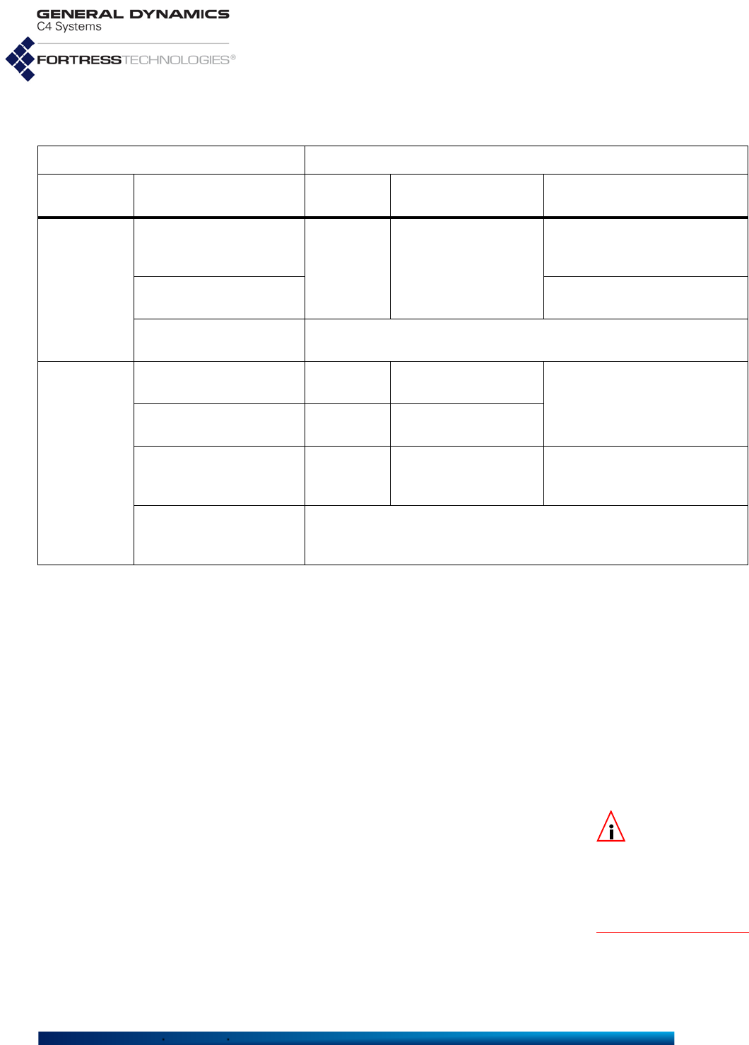
Fortress ES-Series CLI Guide: Networking and Radio Configuration
98
Configuring VLANs on the Mesh Point typically requires you to:
1Define one or more new VLANs on the Mesh Point’s
Active VLAN Table by specifying an associated VLAN ID
and IPv4 address for each. If the IPv4 address is not
specified, it defaults to
Not Configured
.
2For each new VLAN, configure one or more of the Mesh
Point’s network interface(s) as VLAN access ports by
specifying the associated VLAN ID and ensuring that
SwitchingMode is set to
Access
. Untagged frames
received on a VLAN access port are associated with the
interface’s VLAN ID and forwarded only to other access
ports on the same VLAN and to the trunk port.
NOTE: In
Enabled
VLAN Mode, there
is only one VLAN trunk
per Mesh Point, defined
by the Mesh Point’s
Active VLAN Table and
used by all
Trunk
ports.
3Configure one or more trunk ports to carry tagged frames,
where the VLAN tag identifies the VLAN with which the
frame is associated. If Fortress’s FastPath Mesh is used for
bridging, every FP Mesh Core port must be configured as a
VLAN trunk port. This parameter is set automatically during
BSS configuration and is enforced during Ethernet port
configuration.
4If Fortress’s FastPath Mesh is used for bridging and the
Mesh Point is subscribed to one or more multicast group(s),
you must associate each multicast group subscription with
Table 3.10 VLAN Traffic Handling on the Mesh Point
received traffic VLAN traffic handling
interface
Switching Mode VLAN tagging on ingress internal on egress
Access
untagged
accept tag w/ ingress interface
Default VLAN ID
tag = egress interface
Default VLAN ID: send
untagged
tag = ingress interface
Default VLAN ID tag ≠ egress interface
Default VLAN ID: drop
tag ≠ ingress interface
Default VLAN ID drop
Trunk
untagged accept tag w/ ingress interface
Default VLAN ID send untagged
tag = ingress interface
Default VLAN ID accept preserve tag
as received
tag ≠ ingress interface
Default VLAN ID and
is in Active VLAN Table accept preserve tag
as received send tagged as received
tag ≠ ingress interface
Default VLAN ID and is
not in Active VLAN Table drop
Fortress ES-Series CLI Guide: Networking and Radio Configuration
99
the VLAN used for multicast traffic by subscribed FPMPs
(described in Section 3.2.2).
5Enable VLANs on the Mesh Point.
When FastPath Mesh is used for bridging, the Mesh Point can
support up to eight VLANs, in Enabled VLAN Mode. When
BridgingMode is
Off
, the Mesh Point can support up to 48
VLANs, in Enabled VLAN Mode.
NOTE: Layer 2 dis-
covery protocols
must also be turned off
on any 3rd-party net-
work AP. Bridging loop
detection is incompati-
ble with VLAN transla-
tion, which is intended
to support an intention-
al loop in the L2 switch.
3.11.0.0.2 Translate VLAN Mode
You can set VLAN Mode to Translate only when the Mesh
Point’s global bridging Mode is Off. Translate VLAN Mode is
incompatible with FastPath Mesh (the default) and STP bridging
link management.
In Translate VLAN Mode, pairs of encrypted-side and clear-
side VLAN IDs are used to map packets with matching VLAN
ID tags between encrypted and clear VLANs on the Mesh
Point. Each such VLAN pair therefore constitutes a VLAN Map.
When a packet tagged with a VLAN ID that matches the
Encrypted Side VLAN ID of a VLAN Map is received on any
encrypted interface, the Mesh Point re-tags the packet with the
VLAN Map’s Clear Side VLAN ID as it passes the packet to any
clear interface. Likewise, when a packet is received on any
clear interface with a VLAN ID tag that matches the Clear Side
VLAN ID of a configured VLAN Map, the packet is re-tagged
with the Encrypted Side VLAN ID as it is passed to any
encrypted interface.
NOTE:
Any num-
ber of VLAN
trunks can be config-
ured on a Mesh Point in
Translate
VLAN
Mode
.
In this way VLAN ID-tagged packets can be passed in either
direction between VLANs on the Mesh Point’s clear and
encrypted interfaces as their VLAN ID tags are translated
accordingly. VLAN user-priority tags are preserved during
VLAN translation.
You can also configure a VLAN map (
vlanmap
), in which the
same VLAN ID is configured as the Encrypted Side VLAN ID
and the Clear Side VLAN ID, causing packets with matching
VLAN ID tags to pass between the Mesh Point’s encrypted and
clear interfaces without VLAN translation.
NOTE:
There is no
need for
VLAN
Map
s to be associated
with specific interfaces.
When the Mesh Point is in Translate VLAN Mode, an
incoming packet will be dropped, rather than forwarded from
clear to encrypted or encrypted to clear, if there is no VLAN
map with a matching VLAN ID configured for it.
VLAN IDs 1 through 4094 (inclusive) can be used in VLAN
maps. Note, however, that VLAN ID 1 is the default
Management VLAN ID. The VLAN IDs you configure in
translation maps must be present in the Mesh Point’s Active
VLAN ID Table (described in Section 3.11.1, below).
VLAN translation maps may not overlap: a given VLAN ID can
be used in only one VLAN map in the Mesh Point’s
vlanmap

Fortress ES-Series CLI Guide: Networking and Radio Configuration
100
table (although it can be used twice in the same map, as noted
above).
Observe the currently configured VLAN maps with show
vlanmap:
#
show vlanmap
Map Name Clear Vlan ID Encrypted Vlan ID
vlan12 12 2012
vlan11 11 2011
vlan10 10 10
Before you create VLAN translation maps, add the VLAN IDs
you will include in those maps to the Mesh Point’s Active VLAN
Table, as described in Section 3.11.1, below.
Create VLAN translation maps with the add vlanmap
command:
#
add vlanmap -n
<name>
-vc
<clearVLANID>
-ve
<encryptedVLANID>
Specify
VLAN IDs 1–4094, inclusive, and not in use by another
VLAN map, but note the default Management VLAN ID is 1.
Once established, the VLAN map name cannot be changed.
Use the name, with the -n switch, to identify the map for
update or deletion.
Update VLAN translation maps with the update vlanmap
command:
#
update vlanmap -n name -vc
<clearVLANID>
-ve
<encryptedVLANID>
You can delete a specified VLAN map or all configured VLAN
maps with the del command:
#
del vlanmap -all|-n name
3.11.1 Global VLAN Settings
Use set vlan to configure or update the Management VLAN
ID on the Mesh Point:
# set vlan -mode enabled|disabled|translate -mid 1–4094
Mode determines whether VLAN functionality is
Enabled
,
Translate or
Disabled
(the default). (VLAN Mode options are
described above.)
The mid setting identifies the management VLAN. VlanId
1
is
specified as the default Management VLAN ID and associated
with the current IPv4 address of the Mesh Point’s management
interface.
The Management VLAN ID must specify the VLAN associated
with the IPv4 address of the Mesh Point’s management
interface (refer to Section 3.9) in order for the Mesh Point to
remain accessible at its current IPv4 address. In the event of a

Fortress ES-Series CLI Guide: Networking and Radio Configuration
101
mismatch between the IPv4 address associated with the
Management VLAN ID and that of the Mesh Point’s
management interface, you can restore remote management
access to the Mesh Point only by reconfiguring it via a direct
physical connection to its Console port.
Additionally, when VLANs are enabled, the Mesh Point’s
internal DHCP and DNS services (described in Section 3.8) are
accessible only in the management VLAN. The Mesh Point will
not provide DHCP and DNS services on VLANs other than the
one associated with the Management VLAN ID.
Use add vlan to include additional VLANs in the Active VLAN
Table:
# add vlan -id 1–4094 -ip
<IPv4Addr>
-nm
<subnetMask>
NOTE: VLAN IDs
0 and 4095 are
reserved for internal
use.
The -id switch specifies a VLAN ID number, from 1–4094,
inclusive, for the VLAN.
The -ip switch associates the VLAN with a specific Unicast
IPv4 address. Alternatively, you can associate the VLAN with
an IP Address of 0.0.0.0. This will prevent IGMP queries from
being sent on the VLAN, in which cases IPv4 multicast
listeners on the VLAN may not be automatically discovered.
VLANs configured in this manner will appear as Not
Configured in show vlan.
Use the -nm switch to enter the IPv4 subnet mask associated
with this VLAN.
To change the IP address associated with a VLAN, use
update:
# update vlan -id
<vlanID>
-ip
<IPv4Addr>
-nm
<subnetMask>
View the current VLAN configuration with show:
> show vlan
Mode: enabled
Management VLAN: 1
[ACTIVE VLAN ID TABLE]
ID IPv4 Address IPv4 Subnet Mask
-- ------------ ----------------
1 192.168.1.6 255.255.255.0
2 Not Configured 255.255.255.0
3 Not Configured 255.255.255.0
[VLAN STATISTICS]
ID EncryptRx EncryptTx ClearRx ClearTx KeyExchangeRx KeyExchangeTx WllsRx WllsTx VlanMgmt
-- --------- --------- ------- ------- ------------- ------------- ------ ------ --------
1 0 0 142 35 0 0 0 0 0
2 0 0 0 0 0 0 0 0 0
3 0 0 0 0 0 0 0 0
Delete one VLAN or all VLANs from the Mesh Point
configuration by ID number with del vlans:
# del vlan -id
<vlanID>|
all

Fortress ES-Series CLI Guide: Networking and Radio Configuration
102
You can also have a new VLAN automatically added to the
table by specifying a VLAN ID not yet present on the table for
one of the Mesh Point’s Ethernet ports or radio BSSs (refer to
Section 3.11.2 below). VLAN IDs can be associated with IPv4
addresses, however, only through the Active VLAN Table
controls.
Changes to the Active VLAN Table take effect immediately.
You must be logged on to an
administrator
-level account to
change configuration settings (refer to Section 2.2).
3.11.2 Network Interface VLAN Settings
Each of the Mesh Point’s Ethernet ports and each BSS
configured on its radio(s) can be associated, by VlanID, with a
particular VLAN and configured as a VLAN
Trunk
or
Access
port.
When an Ethernet port or BSS on the Mesh Point is configured
as a VLAN trunk interface, it can be configured to carry all
VLANs or to filter which VLANs can use the interface. By
default, trunk interfaces are configured to allow all VLANs
(AllowAll
Y
).
All of the Mesh Point’s Ethernet ports have a default VLAN
SwitchingMode of
Access
and a default VlanId of
1
.
A default VlanId of
1
is also supplied during the creation of
new wireless interfaces. A radio BSS’s default VLAN
SwitchingMode depends on whether the interface is
configured to perform network bridging. When EnableWDS is
y
,
the VLAN Switching Mode is fixed on
Trunk
. When EnableWDS
is
n
, the default VLAN SwitchingMode is
Access
and the setting
is user configurable.
The Mesh Point’s Ethernet port VLAN Switching Mode and
Default VLAN ID settings are covered in Section 3.9. These
settings on radio BSSs are described in Section 3.4.9.
3.11.3 VLANs and FastPath Mesh
NOTE:
Translate
VLAN Mode is
incompatible with Fast-
Path Mesh bridging.
When VLANs are Enabled in FastPath Mesh bridging
deployments, some additional considerations apply.
3.11.3.0.1 FP Mesh networks have an upper limit of eight VLANs.
Although up to 48 VLANs can be present on the Active VLAN
Table and no lower maximum is enforced, Fortress generally
advises that no more than eight total VLANs be configured in
FP Mesh bridging deployments.
If your FastPath Mesh network requires a larger number of
VLANs, consult Fortress Technical Support.

Fortress ES-Series CLI Guide: Networking and Radio Configuration
103
3.11.3.0.2 FP Mesh Core interfaces must be VLAN trunk ports.
The requirement that only VLAN trunk ports can serve as FP
Mesh Core interfaces is enforced for wireless interfaces: The
same setting that configures a radio BSS to provide wireless
bridging also controls whether it will serve as an FP Mesh Core
or Access interface. Bridging interfaces are FP Mesh Core
interfaces by definition. Therefore, if the Meshif setting is
core
,
the interface’s VLAN SwitchingMode must be
Trunk
(refer to
Section 3.2.2).
3.11.3.0.3 FP Mesh multicast group subscriptions must specify a VLAN.
In addition to the interface and MAC/IP address of the multicast
group, each multicast group subscription on the Mesh Point
must specify by VLAN ID the correct VLAN to use for multicast
traffic (refer to Section 3.2.2).
3.11.3.0.4 FP Mesh NMPs are provided internal DHCP and DNS services
only in the management VLAN.
The DHCP and DNS services internal to the Mesh Point and
provided virtually configuration-free for Non-Mesh Points in
FastPath Mesh deployments (refer to Section 3.2.2) are
available only in the management VLAN (described in Section
3.11.1). An NMP that is not in the management VLAN will not
be able to use these services. For example, an NMP attached
to a VLAN access port whose default VLAN is not the
management VLAN will not be able to use these services.
3.12 ES210 Mesh Point Serial Port Settings
The serial port on the front panel of the ES210 Mesh Point is
configured by default to be used for Console port access to the
Mesh Point CLI.
On the ES210 Mesh Point, you can reconfigure the serial port
to instead connect the Mesh Point to an external third-party
Serial Sensor, or another serial device.
When the Serial Sensor is
Enabled
, the serial port behaves like
a serial terminal server, passing data between the specified
TCP (Transmission Control Protocol) port and the device
connected to the serial port. Serial data can be accessed using
telnet ip_addr tcp_port, with no options.
Only one TCP connection at a time is permitted to the Serial
Sensor TCP port. The ES210 Mesh Point can send data from
and to the connected serial device over any of the Mesh Point’s
wired or wireless interfaces, under the security provisions
configured for the interface and on the Mesh Point overall.

Fortress ES-Series CLI Guide: Networking and Radio Configuration
104
3.12.1 Configuring the Serial Port NOTE: You must
reboot the Mesh
Point in order to change
the function of the
ES210 serial port.
Enabling the serial sensor disables the serial port for Mesh
Point CLI access. The Mesh Point CLI remains accessible by a
terminal emulation application over an SSH2 (Secure Shell 2)
network connection, provided SSH access is
on
(the default;
refer to Section 4.1.13).
Use set sensor to enable and configure the ES210 Mesh
Point’s serial port to connect to an external serial device:
# set sensor -enable y|n -baud 300|600|1200|2400|4800|9600|19200|38400 -parity none|even|odd
-stopBits 1|2 -port
<5000..65534>
CAUTION:
Enabling the
Serial Sensor function
on the ES210 Mesh Point
disables management
access through the serial
port.
Enable (
y
) or disable (
n)
the serial sensor function. Disabling
the Serial Sensor function re-enables the port’s Mesh Point CLI
Console function and automatically returns serial port settings to
the correct values for the Mesh Point CLI (baud rate:
9600
,
parity:
none
, stop bits:
1
).
Specify the Baud Rate (-baud), the number of bits per second
for the serial connection at
300, 1200, 2400, 4800, 9600
(the
automatic setting for the Console port),
19200
, or
38400
(the
default when sensor is
Enabled
).
Parity specifies whether the parity bit used for error checking
results in an
Even
or
Odd
number of bits per byte or, with a
setting of
None
(the default), that no parity bit should be added.
StopBits specifies whether the port should use a stop bit of
1
(the default) or 2.
Specify the TCP port (-port) for the serial interface. Port
values between
5000
and
65534
are valid; the default is port
5001
.
The serial port always uses 8 data bits per character and no
hardware or software flow control.
After entering the configuration information, you must reboot
the ES210 Mesh Point to change the serial port function (refer
to Section 5.2).
You can view the current serial sensor settings for the Mesh
Point:
# show sensor
Serial Sensor Settings
Enabled: no
Baud Rate: 38400
Parity: none
Stop Bits: 1
Port: 5001

Fortress ES-Series CLI Guide: Networking and Radio Configuration
105
Restoring the ES210 Mesh Point’s factory default configuration
restores the serial port to the default Mesh Point CLI Console
function (refer to Section 5.5).
3.12.2 Resetting the Serial Port
When the ES210 Mesh Point is enabled for and connected to
an external serial device, you can manually restart the serial
port’s TCP session with reset sensor.
# reset sensor
Resetting the serial port has no effect when the Serial Sensor
function is disabled.
3.13 Mesh Viewer Protocol Settings
Fortress offers a stand-alone viewer application called the
Mesh Viewer to monitor the status and connections of the
FastPath Mesh network. Mesh Points provide information
about their status and health using the proprietary protocol
Mesh Viewer Protocol (MVP). The CLI allows configuration of
several parameters relating to the MVP.
View the current MVP settings with show mvp:
# show mvp
Mesh Viwer Manager is running
MVP packet transmission is enabled
MVP packet transmission interval: 30 secs
Configured MVP port numbers
MVP IPv6 multicast UDP port: 4949
MVP client TCP port: 4949
Use set mvp to alter MVP settings:
# set mvp -serviceUp Y|N -enable Y|N -interval 5-300 -udpport 1042, 4949, 49152-65535 -tcpport
1042, 4949, 49152-65535
NOTE: PORT 4949
should only be
used in stand-alone
mesh networks (meshes
with no connection to
the Internet).
The -serviceUp switch starts or stops the MVP manager
process. The default is to start the process. Configuring the
process off saves CPU cycles if there is no need for the MVP (if
there is no Mesh Viewer running).
The -enable switch enables or disables sending out MVP
packets. The default is for nodes to send MVP packets.
Configuring MVP packet sending off saves CPU cycles and
may save bandwidth.
The -interval switch controls the time interval between MVP
packet transmission. The value is in seconds from 5 seconds to
300 seconds (5 minutes). The default is 30 seconds. A smaller
value will provide more up-to-date information the Mesh
Viewer, but at the cost of CPU cycles and bandwidth.

Fortress ES-Series CLI Guide: Networking and Radio Configuration
106
The -udpport switch chooses the UDP port out which the
Mesh Point will send its MVP packets to the MVP Listener
Mesh Point within the mesh network, or to the Mesh Viewer
itself, if the Mesh Viewer is directly connected to a mesh
network access interface.
The -tcpport switch chooses the TCP port on which the MVP
Listener Mesh Point will listen for incoming TCP connections
from the Mesh Viewer, which may be on the mesh network or
many be on a remote network connected to the mesh. The
MVP Listener Mesh Point will then forward all MVP packets it
receives from other Mesh Points to the Mesh Viewer, along
with its own MVP packets.


Fortress ES-Series CLI Guide: Network Security, Authentication and Auditing
109
Chapter 4
Network Security, Authentication and Auditing
4.1 Fortress Security Settings
NOTE:
Fortress
MSP is not sup-
ported on an ES210 Mesh
Point in
Station Mode
(refer to Section 3.4.10).
The CLI provides controls for various aspects of the Mesh
Point’s overall network security provisions: Fortress MSP
(Mobile Security Protocol) functions including key
establishment, data encryption and network Access ID; FIPS
operation; global session timeouts; and several additional
management and network access settings.
A basic set of security settings can be viewed through the
Mesh Point CLI with show crypto:
# show crypto
CryptoEngine:AES256
ReKeyInterval:14400 seconds (4h)
Key Beacon Interval:30 seconds
DHsize:1024,2048
Compression:On
Legacy:Off
The Security settings you can view through show crypto are
configured through the
set crypto
command, using various
switches, as described in the relevant subsections below.
The Access ID and passwords cannot be displayed for security
reasons.
Several security settings have their own show and set
commands, as described in their respective subsections.
4.1.1 Operating Mode
The Fortress Mesh Point can be operated in either of two
modes: Normal or FIPS (the default).
The rigidly enforced administrative requirements of FIPS
operating mode are required by deployments and applications
that must comply with the Federal Information Processing
Standards (FIPS) for cryptographic modules. However, the
high levels of security that can be implemented in Normal
operating mode generally meet or exceed the needs of virtually
all networked environments that are not required to comply
with FIPS.
Fortress ES-Series CLI Guide: Network Security, Authentication and Auditing
110
NOTE: Contact
your Fortress rep-
resentative for up-to-
date information on the
Mesh Point’s FIPS vali-
dation status.
FIPS operating mode in the current version of Mesh Point
software may still be in the process of being validated as
compliant with FIPS 140-2 Security Level 2. These Federal
standards enforce security measures beyond those of Normal
operating mode, the most significant of which include:
Only a designated Crypto Officer, as defined by FIPS, may
perform administrative functions on the Mesh Point and its
Secure Clients. (The preconfigured
administrator
-level
admin account corresponds to the FIPS Crypto Officer role;
refer to Section 2.2.3.)
If the Mesh Point encounters a FIPS Error condition, it
shuts down and reboots, running FIPS self-tests as a
normal part of boot-up. If FIPS self-tests pass, the Mesh
Point will return to normal operation. If FIPS self-tests fail,
before any interfaces are accessible, the Mesh Point will
again reboot. If the Mesh Point is unable to pass power-on
self-tests, it will cycle perpetually through this reboot
process. In this case, you must return the Mesh Point to
your vendor for service or replacement.
DH-512 and DH-1024 key establishment (Section 4.1.5)
are no longer FIPS 140-2-compliant and are therefore not
compatible with FIPS operating mode.
NOTE: Only
devices config-
ured on the Mesh Point
to pass clear text on
encrypted interfaces are
permitted to do so, even
when encrypted zone
cleartext is enabled.
Regardless of the current operating mode, the Mesh Point can
be configured to allow unencrypted data on encrypted
interfaces by enabling cleartext traffic in the encrypted zone
(refer to Section 4.1.9). In FIPS terminology, this indicates that
the Mesh Point is in Bypass Mode (BPM), as selectively
permitted clear text can pass, along with any encrypted traffic,
on encrypted interfaces.
The current operating mode can be determined by the
command prompt: FIPS; for FIPS mode, or > or # for Normal
operating mode.
The show fips command provides the same information, as
well as a status indicator:
# show fips
State:On
Status:OK
Possible FIPS Status values depend on the current FIPS
State.
When the FIPS State is On:
OK - FIPS tests passed: FIPS tests have either never
failed or have not failed since the last time set fips
retest was executed.
Test in progress - FIPS tests are currently running.
When the FIPS State is Off:

Fortress ES-Series CLI Guide: Network Security, Authentication and Auditing
111
OK - has no meaning with regard to FIPS tests, which
are run regardless of the FIPS State, but can fail
without affecting the reported FIPS Status. When FIPS
is Off, the Mesh Point will continue to pass traffic
regardless of FIPS test results, and the FIPS Status is
always OK.
FIPS operating mode, which complies with Federal Information
Processing Standards 140-2, is the default mode of operation.
The Fortress Mesh Point’s Normal operating mode does not
comply with FIPS.
NOTE: In FIPS
operating mode
the command prompt is
<hostname>FIPS>
(for view-only accounts)
or <hostname>FIPS#
(for administrator-
level accounts).
Change between operating modes with the set fips
command. To turn FIPS operating mode on:
# set fips on
To place the Mesh Point in Normal operating mode, turn FIPS
operating mode off:
FIPS# set fips off
You must be logged on to an
administrator
-level account to
change configuration settings (refer to Section 2.2).
4.1.2 FIPS Settings
View complete current FIPS tests settings and statistics with
show fips -v:
FIPS> show fips -v
State:On
Status:OK
TestControl:No periodic tests
RunInterval:86400
ReSeedInterval:86400
RunRngContinuousTests:Yes
Last Run Succeeded:Yes
PrngPostFail:No
SoftCryptHashFailCT:0
SoftCryptCompressFailCT:0
SoftCryptEncryptFailCT:0
SoftCryptRngFailCT:0
SoftCryptMiscFailCT:0
FPCDDuplicateIVFailCT:0
FPCDTrngFailCT:0
FPCDPrngFailCT:0
ECDHKeyGenFailCT:0
OpenSSLFailCT:0
PktEncryptFailCT:0
PktDecryptFailCT:0
BadPktDecryptFailCT:0
SuiteBPktEncryptFailCT:0
SuiteBPktDecryptFailCT:0
SuiteBBadPktDecryptFailCT:0
CCMPPktEncryptFailCT:0
CCMPPktDecryptFailCT:0
CCMPBadPktDecryptFailCT:0
BypassGuestCreateFailCT:0

Fortress ES-Series CLI Guide: Network Security, Authentication and Auditing
112
BypassBroadcastFailCT:0
BypassUnknownDAFailCT:0
BypassHostToGuestFailCT:0
BypassHostToClientFailCT:0
BypassRcvClrFromClientFailCT:0
BypassCCMPSecureFailCT:0
BypassCCMPNonSecureFailCT:0
PktEncryptTimeoutCT:0
PktDecryptTimeoutCT:0
BadPktDecryptTimeoutCT:0
SuiteBPktEncryptTimeoutCT:0
SuiteBPktDecryptTimeoutCT:0
SuiteBBadPktDecryptTimeoutCT:0
CCMPPktEncryptTimeoutCT:0
CCMPPktDecryptTimeoutCT:0
CCMPBadPktDecryptTimeoutCT:0
BypassGuestCreateTimeoutCT:0
BypassBroadcastTimeoutCT:0
BypassUnknownDATimeoutCT:0
BypassHostToGuestTimeoutCT:0
BypassHostToClientTimeoutCT:0
BypassRcvClrFromClientTimeoutCT:0
BypassCCMPSecureTimeoutCT:0
BypassCCMPNonSecureTimeoutCT:0
KeyGenCryptoFailCT:0
LastFailedRunTS:0
FailedRunCT:0
LastCompleteRunTS:Sun May 17 08:23:38 2015
CompleteRunCT:183
NOTE: In FIPS
operating mode,
the Mesh Point stops
passing traffic in the
encrypted zone upon
any FIPS test failure and
until all FIPS tests are
again passed.
You can display just the first two lines of the show fips -v
output by omitting the -v switch.
The Mesh Point runs a number of self-tests described in FIPS
140-2, (Federal Information Processing Standards’ Security
Requirements for Cryptographic Modules).
FIPS tests run—and self-test failures are logged—regardless
of whether it is in FIPS or Normal operating mode. When the
Mesh Point is in FIPS operating mode, it will additionally shut
down and reboot upon the failure of any FIPS self-test, as
required by FIPS 140-2 (refer to Section 4.1.1).
FIPS tests can be automatically triggered or manually
executed, and automatic FIPS testing is always enabled,
regardless of operating mode or FIPS settings. Automatic test
triggers include any security-related change to the Mesh
Point’s configuration (deleting a user, for example, or changing
the re-key interval).
Use the set fips command to change FIPS test settings and
to manually initiate FIPS self-tests.
Run FIPS self tests manually with set fips:
FIPS# set fips retest

Fortress ES-Series CLI Guide: Network Security, Authentication and Auditing
113
As required by FIPS 140-2, if a FIPS test fails, the failure
persists—through reboots and software upgrades—until the
Mesh Point again passes the full battery of FIPS tests. In FIPS
operating mode, If the Mesh Point fails a FIPS test, it
automatically reboots. If the failure persists through the boot
cycle, the Mesh Point continues to reboot until the test passes
or the Mesh Point is taken out of service.
In addition to the FIPS tests triggered regularly on the Mesh
Point, you can configure additional, periodic FIPS testing, with
set fips:
FIPS# set fips periodic|noperiodic
Periodic FIPS testing is disabled by default (
noperiodic
).
When periodic tests are enabled, they run at the FIPS-test run-
interval specified using set fips with the -r switch. The
default is 86,400 seconds, or 24 hours.
You can also configure the interval at which the random
number generator is reseeded using set fips with the -s
switch. The default is 86,400 seconds, or 24 hours.
FIPS# set fips -r
<RunIntervalSeconds>
-s
<SeedIntervalSeconds>
With set fips you can also configure whether the Mesh
Point’s random number generator test will be run routinely (it is
enabled by default):
# set fips rngtest
RngContinuousTests? [N|Y]
This command can be run only interactively. The Mesh Point
CLI displays
RngContinuousTests?
and you can enter your
selection—or leave the field blank and the setting unchanged—
and strike Enter↵.
The Mesh Point CLI returns [OK] when settings are
successfully changed. You cannot turn off FIPS random
number generator tests when the Mesh Point is in FIPS
operating mode.
You must be logged on to an
administrator
-level account to
change configuration settings (refer to Section 2.2).
4.1.3 MSP Encryption Algorithm
The encryption algorithm determines how the Mesh Point
encodes data. All Secure Clients logging on through the
Fortress Mesh Point, and other Mesh Points with security
associations to this one, must use the same encryption
algorithm.
View the encryption algorithm (among other security settings)
in effect on the Mesh Point with show crypto (shown in Section
4.1).

Fortress ES-Series CLI Guide: Network Security, Authentication and Auditing
114
Select the encryption algorithm that the Mesh Point will allow
Secure Clients and other Fortress controller to use with
set
crypto
:
# set crypto -e AES128|AES192|AES256
For information on setting encryption algorithms on Secure
Clients, refer to the Fortress Secure Client User Guide.
The default encryption algorithm is AES256.
You must be logged on to an
administrator
-level account to
change configuration settings (refer to Section 2.2).
4.1.4 Encrypted Data Compression
View the encrypted data compression setting (among other
security settings) in effect on the Mesh Point with show crypto
(shown in Section 4.1).
Data compression on the Mesh Point is configured with set
crypto:
# set crypto -comp on|off
Compression is turned on by default.
All Mesh Points in a given network must be configured to use
the same encrypted data compression setting, in order for
them to be able to communicate.
The Mesh Point CLI returns
OK
when settings are successfully
changed.
NOTE: Separate
multicast and
broadcast packets are
sent for each config-
ured key group. To
maximize wireless
throughput, limit the
number you select.
4.1.5 MSP Key Establishment
Select the method of key establishment the Mesh Point will
allow Secure Clients and other Fortress devices to use with
set crypto, as follows:
# set crypto -dh 512|1024|2048|suiteB
You can specify any of three supported Diffie-Hellman groups
(DH-2048 is the default selection). When operating the Mesh
Point in FIPS mode (Section 4.1.2), you cannot use DH-512
or DH-1024 key establishment, because the smaller Diffie-
Hellman group moduli are no longer compliant with FIPS 140-2
Security Level 2.
NOTE: DH-512 key
establishment can-
not be selected when a
32-digit Access ID (Sec-
tion 4.1.16) is used.
When it has been licensed on the Mesh Point (Section 5.6),
you can also select the NSA (National Security Agency) Suite
B-compliant elliptic curve Diffie-Hellman key establishment.
The set crypto -dh command is not additive; it overwrites
existing settings.
Fortress ES-Series CLI Guide: Network Security, Authentication and Auditing
115
NOTE: Secure Cli-
ent versions ear-
lier than 3.1 support
only DH-512 key estab-
lishment.
A Secure Client logging on to the Mesh Point must use a key
establishment setting present in the Mesh Point’s configuration.
For information on configuring key establishment on Secure
Clients, refer to the Fortress Secure Client User Guide.
The Mesh Point CLI returns
OK
when settings are successfully
changed.
4.1.6 MSP Re-Key Interval
The re-keying interval is the length of time between new keys
issued by the Mesh Point. View the re-keying interval (among
other security settings) in effect on the Mesh Point with show
crypto (shown in Section 4.1).
The re-keying interval in effect between the Fortress Mesh
Point and its Clients or other Mesh Points is set, in values
between 1 and 24 hours, with the set crypto command:
NOTE:
The user can
choose to disable re-
keying ONLY if FIPS mode
is disabled, by choosing a
re-keying interval of 0.
# set crypto -t
<hrs>
The default re-keying interval is 4 hours.
You must be logged on to an
administrator
-level account to
change configuration settings (refer to Section 2.2).
4.1.7 Key Beacon Interval
In order to maintain active, secure connections to other
Fortress devices on the Fortress-secured network, the Mesh
Point transmits network key beacons at regular, user-
configurable intervals. View the key beacon interval (among
other security settings) in effect on the Mesh Point with show
crypto (shown in Section 4.1).
The Mesh Point’s beacon interval is set in seconds between 0
and 3000, inclusive (a setting of 0 (zero) disables the beacon).
It is configured with the set crypto command using the -b
switch:
# set crypto -b
<secs>
The default beacon interval is 30 seconds.
You must be logged on to an
administrator
-level account to
change configuration settings (refer to Section 2.2).
4.1.8 Fortress Legacy Devices
You can configure the Mesh Point to support legacy devices.
View the current legacy device setting (among other security
settings) in effect on the Mesh Point with show crypto (shown
in Section 4.1).
Enable or disable support for legacy devices with set crypto:
# set crypto -legacy on|off
You must be logged on to an
administrator
-level account to
change configuration settings (refer to Section 2.2).

Fortress ES-Series CLI Guide: Network Security, Authentication and Auditing
116
4.1.9 Encrypted Zone Cleartext Traffic
By default, the Mesh Point does not allow cleartext traffic to
pass on encrypted interfaces.
In order for configured cleartext devices (access points and/or
Trusted Devices) to be permitted access on an encrypted
interface, cleartext must be turned
on
.
Disabling cleartext traffic on encrypted interfaces after AP
management rules or Trusted Devices have been configured
will not remove them from the configuration. Because these
cleartext devices cannot decrypt encrypted traffic, however, the
Mesh Point will not be able to communicate directly with them
until cleartext traffic is permitted on encrypted interfaces.
View the current cleartext setting on the Mesh Point with the
show command:
> show cleartext
On
Enable/disable cleartext traffic in the encrypted zone with the
set command:
# set cleartext on|off
You must be logged on to an
administrator
-level account to
change configuration settings (refer to Section 2.2).
4.1.10 Encrypted Zone Management Settings
Access to the Mesh Point’s management interface via an
encrypted interface on the Mesh Point can be globally
controlled. When encrypted management access is globally
allowed, you can additionally permit authorized cleartext
devices on encrypted interfaces to manage the Mesh Point.
4.1.10.1 Encrypted Interface Management Access
By default, the Mesh Point allows the management interface to
be accessed on encrypted non-bridging interfaces by local
Secure Client devices or through remote Fortress devices or
network bridging links. View the current management access
setting for encrypted interfaces with the show command:
> show clientmanagement
On
Encrypted interface client management applies to any
connection to an encrypted interface on the current Mesh
Point, including:
connections through a remote Fortress Mesh Point
bridging links between networked Fortress Mesh Points
authorized cleartext devices when clearmanagement
(below) is enabled.
local Fortress Secure Client connections

Fortress ES-Series CLI Guide: Network Security, Authentication and Auditing
117
Client management is enabled (on) by default.
If encrypted interface client management is disabled (off), you
will be able to manage the Mesh Point only through a clear
interface (or through the serial Console port).
Enable/disable client management access on the Mesh Point’s
encrypted interfaces with the set command:
# set clientmanagement on|off
You must be logged on to an
administrator
-level account to
change configuration settings (refer to Section 2.2).
4.1.10.2 Authorized Cleartext Device Management Access NOTE:
If either
clientmanage-
ment or cleartext
is
off
, clear devices on
encrypted interfaces will
not be able to manage
the Mesh Point, regard-
less of the
clearman-
agement
setting.
By default, the Mesh Point blocks management access by
authorized cleartext devices on encrypted interfaces. View the
current setting with the show command:
> show clearmanagement
Off
If management access via encrypted interfaces is globally
permitted (see clientmanagement, above), you can enable
management access for authorized cleartext devices on
encrypted interfaces with the set command:
# set clearmanagement on|off
You must be logged on to an
administrator
-level account to
change configuration settings (refer to Section 2.2).
4.1.11 Authorized Wireless Client Management
Settings
By default, the Mesh Point allows management access by
authorized wireless clients in the clear zone. View the current
setting with the show command:
> show wifimanagement
On
The management access for authorized wireless clients in the
clear zone can be configured with the set command:
# set wifimanagement on|off
You mut be logged on to an
administrator
-level account to
change configuration settings (refer to Section 2.2).
4.1.12 Turning Mesh Point GUI Access Off and On
Browser connections to the Mesh Point’s management
interface are secured via https (Hypertext Transfer Protocol
Secure). GUI access can be authenticated via the self-signed
X.509 digital certificate automatically generated by the Mesh
Point for use by SSL (Secure Socket Layer) and present by
default in the local certificate store. You can also import and
select a different certificate for the Mesh Point's SSL function
(refer to Section 4.2.2).

Fortress ES-Series CLI Guide: Network Security, Authentication and Auditing
118
You can turn off GUI access to the Mesh Point altogether by
disabling the user interface. The Mesh Point GUI is enabled by
default.
You can view the current GUI access setting with show gui:
> show gui
Status: On
SSL Private Key: ssl_auto_key
Require client certificate: no
Auto Logon client certificate: no
If you want to limit access to the Fortress Mesh Point
exclusively to the Mesh Point CLI, you can disable the Mesh
Point GUI, as follows:
# set gui off
To re-enable the Mesh Point GUI, enter:
# set gui on
You can use the -key switch to indicate or change the private
key and client certificate to use for SSL sessions:
# set gui -key
<keyname>
Use the -nokey switch to clear the encryption key currently in
use:
# set gui -nokey
If you want to require the GUI client to present a digital
certificate to be authenticated before being permitted access,
set
-requireClientCertificate
to
enabled
.:
# set gui -requireClientCertificate enabled
[OK] Note: You must restart the controller for client authentication changes to take effect.
Turn this functionality back off with the same command:
# set gui -requireClientCertificate disabled
[OK] Note: You must restart the controller for client authentication changes to take effect.
NOTE:
When SSO
is configured, if
the Mesh Point is also
configured to authenti-
cate with a RADIUS
server rather than with
local authentication, the
user must enter user-
name and password the
first time the certificate
Common Name user
tries to logon. This is
necessary in order to
populate the local
authentication cache.
As the prompt informs you, you must reboot the Mesh Point in
order to put a change to
-requireClientCertificate
into
effect: refer to Section 5.2.
If you want to automatically log in GUI users who have
presented a valid certificate, without requiring them to enter
user name and password, set -clientCertificateSignOn to
enabled:
# set gui -clientCertificateSignOn enabled
You must also require the GUI client to present a digital
certificate; -requireClientCertificate must be enabled if
-clientCertificateSignOn is enabled. This feature is most
useful when Common Access Cards (CAC) are used, but any
X509 client certificate may be used as long as the Common
Name (CN) contains the user name.

Fortress ES-Series CLI Guide: Network Security, Authentication and Auditing
119
The Mesh Point CLI returns
OK
when settings are successfully
changed.
You must be logged on to an
administrator
-level account to
change configuration settings (refer to Section 2.2).
4.1.13 SSH Access to the Mesh Point CLI
SSH2 (Secure Shell protocol 2) is enabled on the Mesh Point
by default. The Mesh Point does not support SSH1.
You can view the current SSH setting with show ssh:
> show ssh
EnableSsh: Y
Public Keys
---------
0 public keys configured
NOTE: Disabling
SSH prevents
remote access to the
Mesh Point CLI from
the network. With SSH
disabled you can access
the CLI only over a
direct connection to the
Mesh Point’s Console
port.
4.1.13.1 Disabling and Enabling SSH Access to the Mesh Point
CLI
To disable SSH, enter:
# set ssh off
You can disable SSH from a remote terminal session; however,
the SSH session will be dropped immediately upon execution
of the command.
To re-enable SSH, log in to the Mesh Point CLI (via a direct
connection to the Mesh Point’s Console port) and enter:
# set ssh on
You must be logged on to an
administrator
-level account to
change configuration settings (refer to Section 2.2).
4.1.13.2 Configuring Public Key Authentication
For more secure authentication, the Mesh Point provides the
capability to configure SSH to utilize Public Key Authentication
in addition to entering a username/password.
There are two ways to import the public key into the Mesh
Point.
The first way is to manually enter the contents of the SSH
public key. When the following command is executed, the user
will be prompted to enter the SSH public key information:
# import sshkey -name <SSHPublicKeyName>
The second way is to provide a URL to the SSH public key file:
# import sshkey -name <SSHPublicKeyName> -url <SSHPublicKeyURL>
The Mesh Point provides the capability to delete the SSH
public keys either all at once or by name.
To delete all the SSH public keys:

Fortress ES-Series CLI Guide: Network Security, Authentication and Auditing
120
# del sshkey -all
To delete a specific SSH public key:
# del sshkey -name <SSHPublicKeyName>
You must be logged on to an administrator-level account to
change configuration settings (refer to Section 2.2).
4.1.14 Blackout Mode NOTE: You can
also toggle the
Mesh Point’s Blackout
Mode in the Mesh Point
GUI (described in the
GUI Guide), and with
chassis controls on some
Mesh Point models
(covered in their respec-
tive Hardware Guides).
The Blackout Mode setting on the Fortress Mesh Point globally
turns all chassis LEDs on and off.
When Blackout Mode is Enabled, none of the Mesh Point’s
LEDs will illuminate for any reason—except for a single, initial
blink (green) of less than half a second, at the beginning of the
boot process in some models. When Blackout Mode is
Disabled (the default), the LED indicators function normally.
View the current blackout mode with show blackout:
> show blackout
On
Enable/disable blackout mode with the set command:
# set blackout on
[OK]
You must be logged on to an
administrator
-level account to
change configuration settings (refer to Section 2.2).
4.1.15 Allow Cached Credentials
When a device’s session times out, the device is required to
renegotiate encryption keys in order to reconnect to the
network. When the Mesh Point is configured to permit cached
authentication credentials (the default), Secure Clients are
allowed to transparently reauthenticate, without user
intervention. You can force Secure Client users to re-enter their
credentials whenever their sessions are reset by disabling the
cachedauth setting.
View the current cached credentials settings with show
cachedauth:
> show cachedauth
ClientReAuth: N
Enable/disable permission for Secure Clients to reauthenticate
with cached user credentials with set cachedauth:
# set cachedauth y|n
You must be logged on to an
administrator
-level account to
change configuration settings (refer to Section 2.2).
Fortress ES-Series CLI Guide: Network Security, Authentication and Auditing
121
4.1.16 Fortress Access ID
NOTE: Secure Cli-
ent versions ear-
lier than 3.1 support
only 16-digit Access
IDs.
The Access ID is a 16- or 32-digit hexadecimal ID that provides
network authentication for the Fortress Security System. It is
set with the set accessid command, as follows:
# set accessid
<16digithexid>
|
<32digithexid>
|random|default
-confirm
<16digithexid>
|
<32digithexid>
|random|default
NOTE: A 32-digit
Access ID cannot
be configured when
DH-512 key establish-
ment (Section 4.1.5) is
selected.
You can manually enter either a 16-digit or a 32-digit
hexadecimal Access ID of your own composition, or you can
elect to have the Mesh Point randomly generate a 32-digit
Access ID and display the result for you to record.
Regardless of how you establish the Mesh Point’s Access ID,
you must make a record of the Access ID at the same time that
you create it. For security purposes, once you have left the
screen on which it was initially established, the Access ID can
never again be displayed.
CAUTION: The
Access ID is dis-
played exactly once, at
its creation, after which
there is no way—in the
GUI or CLI—to discover
the Access ID config-
ured on the Mesh Point.
All Secure Clients logging on to the Mesh Point must be
configured to use the same Access ID as the Mesh Point. For
information on setting the Access ID on Secure Clients, refer to
the Fortress Mesh Point Software GUI Guide.
The default Access ID is represented by 16 zeros
(0000000000000000) or the word default, which when used
with the set accessid command will return to the Mesh Point’s
Access ID to its default setting.
The Mesh Point CLI returns
OK
when settings are successfully
changed.
You must be logged on to an
administrator
-level account to
change configuration settings (refer to Section 2.2).
4.2 Digital Certificates
The Mesh Point automatically generates a self-signed digital
certificate conforming to the X.509 ITU-T1 standard for a public
key infrastructure (PKI). This certificate and associated RSA
2048-bit public/private key pair are present in the Mesh Point’s
certificate management configuration and used for the Mesh
Point GUI by default.
4.2.1 Generating CSRs and Key Pairs
The generate csr command allows you to generate a PKCS
(Public Key Cryptography Standards) #10 certificate signing
request (CSR).
# generate csr -name
<CSRname>
-subject
<X.500 DN>
-newkey -type
rsa2048|ec256|ec384
1. International Telecommunication Union-Telecommunication Standardization Sector;
formerly, CCITT

Fortress ES-Series CLI Guide: Network Security, Authentication and Auditing
122
The -subject option is defined as X.500 Distinguished
Names and has to be a quoted string with the following format:
"/C=
<country>
/ST=
<state>
/O=
<organization>
/CN=
<commonname>
"
The -type option selects the algorithm and key length, in bits,
for the key pair to be generated for the CSR:
rsa2048 - (the default) RSA (Rivest, Shamir and Adleman)
2048-bit
ec256 - elliptical curve 256-bit
ec384 - elliptical curve 384-bit
The -newkey option allows you to generate a new public/
private key pair automatically while generating the CSR. If the
key pair already exists (see "generate keypair"), use the key
pair name as the CSRname and omit the -newkey option.
The generate keypair command allows you to generate a
public/private key pair.
generate keypair -name <Keyname> -type rsa2048|ec256|ec384
View current public or private key pairs with the show keypair
command:
# show keypair
Key Type Cert
----------------------------------- ------- ----
ssl_auto_key rsa2048 yes
You can delete a public/private key pair or all key pairs:
# del keypair -name <
KeyName
>|-all
4.2.2 Managing Local Certificates
The Mesh Point’s self-signed certificate, used by default for the
Mesh Point GUI, is automatically generated and always
present in the local certificate store.
View current certificates with the show certificate
command:
# show certificate
End User Certificates
---------------------
Name : ssl_auto_key
Hash : 86cef5bbcc57acf9b27613efff3697519ebc956db0b68191580b9b6c5d0e1cf1
Usage : ssl
Subject : CN=192.168.1.6, emailAddress=support@gdfortress.com
Issuer : C=US, ST=MA, O="Fortress Technologies", OU="Gateway Security",
CN="Fortress Technologies Certificate Authority", emailAddress=support@gdfortress.com
(cert=Not Available)
Valid as of : Sep 28 09:45:21 2012 GMT
Valid until : Oct 28 09:45:21 2012 GMT

Fortress ES-Series CLI Guide: Network Security, Authentication and Auditing
123
Append more to any show certificate command to scroll
through the output one page at a time, using Enter↵ or the
space bar to page down. When more is omitted, use Ctrl-C to
truncate multiple-screen command output.
View only a specific certificate with the -name switch:
# show certificate -name CACERT00000002
Name : CACERT00000002
Subject : C=US, O=U.S. Government, OU=DoD, OU=PKI, CN=DoD JITC Root CA 2
Issuer : C=US, O=U.S. Government, OU=DoD, OU=PKI, CN=DoD JITC Root CA 2 (ce
rt=CACERT00000002)
Valid as of : Jul 15 03:31:31 2005 GMT
Valid until : Jul 4 03:31:31 2030 GMT
You can opt to display abbreviated certificate information with
the -brief switch, or more complete certificate key information
than is displayed by default, with the -detail switch.
You can filter show certificate output to include only
-expired certificates, only -ca (Certificate Authority)
certificates, only -enduser certificates, or only those certificates
that have been validated by an -ocsp (Online Certificate Status
Protocol) responder.
4.2.2.1 Importing and Deleting Certificates
Various types of certificates, in PEM.ASN.1 DER or PKCS7
format, can be imported and installed on the Mesh Point.
If the certificate you are importing is not an end user certificate
(the default), you must specify its type, and you must configure
the parameters required for the type of certificate you are
importing:
End-user certificates (or certificate chains) are associated
with a public/private key pair used by the Mesh Point. You
must specify, with -key, the key pair/CSR (certificate
signing request) to associate with the certificate (or the first
certificate in a certificate chain).
# import certificate -key
<keypairCSR>
CA certificates are certificates associated with Certificate
Authorities that are trusted by the Mesh Point (a trusted
intermediate CA, a trusted root CA, or a chain of certificates
for multiple trusted CAs). You must specify a CA certificate,
with -ca. Use -url to configure the URL (full IP address or
domain name) for an LDAP (Light Directory Access
Protocol) server, and -ldapsb to specify (as the
distinguished name of the search base object) a starting
point for certificate retrieval searches of the LDAP directory.
# import certificate -ca -url
<LDAPsrvrURL>
-ldapsb
<searchBaseDN>

Fortress ES-Series CLI Guide: Network Security, Authentication and Auditing
124
Trusted OCSP Responder certificates are certificates (or
certificate chains of multiple certificates of one or more
trusted OCSP responders) associated with OCSP
responders from which the Mesh Point always accepts
signed OCSP responses. You must specify a trusted OCSP
responder certificate, with -ocsp. Use -url to configure the
standard http address (full IP address or domain name) of
the certificate server from which the certificate or certificate
chain being installed will be retrieved. Use -ldapattr to
specify whether the certificate attribute for retrieval is a CA
certificate, with ca, or an end user certificate, with user.
# import certificate -ocsp -url
<CertSrvrURL>
-ldapsb
<searchBaseDN>
-ldapattr ca|user
You can delete the entire contents of the Mesh Point certificate
store with -all, or all of those certificates that have -expired:
CAUTION: If you
delete the only
available certificate(s)
for the Mesh Point GUI’s
SSL connection, your
session will end and
you will not be able to
reconnect until, after a
brief delay, the default
self-signed SSL certifi-
cate has been automati-
cally restored.
# del certificate -all|-expired
You can also delete a specific certificate by -name. If the
certificate is a CA certificate, add the -ca switch. If it is the
certificate for a trusted OCSP responder, add -ocsp.
# del certificate -name <
CertificateName>
-ca -ocsp
You must be logged on to an
administrator
-level account to
change configuration settings (refer to Section 2.2).
4.2.2.2 Assigning Stored Certificates to Mesh Point Functions
Locally stored signed certificates can have any of three
applications on the Mesh Point, as indicated in the Usage
column of the show certificate output:
ssl - the Secure Socket Layer certificate is used by the
Mesh Point GUI to secure browser connections to the
management interface via https.
By default, the Mesh Point GUI uses the automatically
generated self-signed certificate for SSL. When additional
certificates have been imported, you can change this
assignment.
NOTE:
The IPsec
certificate assign-
ment option applies on
ES-series Mesh Points
only when a Suite B
license has been
installed (refer to Sec-
tion 5.6).
IPsec - the Internet Protocol Security certificate is used to
authenticate an IPsec-licensed/enabled Mesh Point as an
endpoint in IPsec transactions (refer to Section 4.4.1).
EAP-TLS - the Extensible Authentication Protocol-Transport
Layer Security certificate is used:
to authenticate EAP-TLS 802.1X supplicants—when
the Mesh Point’s internal authentication server is
configured to provide 802.1X authentication service
(refer to Section 4.5.2.4).
to authenticate an ES210 Mesh Point as a wireless
station—when it is dedicated to act as a wireless Client
(refer to Section 3.4.10).

Fortress ES-Series CLI Guide: Network Security, Authentication and Auditing
125
Because Mesh Points used as wireless Clients must be
dedicated to the function, the EAP-TLS certificate will only
be used for one of these applications.
Use set gui to assign a certificate to the GUI function:
# set gui -key
<name>
Enter the name of the certificate with -key.
Use the -nokey switch to clear the encryption key currently in
use.
# set gui -nokey
Similarly, assign certificates to IPsec and EAP-TLS with the
following commands:
# set ipsec -key
<name>|
-nokey
# set eap-tls -key
<name>|
-nokey
A given function can have only one certificate assigned to it.
You can, however, assign the same certificate to more than
one function.
View the certificates assigned to each function with the
corresponding show command:
> show gui
Status: On
SSL Private Key: ssl_auto_key
GUI Mode: Advanced
Require client certificate: no
> show ipsec
IPsec is enabled.
IPsec crypto suites: SuiteB128,Legacy
ISAKMP SA lifetime 1440 minutes
SA lifetime 2400 minutes, 5000 KB
CRL checking is enabled.
IKE version 1
No key pair used for IPsec authentication
> show eap-tls
EAP-TLS Private Key: EAP-TLS-Station

Fortress ES-Series CLI Guide: Network Security, Authentication and Auditing
126
NOTE:
Incoming
CRL traffic
requires administrative
access. If the adminis-
trative IP address ACL
(disabled by default) is
enabled, it must include
IP addresses for CRL.
See Section 2.2.5 for
more detail. Traffic is
affected by the per-
interface packet filters.
If configured, per-inter-
face packet filters must
include filters to permit
CRL traffic to and from
the FMP. See Section
4.6.3 for more detail.
4.2.2.3 Managing the Certificate Revocation List
The global Certificate Revocation List (CRL) function is
enabled by default, as it must be in order for per-function CRL
options to take effect when they are enabled.
When CRL functionality is enabled globally and for IPsec and/
or internal RADIUS EAP-TLS functions, digital certificates are
checked against the lists of certificates that have been revoked
by their issuing authorities.
Peer certificate chains are traced back to a trusted root
certificate, and each certificate's serial number is checked
against the contents of the issuing authority’s CRL to verify that
none of the certificates in the chain have been revoked, as
described in IETF RFC1 3280.
CRL locations are commonly embedded in digital certificates.
When such certificates are installed, a Mesh Point enabled for
CRL-checking automatically downloads and uses CRLs from
those locations. You can optionally specify an additional
location for the Mesh Point to check for CRLs.
Manage the local CRL with
set certificate-revocation:
# set certificate-revocation -method crl|none -url
<CRLFileLocation>
-period 120–1440 -
crlMandatory enabled|disabled
NOTE: The IPsec
CRL option is
described in Section
4.4.1. The EAP-TLS CRL
option on the internal
RADIUS server is
described in Section
4.5.2.4.
Indicate the -method of certificate-revocation that will be used
on the Mesh Point, either
crl
or
none
. If -method is
crl
, indicate
the CRL file location (as an HTTP URL) and the update period
in minutes. When -crlMandatory is enabled, it forces
verification to fail the certificate if the issuing authority's
revocation list is not present or is unreachable. If the -method
is crl, -crlMandatory defaults to enabled. If the -method is
none, -crlMandatory is irrelevant.
View current CRL parameters with show certificate-
revocation:
> show certificate-revocation
Certificate Revocation
----------------------
Method: crl
Period: 120 minutes
Mandatory: enabled
1. Internet Engineering Task Force Request for Comments

Fortress ES-Series CLI Guide: Network Security, Authentication and Auditing
127
4.3 Access Control Entries
An Access Control Entry (ACE) is a filter applied to the X.509
digital certificates used to authenticate connections over a
network. An ordered set of Access Control Entries, each with
an associated allow/deny action, comprises an Access Control
List (ACL), as used by three possible Mesh Point functions:
IPsec - as described in Section 4.4.5
internal RADIUS - as described in Section 4.5.2.7
ES210 Radio STA Interface - as described in Section
3.4.11.12
A given ACE can be specified simultaneously for IPsec and
internal RADIUS ACLs. (An ES210 in Station Mode must be
dedicated to that function.)
ACEs are prioritized per ACL. The action to be taken when an
ACE applies to an X.509 certificate is configured per instance
of the ACE in each ACL that includes it.
Each ACE must be uniquely named. Each must provide at
least one value against which to match X.509 certificates and
can apply up to three filter criteria.
Use add ace to configure ACEs on the Mesh Point:
# add ace -name
<ACEname>
-pattern
<DNpattern>
-keyusage digitalsignature,keyagreement
-extkeyusage
tlsserver,tlsclient
Name identifies the ACE in the Mesh Point configuration. You
will use this name to add the ACE to one or more Access
Control Lists, as mentioned above.
Pattern specifies the pattern against which X.500
Distinguished Names (DNs) in X.509 certificates will be
matched. Each Relative Distinguished Name (RDN) in the
certificate DN is compared, in order, to the corresponding RDN
subpattern specified by the ACE. You can use an asterisk (*)
as a wildcard character in RDN subpatterns.
For example, the distinguished name:
/O=Fortress Technologies/OU=Engineering/CN=John Doe
is composed of three RDNs. In addition to exact matches, the
Distinguished Name pattern can match one or more of the
component RDNs using one or more wildcard characters. All of
the following subpatterns will match
/O=Fortress Technologies:
/O=Fortress Technologies - matches exactly.
/O=* - matches any string.
/O=*Technologies - matches any string ending in
“Technologies”.

Fortress ES-Series CLI Guide: Network Security, Authentication and Auditing
128
/O=Fortress* - matches any string beginning with
“Fortress”.
/O=*Tech* - matches any string containing “Tech” in the
middle of the string.
As shown in the examples above, Pattern must be specified
using a forward slash (/) to indicate each RDN subpattern:
/RDNsubpattern1/RDNsubpattern2/RDNsubpattern3
NOTE: In order to
match the ACE, an
X.509 certificate must
match all of the exten-
sion values specified in
KeyUsage and Ext-
KeyUsage.
Each RDN contained in a certificate’s DN is compared, in order,
to the RDN subpatterns specified by the ACE Pattern
(Distinguished Name). RDN matching is case sensitive. The
DN match will succeed if every RDN subpattern matches, or
fail with the first non-matching subpattern.
KeyUsage specifies the optional Key Usage extension against
which X.509 certificates will be matched. KeyUsage identifies
the purpose(s) for which the certificate’s public key can be
used, as defined by the certification authority (CA) that issued
the certificate:
digitalsignature
- matches certificates whose public keys
can be used to generate digital signatures.
keyagreement
- matches certificates whose public keys can
be used to establish key agreement.
You can enter one or both of these criteria, separated by a
comma.
ExtKeyUsage specifies the optional Extended Key Usage
extension against which X.509 certificates will be matched.
ExtKeyUsage defines additional restrictions placed by the
issuing CA on how the certificate's public key can be used:
tlsserver
- matches certificates whose public keys can be
used by TLS (Transport Layer Security) servers.
tlsclient
- matches certificates whose public keys can be
used by TLS clients.
You can enter one or both of these criteria, separated by a
comma.
If multiple criteria are specified for an ACE, it will apply only to
X.509 certificates that match them all.
An ACE configured on the Mesh Point has no effect on Mesh
Point operation until it has been included in an applicable
function’s ACL, as outlined at the beginning of this section.
View existing ACEs with show:
# show ace
Name: excludeO
Pattern: /O=*
Fortress ES-Series CLI Guide: Network Security, Authentication and Auditing
129
Key Usage: digital signature, key agreement
Extended Key Usage: (not set)
Name: test2
Pattern: /O=*
Key Usage: (not set)
Extended Key Usage: (not set)
You cannot change the Name of an existing ACE, but you can
edit and/or add to the filter criteria it specifies with update ace.
# update ace -name
<ACEname>
-pattern
<DNpattern>
-keyusage digitalsignature,keyagreement
-extkeyusage
tlsserver,tlsclient
You can also delete a single ACE or all ACEs from the Mesh
Point configuration.
# del ace -all|-name
<ACEname>
Deleted ACEs no longer appear in the show ace output.
4.4 Internet Protocol Security
NOTE: Fortress’s
IPsec function is
not yet supported on
IPv6 networks.
When a Suite-B license is installed (refer to Section 5.6),
Fortress Mesh Points can be configured to secure private
communications over public networks by implementing the
IPsec protocol suite.
Fortress’s IPsec implementation uses:
NOTE:
Incoming
IKE traffic requires
administrative access. If
the administrative IP
address ACL (disabled
by default) is enabled, it
must include IPsec peer
IP addresses. Section
2.2.5 for more detail.
Traffic is affected by the
per-interface packet fil-
ters. If configured, per-
interface packet filters
must include filters to
permit IKE traffic to and
from the FMP. See Sec-
tion 4.6.3 for more detail.
ISAKMP (Internet Security Association and Key
Management Protocol) as defined in RFC 2408
IKEv1 (Internet Key Exchange version 1) as defined in
RFC 2409, and IKEv2 as defined in RFC 4306
IPsec Tunnel Mode using ESP (Encapsulating Security
Payload) as defined in RFC 4303
Strong standards-based cryptographic algorithm suites
including:
NSA (National Security Agency) Suite B:
AES-128-GCM, 16B ICV1
AES-256-GCM, 16B ICV
Legacy AES-128-CBC
Legacy AES-256-CBC
In IPsec Phase 1, ISAKMP is used to authenticate the initial
Security Association (SA)—via digital signature or pre-shared
key—and to encrypt the control channel over which IKE
messages are exchanged. The Phase 1 IKE SA secures
negotiation of the Phase 2 IPsec SAs over which network traffic
1. Advanced Encryption Standard-Galois/Counter Mode, 16-bit integrity check value

Fortress ES-Series CLI Guide: Network Security, Authentication and Auditing
130
is sent and received, according to the ESP protocol, using the
specified encryption standard(s).
Security Policy Database (SPD) entries determine how IPsec is
applied to traffic on the Mesh Point. SPD entries are
configured—per interface—to apply a specified action to traffic
based on its source and destination subnets.
Once the function is enabled and configured, the Mesh Point
functions as an IPsec gateway for the locally connected
devices, using its own IP address as the IPsec peer address
and conducting IKE transactions on behalf of (and
transparently to) the devices it secures.
IPsec can be used alone or in conjunction with the Fortress
Security settings described in Section 4.1.
4.4.1 Global IPsec Settings
IPsec is globally disabled by default. When you enable IPsec,
you must also provide for at least one authentication method
for ISAKMP connections:
For IPsec peers to be authenticated via digital signature
using an X.509 certificate, you must specify the key pair
and associated certificate to use for IPsec, as configured in
the Mesh Point’s digital certificate management function
(refer to Section 4.2).
For IPsec peers to be authenticated by pre-shared keys,
you must specify those keys, per peer (refer to Section
4.4.4, below).
Once IPsec is globally enabled and configured, you must
specify at least one SPD entry (configured to
Apply
IPsec) on
at least one Mesh Point interface, before the Mesh Point can
send and receive IPsec-protected traffic (refer to Section
4.4.2).
Configure global IPsec settings with set ipsec:
# set ipsec -enable y|n -nokey|-key
<key>
-crypto suiteB256|suiteB128|legacy
-salifeMinutes
<salifeMinutes>
|0 -salifeKB
<salifeKB>
|0
-isakmplifeMinutes
<isakmsalifeMinutes>
|0 -crl y|n -ikeVersion
<ikeVersion>
Indicate whether IPsec is enabled (
y
) or disabled (
n
). Use -key
with the key pair name to specify or change the key pair and
certificate in use. To clear the current key pair used for IPsec
authentication, use -nokey (refer to Section 4.2).
Select the cryptographic algorithm suite(s) that the Mesh Point
will accept when acting as an IKE responder and will offer
when acting as an IKE initiator.
SuiteB 256
- AES-256-GCM, 16B ICV (default selection)
SuiteB 128
- AES-128-GCM, 16B ICV (default selection)
Fortress ES-Series CLI Guide: Network Security, Authentication and Auditing
131
Legacy
- AES-128-CBC, AES-256-CBC
Specify a time- and/or data-limited lifespan at the end of which
a new IKE transaction must be negotiated to establish new
IPsec SAs for the connection and/or a time-limited lifespan for
Phase 1 ISAKMP-authenticated SAs:
NOTE: If both
IPsec SA limits are
set to positive values,
both apply, and which-
ever condition occurs
first will cause the SA to
expire.
IPsec SA lifetime in minutes (
-
salifeMinutes) from 1 to
71,582,788 to determine how long the SA will be used
before it expires, or specify 0 (zero) to impose no time limit.
The default is 240 minutes (4 hours).
IPsec SA lifetime in kilobytes (
-
salifeKB) from 1 to
4,294,967,295 to determine how much data will pass on
the SA before it expires, or specify 0 (zero) to impose no
data limit. The default is
0
(zero), unlimited data.
ISAKMP SA lifetime in minutes (
-isakmplifeMinutes
) from
1 to 71,582,788 to determine how long the ISAKMP-
authenticated SA will be used before it expires, or specify 0
(zero) to impose no time limit. The default is
1440
minutes
(24 hours).
CAUTION:
If you
disable IPsec when
the function is in use, all
IKE and IPsec SAs will
be immediately termi-
nated, configured SPD
entries will be disabled,
and IPsec traffic will
cease to be sent or
received on any inter-
face.
Indicate whether the IPsec Certificate Revocation List (CRL)
function is enabled (y) or disabled (n). When the IPsec CRL is
enabled, peer certificate chains are traced back to a trusted
root certificate and each certificate's serial number is checked
against the contents of the issuing authority’s CRL to verify that
none of the certificates in the chain have been revoked, as
described in RFC 3280.
Specify which IKEversion will be used to initiate SAs.
You must be logged on to an
administrator
-level account to
change configuration settings (refer to Section 2.2).
View current IPsec parameters with show ipsec:
# show ipsec
IPsec is disabled.
IPsec crypto suites: SuiteB256,SuiteB128
ISAKMP SA lifetime 1440 minutes
SA lifetime 240 minutes, unlimited KB
CRL checking is disabled.
IKE version 2
No key pair used for IPsec authentication
Fortress ES-Series CLI Guide: Network Security, Authentication and Auditing
132
4.4.2 Interface Security Policy Database Entries CAUTION:
When
L2TP is enabled
(Section 4.4.6), do not
apply an SPD entry to a
wireless bridging
enabled BSS
(
Ena-
bleWds[Y]
)
.
L2TP/IPsec
is not supported for
bridging BSSs.
When IPsec is globally enabled and configured (refer to
Section 4.4.1), the Mesh Point configuration can include up to
100 SPD entries, each associated with one of the Mesh Point’s
network interfaces.
An interface with at least one SPD configured for it is enabled
to process IPsec traffic. An interface with no SPD configured
for it is disabled for IPsec traffic.
Each SPD entry defines the traffic to which it will apply by a
specified local subnet of IP addresses—the source of outbound
traffic and destination of inbound traffic. You can likewise
specify a remote subnet of IP addresses to which an SPD will
apply—defining traffic by its outbound destination/inbound
source—as well as the IP address of the connecting device.
How traffic defined by an SPD entry will be handled is
determined by the specified Action, as shown in Table 4.1.
Traffic on an interface that has no matching SPD definition will
be handled according to whether any SPD entry has been
configured for that interface:
NOTE: Devices
that implement
the IPsec model are
sometimes referred to as
red/black boxes.
An interface with no SPD entry configured for it permits
packets to pass unprotected by IPsec. Such an interface is a
red interface, in IPsec terms, indicating the unprotected
status of traffic on that interface.
An interface with at least one SPD entry configured for it
drops any packet that does not match (one of) the traffic
selector(s) defined by the SPD entry(-ies) configured for that
interface. In IPsec terms, such an interface is functioning as
a black interface, indicating the secure status of any traffic
passing on it.
NOTE: Creating or
deleting an SPD
entry causes all active
IPsec SAs to be renego-
tiated.
Add an SPD entry with add spd:
# add spd
Name (policy name): From172NetTo520
Interface (Interface name): enc
Local address (Local address): 172.0.0.0
Local mask (Local mask): 255.0.0.0
Remote address (Remote address): 172.28.128.202
Remote mask (Remote mask): 255.255.255.255
Peer address (IPsec peer address): 172.28.120.121
Table 4.1 Configurable SPD Entry Actions
action inbound packets outbound packets
Apply
must be IPsec-protected IPsec-encrypt and send as ESP
Bypass
must not be IPsec-protected send unprotected by IPsec
Drop
drop without further processing

Fortress ES-Series CLI Guide: Network Security, Authentication and Auditing
133
Action (bypass|drop|apply): bypass
Priority (1..100): 10
Provide a Name for SPD entry, and associate the SPD entry
with an Ethernet or wireless Interface on the Mesh Point.
Interface name must match the name of the Ethernet port or
currently configured BSS on the Mesh Point. You can specify
only a single Ethernet or wireless interface.
The SPD entry will apply to traffic over the local subnet of IP
addresses specified with Local Address and Local Mask.
The SPD entry will also apply to traffic over the remote subnet
of IP addresses specified with Remote Address and Remote
Mask.
If the Action to be applied by the SPD entry is
Apply
, you must
identify the IP address (Peer Address) of the remote device to
and from which IPsec-protected traffic will be sent. If the
Action is
Drop
or
Bypass
, no IPsec peer is expected for the
SPD.
Action determines how packets selected by the local and
remote subnet parameters specified above will be handled:
Drop
- drop packets without further processing
(default selection)
Bypass
- receive and send only packets unprotected
by IPsec
Apply
- receive and send only packets protected
by IPsec
Priority establishes the order in which the policy defined by
the entry will be applied, from 1 to 100, relative to other
configured policies. Priority values must be unique. Policies
with lower Priority numbers take precedence over those with
higher Priority numbers.
Alternatively, you can use switches and arguments to enter
SPD information:
# add spd -name
<SPDname>
-interface
<interfaceName>
-localaddr
<LocalIPaddr>
-localmask
<Localmask>
-remoteaddr
<RemoteIPaddr>
-remotemask
<RemoteMask>
-peer
<PeerIPaddr>
-action drop|bypass|apply -priority 1-100
To view currently configured SPD entries, run show spd:
# show spd
Priority: 10, policy name: From172NetTo520
Local: 172.0.0.0/255.0.0.0, Remote: 172.28.128.202/255.255.255.255
Interface: enc, Action: bypass
Priority: 11, policy name: From172NetTo520-2
Local: 172.0.0.0/255.0.0.0, Remote: 172.28.128.241/255.255.255.255
Interface: enc, Action: bypass
Fortress ES-Series CLI Guide: Network Security, Authentication and Auditing
134
2 SPD entries registered
Use show with the
-name
flag to display only the specified SPD
entry, or with
-all
to show the complete list of configured
SPDs.
The
-dynamicpeers
flag permits you to display only IPsec peers
connected through dynamic endpoint SPDs (refer to Section
4.4.3, below).
To display just the total number of SPDs on the Mesh Point,
use show with the
-counter
flag:
# show spd -counter
2 SPD entries registered
To delete IPsec SPD entries:
# del spd -all|-name
<SPDname>
Deleted SPD entries are removed from the show spd output.
4.4.3 Dynamic Endpoints for IPsec
When IPsec is globally enabled and configured on the Mesh
Point, SPD (Security Policy Database) rules can be used to
define dynamic endpoints for IPsec SAs.
NOTE: If L2TP is
disabled, IPsec
dynamic endpoints can
be used simultaneously
for FP Mesh WDS and
VPN client connections.
Dynamic endpoint SPDs configured on the Mesh Point are
intended to permit IPsec SAs to be dynamically created for one
of two types of connection:
FastPath Mesh network WDS (wireless distribution system)
bridging links
VPN (virtual private network) client connections, from LAC
(L2TP Access Concentrator) clients
NOTE:
SPD entries
specifying static
IPsec peer IP addresses,
as described in Section
4.4.2, can coexist with
dynamic SPDs.
SPD rules for dynamic endpoints are created in Mesh Point UIs
with existing IPsec spd controls by specifying
0.0.0.0
—to
indicate any IP address—for the appropriate SPD entry
parameters.
Dynamic SPD rules are implemented along with and in the
same manner as any static SPD entries present in the Mesh
Point IPsec configuration: Packets incoming on the associated
interface are compared against each SPD entry’s Remote traffic
selector, and when the IP subnet from which the packet
originated matches, the rule’s Action is applied. Outgoing
packets are handled in the same way, except that an SPD
rule’s application is triggered by matches to the entry’s Local
traffic selector.

Fortress ES-Series CLI Guide: Network Security, Authentication and Auditing
135
NOTE:
Mesh Points
must be correctly
configured for FastPath
Mesh, as described in
Section 3.2.2, in order for
dynamic endpoint IPsec
SAs to work properly.
4.4.3.1 Dynamic Endpoints for FastPath Mesh Networks
When FastPath Mesh is enabled and L2TP is disabled,
networked Mesh Points can be configured to use dynamic SPD
rules to transparently provide IPsec SAs over the flexible
bridging links comprising the FastPath Mesh WDS (wireless
distribution system).
Most simply, you can configure dynamic-endpoint IPsec SAs
for the FastPath Mesh network by configuring the same
dynamic SPD rule for the bridging interface on each FastPath
Mesh Point (FPMP) through which a Non-Mesh Point (NMP)
may connect:
Policy Name:
meshALL
Priority:
50
Interface:
FPmesh
Local:
0.0.0.0/0.0.0.0
Remote:
0.0.0.0/0.0.0.0
Action:
Apply
Peer Address:
0.0.0.0
A dynamic SPD rule like the one above must be configured on
the FPMPs at both endpoints of the dynamic IPsec tunnel,
which is formed on-demand, when these SPD rules are
triggered. Either endpoint can initiate the IKE transaction to
begin the creation of an IPsec SA over the WDS connection.
Only one such SPD rule—as configured on each endpoint
Mesh Point—is required, and only one pair of IPsec SAs is
created, per IPsec tunnel, over each FastPath Mesh
WDS-enabled bridging BSS.
An SPD entry like the one above is required only for the WDS
bridging interfaces on FPMPs intended to provide network
connectivity for NMP/hosts.
Once WDS IPsec SAs are established, IPsec uses the
FastPath Mesh routing tables to route access network traffic for
Non-Mesh Point (NMP) host devices on the network into the
correct SAs. A connected NMP/host can roam between Mesh
Point access interfaces with no change to the FastPath Mesh
network WDS IPsec SAs.
4.4.3.2 Dynamic Endpoints for VPN Client Connections
with dynamic client IP addresses
Dynamic IPsec endpoints permit VPN clients whose
IP addresses are themselves dynamically established (or
otherwise unknown) to connect to the network.
After a remote VPN client has successfully authenticated
(via pre-shared key exchange or digital certificate), the Mesh
Point dynamically creates and applies an SPD rule for it,
automatically configured with the authenticated client’s
IP address as the Peer Address for the SPD rule.
Fortress ES-Series CLI Guide: Network Security, Authentication and Auditing
136
Dynamically created VPN client rules are always generated
with a remote mask of 255.255.255.255. Dynamic IPsec SAs
are created for VPN clients only when the remote partner has a
32-bit traffic selector for the client and requests that an IPsec
SA be established.
Typically, a dynamic endpoint SPD rule with a Peer Address of
0.0.0.0 and an Action of Apply, is configured such that new
Apply rules are automatically added to the IPsec configuration
for VPN clients, as they are authenticated for network access.
NOTE
:
Dynamical-
ly extracted val-
ues for Remote IP
Address and Peer IP
Address can differ. The
remote portion is the
partner SA endpoint’s
data address. The peer
address is the partner’s
public address.
For example, with this dynamic SPD rule configured:
Policy Name:
VPPNclients
Priority:
94
Interface:
eth2
Local:
10.0.0.0/255.0.0.0
Remote:
0.0.0.0/0.0.0.0
Action:
Apply
Peer Address:
0.0.0.0
...if two VPN clients: x.x.x.11 and x.x.x.12, connect to the
10.0.0.0 network through the Mesh Point, the rule transparently
expands into:
Policy Name:
VPPNclients
Priority:
94
Interface:
eth2
Local:
10.0.0.0/255.0.0.0
Remote: x.x.x.11/255.255.255.255
Action:
Apply
Peer Address: x.x.x.11
Policy Name:
VPPNclients
Priority:
94
Interface:
eth2
Local:
10.0.0.0/255.0.0.0
Remote: x.x.x.12/255.255.255.255
Action:
Apply
Peer Address: x.x.x.12
Policy Name:
VPPNclients
Priority:
94
Interface:
eth2
Local:
10.0.0.0/255.0.0.0
Remote:
0.0.0.0/0.0.0.0
Action:
Apply
Peer Address:
0.0.0.0
with static client IP addresses
NOTE:
SPD entries
specifying static
IPsec peer IP addresses
as described in Section
4.4.2 can coexist with
dynamic SPDs.
On networks that use static IP addresses, a single dynamic
SPD rule can also be used to replace the multiple SPD entries
that would otherwise need to be manually configured, one per
IPsec peer.
An example of a dynamic SPD rule for a network that uses
static IP addresses would be:
policy name: dynmc-clientsFT
Priority: 50 Interface: lan7
Local: 0.0.0.0/0.0.0.0
Remote: 192.168.10.0/255.255.255.0

Fortress ES-Series CLI Guide: Network Security, Authentication and Auditing
137
Action: Apply Peer Address: 0.0.0.0
...can replace the multiple SPD entries that would need to be
configured with static IP addresses for multiple VPN clients
connecting from the 192.168.10.0/255.255.255.0 subnet:
policy name: clientFT-1
Priority: 1 Interface: lan7
Local: 0.0.0.0/0.0.0.0
Remote: 192.168.10.101/255.255.255.255
Action: Apply Peer Address: 10.1.101.1
policy name: clientFT-2
Priority: 2 Interface: lan7
Local: 0.0.0.0/0.0.0.0
Remote: 192.168.10.102/255.255.255.255
Action: Apply Peer Address: 10.1.102.1
...etc.
In a second example, the same IPsec peers in the above
statically configured set could be permitted access by an SPD
rule triggered by incoming traffic from any subnet:
policy name: dynmc-clientsFT-all
Priority: 50 Interface: lan7
Local: 0.0.0.0/0.0.0.0
Remote: 0.0.0.0/0.0.0.0
Action: Apply Peer Address: 0.0.0.0
Note that the rule in the second example (above) selects all
traffic to and from any subnet connected to the interface:
Local : 0.0.0.0/0.0.0.0
Remote: 0.0.0.0/0.0.0.0
A dynamic SPD rule configured in this way will preempt any
SPD entry subsequent to it in priority order and permit access
on the associated interface to any successfully authenticated
connecting client.
for partner Mesh Points
IPsec dynamic endpoint functionality can also be triggered by a
32-bit SPD rule configured on an IPsec SA partner Mesh Point,
most typically an ES210 Mesh Point.
For example, if an ES210 Mesh Point with the public IP
address 4.1.1.50 and private IP address 10.10.10.46 is
configured with this SPD entry:
Policy Name:
Client46
Priority:
11
Interface:
eth2
Local:
10.10.10.46/255.255.255.255
Remote:
10.0.0.0/255.0.0.0
Action:
Apply
Peer Address: 192.168.42.35

Fortress ES-Series CLI Guide: Network Security, Authentication and Auditing
138
The Mesh Point at the other end of the IPsec SA would
transparently and dynamically expand the SPD rule in the
example for dynamic client IP addresses, above, into:
Policy Name:
VPPNclients
Priority:
94
Interface:
eth2
Local:
10.0.0.0/255.0.0.0
Remote: 10.10.10.46/255.255.255.255
Action:
Apply
Peer Address: 4.1.1.50
Policy Name:
VPPNclients
Priority:
94
Interface:
eth2
Local:
10.0.0.0/255.0.0.0
Remote:
0.0.0.0/0.0.0.0
Action:
Apply
Peer Address:
0.0.0.0
Once dynamic peers are established, view them with show
spd :
# show spd -dynamicpeers
Priority: 90, policy name: Dynamo
Local: 0.0.0.0/0.0.0.0, Remote: 0.0.0.0/0.0.0.0
Interface: DM, Action: apply, peer address: 0.0.0.0
Dynamic Peers:
10.14.150.211
10.14.150.212
10.14.150.213
10.14.150.214
10.14.150.215
10.14.150.216
1 SPD entry registered
6 Dynamic peers registered
4.4.4 IPsec Pre-Shared Keys
As an alternative to using a digital certificate, the identity a
given IPsec peer can be authenticated by a static pre-shared
key (PSK), as configured on both parties to the initial ISAKMP
transaction.
PSKs on the Mesh Point can be specified as a string of ASCII
characters or a series of hex bytes (hexadecimal pairs).
Alternatively, you can generate a random key of a specified
length.
To configure a PSK for an IPsec peer manually:
# set ipsec-psk -peer
<peer>
-ascii
<keystring>
|-hex
<hexdigitstring>
Specify the IP address of the IPsec peer to be authenticated by
the PSK, then specify and enter either an
-ascii
string or a
series of
-hex
bytes.
To automatically generate a PSK for an IPsec peer:
# set ipsec-psk -peer
<peerIPaddr>
-generate -length
<length>

Fortress ES-Series CLI Guide: Network Security, Authentication and Auditing
139
For -length, optionally specify the number of bytes to
comprise the key, from
16
to
128.
If you omit this value, the
default key length is 32 bytes.
The -generate switch always
results in a hex key.
Record the resulting PSK. You must also configure a matching
key on the specified IPsec peer.
You can view the IP addresses of the IPsec peers for which
PSKs are configured using show ipsec-psk:
# show ipsec-psk
IPsec PSKs configured for the following peers:
172.28.128.208
172.28.128.209
172.28.128.210
172.28.128.211
172.28.128.212
172.28.128.213
6 IPsec PSKs configured
To delete IPsec peer PSKs:
# del ipsec-psk -all|-peer
<peerIPaddr>
4.4.5 IPsec Access Control Lists
An additional level of security can be provided in the Mesh
Point’s IPsec implementation via the IPsec ACL.
The function is enabled when at least one ACL entry is
configured. It is disabled by default: no ACL entries are
present.
When the ACL is enabled, the Mesh Point compares the X.509
digital certificates of 802.1X authentication servers against the
filter criteria in the ACEs contained in the ACL, in the specified
Priority order. If no match is found, access is denied. If a
match is found, access is allowed or denied according to the
ACL entry’s Access rule.
You can configure up to 100 IPsec ACL entries to be applied in
the specified priority.
The ACEs available for inclusion on the ACL are created using
add ace, and edited using update ace (see Section 4.3).
Once Access Control Entries have been created, they can be
added to the ACL using add ipsec-acl.
# add ipsec-acl -name
<ACEname>
-access allow|deny -priority 1-100
Name identifies the ACE that you want to add to the ACL. View
a list of available ACE names with show ace (see Section 4.3).
Priority establishes the order in which the ACL entry will be
applied, from
1
to
100
, relative to other configured ACL entries.
Priority values must be unique. Entries with lower priority

Fortress ES-Series CLI Guide: Network Security, Authentication and Auditing
140
numbers take precedence over those with higher priority
numbers.
Access determines whether the Mesh Point will
Allow
(the
default) or
Deny
access to an authentication server whose
X.509 certificate matches the criteria specified in the ACL entry.
View the entries in the ACL using show:
# show ipsec -acl
Prio Access ACE Name
---- ------ --------------------
1 allow Test4
5 allow Test2
50 allow Test1
99 allow Test3
4 IPsec ACLs configured
Use the -counter switch to show the number of IPsec ACLs
configured.
To delete IPsec ACL entries:
NOTE: Deleting all
ACL entries dis-
ables the Mesh Point’s
IPsec ACL function.
# del ipsec-acl -all|-name
<ACEname>
Deleted ACL entries no longer appear when you run show
ipsec -acl.
4.4.6 L2TP/IPsec Connections
NOTE:
Incoming
L2TP traffic
requires administrative
access. If the adminis-
trative IP address ACL
(disabled by default) is
enabled, it must include
L2TP peer IP addresses.
See Section 2.2.5 for
more detail. Traffic is
affected by the per-
interface packet filters.
If configured, per-inter-
face packet filters must
include filters to permit
L2TP traffic to and from
the FMP. See Section
4.6.3 for more detail.
When a Suite-B license is installed and IPsec is enabled,
Layer 2 Tunnel Protocol (L2TP) functionality can be used to
establish an L2TP/IPsec tunnel from a client (L2TP Access
Concentrator, or LAC) to a server (L2TP Network Server, or
LNS). L2TP can be used to establish a virtual network, which
enables a remote host or other remote network to access an
enterprise network securely.
Based on a request from a remote device (LAC), an IPsec SA
will be established, the remote user will be authenticated, and
the L2TP tunnel session established. The tunnel session will
remain active until it is deleted by an administrator, or the IPsec
SA is deleted or expires.
Currently the ES210 Mesh Point can only serve as an L2TP
LAC, and the ES2440, ES820, and ES520 Mesh Points can
only operate in LNS mode. A given device can operate in either
LAC or LNS mode, but not both.
Mesh Points do not support L2TP/IPsec on radio BSS
interfaces enabled for wireless bridging (
EnableWds[Y]
,
described in Section 3.4.2). When L2TP is enabled, do not
apply an SPD entry (as described in Section 4.4.2, below) to a
wireless bridging interface.
The L2TP LNS uses the configured RADIUS server(s) on a
system, on which EAP-TLS must be enabled.

Fortress ES-Series CLI Guide: Network Security, Authentication and Auditing
141
To establish a connection over an L2TP/IPsec tunnel, both the
LNS device and the LAC device must be configured. To
configure the LNS device, use set l2tp-lns:
# set l2tp-lns
EnableL2TP (Y|N to enable|disable L2TP/IPSec LNS support):
y
LocalAddress (IP address of LNS local PPP interface):
<lnsIPaddr>
LACIpRangeMin (Start IP for LACs IP address range):
<minIPaddr>
LACIpRangeMax (End IP for LACs IP address range):
<maxIPaddr>
Enter
y
or
n
to enable or disable the L2TP server functionality.
This setting applies to all interfaces on the Mesh Point.
In LocalAddress, enter the IPv4 address of the Point -to-Point
Protocol (PPP, or PtP) interface on the L2TP server.
In the LACIpRangeMin field, enter the beginning of the range of
IP addresses from which this server will accept L2TP tunnel
connection requests. In the LACIpRangeMax field, enter the end
of the that range of IP addresses.
Alternatively, you can execute
set l2tp-lns
non-interactively
with valid switches and arguments in any order:
# set l2tp-lns -enable y|n -localaddr
<LocalIPAddress>
-iprangemin
<BeginIPAddr>
-iprangemax
<EndIPAddr>
To configure the (ES210) LAC device, use set l2tp-lac:
# set l2tp-lac
EnableL2TP (Y|N to enable|disable L2TP/IPSec LAC support):
y
DestAddress (IP address of LNS to connect with):
<lnsIPaddr>
Key (name of the private key & client certificate to use for L2TP authentication):
Enter
y
or
n
to enable or disable the L2TP server.
In DestAddress, enter the IPv4 address the LNS. This is the
same address entered in LocalAddress with set l2tp-lns.
Enter the name of the key pair/ certificate to use for EAP-TLS
user authentication.
Alternatively, you can execute
set l2tp-lac
non-interactively
with valid switches and arguments in any order:
# set l2tp-lac -enable y|n -lnsaddr
<LNSAddress>
-key <keyname>|-nokey
Use the -
key
switch to indicate or change the key pair/
certificate to use for EAP-TLS user authentication.
Use the -
nokey
switch to clear the encryption key currently in
use.
View current L2TP settings using show l2tp:
# show l2tp
Current L2TP Settings:
Enabled: Y

Fortress ES-Series CLI Guide: Network Security, Authentication and Auditing
142
Mode: lac
LAC Setting:
LNS connect address: 0.0.0.0
User auth key/cert: Not set
Use the -sessions switch to view any active L2TP sessions,
including Tunnel ID and Session ID:
# show l2tp -sessions
Current L2TP Settings:
Enabled: Y
Mode: lns
LNS Setting:
Local address: 192.168.1.1
LAC IP range min: 192.168.1.2
LAC IP range max: 192.168.2.254
User auth key/cert: l2tp
Tunnel and session information:
Tunnel Id Peer IP Our IP State Session Id
15144 172.26.58.140 172.26.58.134 ESTABLISHED 59324
You can delete all L2TP sessions, only those for a particular
Tunnel ID, or a single session, using del l2tp-session.
# del l2tp-session -all|-tunnelid
<tunnelId>
|-sessionid
<sessionId>
You must be logged on to an
administrator
-level account
(refer to Section 2.2) to change configuration settings.
4.5 Authentication and Timeouts
The Mesh Point is equipped with an internal authentication
service (Section 4.5.2) and can be configured to use an
external Fortress RADIUS server (internal to another Mesh
Point) or a 3rd-party freeRADIUS or Microsoft® IAS® (Internet
Authentication Service) server, as described below.
Timeouts can be configured for Mesh Points that are not using
RADIUS (Section 4.5.5) and in the internal RADIUS server
(Section 4.5.2 and Section 4.5.3).
4.5.1 Authentication Servers
Use
show
auth
to display currently configured authentication
servers:
> show auth
[Authentication Server List]
Name Priority Mode Type AuthType IPaddr PortNumber Description AdminState
------ -------- -------- ---------- ----------------- ------------ ---------- ----------- ----------
RADIUS 1 external thirdParty USER_DEVICE|8021X 192.168.1.22 1812 active
[Highest Priority Active Authentication Server Entry For Each Type]
AuthType IpAddr AdminState Type
----------- ------------ ---------- ----------

Fortress ES-Series CLI Guide: Network Security, Authentication and Auditing
143
8021X 192.168.1.22 active thirdParty
ADMIN 0.0.0.0 inactive
USER_DEVICE 192.168.1.22 active thirdParty
No authentication servers are configured by default.
The Mesh Point can actively use up to three authentication
servers at a time. You can configure the same authentication
server to provide more than one supported authentication type.
Only the active server for the applicable authentication type will
determine the success or failure of a given authentication
attempt. Failed credentials are not forwarded to any other
server.
NOTE: Only
fortressRadius
servers support all three
types of authentication
(see the Fortress Mesh
Point Software GUI Guide
for more detail).
For redundancy, multiple authentication servers can be
configured on the Mesh Point. The additional servers will
become active only if the server with the earliest priority
number for a given authentication type becomes unavailable.
In this case the server next in the priority sequence for that
authentication type, if one is configured and available, will be
used.
Add an external authentication server to the Mesh Point
configuration interactively with add auth:
# add auth
Name (Name of the server): radSrv1
Type (fortressRadius|thirdParty): fortressRadius
AuthType (userdev|8021x|admin): userdev
Priority (Priority [0..999] of the server): 4
Sharedkey (Authentication Key [1-31 characters in length]): sharedkey4
IPaddr (IP address of the external server): 192.168.1.9
PortNumber (Port number [1..65535] to communicate with the server): 1812
MaxRetries (Maximum number of retries (userdev and admin auth types only)): 3
AdminState (active|inactive to set admin state (default is active)):
Description (Description of the server):
You must name the server (Name), identify its Type, and specify
what type of authentication the server will perform (AuthType).
You can also specify the Priority number, from
1
–
999
, at
which the server will be used for the specified authentication
type. Lower priority numbers are used first. A value of 0 (zero)
assigns a priority of last. By default, servers are assigned
consecutive priority numbers, beginning with
1
, in the order in
which they are added to the Mesh Point’s configuration.
You should then specify the external server’s IPaddress and
SharedKey (1–64 printable characters), and the PortNumber
to use for authentication transactions with the server.
In addition, you can specify how many times the Mesh Point
will attempt to connect to the server before determining that the
server is unavailable and going on to the next configured

Fortress ES-Series CLI Guide: Network Security, Authentication and Auditing
144
server on the priority list (MaxRetries). You can configure 1 to
10 maximum connection attempts; the default is 3.
You can determine whether a server is
active
or
inactive
(AdminState). Configured servers are active by default.
Optionally, you can add a descriptive string of up to 32
characters for the server. If you want to include spaces in the
Description, enclose it in quotation marks.
Alternatively, you can add authentication servers to the Mesh
Point configuration using valid Mesh Point CLI switches with
the add auth command:
# add auth -name
<serverName>
-type fortressRadius|thirdParty -atype 8021x|admin|userdev
-prio 0–999 -ip
<serverIPaddr>
-port
<port#>
-key
<sharedKey>
-maxretry 1–10
-admin active|inactive -desc
<description|“descriptive string”>
When authentication servers have been configured for the
Mesh Point, you can view all of the settings for each server by
using the -detail switch with show auth:
> show auth -detail
Name: Local
Priority: 1
Mode: local
Type: fortressRadius
AuthType: USER_DEVICE|ADMIN
IPaddr: 127.0.0.1
PortNumber: 1812
MaxRetries: 3
Description:
AdminState: active
Once an authentication server has been configured on the
Mesh Point, you cannot change its name. Use the -name
switch with the update command to reconfigure the server you
specify.
# update auth -name
<serverName>
-type fortressRadius|thirdParty -atype 8021x|admin|userdev
-prio 0–999 -ip
<serverIPaddr>
-port
<port#>
-key
<sharedKey>
-maxretry 1–10
-admin active|inactive -desc
<description|“descriptive string”>
You can delete a specified authentication server or all
configured authentication servers with the del command. If
you enter del auth by itself, the CLI will prompt you for the
server’s name or permit you to enter all interactively.
# del auth -all|-name
<serverName>
You must be logged on to an
administrator
-level account to
change configuration settings (refer to Section 2.2).

Fortress ES-Series CLI Guide: Network Security, Authentication and Auditing
145
4.5.2 Internal Authentication Server
NOTE:
Incoming
RADIUS traffic
requires administrative
access. If the adminis-
trative IP address ACL
(disabled by default) is
enabled, it must include
IP addresses of authen-
ticating users, devices,
administrators and
802.1X supplicants. See
Section 2.2.5 for more
detail. Traffic is affected
by the per-interface
packet filters. If config-
ured, per-interface
packet filters must
include filters to permit
RADIUS traffic to and
from the FMP. See Sec-
tion 4.6.3 for more
detail.
The users and Secure Client devices you add to the Mesh
Point’s local authentication configuration apply only when the
internal authentication, or RADIUS, server is enabled (below).
View current settings for the internal authentication server with
show localauth:
> show localauth
EnableLocalAuth: N
Port: 1812
EnableDevAuth: N
EnableUserAuth: Y
DefaultDeviceState: pending
DefaultMaxRetries: 3
DefaultIdleTimeout: 30
DefaultSessionTimeout: 30
EnableAdminAuth: N
Enable8021xAuth: N
Protocols: md5
Check CRL: N
EnableOcsp: N
OcspUrl:
EnableOcspNonce: Y
CaCertUrl:
LdapSearchBase:
EAP-TLS cipher set: all
Priority: 0
The above output shows the default settings for the internal
authentication server, which is disabled by default.
The internal authentication server is enabled and configured
with set localauth:
# set localauth
EnableLocalAuth[N] (Y|N to enable|disable local authentication server): y
Port[1812] (Port number to communicate):
SharedKey (Authentication key): authkey
Priority (Local server priority [0..999]):
EnableDevAuth[N] (Y|N to enable|disable Device authentication): y
EnableUserAuth[N] (Y|N to enable|disable User Authentication): y
DefaultDeviceState[pending] (pending|allow|deny): allow
DefaultMaxRetries[3] (Maximum attempts at reaching server before failover 1-30, default is 3):
DefaultIdleTimeout[30] (User idle timeout in minutes 1-720, default is 30):
DefaultSessionTimeout
(Authentication timeout in minutes, 1-200, default is 30)
:
EnableAdminAuth[N] (Y|N to enable|disable administrator authentication):
Enable8021xAuth[N] (Y|N to enable|disable 802.1x authentication):
EnableEAP-MD5 (Y|N to enable|disable support for EAP-MD5 protocol):
EnableEAP-TLS (Y|N to enable|disable support for EAP-TLS protocol):
EnableCRLCheck[N] (Y|N to enable|disable CRL check):
EnableOcsp[N] (Y|N to enable|disable OCSP):
OcspUrl[""] (URL of OCSP responder):
EnableOcspNonce[Y] (Y|N to enable|disable OCSP nonce):
CaCertUrl[""] (URL of CA certificate or chain):
LdapSB[""] (Search base for CA certificate or chain (LDAP only)):

Fortress ES-Series CLI Guide: Network Security, Authentication and Auditing
146
TLSCipherSuite (all|legacy|suite-b to set supported cipher suite for EAP-TLS):
Enabling the internal authentication server causes an entry to
be automatically added to the authentication server list output
by the show auth command (refer to Section 4.5.1). This entry
is automatically removed if the internal authentication server is
disabled.
NOTE: The shared
key on the internal
authentication server
must be 1–64 printable
characters.
4.5.2.1 Basic Internal Authentication Server Settings
In addition to enabling (
y
) and disabling (
n
) local authentication,
you can configure the port used by the internal authentication
server, change the server’s shared key (SharedKey), and
establish a Priority for this authentication server.
4.5.2.2 Certificate Authority Settings
The CaCertUrl (CA Certificate URL) parameter specifies the
full LDAP uniform resource locator, as a domain name or IP
address, of the LDAP server from which the Mesh Point will
download the most recent CA certificates. This setting, with
LdapSB (described in the next paragraph) permits CA
certificates on the Mesh Point to be automatically refreshed at
the time the internal RADIUS server is enabled.
The LdapSB (LDAP Search Base) parameter specifies the
starting point in the LDAP (Lightweight Directory Access
Protocol) directory for certificate retrieval search, as the
distinguished name of the search base object.
(
ou=engineering,dc=gdfortress,dc=com
, for example). This
setting, with CaCertUrl (described in the paragraph above)
permits CA certificates on the Mesh Point to be automatically
refreshed at the time the internal RADIUS server is enabled.
4.5.2.3 Global User and Device Authentication Settings
NOTE: Individual
device authentica-
tion settings override
the global Default
DeviceState setting
on the internal authenti-
cation server.
Fortress Secure Client device authentication (set localauth
EnableDevAuth) and local user authentication (set
localauth EnableUserAuth) are enabled (
y
) and disabled (
n
)
independently. At least one must be enabled, even if internal
authentication is disabled.
You can also configure the default connection state of Secure
Client devices auto-populating the authentication database
(set localauth DefaultDeviceState):
pending
(default) requires an administrator to change
devices’ authentication state settings to
allow
before they
can connect.
allow
permits auto-populating devices to connect by default
(provided their individual authentication mode is
allowfirst
or
defer
, as described in Section 4.5.4).
deny
blocks all device connections by default.

Fortress ES-Series CLI Guide: Network Security, Authentication and Auditing
147
The maximum number of authentication retries
(DefaultMaxRetries) and idle and session timeout settings
(DefaultIdleTimeout and DefaultSessionTimeout)
configured on the internal authentication server are applied
globally to all authenticating devices and users.
A device that exceeds the maximum allowable retry attempts to
authenticate on the Mesh Point is locked out until the device’s
individual authentication mode is set to
allowfirst
Such a
device is locked out on every Mesh Point in a network, and you
must change the device’s authentication mode on every Mesh
Point that handles traffic from the device.
Users who exceed the maximum allowable retry attempts to
log on to the Fortress-secured network are locked out until you
reset their sessions. On a network of Mesh Points, you must
reset the session on each Mesh Point that passes traffic for the
device.
Specify maximum authentication retries in whole numbers
between
1
and
255
; the default is
3
. Specify idle and session
timeouts in minutes: between 1 and 720 for idle timeouts, and 1
and 200; for session timeouts.
0
(zero) disables the timeout
setting. The default session timeout is
30
minutes. The default
idle timeout is
30
minutes.
4.5.2.4 Local 802.1X Authentication Settings
The Mesh Point’s internal RADIUS server can be configured to
authenticate 802.1X supplicant credentials using two possible
EAP (Extensible Authentication Protocol) types.
NOTE:
EAP-TLS
provides a signifi-
cantly higher level of
security than
EAP-MD5
.
EAP-MD5 verifies an MD5 (Message-Digest algorithm 5) hash
of each user’s password, which requires a user’s credentials to
be present in the Mesh Point’s local user authentication service
before the local 802.1X service can authenticate that user.
Refer to Section 4.5.3 for guidance.
In order to use EAP-TLS (EAP with Transport Layer Security)
public key cryptography authentication, you must import a valid
EAP-TLS digital certificate for the local service and the root CA
(Certificate Authority) certificate that signs the local server
certificate. You must also import any root CA certificate(s) used
to sign supplicant certificates, so that the local server can verify
their authenticity. Refer to Section 4.2 for guidance. Additional
local server configuration settings in set localauth apply only
to EAP-TLS, as noted below.
Enable8021xAuth[N] (Y|N to enable|disable 802.1x authentication):
EnableEAP-MD5 (Y|N to enable|disable support for EAP-MD5 protocol):
EnableEAP-TLS (Y|N to enable|disable support for EAP-TLS protocol):
EnableCRLCheck[N] (Y|N to enable|disable CRL check):
TLSCipher (all|legacy|suiteb to set supported cipher suite for EAP-TLS):

Fortress ES-Series CLI Guide: Network Security, Authentication and Auditing
148
Enable802.1XAuth turns the service on (
y
) and off (
n
, the
default).
Use EnableEAP-MD5 to enable (
y
) or disable (
n
) support for the
EAP-MD5 protocol. EnableEAP-TLS enables or disables
support for EAP-TLS.
NOTE: CRL-check-
ing must be glob-
ally enabled (the
default), as described in
Section 4.4.1, in order
for the EAP-TLS CRL
function to operate.
EnableCRLCheck applies only to EAP-TLS, and determines
whether certificates used to authenticate 802.1X supplicants
are checked against the lists of certificates that have been
revoked by their issuing authorities. CRLCheck is
Disabled
by
default. When the function is
Enabled
, supplicant certificate
chains are traced back to a trusted root certificate and each
certificate's serial number is checked against the contents of
the issuing authority’s CRL to verify that none of the certificates
in the chain have been revoked, as described in RFC 3280.
TLSCipherSuite also applies only to EAP-TLS, and specifies
the list of supported cipher suites, or sets of encryption and
integrity algorithms, that the 802.1X service will accept:
All
- the default, supports both
Legacy
and
Suite B
cipher suites (below)
Legacy
- supports Diffie-Hellman with RSA keys
(DHE-RSA-AES128-SHA and DHE-RSA-AES256-SHA)
Suite B
- supports Diffie-Hellman with ECC keys
(ECDHE-ECDSA-AES128-SHA and ECDHE-ECDSA-
AES256-SHA)
In EAP-TLS, the authentication server selects the cipher
suite to use from the list of supported suites sent by the
client device (or rejects the authentication request if none of
the proposed suites are acceptable).
If you will be using the local user service to authenticate
administrators on the current or a remote Mesh Point (Section
2.1.1), you must enable administrator authentication
(
EnableAdminAuth: y
). It is disabled by default.
4.5.2.5 OCSP Authentication Server Settings
NOTE:
The inter-
nal RADIUS
server’s OCSP cache is
intended to store entries
for users’ CACs (Com-
mon Access Cards).
The Online Certificate Status Protocol (OCSP) can be used to
determine the current revocation status of an X.509 digital
certificate, as an alternative to CRLs (Certificate Revocation
Lists). Revocation status determined through OCSP is based
on more current information than is possible with CRLs.

Fortress ES-Series CLI Guide: Network Security, Authentication and Auditing
149
NOTE:
Incoming
OCSP traffic
requires administrative
access. If the adminis-
trative IP address ACL
(disabled by default) is
enabled, it must include
IP addresses for the
OCSP responder and
validating devices. See
Section 2.2.5 for more
detail. Traffic is affected
by the per-interface
packet filters. If config-
ured, per-interface
packet filters must
include filters to permit
OCSP traffic to and
from the FMP. See Sec-
tion 4.6.3 for more
detail.
The Mesh Point's internal RADIUS server can optionally be
configured to check the revocation status of certificates using
OCSP. In this configuration, the internal RADIUS server acts as
an OCSP client. The OCSP client function is disabled by
default.
When the OCSP client function is enabled, the internal
RADIUS server determines the current revocation status of an
X.509 digital certificate presented to it for validation, using
information obtained from either the configured OCSP
responder or the local OCSP cache. Any certificate whose
revocation status cannot be determined to be Good is rejected.
The OCSP cache serves as a backup source of revocation
information, when the configured OCSP responder cannot be
reached: a certificate’s revocation status, as obtained directly
from the configured OCSP responder, is saved whenever the
responder can be reached.
The certificate revocation status that is saved in the cache is
valid for a limited period of time, as specified by the global
ValidityPeriod. The cached revocation status of a certificate
expires at the end of its ValidityPeriod, after which it is not
used to determine revocation status.
NOTE:
For more
detail on OCSP
Cache Operation, refer to
the Fortress Mesh Point
Software GUI Guide.
An entry for an X.509 certificate can be added to the cache
administratively, or it can be learned automatically. In either
case, the revocation status for the certificate is saved (updated
or added) to the cache, whenever it is retrieved from the
configured OCSP responder.
Administratively Added OCSP Cache Entries
When adding an OCSP cache entry administratively, the
certificate is identified by the SearchText character string. This
must be a substring of the certificate’s Subject field—typically a
substring of the Common Name component of the Subject
field—that identifies the certificate without ambiguity.
At the time it is added, a manually entered OCSP cache entry
is marked Not yet validated, and it is treated as though it
has expired, unless it matches a previously cached (learned)
certificate. If it matches a previously learned certificate, the
expiration time associated with the entry is left unchanged.
When the certificate matching the entry is presented for
validation, if the revocation status of the certificate can be
determined by successfully contacting the configured OCSP
responder, the entry’s Not yet validated status is updated to
reflect the revocation status returned in OCSP response.

Fortress ES-Series CLI Guide: Network Security, Authentication and Auditing
150
OCSP Cache Learning
The OCSP cache learning function (
AutoLearningEnabled: Y
)
can be used to limit which certificates will be considered for
validation, as follows:
NOTE:
Adminis-
tratively added
OCSP cache entries per-
mit the corresponding
certificate to be consid-
ered for validation even
when the entry’s
Status
is
Not yet validated
.
When OCSP cache learning is enabled, every certificate
presented to the internal authentication server for validation will
be processed. If the revocation status of the certificate can be
successfully determined by contacting the configured OCSP
responder, an entry for the certificate will be added to the
cache—or, if an entry already exists for the certificate, it will be
updated or refreshed in the cache.
When cache learning is disabled (
AutoLearningEnabled: N
),
not all certificates presented to the internal authentication
server for validation will be processed. Only certificates that
match an entry already present in the cache will be considered
for validation. Other certificates will be rejected without further
processing.
Three
set localauth
options configure the Mesh Point’s
OCSP function globally:
EnableOcsp[N] (Y|N to enable|disable OCSP):
OcspUrl[""] (URL of OCSP responder):
EnableOcspNonce[Y] (Y|N to enable|disable OCSP nonce):
Turn the OCSP client function on (Y) and off (N, the default)
with EnableOcsp. If you enable OCSP client functionality, you
must configure the OCSP responder URL (
OcspUrl
). Specify
the full global web address, as a domain name or IP address,
of the server that will process the Mesh Point's OCSP requests.
By default, OCSP requests from the internal authentication
server contain the nonce extension (
EnableOcspNonce: Y
).
Alternatively, the nonce extension can be omitted
(
EnableOcspNonce: N
).
4.5.2.6 OCSP Cache Settings and Management
When OCSP is enabled, use show ocspcache to observe
global OCSP cache settings and any cache entries:
# show ocspcache
OCSP Cache (ValidityPeriod: 168 hours, AutoLearningEnabled: Y, TotalEntries: 0)
Index Common Name Search Text Status
------ ------------------- ------------------- -----------------
No entries to show
ValidityPeriod specifies the length of time, in hours, for
which OCSP cache entries are renewed, upon receipt of a
validation status of Good from the configured OCSP responder,
or when the entry is manually renewed. The default
ValidityPeriod is 168 hours (seven days).

Fortress ES-Series CLI Guide: Network Security, Authentication and Auditing
151
OCSP cache learning is enabled by default
(
AutoLearningEnabled: Y
), which configures the internal
RADIUS server to save information learned from OCSP
responses to the OCSP cache. If a response pertains to an
existing cache entry, the entry is updated or refreshed. If a
response pertains to a new certificate, an entry is created for
the certificate in the OCSP cache.
When learning is disabled (
AutoLearningEnabled: N
), the
internal RADIUS server will attempt to validate a certificate only
when an entry for it is already present in the OCSP cache.
Disable learning if you do not want to automatically
authenticate new users on the network.
Manually add OCSP cache entries for digital certificates with
the add command:
# add ocspcache -searchtext
<uniqueSubjectSubstring>
Typically,
-searchtext
specifies a substring of the Common
Name component of the certificate’s Subject field. It must
identify the certificate without ambiguity. If a matching manual
entry is present for a new certificate, it will be sent to the OCSP
responder for validation, even when OCSP cache learning is
disabled.
# show ocspcache
OCSP Cache (ValidityPeriod: 168 hours, AutoLearningEnabled: Y, TotalEntries: 1)
Index Common Name Search Text Status
------ ------------------- ------------------- -----------------
1 ou=engineering,dc= Not yet validated
The Not yet validated Status of an entry manually added
to the OCSP cache will be overwritten by the first actual
Status value received for the matching certificate from the
OCSP responder, and the certificate’s Common Name will be
recorded in the entry.
OCSP cache entries are identified by -index number or
-searchtext string, which, once established, cannot be
changed. Use these switches with an entry’s Index number or
Search Text string, respectively, to identify an entry for
update. Alternatively, you can use -all to apply an update to
every entry in the cache.
Use update ocspcache with
-renew
to refresh an OCSP cache
entry—or -all entries in the cache—to the currently configured
ValidityPeriod (described above).
# update ocspcache -index
<Index#>
|-searchtext
<uniqueSubjectSubstring>|
-all -renew
Use update ocspcache with
-expire
to mark an OCSP cache
entry—or -all entries in the cache—immediately expired.
# update ocspcache -index
<Index#>
|-searchtext
<uniqueSubjectSubstring>
|-all -expire

Fortress ES-Series CLI Guide: Network Security, Authentication and Auditing
152
4.5.2.7 Internal Authentication Server Access Control Lists
When the internal RADIUS server is used for 802.1X EAP-TLS
authentication (refer to Section 4.5.2.4), an additional level of
security can be provided via an Access Control List (ACL).
The internal RADIUS ACL function is enabled when any ACL
entry is administered. Once the ACL is enabled, the Mesh
Point compares the X.509 digital certificates of 802.1X
authentication servers against the filter criteria in the ACEs
contained in the ACL, in the specified Priority order. If no
match is found, access is denied. If a match is found, access is
allowed or denied according to the ACL entry’s Access rule.
The ACEs available for inclusion on the ACL are created using
add ace, and edited using update ace (see Section 4.3).
Once Access Control Entries have been created, they can be
added to the ACL using add radius-acl.
# add radius-acl -name
<ACEname>
-access allow|deny -priority 1-100
You can configure up to 100 ACL entries to be applied in the
specified priority.
Name identifies the ACE that you want to add to the ACL. View
a list of available ACE names with show ace (see Section 4.3).
Priority establishes the order in which the ACL entry will be
applied, from
1
to
100
, relative to other configured ACL entries.
Priority values must be unique. Entries with lower priority
numbers take precedence over those with higher priority
numbers.
Access determines whether the Mesh Point will
Allow
or
Deny
(the default) access to an authentication server whose X.509
certificate matches the criteria specified in the ACL entry.
View the entries in the RADIUS ACL using show:
# show radius-acl
Prio Access ACE Name
---- ------ --------------------
1 allow Test4
5 allow Test2
50 allow Test1
99 allow Test3
--- Total ACLs: 4
Use del radius-acl to remove entries from the internal
RADIUS ACL.
NOTE: Deleting all
ACL entries dis-
ables the Radius ACL
function.
# del radius-acl -all|-name
<ACEname>
Deleted ACL entries no longer appear when you run show
radius-acl.

Fortress ES-Series CLI Guide: Network Security, Authentication and Auditing
153
NOTE: The Mesh
Point maintains a
separate, local adminis-
trator database that
automatically “learns”
administrators who suc-
cessfully logon through
a Fortress user database
or third-party RADIUS
server (refer to Section
2.2.3).
4.5.3 User Authentication
Users for whom you create authentication accounts will be one
of two types: Secure Client users connect to the Mesh Point’s
encrypted interfaces via devices running the Fortress Secure
Client; Admin users are using the Mesh Point’s local user
authentication database to gain administrative access to the
Mesh Point’s management interface.
View currently configured users with show userauth:
# show userauth
UserName UserFullname IdleTimeout SessionTimeout AdminState AdminAuth
-------- ------------ ----------- -------------- ---------- -------------
admin2 30 200 active Administrator
person1 Full Name1 30 200 active None
person2 Full Name2 30 200 active None
person3 Full Name3 30 200 active None
Add new users interactively with add userauth:
# add userauth
UserName (User name):
<username>
Password (User password):
<userpw>
Password Confirm (Password Confirm):
<userpw>
IdleTimeout[30] (User idle timeout in minutes): 1–720
SessionTimeout[1200] (User session timeout in minutes): 1—200
UserFullname (User full name):
<“Full Username”>
AdminState (active|inactive to set User's admin state): active|inactive
AdminAuth (logviewer|maintenance|administrator|none):none|administrator|maintenance|logviewer
Alternatively, you can add users to the Mesh Point’s internal
RADIUS server using valid Mesh Point CLI switches with the
add command:
# add userauth -name
<username>
-passwd
<userpw>
-passwordConfirm
<userpw>
-idletimeout 1–720 -sestimeout 1—200 -fullname
<“Full Username”>
-admin active|inactive
-adminauth none|administrator|maintenance|logviewer
NOTE: Passwords
do not need to be
unique.
The username (-name) and password (-passwd) are the
credentials the user must input in order to authenticate on the
Mesh Point. Both are required. Usernames must be 1–32
(inclusive) alphanumeric characters in length. Passwords must
comply with the requirements configured with set account
(page 17). You can also enter a user’s full name with the
-fullname switch, which accepts an entry up to 250
characters in length; enclose the string in quotation marks to
include spaces.

Fortress ES-Series CLI Guide: Network Security, Authentication and Auditing
154
NOTE:
When using
an external authen-
tication server, user and
(when applicable) device
authentication settings
are configured in the
external application.
Set individual users’ session timeouts in minutes, from
1
to
200
(inclusive). Set individual users’ idle timeouts in minutes from
1
to
720
(inclusive).
User accounts are
active
by default. To disable a user’s
account set -admin to
inactive
.
User accounts have no administrative privileges on any Mesh
Point by default, as configured by an -adminauth value of
none
. The Mesh Point’s user authentication database can
however be used to authenticate administrators on a remote
Mesh Point (or on the current Mesh Point) when it is configured
for
radius
administrative authentication through the set
account command (refer to Section 2.2.1). The level of
administrative privileges of an administrator authenticated in
this way are determined by the role specified by the
-adminauth value. A value of
administrator
grants full
management access,
maintenance
grants view-only and limited
administrative permissions, and
logviewer
confines
permissions to limited system-log viewing (as described in
greater detail in Section 2.2).
Once a user account has been established, you cannot change
the username associated with it. Use the -name switch with the
update command to reconfigure the account of the user you
specify. The same switches and arguments used with add
userauth (above) can be used to edit other account settings:
# update userauth -name
<username>
-password
<userpw>
-passwordConfirm
<userpw>
-idletimeout 1–720 -sestimeout 1—200 -fullname
<“Full Username”>
-admin active|inactive
-adminauth none|administrator|maintenance|logviewer
You can delete a specified user account or all configured user
accounts with the del command:
# del userauth -all|-name
<username>
You must be logged on to an
administrator
-level account to
change configuration settings (refer to Section 2.2).
4.5.4 Client Device Authentication
Local device authentication settings apply only to Secure Client
devices authenticating through the Mesh Point’s internal
authentication server. (Controller authentication of other
Fortress devices is covered in Section 4.6.2, below.)
When device authentication is enabled (Section 4.5.2.1), the
Mesh Point detects devices attempting to access the Mesh
Point’s encrypted zone and lists them for local authentication.
You can also manually add a device for internal RADIUS
authentication by entering its MAC address and Fortress
Device ID.

Fortress ES-Series CLI Guide: Network Security, Authentication and Auditing
155
Attempts made by auto-populating Client device to connect to
the Mesh Point-protected network are treated according to the
default device state (DefaultDeviceState) configured on the
internal authentication server (Section 4.5.2.1).
View the current list of authenticating Secure Client devices
with show deviceauth:
> show deviceauth
DeviceID MACAddress EnableUserAuth AuthStateMode AdminState CommonName
---------------- ------------------ ---------------- -------------- ---------- -------------------
333300148cf80001 00:14:8c:f8:00:01 Y allowfirst active Test1
333300148cf80002 00:14:8c:f8:00:02 N denyall inactive Test2
333300148cf80003 00:14:8c:f8:00:03 N defer active Test3
333300148cf80004 00:14:8c:f8:00:04 Y allowfirst inactive Test4
333300148cf80005 00:14:8c:f8:00:05 Y allowfirst active Test5
333300148cf80006 00:14:8c:f8:00:06 Y allowfirst active Test6
333300148cf80007 00:14:8c:f8:00:07 Y allowfirst active Test7
333300148cf80008 00:14:8c:f8:00:08 Y allowfirst active Test8
333300148cf80009 00:14:8c:f8:00:09 Y allowfirst active Test9
---Total devices: 9
Manually add devices for authentication with add deviceauth:
# add deviceauth -deviceID
<deviceID>
-deviceMac
<deviceMACaddr>
-name
<deviceName>
-userAuth y|n -mode allowfirst|denyall|defer -admin active|inactive
The 16-digit hexadecimal Fortress Device ID automatically
generated for Secure Client devices and the device’s MAC
address must be specified in order to manually add a device for
local authentication. These are not user configurable settings.
You can optionally specify a name (-name) for the device and
determine whether its user must also authenticate (-userAuth)
before the device is permitted to connect. User authentication
is enabled for authenticating devices by default.
The -mode switch determines the initial state of the device’s
connection to the encrypted zone:
allowfirst
(the default) to allow the device to connect
using the first key establishment method it attempts to use,
denyall
to block any connection attempt
defer
to apply the default device state
(
DefaultDeviceState
) configured through set localauth
(Section 4.5.2.1)
Devices that have been manually added for internal RADIUS
authentication have a default administrative state (-admin) of
active
. You can temporarily suspend a device from
authentication, without deleting its record, by changing -admin
to
inactive
.
Once a device account has been established, use the
-deviceID switch with the update command to reconfigure

Fortress ES-Series CLI Guide: Network Security, Authentication and Auditing
156
authentication for the device you specify. The same switches
and arguments used with add deviceauth (above) can be
used to edit other authentication settings:
# update deviceauth -deviceID
<deviceID>
-userAuth y|n -name
<deviceName>
-mode allowfirst|denyall|defer -admin active|inactive
-keysize DH512|DH1024|DH2048|suiteB
In addition, after a device has been added to device
authentication and allowed to connect, you can specify the key
establishment method(s) the device will be allowed to use for
subsequent connections with -keysize.
You can delete a specified device from authentication or all
configured devices with the del command:
# del deviceauth -all|-deviceID
<deviceID>
You must be logged on to an
administrator
-level account to
change configuration settings (refer to Section 2.2).
4.5.5 Session Idle Timeouts
When idle sessions are timed out by the Mesh Point, affected
devices must re-establish their connections and reauthenticate
on the encrypted network. When the Mesh Point is configured
to permit cached authentication credentials (the default,
Section 4.1.15), the Mesh Point uses cached credentials to
reauthenticate the users of timed-out devices transparently.
Idle timeouts for host devices—devices connecting from the
clear zone—can only be set globally.
Idle timeouts for Secure Client devices can be set at the same
global level as host idle timeouts, but when the internal
authentication server is enabled (Section 4.5.2), the local
global setting overrides the overall global setting (as displayed
and configured with the show and set idletimeout
commands described below).
Use show idletimeout to display Secure Client and host idle-
timeout settings:
# show idletimeout
clients: 30 minutes
hosts: 30 minutes
The output above shows the Mesh Point’s default, 30-minute
idle timeout values.
You can configure session timeout values globally for all
devices, globally for a particular device type (clients or hosts)
or for individual devices, identified by their MAC addresses. Set
timeouts in minutes from 1 to 43200, or enter 0 (zero) to disable
the timeout function.
Set the timeout value for all connected devices on both the
encrypted and clear sides of the network by entering only the

Fortress ES-Series CLI Guide: Network Security, Authentication and Auditing
157
command, option and parameter, without switches or
arguments:
# set idletimeout
<min>
Set the timeout value for all clients (devices on the encrypted
side of the network running the Fortress Secure Client) with:
# set idletimeout
<min>
-c all
Set the timeout value for all hosts (devices in communication
with the Mesh Point on the clear side of the network) with:
# set idletimeout
<min>
-h all
To configure the idle timeout value for a single device, use the
appropriate switch (as shown above: -c or -h) with the device’s
MAC address, as follows:
# set idletimeout 60 -c 00:09:43:bd:3a:00
The above example sets the idle timeout value for a Secure
Client device with the specified MAC address.
You must be logged on to an
administrator
-level account to
change configuration settings (refer to Section 2.2).
4.6 ACLs and Cleartext Devices
4.6.1 MAC Address Access Control
The Mesh Point supports Access Control List (ACL) filtering of
devices by their MAC (Media Access Control) addresses.
There is also an ACL associated with the Mesh Point’s IPsec
function, which is covered in Section 4.4.5 with the other IPsec
configuration settings.
View the current ACL configuration with show maclist:
> show maclist
NOTE: The
Max
Blocked
number
is actually the maxi-
mum number of permit-
ted MAC addresses and
show blocked lists
permitted devices by
MAC address.
Filtering Mode: enabled
Mac Address Descriptions MAC Entry Type
----------------- --------------------- -----------------
00:00:00:11:11:13 Test 3 Mesh Point
00:00:00:11:11:14 Test 4 Mesh Point
00:10:60:33:9f:6b Host NMS Mesh Point
00:14:8c:3a:a5:00 automatically added Mesh Point
b4:a4:e3:d1:0a:c3 Router Mesh Point
Total Mac White List entries: 5
View currently blocked devices by MAC address with show
blocked:
> show blocked
Max Blocked : 200
Blocked Addresses
-----------------
00:14:8c:00:82:00
00:14:8c:12:64:c0

Fortress ES-Series CLI Guide: Network Security, Authentication and Auditing
158
00:14:8c:3a:aa:40
b4:a4:e3:d1:0a:87
Configure ACL filtering with set maclist:
# set maclist -m enabled|disabled -f
Use the -m switch to configure whether the ACL whitelist
filtering mode is enabled, which explicitly allows network
access to the listed devices.
You can clear (i.e., flush) the ACL with set maclist by
entering the -f switch without arguments.
Add new MAC addresses to the ACL whitelist with add
maclist:
# add maclist -mac
<MACaddr>
-desc
<description>
Delete a single device from the ACL or all filtered MAC
addresses with the del maclist command:
# del maclist -all|-mac
<MACaddr>
You must be logged on to an
administrator
-level account to
change configuration settings (refer to Section 2.2).
4.6.2 Destination MAC Address Filter
The Mesh Point supports filtering packets by destination MAC
address, for up to eight destination MAC addresses. The Mesh
Point will drop any packet that has a destination MAC address
that matches one of these filters.
View the current destination MAC address filters with show
dest-maclist:
> show dest-maclist
NOTE: A common
use for the desti-
nation MAC address fil-
ters is to block packets
of foreign routing proto-
cols from entering the
Fortress Mesh. The For-
tress Mesh Routing pro-
tocol is not meant to be
used in combination
with other routing pro-
tocols such as Cisco’s
V T P, C D P, S h a re d S T P,
etc.
Enabled: enabled
MAC
-----------------
00:01:02:03:04:05
01:00:0c:cc:cc:cc
01:00:0c:cc:cc:cd
Configure destination MAC address filtering with set dest-
maclist:
# set dest-maclist -enable Y|N
Use the -enable switch to configure whether the destination
MAC address filter list filtering mode is enabled, which filters
packets destined for the listed devices.
Add new MAC addresses to the destination MAC address filter
list with add dest-maclist:

Fortress ES-Series CLI Guide: Network Security, Authentication and Auditing
159
# add dest-maclist -mac <MACaddress>|-ciscoprot
Use the -ciscoprot switch to add the destination addresses
for the most common Cisco protocols to the destination MAC
address filter list.
Delete a single device from the ACL or all filtered MAC
addresses with the del dest-maclist command:
# del dest-maclist -all|-mac <MACaddress>
You must be logged on to an administrator-level account to
change configuration settings (refer to Section 2.2).
4.6.3 IP Address Packet Filter
Although the Fortress Mesh Point is a Layer-2 device, it has
the capability to filter IP packets. The user can create filter rules
on each interface, wired or wireless, to permit or deny packets
based on:
IPv4
Source address / mask (prefix length)
Destination address / mask (prefix length)
Protocol
IPv6
Source address / mask (prefix length)
Destination address / mask (prefix length)
Next header (Protocol)
TCP
Source port
Destination port
UDP
Source port
Destination port
A user may configure up to 16 rules per interface. Enabling
packet filters on an interface adds an extra automatically
generated rule to the interface. This rule denies (drops) all IP
packets which did not match any configured filter rule.
Add packet filter rules with add pktfilter:
# add pktfilter -name <filterName> -action permit|deny -log Y|N
-type ipv4|ipv6|tcp|udp -interface <interfaceName>
-priority <1..16> -srcaddr <srcAddress> -srcpl <srcPrefixLen>
-destaddr <destAddress> -destpl <destPrefixLen>
-protocol <protocolNumber> -srcport <srcPort>
-destport <destPort>
You must specify the following information in order to create a
packet filter rule:

Fortress ES-Series CLI Guide: Network Security, Authentication and Auditing
160
Name: a unique packet filter rule name of 1 to 200
characters.
Action: whether to permit the packet or deny it. Denied
packets are dropped without further processing.
NOTE: The user
must turn on the
global Common Criteria
logging as well as set-
ting the log switch on
the individual filter rule
in order to request these
audit logs. See set
logging -ccaudit in
Section 4.7.1.
Log: whether or not to log when a packet matches this rule.
The FMP will write out audit logs reporting what packets
have matched the rule. For performance reasons, the FMP
reports the count of how many packets have matched the
rule over the last 8 seconds, rather than emitting a log for
every packet.
Type: what type of packet - IPv4, IPv6, TCP, or UDP - to
match.
Interface: this rule will be tested whenever a packet
enters or exits the FMP on this interface.
NOTE: There is no
requirement for
the priorities to be num-
bered contiguously. In
fact it is common to
leave gaps in case a new
intervening rule is
needed in the future,
because it is not possible
to modify an existing
rule. The user must
delete the rule and re-
add it with the updated
specifications.
Priority: the order in which to apply this rule. Priority is a
number between 1 and 16 inclusive. Rules on each
interface are tested against the packet beginning with the
lowest numbered priority and ending with the highest
numbered priority.
In addition, depending on the Type chosen, you may be
required to enter other information.
For Type IPv4 or IPv6:
REQUIRED: Source Address of the appropriate Type (e.g.,
if Type is IPv4, the Source Address must be an IPv4
address);
REQUIRED: Source Prefix Length. This is the bit length of
the subnet mask of the IP Address (e.g., if the IPv4 mask is
255.255.255.0, the Prefix Length is 24);
REQUIRED: Destination Address of the appropriate Type,
plus Destination Prefix Length;
OPTIONAL: Protocol Number: the Internet Assigned
Numbers Authority (IANA) number of the IPv4 or IPv6
protocol on which to filter. If the protocol is not specified, the
filter is applied to all protocols of that Type (IPv4 or IPv6).
NOT ALLOWED: Source or Destination Port.
For Type TCP or UDP:
OPTIONAL: Source Port: the IANA number of the TCP or
UDP port to match to the source port of the packet. If the
source port is not specified, the filter will be applied no
matter what the packet's source port is.
OPTIONAL: Destination Port: the IANA number of the TCP
or UDP port to match to the destination port of the packet. If

Fortress ES-Series CLI Guide: Network Security, Authentication and Auditing
161
the destination port is not specified, the filter will be applied
no matter what the packet's destination port is.
NOT ALLOWED: Source Address, Source Prefix Length,
Destination Address, Destination Prefix Length, and
Protocol.
Adding rules to an interface does not automatically cause
those rules to be applied to packets entering and exiting that
interface. The user must enable packet filtering on the interface
using set pktfilter:
CAUTION: It is
easy to forget that
the final rule on EVERY
interface that has
enabled packet filters is
an automatically gener-
ated rule that DENIES
ALL PACKETS! This is
true even if there are no
packet filtering rules
configured. Be very sure
before enabling packet
filtering on an interface
that you have not fil-
tered out the packets
that must go through in
order to ensure your
ability to monitor and
control the FMP! This
includes any necessary
"helper" IP protocols
such as DNS, DHCP,
DHCPv6, ICMP,
ICMPv6, IGMP, NTP,
IKE, L2TP, RADIUS,
OCSP, and CRL. If you
enable packet filtering
on an interface without
configuring permit
rules, the FMP will drop
all IP packets that come
in or that would be for-
warded out that inter-
face.
# set pktfilter -interface <interfaceName> -enable Y|N
View the current packet filter configuration with show
pktfilter:
# show pktfilter -name <filterName> -interface <interfaceName> -all
more
> show pktfilter
Packet filtering status (per interface):
bssForDoc: disabled
lan1: disabled
lan2: disabled
lan3: enabled
lan4: disabled
lan5: disabled
lan6: disabled
lan7: disabled
lan8: disabled
wan1: disabled
Packet filtering rules on interface lan3 (enabled):
Name: AllowICMPv6
Priority: 5
Action: permit
Log: N
Interface: lan3
Type: ipv6
Protocol: 58
Source: 0:0:0:0:0:0:0:0/0, Port: any
Destination: 0:0:0:0:0:0:0:0/0, Port: any
Name: AllowIPv6Srv
Priority: 7
Action: permit
Log: N
Interface: lan3
Type: ipv6
Protocol: any
Source: 2001:0:0:0:0:0:0:47/64, Port: any
Destination: 0:0:0:0:0:0:0:0/0, Port: any

Fortress ES-Series CLI Guide: Network Security, Authentication and Auditing
162
2 rules registered
You can restrict the show output by specifying an interface
name, which will show only rules for that interface, or by
specifying a filter name, which will show only that filter.
Showing all rules is the default. However, please observe that
the automatically generated rule which drops all non-matching
packets is NOT shown in the display. Use the more option to
page through the output, with Ctrl-C to exit.
Delete existing packet filter rules with del pktfilter:
# del pktfilter -name <filterName> -interface <interfaceName> -all
CAUTION: For-
tress advises users
to be aware that the
packet inspection
required in order to fil-
ter packets in this way is
CPU-intensive and thus
may cause decreased
throughput or increased
latency of packets.
You can restrict which filters to delete by specifying an interface
name, which will delete only rules for that interface, or by
specifying a filter name, which will delete only that filter. The
user must enter one of the three choices (-name, -interface,
or -all).
The automatically generated deny rule cannot be deleted. It is
important to remember that if you delete all filters from a given
interface but you leave packet filters enabled on that interface,
all IP packets in or out of that interface will be dropped.

Fortress ES-Series CLI Guide: Network Security, Authentication and Auditing
163
4.6.3.1 Packet Filtering on Ingress and Egress CAUTION: A use-
ful tool for under-
standing the effect of
configured filters is to
write out the set of rules
as if each rule were 2
rules: one applying to
the inbound packets on
the interface and the
other to the outbound
packets. For example:
add pktfilter -name
SrvTalksToAnyone -
action permit -log N
-type ipv4 -inter-
face lan3 -priority
5 -srcaddr 10.1.1.1
-srcpl 32 -destaddr
0.0.0.0 -destpl 0
This will match all pack-
ets the server 10.1.1.1 on
lan3 sends to any desti-
nation on any interface.
After we exchange all
the source fields for all
the destination fields,
we see that it will also
match all packets being
forwarded from any
source to the server
OUT on lan3.
When a packet enters any interface, the FMP checks whether
packet filtering is enabled on that interface. If it is, the FMP
compares the packet's information to each configured rule in
priority order. The FMP takes the action specified by the first
matching rule; e.g. if the action is permit, the FMP continues to
process the packet. If the action is deny, the FMP drops the
packet immediately. If the packet does not match any of the
configured rules, it will always match the automatically-
generated packet deny rule at the end.
Once the FMP has determined the interface out which the
packet should be forwarded, the FMP checks whether packet
filtering is enabled on that egress interface. If it is, the FMP
compares the packet's information to each configured rule in
priority order - but with one significant difference. The packet's
SOURCE information (address, prefix length, port) is
compared to the rule's DESTINATION information.
4.6.3.2 ICMPv6 Neighbor Discovery Alert
Neighbor Discovery (ND) is IPv6's equivalent of IPv4's ARP
protocol. IPv4 hosts use ARP to discover the MAC address
corresponding to a given IPv4 address. IPv6 hosts use ND to
discover the MAC address corresponding to a given IPv6
address. There is one significant difference when it comes to
packet filtering. ARP is a separate protocol, and is thus not
filtered out by IPv4 filtering mechanisms. ND packets are IPv6
packets, because ND is part of ICMPv6. A user can permit
traffic between two IPv4 hosts with one or two simple IPv4
packet filtering permit rules. For IPv6, however, Fortress
advises permitting all ICMPv6 packets using some variation of
the following rule on all appropriate interfaces:
# add pktfilter -name AllowICMPv6 -action permit -log N -type ipv6 -
interface lan3 -priority 3 -srcaddr 0::0 -srcpl 0 -destaddr 0::0 -
destpl 0 -protocol 58
You must be logged on to an administrator-level account to
change configuration settings (refer to Section 2.2).
4.6.4 Fortress Controller Access Control NOTE: Local con-
troller authentica-
tion settings apply
regardless of whether
device authentication is
enabled (as described
for Secure Client
devices authentication
in Section 4.5.4, above).
Fortress’s controller device authentication assigns every Mesh
Point a unique Device ID that is subsequently used to
authenticate the device for access to the Fortress-secured
network.
The Mesh Point automatically detects other Fortress devices
on the network and populates a record of authenticating
controllers.
Attempts made by auto-populating devices to connect to the
Mesh Point-protected network are treated according to the

Fortress ES-Series CLI Guide: Network Security, Authentication and Auditing
164
global default authentication state (Default Auth State) for
controllers.
View the current default authentication state and the list of
authenticating Fortress devices with show controllerauth:
> show controllerauth
Default Auth State: allow
DeviceID DeviceMac AuthState AdminState
---------------- ----------------- --------- ------
adcd6a989e7b1b9a 00:18:4d:58:85:7b pending active
a11a28d8a54da448 00:30:ab:1b:4f:5d pending active
The default authentication state for detected devices is
allow
.
Globally configure the setting with set controllerauth:
# set controllerauth -defaultAuthState allow|pending|deny
Manually add devices for authentication with add
controllerauth:
# add controllerauth -deviceID
<controllerDeviceID>
-mac
<controllerMACaddr>
-authstate allow|pending|deny -admin active|inactive
NOTE: Display the
Mesh Point’s
Device ID with show
deviceid.
The 16-digit hexadecimal Fortress Device ID automatically
generated for Fortress devices and the device’s MAC address
must be specified in order to manually add a device for
authentication. Device IDs and MAC addresses are not user
configurable; you must specify these values as assigned to the
device you are adding.
The -authstate switch determines the initial state of the
device’s connection to the encrypted zone:
pending
requires an administrator to change the device’s
authstate setting to
allow
before it can connect.
allow
(default) permits the device to connect.
deny
blocks connection attempts by the device.
An individual device’s -authstate overrides the global
authentication state set with set controllerauth.
Fortress devices have a default administrative state (-admin)
of
active
. You can temporarily suspend a device from
authentication, without deleting its record, by changing -admin
to
inactive
.
Once a device account has been established, use the update
command interactively, or with the -deviceID switch, to
reconfigure authentication for the device you specify. The same
switches and arguments used with add deviceauth (above)
can be used to edit other authentication settings:
# update controllerauth -deviceID
<controllerDeviceID>
-authstate allow|pending|deny -admin active|inactive
Fortress ES-Series CLI Guide: Network Security, Authentication and Auditing
165
You can delete a specified controller device, or all controllers
from authentication with the del command:
# del controllerauth -deviceID
<controllerDeviceID>
|all
You must be logged on to an
administrator
-level account to
change configuration settings (refer to Section 2.2).
4.6.5 Cleartext Device Access Control
You may want to allow certain devices to pass unencrypted
data, or cleartext, on the Mesh Point’s encrypted interfaces.
These might be wireless 3rd-party APs (access points) or
Trusted Devices that require cleartext access to the encrypted
zone.
Mesh Points equipped with one or more radios can themselves
serve as wireless access points (APs), as described in Section
3.4.9.
NOTE: Each AP
name must be
unique on the Mesh
Point.
4.6.5.1 3rd-Party AP Management
View configured AP management rules with show ap:
# show ap
NAME IP MAC 2W S PASSALL PORT
---------------- --------------- ---------------- -- - ------- ----
east 192.167.1.22 11:2b:3c:4d:5e:00 Y N N any
north 192.167.1.44 e1:2b:33:40:0d:5e Y N N any
south 192.167.1.33 11:2b:3e:40:0d:5e Y N N any
west 192.167.1.11 1a:2b:3c:4d:5e:6f Y N N any
--- Total APs: 4
Use the add, update and del (delete) commands to manage
APs for the Mesh Point-secured WLAN, as described in the
following sections.
Add AP management rules with the add ap command:
#
add ap -name
<
APname
>
-mac
<
MACaddr
>
-ip any|
<
IPaddr
>
-ports any|
<port1,port2,…>
-2way y|n
-passall y|n -state enable|disable
in which APname is a descriptive identifier for the AP, MACaddr is
the MAC address of the AP, and IPaddr either configures the
AP to take any IP address or specifies the AP’s network
address. The -ports switch specifies, by number, the port(s)
accessible to the AP (comma delimited, without spaces), or
that any port is accessible to the AP.
NOTE: STP and
Cisco® Layer 2,
VLAN management
traffic to or from
switches in the Mesh
Point’s encrypted zone
requires -passall to
be enabled (
y
).
The -passall switch determines whether the Mesh Point will
permit all OSI Layer 2 traffic to pass in the encrypted zone (
y
)
or filters Layer 2 traffic (
n
, the default). The -state switch
enables or disables Mesh Point management of the AP. The -
2way switch enables/disables two-way communication for the
AP.
You must configure a name, MAC address and either
any
or a
specific IP address for the AP management rule when you add

Fortress ES-Series CLI Guide: Network Security, Authentication and Auditing
166
it to the Mesh Point configuration. You must also assign either
any
or at least one port.
You can leave out the -state, -passall, and -2way
arguments, if the defaults suit your needs. APs are enabled for
Fortress Mesh Point management by default, and two-way
communication on APs is enabled.
Use the update command to change AP settings, as follows:
# update ap north
# update ap north -name north -ip 192.167.1.44 -mac e1:2b:33:40:0d:5e -2way y -passall n
-state disable -ports any
The update ap command returns the current settings for the
specified AP, which you can edit and re-enter: use the left/right
arrow keys to navigate displayed fields, backspace over
current values or overwrite them. When you finish typing in new
values, strike Enter↵ to save them.
You can also use the update ap command with only the
switches and arguments you need:
# update ap east -state enable
The Mesh Point CLI returns [OK] when settings are
successfully changed.
NOTE: APs that
have been dis-
abled or deleted from
Mesh Point manage-
ment continue to pass
network traffic.
Delete a single AP or all APs from Fortress Mesh Point
management with the del ap command, as follows:
# del ap -name
<APname>
|all
You must be logged on to an
administrator
-level account to
execute add, update and del commands (refer to Section 2.2).
4.6.5.2 Trusted Devices
View configured Trusted Devices with show td:
> show td
NAME IP MAC S PORT
---------------- --------------- ---------------- - ----
audit 192.167.1.13 6f:0a:00:2c:3d:4e N email,fileshare
guests 192.167.1.7 3a:b2:3c:4f:55:e6 Y web
print 192.167.1.22 3e:23:f5:d2:01:2a Y fileshare
--- Total TDs: 3
Use the add, update and del (delete) commands to manage
Trusted Devices for the Mesh Point-secured WLAN, as
described in the following sections.
Add Trusted Devices with the add td command, as follows:
# add td -name <
TDname
> -ip any|<
IPaddr
> -mac <
MACaddr
> -state enable|disable
-ports any|
<portset1,portset2,…>
Fortress ES-Series CLI Guide: Network Security, Authentication and Auditing
167
NOTE: Each TD
name must be
unique on the Mesh
Point.
in which TDname is a descriptive identifier for the Trusted
Device, MACaddr is the MAC address of the Trusted Device,
and IPaddr either configures the Trusted Device to take
any
IP
address or specifies its network address. The -state switch
enables/disables access for the Trusted Device. The -ports
switch specifies commonly used port sets, by function,
accessible through the Trusted Device (comma delimited,
without spaces), or that
any
port is accessible through the
Trusted Device.
CAUTION: Specify-
ing that
any
port
can access a TD can
pose a significant secu-
rity risk.
Valid port set values are:
web (ports 80, 443)
ssh (port 22)
snmp (ports 161, 162)
email (ports 25, 110, 143, 220)
fileshare (ports 137, 138, 139)
telnet (port 23)
Maximize network security by specifying the narrowest
possible port access for Trusted Devices.
You must configure a name, MAC address and either
any
or a
specific IP address for the Trusted Device when you add it to
the Mesh Point configuration. You must also assign either
any
or at least one port set.
You can leave out the -state switch; Trusted Devices are
disabled by default.
Use the update command to change Trusted Device settings,
as follows:
# update td guests
# update td guests -name guest -ip 192.167.1.12 -mac 11:2a:3b:4d:56:1a -state enable -ports
web
The update td command returns the current settings for the
specified Trusted Device, which you can edit and re-enter: use
the left/right arrow keys to navigate displayed fields, backspace
over current values or overwrite them. When you finish typing
in new values, strike Enter↵ to save them.
You can also use the td update command with only the
switches and arguments you need:
# update td guests -name visitor
The Mesh Point CLI returns [OK] when settings are
successfully changed.
Delete a single Trusted Device or all Trusted Devices from
Mesh Point management with the del td command, as follows:
# del td
<name>
|-all
You must be logged on to an
administrator
-level account to
execute add, update and del commands (refer to Section 2.2).
Fortress ES-Series CLI Guide: Network Security, Authentication and Auditing
168
4.7 Remote Audit Logging
When remote audit logging is enabled, the Mesh Point sends
audit log messages of the specified severity level (and higher)
to the configured external syslog server (Section 4.7.1). Audit-
logged administrative and device activity can then be
separately filtered by a number of additional parameters
(Sections 4.7.2 and 4.7.4).
4.7.1 Enabling Audit Logging
View the audit logging and syslog server settings currently in
effect with show logging:
> show logging
EnableAuditMode: Y
Severity: critical
EnableRemote: N
RemoteHost:
Common Criteria Auditing: N
NOTE: Audit log
messages are iden-
tified as such in the local
event log, but remote
log filtering functions
have no effect on local
event logging.
By default, no external syslog server is configured for the Mesh
Point. To send log messages from the Mesh Point to an
external audit log, you must enable and configure the
connection to the syslog server.
You can also specify the severity level at and above which log
messages are sent to the configured server. By default, only
messages of
critical
or greater severity are forwarded to the
audit log.
You can also enable Common Criteria audit logs which may
impact performance or throughput. These logs include per-
interface packet filtering logs and logs reporting traffic drops
due to excessive traffic on an interface.
# set logging
EnableAuditMode[Y] (Y|N to enable logging audit mode):
Severity[info] (emergency|alert|critical|error|warning|notice|info):
EnableRemote[N] (Y|N to enable remote logging): y|n
RemoteHost[""] (Name or IP address of remote logging host):
<IPaddr>
|
<hostname>
EnableCCAudit[N] (Y|N to enable Common Criteria audit logging):
You must be logged on to an
administrator
-level account to
configure audit logging (refer to Section 2.2).
4.7.2 Globally Filtering Audited Administrative
Activity
NOTE: Changes to
administrative
audit logging take effect
at the next administra-
tor logon.
When remote audit logging is enabled, you can filter audited
administrative activity globally, by a number of parameters.
Globally configured audit-log filters apply only to the activity of
administrative accounts with an -audit setting of
automatic
(Section 2.2.3) and only when the administrator’s MAC
address is not subject to conflicting audit-log settings (Section

Fortress ES-Series CLI Guide: Network Security, Authentication and Auditing
169
4.7.3). An individual account or MAC address auditing setting
of
required
or
prohibited
overrides global audit logging
settings.
NOTE: Adminis-
trator audit log-
ging is viewed and
configured through the
same command options
as learned-device audit
logging, which is cov-
ered in Section 4.7.4.
View the current global settings for administrative activity audit
logging with show audit:
# show audit
Audit Settings
--------------
Login: enable
Security: enable
Configuration: enable
GUI: required
SSH: required
SNMP: required
Console: required
Wired: required
Wireless: required
Clear Zone: required
Encrypted Zone: required
Learned Wired: enable
Learned Wireless: enable
Learned Encrypted: enable
Learned Clear: enable
NOTE: On Mesh
Points without
radios, Wireless inter-
faces and related audit
logging controls are
absent.
You can globally filter audit logging of administrative activity by
event type. When Login, Security and/or Configuration are
set to
enable
(the default), events of that type are sent to the
audit log. When any of these event types are set to
disable
,
corresponding events are not sent.
You can also globally filter audit logging of administrative
activity based on:
1the management interfaces administrators use to access
the Mesh Point: GUI, SSH, SNMP, Console
2the zones administrators connect from: Clear Zone,
Encrypted Zone
3the physical interfaces administrators connect through:
Wired, Wireless
Because any given administrative session can be defined by
more than one of the above parameters, they are used
hierarchically, in the order given above, to determine whether
an event will be audited:
NOTE: The
Learned device
parameters returned by
show audit are cov-
ered in Section 4.7.4.
Each of these administrator interface and zone parameters can
cause a given event be
required
(the default) for auditing or
prohibited
from auditing, and the first such “hard” setting in the
hierarchy of audit parameters determines whether or not an
event is forwarded to the audit log. Alternatively, auditing can
be set to
automatic
for any parameter, which allows an inferior
setting in the hierarchy to determine audit behavior.

Fortress ES-Series CLI Guide: Network Security, Authentication and Auditing
170
Configure global audit logging of administrative activity
interactively with set audit:
Alternatively, you can execute
set audit
non-interactively with
valid switches and arguments in any order and combination:
# set audit -login enable|disable -security enable|disable -configuration enable|disable
-GUI required|prohibited|automatic -SSH required|prohibited|automatic
-SNMP required|prohibited|automatic -console required|prohibited|automatic
-wired required|prohibited|automatic -wireless required|prohibited|automatic
-encryptedzone required|prohibited|automatic -clearzone required|prohibited|automatic
NOTE: Additional
switches to config-
ure learned device
auditing with set
audit are covered in
Section 4.7.4.
The Mesh Point CLI returns [OK] when settings are
successfully set.
You must be logged on to an
administrator
-level account to
configure audit logging (refer to Section 2.2).
4.7.3 Auditing and Filtering Administrative
Activity by MAC Address
You can specify MAC addresses for audit logging of
administrative activity and filter audit events by interface and
zone.
Audit logging settings for specified MAC addresses override
global auditing settings for administrative activity (Section
4.7.2). However, the -audit settings of individual
administrative accounts (Section 2.2.3), override MAC-address
auditing.
View current MAC-address auditing settings with show
macaudit:
# show macaudit -all
MAC Address Description Gui Ssh Snmp Wired Wireless Clear Zone Encrypted Zone
----------- ----------- --- --- ---- ----- -------- ---------- --------------
By default, no MAC addresses are specified for auditing.
#
set audit
Login[enable] (enable|disable to enable or disable auditing of logins):
Security[enable] (enable|disable to enable or disable auditing of security events):
Configuration[enable] (enable|disable to enable or disable auditing of configuration events):
GUI[required] (required | prohibited | automatic to enable or disable auditing of events from the GUI):
SSH[required] (required | prohibited | automatic to enable or disable auditing of events from access via SSH):
SNMP[required] (required | prohibited | automatic to enable or disable auditing of events from access via SNMP):
Console[required] (required | prohibited | automatic to enable or disable auditing of events from access via the console):
Wired[required] (required | prohibited | automatic to enable or disable auditing of events from access via wired interfaces):
Wireless[required] (required | prohibited | automatic to enable or disable auditing of events from access via wireless interfaces):
Clear Zone[required] (required | prohibited | automatic to enable or disable auditing of events from access via the clear zone):
Encrypted Zone[required] (required | prohibited | automatic to enable or disable auditing of events from access via the encrypted zone):
Learned Wired[enable] (enable|disable to enable or disable auditing of learned wired activity):
Learned Wireless[enable] (enable|disable to enable or disable auditing of learned wireless activity):
Learned Encrypted[enable] (enable|disable to enable or disable auditing of learned wireless activity):
Learned Clear[enable] (enable|disable to enable or disable auditing of learned wireless activity):

Fortress ES-Series CLI Guide: Network Security, Authentication and Auditing
171
When more than one MAC address has been added for audit
logging, you can view the individual settings for that MAC
address by specifying it:
# show macaudit -mac 1a2b3c4d5e6f
Add a MAC address for audit logging of associated
administrative activity with add macaudit:
# add macaudit -mac
<MACaddress>
-desc
<description|“descriptive string”>
-gui required|prohibited|automatic -ssh required|prohibited|automatic
-snmp required|prohibited|automatic -encryptedzone required|prohibited|automatic
-clearzone required|prohibited|automatic -wired required|prohibited|automatic
-wireless required|prohibited|automatic
NOTE: On Mesh
Points without
radios, Wireless inter-
faces and related audit
logging controls are
absent.
The switches following those that specify the MAC address and
optionally provide a description configure how audit logging of
the administrative activity associated with the specified MAC
address will be filtered:
1by the management interface used to access the Mesh
Point: -gui, -ssh, -snmp
2by the zone the MAC address connected from:
-clearzone, -encryptedzone
3by the physical interfaces the MAC address connected
through: -wired, -wireless
Because an administrative session associated with a given
MAC address can be defined by more than one of the above
parameters, they are used hierarchically, in the order given
above, to determine whether an event will be audited:
Each parameter can cause a given event to be
required
(the
default) for auditing or
prohibited
from auditing, and the first
such “hard” setting in the hierarchy of audit parameters
determines whether or not an event is forwarded to the audit
log. Alternatively, auditing can be set to
automatic
for any
parameter, which allows an inferior setting in the hierarchy to
determine audit behavior.
Once a MAC address has been added for administrative
auditing, you cannot change it. Use the -mac switch with the
update command to reconfigure the audit settings for the MAC
address you specify. The same switches and arguments used
with add macaudit (above) can be used to edit filter settings:
# update macaudit -mac
<MACaddress>
-desc
<description|“descriptive string”>
-gui required|prohibited|
auto
-ssh required|prohibited|
auto
-snmp required|prohibited|
auto
-encryptedzone required|prohibited|
auto
-clearzone required|prohibited|
auto
-wired required|prohibited|
auto
-wireless required|prohibited|
auto
The Mesh Point CLI returns [OK] when settings are
successfully changed.

Fortress ES-Series CLI Guide: Network Security, Authentication and Auditing
172
You can delete a specified MAC address or all MAC addresses
currently configured for administrator audit logging with the del
command:
# del macaudit -mac
<MACaddress>
|all
You must be logged on to an
administrator
-level account to
configure audit logging (refer to Section 2.2).
4.7.4 Filtering Audited Learned-Device Activity
When remote audit logging is enabled (Section 4.7.1), you can
filter audit logging of events generated by devices connecting
to the Mesh Point-secured network by interface and zone
(encrypted and clear).
View the current settings for audit logging of learned device
activity in the last four lines of show audit output:
NOTE: Learned-
device audit log-
ging is viewed and con-
figured through the
same command options
as global administrator
audit logging, which is
covered in Section 4.7.2.
# show audit
Audit Settings
--------------
Login: enable
Security: enable
configuration: enable
GUI: required
SSH: required
SNMP: required
Console: required
Wired: required
Wireless: required
Clear Zone: required
Encrypted Zone: required
Learned Wired: enable
Learned Wireless: enable
Learned Encrypted: enable
Learned Clear: enable
You can filter audit-log events associated with connecting
devices by the types of interfaces they can connect to (wired
and wireless) and the zones they can connect from (encrypted
and clear). When audit logging for these parameters are set to
enable
(the default), events of that type are sent to the audit
log. When they are set to
disable
, corresponding events are
not sent.

Fortress ES-Series CLI Guide: Network Security, Authentication and Auditing
173
Configure audit logging of learned-device activity interactively
in the last four fields of set audit:
Alternatively, you can execute
set audit
non-interactively with
valid switches and arguments in any order and combination:
# set audit -ldwired enable|disable -ldwireless enable|disable -ldencryptedzone enable|disable
-ldclearzone enable|disable
The Mesh Point CLI returns [OK] when settings are
successfully set.
You must be logged on to an
administrator
-level account to
configure audit logging (refer to Section 2.2).
4.8 Wireless Schedules
The Mesh Point provides the ability to configure a schedule for
session establishments by wireless clients. The Mesh Point
supports a single wireless schedule which is applied globally
across all configured Access Point (AP) BSSs. When enabled,
wireless clients are restricted to establish a session only on the
specified days within the specified time range (24 hour format).
The time range is applied to all days selected in the schedule.
When disabled, wireless clients are allowed to establish a
session on any day at any time.
View the current wireless schedule with the show command:
> show wifischedule
Wifi Schedule
Admin state: enable
Days: mon,tue,wed,thur,fri
Start time: 08:30
End time: 17:30
Add the wireless schedule with the add command:
# add wifischedule -adminstate <enable/disable> -days <mon,tue,wed,thu,fri,sat,sun>
-startTime <hh:mm> -endTime <hh:mm>
Delete the wireless schedule with the del command:
# del wifischedule
# set audit
Login[enable] (enable|disable to enable or disable auditing of logins):
Security[enable] (enable|disable to enable or disable auditing of security events):
configuration[enable] (enable|disable to enable or disable auditing of configuration events):
GUI[required] (required | prohibited | automatic to enable or disable auditing of events from the GUI):
SSH[required] (required | prohibited | automatic to enable or disable auditing of events from access via SSH):
SNMP[required] (required | prohibited | automatic to enable or disable auditing of events from access via SNMP):
Console[required] (required | prohibited | automatic to enable or disable auditing of events from access via the console):
Wireded[required] (required | prohibited | automatic to enable or disable auditing of events from access via wired interfaces):
Wireless[required] (required | prohibited | automatic to enable or disable auditing of events from access via wireless interfaces):
Clear Zone[required] (required | prohibited | automatic to enable or disable auditing of events from access via the clear zone):
Encrypted Zone[required] (required | prohibited | automatic to enable or disable auditing of events from access via the encrypted zone):
Learned Wired[enable] (enable|disable to enable or disable auditing of learned wired activity):
Learned Wireless[enable] (enable|disable to enable or disable auditing of learned wireless activity):
Learned Encrypted[enable] (enable|disable to enable or disable auditing of learned wireless activity):
Learned Clear[enable] (enable|disable to enable or disable auditing of learned wireless activity):

Fortress ES-Series CLI Guide: Network Security, Authentication and Auditing
174
Update the wireless schedule with the update command:
# update wifischedule -adminstate <enable/disable> -days <mon,tue,wed,thu,fri,sat,sun> -
startTime <hh:mm> -endTime <hh:mm>
You must be logged on to an
administrator
-level account to
change configuration settings (refer to Section 2.2).

Fortress ES-Series CLI Guide: System Options, Maintenance and Licensing
175
Chapter 5
System Options, Maintenance and Licensing
5.1 Resetting Connections
Clear the Mesh Point’s databases of connected devices and
reset network sessions with the commands:
# reset clients|hosts -all|-mac <MacAddress>
# reset guests|sessions|default|sensors
The clients parameter resets a connection with a device
(-mac switch) or all connections with devices (-all
switch), where the devices are on the encrypted side of
the network running the Fortress Secure Client, and other
Fortress Mesh Points.
The hosts parameter resets a connection with a device
(-mac switch) or all connections with devices (-all
switch), where the devices are in communication with the
Mesh Point on the clear side of the network.
The guests parameter resets connections with devices
given access on the encrypted side of the network as
Trusted Devices, access points (APs), and/or WPA2
wireless stations.
The sessions parameter resets all connections on both the
encrypted and clear sides of the network. Devices
disconnected in this way must reauthenticate to re-
establish their sessions.
The default parameter resets the Mesh Point to the
factory default configuration, as described in Section 5.5.
The sensors parameter applies exclusively to the ES210
Mesh Point, as described in Section 3.12.2.
You must be logged on to an
administrator
-level or a
maintenance-level account to reset connections (refer to
Section 2.2).

Fortress ES-Series CLI Guide: System Options, Maintenance and Licensing
176
5.2 Rebooting the Mesh Point
NOTE: The
reboot
and
reset
default
commands end all
active sessions on the
Fortress Mesh Point.
Restart the Fortress Mesh Point with reboot, confirming your
intention at the query, as follows:
# reboot
Confirm: Reboot device now? [Y|N] y
You can reboot the system after a specified amount of time with
-delay. The system automatically reboots after the number of
minutes indicated, between 1–1440. A value of 0 (zero)
cancels any pending reboot.
# reboot -delay 20
Confirm: Schedule delayed reboot? [Y|N] y
[OK] System will be rebooted after 20 minutes.
NOTE: You can
also reboot some
Mesh Point models with
chassis controls (refer to
the appropriate Hard-
ware Guide).
The reboot command does not power cycle the Mesh Point.
When the Mesh Point has rebooted, you must log back in to the
Mesh Point CLI.
Except for the boot that occurs after you upgrade the Mesh
Point’s software, by default the Mesh Point boots the same
image, on the same partition, that it used when it last booted.
From a serial session, you can interrupt the boot process by
striking Ctrl-C, which allows you to choose the software image
to boot and optionally reset the Mesh Point to its factory default
configuration.
You must be logged on to an
administrator
-level or a
maintenance-level account to reboot the Mesh Point (refer to
Section 2.2).
5.2.1 Booting Selectable Software Images
The Mesh Point stores two, user-selectable copies (or images)
of the Mesh Point software on separate partitions of the internal
flash memory.
When the Mesh Point’s software is upgraded (Section 5.3), the
new software is first written to the non-running boot partition,
overwriting any version stored there. When the Mesh Point is
rebooted to complete the upgrade process, it boots from the
partition to which the upgrade was downloaded, with the same
configuration settings that were in effect before the upgrade
procedure.
The Mesh Point then defaults to the boot partition with the
latest software image—or the last image booted—whenever it
restarts.
New configuration changes are not written to the non-running
boot partition. If you boot from the non-running boot partition,
configuration settings will return to those in effect at the time
the Mesh Point’s software was last upgraded (or when the
image on the partition last ran).

Fortress ES-Series CLI Guide: System Options, Maintenance and Licensing
177
View which of the two software images on the Mesh Point is
currently running and which is selected for the next time the
Fortress Mesh Point is booted with show bootimage:
> show bootimage
Image1: 5.4.3.1058
Image2: 5.4.3.1052
Running Image1
NextRun Image1
Use set bootimage to select an image for the next boot
CAUTION: If an
AvailableImage
is listed as Invalid, do
not run the image.
# set bootimage 1|2
[OK] reboot required for next run Image
N
You can also use set bootimage without argument to discover
the current running image before making the decision to
specify the other image for the next boot.
# set bootimage
Available Image1:5.4.3.1058
Available Image2:5.4.3.1052
You are running Image1
Would you like to switch the Image? [Y|N] y|n
The Mesh Point does not automatically restart when a new
boot image is selected. To begin using the software on the
image you specified, you must restart the Mesh Point with the
reboot command.
You must be logged on to an
administrator
-level account to
select a different image for the next boot (refer to Section 2.2).
5.3 Upgrading Mesh Point Software
View the
current software version with the
about
command
(Section 6.1).
Upgrades to Mesh Point software are supplied by General
Dynamics C4 Systems in the form of upgrade packages,
protected by the password,
fortress
. Upgrade package files
must be used on the correct platform model, as distinguished
by their file names:
ES2-<version.build>.pkg
: ES2440
ES-<version.build>.pkg
: ES820, ES520, ES210
When you upgrade Mesh Point software, the new version is
written to the non-running compact flash card partition as a
new boot image (Section 5.2.1). The existing version of the
software currently saved on the non-running flash partition is
overwritten by the upgrade process.
Fortress ES-Series CLI Guide: System Options, Maintenance and Licensing
178
You must specify a path to an FTP server with an anonymous
user account in order to successfully execute the upgrade
command, or the Mesh Point returns the error:
[Error] file must be an FTP url, for example "ftp://ftp.server.com/path/to/gw.pkg"
To begin the basic upgrade process, use the upgrade
command to specify the location of the upgrade file and its
password:
# upgrade -f
<ftp://ftp.server.com/path/gw.version.pkg>
-p fortress -ramdisk y|n
CAUTION: If you
use -ramdisk y
to upgrade a Mesh Point
with insufficient RAM
to hold the necessary
temporary images, the
upgrade will fail.
In order to speed the upgrade process, the ES2440 Mesh Point
defaults to using RAM (Random Access Memory) to hold the
temporary image files used during upgrades. Because the
ES520, ES820 and ES210 have less RAM, they default to
using internal flash memory to hold these images. You can
change this aspect of the upgrade process with the -ramdisk
switch: y (yes) to use RAM, n (no) to use flash memory.
NOTE: Do not use
-ratelimit or
-noresume for locally
stored upgrade files
(with the -e switch,
described below).
Optionally, you can throttle the download transfer rate for
upgrade files stored on an FTP server by specifying an upper
-ratelimit in whole megabits per second (Mbits/s), 1–100.
To ensure that you are starting fresh with a new download, you
can also direct the Mesh Point to refrain from attempting to
resume partial downloads of an upgrade file with the
-noresume switch, which takes no arguments. If no previously
initiated partial download is detected, the upgrade function
ignores the -noresume switch.
# upgrade -f
<ftp://ftp.server.com/path/gw.version.pkg>
-p fortress -ratelimit 1–100 -noresume
The Mesh Point CLI displays the status of the upgrade
process, which can take several minutes.
After the upgrade has completed, you must reboot the Mesh
Point, as described in Section 5.2.
If you experience problems after the Mesh Point reboots, revert
to the previously running Mesh Point software version (as
described in Section 5.2.1), and then retry the upgrade.
There are two additional upgrade options exclusively for use in
conjunction with the Mesh Point’s Auto-Config function:
# upgrade -d -f
<ftp://ftp.server.com/path/gw.version.pkg>
-p fortress -ratelimit 1–100 -noresume
The -d switch permits you to store the upgrade file (for
distribution and later use), without upgrading the Mesh Point’s
current software version.
Fortress ES-Series CLI Guide: System Options, Maintenance and Licensing
179
# upgrade -e -ramdisk y|n
NOTE:
After the
upgrade and
reboot,
FastPath Mesh
will be the default set-
ting for
Bridging Mode.
If
your Mesh Point was
configured for STP prior
to the upgrade, you may
need to reconfigure your
network accordingly.
The -e switch is used to upgrade Mesh Point software using an
upgrade file stored in this way, (as opposed to an upgrade file
stored on an FTP server). As shown, you can use the -e switch
with the -ramdisk option (described above), while -ratelimit
and -noresume are not intended for use with locally stored
files.
These -d and -e switches should not be used during standard
upgrade procedures; refer to the Fortress Mesh Point Auto
Configuration Guide information.
You must be logged on to an
administrator
-level account to
upgrade Mesh Point software (refer to Section 2.2).
5.4 Initiating FIPS Retests
You can manually run FIPS self tests with set fips:
FIPS# set fips retest
The Mesh Point returns [OK] when FIPS tests run successfully.
FIPS tests are triggered by any security-related change to the
Mesh Point configuration, regardless of FIPS settings. You
cannot turn FIPS testing off on the Mesh Point.
Failed FIPS tests are recorded in the Mesh Point’s event log.
For more on FIPS operating mode and self-tests, refer to
Sections 4.1.1 and 4.1.2.
5.5 Restoring Defaults
NOTE:
Installed
licenses for added
features (Section 5.6) are
unaffected by resetting
the Mesh Point to factory
defaults.
Restore all Fortress Mesh Point configuration settings to their
factory default values with reset default, confirming your
intention at the query, as follows:
# reset default
Warning: Reset to the default configuration?[Y|N] y
Waiting for reset completed...
You must be logged on to an
administrator
-level account to
restore factory default settings (refer to Section 2.2).
5.6 Features Licensing
NOTE:
area
license
applies only to
Mesh Points with stan-
dard-equipment radios
(i.e., only 2.4 and/or 5
GHz radio-equipped
Mesh Points). It does not
apply to Mesh Points
with 4.4 GHz radio.
There are various optional features on Fortress Mesh Points
that you can enable only after entering or uploading valid
license keys for these functions.
advradio - (advanced radio) enables specialized radio
settings. Consult your Fortress representative for more
detail.
area - (area of operation) permits the Mesh Point to
operate within the rules of various regulatory domains and
authorities:

Fortress ES-Series CLI Guide: System Options, Maintenance and Licensing
180
CAUTION: Use of
4.4 GHz radios in
the U.S. without gov-
ernment approval is
strictly forbidden.
United States - is the default area license, allowing
Mesh Points with standard-equipment radios to operate
in the United States in the 5 GHz and the 2.4 GHz
frequency bands, as regulated by the Federal
Communication Commission (FCC). Mesh Points with
one or more 4.4 GHz - 4.9 GHz radios are also licensed
by default for United States operation, but are regulated
by the National Telecommunications and Information
Administration (NTIA), the parent agency of the FCC.
United States Public Safety - permits 4.9 GHz-
capable Mesh Points to operate in the 4.9 GHz
frequency band, reserved for official public safety
transmission in the United States. Every Mesh Point
that supports 5 GHz 802.11a operation also supports
4.9GHz 802.11a operation, when a United States
Public Safety license is installed.
World - area licenses the Mesh Point to operate
outside of the United States. You must further configure
the Mesh Point’s Country Code, in order to bring the
Mesh Point into regulatory compliance for the domain in
which it will operate (refer to Section 3.3.1).
channel - enables UNII 2 extended channels 116, 132 and
136. In order to accommodate the FCC requirement for a
30 MHz guard band around Terminal Doppler Weather
Radar (TDWR) operating within 35 km, these channels are
available for selection only when a channel license is
installed. Refer to Section 3.4.7 for additional information
on channel configuration.
NOTE:
mesh
license
is no longer
required; Fortress’s Fast-
Path Mesh bridging link
management function is
now enabled by default
and is no longer a licens-
able feature (refer to Sec-
tion 3.2.2).
suite-b - provides support for:
an additional key establishment method that employs
NSA (National Security Agency) Suite B cryptography
(Section 4.1.5). This feature applies to all Fortress
Mesh Points.
IPsec and L2TP functionality.
By default, only the default United States Area license is
installed on radio-equipped Mesh Points.
View currently licensed features with the show license
command:

Fortress ES-Series CLI Guide: System Options, Maintenance and Licensing
181
NOTE: Fortress
supplies license
keys at the time feature
licenses are purchased.
If you purchased a fea-
ture license with the
Mesh Point, the license
key is included in your
shipment.
> show license
Feature Status Description
-------- ------------- --------------------------
advradio Installed Advanced Radio
area United States Radio area of operation
channel Not installed Channels 116, 132, and 136
mesh Installed Mesh
suite-b Installed Suite B Security
Fortress generates features licenses specific to each Mesh
Point or a set of license keys for multiple features and/or
multiple Mesh Points in a group license text file. You must
specify the serial number of each unit for which you want to
license a feature in order for Fortress to generate a valid
license key or group license file.
View the Mesh Point’s serial number with show device. The
output from this command varies based on the model, number
of radios, and power sources:
> show device
Model: ES520-35
Version: 5.4.5.2057
SerialNumber: 108470035
Radio 1: 802.11abg 400mW
Radio 2: 802.11a 600mW
DeviceIP: 172.28.120.99
Gui: On
Ssh: On
Snmp(V3): Off
Consumed PSE Power: 0W
Firmware version: 1.14.52
Time till reboot: not set
To enable a given feature on a single Mesh Point, specify the
feature and the valid, Mesh Point-specific license key for the
feature using the set license command:
# set license -feature advradio|area|channel|mesh|suite-b
-key
<licensekey>
To enable more than one feature on a Mesh Point or a feature
on more than one Mesh Point, use the import license-file
command to upload the group license file, where the
LicenseFilename
includes the complete path and filename.
Alternatively, you can enter the entire license key
(
keyfilecontents)
:
# import license-file -file
<LicenseFilename>
|-keytext
<keyfilecontents>
You must reboot the Mesh Point after installing licenses to
operate in a different Area and to enable TDWR-restricted U-
NII 2 extended Channel selection.

Fortress ES-Series CLI Guide: System Options, Maintenance and Licensing
182
The FastPath Mesh license also requires the Mesh Point to be
rebooted before you can enable the feature. After it has been
licensed, Suite B can be immediately enabled.
You must be logged on to an
administrator
-level account to
change configuration settings (refer to Section 2.2).
5.7 Pinging a Device
You can
ping
a device on the clear side of the Fortress Mesh
Point, i.e, devices on the Mesh Point’s LAN, or any other
device, using its IPv4 address, its IPv6 global or local address,
or, if the network uses DNS, by its hostname. If no security
association exists for devices in an encrypted zone, the ping
will fail.
> ping
<IPv4addr>
|
<IPv6addr>
|
<hostname>
The Mesh Point pings three times and then displays the ping
statistics.
> ping 123.45.6.78
PING 123.45.6.78 (123.45.6.78) from 123.45.6.89 : 56(84) bytes of data.
NOTE:
Incoming
ICMP (Internet
Control Message Proto-
col) packets require
administrative access. If
the administrative IP
address ACL (disabled
by default) is enabled, it
must include the rele-
vant IP addresses. See
Section 2.2.5 for more
detail. Traffic is affected
by the per-interface
packet filters. If config-
ured, per-interface
packet filters must
include filters to permit
ICMP traffic to and
from the FMP. See Sec-
tion 4.6.3 for more
detail.
64 bytes from 123.45.6.78: icmp_seq=1 ttl=128 time=18.3 ms
64 bytes from 123.45.6.78: icmp_seq=2 ttl=128 time=23.0 ms
64 bytes from 123.45.6.78: icmp_seq=3 ttl=128 time=23.0 ms
--- 123.45.6.78 ping statistics ---
3 packets transmitted, 3 received, 0% loss, time 2025ms
rtt min/avg/max/mdev = 18.318/21.490/23.098/2.243 ms
You must be logged on to an
administrator
-level or a
maintenance-level account to execute ping (refer to Section
2.2).
5.8 Tracing a Packet Route
You can run
traceroute
for a device by its IPv4 address or IPv6
global address or, if the network uses DNS, by its hostname:
> traceroute
<IPv4addr>
|
<IPv6addr>
|
<hostname>
The Mesh Point traces the route and then displays the results.
You must be logged on to an
administrator
-level or a
maintenance-level account to execute traceroute (refer to
Section 2.2).
5.9 Tracing the FastPath Mesh Path
On a Mesh Point in a FastPath Mesh network, you can run
meshpath
for a device by its MAC address, IPv4 address, IPv6
address or, if the network uses DNS, by its node name:
# meshpath -mac
<MacAddress>
|-ip
<IpAddress>
|-name
<NodeName>
Please be patient... this command may take some time to complete.

Fortress ES-Series CLI Guide: System Options, Maintenance and Licensing
183
Hop 1 00:14:8c:32:41:40 (FD00:0:8895:8895:214:8CFF:FE32:4140 - Car2-MAC-4140-IP-20) 1072ms cost=7407 (MESH2)
Hop 2 00:14:8c:31:be:40 (FD00:0:8895:8895:214:8CFF:FE31:BE40 - Car1-MAC-BE40-IP-10) 4167ms cost=7407 (MESH2)
Hop 3 00:10:60:17:53:bc (*) 4168ms cost=0 (Ethernet2)
Total cost = 14814Total cost = 3400
NOTE: The Mesh
Path trace tool is
intended for use only
when FastPath Mesh is
enabled on the Mesh
Point.
The results are similar to traceroute, except that traceroute
uses OSI Layer 3, and meshpath uses OSI Layer 2. The
meshpath results display the total end-to-end cost to reach a
particular node in a FastPath Mesh network, along with each
hop and its associated cost.
You must be logged on to an
administrator
-level or a
maintenance-level account to execute meshpath (refer to
Section 2.2).
5.10 Copying Running Configurations
CAUTION: You
must only use
copy running-config to
copy configurations to a
Mesh Point of the same
model from which the
configuration file was
created.
Once a Mesh Point has been configured, you can use that
Mesh Point’s configuration to set up other Mesh Points in the
network using
copy running-config
.
This command creates a text file that contains all of the
configuration information for the current Mesh Point, and
copies it to the specified SCP (Secure Copy) server using
SSH2 (Secure Shell 2) for in-transit encryption and
authentication. You can then use this file to configure additional
network Mesh Points.
Sensitive information in the configuration file is protected by
use of an encryption key. Generate a configuration file with
copy running-config:
# copy running-config -from
<local>
-to
<remote-url>
-encKey
<keyText>
-host
<hostname>
-user
<username>
-password
<password>
-excludenetworkconf
The
-from
<local> parameter indicates that the configuration
file will be created from the currently running local
configuration. The file is generated on the local Mesh Point,
and also transferred to the location specified by the
-to
<remote-url> parameter. The remote URL can be either a fully
qualified domain name (FQDN), or an IP address.
You must specify an encryption key (-encKey), a text string of
8–32 characters used to encrypt the sensitive information in
the file.
Enter the hostname (-host) of the target node (the Mesh Point
where the file will be copied), and the username (-user) and
-password required by the SCP server.
If you include the -excludenetworkconf switch, basic network
parameters (hostname, IP addresses, etc.) will be omitted from
the configuration file, allowing the file to be installed on a

Fortress ES-Series CLI Guide: System Options, Maintenance and Licensing
184
different Mesh Point without overwriting its existing network
settings.
To view the resulting configuration file, use show running-
config. You must also supply the encryption key with the show
command.
# show running-config -encKey
<keyText>
To install the configuration file on the target Mesh Point(s), use
copy running-config again, providing different values for the
-to
and
-from
. switches.
# copy running-config -from
<remote-url>
-to
<local>
-host
<hostname>
-user
<username>
-password
<password>
CAUTION: A copy
of a running con-
figuration can be
installed only on a Mesh
Point of the exact model
as the Mesh Point from
which the configuration
was copied.
Specify the location of the configuration file with
-from
<remote-url>. This value can be either a fully qualified domain
name (FQDN), or an IP address. The
-to
<local> parameter
indicates that the configuration file will be installed as the new
local running configuration.
You must supply the user name and password in effect on the
computer on which the file is stored. If the file has been moved
from the computer to which it was originally copied, the
credentials to install the file will typically be different from those
used when the file was saved.
You can omit the encryption key from the copy operation that
installs the configuration file.
This command copies the configuration information to the
target Mesh Point. The configuration parameters will overwrite
the configuration currently present on the target node.
You must be logged on to an
administrator
-level account to
execute copy running-config (refer to Section 2.2).
5.11 Diagnostic Commands
The Mesh Point CLI provides diagnostic commands for
customer use only when you are working with Fortress
technical support to troubleshoot a problem with the network:
diag <script_name>
:
uses the script to display radio and
bridge link diagnostic information
show tech -arp|-route|-disk|-top|-last: displays
technical information about the network, such as the
routing table or the CPU utilization
wlan <command>: on radio-equipped Mesh Points, assists
in diagnosing wireless issues; consult your Fortress
representative about command options.

Fortress ES-Series CLI Guide: System and Network Monitoring
185
Chapter 6
System and Network Monitoring
6.1 Viewing System Information
Obtain a basic overview of the Mesh Point configuration—
including software and firmware versions, serial number,
network address, and GUI, SSH, and SNMP settings—with
show device. The output from this command varies based on
the model, number and type of radios, and power sources:
> show device
Model: ES520-35
Version: 5.4.5.2057
SerialNumber: 108470035
Radio 1: 802.11abg 400mW
Radio 2: 802.11a 600mW
DeviceIP: 172.28.120.99
Gui: On
Ssh: On
Snmp(V3): Off
Consumed PSE Power: 0W
Firmware version: 1.14.52
Time till reboot: not set
The about command also shows the software version, along
with the hardware model on which the software is running and
the Fortress software’s cryptographic module revision.
> about
Product model:ES520-35
Product version:5.4.5.2057
Crypto engine version:Rev109
Each of the set and add commands used to configure the
Mesh Point and covered in the preceding chapters (2–5) of this
user guide has a show command that displays current
configuration information for the associated function. Refer to
configuration coverage for more detail on show output for these
commands.
6.1.1 Viewing the Mesh Point Device ID
The Device ID is used to authenticate the Mesh Point on
Fortress-secured networks. It is automatically generated for
each device and is not user configurable.

Fortress ES-Series CLI Guide: System and Network Monitoring
186
You must be logged on to an
administrator
-level account
(refer to Section 2.2) to display the Fortress Mesh Point’s
Device ID in the Mesh Point CLI:
# show deviceid
333300148c081079
6.1.2 Viewing System Uptime
The show uptime command displays the number of days,
hours and minutes that the Fortress Mesh Point has been
operating since its last boot:
> show uptime
18 days 1 hr 27 min
6.2 Monitoring Connections
6.2.1 Viewing AP Associations
NOTE:
Associa-
tions
are not rele-
vant to Mesh Point
models that do not con-
tain radios.
On Mesh Points equipped with one or more radios (refer to
Table 1.1 on page 3), view devices currently connected to any
BSSs configured (as APs or FP Mesh Access interfaces) to
provide network access to the wireless devices with show
association:
> show association
Rate Signal 802.1X/11i
Radio BSS MAC Address (Mbps) Strength Security Zone
------ ---------------------- ----------------- ------ -------- ----------- ---------
radio1 QA_Infra_R1_WPA2_PSK_E 00:22:fb:93:10:b8 54 -53 wpa2psk encrypted
radio1 QA_Infra_R1_WPA2_PSK_E 00:22:fb:97:0c:0c 54 -41 wpa2psk encrypted
--- Total AP association: 2
Radio -
the radio to which the device is connected
BSS - the name of the Basic Service Set through which the
device is connected
MAC Address - the device’s Media Access Control address
of the associated device
Rate - the data rate of the device’s connection, in megabits
per second
Signal Strength - the strength of the RF signal from the
device, in decibels referenced to milliwatts
802.1X/11i Security - the IEEE 802.11i security protocol
the device is using
Zone - whether the device is connecting from the
encrypted or clear zone

Fortress ES-Series CLI Guide: System and Network Monitoring
187
NOTE:
Bridge
Links
are not rele-
vant to Mesh Point mod-
els that do not contain
radios.
6.2.2 Viewing Bridging Links
On Mesh Points equipped with one or more radios (refer to
Table 1.1 on page 3), view current wireless bridging links with
show bridgelinks:
# show bridgelinks
Rate Signal
Radio MAC Address (Mbps) Strength Device ID State
------ ----------------- ------ -------- ---------------- --------------
radio1 00:14:8c:1e:ab:80 54 -70 333300192f1d562f forwarding_all
radio1 00:14:8c:1e:ac:40 54 -75 3333001ca5211b96 forwarding_all
radio1 00:14:8c:1e:c6:40 54 -76 33330016df733cd1 forwarding_all
radio1 00:14:8c:1e:c6:80 54 -82 333300148c1e33c1 forwarding_all
radio1 00:14:8c:1e:c6:c0 54 -72 3333001ca5fe351d forwarding_all
radio1 00:14:8c:1e:c7:40 54 -71 333300148c1ec740 forwarding_all
radio1 00:14:8c:1e:d3:00 54 -72 3333001a44eb67d2 forwarding_all
radio1 00:14:8c:1e:d4:c0 54 -72 333300148c1ed4c0 forwarding_all
radio1 00:14:8c:1e:eb:00 54 -73 none forwarding_all
radio1 00:14:8c:1e:eb:80 54 -69 none forwarding_all
radio1 00:14:8c:1e:eb:c0 54 -78 none forwarding_all
radio1 00:14:8c:1e:ed:40 54 -68 none forwarding_all
radio1 00:14:8c:1e:ed:c0 54 -75 none forwarding_all
--- Total WDS bridge links: 14
Radio -
the radio on which the BSS forming the bridging link
is configured
MAC Address - the MAC address of the connected node
Rate - the maximum data transmission rate of the link in
megabits per second.
Because of the radio enhancements and traffic handling
efficiencies defined in the newer standard, bridging links
between radios configured to use 802.11n can show Rate
values higher than the Maximum Rate configured for either
individual interface (refer to Section 3.4.9)
Signal Strength - the strength of the RF signal of the link,
in decibels referenced to milliwatts
Device ID - the unique hexadecimal Fortress-generated
identifier which provides device authentication on the Mesh
Point-secured network of the connected network node
During normal operation, a Device ID of none is shown for
a Mesh Point that has been detected but for which a Device
ID has not been established (because key establishment is
not yet complete or for a unidirectional link). A Device ID of
none can also indicate mismatched Access IDs between
the current and connected Mesh Points (Section 4.1.16).
State - the bridging status of the connected network node.
Possible values and meanings depend on the Mesh Point’s
current Bridging Mode setting (refer to Section 3.2.1):

Fortress ES-Series CLI Guide: System and Network Monitoring
188
When STP is used for bridging, possible values may be:
Disabled - not passing traffic
Forwarding - passing all traffic
Listening - listening for BPDUs (Bridge Protocol
Data Units) in order to build its loop-free path, but
not yet forwarding general data frames
Blocking - blocking user traffic (usually because it
is a duplicate or sub-optimal path)
When FastPath Mesh is used, possible values may be:
Disabled - not passing traffic
Forwarding All - passing all traffic
Blocking - blocking all traffic
6.2.3 Viewing Client Connections
View information on Mesh Points and other devices on the
encrypted side of the network with show
show
clients
:
> show clients
MAC PartnerDeviceID Type State AuthSt DHKeyType Hostname
Traffic Allowed
----------------- ---------------- ---- ------------ ------- ----------- ---------------
---------------
00:02:2d:73:7e:dc 02d48e379526f4c2 MSP Secure Success MODP-2048 QALSTA-3
00:02:2d:80:a2:08 6fac6a1af46e50cd MSP Secure Success MODP-2048 QALSTA-9
00:02:a5:6f:9f:34 42e23ef6af66421e MSP Secure Success MODP-2048 QALSTA-8
00:18:4d:58:84:cc 1e694d0d57a25ecf MSP Secure Success MODP-2048 QALSTA-10
00:18:4d:58:85:7b adcd6a989e7b1b9a MSP Secure Success MODP-2048 QALSTA-2
00:30:ab:1b:4f:5d a11a28d8a54da448 MSP Negotiating Unknown MODP-1024 QALSTA-16
00:40:36:01:b4:58 7f48a2a3e4319c0c MSP Secure Success MODP-1024 QALSTA-6
00:90:4b:19:8b:16 5bb26a560ff49206 MSP Secure Success MODP-2048 QALSTA-20
00:c0:49:cb:17:42 - MSP Initial Unknown - Unknown
--- Total Clients: 9
Displayed fields include (when applicable):
MAC - the MAC address of the client device
PartnerDeviceID - the device’s unique, hexadecimal,
Fortress-generated identifier, which provides device
authentication on the Mesh Point-secured network (when
device authentication is enabled)
Type - identifies the device as an MSP client accessing the
network encrypted zone
State - the state of the device’s key establishment
transactions on the Mesh Point:
Initializing - key exchange with device initializing
Negotiating - static keys exchanged with the device
Secure - dynamic keys exchanged with the device
Failed - key exchange with the device failed
Inferior DKey - Received inferior dynamic key from
the device
Key Failed - key exchange with the device failed

Fortress ES-Series CLI Guide: System and Network Monitoring
189
Update Access ID - Access ID push in progress for
the device
AuthSt - the state of the device’s authentication
transactions on the Mesh Point:
Unknown - connected, not yet ready to proceed
Initial - ready to proceed, waiting for device to
respond
Started - response received, authentication in process
Success - authentication succeeded: network access
permitted
Locked - authentication failed: network access blocked
DHKeyType - the method (or Diffie-Hellman group) that the
device is using for key establishment
Hostname - the hostname of the device, if a hostname has
been configured for it
Traffic Allowed - whether the device is permitted to pass
traffic on the Mesh Point-secured network:
All - secure connection established: the device is
permitted to pass all traffic
Management - secure connection could not be
established: the device is not permitted to pass traffic
Below these, a count of currently connected clients is given.
You can use the -v switch to view more details about the
connected clients, including the version, status, Username,
and Idle Timeout.
6.2.4 Viewing Host Connections
View information on devices in communication with the Mesh
Point on the clear side of the network with show hosts:
> show hosts
MAC IdleTimeout
----------------- -----------
00:02:2d:5c:f3:02
30
00:02:2d:73:7e:dc
30
00:02:2d:80:a2:08
30
00:02:a5:6f:9f:34
30
00:05:32:0a:aa:02
30
00:06:5b:ae:4e:9e
30
00:14:8c:08:2c:c0
30
00:14:8c:08:43:00
30
00:15:f9:97:70:18
30
00:18:4d:58:85:7b
30
00:30:ab:1b:4f:5d
30
00:40:36:01:b4:58
30
00:90:4b:0d:f4:a2
30
00:90:4b:19:8b:16
30
---Total Hosts: 14

Fortress ES-Series CLI Guide: System and Network Monitoring
190
Hosts are displayed by their MAC addresses. The idle timeout
(the number of minutes the Mesh Point is configured to allow
host connections to be unused before clearing their sessions)
is shown for each. A count of currently connected hosts is
shown below the list.
6.2.5 Viewing Guest Connections
View information on devices given access on the encrypted
side of the network as Trusted Devices, access points (APs),
and/or WPA2 wireless stations with show guests:
> show guests
MAC GuestType AuthState IdleTimeout Username
----------------- --------- --------- ----------- --------
00:0c:29:2b:a9:09 TD Success
30
00:14:8c:2b:4a:50 WPA2 Success
16200
--- Total Guests: 2
MAC - the media access control (MAC) address of the
cleartext device
GuestType - identifies the type of connected device
AuthState - (authentication state) the state of the device’s
network authentication process
IdleTimeout - the number of minutes the Mesh Point is
configured to allow guest connections to be unused before
clearing their sessions, requiring them to reauthenticate to
re-establish their connections.
Username - the username associated with the device, when
applicable and configured
Below these, a count of currently connected guest devices is
provided
6.3 Monitoring Statistics
The show statistics command displays the packets the
Mesh Point has passed since cryptographic processing was
last started:
> show statistics
Encrypted: 5272674
Decrypted: 1584058
ClearRx: 343
ClearTx: 651
KeyPackets: 8707
RadiusRx: 0
RadiusTx: 0
BadDecrypted: 81651
The show interface command displays traffic statistics for
each port, below the configuration and status information it
displays. The output for this command varies based on the

Fortress ES-Series CLI Guide: System and Network Monitoring
191
number and type of interfaces on the Mesh Point (refer to Table
1.1 on page 3):
# show interface
[CONFIGURED INFO]
Switching UCost Enable Traffic
Name Mode VlanId Mode Duplex Speed 8021x Zone MeshIf Offset MeshEncap QoS Class
--------- ------- ------ --------- ------ ----- ----- --------- ------ ------ --------- ------ -------
Ethernet1 enabled 1 access auto auto N encrypted access 0 N N low
Ethernet2 enabled 1 access auto auto N clear access 0 N N low
[STATUS INFO]
Name Link Duplex Speed Collisions
--------- ---- ------ ----- ----------
Ethernet1 down half 10 0
Ethernet2 up full 100 0
[STATISTIC INFO]
Name Type State InBytes InPackets InErrTotal OutBytes OutPackets OutErrTotal
--------- ----- ---------- ------- --------- ---------- -------- ---------- -----------
Ethernet1 wired disabled 0 0 0 0 0 0
Ethernet2 wired forwarding 0 0 0 6428477 95865 4
6.4 IPsec SAs Monitoring
When a Suite-B license is installed (refer to Section 5.6) and
IPsec is enabled and configured (refer to Section 4.4), you can
view just the total number of Security Associations established
between the Mesh Point and its IPsec peers with
show ipsec -sa -counter.
# show ipsec -sa -counter
3 SAs registered
Omit the -counter switch to view current SAs:
# show ipsec -sa
Inbound SPI 0xCEEEECF / outbound SPI 0xCC2D277, crypto suite Suite B 256
Peer: 172.28.128.208, local 0.0.0.0/0 <=> remote 172.28.128.208/32
Lifetime: 239/240 minutes, unlimited KB
Inbound SPI 0x2DA5DE79 / outbound SPI 0xDBC63AA, crypto suite Suite B 256
Peer: 172.28.128.211, local 0.0.0.0/0 <=> remote 172.28.128.211/32
Lifetime: 220/240 minutes, unlimited KB
Inbound SPI 0x4A2D1748 / outbound SPI 0xD42E2E98, crypto suite Suite B 256
Peer: 172.28.128.209, local 0.0.0.0/0 <=> remote 172.28.128.209/32
Lifetime: 163/240 minutes, unlimited KB
3 SAs registered
Except for the Lifetime countdown, Inbound SPI and
Outbound SPI (Security Parameter Index), the IPsec
parameters are configured, globally or per SPD (Security
Policy Database) entry, with set ipsec (refer to Section
4.4.1).

Fortress ES-Series CLI Guide: System and Network Monitoring
192
NOTE: If both data
and time limits are
configured, an SA will
expire at whichever
comes first, potentially
when Lifetime still
shows time remaining.
Inbound SPI and Outbound SPI- the 32-bit Security
Parameter Index included in an IPsec packet, together with
the destination IP address and IPsec protocol, uniquely
identifies the SA. SPIs are pseudorandomly derived during
IKE transactions.
crypto suite - the cryptographic algorithm suite in
use by the SA
Peer - the remote IPsec peer participating in the SA by IP
address
local - the subnet of local IP addresses defined in the
SPD entry used by the SA (the outbound source subnet
or inbound destination subnet).
remote - the subnet of remote IP addresses defined in
the SPD entry used by the SA (the inbound source
subnet or outbound destination subnet).
Lifetime - the bottom number in the ratio is lifetime
minutes, which is the global SA time limit specified for the
SA. The top number is the remaining time (a countdown
from the global SA lifetime limit), also in minutes. The last
value is the limit on the amount of data an SA can pass
before being deleted, in kilobytes. The default global setting
configures no data limit for SAs as unlimited KB.
Use the -counter switch to show the number of IPsec SAs
currently registered.
# show ipsec -sa -counter
99 SAs registered
You can also delete any or all SAs:
# del ipsec-sa -all|-spi
<spi>
To delete a specific SA, first run show ipsec -sa to obtain the
Security Parameter Index (SPI) of the SA.
6.4.1 IPsec ISAKMP Security Associations
You can view the ISAKMP (Internet Security Association and
Key Management Protocol) Security Associations established
between the Mesh Point and its IPsec peers with show ipsec:
# show ipsec -isakmp-sa
Peer: 20.20.20.46, IKE version 2, created Thu Mar 24 13:54:18 2011
ISAKMP SPI (cookie): 029855C873249AE4A63F62C13818EC29
Peer: 20.20.20.86, IKE version 2, created Thu Mar 24 13:54:23 2011
ISAKMP SPI (cookie): 050F07DA25C49BC9364AF71F92F4AFF9
Use the -counter switch to show the number of ISAKMP SAs
currently registered.
# show ipsec -isakmp-sa -counter
2 SAs registered

Fortress ES-Series CLI Guide: System and Network Monitoring
193
6.5 FastPath Mesh Monitoring
When bridging is set to FastPath Mesh (Section 3.2.2), the
Mesh Point CLI provides show mesh commands to view an
array of information on the configuration, composition and
operation of the FP Mesh network.
6.5.1 FastPath Mesh Bridging Configuration
View the current FP Mesh settings with the show mesh
command:
# show mesh
Mesh is enabled
RFC 4193 ULA: FD00:0:8895:8895:214:8CFF:FEF8:18C0
Subnet Id: 0x8895
Mesh Transmit Control: auto
Mesh Reactivity: most
Mesh Time to Live: 4
Mesh Multicast RSSI clamp: off
Mesh Multicast rate clamp: off
Mesh Multicast Mode: auto
Mesh Control Packet Interval: auto
The Transmit Control setting is covered in Section 3.2.3.3.
The Reactivity control is covered in Section 3.2.3.5. The
Time to Live control is covered in Section 3.2.3.6. Multicast
clamping thresholds are covered in Section 3.2.3.4, and
Multicast Mode in Section 3.2.3.1. The Control Packet
Interval control is covered in Section 3.2.3.2.
Use the other show mesh commands to view specific FP Mesh
network information described in Table 6.1.
Table 6.1 Show Mesh Commands
Show Mesh Commands Description
show mesh -forwarding-table
-mac <
MacAddr
>|-ip <
IpAddr
>|-name <
HostName
>
Displays which FastPath Mesh Point is forwarding traffic
for a particular MAC address. The MAC address can
belong to the FPMP itself, another FPMP node, or a
Non-Mesh Point (NMP): a host, client, Trusted Device,
etc., behind the FastPath Mesh Point.
show mesh -interfaces -verbose
Displays a list of FP Mesh interfaces, including the inter-
face name, type, current status, and the reason for the
current status. Use the -verbose switch to view all the
available details for each interface.

Fortress ES-Series CLI Guide: System and Network Monitoring
194
show mesh -ip
-ckip
<IpAddress>
-mp -dupmp -nmp -dupnmp
Displays a list of IP addresses or, with the -ckip
<IpAddress> option, a list of all MAC addresses
associated with the specified IP address (useful for
locating duplicates of a particular IP address). Use the
-mp switch to list all network Mesh Points’ IP addresses;
the -dupmp switch to list all MPs that have duplicate
IP addresses. Use the -nmp switch to list all NMPs’
IP addresses; the -dupnmp switch to list all NMPs that
have duplicate IP addresses.
show mesh -loopdetect
FP Mesh prevents bridging loops from forming on Core
interfaces, which connect MPs to one another. A net-
work loop can form, however, when more than one
mesh point interconnected via core interface is also con-
nected to the same OSI Layer 1 or Layer 2 device. The
loop is mitigated by blocking an access interface on one
of the Mesh Points. If such a loop exists on the network,
it is displayed with this command.
show mesh -multicast-forwarding -mac <
MacAddr
>
-vlan <
vlanID
> -senders -all|-aging|-invalid
-verbose -keys
Displays the multicast forwarding table. Use the
-mac switch to list only the forwarding for the specified
MAC address. Use the -senders switch with the -mac
switch to list all the senders to that MAC address. Use
the -all|-aging|-invalid switches to filter the list.
Use the -verbose switch to display all the multicast for-
warding details. Use the -keys switch to show only the
destination, source and previous hop for each entry.
You can flush the multicast forwarding table with del
mesh -multicast-forwarding -all. (Flushed
entries become invalid, but continue to be displayed
with the show mesh -multicast-forwarding -all
command. To see only the valid entries, omit the -all
switch.)
show mesh -multicast-groups -config
Displays the current multicast subscriptions. Use the
-config switch to display only those multicast stream
subscriptions that were manually configured.
show mesh -nbrcost -config|
-mac <
MacAddr
>|-ip <
IpAddr
>|-name <
NodeName
>|
-interface <
InterfaceName
>|-bss <
BssName
>
Displays the actual cost to use and configured costs to
reach a specified neighbor (by MAC address, IP
address, or node name) over the specified wired
(InterfaceName) or wireless (BssName) interface.
Use the -config switch to view only the configured
costs.
show mesh -neighbor
-mac <
MacAddr
>|-ip <
IpAddr
>|-name <
NodeName
>
Displays the information for another MP (neighbor)
directly connected to the current MP as specified by
MAC address, IP address, or node name. This com-
mand shows the half-duplex Link Speed between this
MP and the neighboring MP.
Table 6.1 Show Mesh Commands
Show Mesh Commands Description

Fortress ES-Series CLI Guide: System and Network Monitoring
195
6.6 Viewing the System Log
The system log in the Mesh Point CLI is displayed with the
viewlog command:
# viewlog
10/06/2008 12:06:41 Info Gateway Auth: AUDIT console: logon Succeeded for user 'admin' using local
authentication, Logged in role = Administrator
10/06/2008 11:59:39 Info Gateway Auth: AUDIT internal: SUCCESS logout Succeeded for user 'admin'
Reason = User Logout
10/06/2008 10:41:24 Info Gateway Auth: AUDIT GUI admin 192.168.1.46: logon Succeeded for user
'admin' using local authentication, Logged in role = Administrator
10/06/2008 09:16:01 Warning System: HTTP daemon health check failed - restarting
10/06/2008 09:14:31 Info FIPS: FIPS tests completed successfully
10/06/2008 09:14:31 Info DBP: AUDIT internal: SUCCESS Setting FIPS to be Non Periodic
10/06/2008 09:14:31 Info FIPS: FIPS running these tests: Wlls Bypass Tests
10/06/2008 09:14:31 Info FIPS: FIPS beginning test run
10/06/2008 09:14:31 Info Access: AUDIT internal: Creating Device '00:0d:60:cd:e8:40' learned on a
Wired interface in the Clear zone
10/06/2008 09:14:31 Info DBP: AUDIT internal: SUCCESS Setting FIPS to be Run Once
10/06/2008 09:14:28 Info FIPS: FIPS tests completed successfully
10/06/2008 09:14:28 Info DBP: AUDIT internal: SUCCESS Setting FIPS to be Non Periodic
10/06/2008 09:14:28 Info FIPS: FIPS running these tests: Wlls Bypass Tests
10/06/2008 09:14:28 Info FIPS: FIPS beginning test run
10/06/2008 09:14:28 Info Access: AUDIT internal: Creating Device '00:18:3a:53:36:e7' learned on a
Wired interface in the Clear zone
10/06/2008 09:14:28 Info DBP: AUDIT internal: SUCCESS Setting FIPS to be Run Once
10/06/2008 09:14:27 Notice Radio Mgr: Port vif_lan7 state changed from blocking to forwarding
10/06/2008 09:14:05 Info MaPS Mgr: MaPS disabled - going idle
10/06/2008 09:14:04 Info System: IP default gateway changed from 0.0.0.0 to 192.168.1.1
10/06/2008 09:14:04 Info System: eth0 interface connected
show mesh -neighbors -brief
-interface <
InterfaceName
>|-bss <
BssName
>
Displays the MPs directly connected to the current MP.
show mesh -peer
-mac <
MacAddr
>|-ip <
IpAddr
>|-name <
NodeName
>
Displays the network information for a specific peer by
MAC address, IP address, or node name.
show mesh -peers -nmp
Displays all the MP nodes (peers) on the FP Mesh net-
work, including the current MP. Use the -nmp switch to
view the MAC addresses of each Non-Mesh Point.
show mesh -routing statistics|table -more
-mac <
MacAddr
>|-ip <
IpAddr
>|-name <
HostName
>
-numprefs <
num
>
Displays FP Mesh routing statistics (neighbors, virtual
interface, and Tx/Rx control packets and bytes), or the
FP Mesh routing table, which, when used with -more,
can be output one destination at a time using the Enter↵
key. Specify a particular FPMP network node—by MAC
address, IP address, or host name—to display, in order
of cost, routes to the specified node; use -numprefs to
limit the number of routes displayed, or omit this switch
to show all routes to the node.
show mesh -statistics -clear
Displays the FP Mesh network statistics. Use the -
clear switch to reset the statistics.
Table 6.1 Show Mesh Commands
Show Mesh Commands Description

Fortress ES-Series CLI Guide: System and Network Monitoring
196
10/06/2008 09:14:04 Info System: vif_lan7 interface connected
10/06/2008 09:14:04 Info System: br0 interface connected
10/06/2008 09:14:03 Info System: br0 interface connected
10/06/2008 09:14:03 Info System: eth0 interface connected
-More-
Three switches can be used with viewlog:
# viewlog -all|-num
<#events>
|-fifo
The -all switch displays the entire event log, 20 events at a
time. You can specify the number of events to display with the
-num switch. By default, viewlog displays log messages from
newest to oldest. You can reverse the order with the -fifo
(first-in, first-out) switch, which displays the log, 20 events at a
time, in reverse chronological order.
Strike any key to scroll through viewlog output. Strike Ctrl-C to
exit viewlog.
A set usb-logging command, which enables logging to an
external USB device, is present only on ES820 and ES520
Mesh Points, which are equipped with USB interfaces. The
function is intended for use only in cooperation with Fortress
Technical Support. Leave set usb-logging disabled (the
default), except as directed by a Fortress representative.
6.7 Support Package Files
To assist in diagnosing a problem with the Mesh Point, Fortress
Technical Support may request that you generate a diagnostics
file.
Diagnostics files encrypt the information collected from the
Mesh Point, so the file can be securely sent as an e-mail
attachment.
Create a diagnostics file with the support command:
# support -f
<ftp://ftp.server.com/pathFORsupport.pkg>
-p
<filePassword>
-u
<FTPloginUsername>
:
<UserPassword>
-nocore
You must specify, using the -f switch, a valid path to a network
FTP server on which to download the support.pkg file, and,
with the -p switch, a password for the file consisting of 1–20
alphanumeric characters and/or keyboard symbols. Specify
valid log-in credential for the FTP server, with the -u switch, in
the format: username:password.
The -nocore switch omits core files from the support package.
Do not use this switch unless instructed to do so by Fortress
Technical Support.

Fortress ES-Series CLI Guide: Supported Services
A-1
Appendix A
Supported Services
The following table identifies the service names and port
numbers supported and used by Fortress products:
Service
Name Port
Number Transport
Protocol Description
SSH 22 TCP Secure Shell v2 - Fortress Command Line Interface (CLI)
DNS 53 TCP Domain Name System
DHCP 67 UDP Dynamic Host Configuration Protocol
HTTP 80 TCP Hypertext Transfer Protocol - Fortress Graphical User
Interface (GUI)
SNMP 161 UDP Simple Network Management Protocol v3
HTTPS 443 TCP Hypertext Transfer Protocol over TLS/SSL - Fortress
Graphical User Interface (GUI)
IKE 500 UDP Internet Key Exchange v2
MVP 4949 TCP Fortress Mesh Viewer Protocol

Fortress ES-Series CLI Guide: Supported Services
A-2

Fortress ES-Series CLI Guide: Index
I
Index
Numerics
4.4 GHz radios 3–4, 27, 38, 40, 51
channels 48, 51
EULA addendum vii
4.9 GHz Public Safety radio channels 50
802.11i authentication 67–68
802.1X authentication
configuring Ethernet ports 93–94
configuring server(s) 143–144
digital certificates 124
A
Access Control Lists
Access Control Entries 127
administrative IP address ACL 22–23
cleartext device access 165–167
controller device access 158–165
IPsec ACL 139
MAC address ACL 157–158
packet filters 159
radius ACL 152
station ACL 78
Access ID 121
default 121
Secure Client configuration 121
add pktfilter 159
administrative accounts
authentication 15–18
individual accounts
configuring 19–21
in local user database 154
role 12–13, 154
logon controls 13–18
logon message 18
passwords
changing 21
configuring requirements 17–18
defaults 8
unlocking 15
Antenna Tracking 69
Antenna Tracking / Rate Monitoring 69
AP associations 186
AP management rules 165–166
audit logging
configuring 168–173
individual administrative accounts 20
authentication
802.1X authentication
configuring Ethernet ports 93–94
configuring server(s) 143–144
administrator authentication 15–18
authentication servers 142–144
internal RADIUS OCSP 148–151
client device authentication 154–156
controller device authentication 158–165
user authentication 146, 153–154
WPA/WPA2 authentication 67, 74–76
B
Basic Service Sets 58–68
beacon interval 119
blackout mode 120
boot image
selecting at boot 176
BPM
see FIPS, bypass mode
bridging 28–38
FastPath Mesh 5, ??–37
monitoring 193–195
interfaces
configuring 60, 72
FastPath Mesh 30
received signal strength setting 60
monitoring links 187–188
Spanning Tree Protocol 37–38
C
CAC OCSP entries 148–151
cached user credentials 120
channel exclusion 57–58
channel settings 48–52, 55–56
channel sharing 42–43
cleartext devices 165–167
guest devices managing the Mesh Point 117,
??–117
viewing 190
cleartext LED 110
cleartext setting 116
CLI
accessing 8
command syntax 11–12
see also administrative accounts
Commands
add/del ipacl 23
add/del ipsec-acl 139
add/del maclist 158
add/del pktfilter 159–162
add/del radius-acl 152
add/del spd 132, 134

Fortress ES-Series CLI Guide: Index
II
add/del station-acl 78
add/del vlan 101–102
add/del xchannel 58
add/update ocspcache 151
add/update/del ace 127
add/update/del admin 20–22
add/update/del ap 165–166
add/update/del auth 143–144
add/update/del bss 59–68
add/update/del controllerauth 164–
165
add/update/del deviceauth 155–156
add/update/del dns-entry 89
add/update/del macaudit 171–172
add/update/del mesh 32–33
add/update/del snmptrap 25
add/update/del sta 71–76
add/update/del td 166–167
add/update/del userauth 16, 153–154
copy running-config 184
del ipsec-psk 139
del ipsec-sa 192
diag 184
generate csr 121
import certificate 123, 124
import license-file 181
meshpath 182, 183
ping 182
reboot 176
reset certificate-revocation 105
reset clients 175
reset default 175, 179
reset guests 175
reset hosts 175
reset noloop 175
reset sessions 175
set accessid 121
set account 16, 17, 18
set audit 170, 173
set banner 18
set blackout 120
set bootimage 177
set bridging 30, 38
set cachedauth 120
set certificate-revocation 126
set clearmanagement 117
set cleartext 116
set clientmanagement 117
set clock 82, 83
set controllerauth 164
set country 40
set crypto 114, 115
set dhcp-server 88
set dns-client 82
set dns-server 89
set eap-tls 125
set environment 40
set fips 111, 112, 113, 179
set fp 37
set gui 118
set idletimeout 157
set interface 91
set ipacl 23
set ipsec 130
set ipsec-psk 138
set l2tp-lac 141
set l2tp-lns 141
set license 181
set localauth 16, 145–150
set location 86, 87
set logging 168
set maclist 158
set mesh 34–36
set multicast-dns 90
set network 79, 80
set networkv6 81
set ntp 84
set ntptimeout 85
set pktfilter 161
set qos 96, 97
set radio 45
set rfkill 41, 42
set sensor 104
set snmp 24
set ssh 119
set timezone 83
set unit 41
show account 13
show ace 128
show admin 12, 19
show ap 165
show association 186
show audit 169, 172
show auth 142, 144
show banner 18
show blackout 120
show bootimage 177
show bridgelinks 187
show bridging 29
show bss 58
show cachedauth 120
show certificate 122
show certificate-revocation 104, 105,
126
show clearmanagement 117
show cleartext 116
show clientmanagement 116
show clients 188

Fortress ES-Series CLI Guide: Index
III
show clock 82
show controllerauth 164
show country 40
show crypto 109
show device 181, 185
show deviceauth 155
show deviceid 186
show dhcp-server 88
show dhcp-server-leases 88
show dns-client 82, 89
show dns-entry 89
show dns-server 89
show eap-tls 125
show environment 40
show fips 110, 111
show fp 3, 37
show guests 190
show gui 118, 125
show hosts 189
show idletimeout 156
show interface 91, 191
show ipacl 22
show ipsec 125, 131, 191, 192
show ipsec-acl 140
show ipsec-psk 139
show keypair 122
show l2tp 141
show license 181
show localauth 145
show location 86, 87
show logging 168
show macaudit 170, 171
show maclist 157, 158
show mesh 32, 193, 194
show multicast-dns 90
show network 79
show networkv6 80
show ntp 84
show ntptimeout 85
show ocspcache 150, 151
show pktfilter 161
show qos 95
show radio 43
show radius-acl 152
show rfkill 41, 42
show running-config 184
show scan 77
show snmp 23
show spd 133
show ssh 119
show sta 71
show station-acl 78
show statistics 190
show stp 38
show td 166
show tech 184
show timezone 83
show tracking 69
show unit 41
show uptime 186
show userauth 153
show vlan 101
show xchannel 57
traceroute 182
unlock 15
upgrade 178, 179
viewlog 195, 196
compression 114
Console port 8
adapter 8
serial settings 8
controller devices
ACL authentication 158–165
country of operation 40
Crypto Officer 110
D
data compression 114
date and time
system date and time 82
DB9-to-RJ-45 adapter 8
default
Access ID 121
administrative passwords 8
encryption algorithm 114
idle timeout settings 156
IP address 79
operating mode 109, 111
re-keying interval 115
restoring defaults 179
SSH setting 119
del pktfilter 162
device authentication
client device authentication 154–156
controller device authentication 158–165
Device ID
Bridge Device ID 185
viewing 185
controller device Device ID 164
Secure Client Device ID 188
DHCP services 87–89
digital certificates
generating 121–122
importing 123–124
OCSP 148–151

Fortress ES-Series CLI Guide: Index
IV
distance
setting 45
units 41
DNS client settings 81–82
DNS service 89
domain name 82
multicast DNS 90
domain name 82
dynamic IPsec endpoints 134–138
E
EAP-TLS
BSS WPA 67–68
encrypted interfaces 90
Ethernet 90
encrypted zone cleartext 116
encryption algorithm 113, 114
Ethernet ports 90–94
F
FastPath Mesh 5, ??–37
interfaces 30
licensing 179–182
monitoring 193–195
tracing a mesh path 182
tuning performance 33–37
FIPS 109–113
bypass mode 110
indicators
cleartext LED 110
retesting 113
Fortress Security
configuring BSSs 65
configuring Ethernet ports 91
Ethernet port setting 90
fragmentation threshold 63
G
getting help 10–11
GPS 86–87
GUI 5
administrative accounts 12–18
enabling/disabling 117–119
H
hardware
guides 1
platform models 3–4
help 10–11
host devices
configuring timeouts 156–157
resetting 175
host name 79–80
I
IPsec
dynamic endpoints 134–138
IPv4 79–80
default address 79
IPv6 80–81
K
key establishment
configuring 114–115
Secure Client configuration 115
L
L2TP 134
LEDs
blackout mode 120
licensed features
adding 179–182
location 86–87
logging on/off
global logon settings 13–18
logging on/off CLI 8–10
logon message 18
M
MAC addresses
ACL filtering 157–158
cleartext device MAC addresses
establishing 165–167
viewing 190
controller device MAC addresses
establishing 164
Secure Client MAC addresses
establishing 155
viewing 188
management interface
IP address 79–81
mDNS server settings 90
Mesh Point GUI
see GUI
MIB 25
military band radios
see 4.4 GHz radios
MIMO 38, 53–54
MSP 2
MSP beacon interval 119

Fortress ES-Series CLI Guide: Index
V
multicast clamping 36
multicast DNS settings 90
multicast group subscription ??–33
multicast video performance 36
N
network settings 79–81
DHCP services 87–89
DNS service 89
NTP 83–85
O
OCSP 148–151
operating mode 109–113
default 109
P
packet filters 159
passwords
administrator passwords
changing 21
defaults 8
configuring requirements 17–18
SNMP passphrases 24
user passwords 153
ping 182
PoE 3, 90
LAN switch PSE
enabling per port 93
ports
Console port 8
adapter 8
serial settings 8
Ethernet ports 90–94
for AP management rules 165
for Trusted Devices 167
public key certificates
generating 121–122
importing 123–124
Q
QoS
configuring 94–97
per port override 94
R
radios 3, 27, 28
4.4 GHz radios 3–4, 27, 38, 40, 51
channels 48, 51
EULA addendum vii
4.9 GHz Public Safety radio channels 50
AP associations
monitoring 186
bridging 28
monitoring links 187–188
radio settings 38–56
channel sharing 42–43
country 40
MIMO 53–54
received signal strength
setting 60
RF kill 41
wireless interfaces 58–68
rebooting 176
received signal strength
minimum setting 60
re-keying interval
configuring 115
default 115
remote logging 168–173
individual administrative accounts 20
resetting
factory defaults 179
resetting connections 175
restoring
default settings 179
RF kill 41
RJ-45-to-DB9 adapter 8
RTS threshold 63
S
safety
precautions 1
Secure Clients
Access ID 121
key establishment 115
managing the Mesh Point 116
monitoring 186–189
resetting 175
timeout settings 156–157
security settings
Access ID 121
administrator passwords 21
BSS security 65–68
configuring basic security 109–120
passwords
configuring requirements 17–18
RF kill 41
serial settings 8
sessions
monitoring 186–190

Fortress ES-Series CLI Guide: Index
VI
resetting 175
timeout settings 156–157
set pktfilter 161
show pktfilter 161
show tracking 69
SNMP 5
configuring 23–25
MIB 25
software upgrades 177–179
software version
upgrading 177–179
viewing 177
SSH 119
SSIDs 58, 71
statistics
interface statistics 190–191
traffic statistics 190
STP 37–38
system clock 82
system log 195–196
T
time zone 83
timeout settings
administrative timeouts 13–18
session and idle timeouts 156–157
traceroute 182
tracking, antenna 69
transmit power 45
setting 53
Trusted Devices
configuring 166–167
managing the Mesh Point 117, ??–117
resetting 175
timeout settings 156–157
U
uptime 186
user accounts 153–154
user authentication 146, 153–154
V
VLANs
configuring 100–102
W
WAN port 90–94
wireless interfaces 58–68
WMM 63
WPA/WPA2 authentication 67, 74–76
Z
zone
configuring BSSs 65
configuring Ethernet ports 91

Fortress ES-Series CLI Guide: Glossary
XIII
Glossary
802.11 The IEEE standard that specifies technologies for wireless networks.
802.11i The amendment to the 802.11 standard that describes security for wireless networks,
or
Robust Security Networks
.
802.1X The IEEE standard for port-based network access control, providing authentication and
authorization to devices attached to a given port (or preventing access from that port if
authentication fails).
802.16 The IEEE standard that specifies technologies for fixed broadband wireless MANs that
use a point-to-multipoint architecture, also called WiMAX, WirelessMAN™ or the Air
Interface Standard.
Access ID
In Fortress products, a user-defined, 16-digit hexadecimal value that provides network
authentication for all devices authorized to communicate over a Fortress-secured net-
work. Network authentication is one of the components of Multi-factor Authentica-
tion™.
access point (AP) A device that transmits and receives data between a wired LAN and a WLAN, to connect
wireless devices within range to the LAN.
AES
Advanced Encryption Standard—a FIPS-approved NIST standard for 128/192/256-bit
data encryption for protecting sensitive (unclassified) U.S. government (and related)
data; also referred to as the
Rijndael algorithm
. NIST FIPS-approved AES in November,
2001.
administrator password In Fortress products, a password that guards against unauthorized modifications to the
system or its components (compare user password).
APIPA Automatic Private IP Addressing—a Microsoft feature that allows a DHCP client unable
to acquire an address from a DHCP server to automatically configure itself with an IP
address from a reserved range (169.254.0.1 through 169.254.255.254). The client uses
the self-configured IP address until a DHCP server becomes available.
ARP Address Resolution Protocol—describes how IP addresses are converted into physical,
DLC addresses (ex., MAC addresses).
AS
Authentication Server—a network device running an authentication service: software
that checks credentials to verify the identity of network users and/or devices in order to
restrict access to the network or to its resources or to track network activity.
Autonomous System—as defined by RFC 1930, a network or connected set of networks,
usually under a single administrative entity, with a single clearly defined routing policy;
“the unit of routing policy in the modern world of exterior routing.”
BPM In FIPS, bypass mode—state in which cleartext is allowed to pass on an encrypted
interface.
bridge A network device that connects two networks or two segments of the same network.
BSS Basic Service Set—the primary collection of entities associated in a wireless network, as
defined in the IEEE 802.11 standard.

Fortress ES-Series CLI Guide: Glossary
XIV
CA Certificate Authority—an entity, often a trusted 3rd-party, that issues the X.509 digital
certificates used to mutually verify the identities of organizations, servers or other enti-
ties connecting to one another over a public network.
CAC Common Access Card—a United States Department of Defense (DoD) smartcard issued
as standard identification for active duty military personnel, reserve personnel, civilian
employees, and eligible contractor personnel.
CCITT Comite Consultatif Internationale de Telegraphie et Telephonie, former name of the
ITU-T.
CLI command-line interface—a user interface in which the user enters textual commands
on a single line on the monitor screen.
client In client-server architecture, an application that relies on another, shared application
(server) to perform some of its functions, typically for an end-user device.
Client Refer to
Fortress Secure Client
.
CRL Certificate Revocation List—a list of the serial numbers of digital certificates that have
been revoked by their issuing CA and that therefore should not be relied upon.
Crypto Officer password A FIPS-defined term—sometimes,
Crypto password
—the a
dministrator password
in For-
tress devices operating in
FIPS
mode.
Data Link Layer Refer to
DLC
.
dBi decibels over isotropic—a unit of measure of RF antenna gain: the power emitted by an
antenna in its direction of strongest RF emission divided by the power that would be
transmitted by an isotropic antenna emitting the same total power.
dBm decibels referenced to milliwatts—an absolute (non-relative) unit of power measure-
ment that indicates the ratio, in decibels (dB), of measured power referenced to one
milliwatt (mW)
Deployable Mesh Point Name of the Fortress ES520 model Mesh Point.
device authentication
In Fortress products, a means of controlling network access at the level of individual
devices, tracking them via their generated Device IDs and providing controls to explic-
itly allow and disallow them on the network; one of the factors in Fortress’s Multi-factor
Authentication™.
Device ID
In Fortress products, a 16-digit hexadecimal value generated for and unique to each
Fortress Mesh Point or MSP Secure Client device on the Fortress-secured network.
Device IDs are used for
device authentication
and are neither modifiable nor transfer-
able.
DHCP
Dynamic Host Configuration Protocol—an Internet protocol describing a method for
flexibly assigning device IP addresses from a defined pool of available addresses as
each networked device comes online, through a client-server architecture. DHCP is an
alternative to a network of fixed IP addresses.
Diffie-Hellman key establishment A protocol by which two parties with no prior knowledge of one another can agree upon
a shared secret key for symmetric key encryption of data over an insecure channel.
Also,
Diffie-Hellman-Merkle key establishment
;
exponential key exchange
.
DLC Data Link Control—the second lowest network layer in the OSI Model, also referred to
as the
Data Link Layer
,
OSI Layer 2
or simply
Layer 2
. The DLC layer contains two sub-
layers: the MAC and LLC layers.
DMZ Demilitarized Zone—in IT, a computer (or subnet) located between the private LAN and
a public network, usually the Internet.
DNS
Domain Name System
,
Server
or
Service
—a system or network service, defined in the
TCP/IP Internet Protocol Suite, that translates between textual domain and host names
and numerical IP addresses.

Fortress ES-Series CLI Guide: Glossary
XV
DoD Department of Defense—the United States military.
EAP Extensible Authentication Protocol—defined by RFC 2284, a general protocol for user
authentication. EAP is implemented by a number of authentication services, including
RADIUS.
EAP-MD5 An EAP security algorithm developed by RSA Security® that uses a 128-bit generated
number string to verify the authenticity of data transfers.
EAPoL Extensible Authentication Protocol over LAN—IEEE 802.1X (Port Based Network Access
Control) network port authentication protocol.
EAP-TLS EAP-Transport Layer Security—a Point-to-Point Protocol (PPP) extension supporting
mutual authentication, integrity-protected cipher suite negotiation, and key exchange
between two endpoints, within PPP.
EAP-TTLS EAP-Tunneled TLS—An EAP-TLS protocol that uses TLS to establish a secure connection
between a client and server.
EDIPI Electronic Data Interchange Personal Identifier—United States Department of Defense
(DoD) identification number used in Defense Enrollment and Eligibility Reporting Sys-
tem (DEERS) personnel database records.
ES210 The Fortress hardware model identifier of the
Tactical Mesh Point
.
ES2440 The Fortress hardware model identifier of the
High-Capacity Infrastructure Mesh Point
.
ES520 The Fortress hardware model identifier of the
Deployable Mesh Point
.
ES820 The Fortress hardware model identifier of the
Vehicle Mesh Point
.
FastPath Mesh™ Fortress’s bridging link and traffic management protocol for optimizing tactical mobile
mesh networking.
FIPS Federal Information Processing Standards—issued by NIST, FIPS mandate how IT,
including network security, is implemented by the U.S. government and associated
agencies.
FIPS operating mode In Fortress products, the operating mode that complies with FIPS 140-2 Security Level
2.
Fortress Secure Client A software client module for securing network communications on devices such as lap-
tops, PDAs, tablet PCs, and industrial equipment such as barcode scanners and porta-
ble terminals.
Fortress Mesh Point
(FMP)
Fortress ES210 (Tactical Mesh Point), ES520 (Deployable Mesh Point) and ES820 (Vehi-
cle Mesh Point) ES2440 (High-Capacity Infrastructure Mesh Point) radio-equipped net-
work devices that provide secure wireless networks and secure LAN, WLAN and WAN
access.
Fortress Security System The secure network deployment of one or more Fortress Mesh Points and/or Fortress
Secure Clients.
FPMP FastPath Mesh Point—in Fortress Mesh Points, a Mesh Point on which FastPath Mesh
routing is licensed and enabled.
FQDN Fully Qualified Domain Name—the complete, unambiguous domain name specifying the
exact location in the DNS hierarchy of a particular entity on the network.
FTP File Transfer Protocol—a client-server protocol for transferring files between hosts on a
TCP-based network.
frame In Fortress GUIs, a portion of a larger screen or dialog, graphically set apart from other
elements on the screen and providing the interface for a specific feature or function set.
In IT, a packet of data transmitted/received.

Fortress ES-Series CLI Guide: Glossary
XVI
gateway In IT, a node on a network, usually a router, that provides a connection to another net-
work.
GPS Global Positioning System
groups An association of network objects (users, devices, etc.) typically used to allocate shared
resources and apply access policies.
GUI graphical user interface—a user interface in which the user manipulates various interac-
tive objects (menu items, buttons, etc.) displayed on the monitor screen.
hash function Mathematical computation for deriving a condensed representation or
hash value
, usu-
ally a fixed-size string, from a variable-size message or data file.
High-Capacity
Infrastructure Mesh Point Name of the Fortress ES2440 model Mesh Point.
HTTP Hypertext Transfer Protocol—used to transmit and receive all data over the World Wide
Web.
HTTPS HTTP Secure sockets—HTTP with an encryption/authentication layer.
IANA Internet Assigned Number Authority—the organization that assigns Internet Protocol
(IP) addresses and port numbers.
ICMP Internet Control Message Protocol —supports packets containing error, control, and
informational messages. The ping command uses ICMP to test an Internet connection.
IDS Intrusion Detection System—monitors network activity to identify suspicious patterns
that may indicate a network or system attack and supports automated and/or manual
real-time responses.
IEEE Institute of Electrical and Electronics Engineers—a nonprofit technical professional
association that develops, promotes, and reviews standards within the electronics and
computer science industries.
IETF Internet Engineering Task Force—the primary standards organization for the Internet.
IGMP Internet Group Management Protocol—The portion of the IP multicast specification that
describes dynamically managing the membership of multicast groups.
Internet Protocol Suite Also, TCP/IP—the basic, two-part communication protocol in use on the Internet (refer
to IP and TCP).
IP Internet Protocol—defines a method for transmitting data, in packets, from one com-
puter to another over a network; one of the founding protocols in the TCP/IP suite of
networking protocols.
IPS Intrusion Prevention System—allows network administrators to apply policies and rules
to network traffic, as it is monitored by an intrusion detection system.
IPsec Internet Protocol security—a set of protocols developed by the IETF to support secure
exchange of packets at the IP layer, deployed widely to implement VPNs.
IPv4 Internet Protocol version 4—the first widely implemented and still the most prevalent
version of IP.
IPv6 Internet Protocol version 6—the next version of IP slated for wide implementation,
intended to overcome the limitations of, and to eventually replace, IPv4.
ISO International Organization for Standardization, formerly the International Standards
Organization—ISO still refers to standards (ex., ISO 9000); the whole name refers to
the organization, sometimes appending the earlier initialization in parentheses.
isotropic antenna A theoretical, idealized antenna that would transmit power uniformly in all directions;
used to measure antenna gain in dBi.
IT Information Technology

Fortress ES-Series CLI Guide: Glossary
XVII
ITU-T International Telecommunications Union-Telecommunication, Geneva-based interna-
tional organization for telecommunications standards, formerly CCITT.
key establishment An transaction through which two parties with no prior knowledge of one another can
agree upon a shared secret key for symmetric key encryption of data over an insecure
channel. Sometimes, key exchange.
L2TP Layer 2 Tunnel Protocol—an emerging IETF extension to PPP that supports VPNs by
facilitating the tunneling of PPP packets across an intervening network.
LAN Local Area Network—a collection of computers located within a small area (such as an
office building) that shares a common communications infrastructure and network
resources (i.e., printers, servers, etc.).
Layer 2 or
OSI Layer 2
—the second lowest network layer in the OSI Model, also referred to as
Data Link Control
(DLC) or the
Data Link Layer
. Layer 2 contains two sublayers: the
MAC and LLC layers.
LDAP
Lightweight Directory Access Protocol—a protocol used to access directories on a net-
work, including the Internet. LDAP makes it possible to search compliant directories to
locate information and resources on a network. LDAP is a streamlined version of the
Directory Access Protocol, part of the X.500 standard for network directory services.
LLC Logical Link Control—one of two sublayers of OSI Layer 2 (refer to
DLC
), in which frame
synchronization, flow control and error checking takes place.
MAC Media Access Control—one of two sublayers of the OSI Model’s DLC, at which data
access and transmission permissions are controlled.
MAC address Media Access Control address—a unique number that identifies a device, used to prop-
erly direct network traffic to the device.
MAN Metropolitan Area Network—a collection of interconnected computers within a town or
city.
MIB Management Information Base—SNMP-compliant information that an SNMP agent
stores about itself and sends in response to SNMP server requests (PDUs).
MIMO Multiple-Input Multiple-Output—as defined by the 802.11n amendment to IEEE 802.11
standard set, the use of multiple antennas at both transmitter and receiver to improve
radio connection performance.
MITM Man in the Middle attack—a network security breach in which an attacker is able to
intercept, read, insert and modify messages between two parties without their knowing
that the link between them has been compromised.
MLD Multicast Listener Discovery—a means, defined in the IPv6 ICMPv6 protocol, of discov-
ering multicast listeners on a directly attached link (analogous to IGMP in IPv4).
MobileLink™ In GE Medical Systems
Information Technologies
, a proprietary method for wireless
transmission of serial output.
MRD Multicast Router Discovery—a mechanism, defined in IETF RFC 4286, for identifying
multicast routers independent of the multicast routing protocol they use.
MRP Mesh Radio Port—in Fortress Mesh Points, a pair-wise network link formed between
bridging-enabled BSSs configured on the Mesh Points.
MSI The Microsoft installer system written by Microsoft for Windows platforms.
MSP Mobile Security Protocol—The Fortress protocol that provides authentication and
encryption at the Media Access Control (MAC) sublayer, within the Data Link Layer
(Layer 2) of the Open System Interconnection (OSI) networking model.

Fortress ES-Series CLI Guide: Glossary
XVIII
Multi-factor Authentication™ In Fortress products, the combination of network authentication (through the network
Access ID), device authentication (through the Device ID), and user authentication
(through user credentials), that guards the network against unwanted access.
multiplexing The practice of transmitting multiple signals over a single connection.
NetBIOS Network Basic Input/Output System—an API that originally provided basic I/O services
for a PC-Network and that has been variously adapted and augmented to support cur-
rent LAN/WLAN technologies.
network authentication In Fortress products, the requirement that all devices must authenticate with the cor-
rect
Access ID
in order to connect to the Fortress-secured network; one of the factors in
Fortress’s Multi-factor Authentication™.
network resource An entity on the network that provides a service or function, such as e-mail or printing,
to devices and users on the network.
NIC Network Interface Card—computer circuit board that enables a computer to connect to
a network.
NIAP
National Information Assurance Partnership—a collaboration between NIST and the
National Security Agency (NSA), in response to the Computer Security Act of 1987 (PL
100-235), to promote sound security requirements for IT products and systems and
appropriate measures for evaluating them.
NIST National Institute of Standards and Technology, the U.S. Government agency responsi-
ble for publishing FIPS.
NMP Non-Mesh Point—in Fortress Mesh Points, any node on a Fortress FastPath Mesh net-
work that is not an FPMP (FastPath Mesh Point).
NSA National Security Agency—United States intelligence agency administered by the
Department of Defense.
NTLM Windows NT LAN Manager—a user authentication protocol developed by Microsoft®.
OCSP
Online Certificate Status Protocol—protocol for determining the revocation state of an
X.509 digital certificate, in which an
OCSP client
issues a status request to an
OCSP
responder
and suspends acceptance of the certificate in question until the responder
provides a positive response.
operating mode In Fortress products, the way in which access controls and cryptographic processing are
implemented on the Fortress-secured network.
OSI Model
Open System Interconnection Model—an ISO standard that defines a networking
framework for implementing data transfer and processing protocols in seven layers.
(Also see,
DLC
.)
PAN Personal Area Network—a collection of networked computers and devices worn by or
within reach of an individual person
PDU Protocol Data Unit—often synonymous with
packet
, a unit of data and/or control infor-
mation as defined by an OSI layer protocol.
PKI Public Key Infrastructure (PKI), a system of digital certificates and other registration
authorities that authenticate the validity of each party involved in an Internet transac-
tion; sometimes, trusted hierarchy.
policy The means by which access to the secure network and its resources are controlled for
users, devices and groups.
PPP Point-to-Point Protocol—a method for communicating TCP/IP traffic over serial point-to-
point connections.
QoS Quality of Service

Fortress ES-Series CLI Guide: Glossary
XIX
RADIUS
Remote Authentication Dial-In User Service—an authentication service design that
issues challenges to connecting users for their usernames and passwords and authenti-
cates their responses against a database of valid usernames and passwords; described
in RFC 2865.
RAM Random Access Memory—data storage that permits data bytes to be accessed in ran-
dom order.
RF Radio Frequency
RFC Request for Comments—a document proposing an Internet standard that has been
accepted by the IETF as potentially developing into an established Internet standard.
RSA SecurID® An authentication method created and owned by RSA Security.
RSN
Robust Security Network
- the concept, introduced in the 802.11i amendment to the
IEEE 802.11 standard, of a wireless security network that allows only
RSNAs
to be cre-
ated.
RSNA
Robust Security Network Association
- in the IEEE 802.11i amendment, a wireless con-
nection between 802.11i entities established through the 802.11i 4-Way Handshake key
management scheme.
RRL Resilient Radio Link—in Fortress Mesh Points, active wireless links that form along the
best available path between the bridging-enabled BSSs of networked Mesh Points. RRLs
provide fault-tolerant connections for Fortress’s self-healing wireless networks.
SCP Secure Copy—a network protocol, based on SSH, for securely transferring files between
remote computers over public networks.
Secure Client Refer to
Fortress Secure Client
.
Secure Client device In Fortress products, a device such as a laptop, PDA, tablet PC, or barcode scanner, that
has the Fortress Secure Client installed and configured to permit the device to commu-
nicate on the Fortress-secured network.
SFP Small Form Pluggable—shorthand for fiber optic Small Form Pluggable transceiver.
SHA Secure Hash Algorithm, cryptographic hash functions developed by the NSA and pub-
lished by NIST in FIPS 180-2.
SHS Secure Hash Standard—FIPS-approved NIST standard specifying five secure hash algo-
rithms: SHA-1, SHA-224, SHA-256, SHA-384, and SHA-512.
SISO Single-Input Single-Output—as distinguished from more recently developed radio oper-
ation.
SLIP Serial Line Internet Protocol—a method for communicating over serial lines, developed
for dial-up connections.
SMTP Simple Mail Transfer Protocol—describes a method for transmitting e-mail between
servers.
SNMP
Simple Network Management Protocol—a set of protocols for simplifying management
of complex networks. The SNMP server sends requests (PDUs) to network devices, and
SNMP-compliant devices (SNMP agents) respond with data about themselves (stored in
MIBs).
SNMP agent Any network device running the SNMP daemon and storing a MIB, a client of the SNMP
server.
SSH® Secure Shell®, sometimes, Secure Socket Shell—a protocol, developed by SSH Com-
munication Security®, for providing authenticated and encrypted logon, file transfer
and remote command execution over a network.
SSID Service Set Identifier—a unique name that identifies a particular wireless network

Fortress ES-Series CLI Guide: Glossary
XX
STBC Space-Time Block Coding is a technique that helps improve error rates and reliability in
a system that is experiencing poor transmission performance.
STP Spanning Tree Protocol—a link management protocol, operating at OSI layer 2, that
prevents bridging loops while permitting path redundancy in a bridged network.
Suite B A set of cryptographic algorithms promulgated by the National Security Agency as part
of its Cryptographic Modernization Program.
SWLAN Secure Wireless Local Area Network
symmetric key encryption A class of cryptographic algorithm in which a shared secret between two or more par-
ties is used to maintain a private connection between or among them.
Tactical Mesh Point Name of the Fortress ES210 model Mesh Point.
TCP Transmission Control Protocol—defines a method for reliable (i.e., in order, with integ-
rity checking) delivery of data packets over a network; one of the founding protocols in
the TCP/IP suite of networking protocols.
TCP/IP Transmission Control Protocol/Internet Protocol, also Internet Protocol Suite—the basic,
two-part communication protocol in use on the Internet (refer to IP and TCP).
TLS
Transport Layer Security—a two-part protocol that defines secure data transmission
between client/server applications communicating over the Internet. TLS Record Proto-
col uses data encryption to secure data transfer, and the TLS Handshake Protocol allows
the client and server to authenticate each other and negotiate the encryption method
to use before exchanging data.
Trusted Device In Fortress products, a device that does not have the Secure Client installed but is
allowed network access through rules defined for it on the Fortress Mesh Point.
trusted hierarchy Refer to PKI.
UDP User Datagram Protocol—defines a method for “best effort” delivery of data packets
over a network that, like TCP, runs on top of IP but, unlike TCP, does not guarantee the
order of delivery or provide integrity checking.
UI User Interface—the means by which a human end user provides input to and receives
output from computer software.
ULA Unique Local Address—an IPv6 globally unique unicast address (subnet identifier),
defined in IETF RFC 4193, intended for local (intranet) communications and not
intended to be routable on the Internet.
user authentication A mechanism for requiring users to submit established credentials (user name and
password, smartcard, etc.) and checking the validity of these credentials before allow-
ing users to log on to a device or network.
user password The password an end must enter in order to access a network or device that requires
user authentication (compare administrator password).
Vehicle Mesh Point Name of the Fortress ES820 model Mesh Point.
VLAN Virtual Local Area Network—a collection of computers configured through software to
behave as though they are members of the same network, even though they may be
physically connected to separate subnets.
VoIP Voice over IP, sometimes VOI (Voice over Internet)—any of several means for transmit-
ting audio communications over the Internet.
VPN Virtual Private Network—a private network of computers connected, entirely or in part,
by public phone lines.
WAN Wide Area Network—a collection of interconnected computers covering a large geo-
graphic area.

Fortress ES-Series CLI Guide: Glossary
XXI
WDS Wireless Distribution System—a means for interconnecting multiple stations (STAs),
access points or nodes in a wireless network.
WEP Wired Equivalent Privacy—a security protocol for wireless networks, defined in the IEEE
802.11b amendment. WEP has been found to be vulnerable to attack, and WPA is
intended to supplant it in current and future 802.11 standards.
Wi-Fi® Wireless Fidelity—used generically to refer to any type of 802.11 network.
WiMAX
Worldwide Interoperability for Microwave Access—the IEEE 802.16 specification for
fixed, broadband, wireless MANs that use a point-to-multipoint architecture, defining
bandwidth use in the licensed frequency range of 10GHz–66GHz and the licensed and
unlicensed frequency range of 2GHZ–11GHz.
WIDS Wireless Intrusion Detection System—a means for detecting and preventing unauthor-
ized or unwelcome connections to a network.
WLAN Wireless Local Area Network. A local area network that allows mobile users network
access through radio waves rather than cables.
WMM®Wi-Fi Multimedia wireless quality of service implementation defined in subset of the
IEEE standard 802.11e,
QoS for Wireless LAN
.
WPA
Wi-Fi Protected Access—a security protocol for wireless networks, defined in the IEEE
802.11i amendment, that uses 802.1X and EAP to restrict network access, and TKIP
encryption to secure data transfer. WPA is intended to replace WEP in current and
future 802.11 standards.
WPA2 Wi-Fi Protected Access 2—a later implementation of WPA that uses the FIPS 140-2
compliant AES encryption algorithm.
