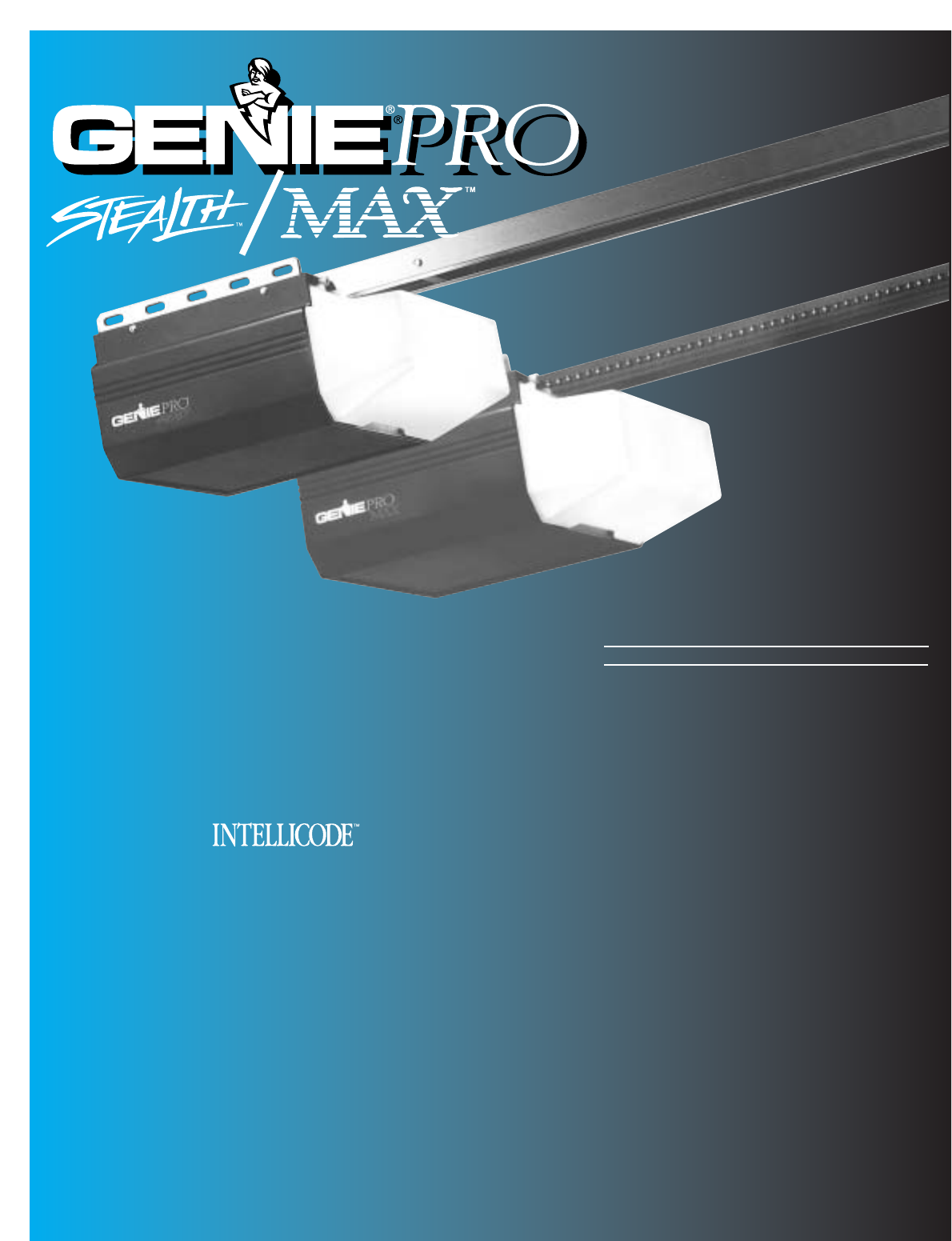
Genie Garage Door Opener Gps Ic Users Manual PrmxStl 3507535556
GPS-IC to the manual cbc61da1-faff-42db-a343-c036f99c2406
2015-01-24
: Genie Genie-Garage-Door-Opener-Gps-Ic-Users-Manual-311673 genie-garage-door-opener-gps-ic-users-manual-311673 genie pdf
Open the PDF directly: View PDF ![]() .
.
Page Count: 32
Automatic
Chain Drive/Belt Drive
Garage Door Operator
System
Owner’s Manual
SAVE FOR FUTURE REFERENCE
Customer Service
CALL: 1-800-354-3643
VISIT: WWW.GENIECOMPANY.com
3507535556
GPS-IC Series
PMX-IC B Series
AUTOMATIC GARAGE DOOR OPERATOR SYSTEMS
HANG MANUAL NEAR YOUR WALL CONTROL
Complete with Remote Control
and SERIES II Electronics
Operator MUST be installed with the included SERIES II Wall Control!
Self-diagnostic Electronic Sensory Protection System
(SAFE-T-BEAM SYSTEM) MUST Be Installed To Close Door!
TABLE OF CONTENTS
SECTION PAGE
SAFETY INFORMATION . . . . . . . . . . . . . . . . . . . . . . . . . . . . . . . . . . 2-4
PARTS IDENTIFICATION . . . . . . . . . . . . . . . . . . . . . . . . . . . . . . . . . 5-6
ASSEMBLY
1 OPERATOR ASSEMBLY . . . . . . . . . . . . . . . . . . . . . . . . . 10-11
1A Channel and Power Head Assembly . . . . . . . . . . .10
1B Rail and Power Head Assembly . . . . . . . . . . . . .10-11
INSTALLATION
2DETERMINE DOOR TYPE AND MOUNTING METHOD . . . 11
2A Installation on Track Guided Doors . . . . . . . . . 12-14
2B Installation on Trackless Doors . . . . . . . . . . . . 15-17
3 SAFE-T-BEAM®(STB) SYSTEM INSTALLATION . . . . . 18-19
Self-diagnostic “STB” System Troubleshooting . . . . 19
4WALL CONTROL INSTALLATION . . . . . . . . . . . . . . . . . . . . 20
5 CONNECT OPERATOR TO POWER . . . . . . . . . . . . . . . . . . 21
6 MAIN LIMIT SWITCH SETTINGS . . . . . . . . . . . . . . . . . . . . . 22
OPERATION
7 FORCE ADJUSTMENT . . . . . . . . . . . . . . . . . . . . . . . . . . . . . 23
Contact Reverse . . . . . . . . . . . . . . . . . . . . . . . . . . . . . . . 23
8 FINE LIMIT SWITCH ADJUSTMENTS . . . . . . . . . . . . . . . . . 24
9 REMOTE CONTROLS . . . . . . . . . . . . . . . . . . . . . . . . . . . 24-25
10 BATTERY & VISOR CLIP INSTALLATION . . . . . . . . . . . . . . 25
11 LIGHT BULB AND LENS INSTALLATION . . . . . . . . . . . . . . 26
MAINTENANCE . . . . . . . . . . . . . . . . . . . . . . . . . . . . . . . . . . . . . . . . . .27
TROUBLESHOOTING GUIDE . . . . . . . . . . . . . . . . . . . . . . . . . . . . . . 28
WIRING DIAGRAM . . . . . . . . . . . . . . . . . . . . . . . . . . . . . . . . . . . . . . . 29
ACCESSORIES . . . . . . . . . . . . . . . . . . . . . . . . . . . . . . . . . . . . . . . . . .30
WARRANTY . . . . . . . . . . . . . . . . . . . . . . . . . . . . . . . . . . . . . . . . . . . . .32

Things to consider if you are planning to “do-it-yourself.”
Whether you are replacing an existing garage door operator or installing an operator in your
garage for the first time, there are some pre-installation issues which need to be addressed.
They are as follows:
The Genie Company recommends that you read and fully understand all
information and instructions contained herein before choosing a “Do-It-Yourself ”
installation. Any questions should be directed to the Genie Company or an authorized
Genie Dealer.
6To avoid damage to your door and/or
operator, make sure you disable any door
locks prior to installing your operator.
2
PRE-INSTALLATION CHECK LIST FOR HELP-1.800.354.3643 OR GENIECOMPANY.COM
1Check your ceiling where the power
head of your new unit will be mounted.
Plan how you will be mounting the power head.
It is possible that ceiling joists may not be in the
exact position needed with respect to the garage
door operator. In any case, it may be necessary
to add an additional bracket and
fasteners (not
included with your new door operator kit).
2Check the wall directly above the garage
door.The door operator’s header bracket
must be securely fastened to this wall. Insure
that the structure will provide a strong mounting
location.
3Check to see if the mounting location
for the Safe-T-Beam®System (STB)is
clear from obstruction and has a wood
surface available for attaching the STB
brackets.The brackets may also be attached to
concrete if necessary but extra tools and special
fasteners (not supplied) will be required.
NOTE: 1-1/2" “STB”bracket adapters
are available through your local Genie Dealer.
4Is your garage door made of
light-weight steel, aluminum, fiberglass
or glass panels?Additional support bracing
must be added to these type doors. If this is the
case, please contact the door distributor or
manufacturer so that they can furnish you with a
“bracing kit.”
7Insure that your door is properly balanced
and moving freely. SEE WARNING BELOW.
If your door sticks, binds, or is out of
balance, have it adjusted by a professional.
Door springs, cables, pulleys, brackets and
associated hardware are under extreme
tension and can cause serious injury or
death.
WARNING
(The issue numbers below refer to the circled numbers in the illustrations on page 3.)
8(NOT SHOWN) If your garage does not have
a separate entry door, you might want to
consider an emergency release kit (GER-2)for
installation on your garage door. See page 30.
DO NOT USE EXTENSION CORD!
Extension cords can cause dangerous
overheating conditions.
DO NOT USE PORTABLE GENERATOR!
This product is designed to operate on
standard house current. Do not use
alternate power supplies.
WARNING
5You need a 110-120 Volt power supply
available.If you plan to plug the unit into a
standard electrical outlet, is one available? The
outlet should be no more than about 3 feet from the
power head once it is mounted. (The cord is 4 ft. in
length.) SEE WARNING BELOW.
3
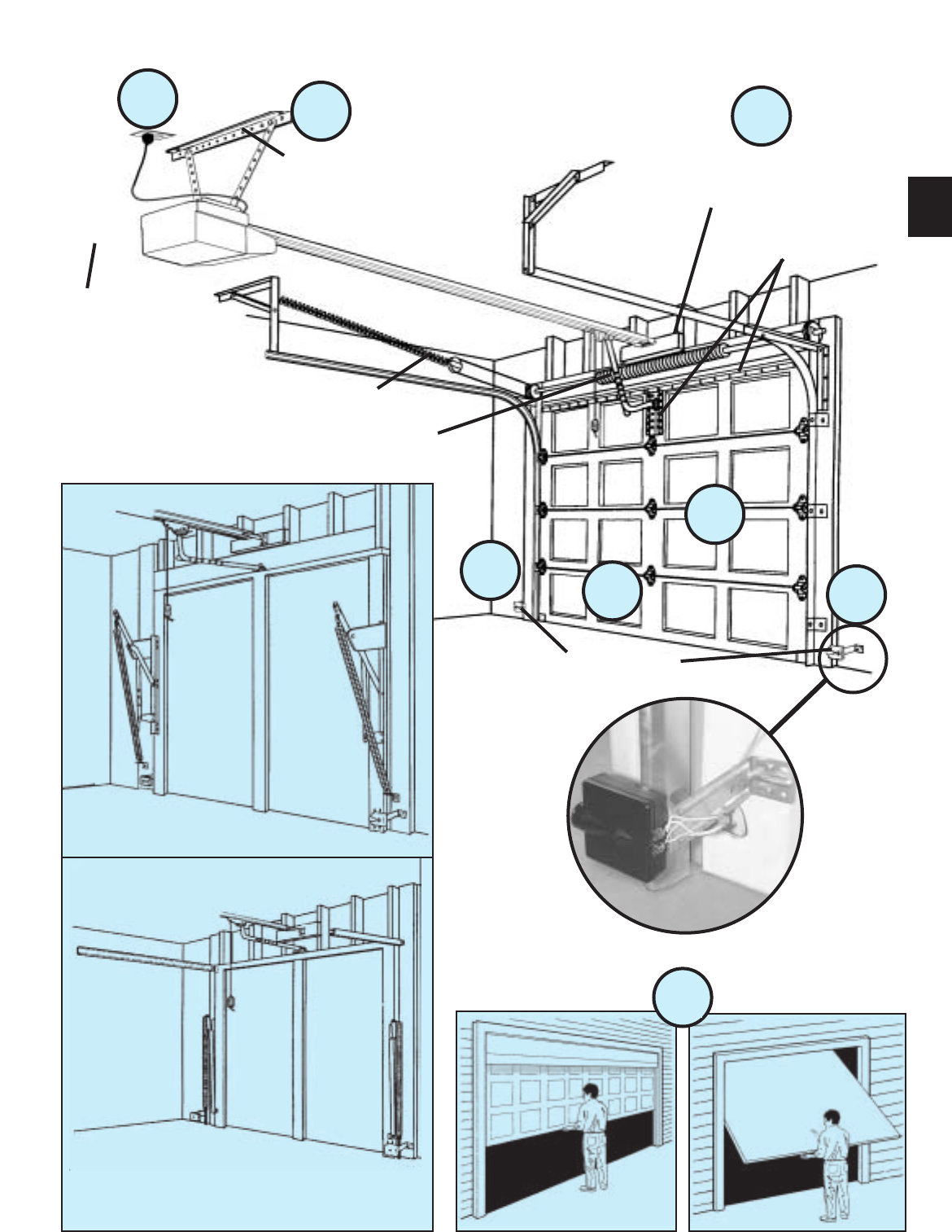
TYPICAL SECTIONAL DOOR INSTALLATION
5
TYPICAL
SUPPORT
BRACKET
EXTENSION SPRING
OR
TORSION SPRING
SAFE-T-BEAM®
BRACES
ADDED
HEADER BRACKET
MOUNTING BOARD
36”POWER CORD
TO
120V GROUNDED
OUTLET
6
4
3
12
3
TYPICAL (TRACK GUIDED)
1-PIECE DOOR INSTALLATION
7
SECTIONAL DOOR ONE-PIECE DOOR
TYPICAL (TRACKLESS)
1-PIECE DOOR INSTALLATION
4WARNING:
Garage doors are large, heavy objects that move with the help of springs
under high tension and electric motors. Since moving objects, springs under
tension, and electric motors can cause injuries, your safety and the safety of
others depend on you reading the information in this manual. If you have
questions or do not understand the information presented, call your nearest
service representative
In this section and those that follow, the words Danger, Warning, and
Caution are used to emphasize important safety information.
The word:
DANGER means that severe injury or death will result from failure
to follow instructions.
WARNING means that severe injury or death can result from failure
to follow instructions.
CAUTION means that property damage or injury can result from failure
to follow instruction.
The word NOTE is used to indicate important steps to be followed
or important considerations.
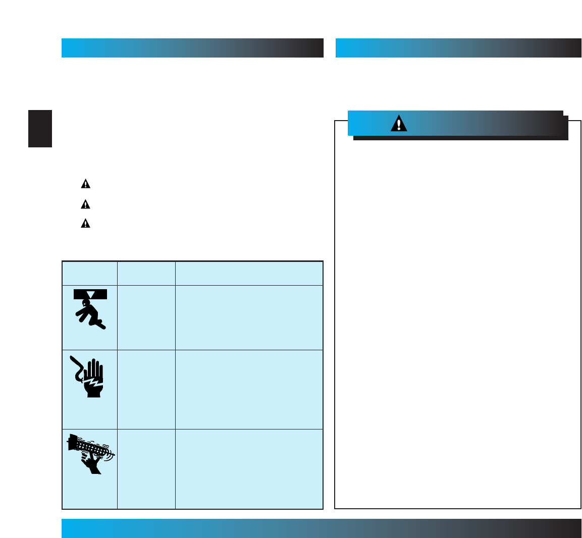
OVERVIEW OF
POTENTIAL HAZARDS
POTENTIAL
HAZARD
EFFECT PREVENTION
Keep people clear of opening while door is
moving.
Do Not allow children to play with the door
operator.
Do Not operate a door that jams or one that
has a broken spring.
MOVING
DOOR
WARNING:
Can Cause
Serious Injury
or Death
Turn off power before removing operator cover.
When replacing cover, make sure wires are not
pinched or near moving parts.
Operator must be properly grounded.
ELECTRICAL
SHOCK
WARNING:
Can Cause
Serious Injury
or Death
Do Not try to remove, repair or adjust springs
or anything to which door spring parts are
fastened, such as, wood blocks, steel
brackets, cables or other like items.
Repairs and adjustments must be made by a
trained service person using proper tools and
instructions.
HIGH
SPRING
TENSION
WARNING:
Can Cause
Serious Injury
or Death
Safe-T-Beam
®
(STB) Non-Contact Reversing System
Places an invisible beam across door opening that reverses the door during down travel to the fully open
position if anything passes through beam.
Safe-T-Reverse
®
Contact Reversing System
Automatically stops and reverses a closing door within 2 seconds of contact with an object.
Safe-T-Stop
®
Timed Reversed System
Automatically opens a closing door, if door does not close within 30 seconds.
Force Guard
®
Control
Used to set the force required for opening and closing door. For maximum safety, set the minimum force
required to fully open and close door.
Automatic Lighting System
One or two light bulbs (depending on model) up to 100 Watts max. each are used for safer entries and exits.
The light turns on when door is activated and automatically turns off 4.5 minutes later.
Manual Emergency Release
Allows the garage door to be opened or closed manually for emergencies or maintenance.
IMPORTANT
INSTALLATION
INSTRUCTIONS
1. READ AND FOLLOW ALL SAFETY, INSTALLATION AND
OPERATION INSTRUCTIONS. If you have any questions or
do not understand an instruction, call your service
representative.
2. Do Not install operator on an improperly balanced door. An
improperly balanced door could cause severe injury. Repairs
and adjustments to cables, spring assembly, and other
hardware must be made by a trained service person using
proper tools and instructions.
3. Remove all ropes and disable all locks connected to the door
before installing operator.
4. Install door operator 7 feet or more above the floor. Mount the
emergency release knob 6 feet above the floor.
5. Do Not connect the operator to the source of power until
instructed to do so.
6. Locate the control button:
•Within sight of door.
• At a minimum height of 5 feet, so small children cannot
reach it.
• Away from all moving parts of the door.
7. Install the entrapment WARNING label next to the wall button or
console. Install the emergency release tag on, or next to, the
emergency release
8. The operator must reverse when the door contacts a 1-1/2 inch
high object on the floor at the center of the doorway. This is about
the size of a 2”x 4”board laid flat.
To reduce the risk of
severe injury or death:
WARNING:
SAFETY INFORMATION OPERATOR INSTALLATION
SAFETY FEATURES (varies by model)
NOTE: Accessories vary by model.
FASTENERS - Shown full size. See Parts List for description.
105
10 4 103
101
106
126
124
12 5
Lag Screw, 1/4”x 2”
Cotter Pin
Clevis Pin
Bolt, 3/8”-16 x 7/8”
Phillips Hex Head Screw, No. 10 x 1-1/4”
Insulated Staple
Bolt, 5/16”-18 x 1/2”
100
69
112
79
81
82
127
N/A
N/A
96
91
92
90
89
Pan Head Screw #6 x 1-1/4”
128
N/A
10
PARTS IDENTIFICATION FOR HELP-1.800.354.3643 OR GENIECOMPANY.COM
9
N/A
Hex Head Screw
No. 8 x 3/4”
Cold Head Pin
Pan Head
Phillips Screw
No. 8 x 5/8”
Speed Nut
OR
N/A
N/A
Nut, 3/8-16
1/4”-20 x 3/4”
Self-Drilling Screw
Bolt, #10-24 x 1/2”
5
Wall Control Screw
N/A
remotes
vary by model
N/A
Stealth Power Head
2
3
4
567
8
9
10
1
12
13
14
15
16
17
18
19
20
11
22
23
24
25
26
27
28
29
30
21
32
33
34
35
36
37
38
39
31
40
12
12
12
12
11
19
3
12
26
26
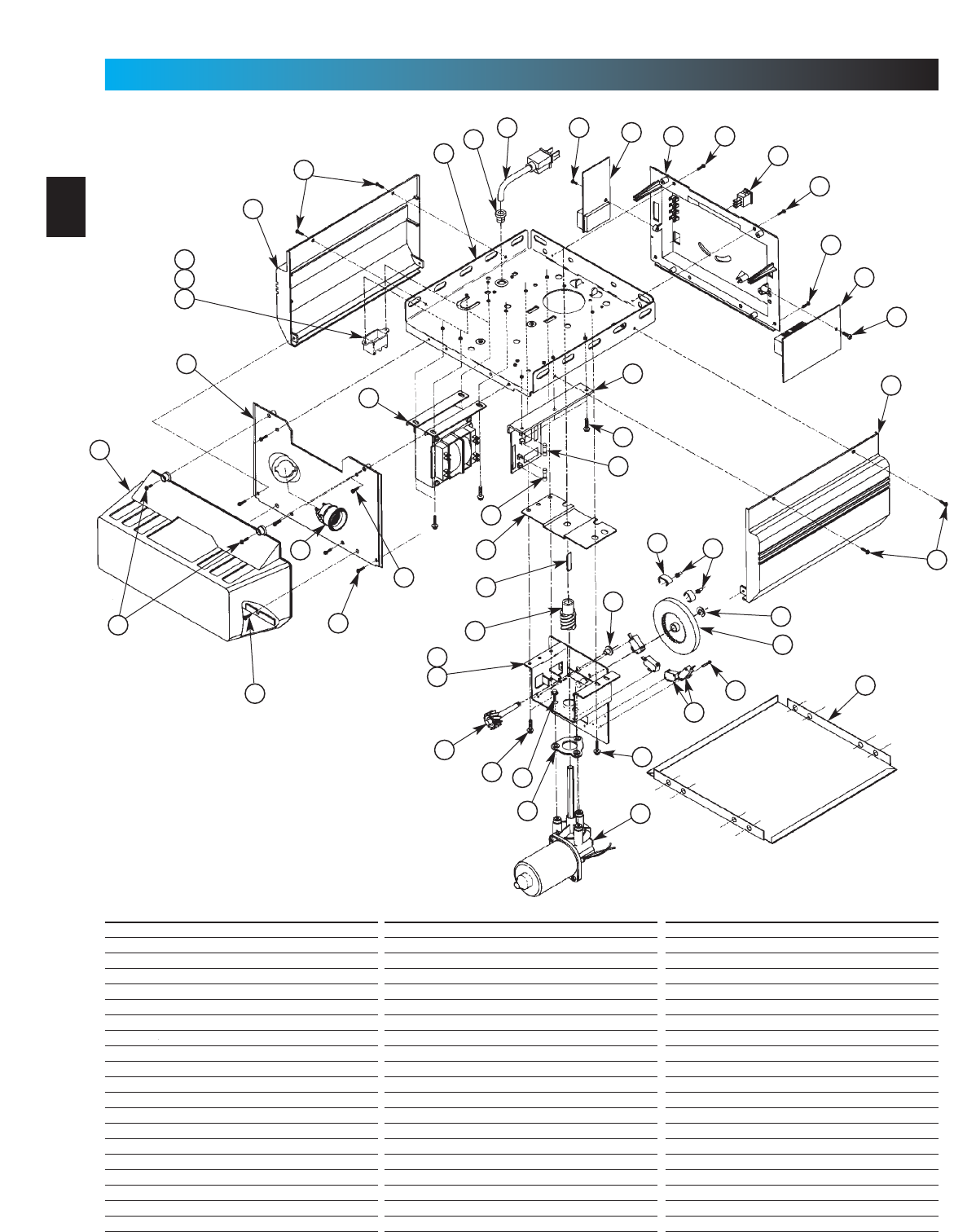
Item Part Name
1Lens
2Front Cover
3Side Cover (by series/model)
4Top Plate Assembly
5Strain Relief
6Cord & Plug Assembly
7Component Panel (by series/model)
8Bottom Cover
9Screw, #8 x .75 Phil Hx Hd/W Sf Tap
10 Screw, #8 x .62 Phil Pan Hd/W Sf Tap
11 Screw, #8 x .50 Slt Hx Hd/W Sf Tap
12 Screw, #8 x .38 Slt Hx Hd/W Sf Tap
13 Light Socket (by series/model)
14 Terminal Block & Lug
15 M.O.V. Assembly
16 Receiver Assembly
17 Limit Set Switch
18 Sequencer Assembly
19 Screw, #6 x .38 Slt Hx Hd/W Sf Tap
20 Transformer Assembly (by series/model)
6
PARTS IDENTIFICATION FOR HELP-1.800.354.3643 OR GENIECOMPANY.COM
Item Part Name
21 Rectifier Board Assembly
22 Fuse (F1), UL
23 Fuse (F2), UL
24 Limit Gear Shroud
25 Motor Bracket
26 Screw, #10 x 3/8”HH
27 Limit Plate/Pin Assembly
28 Limit Switch
29 Screw, #4-40 x 5/8”Slot HH w/Wshr, Sf Tap
30 Motor Assembly
31 Motor Adapter Plate
32 Screw, 1/4"-20 x 1/2”Slt HH w/Wshr
33 Limit Worm Gear
34 Limit Gear Bushing
35 Limit Worm Drive
36 Limit Worm Shim
37 Limit Wheel
38 Retaining Ring
39 Limit Cam
40 Limit Pinion, 8 tooth
Item Part Name
41 Capacitor
42 Capacitor Clamp
43 Screw, #10-24 x 1/2”, Slot HH Sf-Tap
44 Nut, #10-32, Hex Serrated Flange
45 Circuit Board
46 C.B. Bracket
47 Circuit Board Mount
48 Screw, #10-16 x 5/8”, HH Sf Tap
49 Top Gear Housing
50 Middle Gear Housing
51 Bottom Gear Housing
52 Drive Shaft Bushing
53 Drive Thrust Washer
54 Drive Shaft
55 1/2”Retaining Ring
56 Main Drive Worm Gear
57 Optical Interrupt Wheel
58 Motor Flanged Bushing
59 Motor Thrust Washer
60 Poly Thrust Washer
Combined Parts List
7
PARTS IDENTIFICATION FOR HELP-1.800.354.3643 OR GENIECOMPANY.COM
Item Part Name
61 Main Drive Worm
62 Screw, #8 x 3-1/8”Slot HH, Sf Tap
63 Limit Switch Plate
64 Screw, #6 x 3/8”Phillips w/Wshr, Sf Tap
65 Screw, #4 x 5/8”, Slot HH w/Wshr, Sf Tap
2
10
12
46
12
12
3
12
45
47
5
6
712
48
12
11
12
40
39
37
4
52 64
3
12
65
28
63
41
42
25
43
13
11
49
53
33
35
50
54
57
58
59
60
59
61
59
58
30
44
8
62
51
52
53
56
55
1
9
PRO-MAX Power Head
Channel
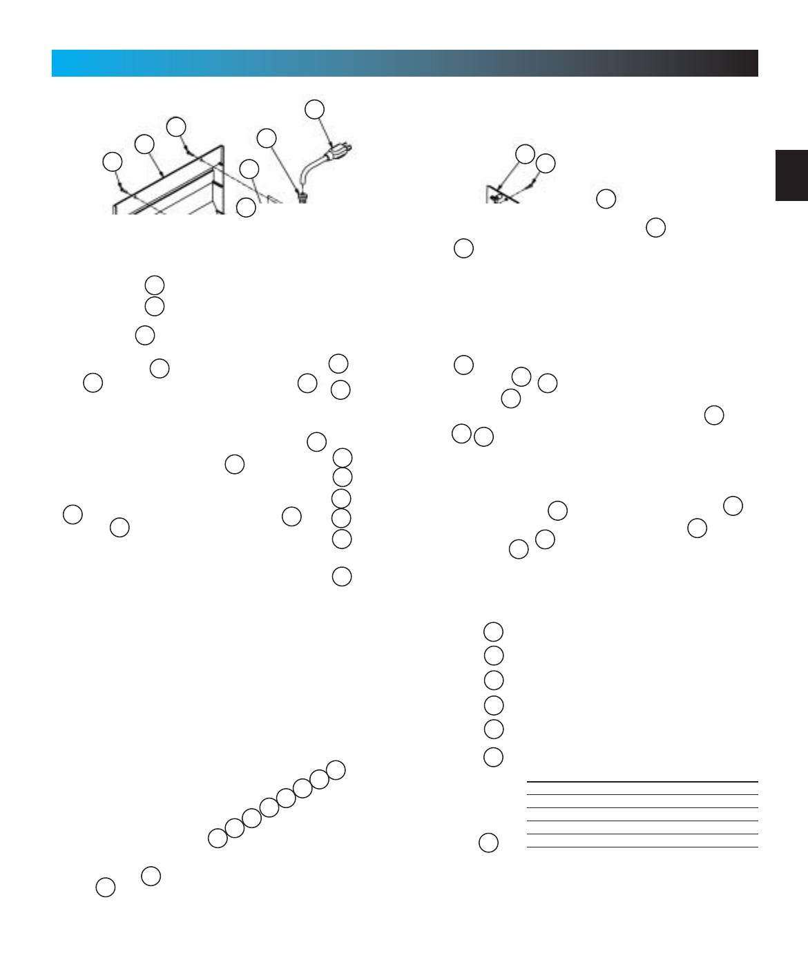
Item Part Name
66 Belt & Bullet Assembly - 7’6”Door
(Belt Models Only)
Belt & Bullet Assembly - 8’Door
(Belt Models Only)
Belt & Bullet Assembly - 10’Door
(Belt Models Only)
Belt & Bullet Assembly - 12’Door
(Belt Models Only)
67 Sprocket Bushing
68 Sprocket, 10 Tooth - 7’6”& 8’Doors
(Chain Models Only)
Sprocket, 12 Tooth - 10’Door
(Chain Models Only)
Drive Sprocket, 18 Tooth - 7’6”& 8’Doors
(Belt Models Only)
Drive Sprocket - 10’Door
(Belt Models Only)
69 Screw, #10-24 x .50 Hx Hd
70 Sprocket Bracket (Chain Models Only)
Sprocket Bracket - 7’6”& 8’Doors
(Belt Models Only)
Sprocket Bracket - 10’Door (Belt Only)
Sprocket Bracket - 12’Door (Belt Only)
71 Screw, #10-24 x .38 Hx Hd/W
8
PARTS IDENTIFICATION FOR HELP-1.800.354.3643 OR GENIECOMPANY.COM
Item Part Name
72 Channel - 7’6”Door (128”LG)
Channel - 8’Door (146”LG)
Channel - 10’Door (170.75”LG)
Channel - 12’Door (188”LG)
73 Pulley (Chain Models Only)
Pulley (Belt Models Only)
74 Carriage Bolt, 5/16”-18 x 4.0
75 Carriage Pin, 5/16”x 1.25
76 Pulley Bracket Assembly
77 End Bracket
78 Hex Flange Nut, 5/16”-18 (Chain Only)
Flat Washer (Belt Models Only)
(2)Hex Jam Nut, 5/16-18 (Belt Models Only)
79 Lag Screw, 1/4”x 2”Hx Hd/W
80 Header Bracket
81 Speed Nut
82 Cold Header Pin
83 Carriage Stop
84
Roller Chain -7’6”Door (Chain Only)(242.5”)
Roller Chain - 8’Door (Chain Only)(278.5”)
Roller Chain -10’Door (Chain Only)(328.5”)
8mm Belt
Item Part Name
85 Chain Bullet
Belt Bullet
Belt Retainer
Screw, #6-32 x 1/2”Phil Pan Hd Slf Tap
86 Carriage Slide
87
Emerg. Release Cord -7’6”Doors(26.5”)
Emergency Release Cord -8’ & 10’Doors (56.5”)
Emergency Release Cord -12’Doors(96.0”)
88 Emergency Release Knob (Red)
89 Cotter Pin
90 Clevis Pin
91 Screw, 3/8”-16 x .87 Hx Hd Mch
92 Hex Nut, 3/8”-16
93 Curved Door Arm
94 Straight Door Arm
95 Door Bracket
96 Screw, 1/4”-20 x 3/4”Hx Hd, Sf Tap
97 Carriage Assembly
98 Carriage Cap
99 Screw, #10-14 x 1-5/16”Hx Hd
100 Wall Console (Series II )
101 Wall Button (Series II ) (lit primary)
Wall Button (unlit secondary)
Combined Parts List
81
69
71
71
71
73
74
75
76
77
78 79 80
83
71
92
93
90
96 89
95
82
66 85
98
86
97
87
88 90
89 99
71
94
91
70
71
83
84
69 67
68
67
79
72
9
Rail
PARTS IDENTIFICATION FOR HELP-1.800.354.3643 OR GENIECOMPANY.COM
Item Part Name
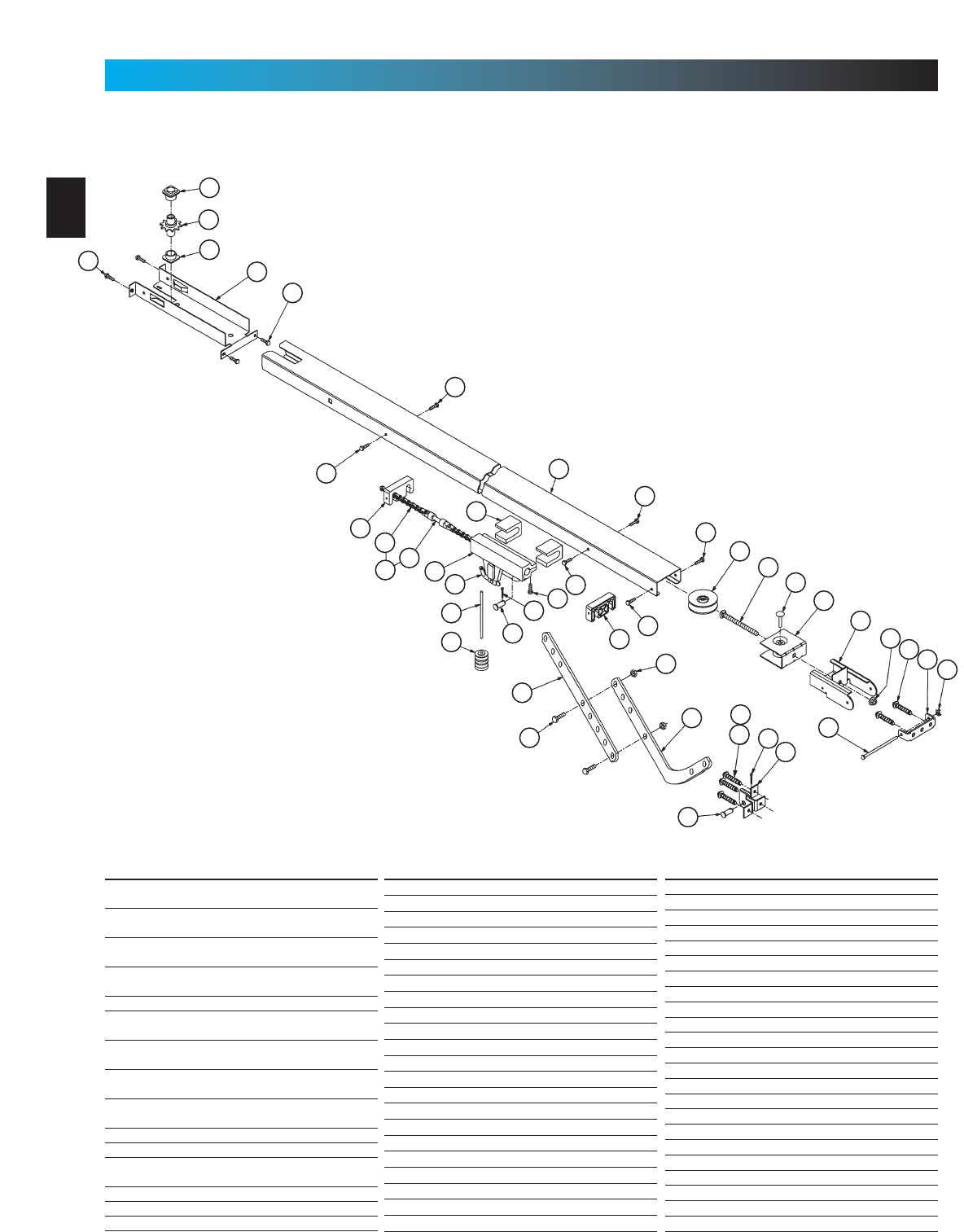
102 Boom Support Kit (not shown)
103 Safety & Maintenance Guide
104 Emergency Release Tag (Tri-L)
105 Entrapment WARNING Label
106 Wire
110 Rail (L=112.475”)
111 Screw, 5/16”-18 x 3/4”
112 Screw, 5/16”x 1/2”HH w/Wshr
113Pulley Support
114 Chain
115 Sprocket Saddle
116 Screw, 5/16”-18 x 2-1/4”HH
117 Bolt Retainer
118 Screw, 5/16”-18 x 1-1/8”HH
119 Large Pulley Bushing
120 Square Nut, 5/16”-18
121 Screw, 1/4”-20 1”HH
122 Hex Nut/Lockwasher, 1/4”-20
123 5/16-18 Lock Nut
124 STB System Sensor (Green LED)
68
88
90
95
96
89
93
91
92
115
94
114
86
110
122
121
112
69
73
76
117
120
113
123
90
89
97
87
82
80
79
116
81
119
118
111
Item Part Name
125 STB System Source (Red LED)
126 STB Mounting Brackets (2)
127 Screw, 1-1/4”Phillips HH
128 Insulated Staples
79
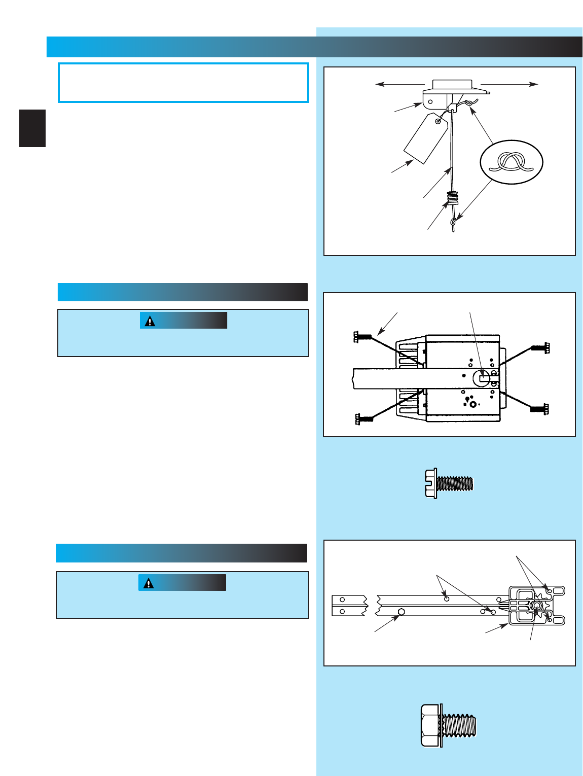
Fig. 1-3
No. 10-24 x 1/2”Hex Head Screws
5/16”x 1/2”Hex Head Screws
“D”-Shaft and Hole
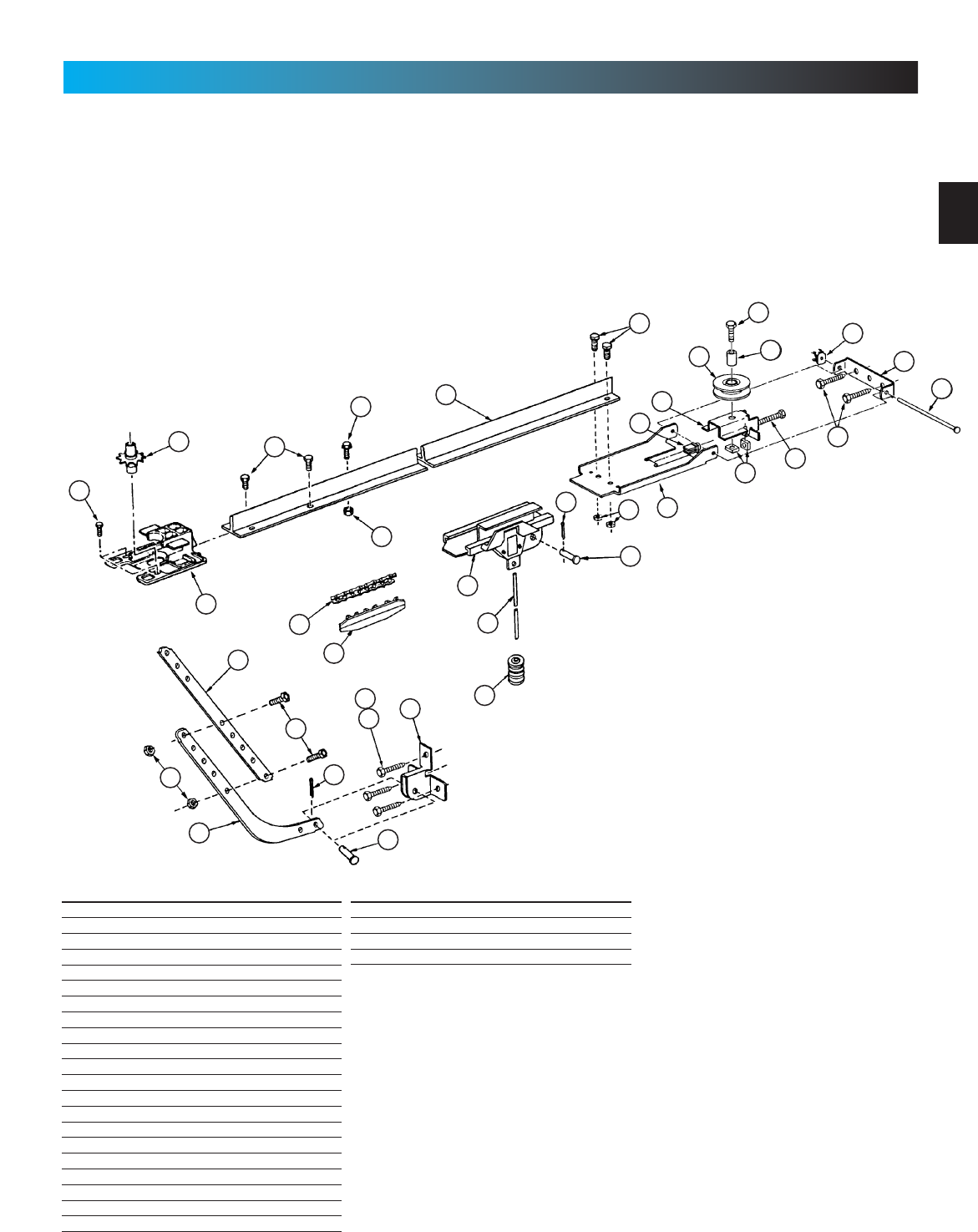
3. Place power head and channel on clean, flat surface.
4. Slide drive end of channel down over “D”-shaft on top of
power head (Fig. 1-2).
•Support header end of channel level with power head.
•Slide carriage to align “D”-shaft with “D”-hole in sprocket.
•Slide channel down “D”-shaft flush with power head.
5. Fasten channel to power head .
•Align mounting holes in front and rear of power head frame.
•Insert and securely tighten the four (4) No. 10 x 1/2”hex
head screws [69].
NOTE: Chain inner-slide or belt bullet should remain at
mid-travel when assembling to power head to provide proper
travel when setting limits.
1. Attach emergency release knob cord (Fig. 1-1).
•Tie overhand knot in end of cord.
•Thread cord through knob so knot is inside knob.
•Thread cord through hole in carriage lever.
•Tie overhand knot in other end of cord.
Do Not cut cord until after power head is mounted.
2. Attach emergency release tag (Fig. 1-1).
•Thread wire through hole in carriage lever.
•Wrap wire around itself, tie securely.
PLEASE NOTE THE ASSEMBLY PROCEDURES
ARE DIFFERENT FOR RAIL AND CHANNEL. BE
SURE TO FOLLOW THE APPLICABLE STEPS.
Fig. 1-2
Fig. 1-1
Do Not attempt to run power head or to set limits until
operator is fully assembled and attached to the door.
“D”-Shaft and Hole
Hex Head Screws
Carriage Stop
CAUTION
Do Not attempt to run power head or to set limits until
operator is fully assembled and attached to the door.
Toward Door Toward Power Head
Carriage
No. 10 x 1/2”Hex Head Screw
5/16”x 1/2”Hex Head Washer Screw
Emergency
Release
Tag
Emergency
Release
Cord
Emergency
Release
Knob
Sprocket Saddle
1...
OPERATOR ASSEMBLY
FOR HELP-1.800.354.3643 OR GENIECOMPANY.COM
10
CHANNEL & POWER HEAD ASSEMBLY
RAIL & POWER HEAD ASSEMBLY
3. Place power head and rail on clean, flat surface.
4. Slide drive end of rail down over “D”-shaft on top
of power head (Fig. 1-3).
•Support header end of rail level with power head.
•Slide carriage enough to align “D”-shaft with “D”-hole
in sprocket.
•Slide rail down “D”-shaft flush with power head.
drags on the rail
CAUTION
OPEN BLUE PARTS BAG
Screws for attaching light cover are included in this
bag. Please set aside for use later.
[69]
[112]
[69]
[69]
[112]
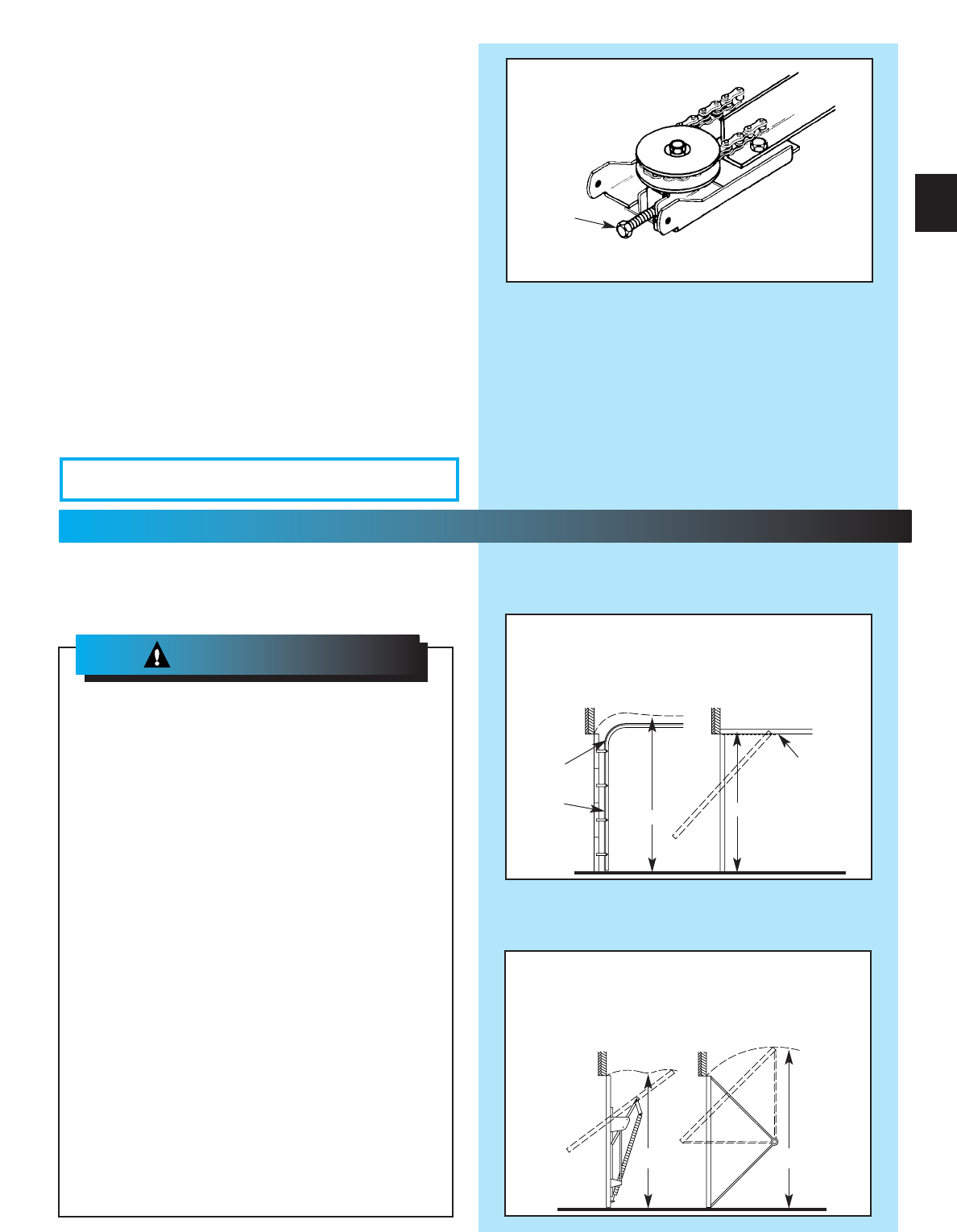
Fig. 1-4
Adjusting
Bolt
WHAT TYPE OF DOOR DO YOU HAVE?
Look at the drawings below. They tell you where
to find the installation instructions you need
Track Guided Doors
SEE SECTION 2A
Trackless Doors
SEE SECTION 2B.
Section Door With
Curved Track Hardware
1-Piece Door With
Horizontal Track Hardware
Curved
Track
with
Vertical
Section
Straight Track
(Horizontal Only)
1-Piece Door
Jamb Type Hardware
(No Track)
1-Piece Door
Pivot Type Hardware
(No Track)
5. Fasten rail to power head.
•Align mounting holes of sprocket saddle, rail
and power head frame.
•Insert the two (2) 5/16”x 1/2”hex head
screws[112], then two (2) No. 10-24 x 1/2”hex
head screws [69].
•Tighten screws.
NOTE: Inner-slide/bullet should remain at mid-travel
when assembling to power head to provide proper
travel when setting limits.
6. Use adjusting bolt to set chain tension (Fig. 1-4)
•Chain should sag slightly but not so much that it
drags on the rail.
“H”“H”
“H”
DOTTED LINE AT “H”
INDICATES HIGHEST
POINT OF TRAVEL
“H”
2...
INSTALLATION
FOR HELP-1.800.354.3643 OR GENIECOMPANY.COM
11
WARNING:
IMPORTANT
INSTALLATION
INSTRUCTIONS
1. READ AND FOLLOW ALL SAFETY, INSTALLATION AND
OPERATION INSTRUCTIONS. If you have any questions or
do not understand an instruction, call your service
representative.
2. Do Not install operator on an improperly balanced door. An
improperly balanced door could cause severe injury. Repairs
and adjustments to cables, spring assembly, and other
hardware must be made by a trained service person using
proper tools and instructions.
3. Remove all ropes and disable all locks connected to the door
before installing operator.
4. Install door operator 7 feet or more above the floor. Mount the
emergency release knob 6 feet above the floor.
5. Do Not connect the operator to the source of power until
instructed to do so.
6. Locate the control button:
•Within sight of door.
• At a minimum height of 5 feet, so small children cannot
reach it.
• Away from all moving parts of the door.
7. Install the entrapment WARNING label next to the wall button or
console. Install the emergency release tag on, or next to, the
emergency release.
8. The operator must reverse when the door contacts a 1-1/2 inch
high object on the floor at the center of the doorway. This is about
the size of a 2”x 4”board laid flat.
To reduce the risk of
severe injury or death:
WARNING:
OPEN ORANGE PARTS BAG
WARNING
•Do Not try to remove, repair or adjust
springs or anything to which door spring
parts are fastened, such as, wood blocks,
steel brackets, cables or other like items.
Repairs and adjustments must be made by
a trained service person using proper tools
and instructions.
•Handles and other door projections can
catch clothing. Remove ropes, hooks,
hangers, decorative or security items
mounted to door.
•Be sure Emergency Release Cord does not
catch on roof carrier or other vehicle parts.
1.
Establish center line of door and header (Fig. 2-1).
•Close door.
•Measure door width. Mark center.
•Use straight edge to draw vertical line “V.”
–down door about 6”.
–on top of door.
–up header about 20”.
2. Establish Header Bracket position (Fig. 2-2).
•Watch top edge of door as you raise it.
•Stop door when top edge reaches highest point
of travel.
•Measure distance from top edge of door to floor.
•Add 2-1/2”to this measurement.
•Close door.
•Mark header at this height.
•If door spring is in the way, mark header 2-1/2”
above the spring.
•Draw horizontal line “H”across line “V”at this
point (Fig 2-1).
NOTE: Header bracket must be at least 2-1/2”above
high point of door travel. It can be installed higher if
door spring is in the way. Do Not move the spring.
Fig. 2-2
Door
Header
Line “H”
Line “H”Can Be
Drawn Above
Spring
Fig. 2-1
Line “V”
(Vertical Center Line
of Door)
Inside of Door
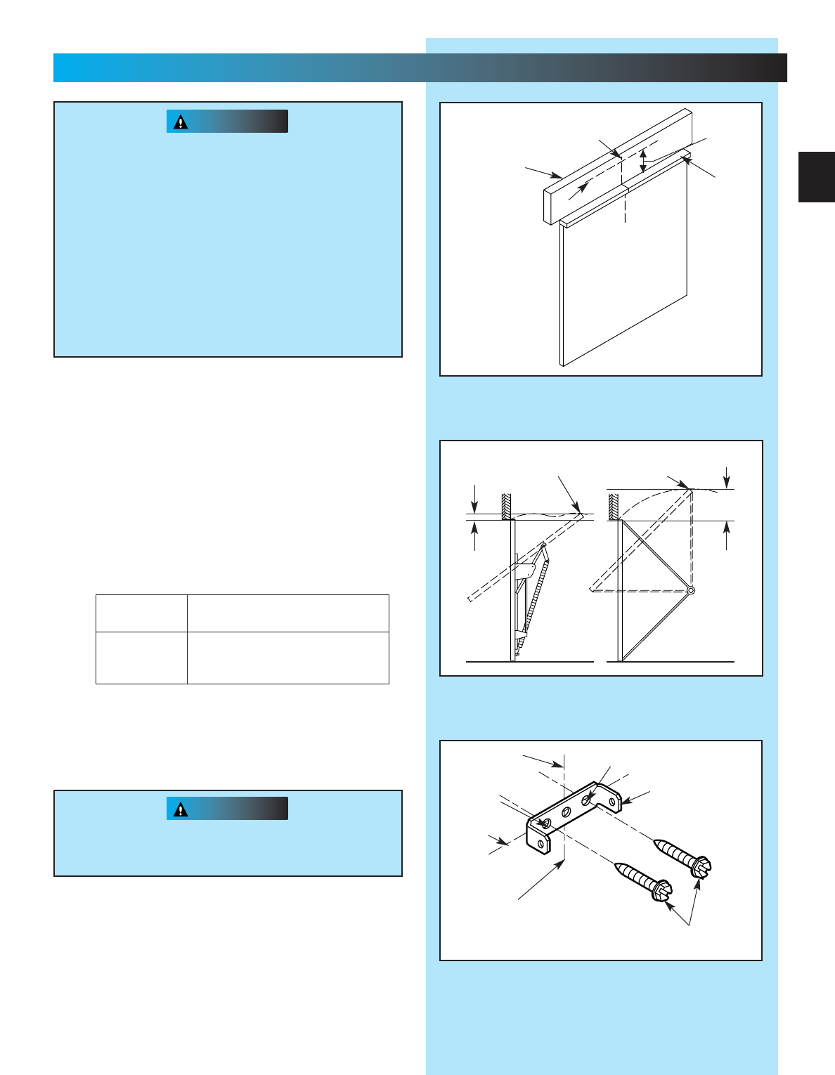
Alternate Mounting Methods
NOTE: Materials for mounting are not included
Angle Iron Method Conduit Method
CAUTION
CAUTION
Fig. 2-5
Mounting bracket must be fastened to garage
framing. Do Not fasten to drywall, particle board,
plaster or other such materials.
Power Head
Channel/Rail
Assembly
6. Mount power head
(See Section 2 MOUNTING METHODS).
•Be sure channel/rail assembly and power head
are on door center line (Line “V”).
•Check the illustrations. Decide which mounting
method you will use. Materials for mounting are
not included.
•After power head is installed, remove
supporting material.
•Close door.
7. Install door braces (See CAUTION below).
Fig. 2-4
Header
Bracket
Spring
Header
Door
Support if
necessary to
clear spring
Center Line
Doors made of masonite, lightweight wood, fiber-
glass, and metal must be properly braced before
mounting Door Operator.
Contact door manufacturer or distributor for bracing
instructions.
Header bracket must be fastened to garage
framing. Do Not fasten to drywall, particle
board, plaster or other such materials.
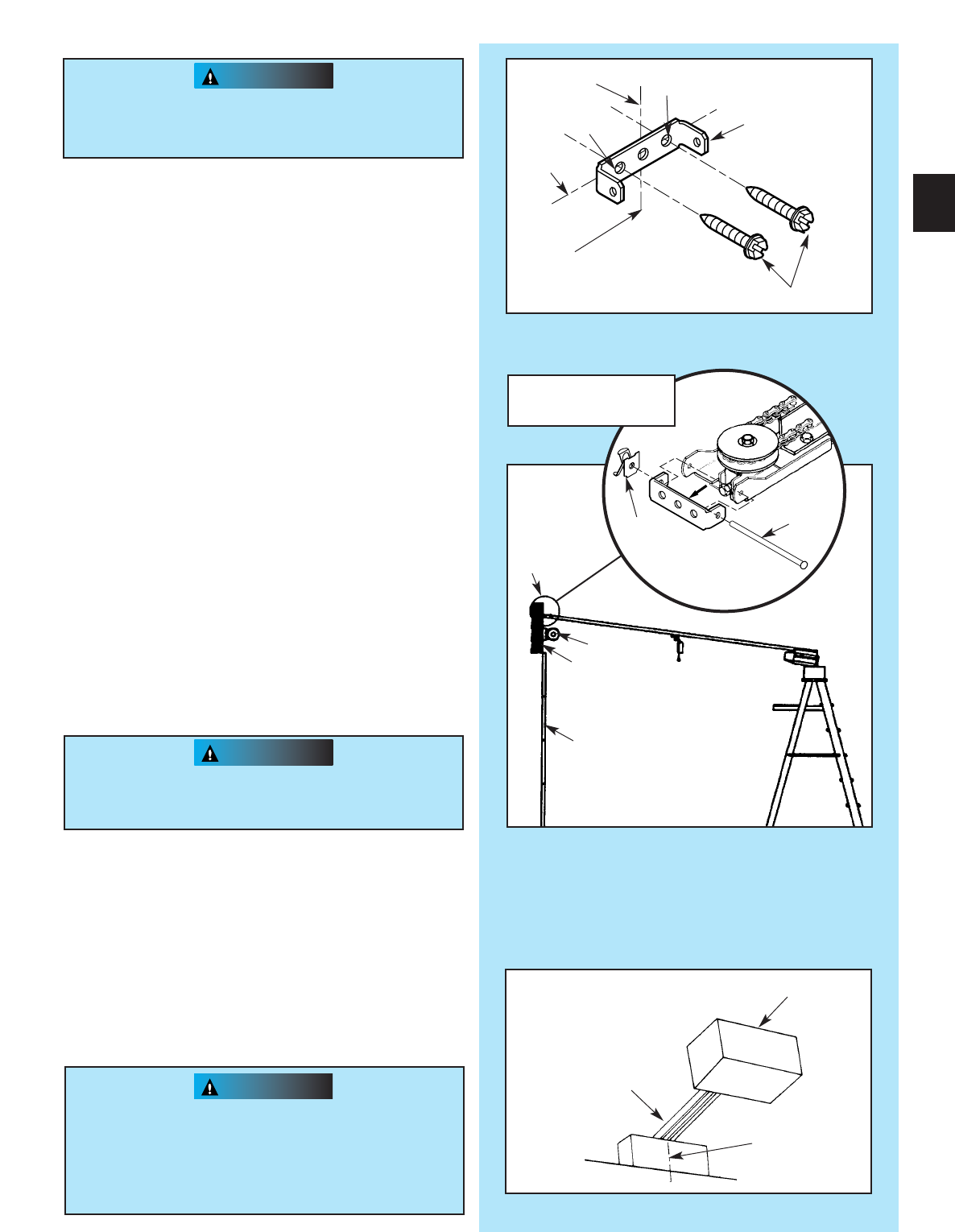
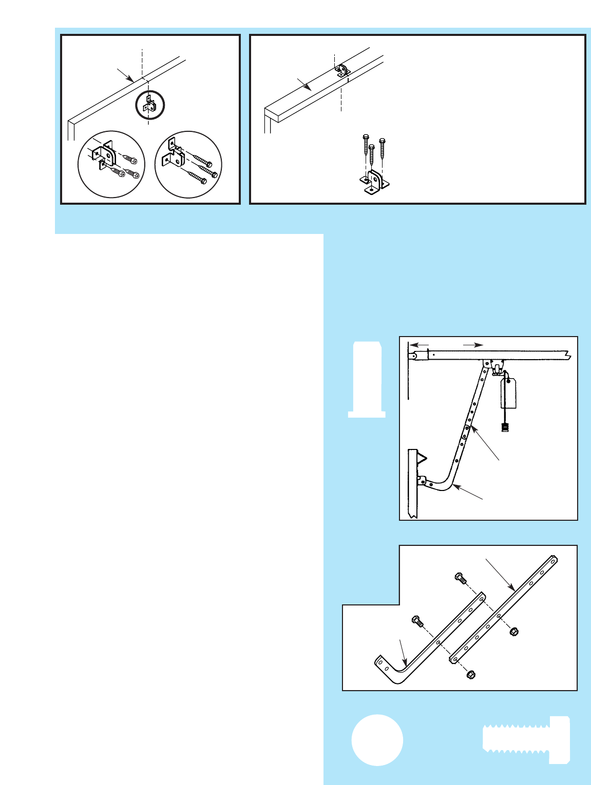
3. Install header bracket (Fig. 2-3)
•Place bracket so:
–center hole is on line “V.”
–all holes are on line “H.”
•Mark hole positions “A”and “B.”
•Drill 5/32”holes at marked positions.
•Fasten bracket to header using two (2) 1/4”x 2”
lag screws [79].
4. Attach channel/rail assembly to header
bracket (Fig. 2-4).
•Fasten header end of the channel/rail to the
Header bracket with cold header pin [82].
•Install speed nut [81].
•Support power head above floor, use:
–rope.
–ladder with cardboard packing.
–wood.
5. Level rail assembly and power head (Fig. 2-5).
•Raise and support power head above door tracks.
•Open door.
•Level channel/rail assembly and
support temporarily.
•Center channel/rail assembly and power head
on line “V”of door.
NOTE: The channel/rail assembly and power head
should be level if possible. If necessary, power
head may be mounted lower. However mounted,
moving door must not touch channel/rail assembly.
Fig. 2-3
Line “V”
Line “H”
“A”
“B”
Header Bracket
Lag Screws
Vertical
Centerline
of Door
13
CAUTION
T-rail shown. Channel
attachment is same.
[79]
[81]
[82]
Speed nut
Cold header
pin
8. Install door bracket (Fig. 2-6).
•Contact door manufacturer.
NOTE: Self-drilling screws are intended for use with
light-weight door only, while lag screws are meant
for wood doors only.
Because door designs vary, modifications may
be required and additional materials needed. Please
contact your door manufacturer with any questions
concerning your door.
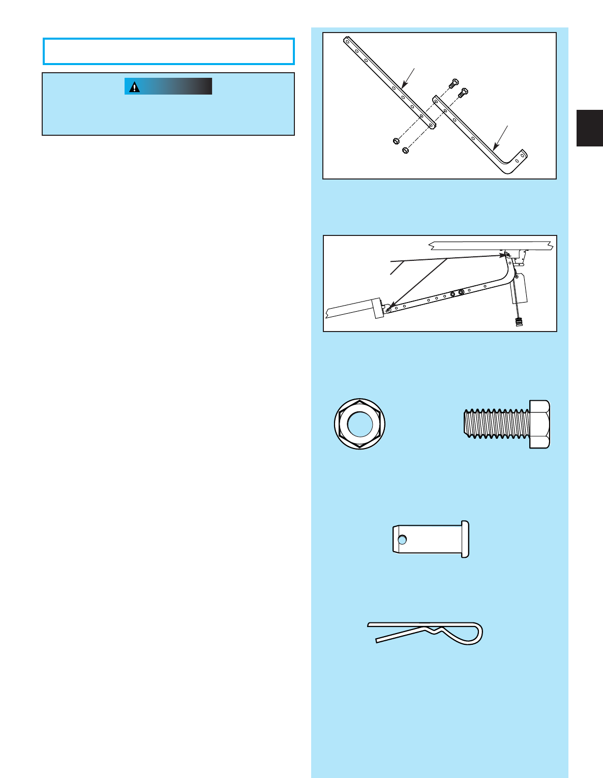
9. Install door arms (Fig. 2-7).
•Attach straight door arm to carriage.
–slip straight door arm into slot at bottom of
carriage as shown.
–secure with clevis pin [90] and cotter pin [89] .
•Attach short end of curved door arm to door
bracket as shown.
–slip short end of curved door arm into slot in
door bracket.
–secure with clevis pin and cotter pin.
•Release carriage (See emergency release tag).
–slide carriage towards closed door.
–stop carriage 14”minimum from door.
10. Join door arm sections (Fig. 2-8).
•Use two (2) 3/8”x 7/8”hex bolts [91], and hex
flange nuts [92].
–use any two holes as far apart as possible.
–slide carriage back and forth as needed to
align holes.
•Tighten hex nuts securely.
11 . Adjust emergency release cord length.
•Mount the emergency release knob 6 feet from
the floor.
•Retie overhand knot and trim excess cord.
DO NOT plug power cord into outlet.
Go to Section 3-SAFE-T-BEAM®
SYSTEM INSTALLATION.
– PROCEED TO PAGE 18 –
Fig. 2-8
Straight door arm
Curved door arm
Fig. 2-6
Fig. 2-7
14”MIN.
Straight door arm
Curved door arm
Top of Door
Dessus de la porte
Top of Door
Dessus de la porte
“V”“V”
“V”
CAUTION
WARNING
Header bracket must be fastened to garage
framing. Do Not fasten to drywall, particle
board, plaster or other such materials.
1.
Establish center line of door and header (Fig. 2-9).
•Close door.
•Measure door width. Mark center.
•Use straight edge to draw vertical line “V.”
–down door about 6.”
–on top of door.
–up header about 20”.
2. Determine door rise (Fig. 2-10).
•Open door to highest point of travel.
•Measure distance from top of door to floor.
•Subtract the actual height of door. The remainder
is the door rise in inches as shown in TABLE A.
•Do Not try to remove, repair or adjust springs or
anything to which door spring parts are fastened,
such as, wood blocks, steel brackets, cables or
other like items.
Repairs and adjustments must be made by a
trained service person using proper tools
and instructions.
•Handles and other door projections can catch
clothing. Remove ropes, hooks, hangers,
decorative or security items mounted to door.
•Be sure emergency release cord does not catch
on roof carrier or other vehicle parts.
4. Install header bracket (Fig. 2-11).
•Place header bracket so,
–center hole is on line “V.”
–all holes are on line “H.”
•Mark hole positions (“A”and “B”).
•Drill 5/32”holes at marked positions.
•Fasten header bracket to header with two (2)
1/4”x 2”lag screws [79].
Fig. 2-11
Line “V”
Line “H”
“A”
“B”
Header bracket
Lag screws
Vertical centerline
of door
Fig. 2-9
Top of door
See
TABLE A
Line “H”
Inside of door
Door header
Line “V”
(Vertical centerline of door)
Door rise Locate header bracket above
in inches top edge of CLOSED door
Up to 4”Up to 10”
4”to 8”10”to 15”
8”to 12”15”to 20”
TABLE A
Fig. 2-10
Highest point
of travel
Door rise
Highest point
of travel
Floor Floor
3. Locate header bracket (Fig. 2-9).
•Use TABLE A to determine header
bracket position.
•Draw horizontal line “H”across line “H”at
this point.
Door rise
15
2B...
FOR TRACKLESS DOORS
[79]
CAUTION
6. Install door bracket (Fig. 2-12).
•Contact door manufacturer for proper installation.
NOTE: Self-drilling screws are intended for use with
light-weight door only, while lag screws are meant
for wood doors only.
Because door designs vary, modifications may
be required and additional materials needed. Please
contact your door manufacturer with any questions
concerning your door.
Doors made of masonite,
lightweight wood, fiberglass,
and metal must be properly
braced before mounting
an operator.
Contact door manufacturer
or distributor for
bracing instructions.
7. Attach channel/rail assembly to header
bracket (Fig. 2-13).
•Fasten header end of the channel/rail to the
header bracket with pin.
•Install speed nut onto pin (Fig, 2-14).
•Place cardboard packing under power head. Use
additional support if needed.
8.
Establish power head mounting height (Fig. 2-15).
•Power head should be at door height above floor
or higher.
•Temporarily support power head in this position.
Use
–rope.
–ladder with cardboard packing.
–wood.
5. Install door braces
(See CAUTION below).
Header bracket
Header
Door
Power head
(Protected by cardboard
or packing)
Door
bracket
Fig. 2-15
CORRECT
r
WRONG
Door height
Fig. 2-12
Fig. 2-14
Door
bracket
Pin
Speed
nut
Boom header end
Same arrangement applies
to channel (not shown)
Channel
Rail
16
Fig. 2-13
Critical height is point where the rail/channel attaches to power head.
Top of Door
Dessus de la porte
“V”
“V”
“V”
“V”
Top of Door
OR
Top of Door
Dessus de la porte
[79]
[96]
[79]
[96]
[82]
[81]
CAUTION
Mounting bracket must be fastened to garage
framing. Do Not fasten to drywall, particle board,
plaster or other such materials.
9. Mount power head (See Section 2 ALTERNATE
MOUNTING METHODS).
•Be sure rail assembly and power head are on
door center line (line “V”).
•Check the illustrations. Decide which mounting
method you will use. Materials for mounting are
not included.
•After power head is installed, remove
supporting material.
•Close door.
10. Join door arms exactly as shown (Fig. 2-16).
•Overlap arms by two (2) holes.
•Install two (2) 3/8”x 7/8”hex bolts, and hex
flange nuts.
•Tighten hex nuts securely.
11 . Install assembled door arms (Fig. 2-17).
•Attach straight end of assembled door arms to
door bracket.
–slip straight door arm into slot in door bracket.
–secure with clevis pin [90] and cotter pin [89].
•Release carriage (See emergency release tag).
•Slide carriage toward door.
•Attach short end of curved door arm to carriage.
–slip curved door arm into slot in carriage.
–secure with clevis pin and cotter pin.
NOTE: When opening, door must not pass level
position or if you are not able to close the door after
completing previous step; a longer door arm is
required. An extension kit can be purchased by
calling the Customer Service phone number,
1.800.354.3643.
12. Adjust emergency release cord length.
•Mount the emergency release knob 6 feet from
the floor.
•Retie overhand knot and trim excess cord.
Fig. 2-17
Fig. 2-16
Straight door arm
Curved door arm
17
OPEN YELLOW PARTS BAG
[92]
[91]
Bolt, 3/8”-16 x 7/8”
Nut, 3/8-16
[92][91]
3/8-16 nut
Bolt, 3/8-16 x 7/8”
Clevis pin
[90]
Cotter pin
[89]
[90]
Clevis pin
[89]
Clevis pin
NOTE: Mounting brackets can be attached to the
floor using concrete anchors (not provided).
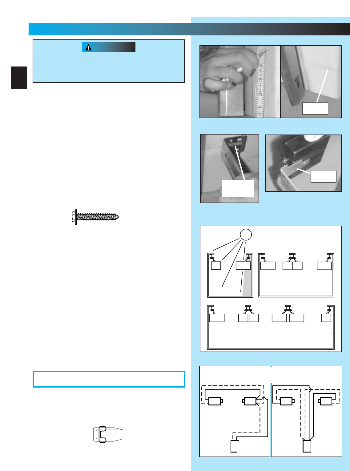
2. Mounting STB source and sensor.
•If garage has only one garage door.
–Determine which side of garage receives
most direct sunlight (Fig. 3-4).
–Red LED should always be on sunny side
whenever possible (Fig. 3-4).
•For multiple doors.
–Preventing crossed signals is critical.
–Place source and sensor modules on
adjacent doors facing in opposite directions
(Fig. 3-4).
NOTE: To help prevent interference from sun, STB
sensors (green LED) may be placed further away
from the door opening where they will spend more
time in shadows.
•Slide source/sensor onto tongue of bracket
until it clicks into place (Fig. 3-3).
3. Wiring.
•Route wire using either method shown(Fig. 3-5).
•Securely fasten wires to wall as you go.
–Use insulated staples (included).
–Staples should be snug only.
WARNING
NOTE: The operator will not close the door
automatically unless the Safe-T-Beam®System
is installed.
1. Mounting brackets.
•Mark both sides of garage door frame or wall 5”
above floor (Fig. 3-1).
•Hold bracket against door frame or wall.
–Check if brackets extend out from wall far
enough, so tongue of bracket is beyond door,
tracks or any door hardware.
–If not:
a. STB bracket extensions are available at
local dealer.
b. Blocks of wood, etc. may be substituted
for extensions.
•Center bracket on your mark (Fig. 3-2).
•Fasten each with 2 screws [127 ].
There should be no electrical power to the
operator while installing Safe-T-Beam®System
wires. If you have plugged in the power cord
—UNPLUG IT NOW.
FIG. 3-1 Mark door frame.
FIG. 3-2
Mount brackets.
F
IG. 3-3
Attaching STB’s to brackets
.
(See directions on next page and
Figure 3-4 before attaching.)
tongue
mark
center of
bracket
#10-16 x 1-1/4”
FIG. 3-5 STB wiring methods.
Sensor
Source
Red
Green
Power
Head
Sensor
Source
Red
Green
Power
Head
AB
Dashed Line = striped wire
Solid Line = white wire
FIG. 3-4 STB locations.
SUN
ONE DOOR
GARAGE
THREE DOOR
GARAGE
RED
LED
RED
LED
GREEN
LED
RED
LED GREEN
LED
GREEN
LED GREEN
LED RED
LED
RED
LED
RED
LED
GREEN
LED GREEN
LED
TWO DOOR
GARAGE
18
3...
SAFE-T-BEAM®INSTALLATION
FOR HELP-1.800.354.3643 OR GENIECOMPANY.COM
OPEN RED PARTS BAG
[128]
[127]
Insulated staple
CAUTION
FIG. 3-8 (ProMax)
Attachments at
power head.
•Make wire attachments at STB’s.
–Splitting and stripping wire ends to be
connected as shown (Fig. 3-6).
–Loosen terminal screws.
–Insert wire under flat plate and tighten screw. It
does not matter which wire, white or striped,
goes on which terminal (Fig. 3-7).
•Make wire attachments at power head.
–For ProMax. STB’s are connected to terminals
#2 and #3 on power head (Fig. 3-8).
–For Stealth. STB’s are connected to
terminals #3 and #4 on power head (Fig. 3-8).
4. Check the following.
•Insure that no part of door or its hardware is in
path between lenses of source and sensor.
•Insure that tops of lenses are between 5”-6”
above the floor (Fig. 3-9). The brackets are
flexible and can be adjusted slightly if needed.
NOTE: STB alignment check must be performed
following connection to electrical power (see page 21).
DO NOT PLUG IN YET!
Staples which are too tight can cut or pinch wires.
Cut or pinched wires can cause the STB System
to stop working. When using the insulated
staples, make sure you fasten them only as tightly
as needed to hold the wire snugly.
FIG. 3-7
Attachments
at STB.
FIG. 3-9 Check lens height.
top edge of lens between
5”- 6”above floor.
FIG. 3-6
Splitting and
stripping.
2
3
FIG. 3-8 (Stealth)
Attachments at
power head.
3
4
19
STB SELF-DIAGNOSTIC TROUBLESHOOTING
ON ON NORMAL OPERATION NONE REQUIRED
OFF OFF 1.POWER HEAD NOT POWERED
2.WIRING FROM POWER HEAD BAD
1.CHECK BREAKERS, FUSES, PLUGS
2.CHECK WIRING FOR OBVIOUS SHORTS
OFF ON 1.WIRING TO SOURCE MISSING OR BAD
2.POWER HAS BEEN INTERRUPTED
1.CHECK WIRING
2.REMOVE POWER AND REAPPLY
2 BLINKS, PAUSE (REPEAT) ON 1.BEAM NOT ALIGNED 2. BEAM OBSTRUCTED
3.SENSOR DEFECTIVE
1.CHECK ALIGNMENT 2. CHECK FOR OBSTRUCTION
3.CALL CUSTOMER SERVICE
1.WIRE TO SENSOR MISSING OR BAD
2.SENSOR DEFECTIVE
1.CHECK WIRING
2.CALL CUSTOMER SERVICE
OFF
ON 1.SENSOR RECEIVING INTERFERENCE 1.
ATTEMPT TO DETERMINE SOURCE OF INTERFERENCE
2.CALL CUSTOMER SERVICE
ON 1.SOURCE NOT SENDING PULSES
2.SOURCE DEFECTIVE
1.CALL CUSTOMER SERVICE
2.CALL CUSTOMER SERVICE
NOTE: IF OPERATING PROBLEM EXISTS, THE DOOR CAN BE CLOSED IF YOU: 1. DISCONNECT THE STB SYSTEM FROM THE OPERATOR AND 2. HOLD WALL CONTROL BUTTON
DOWN UNTIL DOOR IS CLOSED. (REMOTE CONTROL & WIRELESS KEYPAD WILL NOT WORK WITHOUT STB)
SOURCE (RED LED)SENSOR (GREEN LED)INDICATED CONDITION REQUIRED ACTION
2 BLINKS, PAUSE (REPEAT)
3 BLINKS, PAUSE (REPEAT)
4 BLINKS, PAUSE (REPEAT)
CUSTOMER SERVICE: 1.800.354.3643 or www.geniecompany.com
Safe-T-Beam®Alignment Check
After turning the electrical power on, if the
STB’s are not in proper alignment, the red
LED (Source) will blink continuously.
To correct the problem – the brackets are
flexible and can be adjusted slightly to bring
the system into alignment.
When the STB’s are in alignment the red LED
will stop blinking and stay on.
CAUTION
WARNING
Wall console
Wall button
OR
Fig. 4-2
#6 x 1”
pan head screws
Fig. 4-3
MORE
T
MENT
OPEN
PUSH
LIMITS
TO SET
G4
Y3
B2
W1
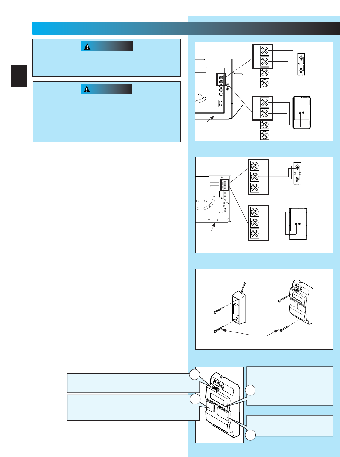
1. Run wire from power head to wall control.
•Place the wall control:
–In sight of door.
–At least 5 feet from floor, so small children can
not reach it.
–Away from moving parts of door and
door hardware.
•Use staples to fasten wire to ceiling and wall.
2. Remove 1/2”insulation from each wire
(Fig. 3-6)(pg. 19).
3. Attach wires to terminals (Stealth Fig. 4-1a)
(MAX Fig. 4-1b).
•Loosen, but Do Not remove screw from terminal.
For Stealth.
–Connect striped wires to terminal “2”on power
head and “B”on wall control.
–Connect white wire to terminal “1”on power
head and “W”on wall control.
For MAX.
–Connect striped wires to terminal “1”on power
head and “B”on wall control.
–Connect white wire to terminal “2”on power
head and “W”on wall control.
4. Mount wall control (Fig. 4-2).
•Use two pan head screws.
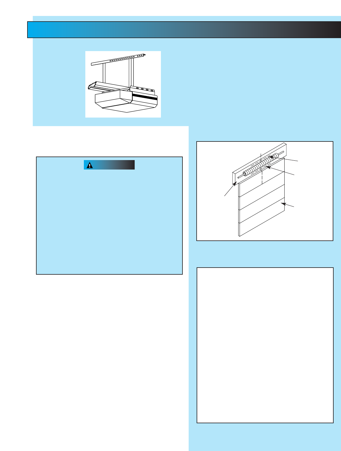
5. Mount entrapment warning label.
•Remove protective backing and stick near
wall control.
•Use tacks or staples to permanently mount Label.
•
Make sure everyone reads and follows WARNINGS.
NOTE: Additional wall controls are available from your
dealer. ONLY ONE OF YOUR WALL CONTROLS MAY BE THE
LIGHTED TYPE. If you have a lighted wall control, all your
additional controls must be un-lighted. More than one
lighted wall control per operator will cause a malfunction.
Power cord must be unplugged before attaching
wires. Be sure wire ends do not touch each other
or other terminals.
•Use of any other wall control will cause the
light not to work and could cause door to
operate by surprise.
•Cut or pinched wires can cause door operator
to malfunction. Drive staples just tight enough
to hold wire.
Fig. 4-1a
1
2
3
4
W
B
BW
White
Striped
Wall
console
terminals
Wall
button
terminals
Power head
terminals
Back view
Back view
1
2
3
4
White
Striped
OR
Power
head
ferminals
Rear view of
power head
Fig. 4-1b
NEC
CLASS 2
1
2
3
4
5
6
MORE
FORCE
PUSH
BUTTON
SAFETY
BEAM
LIMIT
SET
OPEN
FORCE
CLOSE
FORCE
RADIO
SIGNAL
LEARN
CODE
COM
DO NOT
PUSH
LIMIT SET
UNLESS
DOOR IS
ATTACHED
NOTE:
USE ONLY WITH
SERIES II CONTROLS
CLOSE
MORE
OPEN
MORE
OSE OPEN
LIMIT ADJUSTMENT
U.S. Patent No. 5,243,784
5,221,869
CSS
1
2
3
W
B
BW
Striped
White
Wall
console
terminals
Wall
button
terminals
Power head
terminals
power head
terminals
Back view
Back view
Front view of
power head
CSS
1
2
3
Striped
White
EITHER
20
4...
WALL CONTROL INSTALLATION
FOR HELP-1.800.354.3643 OR GENIECOMPANY.COM
Independent Light Control
–
Controls door operator lights from inside garage
–
Energy-Saver shut-off turns off light 5 minutes after
door activation
Vacation Locking Switch
–LOCK disables controls after door is completely closed
–UNLOCK allows controls to work normally
Lighted Button
–
Shows system is powered
–
Lights when Security Lock
Switch is in UNLOCK position
–
Goes out when Security Lock
Switch is in LOCK position
Door Control Button
–
Open and closes door from
inside garage
1
4
3
2
1. Disconnect the power cord from the branch
circuit mains.
2. Remove bottom cover from power head.
•Remove four (4) hex head screws from front
and rear covers.
•Slide bottom cover off.
3. Remove existing power cord from power head.
•Disconnect three power cord wires.
•Remove and discard power cord.
•Remove 7/8”diameter knock-out plug.
•Install a suitable entrance bushing.
4. Install permanent wiring to power head.
For Stealth—connect permanent wiring to
internal terminal block.
•Connect white supply line to silver terminal.
•Connect black supply line to brass terminal.
•Connect ground wire to green wire location
(GROUND).
For ProMax—connect permanent wiring.
•Make connections with UL recognized wire nuts.
•Connect white supply line to white wire.
•Connect black supply line to black wire.
•Connect ground wire to green wire location
(GROUND).
•Wires inside operator are to be a minimum of
6 inches.
5. Replace power head bottom cover.
•Replace and tighten four (4) hex head screws.
NOTE:
Circuit boards are light sensitive.
Make sure
cover is on power head before
operation.
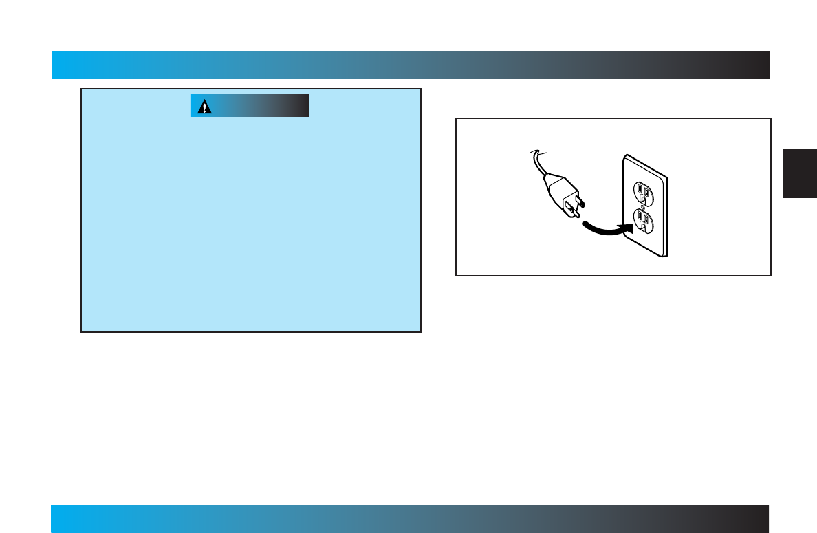
1. Check local building codes.
•Some building codes require direct wiring to a
branch circuit. If direct wiring is NOT required,
plug door operator into grounded outlet
(Fig. 6-1).
2. Return to Section 3 for SAFE-T-BEAM®System
alignment and troubleshooting.
NOTE: If permanent wiring is required, have a
professional electrician install circuit and wire
door operator.
Fig. 5-1
Operator
power cord
Grounded
outlet
To reduce the risk of electrical shock, this equipment
has a grounding type plug that has a third
(grounding) pin. This plug will only fit into a grounding
type outlet. If the plug does not fit into the outlet,
contact a qualified electrician to install the proper
outlet. Do Not change the plug in any way. The door
operator must be properly grounded to prevent
personal injury and damage to the components.
The ELECTRICAL POWER to the door operator
MUST BE TURNED OFF when power head cover is
removed. Electrical power must remain off while
making electrical connections.
5...
CONNECT OPERATOR TO POWER
FOR HELP-1.800.354.3643 OR GENIECOMPANY.COM
21
PERMANENT WIRING INSTRUCTIONS FOR ELECTRICIAN
WARNING
WARNING
Fig. 6-1
MORE MORE
LIMIT ADJUSTMENT
CLOSE OPEN
PUSH
LIMITS
TO SET
4
3
2
1
CLASS 2
NEC
OPEN
CLOSE
TO SET
LIMITS
PUSH
OR
NEC
CLASS 2
1
2
3
4
5
6
MORE
FORCE
PUSH
BUTTON
SAFETY
BEAM
LIMIT
SET
OPEN
FORCE
CLOSE
FORCE
RADIO
SIGNAL
LEARN
CODE
COM
DO NOT
PUSH
LIMIT SET
UNLESS
DOOR IS
ATTACHED
NOTE:
USE ONLY WITH
SERIES II CONTROLS
CLOSE
MORE
OPEN
MORE
CLOSE OPEN
LIMIT ADJUSTMENT
U.S. Patent No. 5,243,784
5,221,869
5
6
MORE
FORCE
LIMIT
SET
OPEN
FORCE
CLOSE
FORCE
PUSH
LIMIT SET
UNLESS
DOOR IS
ATTACHED
PRO MAX
Before starting main limit switch settings, LOCK
carriage onto rail assembly (See emergency
release tag).
1. Raise the door until the carriage engages with
the inner-slide/bullet.
2. Set “OPEN”limit switch (Fig 6-1).
•Locate limit set switch on back of power head.
•Push and hold limit set switch until door moves
to the fully open position.
–release the limit set switch.
–“OPEN”limit switch is set.
NOTE: If door stops and refuses to move up, adjust
“OPEN FORCE”(See Section 7-FORCE
ADJUSTMENT) and then repeat setting limit switch.
3. Set “CLOSE”limit switch (Fig. 6-1).
•Push and hold limit set switch until door contacts
the ground and stops.
–release limit set switch.
–“CLOSE”limit is set.
NOTE: If door stops and refuses to move down,
adjust “CLOSE FORCE”(See Section 7-FORCE
ADJUSTMENT) and then repeat setting limit switch.
NOTE: Do Not push the limit set switch again, your
limits are set. Slight adjustment may be needed later
(See Section 8-FINE LIMIT SWITCH ADJUSTMENTS).
Door opens rapidly.
•Keep path clear.
•Position ladder to the side of power head so it
is clear of all moving parts of door and
operator.
Set door operator so minimum force is needed
to operate door.
STEALTH
6...
MAIN LIMIT SWITCH SETTINGS
FOR HELP-1.800.354.3643 OR GENIECOMPANY.COM
22
NEC
CLASS 2
1
2
3
4
5
6
MORE
FORCE
PUSH
BUTTON
SAFETY
BEAM
LIMIT
SET
OPEN
FORCE
CLOSE
FORCE
RADIO
SIGNAL
LEARN
CODE
COM
DO NOT
PUSH
LIMIT SET
UNLESS
DOOR IS
ATTACHED
NOTE:
USE ONLY WITH
SERIES II CONTROLS
CLOSE
MORE
OPEN
MORE
CLOSE OPEN
LIMIT ADJUSTMENT
U.S. Patent No. 5,243,784
5,221,869
WARNING
CONTACT REVERSE
Fine adjustments for limit switches (see Section 8)
MUST BE completed before starting CONTACT
REVERSE.
•Open door, use wall control.
•Place a 2 by 4 board laid flat in center of doorway.
•Close door.
•Door MUST stop and reverse to open position. If it
does not, repeat fine adjustments for down limit
switch and “CLOSE FORCE”adjustment until the
door will reverse to the open position.
NOTE: Set minimum force required to make door close.
If door does not reverse, decrease “CLOSE FORCE”
until door reverses.
During the following steps, the motor protector may
open. Wait about 20 minutes for protector to reset.
NOTE:
Use wall control to run door to the fully
CLOSED position before starting “OPEN FORCE”
adjustment.
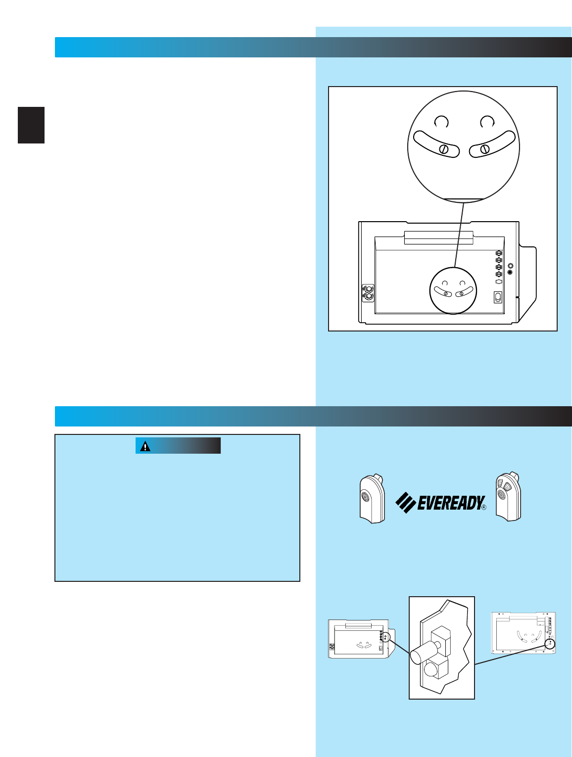
1. Adjust the “OPEN”Force (Fig. 7-1).
•Locate screw on back of power head marked
“OPEN FORCE.”
•Gently turn screw counterclockwise until it stops.
NOTE: Little effort is required to turn adjusting screw.
•Operate door using wall control.
•If door does not completely open, turn “OPEN
FORCE”screw clockwise slightly.
•Activate door using wall control.
•Repeat force adjustment until door will
completely open.
NOTE: Set minimum force required to make door open.
•Close door, use wall control.
2. Adjust the “CLOSE FORCE”(Fig. 7-1).
Use wall
control to run door to the fully OPEN position
before starting “CLOSE FORCE”adjustment.
•Locate screw on back of power head marked
“CLOSE FORCE.”
•Gently turn screw counterclockwise until it stops.
NOTE: Little effort is required to turn adjusting screw.
•Operate door using wall control.
•If door does not completely close, turn “CLOSE
FORCE”screw clockwise slightly.
•Operate door using wall control.
•Repeat force adjustment until door will
completely close.
NOTE: Set the minimum force required to make the
door close. Smaller the number the smaller the
force.
3. (Fig. 7-2)
Adjust your door operator so that minimum
force is needed to operate door.
Position ladder to the side of the power head so
that it is clear of all moving parts of the power
head, rail assembly and door.
Fig. 7-2
1 1/2”Object
(or a 2 x 4
laid flat)
CONTACT REVERSE
Fig. 7-1
MORE MORE
LIMIT ADJUSTMENT
CLOSE OPEN
PUSH
LIMITS
TO SET
4
3
2
1
CLASS 2
NEC
OPEN
CLOSE
OR
6
MORE
FORCE
LIMIT
SET
OPEN
FORCE
CLOSE
FORCE
RADIO
SIGNAL
LEARN
CODE
PRO MAX
STEALTH
7...
FORCE ADJUSTMENT
FOR HELP-1.800.354.3643 OR GENIECOMPANY.COM
23
WARNING
During the following steps, the motor protector may
open. Wait about 20 minutes for protector to reset.
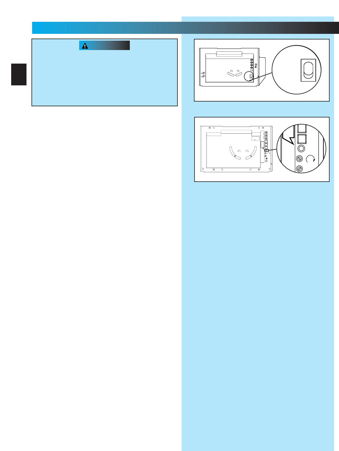
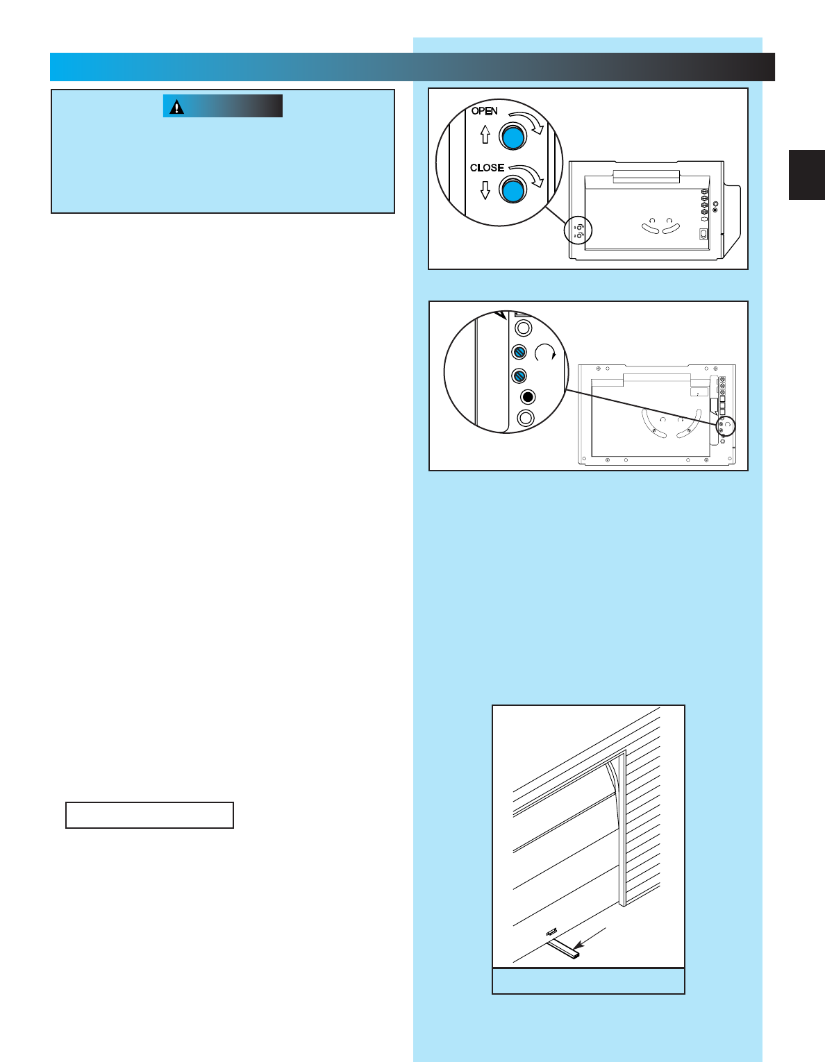
1. Adjusting the “OPEN”limit switch (Fig. 8-1).
•Run door to open position by pushing wall control.
•Locate curved “OPEN”limit adjustment slot on
back of power head.
•Look into slot for pinion screw.
•Insert a screwdriver and turn pinion screw.
–clockwise to open more.
–counterclockwise to open less.
2. Test door operator. Use wall control to run
door open and close.
3. Repeat step as necessary to properly set
“OPEN”limit switch.
4. Adjust the “CLOSE”limit switch (Fig. 8-1).
•Run door fully closed by pushing wall control.
•Locate curved “CLOSE”limit adjustment slot on
back of power head.
•Look into slot for pinion screw.
•Insert a screwdriver and turn pinion screw.
–counterclockwise to close more.
–clockwise to close less.
5. Test door operator. Use wall control to run door
open and close
6. Repeat step as necessary to properly set
“CLOSE”limit switch
7. Perform CONTACT REVERSE
Moving door can cause serious injury or death
•
Keep people clear of opening while door is moving.
•Do Not allow children to play with remote controls.
If safety reverse does not work properly:
•Close door and disconnect operator using
emergency release.
•Do not use door operator or remote controls
•Refer to door and door operator owner’s
Manuals before attempting any repairs
NOTE: Factory sets different codes for each remote
control.
Remote controls will not work if STB’s malfunction
When programming remote control keep at least 24
inches away from antenna.
1. Program one-button remote (Fig. 9-1)
•Locate learn code button and learn indicator on
power head.
–Remove lens cover on back of power head.
•Press and release learn code button on
power head.
–LED on power head blinks 2 times per second.
One-Button Remote Control* Multi-Button Remote Control*
Complete with
Battery
Actual picture may vary by model
NEC
CLASS 2
1
2
3
4
5
6
MORE
FORCE
PUSH
BUTTON
SAFETY
BEAM
LIMIT
SET
OPEN
FORCE
CLOSE
FORCE
RADIO
SIGNAL
LEARN
CODE
COM
DO NOT
PUSH
LIMIT SET
UNLESS
DOOR IS
ATTACHED
NOTE:
USE ONLY WITH
SERIES II CONTROLS
CLOSE
MORE
OPEN
MORE
CLOSE OPEN
LIMIT ADJUSTMENT
U.S. Patent No. 5,243,784
5,221,869
MORE MORE
LIMIT ADJUSTMENT
CLOSE OPEN
PUSH
LIMITS
TO SET
4
3
2
1
CLASS 2
NEC
STEALTH PRO-MAX
Fig. 9-1
24
8...
FINE LIMIT SWITCH ADJUSTMENT
FOR HELP-1.800.354.3643 OR GENIECOMPANY.COM
MORE MORE
LIMIT ADJUSTMENT
CLOSE OPEN
PUSH
LIMITS
TO SET
4
3
2
1
CLASS 2
NEC
LIMIT ADJUSTMENT
CLOSE
MORE
OPEN
MORE
Fig. 8-1
9...
REMOTE CONTROLS
*Remotes vary depending on model. Your operator will
have one or the other.
(continued on next page)
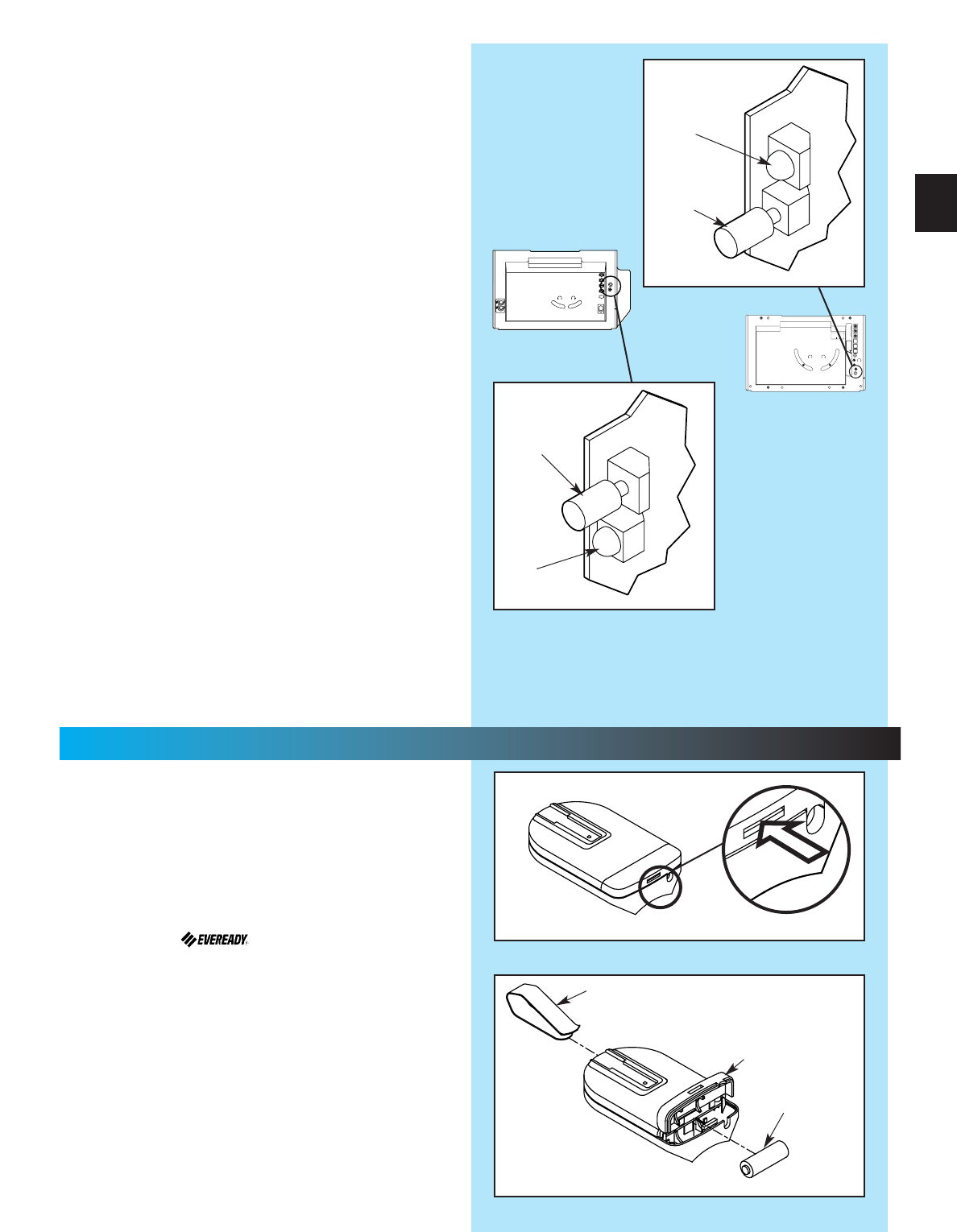
1. Turn remote control upside down (Fig. 10-1)
2. Battery replacement (your remote control is
battery powered).
•Gently push straight IN on tab as shown
(Fig. 10-1).
–use ball point pen, coin or small screwdriver.
–battery cover snaps open.
•Install new battery in same position.
–use A23, 12 Volt battery.
3. Attach visor clip to remote control (Fig. 10-2)
•Slide visor clip into back of case until it snaps
into place.
4. Remote control operation
•Point remote control at the garage door and
press the button. Door will move.
•Press remote control button again and door
will stop.
•Press remote control button again and the door
will move the other way. The door automatically
stops at the end of the open or close cycle.
Fig. 10-1
Fig. 10-2
Visor clip
Battery
Battery
cover
+
–
Fig. 9-1
Learn
code
button
Radio
signal
indicator
MORE MORE
LIMIT ADJUSTMENT
CLOSE OPEN
PUSH
LIMITS
TO SET
4
3
2
1
CLASS 2
NEC
NEC
CLASS 2
1
2
3
4
5
6
MORE
FORCE
PUSH
BUTTON
SAFETY
BEAM
LIMIT
SET
OPEN
FORCE
CLOSE
FORCE
RADIO
SIGNAL
LEARN
CODE
COM
DO NOT
PUSH
LIMIT SET
UNLESS
DOOR IS
ATTACHED
NOTE:
USE ONLY WITH
SERIES II CONTROLS
CLOSE
MORE
OPEN
MORE
CLOSE OPEN
LIMIT ADJUSTMENT
U.S. Patent No. 5,243,784
5,221,869
STEALTH
PRO-MAX
•Press and release a remote control button.
–LED on power head stops blinking.
•Press and release same remote button again.
–LED goes out. Remote is now programmed.
2. Program multi-button remote control
•Repeat step 1 (“program one-button remote” for
each button).
NOTE: Each button on a multi-button remote control
is for a different operator.
3. Operate remote control
•Point remote control at door
–Door moves
•Press button again
–Door stops
•Press button again
–Door reverses
NOTE: Door automatically stops at end of open or
close cycle.
4. Erasing all receiver memory
•Press and hold learn code button on
power head
–10 seconds or until light goes out
–Memory is erased
•Program door operator again
•Press remote control button once within
30 seconds
–LED on power head stays lit
•Press remote control button again
–LED on power head goes out and remote
control is programmed
NOTE: If LED blinks approximately 4 times per
second, programming has stopped. If programming
stops, repeat above steps.
Radio
signal
indicator
Learn
code
button
25
10...
BATTERY / VISOR CLIP INSTALLATION
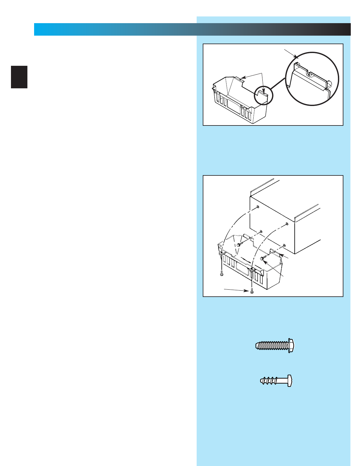
1. Install light bulb(s) into socket(s).
Do Not use short neck bulb(s).
•Use bulb(s) rated for:
–rough service.
–vibration.
–appliances.
•100 watt maximum.
2. Bend two (2) slotted tabs up. This will activate
the ”living hinge”of the lens (Fig. 11-1).
NOTE: The following steps use the screws from the
Blue Parts Bag that were set aside earlier.
3. Start two (2) No. 8 x 3/4”hex head screws into
bottom holes of panel (Fig. 11-2).
•Slide slotted tabs up behind hex head screws.
•Tighten hex head screws.
4. Align lens holes and holes of panel.
•Insert and tighten a No. 8 x 5/8”pan head
screw into each round lens hole and tighten,
NOTE: Screw heads fit completely into recess of
lens tab.
Fig. 11-2
Fig. 11-1
Pan head
screws
Bend tabs up
Slotted tabs
Bend tabs up (2)
Hex head
screws
11...
LIGHT BULB AND LENS INSTALLATION
FOR HELP-1.800.354.3643 OR GENIECOMPANY.COM
26
[10]
[10]
[9]
Hex Head Screw
No. 8 x 3/4”
Pan Head
Phillips Screw
No. 8 x 5/8”
[9]
MONTHLY MAINTENANCE
DOOR SPRINGS and DOOR HARDWARE
•Do not operate garage door automatically or
manually if springs are broken. CONTACT A
PROFESSIONAL FOR SERVICE.
•Oil door rollers, bearings, and hinges monthly.
Use silicone lubricant or light oil.
DOOR BALANCE
•Close door. Pull red emergency release knob
down and toward power head to release door
from rail assembly.
•Raise door manually approximately 3 feet. Door
should stay in that position. If door moves, HAVE
DOOR SERVICED BY A PROFESSIONAL.
•Close door. Pull red emergency release knob to
reattach door to rail/channel assembly.
CONTACT REVERSE
•Close door on a 2 by 4 board laid flat on the floor
in the center of the garage doorway.
•Close door by using wall button or remote control.
•If door fails to reverse on contact with the board,
see Section 7-CONTACT REVERSE.
•If operator still fails, replace operator or HAVE
THE DOOR SERVICED BY A PROFESSIONAL.
Safe-T-Beam®STB SYSTEM
•Use self-diagnostic Safe-T-Beam®System
troubleshooting information to maintain safe
operation.
(See Section 3-STB SYSTEM INSTALLATION.)
IMPORTANT
SAFETY
INSTRUCTIONS
1READ AND FOLLOW ALL INSTRUCTIONS.
2Never let children operate or play with the Door
Controls. Keep the Remote Control away
from children.
3Always keep the moving door in sight and away
from people and objects until the door is completely
closed. NO ONE SHOULD CROSS THE PATH OF
THE MOVING DOOR.
4NEVER GO UNDER A STOPPED, PARTIALLY
OPEN DOOR.
5Test Opener monthly. The door MUST reverse on
contact with a 1-1/2" high object (or a 2" x 4" board
laid flat) at the center of the doorway on the floor.
After adjusting either the Force or the Limit of travel,
retest the Door Opener. Failure to adjust the
Opener properly may cause severe injury or death.
6When possible use the Emergency Release only
when the door is closed. Use caution when using
this Release with the door open. Weak or broken
springs are capable of increasing the rate of door
closure and increasing the risk of severe injury
or death.
7KEEP GARAGE DOORS PROPERLY BALANCED.
See Owner's Manual. An improperly balanced door
increases the risk of severe injury or death. Have a
Genie Factory Authorized Dealer make repairs to
cables, spring assemblies, and other hardware.
8SAVE THESE INSTRUCTIONS.
WARNING
To reduce the risk of
severe injury or death:
27
MAINTENANCE
FOR HELP-1.800.354.3643 OR GENIECOMPANY.COM
Transmitters comply with all United States and Canadian legal
requirements as of the date of manufacture. No warranty is made that
they comply with all legal requirements of any other jurisdiction. If
transmitters are to be used in another country, the importer must
determine compliance with any local laws and regulations which may
differ from United States and Canadian requirements prior to use.
Los transmisores cumplen con todas las reglamentaciones legales de
los Estados Unidos y del Canad , en la fecha de fabricaci n. Ninguna
garant a se da que cumplan con todas las reglamentaciones legales de
ninguna otra jurisdicci n. Si los transmisores se van a utilizar en otro
pa s, el importador debe determinar si cumplen con las
reglamentaciones y leyes locales que puedan ser diferentes a las
reglamentaciones de los Estados Unidos y del Canad , antes de usar
los mismos.
Sendeger te entsprechen allen gesetzlichen Bestimmungen in den USA
und Kanada zum Zeitpunkt der Herstellung. Wir bernehmen keine
Gew hrleistung f r die Einhaltung aller gesetzlichen Bestimmungen in
anderen L ndern. Sollen Sendeger te in anderen L ndern eingesetzt
werden, so muss der Importeur vor dem Gebrauch sicherstellen, dass
die Sendeger te auch solchen lokalen Bestimmungen entsprechen,
welche von den Bestimmungen der USA und Kanadas abweichen.
Les metteurs sont conformes la r glementation am ricaine et
canadienne compter de leur date de fabrication. Aucune garantie
n est stipul e indiquant qu ils sont conformes toutes les prescriptions
juridiques d autres autorit s. Si les metteurs sont utilis s dans d autres
pays, il incombe l importateur d en d terminer leur conformit aux lois
et r gles locales pouvant diff rer de celles des tats-Unis et du Canada
avant toute utilisation desdits metteurs.
Transmitter Compliance Statement

CAUTION
Door starts for no reason. Check staples on wire from power head to wall control. If they cut into insulation, they can short wires.
If wire is cut, replace it.
Was a remote control lost or stolen? Erase all remote control codes from receiver memory and reprogram.
Wall control button sticking. Check operation of buttons.
Door starts down, then
stops before it’s closed.
Check CLOSE limit switch setting (See Section 8)
Check for shorted wires
Door starts down, then
stops and goes back up.
Check force adjustment (See Section 7).
Check CONTACT REVERSE (See Section 7).
Check for light beam obstruction or misalignment of Safe-T-Beam®(See Section 3).
Check STB self-diagnostic code.
Door will only run closed. Check OPEN limit switch for short and proper wiring.
Check force adjustment (See section 7).
Check for broken door spring.
Door will only run open. Check Safe-T-Beam®System(See section 3).
Check CLOSE limit switch for short and proper wiring.
Check force adjustment (See Section 7).
Remote control has
less than 25 feet
operating range.
Relocate remote control inside car.
Point remote control at door.
Replace battery.
Do Not attempt to retune remote controls.
Door starts up, but
stops before it’s
completely open.
Be sure door is in good repair, properly lubricated and balanced.
Check OPEN limit switch setting (See section 8).
Check force adjustment (See section7).
Check for broken door spring.
Operator runs, but door
does not move.
Make sure carriage is engaged.
Check force adjustment (See Section 7).
Operator works from wall
control, but not from
remote control.
Program remote control code into receiver memory (See section 9).
If one remote control works and another does not, check battery, remote control type (Series II ) and
frequency of non-working unit (See section 9) .
Noisy operation. Be sure all fasteners are tight.
Be sure door is in good repair, properly lubricated and balanced (See Monthly Maintenance section).
STB System malfunction. Use self-diagnostic STB System troubleshooting information to maintain safe operation
(See section 3).
Use this guide to correct problems with your door
operator. If these solutions do not work,
call Customer Service.
Use only with included SERIES II wall control
Use of any other wall control can cause the door
to operate unexpectedly and the light not to work.
PROBLEM SOLUTIONS
Operator does not run
from wall control.
Check lock switch on wall console (See section 4).
Check the power source.
•Plug a lamp into outlet used for power head. If lamp works, power source is OK. If not, check fuse
or circuit breaker.
•If power is OK:
-
Check connections at power head terminals.
-
Check connections at wall control.
-
Motor protector may be open. Wait about 20 minutes for protector to reset.
Lights will not go out. Check wiring.
Disconnect & reconnect wires on wall control.
Non-compatible wall control.
Innerslide jammed into
power head.
Remove motor cover and rotate opti-wheel.
TROUBLESHOOTING GUIDE
FOR HELP-1.800.354.3643 OR GENIECOMPANY.COM
28
CAUTION
(Stealth Motor)
Opening cover could cause electrical shock.
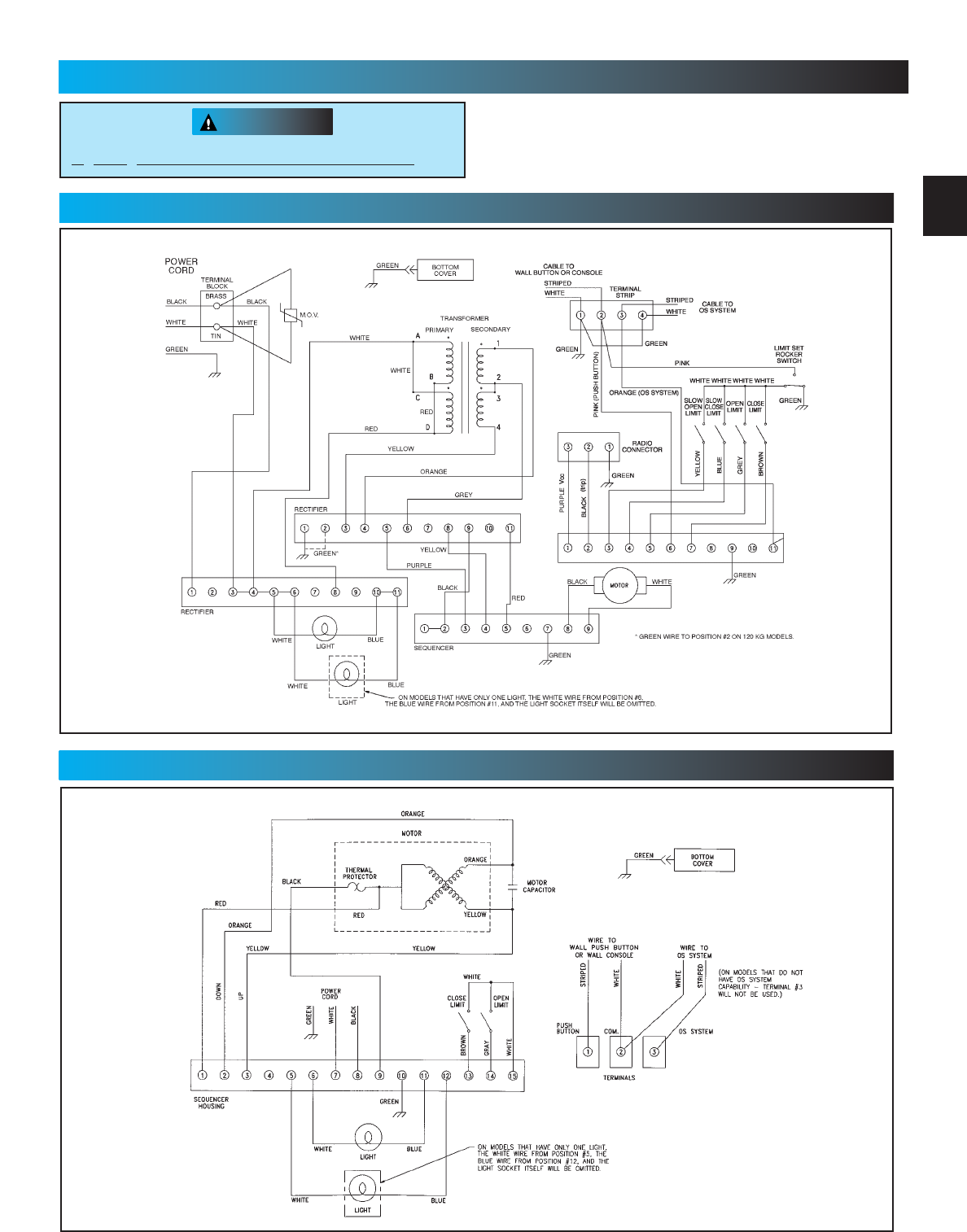
WIRING DIAGRAM
FOR HELP-1.800.354.3643 OR GENIECOMPANY.COM
29
(ProMax Motor)
30
No C.O.D. shipments. Please include check or money
order, made payable to The Genie Company. Do not
send cash.Allow 3-4 weeks for delivery.
1-800-354-3643. Please have part number and credit
card ready. Mail Order Form to: Genie Company,
Alliance, Ohio 44601.We accept Visa or Mastercard
on phone orders only.
Please add local sales tax if you reside in one of the states listed.
California, Connecticut, Florida, Georgia, Illinois, Indiana,
Maryland, Massachusetts, Michigan, New Jersey, New York,
Ohio, Tennessee, Virginia, Wisconsin
TOTAL ORDER $
SHIPPING & HANDLING $ 5.00
STATE SALES TAX $
GRAND TOTAL $
Pas d’expédition contre remboursement. Veuillez inclure un
chèque ou un mandat bancaire, le payable fait à The Genie
Company. N’envoyez pas d’argent comptant.Accordez de 3 à
4 semaines pour la livraison. 1-800-354-3643. Ayez sous la
main le numéro de la pièce et celui de la carte de crédit. Mettre
à la poste le arrngement à: Genie Company, Alliance, Ohio
44601.Nous acceptons les commandes par téléphone avec
paiement par carte de crédit Visa ou Mastercard.
Veuillez indiquer les taxes de vente locales si vous résidez dans l’un
des états répertoriés ci-dessous.
COMMANDE TOTALE $
MANUTENTION ET EXPÉDITION $ 5.00
TAXE DE VENTE $
TOTAL GLOBAL $
No se aceptan pedidos de pago contra entrega (COD).
Sírvase incluir su cheque o giro postal, la cuenta
pagadera hecha a The Genie Company. No envíe
dinero en efectivo.Concédanos 3 a 4 semanas para la
entrega. 1-800-354-3643. Sírvase tener listos los
números del modelo y de la tarjeta de crédito. Enviar
hacer un pedido de mercancia a: Genie Company,
Alliance, Ohio 44601.Aceptamos pedidos telefónicos de
Visa o Mastercard.
Sírvase agregar el impuesto de ventas local si usted reside en
uno de los siguientes estados:
TOTAL DEL PEDIDO $
FLETE Y MANEJO $ 5.00
IMPUESTO DE VENTAS ESTATAL $
GRAN TOTAL $
Ordering Instructions
Las Instrucciones que Ordenan
Instructions Commandant
3
DEFDEF
12
4 5 6
789
0
GHIGHI JKLJKL MNOMNO
PQRSPQRS
TUVTUV
WXYZWXYZ
9V9V
Garage Door Opener Accessories Order Form
Formulario de pedido de accesorios para abridores de puertas de garaje
Formulaire de commande des accessoires pour ouvre-porte de garage

INSTALLATION NOTES
FOR HELP-1.800.354.3643 OR GENIECOMPANY.COM
CONTACT NUMBERS
NAME COMPANY NUMBER
NAME COMPANY NUMBER
NAME COMPANY NUMBER
NAME COMPANY NUMBER
NAME COMPANY NUMBER
NAME COMPANY NUMBER
31

SAVE THESE INSTRUCTIONS
Manufactured under one or more of the following U.S. patents: 3,898,582 / 4,041,259 / 4,048,630 / 4,064,487 / 4,103,238 / 5,222,403
Other Patents applied for
22790 Lake Park Blvd. •Alliance, Ohio USA •44601
Customer Service
1. 800.35 GENIE
CORRESPONDENCE WITH FACTORY MUST INCLUDE DATE / MFG. NO.
(LOCATED UNDER LENS OF POWER HEAD)
__________________________________
FILL THIS IN AT TIME OF INSTALLATION FOR YOUR OWN RECORDS,
SO THAT IT WILL BE AVAILABLE IF YOU EVER NEED TO CALL US
Date Purchased______/______/_____________ Serial Number___________________________________
Operator Model___________________________ Remote Control Model____________________________
Dealer Name_________________________________________________________________________________
Dealer Address______________________________________________________________________________
City____________________________________ State___________________________ Zip________________
Or Visit Our Website
http://www.geniecompany.com
The Genie Company Professional Access Systems LIMITED WARRANTY
What is covered: Any defect in material and workmanship from personal, normal household use in accordance with the Owner’s Manual
For how long:
300 Series - Motor 5 years and all other parts 3 years.
500 Series - Motor Lifetime* and all other parts 5 years.
1200 Series - Motor Lifetime* and all other parts 5 years.
*Lifetime warranty = warranted for as long as you own your home.
Who gets the warranty: This warranty is limited to the consumer who originally purchased the product.
Geographic scope: This warranty applies only to Genie products purchased in the United States, Canada or Mexico.
What we will do: If your Genie product is defective, we will repair it or, at our option, replace it at no charge to you. If we repair your Genie product, we
may use new or reconditioned replacement parts. If we choose to replace your Genie product, we may replace it with a new or reconditioned one of the
same or similar design.
Limitations: IMPLIED WARRANTIES,INCLUDING THOSE OF FITNESS FOR A PARTICULAR PURPOSE AND MERCHANTABILITY (AN UNWRITTEN
WARRANTY THAT THE PRODUCT IS FIT FOR ORDINARY USE), ARE LIMITED TO ONE YEAR FROM THE DATE OF PURCHASE. GENIE WILL
NOT PAY FOR: LOSS OF TIME; INCONVENIENCE; LOSS OF USE OF YOUR GENIE PRODUCT OR PROPERTY DAMAGE CAUSED BY YOUR
GENIE PRODUCT OR ITS FAILURE TO WORK; ANY SPECIAL, INCIDENTAL OR CONSEQUENTIAL DAMAGES; OR ANY DAMAGES RESULTING
FROM MISUSE OR MODIFICATION OF YOUR GENIE PRODUCT.
Some states and provinces do not allow limitations on how long an implied warranty lasts or the exclusion of incidental or consequential damages, so
the above exclusions may not apply to you.
How to obtain warranty service: To obtain warranty service for your Genie product, you must provide proof of the date and place of purchase of
the product.
1. Do-It-Yourself-Service. Call the Genie Consumer Connection toll free at 1-800-354.3643 a Trained Genie representatives will assist you in diagnosing the
problem and will arrange to supply you with the required parts for do-it-yourself repairs. Trained service representatives are available Monday-Friday,
8:00 a.m. - 8:00 p.m., Eastern Time, and on Saturday, 11:00 a.m. to 5:00 p.m., Eastern Time (subject to holidays).
2. Service From Authorized Dealers. You also may obtain warranty service by calling the Genie Consumer Connection at 1.800.654.3643 before reaching
any agreement on service. If warranty service is provided by an authorized dealer, Genie will provide all required parts under warranty at no charge to
you, but the dealers are independent business people and may render a bench or service call charge for their services. Genie will not reimburse you or
otherwise be responsible for those charges.
We suggest that you retain your original packing material in the event you need to ship your Genie product. Be sure to include your name, address,
telephone number, proof of date and place of purchase and a description of the operating problem. After repairing or, at our option, replacing, your Genie
product, we will ship it to your home at no cost to you for parts and labor, but you will have to pay a minimum of $5.00 for shipping and handling
charges.
Your choice of any one of the above-described service options is your exclusive remedy under this warranty.
What this warranty does not cover: This warranty does not cover batteries (which are considered replaceable parts), installation, commercial use, defects
resulting from accidents, damage while in transit to our service location or damage resulting from alterations, misuse or abuse, lack of proper
maintenance, unauthorized repair or modification of the product, affixing of any attachment not provided with the product, fire, flood, or acts of God, or
other failure to follow the Owner’s Manual.
This warranty is the only one we will give on your Genie product, and it sets forth all our responsibilities regarding your Genie product. There are
no other express warranties.
State and province rights: This warranty gives you specific legal rights, and you may also have other rights which vary from state to state and province to
province.
