Geoforce 00GT0 Battery Powered GPS Tracking Device User Manual GT0 User Safety and Regulatory Guide
Geoforce Inc. Battery Powered GPS Tracking Device GT0 User Safety and Regulatory Guide
Geoforce >
User installation guide
GT0 User, Safety and Regulatory Guide
Guide Revision v130710a
Geoforce Inc.
Part Numbers: XS-GT0 and XS-GT0-W
July 2013

© Geoforce Inc., All Rights Reserved - version 130710a
2
GT0 User, Safety and Regulatory Guide | Geoforce Inc.
Table of Contents
GT0 Installation and Mounting Guide .................................................................................................................. 3
Mechanical Mounting ............................................................................................................................. 3
VHB Adhesive Mounting ......................................................................................................................... 3
Temporary and Fastener Free Mounting ................................................................................................ 3
GT0 Installation Drawing ...................................................................................................................................... 4
GT0 Mounting Hardware Examples ..................................................................................................................... 5
GT0 Maintenance ................................................................................................................................................. 6
Appendix A: Shipping and Transport Guidance ................................................................................................... 7
Transport Codes ...................................................................................................................................... 7
Lithium Battery Regulatory Information ................................................................................................. 7
Appendix B: Wireless/Environmental Regulatory Guidance ............................................................................... 8
RF Radiation Exposure Statement .......................................................................................................... 8
RF/Environmental Certifications ............................................................................................................. 8
Regulatory Notices .................................................................................................................................. 8
Appendix C: Safety Regulatory Guidance .......................................................................................................... 10
Hazloc Regulatory Notices .................................................................................................................... 10
Disposal Notices .................................................................................................................................... 10
Appendix D: General Notices ............................................................................................................................. 11
Appendix E: Supporting Documentation ........................................................................................................... 12
About Geoforce:
Geoforce is a privately held company that was founded in 2007 by oil and gas veterans who directly understood the dire need
for a better way to manage the high-value, mobile, remote, mission-critical assets of companies in the industry, but unlike
other oil hands, also had the technological know-how to fill that need.
Our intuitive, reliable and scalable technology, developed through our extensive oil and gas industry experience, provides you
with on-demand access to unique operational insight.
Geoforce provides asset management solutions utilizing a blend of GPS, RFID and other wireless technologies accessible via
customizable web-based software and enterprise grade web services. With the largest satellite asset tracking deployment in
the oilfield, Geoforce is proven to increase efficiency, transparency and profits.
© Geoforce Inc., All Rights Reserved - version 130710a
3
GT0 User, Safety and Regulatory Guide | Geoforce Inc.
GT0 Installation and Mounting Guide
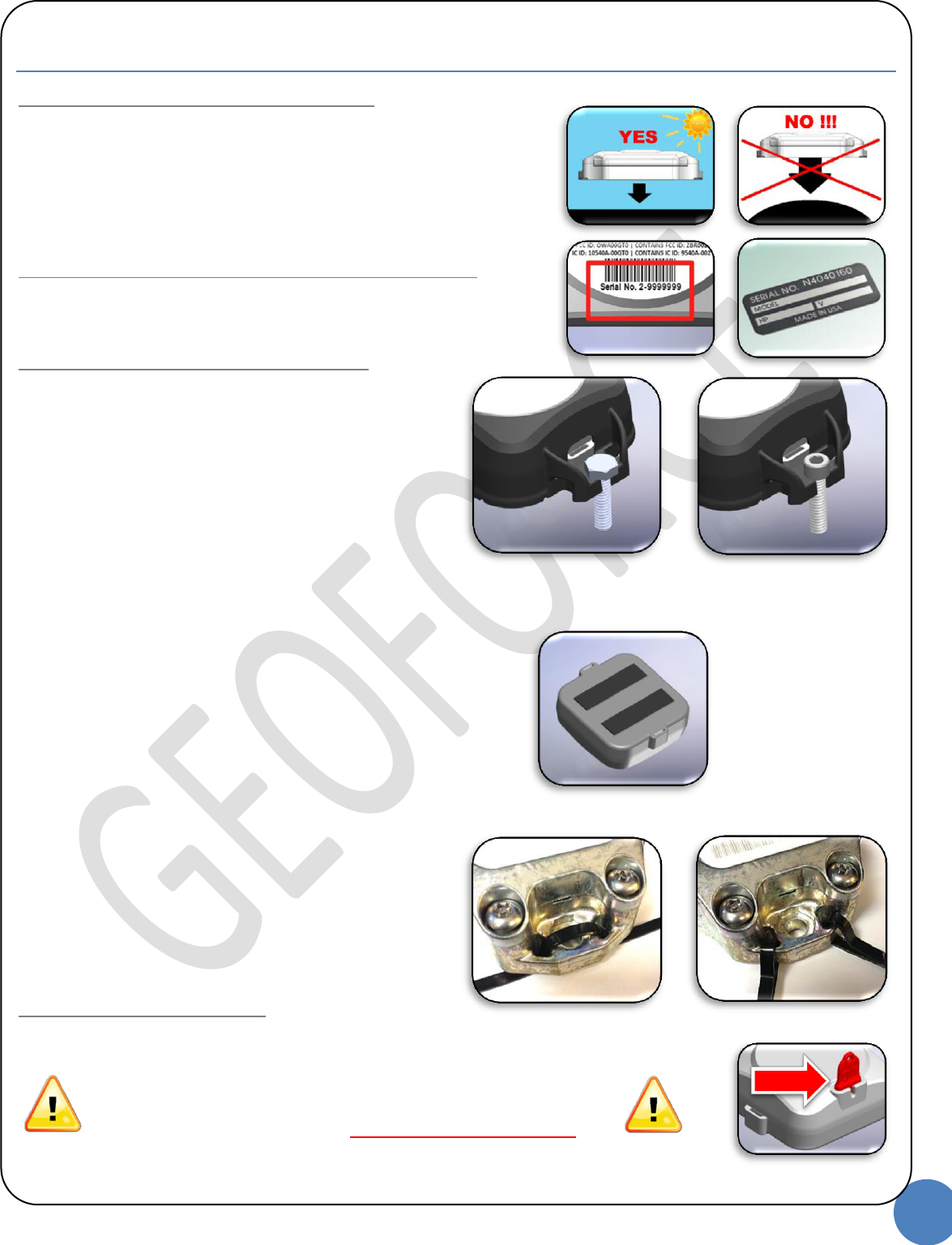
Step 1: Selecting a Mounting Location
To ensure ideal performance please consider the following:
1. Select a mounting location that provides the best view of the sky.
2. A horizontal mounting position (lying flat, facing skyward).
3. Mount on the flattest and hardest surface possible.
4. Select a mounting location that isolates the GT0 from damage.
5. Recommended mounting area size is 7”L x 4”W.
6. Thoroughly clean the mounting area.
Step 2: Record the Asset and GT0 Serial Numbers
1. Record the GT0 serial number.
2. Record the asset serial number (on which the GT0 was installed).
3. Send this information to your Geoforce account administrator.
Step 3: Selecting a Mounting Method
Mechanical Mounting
Utilizing the optional metal mounting bezel
Socket-Head Cap Screws (1/4” or 6mm bolt diameter)
For installations that can be drilled and tapped and do
not have access to the back side of the mounting
surface.
Hex-Head Cap Screws (1/4” or 6mm bolt diameter)
For installations that have access to the back side of
the mounting surface for securing a nut or bolt.
Self-drilling Sheet-metal Screws (1/4” or 6mm diameter)
For installations with thinner mounting surfaces where
a quicker install is needed.
It is recommended to use fasteners made of a material that
resists corrosion and environmental weathering such as
stainless steel.
VHB Adhesive Mounting
For installations that are isolated from abuse, extreme
weather and temperatures the GT0 has pre-installed pads
of VHB adhesive tape that can be used to “peel and stick”
to any clean surface above 50F (10C). Using VHB REQUIRES
installing to the Geoforce VHB installation guide process.
Temporary and Fastener Free Mounting
Metal straps and “Zip-ties” (1/4” or 6mm strap width)
For installations that are quick and temporary or that
may require a simple mechanical backup for VHB
installations.
Step 4: Initializing the GT0
Remove RED magnet lanyard from GT0 to begin service.
NOTE: IF YOU DO NOT REMOVE THE RED
MAGNET THE GT0 WILL NOT WORK!!!
Socket Head Cap Screw
Hex Head Cap Screw
Refer to the
Geoforce VHB
Installation
Guide!
VHB Adhesive Pads
Strapping or Zip-ties
© Geoforce Inc., All Rights Reserved - version 130710a
4
GT0 User, Safety and Regulatory Guide | Geoforce Inc.
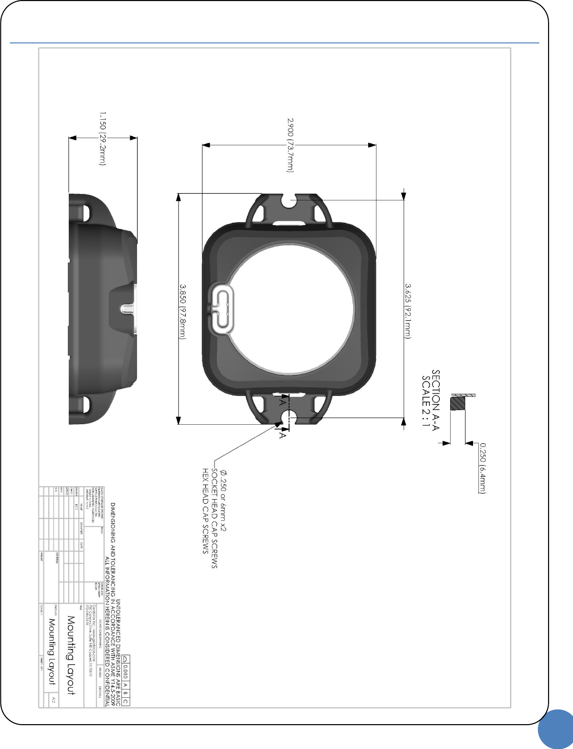
GT0 Installation Drawing
© Geoforce Inc., All Rights Reserved - version 130710a
5
GT0 User, Safety and Regulatory Guide | Geoforce Inc.
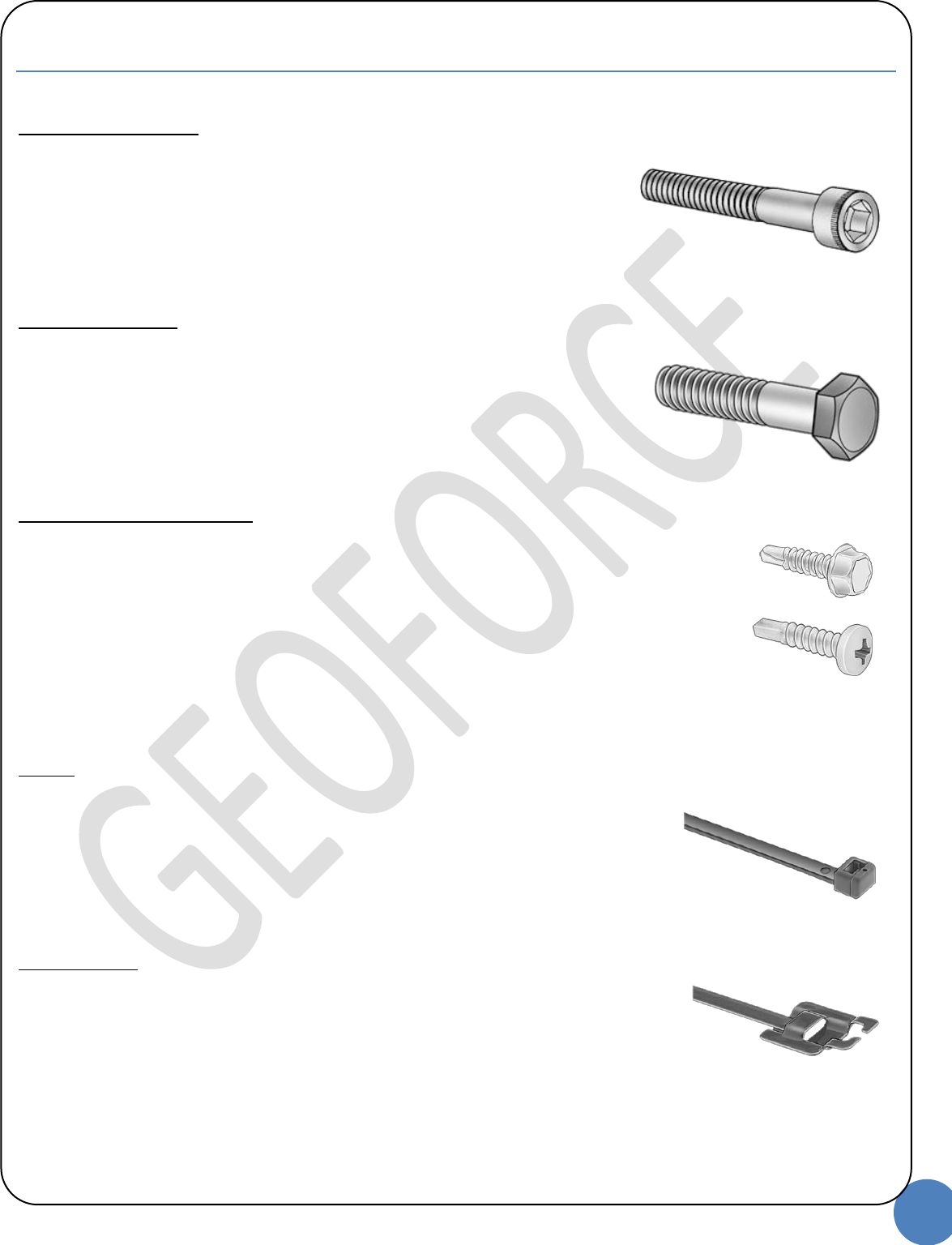
GT0 Mounting Hardware Examples
Utilizing the optional metal mounting bezel
Socket Head Cap Screws (Bolt length may vary depending on mounting surface)
Option 1 (standard):
Vendor: McMaster Carr (www.mcmaster.com)
Part Number: 92196A583
Description: 18-8 Stainless Steel Socket Head Cap Screw 5/16"-18 Thread, 1" Length
Option 2 (metric):
Vendor: McMaster Carr (www.mcmaster.com)
Part Number: 91292A148
Description: Metric 18-8 SS Socket Head Cap Screw M8 Thread, 25mm Length, 1.25mm Pitch
Hex Head Cap Screws (Bolt length may vary depending on mounting surface)
Option 1 (standard):
Vendor: McMaster Carr (www.mcmaster.com)
Part Number: 92240A583
Description: 18-8 SS Fully Threaded Hex Head Cap Screw 5/16"-18 Thread, 1" Length
Option 2 (metric):
Vendor: McMaster Carr (www.mcmaster.com)
Part Number: 91287A153
Description: Metric 18-8 SS Hex Head Cap Screw M8 Size, 25mm Length, 1.25mm Pitch, Fully Threaded
Self Drilling Sheet Metal Screws (Screw length may vary depending on mounting surface)
Option 1:
Vendor: McMaster Carr (www.mcmaster.com)
Part Number: 90420A650
Description: Corrosion-Resist Drilling Screw for Metal Hex Washer Head, 1/4"-20 Thread, 1" L, Drill Point #3
Option 2:
Vendor: McMaster Carr (www.mcmaster.com)
Part Number: 92364A278
Description: Pan Head Drilling Screw for Metal 410 SS, 1/4"-14 Thread, 1" Length, Drill Point #3
With and without the optional metal mounting bezel
Zip Ties (Length may vary depending on mounting surface)
Option 1:
Vendor: McMaster Carr (www.mcmaster.com)
Part Number: 70215K93
Description: Harsh-Environment Cable Tie Chemical-Resistent/Fire-Retardant Tefzel, 14-1/2" Length
Option 2:
Vendor: McMaster Carr (www.mcmaster.com)
Part Number: 6614K58
Description: Smooth Body Nylon Cable Tie 30" L, 9" Bundle Dia, 120# Tensile Strength, UV Resistant Black
Metal Strapping (Length may vary depending on mounting surface, requires a crimp tool)
Option 1:
Vendor: McMaster Carr (www.mcmaster.com)
Part Number: 69855K74
Description: Reusable SS Harsh-Environment Cable Tie Nylon-Coated, 18" Length, .25" Width
© Geoforce Inc., All Rights Reserved - version 130710a
6
GT0 User, Safety and Regulatory Guide | Geoforce Inc.
GT0 Maintenance
There is no user based maintenance for the GT0.
Notice: The lifespan of electronics can be affected by damage caused by electrostatic discharge.
Avoid direct contact with exposed electronic components such as battery contacts or electrical connections.
© Geoforce Inc., All Rights Reserved - version 130710a
7
GT0 User, Safety and Regulatory Guide | Geoforce Inc.
Appendix A: Shipping and Transport Guidance
Transport Codes
EXPORT CONTROL CLASSIFICATION NUMBER (ECCN)
5A991.b.3: Telecommunication equipment, not controlled by 5A001 “Telecommunications systems, equipment,
components and accessories”
US CENSUS BUREAU "SCHEDULE B" CODE
8526.91.0040: RADIO NAVIGATIONAL AID APPARATUS, N.E.S.O.I., NOT FOR USE IN CIVIL AIRCRAFT
INTERNATIONAL HARMONIZED TARIFF CODE (HTS)
8526.91.0040: RADIO NAVIGATIONAL AID APPARATUS, N.E.S.O.I., NOT FOR USE IN CIVIL AIRCRAFT
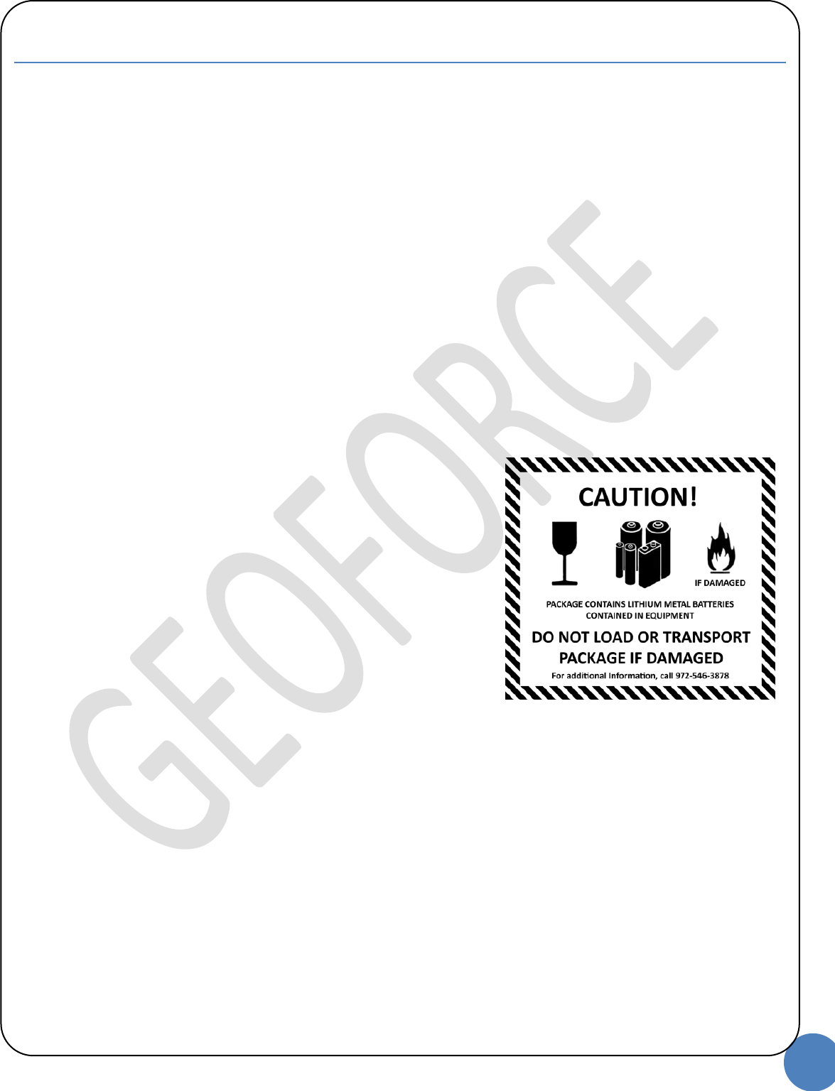
Lithium Battery Regulatory Information
Lithium Battery Cell Type: Lithium Metal Batteries Contained in Equipment
Cell Chemistry: Lithium-Thionyl-Chloride
Individual Cell Lithium Mass: 0.72 grams
Cell Installation Method: 4 individual cells in non-serviceable pack
IATA Regulated Packing Instruction: PI 970, Section 2
Battery manufacturer’s MSDS and UN38.3 Test report included in Appendix F.
© Geoforce Inc., All Rights Reserved - version 130710a
8
GT0 User, Safety and Regulatory Guide | Geoforce Inc.
Appendix B: Wireless/Environmental Regulatory Guidance
RF Radiation Exposure Statement
This equipment complies with FCC radiation exposure limits set forth for an uncontrolled environment. End users
must follow the specific operating instructions for satisfying RF exposure compliance. The antenna(s) used for this
transmitter must be installed to provide a separation distance of at least 20 cm from all persons and must not be
co-located or operating in conjunction with any other antenna or transmitter.
RF/Environmental Certifications
Certified to FCC and CE emissions, immunity, and safety regulations.
Meets FCC Part 25 regulations, Canada type approval, CISPR Publication 22 (1985 1st edition) & R&TTE Directive (1999/EC).
ROHS and WEEE compliant.
Regulatory Notices
FCC PART 15/25
Changes or modifications not expressly approved by the party responsible for compliance could void the user’s
authority to operate the equipment. The manufacturer is not responsible for any radio or TV interference caused by
un-authorized modifications to this equipment. Such modifications could void the user’s authority to operate the
equipment.
NOTE: This equipment has been tested and found to comply with the limits for a Class B digital device, pursuant to
part 15 of the FCC Rules. These limits are designed to provide reasonable protection against harmful interference in
a residential installation. This equipment generates uses and can radiate radio frequency energy and, if not in-
stalled and used in accordance with the instructions, may cause harmful interference to radio communications.
However, there is no guarantee that interference will not occur in a particular installation. If this equipment does
cause harmful interference to radio or television reception, which can be determined by turning the equipment off
and on, the user is encouraged to try to correct the interference by one or more of the following measures:
—Reorient or relocate the receiving antenna.
—Increase the separation between the equipment and receiver.
—Connect the equipment into an outlet on a circuit different from that to which the receiver is connected.
—Consult the dealer or an experienced radio/ TV technician for help.
NOTE: This device complies with part 15 of the FCC Rules. Operation is subject to the following two conditions: (1)
This device may not cause harmful interference, and (2) this device must accept any interference received,
including interference that may cause undesired operation.
This device complies with the requirements for radio astronomy site avoidance as specified by the Globalstar
National Science Foundation agreement of 2001. It is compliant with CFR 25.213.
This device automatically adjusts to transmission frequency according to its location and is compliant with
international regulatory requirements.
N23156
© Geoforce Inc., All Rights Reserved - version 130710a
9
GT0 User, Safety and Regulatory Guide | Geoforce Inc.
Regulatory Notices
ICES-003
Under Industry Canada regulations, this radio transmitter may only operate using an antenna of a type and
maximum (or lesser) gain approved for the transmitter by Industry Canada. To reduce potential radio interference
to other users, the antenna type and its gain should be so chosen that the equivalent isotropically radiated power
(EIRP) is not more than that necessary for successful communication.
Conformément à la réglementation d'Industrie Canada, le présent émetteur radio peut fonctionner avec une antenne
d'un type et d'un gain maximal (ou inférieur) approuvé pour l'émetteur par Industrie Canada. Dans le but de réduire les
risques de brouillage radioélectrique à l'intention des autres utilisateurs, il faut choisir le type d'antenne et son gain de
sorte que la puissance isotrope rayonnée équivalente (p.i.r.e.) ne dépasse pas l'intensité nécessaire à l'établissement
d'une communication satisfaisante.
This Class B digital apparatus complies with Canadian ICES-003.
Cet appareil numérique de la classe B est conforme à la norme NMB-003 du Canada.
This device complies with Industry Canada license-exempt RSS standard(s). Operation is subject to the following
two conditions: (1) this device may not cause interference, and (2) this device must accept any interference,
including interference that may cause undesired operation of the device.
Le présent appareil est conforme aux CNR d'Industrie Canada applicables aux appareils radio exempts de licence.
L'exploitation est autorisée aux deux conditions suivantes : (1) l'appareil ne doit pas produire de brouillage, et (2)
l'utilisateur de l'appareil doit accepter tout brouillage radioélectrique subi, même si le brouillage est susceptible d'en
compromettre le fonctionnement.
WEEE (2012/19/EU), ROHS (2002/95/EC)
The Geoforce GT0 is laser inscribed with the Restriction of Hazardous Substances (RoHS) Directive compliance
symbol. This signifies that all Geoforce GT0 units are RoHS compliant for restricted and hazardous substances.
The Geoforce GT0 is laser inscribed with the Waste Electrical and Electronic Equipment (WEEE) disposal symbol
and is classified in the WEEE Directive as Category 9 EEE: Monitoring and Control Instruments. This signifies that
all Geoforce GT0 units are classified as Electrical and Electronic Equipment (EEE) and should NOT be disposed of in
municipal waste areas. All local regulations must be followed in the disposal and disposition process of EEE.

© Geoforce Inc., All Rights Reserved - version 130710a
10
GT0 User, Safety and Regulatory Guide | Geoforce Inc.
Appendix C: Safety Regulatory Guidance
Hazloc Regulatory Notices
ANSI/UL913
CERTIFICATION PENDING
CSA22.2 NO. 157-92:2012
CERTIFICATION PENDING
Disposal Notices
WEEE
WARNING: DO NOT DISPOSE OF IN MUNICIPLE WASTE AREAS.
© Geoforce Inc., All Rights Reserved - version 130710a
11
GT0 User, Safety and Regulatory Guide | Geoforce Inc.
Appendix D: General Notices
Warranty Statement
Limited Hardware Warranty. Subject to the limitations set forth in the Geoforce Standard Service Agreement, Geoforce
warrants that for one (1) year from that date that Geoforce submits an invoice for such Hardware (the “Warranty Period”),
Hardware provided with the Service or purchased from Geoforce will be free of defects in materials and workmanship when
installed, operated, and serviced in strict accordance with Geoforce’s and the manufacturer’s requirements. If Hardware fails to
operate because of a defect in materials or workmanship within the Warranty Period, Geoforce will, at its sole option and at no
charge to Buyer, repair or replace it or arrange for its repair or replacement. Customer is responsible for removal and
replacement of failed hardware and shall return failed hardware to Geoforce within 30 days. THE WARRANTY SET FORTH ABOVE
FURTHERMORE DOES NOT COVER (A) HARDWARE THAT HAS BEEN TAMPERED WITH OR SERVICED WITHOUT SELLER’S
AUTHORIZATION; (B) HARDWARE THAT HAS BEEN LOST OR STOLEN; (C) HARDWARE THAT IS DESIGNED TO BE CONSUMABLE
OR NON-SERVICABLE SUCH AS BATTERIES; OR D) HARDWARE SUBJECTED TO ABUSE, MISUSE, NEGLECT OR HOSTILE
OPERATING ENVIRONMENTS.
Notices
Copyright by Geoforce Inc.
While this information is presented in good faith and believed to be accurate, Geoforce disclaims the implied warranties of
merchantability and fitness for a particular purpose and makes no express warranties except as may be stated in its written
agreement with and for its customers. In no event is Geoforce liable to anyone for any indirect, special or consequential
damages. The information and specifications in this document are subject to change without notice.

© Geoforce Inc., All Rights Reserved - version 130710a
12
GT0 User, Safety and Regulatory Guide | Geoforce Inc.
Appendix E: Supporting Documentation
GT0 Documentation
1) Battery Manufacturer’s MSDS
2) Battery UN38.3 Test Report