Geoforce MYTE Satellite Transmitter User Manual HW IS 0 0057 Revision 170905a

Geoforce Inc. Satellite Transmitter HW IS 0 0057 Revision 170905a

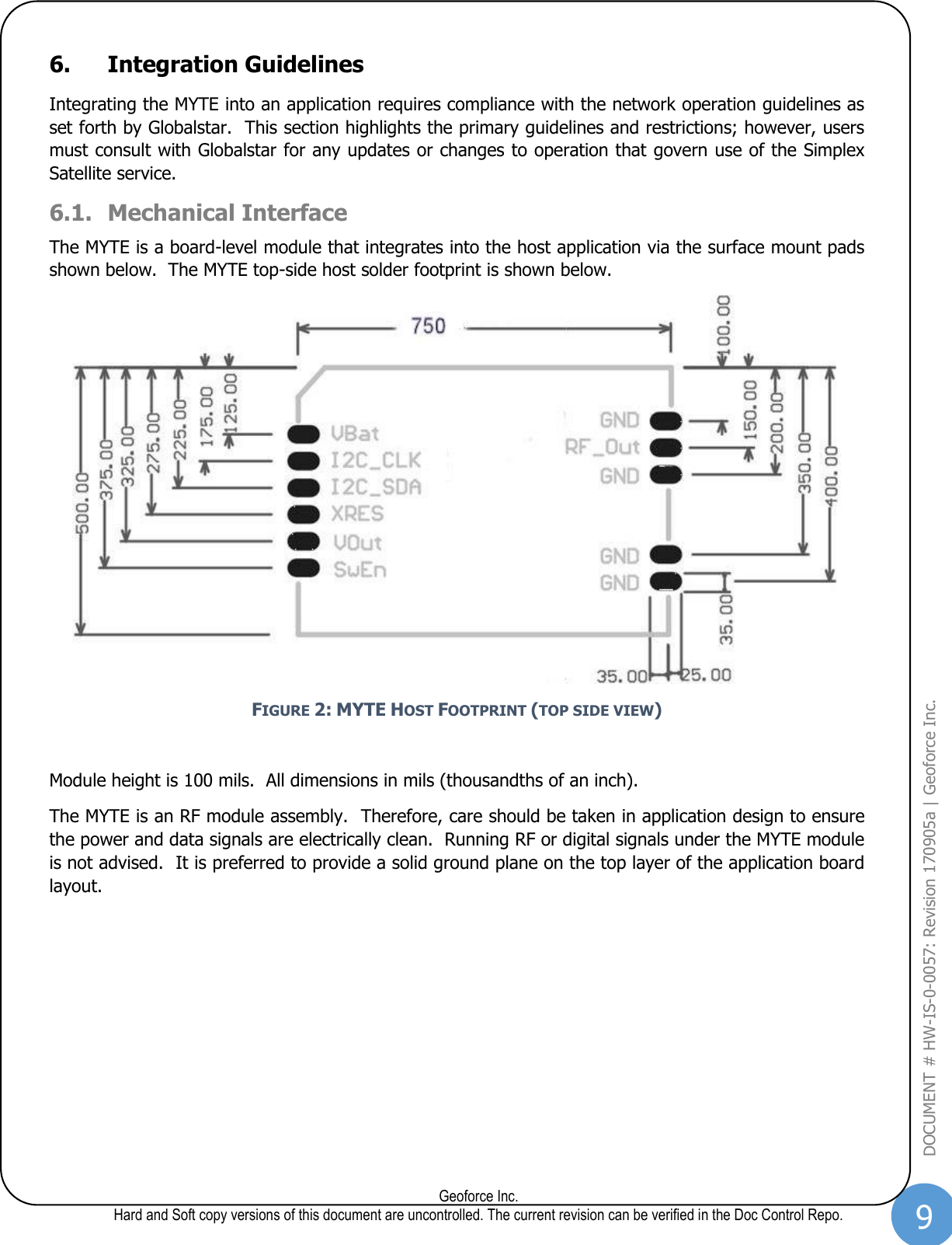
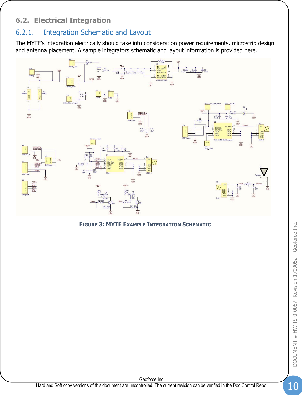
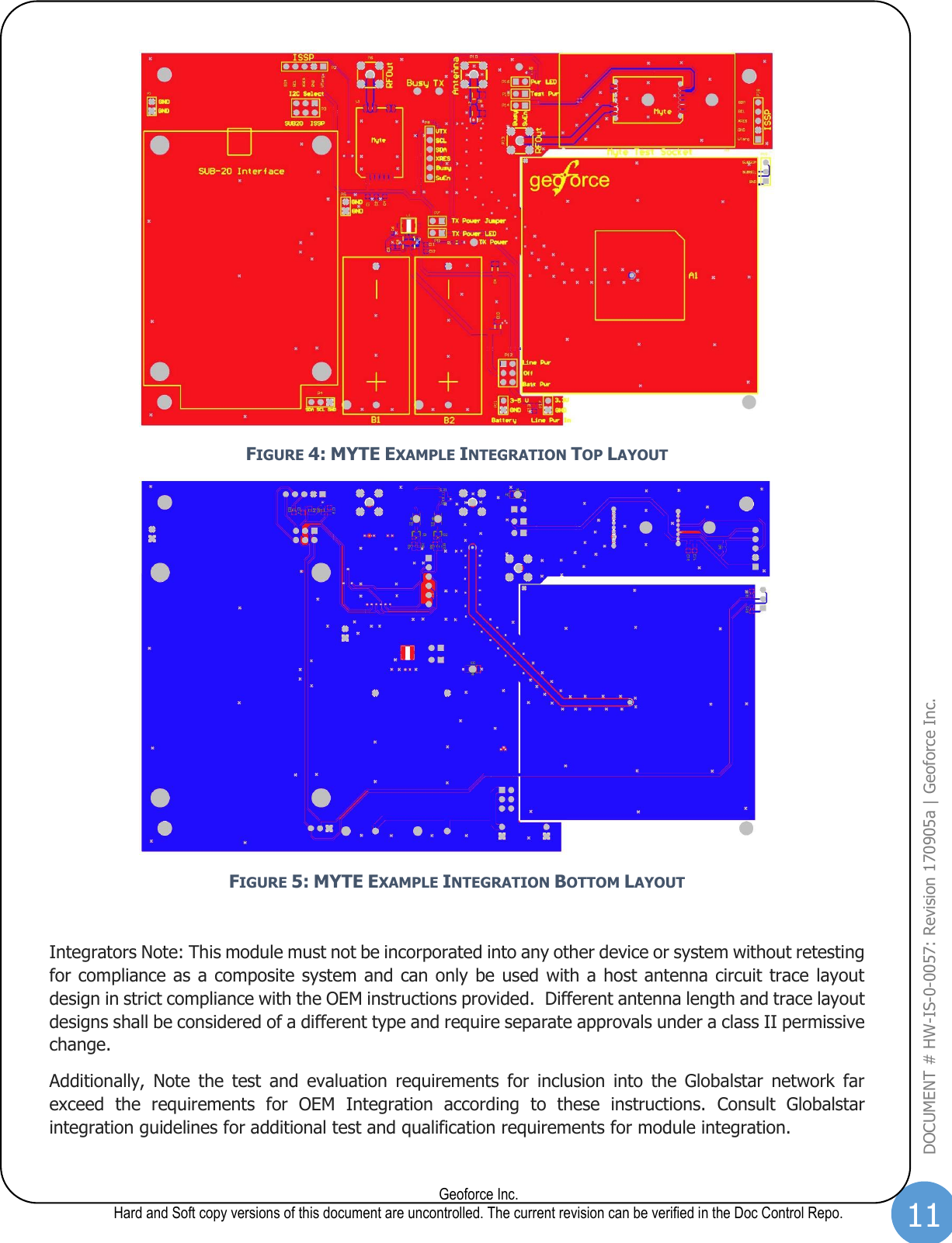
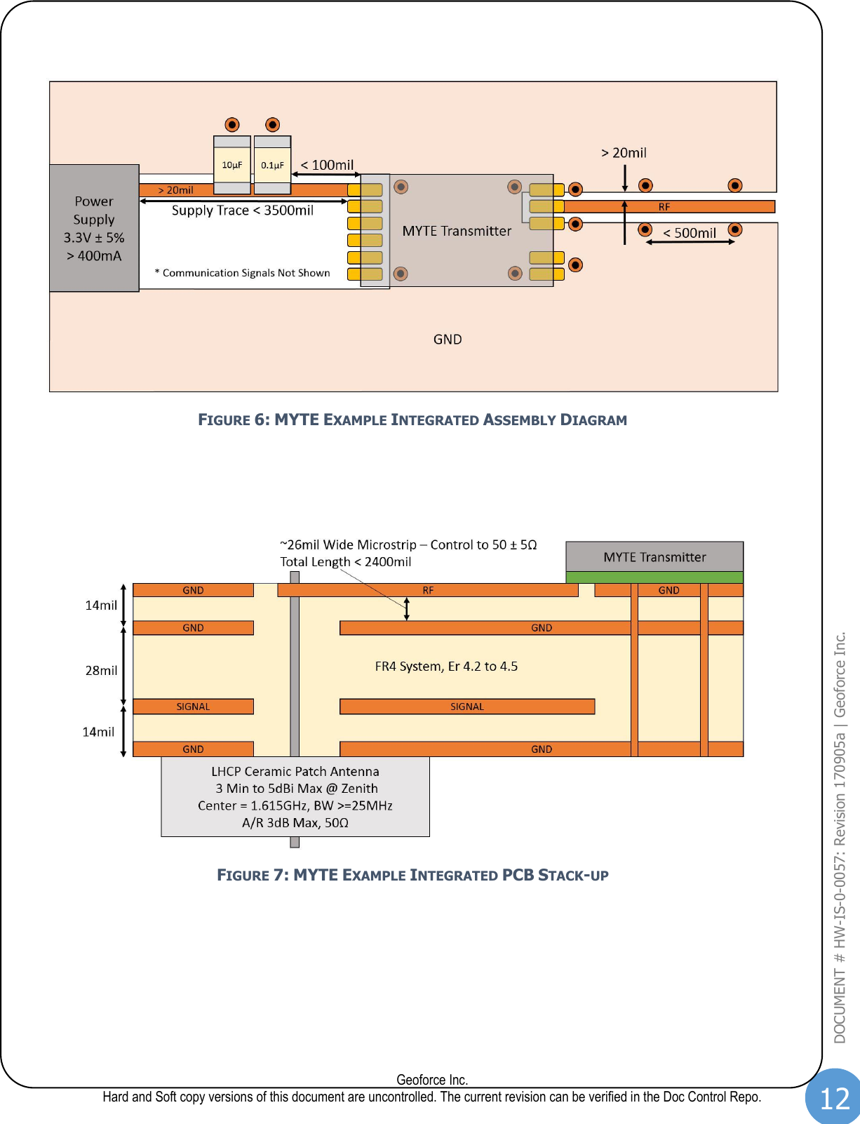
OEM Integrators Installation Guide

   MYTE Satellite Transmitter  Basic OEM/Integrators Installation Guide Document # HW-IS-0-0057 : Revision 170905a  FCCID: OWAMYTE IC ID: 10540A-MYTE Model Number: SCC-002        Author: Gary Naden CTO Signature: Gary Naden Date: 10/16/2017 Approval: Brandon Taylor Chief Hardware Architect Signature: Brandon Taylor Date: 10/16/2017
2  Geoforce Inc. Hard and Soft copy versions of this document are uncontrolled. The current revision can be verified in the Doc Control Repo. DOCUMENT # HW-IS-0-0057: Revision 170905a | Geoforce Inc.  Table of Contents SECTION  PAGE 1. DESCRIPTION/PURPOSE..................................................................................................................................................... 4 2. SCOPE .................................................................................................................................................................................. 4 3. DEFINITIONS AND REFERENCES ......................................................................................................................................... 5 3.1. DEFINITIONS AND ABBREVIATIONS ................................................................................................................................................ 5 4. MYTE DEVICE OVERVIEW .................................................................................................................................................... 6 4.1. SATELLITE MESSAGING METHOD ................................................................................................................................................... 6 5. ON-AIR INTERFACE ............................................................................................................................................................. 7 5.1. RF MODULATION ....................................................................................................................................................................... 7 5.2. EMI/EMC CONFORMANCE ........................................................................................................................................................... 8 6. INTEGRATION GUIDELINES ................................................................................................................................................ 9 6.1. MECHANICAL INTERFACE ............................................................................................................................................................. 9 6.2. ELECTRICAL INTEGRATION ......................................................................................................................................................... 10 6.2.1. Integration Schematic and Layout .................................................................................................................................... 10 6.2.2. Power Supply .................................................................................................................................................................. 13 6.2.3. RF Interface .................................................................................................................................................................... 13 6.2.4. Antenna Guidelines .......................................................................................................................................................... 13 6.2.5. Composite System Compliance Testing ............................................................................................................................. 13 6.2.6. Composite System Integration Test .................................................................................................................................. 14 6.2.7. Composite System Production Test ................................................................................................................................... 14 6.3. REGULATORY CERTIFICATIONS AND MYTE LABELING ....................................................................................................................... 15 6.3.1. MYTE Device Labeling ...................................................................................................................................................... 15 6.3.2. MYTE Serialization and ESN Coding .................................................................................................................................. 15 6.3.3. Integrated Product Labelling and FCC Regulatory Markings ................................................................................................ 16 6.3.4. Industry Canada Guidelines .............................................................................................................................................. 17 6.4. GLOBALSTAR CERTIFICATIONS .................................................................................................................................................... 18 7. REVISION HISTORY .......................................................................................................................................................... 19
3  Geoforce Inc. Hard and Soft copy versions of this document are uncontrolled. The current revision can be verified in the Doc Control Repo. DOCUMENT # HW-IS-0-0057: Revision 170905a | Geoforce Inc.  List of Figures SECTION  PAGE FIGURE 1: MYTE APPROXIMATE SIZE ...................................................................................................................... 6 FIGURE 2: MYTE HOST FOOTPRINT (TOP SIDE VIEW).................................................................................................. 9 FIGURE 3: MYTE EXAMPLE INTEGRATION SCHEMATIC ............................................................................................... 10 FIGURE 4: MYTE EXAMPLE INTEGRATION TOP LAYOUT .............................................................................................. 11 FIGURE 5: MYTE EXAMPLE INTEGRATION BOTTOM LAYOUT ........................................................................................ 11 FIGURE 6: MYTE EXAMPLE INTEGRATED ASSEMBLY DIAGRAM ...................................................................................... 12 FIGURE 7: MYTE EXAMPLE INTEGRATED PCB STACK-UP ............................................................................................ 12 FIGURE 8: MYTE LABEL ..................................................................................................................................... 15 List of Tables SECTION  PAGE TABLE 1: RF CHANNELS IMPLEMENTED .................................................................................................................... 7 TABLE 2: FCC PART 15.109 SUMMARY ................................................................................................................... 8 TABLE 3: PART 25.202 SUMMARY .......................................................................................................................... 8 TABLE 4: EN 301-441 SUMMARY........................................................................................................................... 8
4  Geoforce Inc. Hard and Soft copy versions of this document are uncontrolled. The current revision can be verified in the Doc Control Repo. DOCUMENT # HW-IS-0-0057: Revision 170905a | Geoforce Inc.  1. Description/Purpose The MYTE (SCC-002) device is a radio transmitter module that creates the radio frequency (RF) signals to relay small packets of data to the Globalstar Simplex Data Service satellite network.  The MYTE serves as a communication gateway in an embedded application to send transmit-only (simplex) data.  Data packets are in small, 9-byte segments.  The MYTE supports 9, 18, 27 or 36-byte data payloads. The Globalstar Simplex Data Service comprises a set of low-earth-orbit (LEO) satellites operating as bent-pipe data relay devices to ground earth data collection points.  This specification stipulates the operational and physical requirements for the MYTE transmitter device that is compatible with this satellite network system. The  MYTE  device  is  the  radio  transmitter  only  and  its  integration  must  follow  the  follow  basic guidelines/limitations. 1. The MYTE must be fully integrated into a larger OEM installation/application device to provide utility. 2. The  OEM  integrator  is  responsible  for  ensuring  that  the  end-user  has  no  manual  instructions  to remove or install module. 3. The module is limited to installation in mobile or fixed applications. This  specification  provides  the  physical,  electrical  and  integration  requirements  to  enable  application development. The  purpose  of  this  document  is  to  provide  some  notes  on  basic  device  integration  for  the  MYTE transmitter module. 2. Scope This User/Integrators Guide applies only to the Geoforce MYTE transmitter.
5  Geoforce Inc. Hard and Soft copy versions of this document are uncontrolled. The current revision can be verified in the Doc Control Repo. DOCUMENT # HW-IS-0-0057: Revision 170905a | Geoforce Inc.  3. Definitions and References 3.1. Definitions and Abbreviations The following definitions used herein shall have the meanings as defined below: a) BPSK: Binary Phase Shift Keyed modulation.  This is the data modulation incorporated by the MYTE compliant with the Globalstar Simplex Data Service. b) EIRP: Effective Isotropic Radiated Power. c) EMI: Electro Magnetic Interference. d) ESN: Electronic Serial Number.  Unique serialization number for each transmitter. e) EVM: Error Vector Magnitude:  A measure of BPSK modulation quality. f) DSSS: Direct Sequence Spread Spectrum.  This is the spreading method coupled with BPSK g) Globalstar: The term “Globalstar” means Globalstar, Inc., a Delaware USA Corporation having offices at 461 South Milpitas Blvd, Milpitas, California 95035 h) Globalstar  Simplex  Data  Service:  The  term  “Globalstar  Simplex  Data  Service”  refers  to communications from simplex transmitters relayed over Globalstar’s network of low earth orbit satellites to Globalstar gateways for distribution to end customers. i) GPS: The term GPS is an acronym meaning global positioning system. j) LEO: The term LEO is an acronym meaning low earth orbit. k) PRS: Pseudo Random Sequence.  The digital method for creating the DSSS spreading code. l) RAS: Radio Astronomy Service.  Regions of restricted frequency use compliant with the Globalstar radio spectrum license. m) RF:  Radio Frequency n) RTU: Remote Telemetry Unit, generically used as the device that contains the MYTE integrated into it as the satellite communication means. o) TCXO: Temperature Compensated Crystal Oscillator.
6  Geoforce Inc. Hard and Soft copy versions of this document are uncontrolled. The current revision can be verified in the Doc Control Repo. DOCUMENT # HW-IS-0-0057: Revision 170905a | Geoforce Inc.  4. MYTE Device Overview The MYTE device is a radio transmitter module that contains the functionality to accept configuration and data from a host application and convey data to the Globalstar Simplex Data Service satellite system.  FIGURE 1: MYTE APPROXIMATE SIZE 4.1. Satellite Messaging Method The MYTE device manages all the required messaging to be compliant to the Globalstar Simplex Data Service.  The application interface need only configure the device once and send data to the MYTE using the I2C serial interface.  The MYTE will queue the data to be sent and manage the process of transmitting the data to the satellite system. Because the messages are transmitted unsolicited and without the benefit of a two-way data link with the satellite system, each message is transmitted several times with a random delay component between  transmits  of  roughly  7±2  minutes.  Recommended  configuration  setting  transmits  each message  three  times  with  time  delays  between  each  transmission  to  allow  for  the  satellite constellation to shift in position.  The configuration parameters of the MYTE allow for adjustment of number of transmissions and time delays between transmissions. This overview is provided to briefly demonstrate  how  the  MYTE  functions  in  order  for  application  developers  to  understand  how  the simplex  system  operates.    Integrators  should  know  that  sending  a  message  for  transmit  may therefore take up to 20 minutes to complete the transmit sequence.  This does not mean that system latency  is  typically  that  long,  but  because  the  MYTE  has  no  way  to  discern  if  the  message  was successful  on  first  or  subsequent  attempts,  it  will  repeat  the  message transmit  per  configuration setting.    The  satellite  system  will  deliver  the  first  received  message  captured,  typically  the  first message and thus the probabilistic system latency is seconds, not minutes.  Nevertheless, on rare occasions the system may miss the first message and the data packet will have a new chance for packet delivery success on subsequent trials.
7  Geoforce Inc. Hard and Soft copy versions of this document are uncontrolled. The current revision can be verified in the Doc Control Repo. DOCUMENT # HW-IS-0-0057: Revision 170905a | Geoforce Inc.  5. On-Air Interface The MYTE transmits data in a radio format compatible with the Globalstar Simplex Data Service.  This section provides a brief overview of the operation of the network service. Greater detail can be found in the requirements definitions set forth by Globalstar. 5.1. RF Modulation  The MYTE transmits data using Direct Sequence Spread Spectrum (DSSS) carrier with a Binary Phase Shift Keyed (BPSK) data modulation.  The MYTE can be configured to send data on one of four radio center  frequencies.    Globalstar  operational  requirements  for  channel  usage  must  be  observed  by application developers.  Generally, channel A is used for North American operations except where the device is in proximity of Radio Astronomy Sites (RAS), where channel C is prescribed.  Use in other global regions uses channel C.  The channels are specified as: RF Channel Channel A = 1611.25 MHz center frequency Channel B = 1613.75 MHz center frequency Channel C = 1616.25 MHz center frequency Channel D = 1618.75 MHz center frequency TABLE 1: RF CHANNELS IMPLEMENTED Nominal Transmit output power shall be 18 dBm ± 2 dB RMS overall operating conditions.
8  Geoforce Inc. Hard and Soft copy versions of this document are uncontrolled. The current revision can be verified in the Doc Control Repo. DOCUMENT # HW-IS-0-0057: Revision 170905a | Geoforce Inc.  5.2. EMI/EMC Conformance The MYTE shall carry an FCC Part 25 modular device certification, stipulating a maximum antenna gain of +5 dBi.  In addition, the MYTE shall be verified compliant to FCC Part 15 and EN 301-441 for EU use. FCC Part 15.109 Absolute Frequency Offset from Carrier EIRP Measurement Bandwidth / Method 30 to 88 - 90 V/m 10 meters 88-216 - 150 V/m 10 meters 216-960 - 210 V/m 10 meters Above 960 - 300 V/m 10 meters TABLE 2: FCC PART 15.109 SUMMARY Part 25.202 Absolute Frequency Offset from Carrier EIRP Measurement Bandwidth / Method Frequency Offset (Authorized bandwidth 2.5 MHz) Below –6.25 MHz -35 dBc 4 KHz Average -6.25 to –1.25 MHz -35 dBc 4 KHz Average -2.5 to –1.25 MHz -25 dBc 4 KHz Average Frequency Offset (Authorized Bandwidth 2.5 MHz) 1.25 to 2.5 MHz -25 dBc 4 KHz Average 2.5 to 6.25 MHz -35 dBc 4 KHz Average Above 6.25 MHz -35 dBc (Assuming 18dBm output power) 4 KHz Average TABLE 3: PART 25.202 SUMMARY EN 301-441 Absolute Frequency Offset from Carrier EIRP Measurement Bandwidth / Method 0.1 to 30  -36 dBm 10 KHz Peak-Hold 30 to 1000  -36 dBm 100 KHz Peak-Hold 1000 to 1559  -30 dBm 1 MHz Average 1559 to 1580.42  -40 dBm 1 MHz Average 1580.42 to 1605  -40 dBm 1 MHz Average 1605 to 1610  -40 dBm to 20 dBm 1 1 MHz Average Frequency Offset (Does not apply below 1610 MHz) -17.75 to –3.05 MHz -26 dBm 30 KHz Average -3.05 to –2.165 MHz -26 dBm to -23 dBm 1 30 KHz Average -2.615 to –1.9 MHz -15 dBm 30 KHz Average -1.9 to –1.475 MHz -15 dBm to -8.5 dBm 1 30 KHz Average -1.475 to –1.41 MHz -8.5 dBm to -5 dBm 1 30 KHz Average -1.41 to –1.25 MHz -5 dBm 30 KHz Average Frequency Offset (Does not apply above 1628.5 MHz) 1.25 to 1.41 MHz -5 dBm 30 KHz Average 1.41 to 1.475 MHz -5 dBm to -8.5 dBm 1 30 KHz Average 1.475 to 1.9 MHz -8.5 dBm to -15 dBm 1 30 KHz Average 1.9 to 2.615 MHz -15 dBm 30 KHz Average 2.165 to 3.05 MHz -23 dBm to -26 dBm 1 30 KHz Average 3.05 to 17.75 MHz -26 dBm 30 KHz Average 1628.5 to 1631.5  -30 dBm 30 KHz Average 1631.5 to 1636.5  -30 dBm 100 KHz Average 1636.5 to 1646.5  -30 dBm 300 KHz Average 1646.5 to 1666.5  -30 dBm 1 MHz Average 1666.5 to 2200  -30 dBm 3 MHz Average 2200 to 12,750  -30 dBm 3 MHz Peak Hold TABLE 4: EN 301-441 SUMMARY                                            1 Limit in dB varies linearly
9  Geoforce Inc. Hard and Soft copy versions of this document are uncontrolled. The current revision can be verified in the Doc Control Repo. DOCUMENT # HW-IS-0-0057: Revision 170905a | Geoforce Inc.  6. Integration Guidelines Integrating the MYTE into an application requires compliance with the network operation guidelines as set forth by Globalstar.  This section highlights the primary guidelines and restrictions; however, users must consult with Globalstar for any updates or changes to operation that govern use of the Simplex Satellite service. 6.1. Mechanical Interface The MYTE is a board-level module that integrates into the host application via the surface mount pads shown below.  The MYTE top-side host solder footprint is shown below.    FIGURE 2: MYTE HOST FOOTPRINT (TOP SIDE VIEW)  Module height is 100 mils.  All dimensions in mils (thousandths of an inch). The MYTE is an RF module assembly.  Therefore, care should be taken in application design to ensure the power and data signals are electrically clean.  Running RF or digital signals under the MYTE module is not advised.  It is preferred to provide a solid ground plane on the top layer of the application board layout.
10  Geoforce Inc. Hard and Soft copy versions of this document are uncontrolled. The current revision can be verified in the Doc Control Repo. DOCUMENT # HW-IS-0-0057: Revision 170905a | Geoforce Inc.  6.2. Electrical Integration 6.2.1. Integration Schematic and Layout The MYTE’s integration electrically should take into consideration power requirements, microstrip design and antenna placement. A sample integrators schematic and layout information is provided here.  FIGURE 3: MYTE EXAMPLE INTEGRATION SCHEMATIC
11  Geoforce Inc. Hard and Soft copy versions of this document are uncontrolled. The current revision can be verified in the Doc Control Repo. DOCUMENT # HW-IS-0-0057: Revision 170905a | Geoforce Inc.   FIGURE 4: MYTE EXAMPLE INTEGRATION TOP LAYOUT  FIGURE 5: MYTE EXAMPLE INTEGRATION BOTTOM LAYOUT  Integrators Note: This module must not be incorporated into any other device or system without retesting for compliance as a composite system and can only be used with a host antenna circuit trace layout design in strict compliance with the OEM instructions provided.  Different antenna length and trace layout designs shall be considered of a different type and require separate approvals under a class II permissive change. Additionally,  Note  the  test  and  evaluation  requirements  for  inclusion  into  the  Globalstar  network  far exceed  the  requirements  for  OEM  Integration  according  to  these  instructions.  Consult  Globalstar integration guidelines for additional test and qualification requirements for module integration.
12  Geoforce Inc. Hard and Soft copy versions of this document are uncontrolled. The current revision can be verified in the Doc Control Repo. DOCUMENT # HW-IS-0-0057: Revision 170905a | Geoforce Inc.    FIGURE 6: MYTE EXAMPLE INTEGRATED ASSEMBLY DIAGRAM     FIGURE 7: MYTE EXAMPLE INTEGRATED PCB STACK-UP
13  Geoforce Inc. Hard and Soft copy versions of this document are uncontrolled. The current revision can be verified in the Doc Control Repo. DOCUMENT # HW-IS-0-0057: Revision 170905a | Geoforce Inc.  6.2.2. Power Supply The module is to be powered at 3.3V ±5%, including transients induced by changes in current draw.  The module power supply must be decoupled with 0.1µF and 10µF low ESR ceramic capacitors as close to  the  power  supply connection as  possible  but no further than 100mil.    The  power  supply  must be capable of delivering pulse current in excess of 400mA.  The power supply connection trace should be kept as  short as possible and shall be of at least 20mil width, no longer  than 3500mil, and shall not exceed 0.1Ohm. 6.2.3. RF Interface In order  to  guarantee compliance with FCC Part  25  Modular Transmitter requirements and avoid the possibility of generating unintentional emissions, the interface between the transmitter module and an approved antenna must strictly adhere to the following design requirements.  The RF connection on the host board must be connected to an approved antenna via a microstrip or stripline transmission line.  The impedance of this trace must be controlled to 50±5Ohm and its length shall not exceed 2400mil.  The transmission line layer should be surrounded by a ground plane spaced at least 20mil from the edges of  the  trace.    Stitching vias  between the  transmission line  layer  ground plane  and  the  ground plane counterpoise(s) shall be placed at least every 500mil along the length of the trace.  No signal traces are to pass below the transmitter module or transmission line on adjacent (counterpoise) layer(s) or within 20mil  of  any  transmission  line  vias or  antenna  feed  pin  on any  layer.    A  ground  plane  with multiple stitching vias should be placed under the extents of the module. 6.2.4. Antenna Guidelines The MYTE may be integrated with an antenna with a maximum directivity gain of +5dBi or less, such as the  Spectrum  Advanced  Specialties  Products  antenna  part  number  PA25-1615-025SA  or  PA451615-1575SA (dual band sat+gps) or Tallysman Wireless part numbers TW2515 or TW11-0006-X. No  external  amplifiers,  trace  antennas,  or  antennas  other  than  those  which  meet  the  following requirements are permitted under the terms of the modular approval: • Antenna Type:  Left-Hand Circularly Polarized Ceramic Patch • Nominal Impedance:  50Ohm • Antenna Gain:  3dBi Minimum to 5dBi Maximum at Zenith • Nominal Center Frequency:  1.615GHz • Bandwidth:  >= 25MHz • Axial Ratio:  3dB Maximum at Zenith Special attention must  be  given to  antenna  performance as  specified in  Globalstar  document  GS-07-1247. 6.2.5. Composite System Compliance Testing The integrator of a module of this type shall be responsible for ensuring compliance for unintentional emissions per FCC Part 15.107 and 15.109 and RSS-170 on the composite system as a whole. Failure to perform these tests may result in non-compliance with FCC and IC emissions limits.
14  Geoforce Inc. Hard and Soft copy versions of this document are uncontrolled. The current revision can be verified in the Doc Control Repo. DOCUMENT # HW-IS-0-0057: Revision 170905a | Geoforce Inc.  6.2.6. Composite System Integration Test The integrated product design shall be evaluated for compliance by removing the patch antenna and connecting an un-terminated end of a coaxial cable of known cable loss at 1.6GHz to the antenna feed point.  The other end of the coaxial cable will be connected to a spectrum analyzer capable of measuring a +25dBm signal at 1.6GHz with 100kHz and 3MHz bandwidths.   The  spectrum  analyzer  shall  be  configured  for  a  center  frequency  of  1.61125GHz,  span  of  10MHz, reference level of +25dBm, average detector, range of 100dB, resolution and video bandwidths of 3MHz, sweep  time  of  <100msec,  and  trace  configured  for  maximum  hold.    The  application  processor  shall command the MYTE transmitter to transmit a 9-byte packet on Channel A via the I2C interface.  The power  measured  by  the  spectrum  analyzer  at  the  center  frequency  shall  be  between  +18dBm  and +20dBm minus the known cabling losses.   The spectrum analyzer resolution and video bandwidths shall be then set to 100kHz, the maximum trace hold  reset.    The  application  processor  on  the  host  board  will  then  instruct  the  MYTE  transmitter  to transmit another 9-byte packet on Channel A via the I2C interface.  The primary band average power shall  be  averaged  from  1.610625GHz  to  1.611875GHz  and  the  sideband  powers  averaged  from 1.609188GHz to 1.609812GHz and from 1.612688GHz to 1.613312GHz.  Both averaged sideband powers shall be at least 20dB lower than the average primary band power. 6.2.7. Composite System Production Test Production testing of end products incorporating the MYTE transmitter module shall be verified to comply with  relevant  emissions  standards  by  measurement  of  the  radiated  spectrum  over  the  duration of  a transmit event.  A spectrum analyzer capable of measuring a 1.61125GHz signal with 100kHz bandwidth shall be connected to a receiving antenna through a low-loss coaxial cable.  The receiving antenna shall be nominal 50Ohm LHCP ceramic patch type with center frequency of 1615MHz±10MHZ, 1dB BW >= 25MHz, A/R 3dB Max, Gain of 3dBi min to 5dBi max at zenith.  The antenna shall be positioned about 200cm above the production device under test such that the zenith of both transmit and receive antennas are pointed directly at one another. The spectrum analyzer shall be configured for a center frequency of 1.61125GHz, span of 10MHz, average detector, reference level of +10dBm, range of 100dB, resolution and video bandwidths of 100kHz, sweep time of <100msec, and trace configured for maximum hold.  The application processor shall command the MYTE transmitter to transmit a 9-byte packet on Channel A via the I2C interface.  The primary band average power shall be averaged from 1.610625GHz to 1.611875GHz and the sideband powers averaged from 1.609188GHz to 1.609812GHz and from 1.612688GHz to 1.613312GHz.  Both averaged sideband powers shall be at least 20dB lower than the average primary band power.
15  Geoforce Inc. Hard and Soft copy versions of this document are uncontrolled. The current revision can be verified in the Doc Control Repo. DOCUMENT # HW-IS-0-0057: Revision 170905a | Geoforce Inc.  6.3. Regulatory Certifications and MYTE Labeling The application that incorporates the MYTE device must be properly certified for the region of operation.  MYTE will carry modular certifications for FCC, IC.  In addition, the MYTE has completed EN 301-441 radio testing for potential use in the EU.  These test results may be obtained from Geoforce, Inc.  The integrator however must secure operational certifications and testing of the final integrated product in compliance with regional regulatory restrictions including the required marking of the end device.   Modular Certification Restrictions: • The MYTE is authorized only for mobile devices. Installation in portable devices is not permissible. • The MYTE must be installed in such a way as to prevent approach within 20 cm of the transmitting antenna. Integrators must ensure that the product user’s manual includes the standard 20 cm warning to end users. • The MYTE may not be collocated with any other transmitter. 6.3.1. MYTE Device Labeling The MYTE device (Model SCC-002) is  marked with the FCC ID and IC  certification number as  shown below.    FIGURE 8: MYTE LABEL Actual size of the label is 0.500” x 0.4375” 6.3.2. MYTE Serialization and ESN Coding Each MYTE transmitter label will also contain a Micro-QR barcode and human readable Electronic Serial Number (ESN).  The left-most digit in the labeled ESN is the manufacture ID, so as shown above, the ESN is 2-3000000.  The ESN notation is decimal, with the Manufacture ID weighted as 2^23.  The formula below provides the conversion for the ESN labeling to hexadecimal notation used in ESN reads from the MYTE. ESNhex = (MFG_ID * 2^23) + ESNdec For the example label above: ESNhex = 0x012DC6C0 = (2 * 2^23) + 3000000
16  Geoforce Inc. Hard and Soft copy versions of this document are uncontrolled. The current revision can be verified in the Doc Control Repo. DOCUMENT # HW-IS-0-0057: Revision 170905a | Geoforce Inc.  6.3.3. Integrated Product Labelling and FCC Regulatory Markings When  the  MYTE  is  incorporated  into  a  product,  the  product  must  be  appropriately  labeled.    The application designer must ensure the product labeling is accurate and complete.  At a minimum, it must contain a statement or marking to designate the device contains the radio transmitter. “Contains Transmitter Module FCC ID: OWAMYTE” or “Contains FCCID: OWAMYTE” Consult the regulatory requirements for product marking for the latest requirements for each region or application for the application product to ensure compliance.    Note Conspicuously: This equipment has been tested and found to comply with the limits for a Class B device, pursuant to part 15 of the FCC Rules. These limits are designed to provide reasonable protection  against  harmful  interference  in  a  residential  installation.  This  equipment generates, uses and can radiate radio frequency energy and, if not installed and used in accordance  with  the  instructions,  may  cause  harmful  interference  to  radio communications. However,  there  is  no  guarantee  that  interference  will  not  occur  in  a  particular installation.  If  this  equipment  does  cause  harmful  interference  to  radio  or  television reception, which  can  be  determined  by  turning the  equipment  off  and  on,  the  user  is encouraged to try to correct the interference by one or more of the following measures: —Reorient or relocate the receiving antenna. —Increase the separation between the equipment and receiver. —Connect  the  equipment  into  an  outlet  on  a  circuit  different  from  that  to  which  the receiver is connected. —Consult the dealer or an experienced radio/TV technician for help. Caution:  Changes or modifications not expressly approved by the party responsible for compliance could void the user's authority to operate the equipment Note Conspicuously: NOTICE: This equipment complies with the FCC RF Exposure Limits. A minimum of 20 centimeters (8 inches) separation between the device and the user and all other persons should be maintained. Note Conspicuously: WARNING: Changes or modifications not expressly approved by Geoforce may render the device non-compliant to FCC and other regulatory body standards for operation and may void the user’s authority to operate the equipment.
17  Geoforce Inc. Hard and Soft copy versions of this document are uncontrolled. The current revision can be verified in the Doc Control Repo. DOCUMENT # HW-IS-0-0057: Revision 170905a | Geoforce Inc.  6.3.4. Industry Canada Guidelines  If the MYTE is to be integrated into a device to be used in Canada, the required notices are specified in the RSS documents (including RSS-Gen) applicable to the equipment model. These notices are required to be shown in a conspicuous location in the user manual for the equipment, or to be displayed on the equipment model. If more than one notice is required, the equipment model(s) to which each notice pertains should be identified. Suppliers of radio apparatus shall provide notices and user information in both English and French. Under Industry Canada regulations, this radio transmitter may only operate  using  an  antenna  of  a  type  and  maximum  (or  lesser)  gain approved  for  the  transmitter  by  Industry  Canada.  To  reduce potential radio interference to other users, the antenna type and its  gain  should  be  so  chosen  that  the  equivalent  isotropically radiated  power  (EIRP)  is  not  more  than  that  necessary  for successful communication.   Conformément  à  la  réglementation  d'Industrie  Canada,  le  présent émetteur radio peut fonctionner avec une antenne d'un type et d'un gain maximal (ou inférieur) approuvé pour l'émetteur par Industrie Canada.  Dans  le  but  de  réduire  les  risques  de  brouillage radioélectrique  à  l'intention  des  autres  utilisateurs,  il  faut choisir  le  type  d'antenne  et  son  gain  de  sorte  que  la  puissance isotrope rayonnée équivalente (p.i.r.e.) ne dépasse pas l'intensité nécessaire à l'établissement d'une communication satisfaisante. The above notice may be affixed to the device instead of displayed in the user manual. User manuals for transmitters equipped with detachable antennas shall also contain the following notice in a conspicuous location:   This  radio  transmitter  (identify  the  device  by  certification number,  or  model  number  if  Category  II)  has  been  approved  by Industry Canada to operate with the antenna types listed below with the  maximum  permissible  gain  and  required  antenna  impedance  for each  antenna  type  indicated.  Antenna  types  not  included  in  this list,  having  a  gain  greater  than  the  maximum  gain  indicated  for that type, are strictly prohibited for use with this device.  Le présent émetteur radio (identifier le dispositif par son numéro de  certification  ou  son  numéro  de  modèle  s'il  fait  partie  du matériel de catégorie I) a été approuvé par Industrie Canada pour fonctionner avec les types d'antenne énumérés ci-dessous et ayant un gain admissible maximal et l'impédance requise pour chaque type d'antenne. Les types d'antenne non inclus dans cette liste, ou dont le  gain  est  supérieur  au  gain  maximal  indiqué,  sont  strictement interdits pour l'exploitation de l'émetteur.
18  Geoforce Inc. Hard and Soft copy versions of this document are uncontrolled. The current revision can be verified in the Doc Control Repo. DOCUMENT # HW-IS-0-0057: Revision 170905a | Geoforce Inc.  User manuals for license-exempt radio apparatus shall contain the following or equivalent notice in a conspicuous location in the user manual or alternatively on the device or both.  This  device  complies  with  Industry  Canada  license-exempt  RSS standard(s). Operation is subject to the following two conditions: (1)  this  device  may  not  cause  interference,  and  (2)  this  device must accept any interference, including interference that may cause undesired operation of the device. Le  présent  appareil  est  conforme  aux  CNR  d'Industrie  Canada applicables aux appareils radio exempts de licence. L'exploitation est  autorisée  aux  deux  conditions  suivantes  :  (1)  l'appareil  ne doit pas produire de brouillage, et (2) l'utilisateur de l'appareil doit  accepter  tout  brouillage  radioélectrique  subi,  même  si  le brouillage est susceptible d'en compromettre le fonctionnement 6.4. Globalstar Certifications  The  application  that  incorporates the  MYTE  device  must  be  properly  approved  for  use  by  Globalstar before use over their network.  This will include proper channelization for regional use and other radio telemetry requirements. Contact Globalstar for RTU certification procedures.  Special attention must be given to channelization of use as specified in Globalstar document GS-07-1248.
19  Geoforce Inc. Hard and Soft copy versions of this document are uncontrolled. The current revision can be verified in the Doc Control Repo. DOCUMENT # HW-IS-0-0057: Revision 170905a | Geoforce Inc.  7. Revision History Rev Description Approval Date 170905a Initial Release  B. Taylor 16 Oct 17

Navigation menu