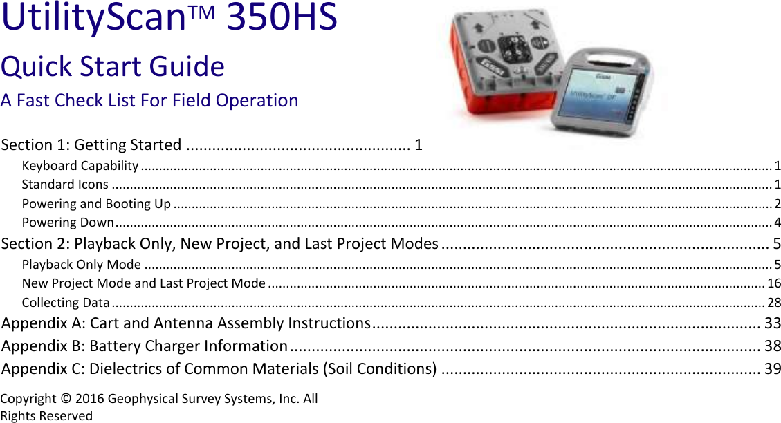
Geophysical Survey Systems 350HS The Utility Scan 350HS is a GPR concrete scanner User Manual
Geophysical Survey Systems, Inc. The Utility Scan 350HS is a GPR concrete scanner Users Manual
UserManual.wiki
>
Geophysical Survey Systems
>
350HS User Manual
Users Manual
Navigation menu
Upload a User Manual
Namespaces
Wiki Guide
HTML
PDF
Info
Views
User Manual
Discussion / Help
Navigation

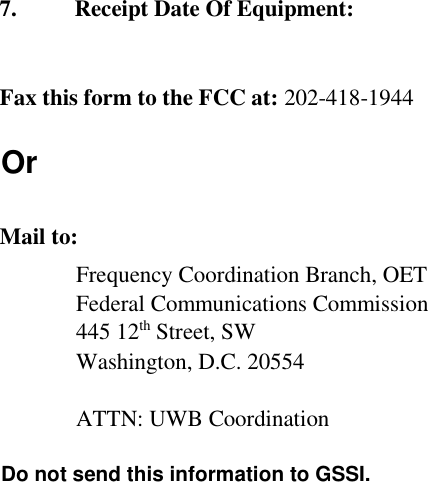
![Ground Penetrating Radar Coordination Notice And Equipment Registration Note: This form is only for Domestic United States users. The Federal Communications Commission (FCC) requires that all users of GPR who purchased antennas after July 15th, 2002 register their equipment and areas of operation. It is required that you fill out this form and fax or mail to the FCC. Failure to do this is a violation of Federal law. 1. Date: 2. Company name: 3. Address: 4. Contact Information [contact name and phone number]:](https://usermanual.wiki/Geophysical-Survey-Systems/350HS/User-Guide-2916750-Page-56.png)
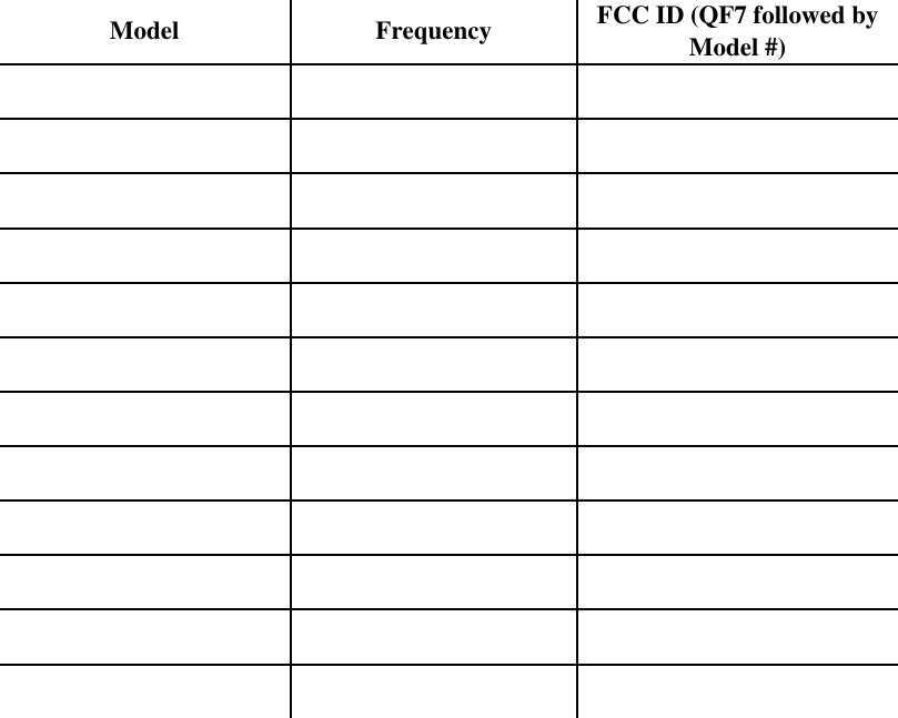
![5. Area Of Operation [state(s)]: ---Continued on next page. 6. Equipment Identification: Brand Name: Geophysical Survey Systems, Inc. Antenna Model No. (center frequency): List all antennas being registered.](https://usermanual.wiki/Geophysical-Survey-Systems/350HS/User-Guide-2916750-Page-57.png)