Geophysical Survey Systems D50300800 Ground Penetrating Radar Antenna User Manual
Geophysical Survey Systems, Inc. Ground Penetrating Radar Antenna Users Manual
Users Manual
Copyright © 2012 Geophysical Survey Systems, Inc. MN72-489 Rev -
All Rights Reserved
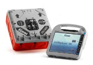
UtilityScanTM DF
Quick Start Guide
A Fast Check List For Field Operation
Section 1: Getting Started.................................................................................................................................... 2
Keyboard Capability ............................................................................................................................................... 2
ToughBook Information ....................................................................................................................................... 3
Standard Icons ......................................................................................................................................................... 4
Display Channel (Frequency) Icons .................................................................................................................. 4
Powering and Booting Up ................................................................................................................................... 5
Powering Down ....................................................................................................................................................... 7
Section 2: Playback Only, New Project, and Last Project Modes ............................................................ 8
Playback Only Mode .............................................................................................................................................. 8
New Project Mode and Last Project Mode ................................................................................................. 20
Collecting Data ..................................................................................................................................................... 32
Appendix A: Cart and Antenna Assembly Instructions............................................................................ 35
Appendix B: Battery Charger Information .................................................................................................... 42
Appendix C: Dielectrics of Common Materials (Soil Conditions) ......................................................... 43
Appendix D: Examples of Some Common Objects ................................................................................... 44
Appendix E: Glossary of Terms ......................................................................................................................... 49

Limited Warranty, Limitations Of Liability And Restrictions
Geophysical Survey Systems, Inc. hereinafter referred to as GSSI, warrants that for a period of 24 months from the
delivery date to the original purchaser this product will be free from defects in materials and workmanship. EXCEPT
FOR THE FOREGOING LIMITED WARRANTY, GSSI DISCLAIMS ALL WARRANTIES, EXPRESS OR IMPLIED,
INCLUDING ANY WARRANTY OF MERCHANTABILITY OR FITNESS FOR A PARTICULAR PURPOSE. GSSI's
obligation is limited to repairing or replacing parts or equipment which are returned to GSSI, transportation and insurance
pre-paid, without alteration or further damage, and which in GSSI's judgment, were defective or became defective during
normal use.
GSSI ASSUMES NO LIABILITY FOR ANY DIRECT, INDIRECT, SPECIAL, INCIDENTAL OR CONSEQUENTIAL
DAMAGES OR INJURIES CAUSED BY PROPER OR IMPROPER OPERATION OF ITS EQUIPMENT, WHETHER
OR NOT DEFECTIVE.
Before returning any equipment to GSSI, a Return Material Authorization (RMA) number must be obtained. Please call
the GSSI Customer Service Manager who will assign an RMA number. Be sure to have the serial number of the unit
available
Regulatory Information
Please see the GSSI Manual CD or our website, www.geophysical.com/regulatoryinformation.htm, for current
information and FCC Registration Form, including:
• FCC Notice for U.S. Customer
• Canadian Requirements for RSS-220
• Declaration of CE Conformance
Quick Start Guide UtilityScan DF
Copyright © 2012 Geophysical Survey Systems, Inc. 1
All Rights Reserved
UtilityScanTM DF
3
2
1
1
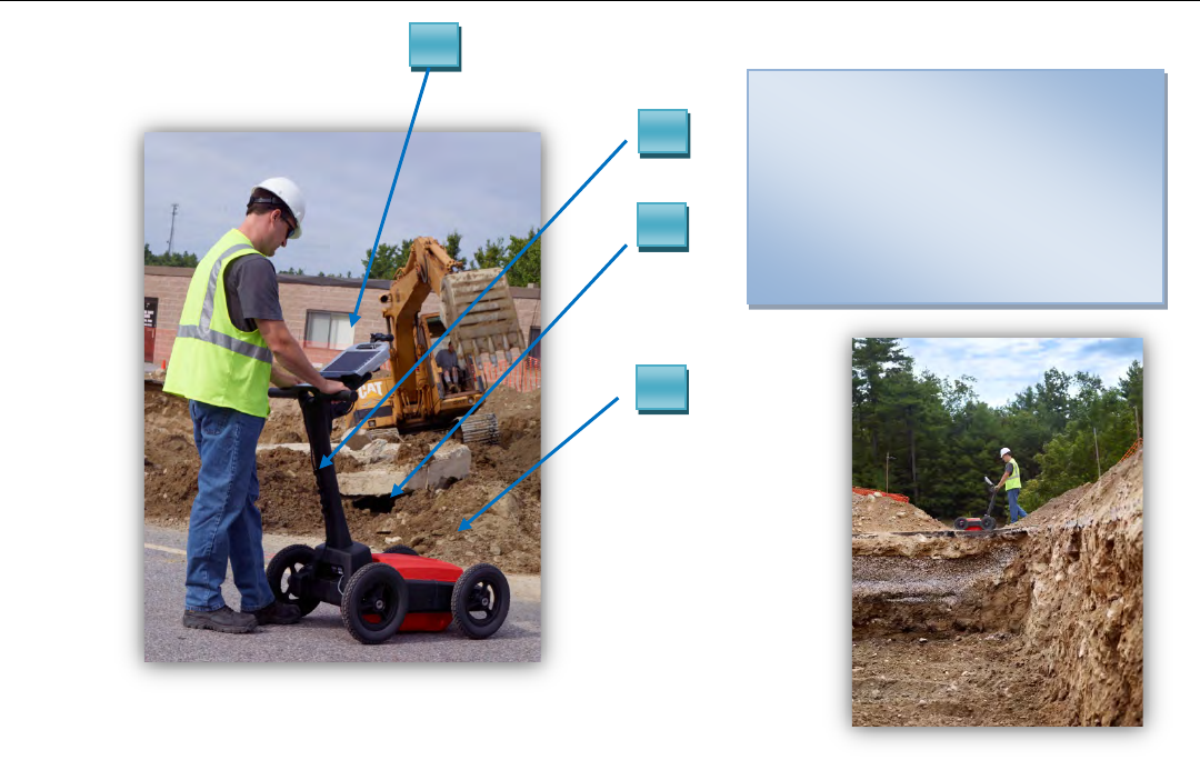
Control Unit (ToughBook H2)
22.0 m Control Cable
34 Wheel Cart
4Foam Insert and Dual Frequency
Antenna with battery inside the
Capsule
4
Quick Start Guide UtilityScan DF
Copyright © 2012 Geophysical Survey Systems, Inc. 2
All Rights Reserved
Section 1: Getting Started
Keyboard Capability
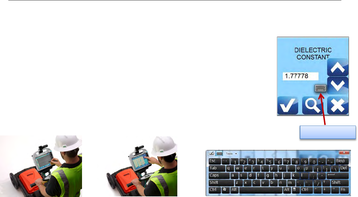
The Panasonic CF-H2 ToughBook is designed to be used as a touch screen. You may use your
fingers to tap on an icon or menu option, or you may use the attached stylus pen.
There is also keyboard capability on the screen of the ToughBook. A keyboard “Tab” is located
at the top left side of the screen. You may tap on the tab and a full keyboard will slide to the
middle of the screen.
At times, when data input (typing) is needed, you may simply tap on the white area of the screen
where text and/or numbers may be input. A small keyboard will appear on the screen. Tap on
the small keyboard and a large keyboard is displayed. Simply tap on the appropriate keys and
tap Return when you are done.
You may exit the keyboard by tapping on the “X” located on the upper right hand corner of the keyboard.
Small Keyboard

Quick Start Guide UtilityScan DF
Copyright © 2012 Geophysical Survey Systems, Inc. 3
All Rights Reserved
ToughBook Information
• The lights under the battery (1 and 2) indicate how much power is left in each battery. The lights will be green,
yellow and red.
• A battery may be replaced while the system is on. The system will run off of one battery while the other one is
being replaced.
Quick Start Guide UtilityScan DF
Copyright © 2012 Geophysical Survey Systems, Inc. 4
All Rights Reserved
Standard Icons
There are icons that will perform the same function throughout the system. They are as follows:
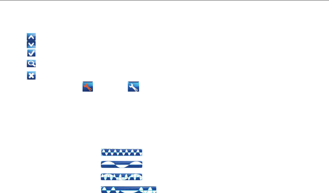
• Change values up or down, or highlight menu options or files.
• Accept the value.
• Test the value.
• Cancel.
The icons will display as red or white, depending upon whether or not it was the most recent selected
option.
Display Channel (Frequency) Icons
These icons will indicate what type of display is on the screen. Also, by tapping on them, will change the display
accordingly
• High Frequency (800 mhz)
• Low Frequency (300 mhz)
• Blend
• All Three
Quick Start Guide UtilityScan DF
Copyright © 2012 Geophysical Survey Systems, Inc. 5
All Rights Reserved
Powering and Booting Up
1 Assemble the cart as shown in Appendix A: Cart Assembly Instructions.
Important: Antenna battery must be attached to the antenna before continuing to Step 2.
2 To power up the system:
a) Press and hold the power button on the ToughBook for
about 2 seconds until a green light illuminates above the
power button. A green light will blink on the antenna
during the system boot up. It will be off when the boot up
process is complete. This green light will illuminate when
communication is re-established.
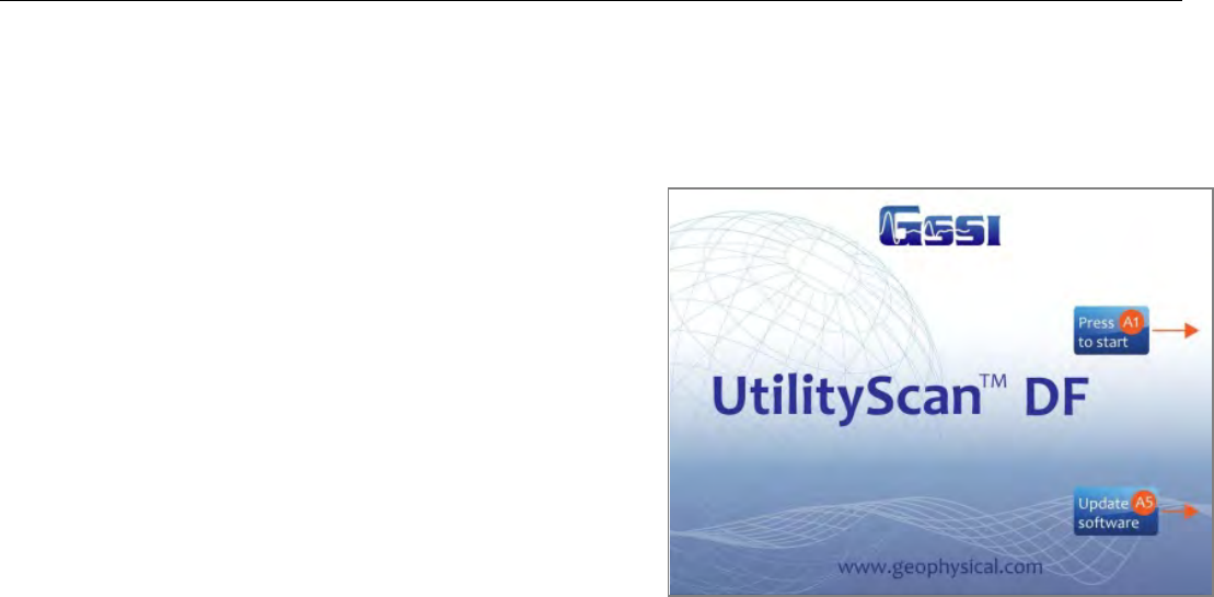
b) After a few seconds, when the system boot up is complete,
the UtilityScan DF Start Screen is displayed.
c) Tap either:
• A1 Icon or press the A1 button to start.
• A5 Icon or press the A5 button to update system
software.
Quick Start Guide UtilityScan DF
Copyright © 2012 Geophysical Survey Systems, Inc. 6
All Rights Reserved
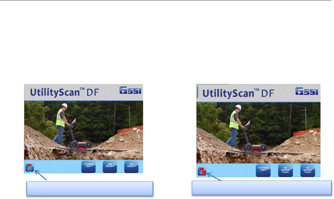
3 Select (by tapping) one of three Modes:
• Playback Only: To playback data previously collected and saved.
• New Project: To configure and collect data for a new project.
• Last Project: Collect data using the same configuration as the last project.
Note: If there is no communication between the ToughBook and the antenna, or there is no antenna attached to
the ToughBook, “New Project” and “Last Project” will display as “No Antenna Found”. The green light on the
antenna will illuminate if communication is established.
Communication Established with Antenna No Communication Established with Antenna
Quick Start Guide UtilityScan DF
Copyright © 2012 Geophysical Survey Systems, Inc. 7
All Rights Reserved
Powering Down
It is essential that these steps are followed in order when powering down the system.
Failure to do so may result in boot-up issues*.
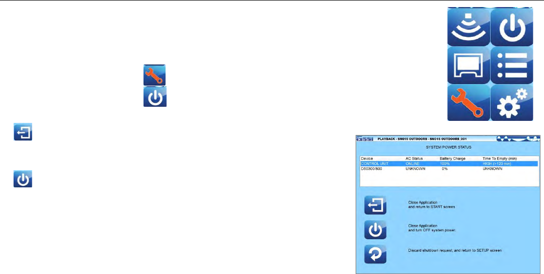
1 Tap on System Options.
2 Tap on System Shutdown.
3 Tap either:
• Exit: Close Application to return to start screen. At this point,
press and hold the power button for about 3 seconds.
The system will shut down properly.
• Power Off: Close Application and turn OFF System power.
The system will automatically shut down. (Recommended)
* If the system was not powered down properly and before the next time you
power up, you must remove and disconnect the battery on the antenna, the re-
connect it. This will turn the antenna off, then back on. You can now power
up normally.
Quick Start Guide UtilityScan DF
Copyright © 2012 Geophysical Survey Systems, Inc. 8
All Rights Reserved
Section 2: Playback Only, New Project, and Last Project Modes
Playback Only Mode
The Playback Only mode allows you to view and edit data previously collected and
saved.
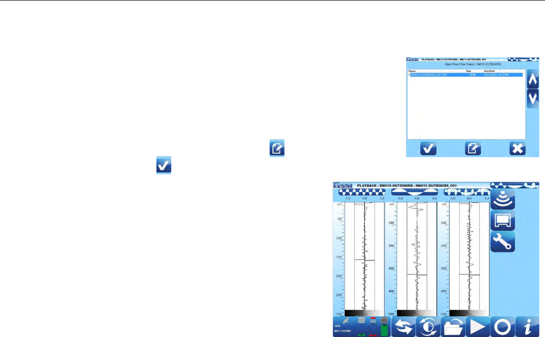
After selecting Playback Only, select which file you would like to review:
a) Tap on the arrows to highlight a file.
b) Tap on the Select Icon to select or de-select a file.
c) Tap on the Accept Icon.
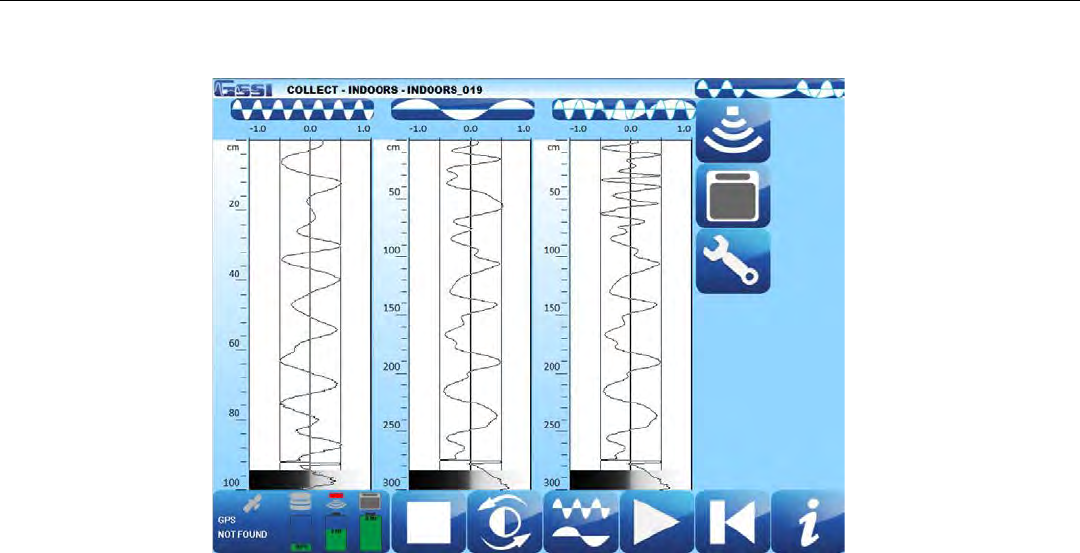
You will see the data in the O-Scope view change as if the data is
scrolling across the screen. You may stop the scrolling by tapping on
the Stop Icon (This will toggle between Stop Icon and Preview File
Icon. The Preview File Icon will continue the scrolling).
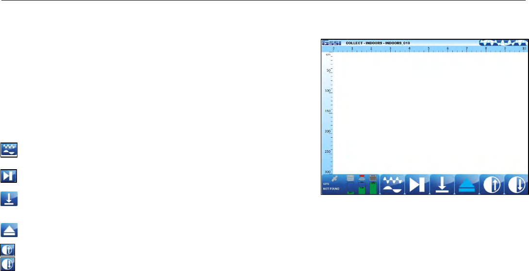
The Screen is divided into three sections: Data View (O-Scope), Main
Menu located at the right pane of the screen, and the Sub-Menu located
at the bottom of the screen.
Quick Start Guide UtilityScan DF
Copyright © 2012 Geophysical Survey Systems, Inc. 9
All Rights Reserved
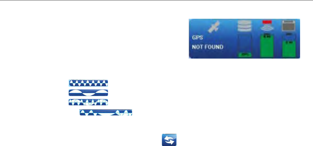
A Status screen located at the lower left corner of the screen. They indicate:
• GPS Status.
• Disk Space Used (storage space).
• Battery Power remaining for the antenna.
• Battery Power remaining for the ToughBook.
The Data View screen will display data in any one of the follow views:
• High Frequency
• Low Frequency
• Blend
• All Three (Default)
You may display just one frequency at a time by tapping the icon at the top of the O-Scope. Tapping the same icon will
display all three modes again.
When changing displays, you must tap the Preview File icon to re-display the O-Scope data.
Quick Start Guide UtilityScan DF
Copyright © 2012 Geophysical Survey Systems, Inc. 10
All Rights Reserved
High, Low, Blend, and Active Frequency Symbols
High Frequency
Low Frequency
Blend
Active Display
Quick Start Guide UtilityScan DF
Copyright © 2012 Geophysical Survey Systems, Inc. 11
All Rights Reserved
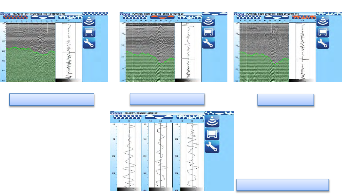
Low Frequency Display
High Frequency Display
Blend Display
Both Frequencies plus Blend
Quick Start Guide UtilityScan DF
Copyright © 2012 Geophysical Survey Systems, Inc. 12
All Rights Reserved
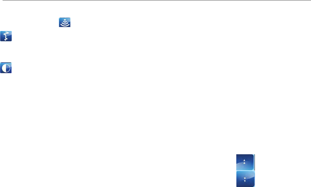
Main Menu Options (Right Pane of the Screen)
Scan Process Icon
• Scan
• Dielectric Constant: Enter the Dielectric of the soil (See Appendix C for more Dielectric information).
• Soil Type: Determine the soil conditions. This will change the Dielectric Value.
• Gain Settings
• Gain Mode
• Auto allows the system to configure the Gain.
• Manual allows the user to configure the Gain.
• Number of Points (Only if Gain Mode is set to Manual)
• Number of points or “Individual Sections” to adjust the Gain.
• Ranges for 1 point to 8 points.
• GP1: 8 (Only if Gain Mode is set to Manual)
• Depending upon number of Gain Points, adjust each section accordingly.
• Values range from -42 to 126.
Note: Tap on the double arrows (up or down) to display the appropriate gain points.

Quick Start Guide UtilityScan DF
Copyright © 2012 Geophysical Survey Systems, Inc. 13
All Rights Reserved
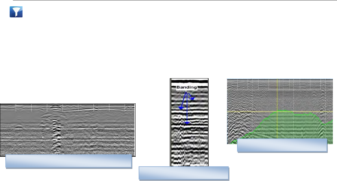
• Filters (See Appendix E for more information)
• Stacking: To reduce random or high frequency noise in your data.
• Background Removal: Remove horizontal banding in your data.
• Noise Indicator
• On: Display approximately the depth where data becomes too weak.
• Off: Turn off display.
High Frequency Noise (Fuzziness) Example
Horizontal Banding Example
Noise Indicator Example

Quick Start Guide UtilityScan DF
Copyright © 2012 Geophysical Survey Systems, Inc. 14
All Rights Reserved
Output Options Icon
• Display:
• Color Table: Select a color scheme.
• Color Xform: Select how to distribute the color scheme throughout the scale (bar is negative to positive).
• Dual Channel
• Split: both channels to be displayed separately.
• Blend: both channels are blended together.
• Vertical Scale
• Equal: Scales are equal.
• Real: Scales are set to scale as per antenna depth range.

Quick Start Guide UtilityScan DF
Copyright © 2012 Geophysical Survey Systems, Inc. 15
All Rights Reserved
• Manage Files:
• Data Path: Change the Data Path where you would like the data to be written or opened from.
• Copy to USB Device: Copies the data from the Data Path to the USB device.
• Move to USB Device: Copies the data from the Data Path AND DELETES those files from the ToughBook.
• Delete Files: Delete files from the ToughBook.
• Units/Scale:
• Depth Scale
• Depth: Display the Scale in distance units.
• Time: Display the Scale in time units.
• Depth Units: Select the unit of measurement for depth or the vertical scale.
• Ticks per Unit: Number of ticks for marking the data (short line).
• Ticks per Major Unit: Number of ticks for each major unit (long line).

Quick Start Guide UtilityScan DF
Copyright © 2012 Geophysical Survey Systems, Inc. 16
All Rights Reserved
System Options Icon
• System Shut Down
• Exit: Close Application and Return to Start Screen.
• Power Off: Close Application and Shut Down the System (power off) .
• Return to Application: Discard Shutdown Request and Return to Setup Screen.
• Versions: Displays Version Numbers of the software and firmware
• User Interface
• Language: Set Language.
• Button Design
• Label: Text Icons.
• Symbol: Pictured Icons.
• Brightness Up or Down: Set contrast up or down.
Quick Start Guide UtilityScan DF
Copyright © 2012 Geophysical Survey Systems, Inc. 17
All Rights Reserved
Sub Menu Options (Bottom Pane of the Screen)
• Preview File/Stop: Preview file. This will toggle between Preview File and Stop.
• Reset Gain: Reset the display gain for optimal viewing.
• Select File: Select another file to playback.
• Playback File(s): Display the RADAR data in whatever display you selected as a display (High, Low, or Blend).
See next section for options on this screen.
• Collect Mode: This will take you to collect mode if you wish to collect data.
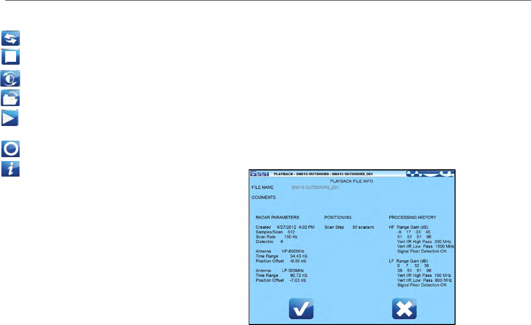
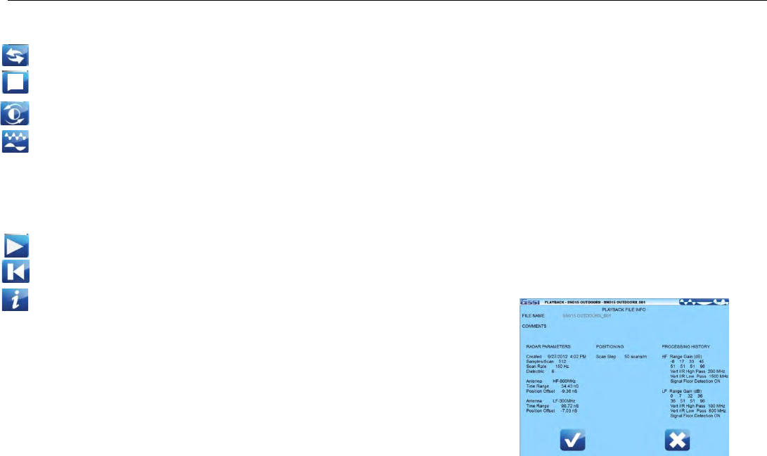
• File Info: Information about the file.
Quick Start Guide UtilityScan DF
Copyright © 2012 Geophysical Survey Systems, Inc. 18
All Rights Reserved
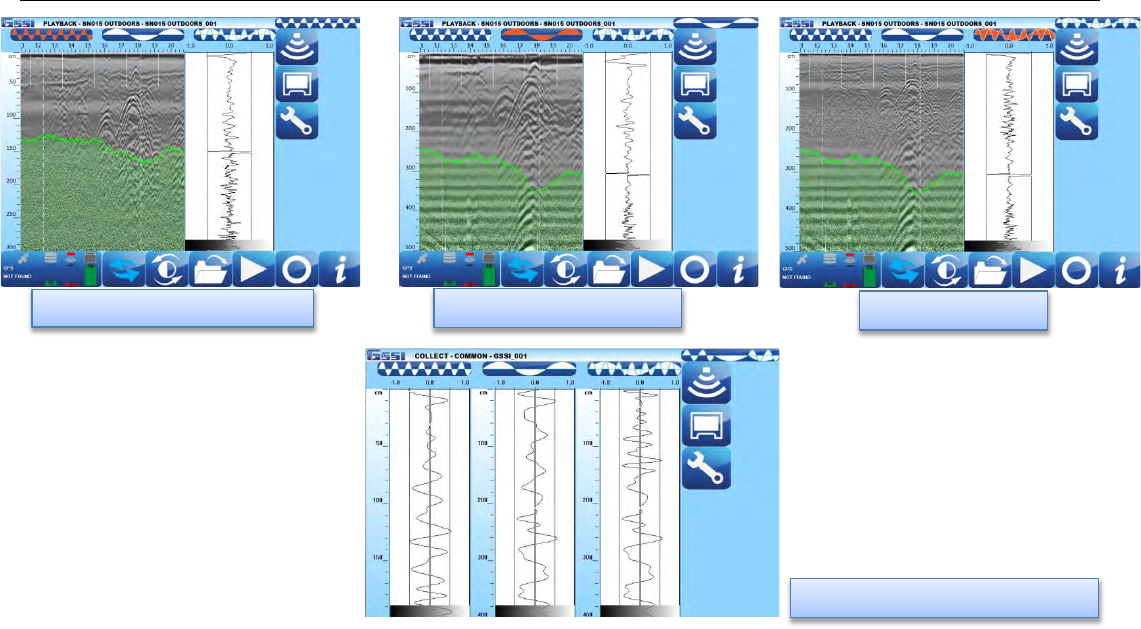
Playback File(s) Options
Depending upon the type of display you selected in the previous screen,
the data will display in the same mode (High, Low, or Blend)
Displayed at the top of the screen:
• The name of the file.
• The location of the cross hair (X for distance, Z for depth). Place
the stylist pen on the screen to move the cross hair to the desired
position.
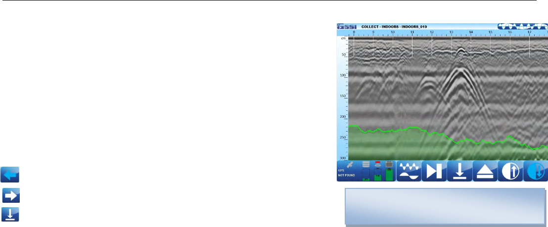
Menu Options at the Bottom of the Screen
• Cursor Left: Scroll the data towards the beginning of the file.
• Cursor Right: Scroll the data towards the end of the file.
• Mark: Mark the data for reference points.
a) Place the stylist pen on the screen.
b) Move the pen around and place the vertical line where you would like the mark to be placed.
c) Tap the Mark Icon.
In this example, the Noise Indicator is turned
on, as indicated by the green shaded area.
Quick Start Guide UtilityScan DF
Copyright © 2012 Geophysical Survey Systems, Inc. 19
All Rights Reserved
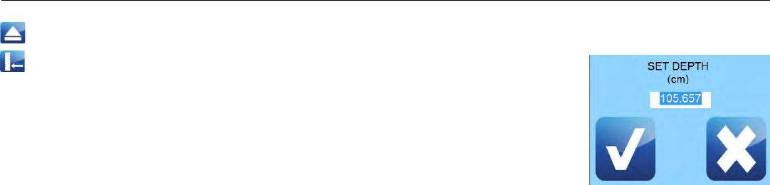
• Stop Playback: Return to the Main Playback Screen.
• Set Depth: Indicate a known depth in your data. This will update the dielectric
value accordingly.
a) Place the stylist pen on the screen.
b) Move the pen around and place the horizontal line on the known depth.
c) Tap the Set Depth Icon.
d) Enter and accept the known depth.
Quick Start Guide UtilityScan DF
Copyright © 2012 Geophysical Survey Systems, Inc. 20
All Rights Reserved
New Project Mode and Last Project Mode
• New Project Mode will allow you to configure the system as desired for a new project or continue with an old
project.
• Last Project Mode will bypass the Folder selection screen and continue with the last project with all its settings
from the last project. In this mode, you still can make changes to the settings.
• In either mode, the options are the same.
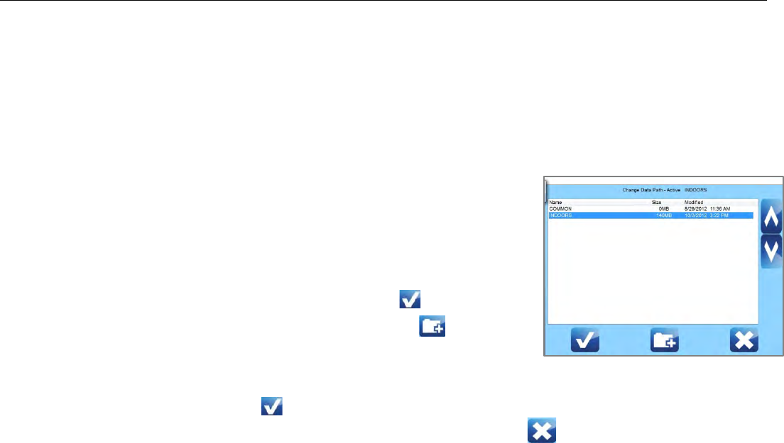
After selecting New Project, select which folder you would like to save your data, or
create a new folder for a new project.
You may do one of the following:
a) Tap on the arrows and select a folder (project. All files save will be saved to
this folder and the name of the files will be folder name + a sequential
number. Tap on Accept to the continue.
b) Tap on New Data Path to create a new folder (project).
• Enter and save the new folder (project) name.
• Highlight the new folder (project) by tapping on the arrows.
• Tap on Accept to continue.
c) Tap on Cancel. The files will be saved to the last folder that was used.
Quick Start Guide UtilityScan DF
Copyright © 2012 Geophysical Survey Systems, Inc. 21
All Rights Reserved
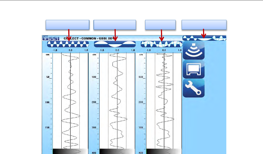
d) Once you have selected a folder, the following screen is displayed or you selected Last Project Mode:
The Screen is divided into three sections: Data View (O-Scope), Main Menu located at the right pane of the screen, and
the Sub-Menu located at the bottom of the screen
Quick Start Guide UtilityScan DF
Copyright © 2012 Geophysical Survey Systems, Inc. 22
All Rights Reserved
Low Frequency Display
High Frequency Display
Blend Display
Both Frequencies plus Blend

Quick Start Guide UtilityScan DF
Copyright © 2012 Geophysical Survey Systems, Inc. 23
All Rights Reserved
Main Menu Options (Right Pane of the Screen)
Scan Process Icon
• Scan
• Depth Range: Enter the depth penetration.
• Dielectric Constant: Enter the Dielectric of the soil (See Appendix C for more Dielectric information).
• Soil Type: Determine the soil conditions. This will change the Dielectric Value.
• Scan Density: Set number of scans per unit (meter or feet).
• High (100 scans/m, 30 scans/ft)
• Normal (50 scans/m, 15 scans/ft)
• AutoSave File
• Off: User is prompted to save a file.
• On: System will automatically save a file.

Quick Start Guide UtilityScan DF
Copyright © 2012 Geophysical Survey Systems, Inc. 24
All Rights Reserved
• Gain Settings
• Gain Mode
• Auto allows the system to configure the Gain.
• Manual allows the user to configure the Gain.
• Number of Points (Only if Gain Mode is set to Manual)
• Number of points or “Individual Sections” to adjust the Gain.
• Ranges for 1 point to 8 points.
• GP1: 8 (Only if Gain Mode is set to Manual)
• Depending upon number of Gain Points, adjust each section accordingly.
• Values range from -42 to 126.
Note: Tap on the double arrows (up or down) to display the appropriate gain points.
Quick Start Guide UtilityScan DF
Copyright © 2012 Geophysical Survey Systems, Inc. 25
All Rights Reserved
• Filters (See Appendix E for more information)
• Stacking: To reduce random or high frequency noise in your data.
• Background Removal: Remove horizontal banding in your data.
• Noise Indicator
• On: Display approximately the depth where data becomes too weak.
• Off: Turn off display.
High Frequency Noise (Fuzziness) Example
Horizontal Banding Example
Noise Indicator Example

Quick Start Guide UtilityScan DF
Copyright © 2012 Geophysical Survey Systems, Inc. 26
All Rights Reserved
• Maintenance
• Calibrate SW: Select this option to calibrate the survey wheel.
a) Enter Calibration Distance.
b) Position Antenna on Start Mark.
c) Tap on Start.
d) Move Antenna to End Mark.
e) Tap on Accept.
• Configure GPS: Select this option to configure this system with your GPS.
• Set Time: Select this option to set Date and Time.

Quick Start Guide UtilityScan DF
Copyright © 2012 Geophysical Survey Systems, Inc. 27
All Rights Reserved
Output Options Icon
• Display:
• Color Table: Select a color scheme.
• Color XForm: Select how to distribute the color scheme throughout the scale (bar is negative to positive).
• Dual Channel
• Split: Both channels to be displayed separately.
• Blend: Both channels are blended together.
• Vertical Scale
• Equal: Scales are equal.
• Real:Scales are set to scale as per antenna depth range.

Quick Start Guide UtilityScan DF
Copyright © 2012 Geophysical Survey Systems, Inc. 28
All Rights Reserved
• Manage Files:
• Data Path: Change the Data Path where you would like the data to be written or opened from.
• Copy to USB Device: Copies the data from the Data Path to the USB device.
• Move to USB Device: Copies the data from the Data Path AND DELETES those files from the ToughBook.
• Delete Files: Delete files from the ToughBook.
• Units/Scale:
• Depth Scale
• Depth: Display the Scale in distance units.
• Time: Display the Scale in time units.
• Depth Units: Select the unit of measurement for Depth or the vertical scale.
• Ticks per Unit: Number of ticks for marking the data (short line).
• Ticks per Major Unit: Number of ticks for each major unit (long line).
Quick Start Guide UtilityScan DF
Copyright © 2012 Geophysical Survey Systems, Inc. 29
All Rights Reserved
System Options Icon
• System Shut Down
• Exit: Close Application and Return to Start Screen.
• Power Off: Close Application and Shut Down the System (power off).
• Return to Application: Discard Shutdown Request and Return to Setup Screen.
• Versions: Displays Version Numbers of the software and firmware
• User Interface
• Language: Set Language.
• Button Design
• Label: Text Icons.
• Symbol: Pictured Icons.
• Brightness Up or Down: Set contrast up or down
• Save Setup: Save a current configuration for future use.
• Recall Setup: Recall a saved configuration.
Quick Start Guide UtilityScan DF
Copyright © 2012 Geophysical Survey Systems, Inc. 30
All Rights Reserved
Sub Menu Options (Bottom Pane of the Screen)
• Stop/Preview Scan: This will turn the antenna off and on. This will toggle between Off and On.
• Reset Gain: Reset the display gain for optimal viewing.
• Active Channel: Display between the following modes.
• High Frequency
• Low Frequency
• Blend
• Start Scan: Begin collect of data.
• Playback Mode: This will take you to playback mode if you wish to view saved data.
• File Info: Information about the file. You may also change the file
names here as well. All file names will have a sequential number
attached to it.
Quick Start Guide UtilityScan DF
Copyright © 2012 Geophysical Survey Systems, Inc. 31
All Rights Reserved
Start Scan Options
Depending upon the type of display you selected in the previous screen,
the data will display in the same mode (High, Low, Split or Blend).
Displayed at the top of the screen:
• The name of the file.
• The display mode.
Menu Options at the Bottom of the Screen:
• Active Channel: Toggle between High, Low, or Blend
frequency displays.
• Next File: Save the current file and begin new file.
• Mark: Mark the data for reference points.
• Stop Scan: Save the current file and return to the Main Screen.
• Gain: Increase or decrease display gain.
Quick Start Guide UtilityScan DF
Copyright © 2012 Geophysical Survey Systems, Inc. 32
All Rights Reserved
Collecting Data
• If you plan to save the data you collect, note the file name located at the top left of the screen.
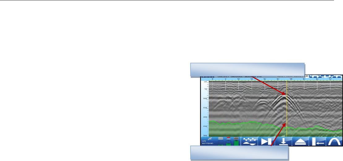
• Begin collecting data by moving the cart forward. Data gets collected only when the cart is moving forward.
• Once you start seeing hyperbolas on the screen, pull the system straight back along your survey line. You will
see a vertical line (the backup cursor) scroll along your data. When that vertical line is right over the apex of the
hyperbola, the center of the antenna is over that target.
• The center of the antenna is located in the middle of the
antenna directly under the capsule between the two centerline
indicators on each side of the cart. Using these as reference
points, mark the ground at each side of your cart. After
moving the cart, place an “X” between the two marks. Push
the cart straight forward or move the cart to do another line
scan. No data will be collected until you have passed the spot
where you started to reverse.
Hyperbola which represents a target
Vertical Line (Backup Cursor)
Quick Start Guide UtilityScan DF
Copyright © 2012 Geophysical Survey Systems, Inc. 33
All Rights Reserved
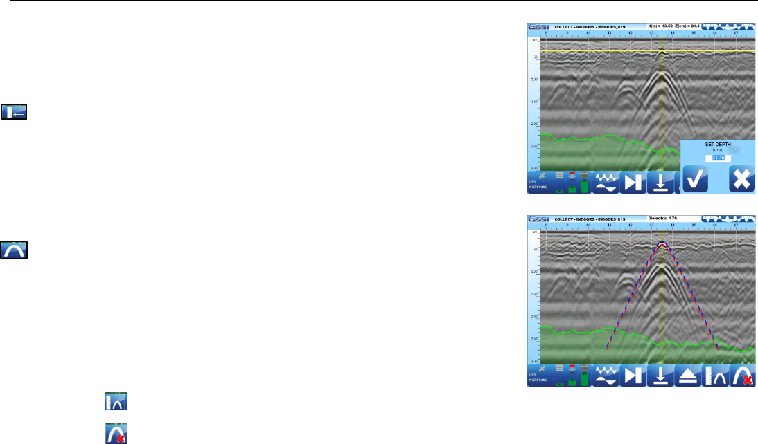
Set Depth and Focus Data
This will allow you to enter a known depth or migrate the data to re-establish a
dielectric value. Note that two icons at the bottom have changed when the backup
cursor is displayed on the screen (when the cart was pushed backward.
• Set Depth
a) Using the stylus pen, place the horizontal line at a known depth.
b) Tap Set Depth.
c) Input the depth and accept. This will change the dielectric value.
• Focus On
a) Using the stylus pen, place the cross-hair on a hyperbola.
b) Tap on Focus On.
c) Using the stylus pen, match the Focus On hyperbola with a hyperbola on
the screen (width).
d) Tap on:
• Set Focus to accept the hyperbola. This will change the dielectric value.
• or Focus Off to cancel this process .
Quick Start Guide UtilityScan DF
Copyright © 2012 Geophysical Survey Systems, Inc. 34
All Rights Reserved
Blend Mode Display Example
Split Mode Display Example
High Frequency Display Example
Low Frequency Display Example
Quick Start Guide UtilityScan DF
Copyright © 2012 Geophysical Survey Systems, Inc. 35
All Rights Reserved
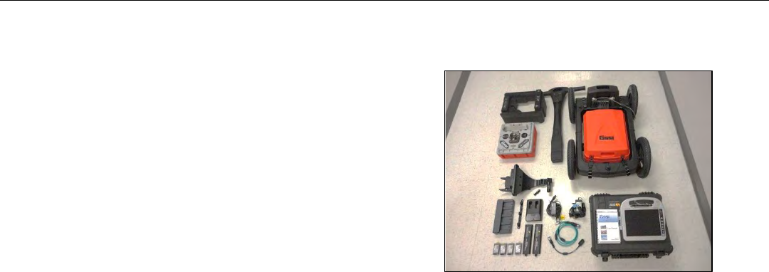
Appendix A: Cart and Antenna Assembly Instructions
1 Unpack your system.
• ToughBook H2 and Power Adapter
• 2.0 m Communcation Cable
• Power Cable, Battery and Charger
• Foam Insert
• DF Antenna
• 4 Wheel Cart with Capsule
• CPU Mounting Unit
• Manual CD and Quick Start Guide
• Battery Chargers for ToughBook and Antenna Batteries
• 4 ToughBook batteries
• 2 Antenna batteries
• Transit case
Quick Start Guide UtilityScan DF
Copyright © 2012 Geophysical Survey Systems, Inc. 36
All Rights Reserved
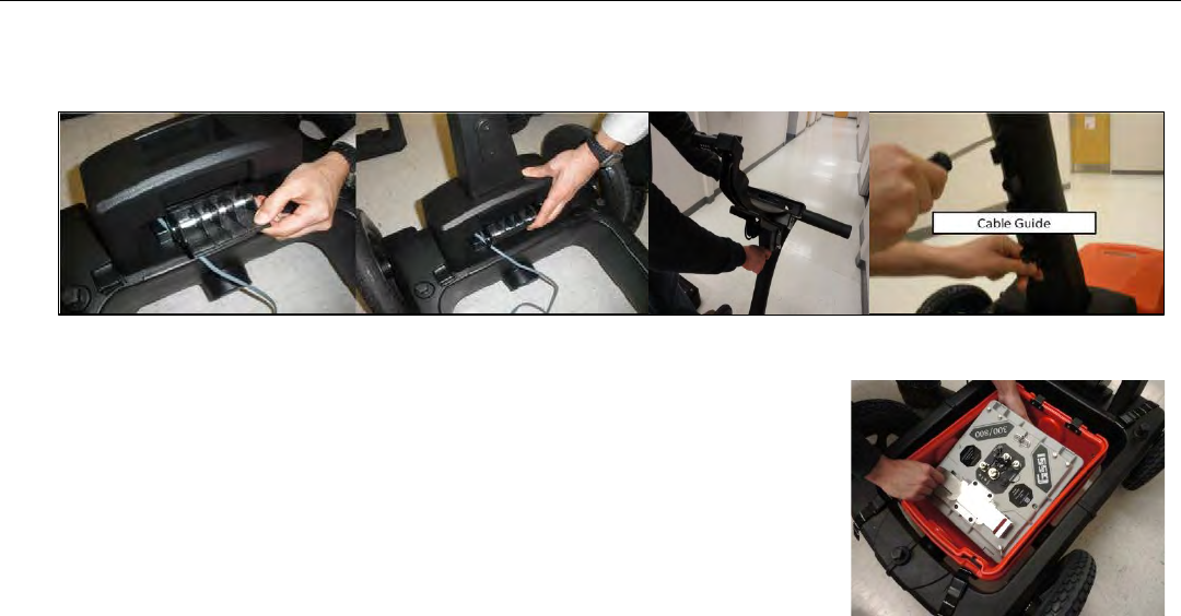
2 Assemble the handle to the cart as shown below. Attach the CPU Mounting Bracket and the Cable Guide to the
handle.
3 Insert the DF Antenna into the capsule. NOTE THE POSITION and THE DIRECTION of the antenna in the Capsule.
Quick Start Guide UtilityScan DF
Copyright © 2012 Geophysical Survey Systems, Inc. 37
All Rights Reserved
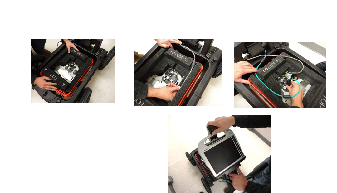
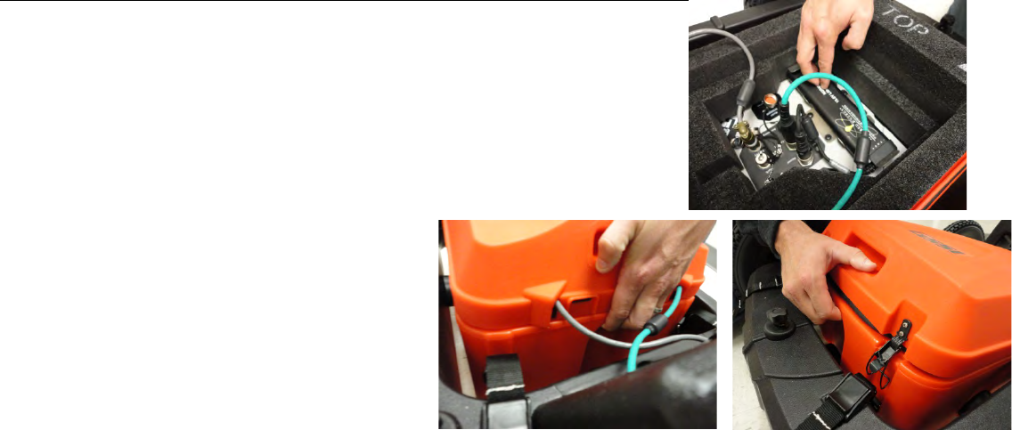
4 Guide the 2.0 m Communication Cable and the Survey Wheel cable through the foam as shown, using the slots of the
foam as guides. Attach the cables to the DF antenna as shown. NOTE the service loop of the cables to reduce the
tension on the cables.
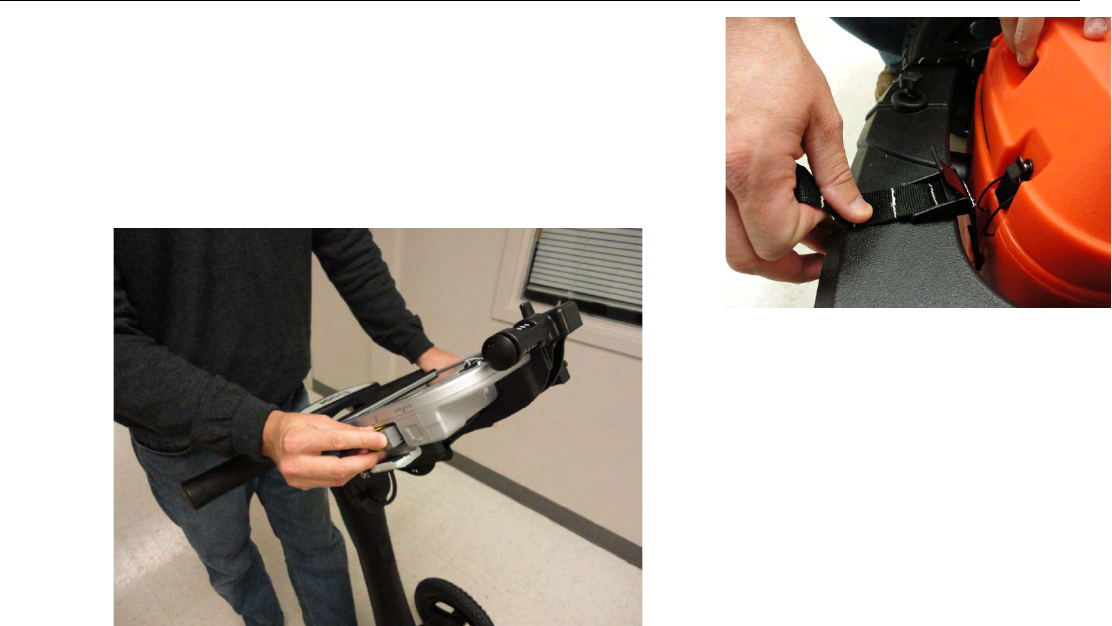
5 Attach the ToughBook to the mounting bracket.
Quick Start Guide UtilityScan DF
Copyright © 2012 Geophysical Survey Systems, Inc. 38
All Rights Reserved
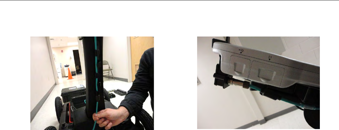
6 Guide the Green Communication Cable through the cable guide, through the hole at the top of the handle and connect
it to the ToughBook.
Quick Start Guide UtilityScan DF
Copyright © 2012 Geophysical Survey Systems, Inc. 39
All Rights Reserved
7 Connect the battery cable and insert the Antenna Battery to the battery mount on
the antenna.
8 Place the cover of the capsule, starting in the
back as shown. Make certain there is service loop
with the cables so that there is no tension with
the cables as the capsule moves up and down
during data collection. Latch the cover to the lock
position.
Quick Start Guide UtilityScan DF
Copyright © 2012 Geophysical Survey Systems, Inc. 40
All Rights Reserved
9 Depending on site conditions and to increase the life of the capsule, you
should adjust the height of the capsule by using a strap. Place a ¼ inch
piece of plywood under the capsule. Loosen the straps so that the capsule
sits on the plywood, then re-tighten the straps.
10 Insert the ToughBook batteries (2), one on each side of the ToughBook.
Quick Start Guide UtilityScan DF
Copyright © 2012 Geophysical Survey Systems, Inc. 41
All Rights Reserved
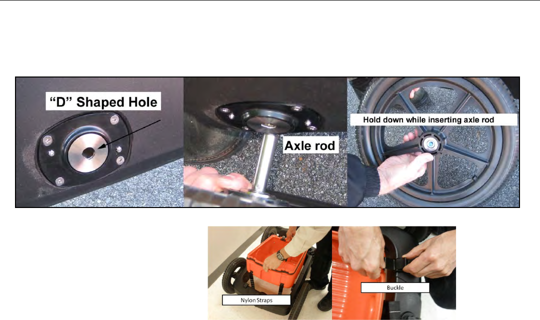
Though the wheels and the capsule come attached to the cart, you may need to unattach and re-attach them. To detach or
attach wheels to cart frame. Line up the flat side of the “D” shaped axle rod with the corresponding flat part of the “D”
shaped hole on the cart frame. Slide the rod into the cart frame while keeping the blue button at the center of the wheel
hub depressed.
Attaching the Capsule to the Cart.
Quick Start Guide UtilityScan DF
Copyright © 2012 Geophysical Survey Systems, Inc. 42
All Rights Reserved
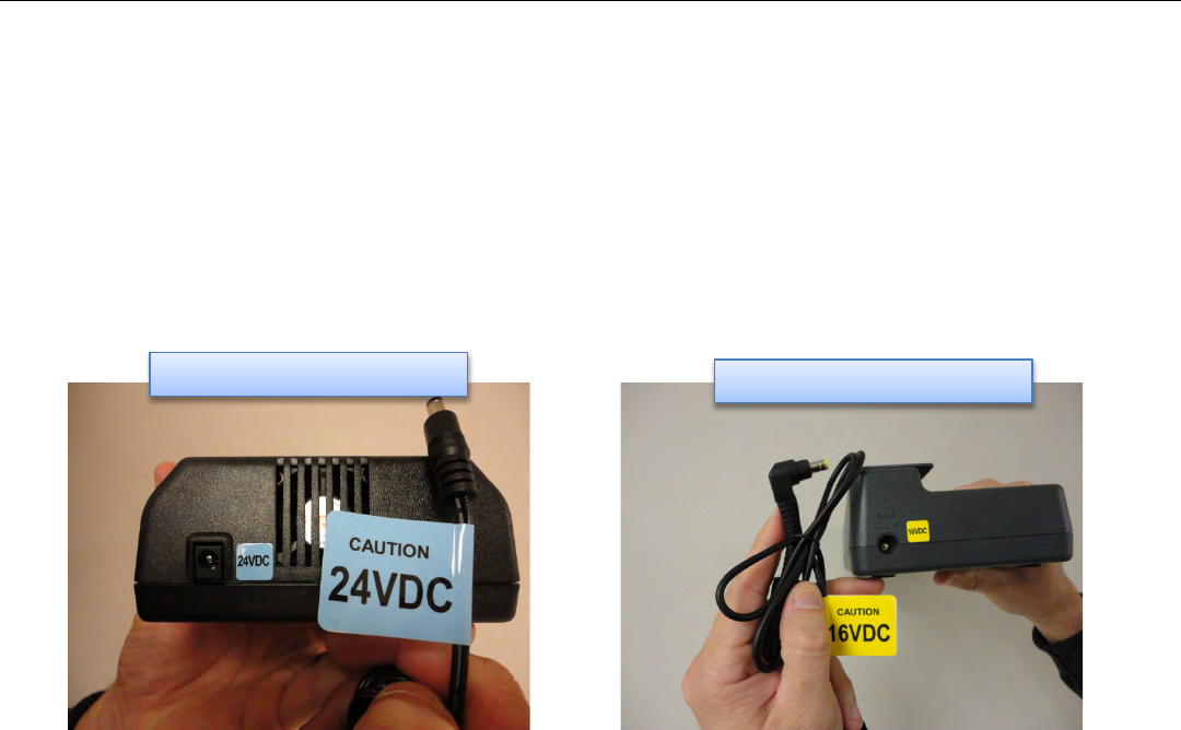
Appendix B: Battery Charger Information
There are two battery chargers included in your system.
• Charger for the Antenna batteries.
• Charger for the ToughBook batteries.
The cables for each are color coordinated so that cables are used with its corresponding charger.
Note: The cable for the ToughBook Battery Charger may also be used directly for the ToughBook as well.
Antenna Battery Charger
ToughBook Battery Charger

Quick Start Guide UtilityScan DF
Copyright © 2012 Geophysical Survey Systems, Inc. 43
All Rights Reserved
Appendix C: Dielectrics of Common Materials (Soil Conditions)
Material
Dielectric Constant
Material
Dielectric Constant
Air
1
Wet Granite
6.5
Snow Firn
1.5
Travertine
8
Dry Loamy/Clayey Soils
2.5
Wet Limestone
8
Dry Clay
4
Wet Basalt
8.5
Dry Sands
4
Tills
11
Ice
4
Wet Concrete
12.5
Coal
4.5
Volcanic Ash
13
Asphalt
5
Wet Sands
15
Dry Granite
5
Wet Sandy Soils
23.5
Frozen Sand & Gravel
5
Dry Bauxite
25
Dry Concrete
5.5
Saturated Sands
25
Dry Limestone
5.5
Wet Clay
27
Dry Sand & Gravel
5.5
Peats (saturated)
61.5
Potash Ore
5.5
Organic Soils (saturated)
64
Dry Mineral/Sandy Soils
6
Sea Water
81
Dry Salt
6
Water
81
Frozen Soil/Permafrost
6
Syenite Porphyry
6
Wet Sandstone
6
Quick Start Guide UtilityScan DF
Copyright © 2012 Geophysical Survey Systems, Inc. 44
All Rights Reserved
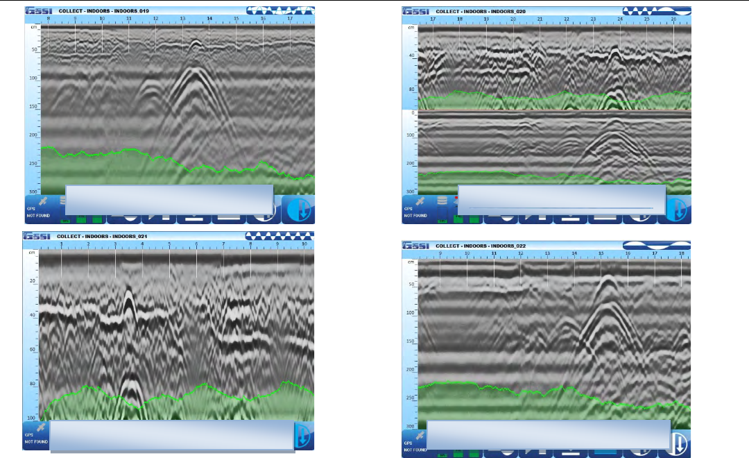
Appendix D: Examples of Some Common Objects
These examples are presented for informational use only. The images that you see on your own site conditions may vary.
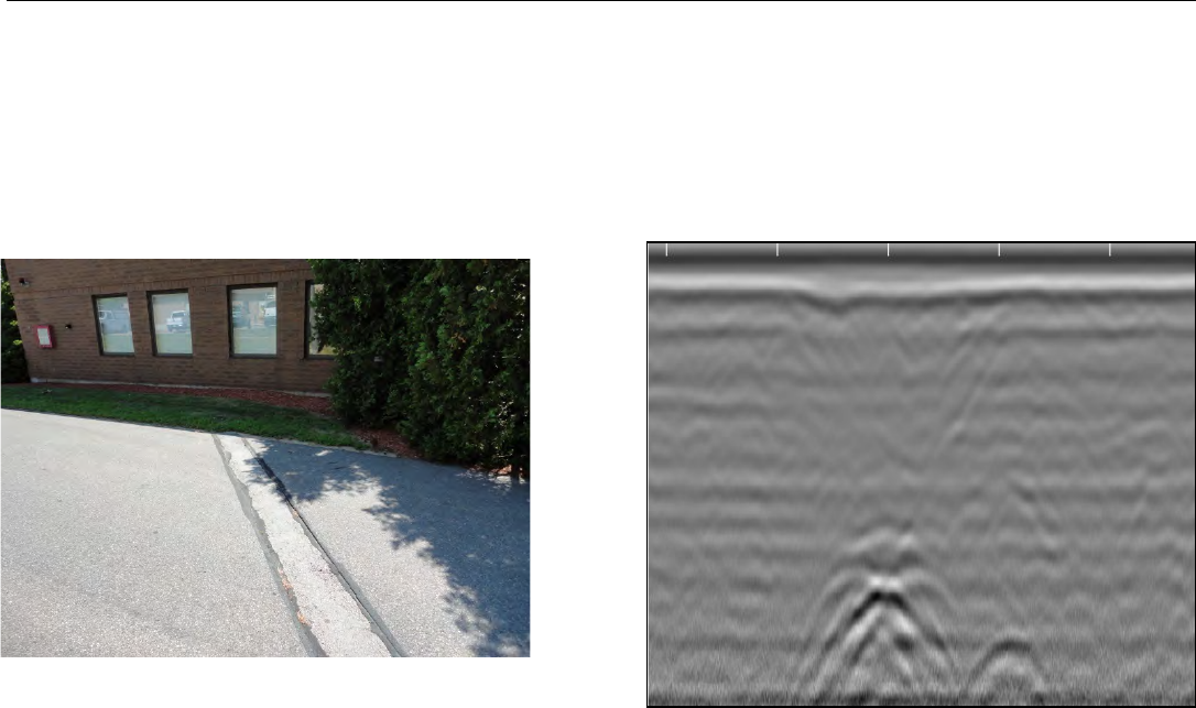
Example 1
This piece of data shows a bank of conduits feeding into an industrial building. Note the dipping edge of a trench cut
to the upper left of the conduits.
Quick Start Guide UtilityScan DF
Copyright © 2012 Geophysical Survey Systems, Inc. 45
All Rights Reserved
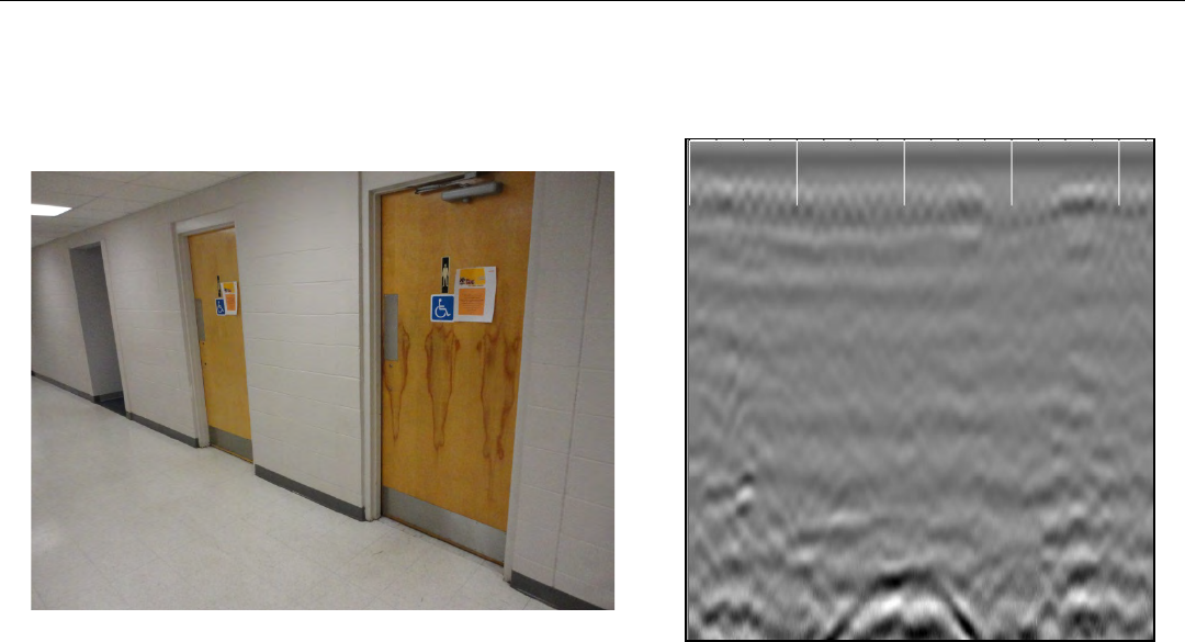
Example 2
This image shows a drain line coming out of a restroom. Also note the mesh at the top of the screen.
Quick Start Guide UtilityScan DF
Copyright © 2012 Geophysical Survey Systems, Inc. 46
All Rights Reserved
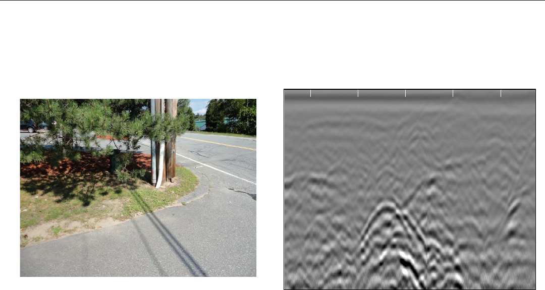
Example 3
This image shows data collected across a driveway, and locating a conduit from the telephone pole to an industrial
building.
Quick Start Guide UtilityScan DF
Copyright © 2012 Geophysical Survey Systems, Inc. 47
All Rights Reserved
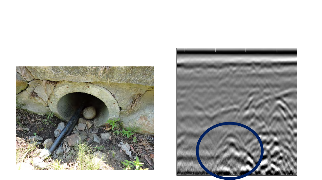
Example 4
This image shows data collected along a driveway next to a business. This shows a concrete culvert with a cable running
through it.
Quick Start Guide UtilityScan DF
Copyright © 2012 Geophysical Survey Systems, Inc. 48
All Rights Reserved
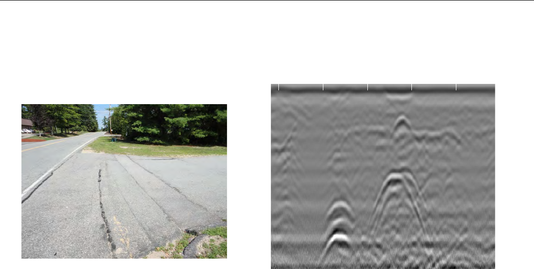
Example 5
This image shows a gas line and communication cables (Fiber Optic) going across a driveway
Quick Start Guide UtilityScan DF
Copyright © 2012 Geophysical Survey Systems, Inc. 49
All Rights Reserved
Appendix E: Glossary of Terms
Dielectric: A value assigned to materials and is used to calculate the velocity of RADAR in that material. RADAR will
travel at different speeds depending upon the material and/or soil condition. RADAR travels fastest in air (dielectric = 1)
and slowest in water (dielectric = 81). Everything else falls somewhere in between. It is important to know the dielectric
value of a material so that the depth of a target can be calculated. Since determining dielectric is a best guess estimate, the
depth of a target will never be an exact measurement. As a safety feature, you will always give about a 1 foot (or about
1/3 meter) margin of error when estimating the depth of a target.
Filter: A process to remove unwanted noise in the data so that targets can be seen more clearly. Filtering is a trial and
error process, therefore trial runs are necessary using different filtering values to determine the best configuration for a
job site. There are two types of filtering:
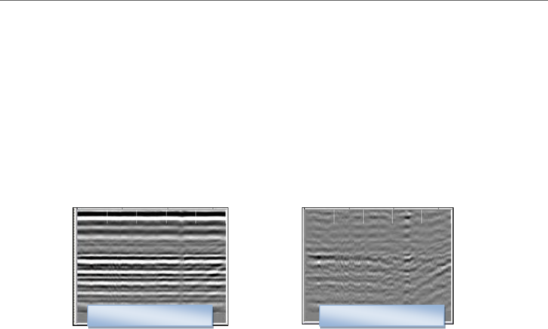
Background Removal: This filter will remove unwanted noise that looks like horizontal banding across your data.
Using this process, this will remove data that is consistent throughout your data.
No Background Removal
Background Removal
Quick Start Guide UtilityScan DF
Copyright © 2012 Geophysical Survey Systems, Inc. 50
All Rights Reserved
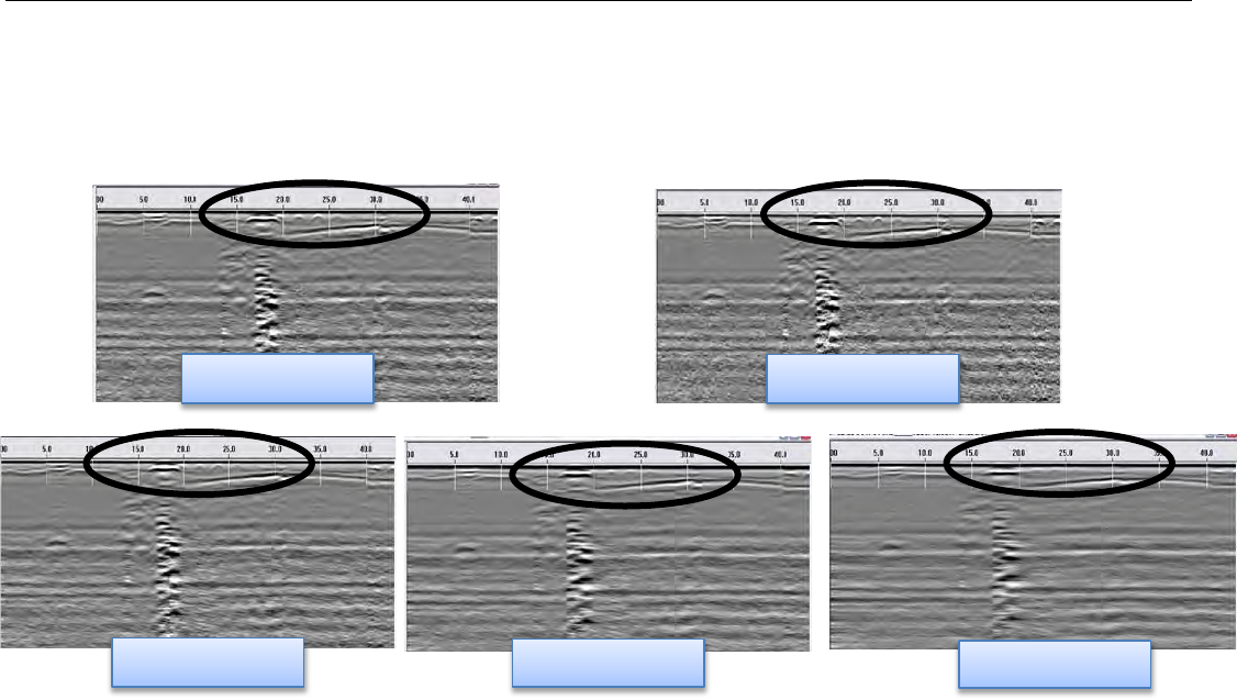
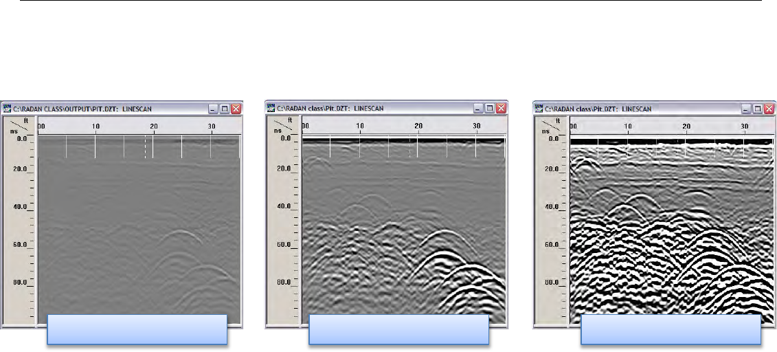
Stacking: This filter will remove unwanted noise that looks like fuzziness in your data. By selecting a value of 3, 5, 9, or
15, the process with take each scan and replace that scan with the average values of the surrounding scans. Be aware that
too much stacking can filter out real targets. In this example, stacking of 3 is the best result. Targets at the top begin to
disappear with higher scans to average.
No Stacking
Stacking = 3
Stacking = 15
Stacking = 9
Stacking = 5
Quick Start Guide UtilityScan DF
Copyright © 2012 Geophysical Survey Systems, Inc. 51
All Rights Reserved
Gain: Adding or subtracting Gain from data will amplify or lower the image of the RADAR signals. It is advised that you
use the lowest gain that will show targets.
Gain too low
Correct Gain
Gain too high
The following pages are additional documents
included in the GSSI Manual CD that ships with each
product.
FCC Notice (for U.S. Customers):
This device complies with part 15, class F of the FCC Rules:
Operation is subject to the following conditions:
1. This device many not cause harmful interference, and
2. This device must accept any interference received, Including interference that may cause
undesired operation
Warning: Changes or modifications to this unit not expressly approved by the party responsible for
compliance could void the user’s authority to operate the equipment.
Operation of this device is restricted to law enforcement, fire and rescue officials, scientific research
institutes, commercial mining companies, construction companies and private parties operating on behalf
of these groups. Operation by any other party is a violation of 47 U.S.C. § 301 and could subject the
operator to serious legal penalties.
Coordination Requirements
(a) UWB imaging systems require coordination through the FCC before the equipment may be used. The
operator shall comply with any constraints on equipment usage resulting from this coordination.
(b) The users of UWB imaging devices shall supply detailed operational areas to the FCC Office of
Engineering and Technology who shall coordinate this information with the Federal Government through
the National Telecommunications and Information Administration. The information provided by the
UWB operator shall include the name, address and other pertinent contact information of the user, the
desired geographical area of operation, and the FCC ID number and other nomenclature of the UWB
device. This material shall be submitted to the following address:
Frequency Coordination Branch, OET
Federal Communications Commission
445 12th Street, SW
Washington, D.C. 20554
ATTN: UWB Coordination
(d) Users of authorized, coordinated UWB systems may transfer them to other qualified users and to
different locations upon coordination of change of ownership or location to the FCC and coordination
with existing authorized operations.
(e) The NTIA/FCC coordination report shall include any needed constraints that apply to day-to-day
operations. Such constraints could specify prohibited areas of operations or areas located near authorized
radio stations for which additional coordination is required before operation of the UWB equipment. If
additional local coordination is required, a local coordination contact will be provided.
Notice: Use of this device as a wall imaging system is prohibited by FCC regulations.

For U.S. Customers
Ground Penetrating Radar Coordination Notice And Equipment Registration
Note: This form is only for Domestic United States users. The Federal Communications Commission
(FCC) requires that all users of GPR who purchased antennas after July 15th, 2002 register their
equipment and areas of operation. It is required that you fill out this form and fax or mail to the FCC.
Failure to do this is a violation of Federal law.
1. Date:
2. Company name:
3. Address:
4. Contact Information [contact name and phone number]:
5. Area Of Operation [state(s)]:
---Continued on next page.

6. Equipment Identification:
Brand Name: Geophysical Survey Systems, Inc.
Antenna Model No. (center frequency): List all antennas being registered.
Model Frequency
FCC ID (QF7 followed by
Model #)
7. Receipt Date Of Equipment:
Fax this form to the FCC at: 202-418-1944
Or
Mail to:
Frequency Coordination Branch, OET
Federal Communications Commission
445 12th Street, SW
Washington, D.C. 20554
ATTN: UWB Coordination
Do not send this information to GSSI.
Canadian Requirements for RSS-220
Canadian Requirements of RSS-220 for Ground Antennas
This Ground Penetrating Radar Device shall be operated only when in contact with or within 1 m of the
ground.
This Ground Penetrating Radar Device shall be operated only by law enforcement agencies, scientific
research institutes, commercial mining companies, construction companies, and emergency rescue or
firefighting organizations.
Cet appareil de radar de sol (ou géoradar) ne doit être utilisé qu’en contact avec le sol ou à 1 m maximum
au dessus du sol.
Cet appareil de radar de sol ne doit être utilisé que par les forces de l’ordre, les instituts de recherche
scientifiques, les sociétés minières, les sociétés de construction, et les organisations de secours d’urgence
ou de combat du feu.
Canadian Requirements of RSS-220 for Hand-held
Antennas
This In-wall Radar Imaging Device shall be operated where the device is directed at the wall and in
contact with or within 20 cm of the wall surface.
This In-wall Radar Imaging Device shall be operated only by law enforcement agencies, scientific
research institutes, commercial mining companies, construction compa
nies, and emergency rescue or firefighting organizations.
Cet appareil de radar de structure (murs, poutres, dalles…) ne doit être utilisé qu’en contact avec la
structure ou à 20 cm maximum décollé de cette structure.
Cet appareil de radar de sol ne doit être utilisé que par les forces de l’ordre, les instituts de recherche
scientifiques, les sociétés minières, les sociétés de construction, et les organisations de secours d’urgence
ou de combat du feu.
Canadian Requirements of RSS-220 for Search and Rescue
Antennas
This Through-wall Radar Imaging Device shall be operated only by law enforcement agencies or
emergency rescue or firefighting organizations that are under a local, provincial or federal authority. The
equipment is to be operated only in providing services and for necessary training operations.
Cet appareil de radar au travers des murs ne doit être utilisé que par les forces de l’ordre ou les
organisations de secours d’urgence ou de combat du feu qui sont sous une autorité locale, provinciale ou
fédérale. Cet équipement ne doit être utilisé que dans le cadre de services et pour les opérations
d’entrainement nécessaires.

Geophysical Survey Systems, Inc.
12 Industrial Way Tel 603.893.1109 • Fax 603-889-3984
Salem, NH 03079-4843 www.geophysical.com • sales@geophysical.com
Declaration of CE Conformance
Geophysical Survey Systems, Inc. hereby confirms that the following named products have been tested and
meet the requirements of the European standards as indicated:
Models: 3101A, 5106A, 5100B, 5101, 52600, 62000,MINISIR, MINIHR, LL3P, 41000SA, 42000S, 50400S, 50270S,
D50300/800
Description: Ground Penetrating Radar Antennas
European Standards: ETSI EN 301 489-32 V1.1.1 (2005-09), ETSI EN 301 489-V1.6.1 (2005-09),
ETSI EN 302 066-1 V1.1.1(2005-09), ETSI EN302 066-2 V1.1.1 (2005-09),
ETSI EN 302 066-1 V1.2.1(2008-02), ETSI EN302 066-2 V1.2.1 (2008-02),
ECC/DEC/(06)08
Place and Date of Issue: Intertek – ETL SEMCO 07.02.07, 03.11.09, 10.13.09, 11.18.09
Compliance Worldwide 03.23.12 09.25.09
Model: EMP-400 Profiler
Description: Electromagnetic Induction System
European Standards: EN61326:1997 + A1:1998 + A2:2001
Place and Date of Issue: Intertek – ETL SEMCO 08.29.06
Model: FGMF20/3000
Description: Two channel Ground Penetrating Radar data acquisition system
European Standards: EN61000-6-2: 2005, EN61000-6-4:2007
Place and Date of Issue: Intertek – ETL SEMCO 09.17.08
Model: FGDC-3000/2100, Structurescan EZ System, Structurescan MINI System
Description: Ground Penetrating Radar Data Acquisition Systems
European Standards: EN61000-6-2:2005, EN61000-4-2, EN61000-4-3, EN61000-4-4, EN61000-4-5,
EN61000-4-6, EN61000-4-11
Place and Date of Issue: Compliance Worldwide 09.29.09, 11.25.09
Models: SIR-30, SIR-30e
Description: Ground Penetrating Radar Data Acquisition System
European Standards: EN61000-6-4: 2007 per EN 55011:2009 + A1:2010
Place and Date of Issue: Compliance Worldwide 07.10.12, 07.11.12
Chris Plumlee
11.07.12
Name of authorized person