Getac Technology 012 Notebook with WLAN User Manual M220 0A
Getac Technology Corp. Notebook with WLAN M220 0A
UserManual.wiki
>
Getac Technology
>
012 User Manual
Manual
Navigation menu
Upload a User Manual
Namespaces
Wiki Guide
HTML
PDF
Info
Views
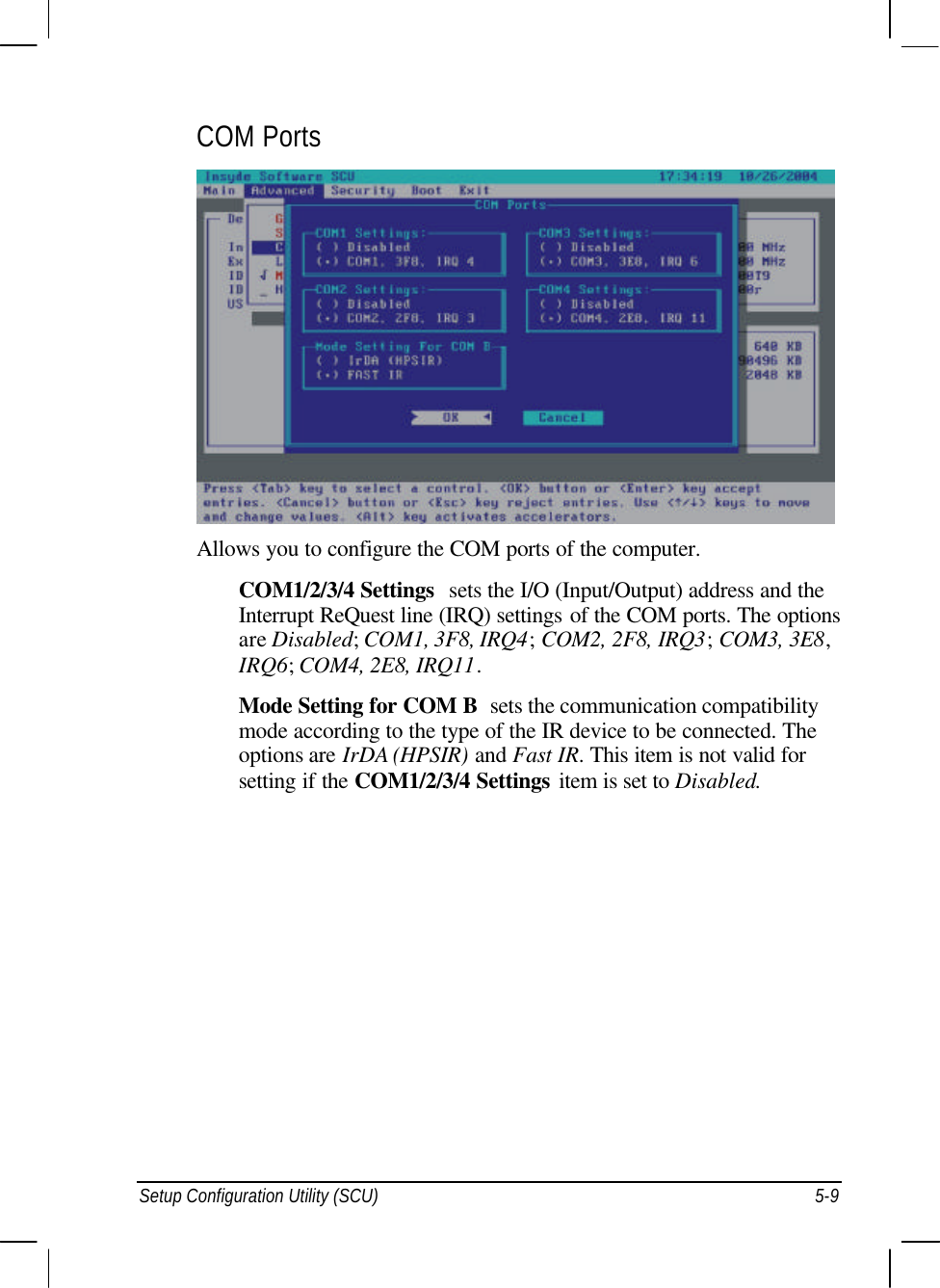
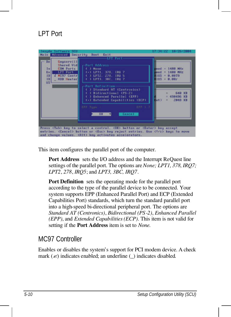
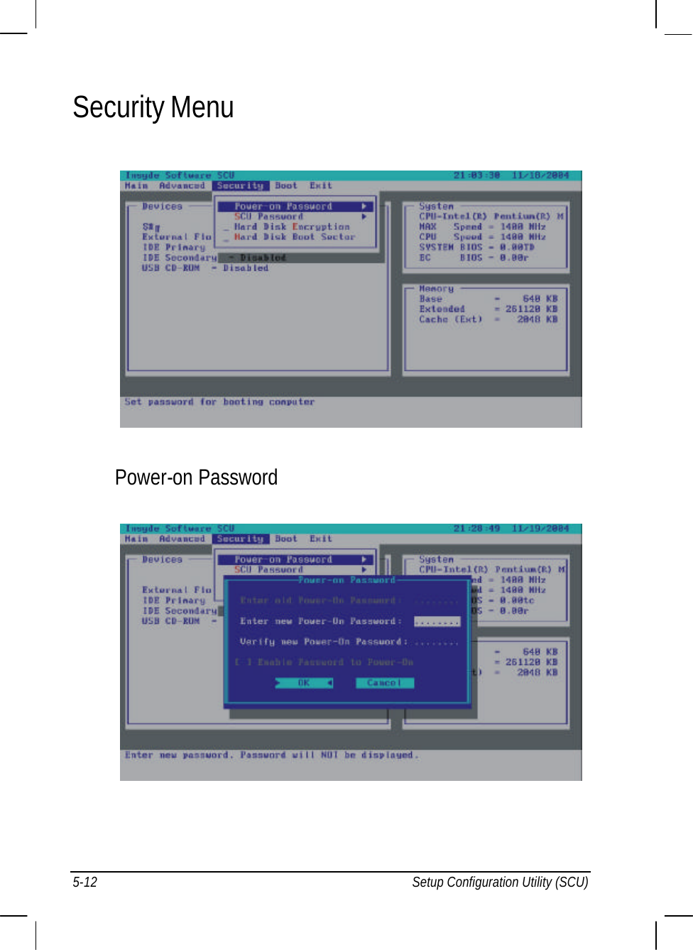
User Manual
Discussion / Help
Navigation
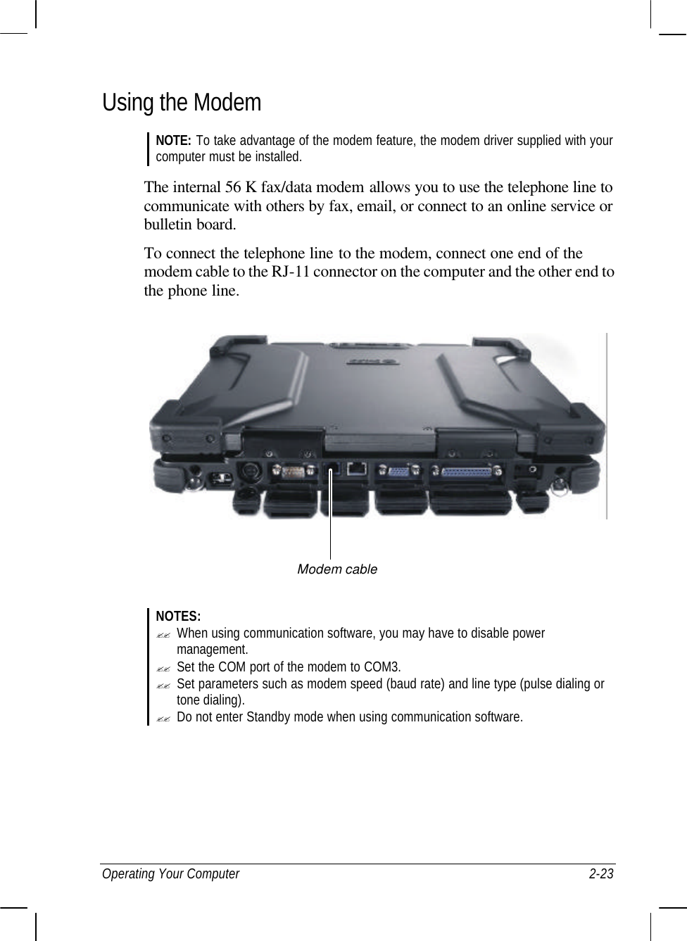


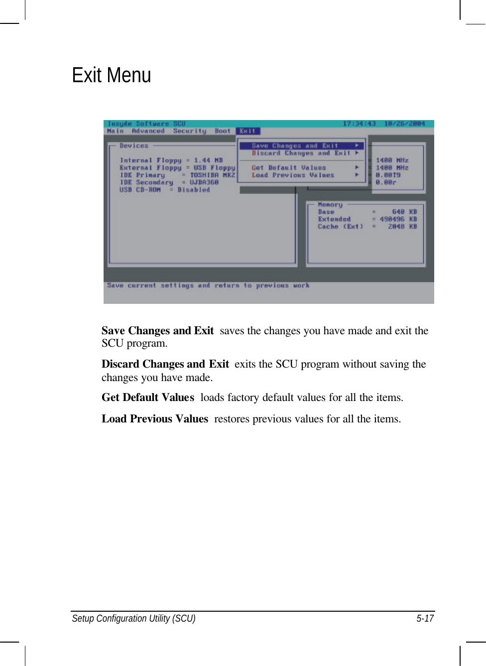
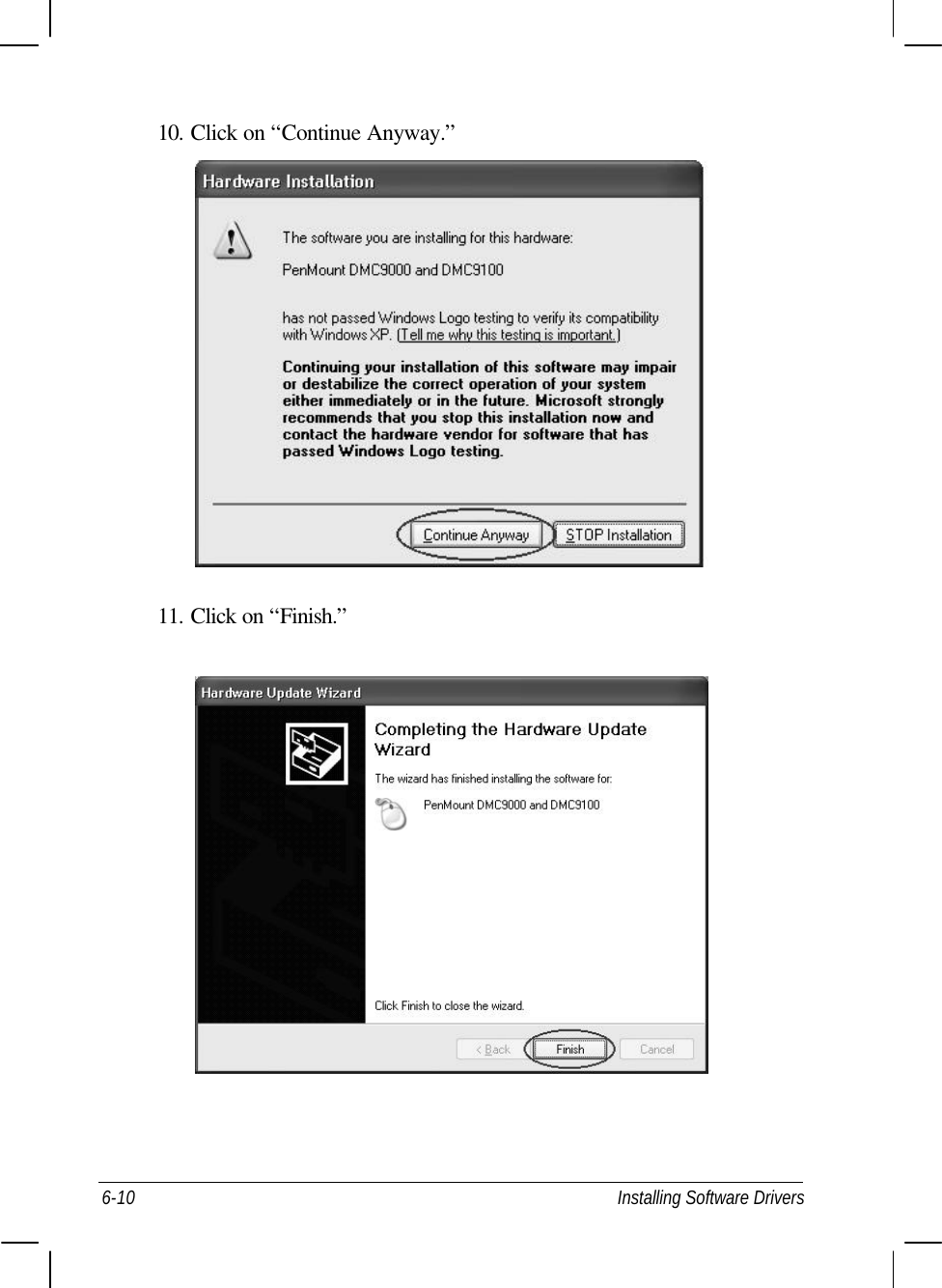
![Installing Software Drivers 6-9 8. Click on “Reinstall Driver.” 9. When the “Hardware Update Wizard” appears, select “Install the software automatically [Recommended],” then click on “Next.”](https://usermanual.wiki/Getac-Technology/012/User-Guide-510318-Page-98.png)