Getac Technology 046 Wireless LAN Module User Manual rev02
Getac Technology Corp. Wireless LAN Module rev02
User Manual (rev02)

Rugged Mobile Computing Solutions
V200
USER’S MANUAL

Aug. 2012
TRADEMARKS
TRADEMARKSTRADEMARKS
TRADEMARKS
The Bluetooth® word mark and logos are owned by the Bluetooth SIG, Inc. All brand
and product names are trademarks or registered trademarks of their respective
companies.
NOTE
NOTENOTE
NOTE
The information in this manual is subject to change without notice.
Most screens and operating instructions in this manual are based on Windows 7.
If you’re using a different version of Windows, the screens and related operations

may not be the same.
For the latest version of the manual, please visit the Getac website at www.getac.com.
ENERGY STAR® is a government program that offers businesses and consumers
energy-efficient solutions, making it easy to save money while protecting the
environment for future generations.
Please reference ENERGY STAR® related information from www.energystar.gov.
As an ENERGY STAR® Partner, Getac Technology Corporation has determined that
this product meets the ENERGY STAR® guidelines for energy efficiency.
An ENERGY STAR® qualified computer uses 70 % less electricity than computers
without enabled power management features.
Earning the
Earning the Earning the
Earning the E
EE
ENERGY
NERGY NERGY
NERGY S
SS
STAR
TARTAR
TAR®
®®
®
When every home office is powered by equipment that has earned the ENERGY
STAR®, the change will keep over 289 billion pounds of greenhouse gases out
of the air.
If left inactive, ENERGY STAR® qualified computers enter a low-power mode
and may use 15 watts or less. New chip technologies make power management
features more reliable, dependable, and user-friendly than even just a few years
ago.
Spending a large portion of time in low-power mode not only saves energy,
but helps equipment run cooler and last longer.

Businesses that use ENERGY STAR® enabled office equipment may realize
additional savings on air conditioning and maintenance.
Over its lifetime, ENERGY STAR® qualified equipment in a single home office
(e.g., computer, monitor, printer, and fax) can save enough electricity to light
an entire home for more than 4 years.
Power management (“sleep settings”) on computers and monitors can result
in much savings annually.
Remember, saving energy prevents pollution
Remember, saving energy prevents pollutionRemember, saving energy prevents pollution
Remember, saving energy prevents pollution
Because most computer equipment is left on 24 hours a day, power management
features are important for saving energy and are an easy way to reduce air pollution.
By using less energy, these products help lower consumers’ utility bills, and prevent
greenhouse gas emissions.

i
Table of Contents
Table of ContentsTable of Contents
Table of Contents
Chapter 1
Chapter 1Chapter 1
Chapter 1
G
GG
Getting Started
etting Startedetting Started
etting Started
................................
................................................................
..............................................
............................
..............
1
11
1-
--
-1
11
1
Getting the Computer Running ......................................... 1-2
Unpacking ................................................................ 1-2
Connecting to AC Power ............................................ 1-3
Opening and Closing the Cover ................................... 1-4
Operating in Tablet Mode ........................................... 1-5
Turning On and Off the Computer ............................... 1-7
Taking a Look at the Computer ...................................... 1-8
Front Components ..................................................... 1-8
Rear Components ..................................................... 1-10
Right-Side Components ............................................. 1-11
Left-Side Components ............................................... 1-12
Top-open Components .............................................. 1-13
Bottom Components .................................................. 1-15
Using the Accessories .................................................. 1-17
Using the Tether ..................................................... 1-17
Attaching the Handgrip Strap ...................................... 1-18
Attaching the Shoulder Strap ...................................... 1-18
Chapter
Chapter Chapter
Chapter 2
22
2
O
OO
Operating Your Computer
perating Your Computerperating Your Computer
perating Your Computer
.............................
..........................................................
.............................
2
22
2-
--
-1
11
1
Using the Internal Keyboard ............................................2-2
Typewriter Keys ........................................................2-2
Cursor-Control Keys ..................................................2-2

ii
Numeric Keypad .......................................................2-3
Function Keys ..........................................................2-4
Fn Key ...................................................................2-4
Hot Keys ................................................................2-4
Using the Touchpad ......................................................2-7
Configuring the Touchpad ............................................2-9
Navigating on the Screen ............................................. 2-10
Using the Touchscreen ............................................. 2-10
Using Multi-touch Gestures ........................................ 2-11
Using the Dual Mode Display (Optional) .................... 2-13
Using Landscape or Portrait View ............................... 2-15
Using the Input Panel ................................................. 2-17
Using the Network Features ........................................... 2-18
Using the Modem ................................................... 2-18
Using the LAN ....................................................... 2-19
Using the Wireless LAN ........................................... 2-19
Using the Bluetooth Feature ......................................... 2-21
Turning Off/On the Bluetooth Radio ........................... 2-21
Connecting to another Bluetooth Device ....................... 2-21
Using the WWAN Feature (Optional) ............................ 2-23
Installing a SIM Card .............................................. 2-23
Turning Off/On the WWAN Radio .............................. 2-24
Connecting to WWAN Network ................................... 2-25
Using the Fingerprint Scanner (Optional)........................ 2-27
Chapter
Chapter Chapter
Chapter 3
33
3
M
MM
Managing
anaging anaging
anaging Power
PowerPower
Power
................................
................................................................
.............................................
..........................
.............
3
33
3-
--
-1
11
1
AC Adapter .................................................................3-2
Battery Pack ................................................................3-3
Charging the Battery Pack ..........................................3-3
Initializing the Battery Pack .........................................3-4

iii
Checking the Battery Level .........................................3-4
Replacing the Battery Pack .........................................3-5
Battery Low Signals and Actions ..................................3-6
Power Management .......................................................3-8
Hibernation ...............................................................3-9
Power-Saving Tips ..................................................... 3-10
Chapter
Chapter Chapter
Chapter 4
44
4
E
EE
Expanding Your Computer
xpanding Your Computerxpanding Your Computer
xpanding Your Computer
............................
........................................................
............................
4
44
4-
--
-1
11
1
Connecting an External Monitor .......................................4-2
Connecting a Serial Device.............................................4-3
Connecting a USB Device ..............................................4-4
Connecting an IEEE 1394 Device ....................................4-5
Connecting Audio Devices ..............................................4-6
Using ExpressCards ......................................................4-7
Using PC Cards...........................................................4-9
Using Smart Cards (Optional) ...................................... 4-11
Using Storage Cards ................................................... 4-12
System Memory Upgrade.............................................. 4-13
Chapter
Chapter Chapter
Chapter 5
55
5
U
UU
Using BIOS Setup and System Recovery
sing BIOS Setup and System Recoverysing BIOS Setup and System Recovery
sing BIOS Setup and System Recovery
......
............
......
5
55
5-
--
-1
11
1
BIOS Setup .................................................................5-2
When and How to Use .............................................5-2
Information Menu ......................................................5-3
Main Menu ..............................................................5-4
Advanced Menu ........................................................5-5
Security Menu ........................................................ 5-12
Boot Menu ............................................................ 5-14
Exit Menu ............................................................. 5-15
System Recovery ........................................................ 5-17

iv
Chapter
Chapter Chapter
Chapter 6
66
6
U
UU
Using Getac Software
sing Getac Softwaresing Getac Software
sing Getac Software
................................
................................................................
....................................
........
....
6
66
6-
--
-1
11
1
Using the OSD Control Panel .........................................6-2
Quick Button Setup ...................................................6-6
Using Button Manager ...................................................6-8
Using G-Manager ....................................................... 6-10
Starting G-Manager ................................................. 6-10
System Tab ............................................................ 6-11
Battery Tab ........................................................... 6-12
ECO Tab .............................................................. 6-14
Light Sensor Tab .................................................... 6-16
Ignition Tab ........................................................... 6-18
Monitoring Tab ....................................................... 6-19
GPS Status Tab ..................................................... 6-20
Using Getac Camera ................................................... 6-22
Taking Pictures ....................................................... 6-24
Shooting Videos ...................................................... 6-26
Using View Mode ................................................... 6-27
Camera Settings ..................................................... 6-31
Chapter
Chapter Chapter
Chapter 7
77
7
C
CC
Caring for the Computer
aring for the Computeraring for the Computer
aring for the Computer
...............................
..............................................................
...............................
7
77
7-
--
-1
11
1
Protecting the Computer .................................................7-2
Using an Anti-Virus Strategy .......................................7-2
Using Action Center (for Windows 7) .........................7-2
Using the Cable Lock ................................................7-3
Taking Care of the Computer .........................................7-4
Location Guidelines ....................................................7-4
General Guidelines ....................................................7-5
Cleaning Guidelines ...................................................7-5
Battery Pack Guidelines ..............................................7-6
Touchscreen Guidelines...............................................7-7

v
When Traveling ............................................................7-9
Chapter
Chapter Chapter
Chapter 8
88
8
................................
................................................................
.................................................
..................................
.................
T
TT
Troubleshooting
roubleshootingroubleshooting
roubleshooting
8
88
8-
--
-1
11
1
Preliminary Checklist ......................................................8-2
Solving Common Problems .............................................8-3
Battery Problems .......................................................8-3
Bluetooth Problems ....................................................8-3
Display Problems ......................................................8-4
Hardware Device Problems ..........................................8-5
Hard Disk Drive Problems ..........................................8-5
Keyboard, Mouse, and Touchpad Problems ....................8-6
LAN Problems ..........................................................8-6
Modem Problems ......................................................8-7
Power Management Problems ......................................8-7
Software Problems .....................................................8-8
Sound Problems .......................................................8-8
Startup Problems .......................................................8-9
WLAN Problems .......................................................8-9
Other Problems ....................................................... 8-11
Resetting the Computer ................................................ 8-12
Appendix A S
Appendix A SAppendix A S
Appendix A Specifications
pecificationspecifications
pecifications
................................
................................................................
............................................
........................
............
A
AA
A-
--
-1
11
1
Appendix
Appendix Appendix
Appendix B R
B RB R
B Regulatory Information
egulatory Informationegulatory Information
egulatory Information
............................
........................................................
............................
B
BB
B-
--
-1
11
1
On the Use of the System ........................................... B-2
Class B Regulations ................................................. B-2
UL1604 Installation Instructions .................................... B-3
Safety Notices ......................................................... B-4
On the Use of the RF Device ...................................... B-7
USA and Canada Safety Requirements and Notices ........ B-7
European Union CE Marking and Compliance Notices ..... B-10

vi

Getting Started 1-1
Chapter 1
Chapter 1Chapter 1
Chapter 1
Getting Started
Getting StartedGetting Started
Getting Started
Congratulations on purchasing this rugged computer.
This chapter first tells you step by step how to get the computer up and running.
Then, you will find a section briefly introducing the external components of the
computer.

1-2 Getting Started
Getting the Computer Running
Getting the Computer RunningGetting the Computer Running
Getting the Computer Running
This section guides you through the procedures for getting the computer ready for
operation.
Unpacking
UnpackingUnpacking
Unpacking
After unpacking the shipping carton, you should find these standard items:
Notebook computer
Accessories:
− AC adapter
− AC power cord
− Shoulder strap
− Handgrip strap
− Stylus and tether
− Digitizer pen (option)
− Driver disc
− Documents
Inspect all the items. If any item is damaged or missing, notify your dealer immediately.
Keep the shipping carton and packing materials in case you need to ship or store
the computer in the future.
Getting Started 1-3
Connecting to AC Power
Connecting to AC PowerConnecting to AC Power
Connecting to AC Power
The computer operates either on the external AC power or internal battery power.
It is suggested that you use AC power when you start up the computer for the
very first time.
CAUTION: Use only the AC adapter included with your computer. Using other AC
adapters may damage the computer.
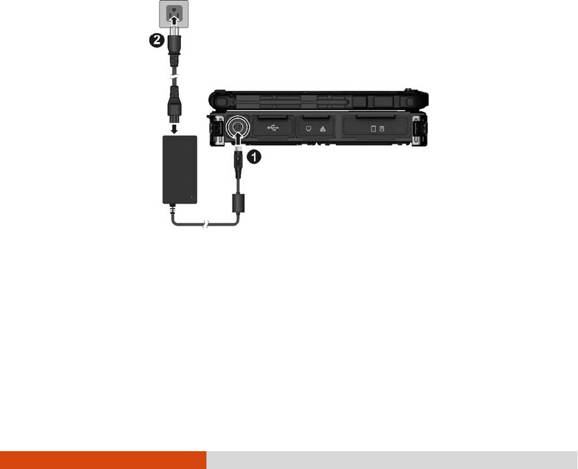
1. Plug the DC cord of the AC adapter to the power connector of the computer
().
2. Plug the female end of the AC power cord to the AC adapter and the male
end to an electrical outlet ().
3. When the AC adapter is connected, power is being supplied from the electrical
outlet to the AC adapter and onto your computer. Now, you are ready to turn
on the computer.
CAUTION:
When you disconnect the AC adapter, disconnect from the electrical outlet first
and then from the computer. A reverse procedure may damage the AC
adapter or the computer.
1-4 Getting Started
When unplugging the connector, always hold the plug head. Never pull on the
cord.
NOTE: When the AC adapter is connected, it also charges the battery pack. For
information on using battery power, see Chapter 3.
Opening and Closing the Cover
Opening and Closing the CoverOpening and Closing the Cover
Opening and Closing the Cover
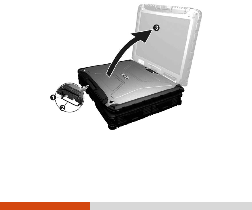
To open the top cover:
1. Pull loose the cover latch () and release the clamp ().
2. Lift up the cover (). You can tilt the cover forward or backward for optimal
viewing clarity.
To close the top cover:
1. Close the display.
Getting Started 1-5
2. Lift the cover latch and engage the clamp on the display. Then, push in the
cover latch to click it into place.
Operating in Tablet Mode
Operating in Tablet ModeOperating in Tablet Mode
Operating in Tablet Mode
In addition to being used as a regular notebook computer (Laptop mode), your
computer can also be operated in Tablet mode. In Tablet mode, you operate the
computer with a stylus or digitizer pen, or a fingertip, instead of a keyboard or mouse.
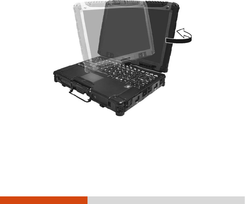
1. Open the top cover so that it is almost perpendicular with the keyboard of the
computer.
2. Turn the display counter-clockwise by 165o.
CAUTION: Do not rotate the display more than 165o, or attempt to rotate the
display clockwise.
3. Close the computer with the display facing up.
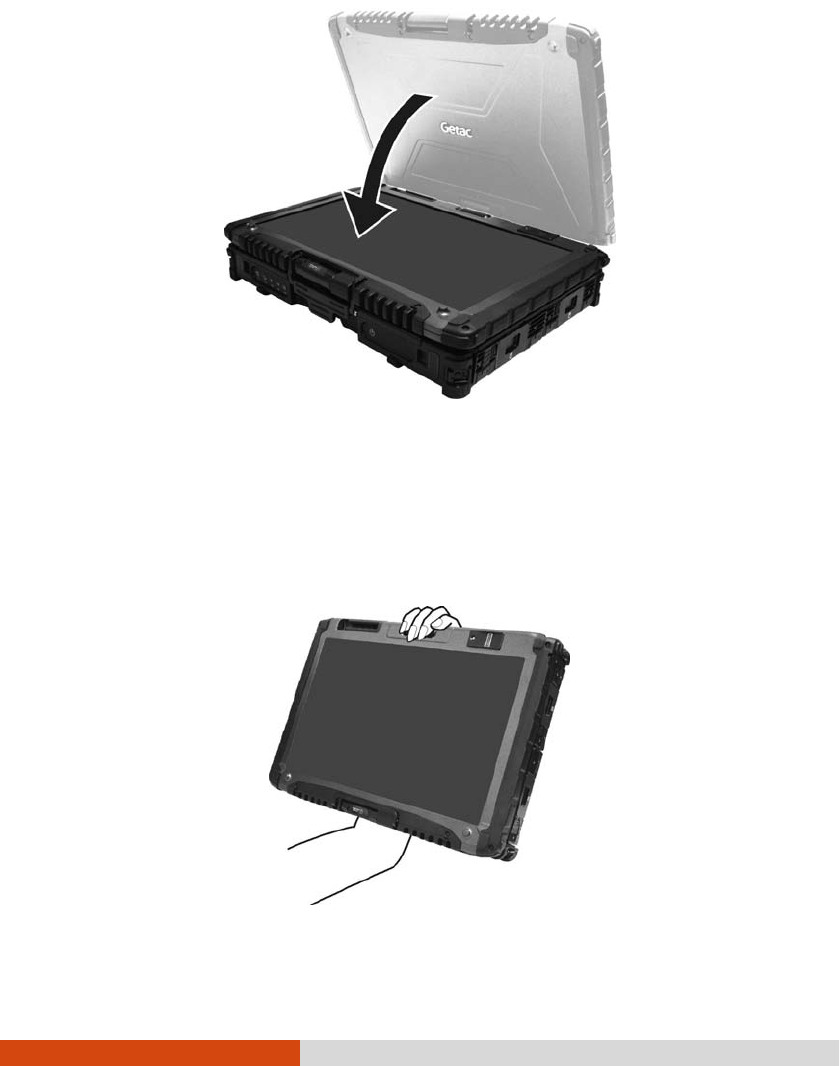
1-6 Getting Started
4. Lift the cover latch and engage the clamp on the display. Then, push in the
cover latch to click it into place.
In Tablet mode, the computer can be operated while holding it as shown. A handgrip
strap is supplied to help you hold the computer. (See “Attaching the Handgrip Strap”
in this chapter for installation instructions.)
Getting Started 1-7
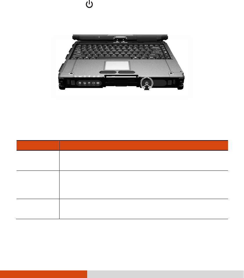
Turning On and Off the Computer
Turning On and Off the ComputerTurning On and Off the Computer
Turning On and Off the Computer
Turning On
Turning OnTurning On
Turning On
Press the power button (
). Each time the computer is turned on, it performs
a Power-On Self Test (POST), and the operating system such as Windows should
start.
Turning O
Turning OTurning O
Turning Off
ffff
ff
When you finish a working session, you can stop the system by turning off the power
or leaving it in Sleep or Hibernation mode:
To...
To...To...
To...
Do this...
Do this...Do this...
Do this...
Power off
(Shutdown)
Use the Windows Start menu in the lower left and follow the
shutdown procedure.
Sleep Press the power button*.
–or–
Use the Windows Start menu to put the computer in Sleep mode.
Hibernate
Use the Windows Start menu to put the computer in Hibernation
mode. (See “Hibernation” in Chapter 3 for more information.)
* “Sleep” is the default setting of the power button. You may change what the
power button does in Windows Control Panel.
1-8 Getting Started
Taking a Look at the Computer
Taking a Look at the ComputerTaking a Look at the Computer
Taking a Look at the Computer
NOTE:
Depending on the model you purchased, the appearance of your computer
may not be exactly the same as those shown in this manual.
You need to open the protective covers to access the connectors. When not
using a connector, make sure to close the cover completely for water- and
dust-proof integrity. (Engage the locking mechanism if existing.)
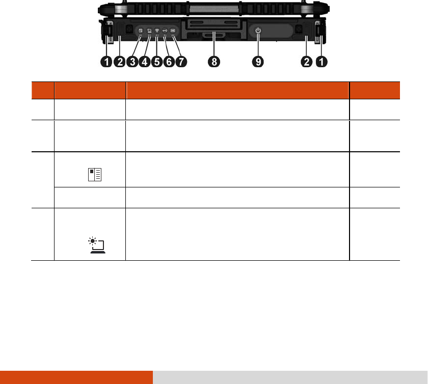
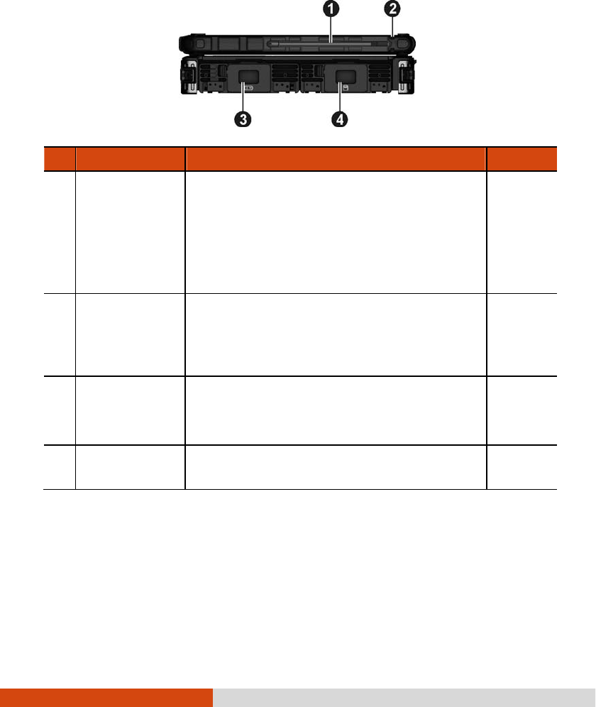
Front Components
Front ComponentsFront Components
Front Components
Ref
RefRef
Ref
Component
ComponentComponent
Component
Description
DescriptionDescription
Description
See Also
See AlsoSee Also
See Also
Strap Holder
Strap HolderStrap Holder
Strap Holder
Two buckles hold the shoulder strap. P. 1-18
Stereo
Stereo Stereo
Stereo
Speaker
SpeakerSpeaker
Speaker
Sends out sound and voice from your computer.
OSD Control
OSD Control OSD Control
OSD Control
Button
Button Button
Button
Opens or closes the OSD (On Screen Display)
control panel.
P. 6-2
P1 Button
P1 ButtonP1 Button
P1 Button
Can be re-defined using the Button Manager utility.
P. 6-8
Sunlight
SunlightSunlight
Sunlight-
--
-
rea
rearea
readable
dable dable
dable
Button
ButtonButton
Button
Toggles the sunlight-readable mode on or off.
In sunlight-
readable mode, the display brightness
is increased to the highest level.
Getting Started 1-9
Ref
RefRef
Ref
Component
ComponentComponent
Component
Description
DescriptionDescription
Description
See Also
See AlsoSee Also
See Also
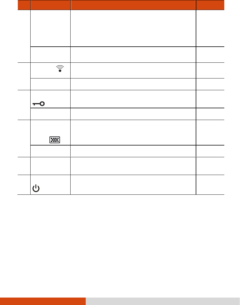
CAUTION: To prevent burns to your fingers if
using the computer (especially in Tablet Mode)
with sunlight-readable mode turned on, do wear
gloves when touching the top portion of the LCD
display as it may be hot to the touch.
P2
P2P2
P2
Button
ButtonButton
Button
Can be re-defined using the Button Manager utility.
P. 6-8
RF Button
RF Button RF Button
RF Button
Serves as the master on/off control of the RF radio.
P3
P3P3
P3
Button
ButtonButton
Button
Can be re-defined using the Button Manager utility.
P. 6-8
Reset Button
Reset Button Reset Button
Reset Button
Serves as the Ctrl
CtrlCtrl
Ctrl+Alt
AltAlt
Alt+Del
DelDel
Del keyboard keys. P. 8-12
P4
P4P4
P4
Button
ButtonButton
Button
Can be re-defined using the Button Manager utility.
P. 6-8
Software
Software Software
Software
Keyboard
Keyboard Keyboard
Keyboard
Button
Button Button
Button
Opens or closes the software keyboard on your
screen.
P. 2-17
P5
P5P5
P5
Button
ButtonButton
Button
Can be re-defined using the Button Manager utility.
P. 6-8
Top Cover
Top Cover Top Cover
Top Cover
Latch
LatchLatch
Latch
Locks the top cover. P. 1-4
Power
Power Power
Power Button
ButtonButton
Button
Turns the power on or off (Sleep mode by
default).
P. 1-7
1-10 Getting Started
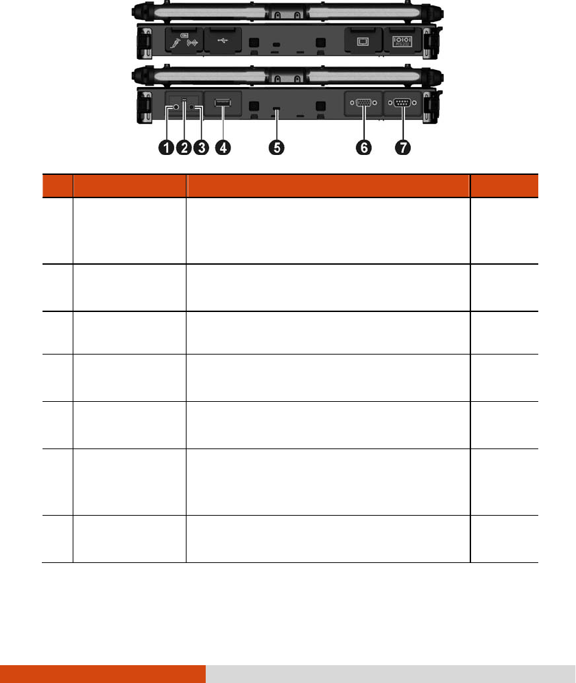
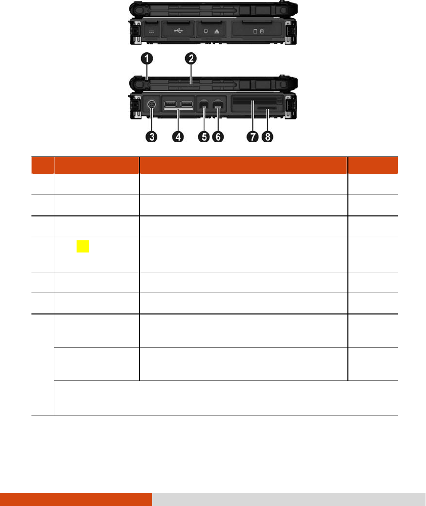
Rear Components
Rear ComponentsRear Components
Rear Components
Ref
RefRef
Ref
Component
ComponentComponent
Component
Description
DescriptionDescription
Description
See Also
See AlsoSee Also
See Also
Audio Output
Audio Output Audio Output
Audio Output
Connector
ConnectorConnector
Connector
Connects a set of headphones, external
speakers with amplifier, or
an audio recording
device.
P. 4-6
Mini IEEE 1394
Mini IEEE 1394 Mini IEEE 1394
Mini IEEE 1394
Port
PortPort
Port
Connects an IEEE 1394 device such as a
scanner, printer, DVCAM, and VCR.
P. 4-5
Microphone
Microphone Microphone
Microphone
Connector
ConnectorConnector
Connector
Connects an external microphone. P. 4-6
USB 2.0 Port
USB 2.0 PortUSB 2.0 Port
USB 2.0 Port
Connects a USB device, such as a
flash disk,
printer, digital camera, joystick, and more.
P. 4-4
Kensington Lock
Kensington LockKensington Lock
Kensington Lock
Locks the computer to a stationary object for
security.
P. 7-3
VGA Connector
VGA ConnectorVGA Connector
VGA Connector
Connects an external display monitor.
(Depending on your model, this port could be
a serial connector.)
P. 4-2
Serial Connector
Serial ConnectorSerial Connector
Serial Connector
Connects a serial mouse or serial communication
device.
P. 4-3
Getting Started 1-11
Right
RightRight
Right-
--
-Side Components
Side ComponentsSide Components
Side Components
Ref
RefRef
Ref
Component
ComponentComponent
Component
Description
DescriptionDescription
Description
See Also
See AlsoSee Also
See Also
Stylus
StylusStylus
Stylus
Serves as the input device by tapping on the
touchscreen to make selections and enter
information.
NOTE: Some models do not have the stylus
slot on this side, so you can only use the slot on
the left side for storing the stylus.
P. 2-10
Tether Hole
Tether HoleTether Hole
Tether Hole
Stylus can be tethered to this hole.
NOTE: Depending on your model, this is on
both sides of the computer or on the left side
only.
P. 1-17
Battery Pack
Battery Pack Battery Pack
Battery Pack
Compartment
Compartment Compartment
Compartment
Inside is the battery pack that supplies power to
your computer when external power is not
connected.
P. 3-3
Hard Disk Drive
Hard Disk Drive Hard Disk Drive
Hard Disk Drive
Compartment
Compartment Compartment
Compartment
Inside is the hard disk drive.
1-12 Getting Started
Left
LeftLeft
Left-
--
-Side Components
Side ComponentsSide Components
Side Components
Ref
RefRef
Ref
Component
ComponentComponent
Component
Description
DescriptionDescription
Description
See Also
See AlsoSee Also
See Also
Tether Hole
Tether HoleTether Hole
Tether Hole
Stylus can be tethered to this hole. P. 1-17
Stylus Slot
Stylus SlotStylus Slot
Stylus Slot
Stylus can be stored in this slot.
Power Connector
Power ConnectorPower Connector
Power Connector
Connects the AC adapter. P. 1-3
USB
USB USB
USB 3.0
3.03.0
3.0
Port
PortPort
Port
Connects a USB dev
ice, such as a flash disk,
printer, digital camera, joystick, and more.
P. 4-4
RJ
RJRJ
RJ-
--
-11
1111
11
Connector
ConnectorConnector
Connector
Connects the telephone line. P. 2-18
RJ
RJRJ
RJ-
--
-45
4545
45
Connector
ConnectorConnector
Connector
Connects the LAN cable. P. 2-19
ExpressCard Slot
ExpressCard Slot ExpressCard Slot
ExpressCard Slot
(upper)
Accepts an ExpressCard for additional functions.
P. 4-7
PC
PCPC
PC
Card
Card Card
Card Slot
SlotSlot
Slot
(lower)
Accepts a PC card for additional functions. P. 4-9
Depending on your model, the two slots could be a different combination (as
below).
Getting Started 1-13
Smart Card
Smart Card Smart Card
Smart Card
Reader
Reader Reader
Reader (upper)
Accepts a smart card for additional security
feature.
P. 4-11
Ref
RefRef
Ref
Component
ComponentComponent
Component
Description
DescriptionDescription
Description
See Also
See AlsoSee Also
See Also
ExpressCard Slot
ExpressCard Slot ExpressCard Slot
ExpressCard Slot
(lower)
Accepts an ExpressCard for additional functions.
P. 4-7
SD Card Reader
SD Card ReaderSD Card Reader
SD Card Reader
Accepts a SD/SDHC/SDXC
card for removable
storage media.
P. 4-12
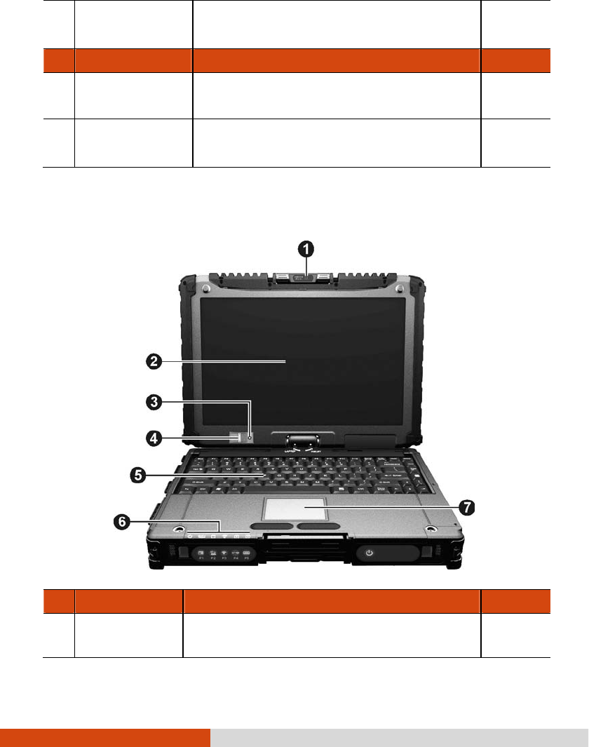
Top
TopTop
Top-
--
-open Components
open Componentsopen Components
open Components
Ref
RefRef
Ref
Com
ComCom
Component
ponentponent
ponent
Description
DescriptionDescription
Description
See Also
See AlsoSee Also
See Also
Camera Lens
Camera LensCamera Lens
Camera Lens
Allows you to use your computer’s camera
function.
The lens supports 2 MP (mega pixel).
P. 6-22
1-14 Getting Started
Ref
RefRef
Ref
Com
ComCom
Component
ponentponent
ponent
Description
DescriptionDescription
Description
See Also
See AlsoSee Also
See Also
It can be rotated.
Touchscreen
TouchscreenTouchscreen
Touchscreen
Displays and receives information for the
computer.
P. 2-10
Light Sensor
Light SensorLight Sensor
Light Sensor
Detects the surrounding lighting condition for
automatic adjustment of the LCD brightness and
optional keyboard backlight.
Fingerprint
Fingerprint Fingerprint
Fingerprint
Scanner
Scanner Scanner
Scanner
(optional)
Uses fingerprint verification to protect your
computer against unauthorized access.
P. 2-27
Keyboard
KeyboardKeyboard
Keyboard
Serves as the data input device. P. 2-2
Touchpad
TouchpadTouchpad
Touchpad
Serves as the pointing device. P. 2-7
Indicators
IndicatorsIndicators
Indicators
Show the current status of the computer’s
devices.
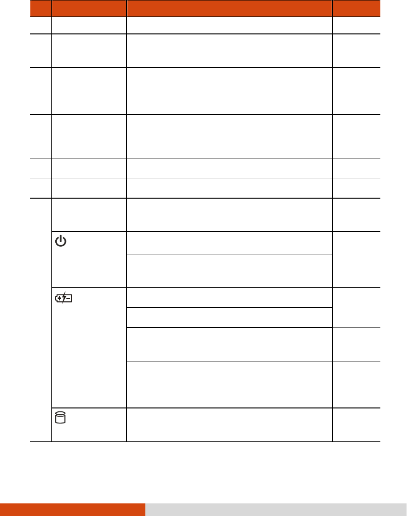
Power
PowerPower
Power
Lights green when the computer is turned on.
P. 1-7
Lights yellow when the computer is in Sleep
mode.
Battery
Battery Battery
Battery
Charge
ChargeCharge
Charge
Lights green when the battery is fully charged.
P. 3-3
Lights yellow when the battery is being charged.
Blinks yellow when the battery’s capacity is below
10%.
P. 3-6
Blinks green and yellow by turns to indicate
charging is suspended because the battery’s
temperature is either too high or too low.
Hard Disk
Hard Disk Hard Disk
Hard Disk
Drive In
Drive InDrive In
Drive In-
--
-Use
UseUse
Use
Lights green when the computer is accessing the
hard disk drive.
Getting Started 1-15
Ref
RefRef
Ref
Com
ComCom
Component
ponentponent
ponent
Description
DescriptionDescription
Description
See Also
See AlsoSee Also
See Also
Blinks red w
hen the optional hard disk drive heater
is on for low temperature operation.
P. 8-9
RF
RFRF
RF Lights when the radio frequency is on.
Num Lock
Num LockNum Lock
Num Lock Lights when Num Lock is on. P. 2-3
Caps Lock
Caps LockCaps Lock
Caps Lock
Lights when Caps Lock is on. P. 2-2
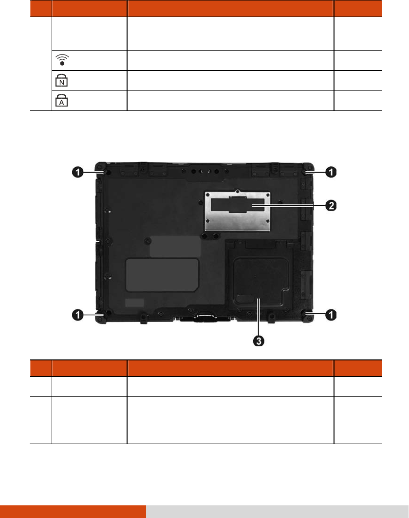
Bottom Components
Bottom ComponentsBottom Components
Bottom Components
Ref
RefRef
Ref
Component
ComponentComponent
Component
Description
DescriptionDescription
Description
See Also
See AlsoSee Also
See Also
Strap Holder
Strap HolderStrap Holder
Strap Holder
Four bottom hooks hold the handgrip strap. P. 1-18
Docking
Docking Docking
Docking
Connector
ConnectorConnector
Connector
Inside is the docking connector for connecting an
office dock or vehicle dock (purchased
separately).

1-16 Getting Started
Memory Slots
Memory SlotsMemory Slots
Memory Slots
Inside are the memory slots for expanding the
memory size of your computer.
P. 4-13
SIM Card Slot
SIM Card Slot SIM Card Slot
SIM Card Slot
(optional)
Inside is the SIM card slot. P. 2-23

Getting Started 1-17
Using the Accessories
Using the AccessoriesUsing the Accessories
Using the Accessories
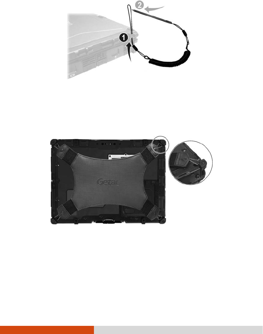
Using the Tether
Using the TetherUsing the Tether
Using the Tether
A tether is provided for attaching the stylus to your computer.
1. Insert one of the tether’s loop ends through the hole of the stylus (as indicated
by below). Then, insert the other end through the first loop (as indicated
by below) and pull it tight.
2. Insert the other loop end to the tether hole on the computer (as indicated by
below). Then, insert the stylus end through the loop (as indicated by
below) and pull it tight.
1-18 Getting Started
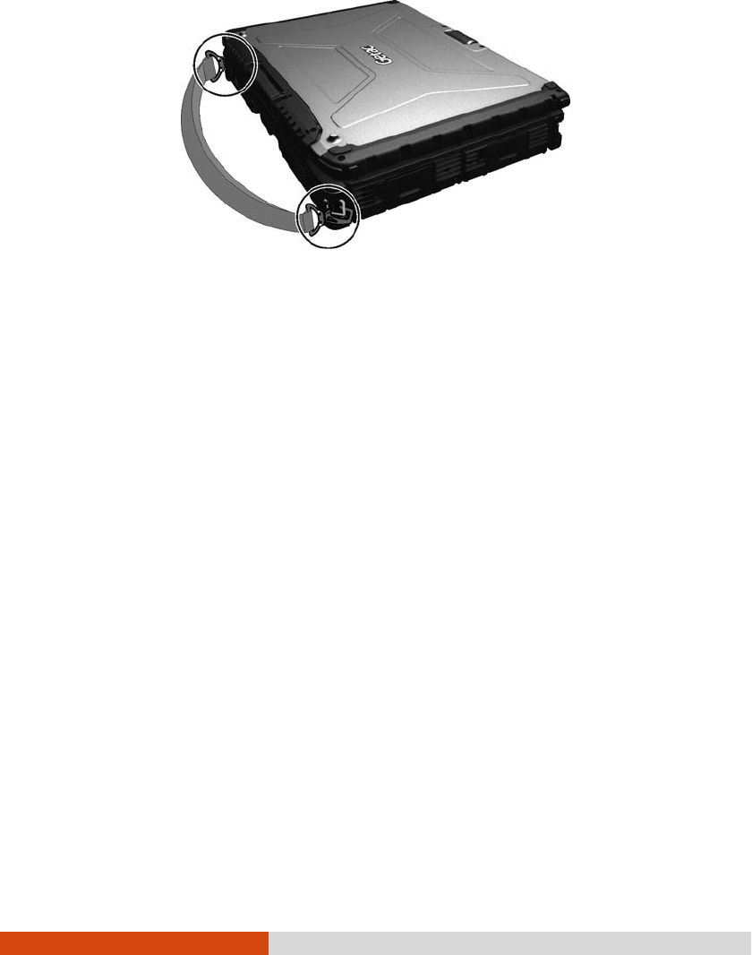
Attaching the Handgrip Strap
Attaching the Handgrip StrapAttaching the Handgrip Strap
Attaching the Handgrip Strap
To use the handgrip strap, attach its four loops to the four bottom hooks on your
computer. Make sure the loops are securely hooked.
When you need to operate and hold your computer at the same time, insert your
hand through the strap for a firm grip.
Attaching the Shoulder Strap
Attaching the Shoulder StrapAttaching the Shoulder Strap
Attaching the Shoulder Strap
To use the shoulder strap, secure the snap hooks to
the two buckles on your computer.
(Select models have four buckles for different positioning of the strap.)
Getting Started 1-19
CAUTION:
The strap has been designed to carry only the weight of the computer.
Therefore, be sure that the strap does not carry a weight that exceeds the
weight of the computer. The strap may accidentally come loose from the
computer.
Do not use a strap that is damaged or about to tear.

Operating Your Computer 2-1
Chapter 2
Chapter 2Chapter 2
Chapter 2
Operating Your Computer
Operating Your ComputerOperating Your Computer
Operating Your Computer
This chapter provides information about the use of the computer.
If you are new to computers, reading this chapter will help you learn the operating
basics. If you are already a computer user, you may choose to read only the parts
containing information unique to your computer.
CAUTION:
Do not expose your skin to the computer when operating it in a very hot or cold
environment.
The computer can get uncomfortably warm when you use it in high
temperatures. As a safety precaution in such a circumstance, do not place the
computer on your lap or touch it with your bare hands for extended periods of
time. Prolonged body contact can cause discomfort and potentially a burn.

2-2 Operating Your Computer
Using the Internal Keyboard
Using the Internal KeyboardUsing the Internal Keyboard
Using the Internal Keyboard
Your keyboard has all the standard functions of a full-sized computer keyboard plus
an Fn
FnFn
Fn key added for specific functions.
The standard functions of the keyboard can be further divided into four major categories:
Typewriter keys
Cursor-control keys
Numeric keys
Function keys
Typewriter Keys
Typewriter KeysTypewriter Keys
Typewriter Keys
Typewriter keys are similar to the keys on a typewriter. Several keys are added
such as the Ctrl
CtrlCtrl
Ctrl, Alt
AltAlt
Alt, Esc
EscEsc
Esc, and lock keys for special purposes. When the lock keys
(Caps Lock
aps Lockaps Lock
aps Lock and Num Lk
Num LkNum Lk
Num Lk) are pressed, their corresponding indicators light up.
The Control (Ctrl
CtrlCtrl
Ctrl) / Alternate (Alt
AltAlt
Alt) key is normally used in combination with other
keys for program-specific functions. The Escape (Esc
EscEsc
Esc) key is usually used for
stopping a process. Examples are exiting a program and canceling a command. The
function depends on the program you are using.
Cursor
CursorCursor
Cursor-
--
-Control Keys
Control KeysControl Keys
Control Keys
Cursor-control keys are generally used for moving and editing purposes.
NOTE: The word “cursor” refers to the indicator on the screen that lets you know
exactly where on your screen anything you type will appear. It can take the form of
a vertical or horizontal line, a block, or one of many other shapes.
Operating Your Computer 2-3
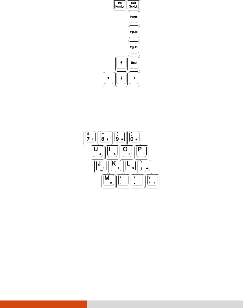
Numeric Keypad
Numeric KeypadNumeric Keypad
Numeric Keypad
A 15-key numeric keypad is embedded in the typewriter keys as shown next:
Numeric keys facilitate entering of numbers and calculations. When Num Lock is on,
the numeric keys are activated; meaning you can use these keys to enter numerals.
NOTE:
When the numeric keypad is activated and you need to type the English letter
in the keypad area, you can turn Num Lock off or you can press Fn
FnFn
Fn and then
the letter without turning Num Lock off.
Some software may not be able to use the numeric keypad on the computer. If
so, use the numeric keypad on an external keyboard instead.
2-4 Operating Your Computer
Function Keys
Function KeysFunction Keys
Function Keys
On the top row of the keys are the function keys: F1 to F12. Function keys are
multi-purpose keys that perform functions defined by individual programs.
Fn Key
Fn KeyFn Key
Fn Key
The Fn key, at the lower left corner of the keyboard, is used with another key
to perform the alternative function of a key. The letter “Fn” and the alternative functions
are identified by the color of blue on the keytop. To perform a desired function,
first press and hold Fn, then press the other key.
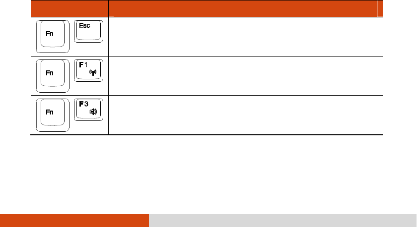
Hot Keys
Hot KeysHot Keys
Hot Keys
Hot keys refer to a combination of keys that can be pressed any time to activate
special functions of the computer. Most hot keys operate in a cyclic way. Each time
a hot key combination is pressed, it shifts the corresponding function to the other
or next choice.
You can easily identify the hot keys with the icons imprinted on the keytop. The
hot keys are described next.
Key
KeyKey
Key
Description
DescriptionDescription
Description
Switches the keyboard backlight on and off (optional).
Switches the wireless radio on and off.
Decreases the sound volume.
Operating Your Computer 2-5
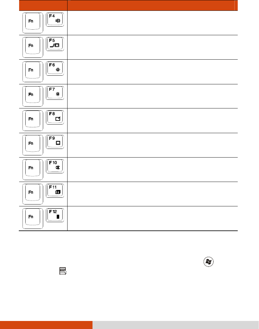
Key
KeyKey
Key
Description
DescriptionDescription
Description
Increases the sound volume.
Switches the display output when external devices are
connected.
Decreases the LCD brightness (20 levels).
Increases the LCD brightness (20 levels).
Switches the touchscreen on and off (option).
Switches the touchpad on and off.
Switches the system sound output off (mute) and on.
Switches LCD backlight on and off.
Serves as the sleep button
that you can define with Windows’
Power Options
Power OptionsPower Options
Power Options. (See the “Power Management” in Chapter 3.)
Windows Keys
Windows KeysWindows Keys
Windows Keys
The keyboard has two keys that perform Windows-specific functions: Windows
Logo key and Application key.

2-6 Operating Your Computer
The Windows Logo key opens the Start
StartStart
Start menu and performs software-specific
functions when used in combination with other keys. The Application key usually
has the same effect as a right mouse click. (See your Windows manual for more
information.)
Operating Your Computer 2-7
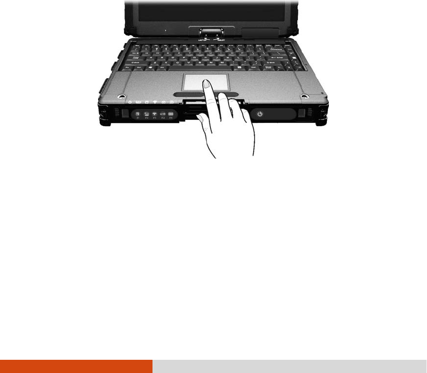
Using the Touchpad
Using the TouchpadUsing the Touchpad
Using the Touchpad
CAUTION: Do not use a sharp object such as a pen on the touchpad. Doing so
may damage the touchpad surface.
NOTE: For optimal performance of the touchpad, keep your fingers and the pads
clean and dry. When tapping on the pad, tap lightly. Do not use excessive force.
The touchpad is a pointing device that allows you to communicate with the computer
by controlling the location of the pointer on the screen and making selection with
the buttons.
The touchpad consists of a rectangular pad (work surface) and a left and right
buttons. To use the touchpad, place your forefinger or thumb on the pad. The
rectangular pad acts like a miniature duplicate of your display. As you slide your
fingertip across the pad, the pointer (also called cursor) on the screen moves
accordingly. When your finger reaches
the edge of the pad, simply relocate yourself by lifting the finger and placing it
on the other side of the pad.
Here are some common terms that you should know when using the touchpad:

2-8 Operating Your Computer
Term
TermTerm
Term
Action
ActionAction
Action
Point Move your finger on the pad until the cursor points to the selection
on the screen.
Click Press and release the left button.
–or–
Tap gently anywhere on the pad.
Double-click Press and release the left button twice in quick succession.
–or–
Tap twice on the pad rapidly.
Drag and drop
Press and hold the left button, then move your finger until you
reach your destination (drag). Finally, release the button (drop)
when you finish dragging your selection to the destination. The
object will drop into the new location.
–or–
Gently tap twice on the pad and on the second tap, keep your
finger in contact with the pad. Then, move your finger across
the pad to drag the selected object to your destination. When
you lift your finger from the pad, the selected object will drop
into place.
Scroll To scroll is to move up and down or left and right in the working
area on the screen.
To move vertically, place your finger on the right or left edge
of the pad and slide your finger up and down along the edge.
To move horizontally, place your finger on the top or bottom edge
of the pad and slide your finger left and right.
This function works only after you install the touchpad driver
supplied with the computer and it may not work for all applications.
TABLE NOTE:
TABLE NOTE:TABLE NOTE:
TABLE NOTE: If you swap the left and right buttons, “tapping” on the touchpad
as
an alternative method of pressing the left button will no longer be valid.

Operating Your Computer 2-9
Configuring the Touchpad
Configuring the TouchpadConfiguring the Touchpad
Configuring the Touchpad
You may want to configure the touchpad to suit your needs. For example, if you
are a left-handed user, you can swap the two buttons so that you can use the
right button as the left button and vice versa. You can also change the size of
the on-screen pointer, the speed of the pointer, and so on.
To configure the touchpad, go to Control Panel
Control PanelControl Panel
Control Panel Mouse Properties
Mouse PropertiesMouse Properties
Mouse Properties.

2-10 Operating Your Computer
Navigating on the Screen
Navigating on the ScreenNavigating on the Screen
Navigating on the Screen
The screen of your computer is touch-sensitive. You can control the location of the
cursor/pointer on the screen using your finger or the included stylus or digitizer pen
to communicate with the computer.
CAUTION: Do not use sharp objects on the LCD display. Doing so may damage
the display surface. Use your finger or the included stylus or digitizer pen.
Using the Touchscreen
Using the TouchscreenUsing the Touchscreen
Using the Touchscreen
If your computer is equipped with the touchscreen feature, you can use your finger
or the included stylus to navigate and select objects on the screen.
The following table shows how you use the touchscreen to obtain equivalent mouse
functions.
Term/Action
Term/ActionTerm/Action
Term/Action
Equivalent Mouse
Equivalent Mouse Equivalent Mouse
Equivalent Mouse
Function
FunctionFunction
Function
Tap: Touch the screen once. Click/Point
Double-tap: Touch the screen twice rapidly. Double-click
Operating Your Computer 2-11
Term/Action
Term/ActionTerm/Action
Term/Action
Equivalent Mouse
Equivalent Mouse Equivalent Mouse
Equivalent Mouse
Function
FunctionFunction
Function
Tap and hold: Tap and hold until a popup menu appears. Right-click
Drag: Hold the stylus (or finger) on the screen and drag
across the screen until reaching your destination.
Drag
Using Multi
Using MultiUsing Multi
Using Multi-
--
-touch Gestures
touch Gesturestouch Gestures
touch Gestures
If your computer model comes with multi-touch-capable screen and Windows 7, you
can interact with your computer by placing two fingers on the screen. The movement
of the fingers across the screen creates “gestures,” which send commands to the
computer.
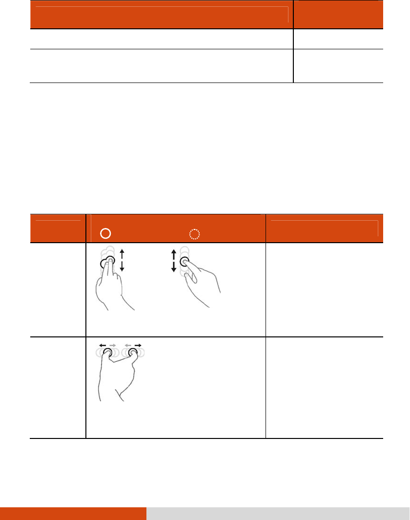
Here are the multi-touch gestures that you can use:
Gestures
GesturesGestures
Gestures
Actions
ActionsActions
Actions
( = finger down; = finger up)
( = finger down; = finger up)( = finger down; = finger up)
( = finger down; = finger up)
Descriptions
DescriptionsDescriptions
Descriptions
Pan
(Scroll)
or
Drag 1 or 2 fingers up or down.
Use panning to see
another part of a page
that has scroll bars.
Zoom
(Pinch)
Move two fingers apart/toward each
other.
Use zooming to make an
item (a photo for
example) on the screen
larger or smaller. The
gesture works in
applications that support
mouse wheel zooming.
2-12 Operating Your Computer
Gestures
GesturesGestures
Gestures
Actions
ActionsActions
Actions
( = finger down; = finger up)
( = finger down; = finger up)( = finger down; = finger up)
( = finger down; = finger up)
Descriptions
DescriptionsDescriptions
Descriptions
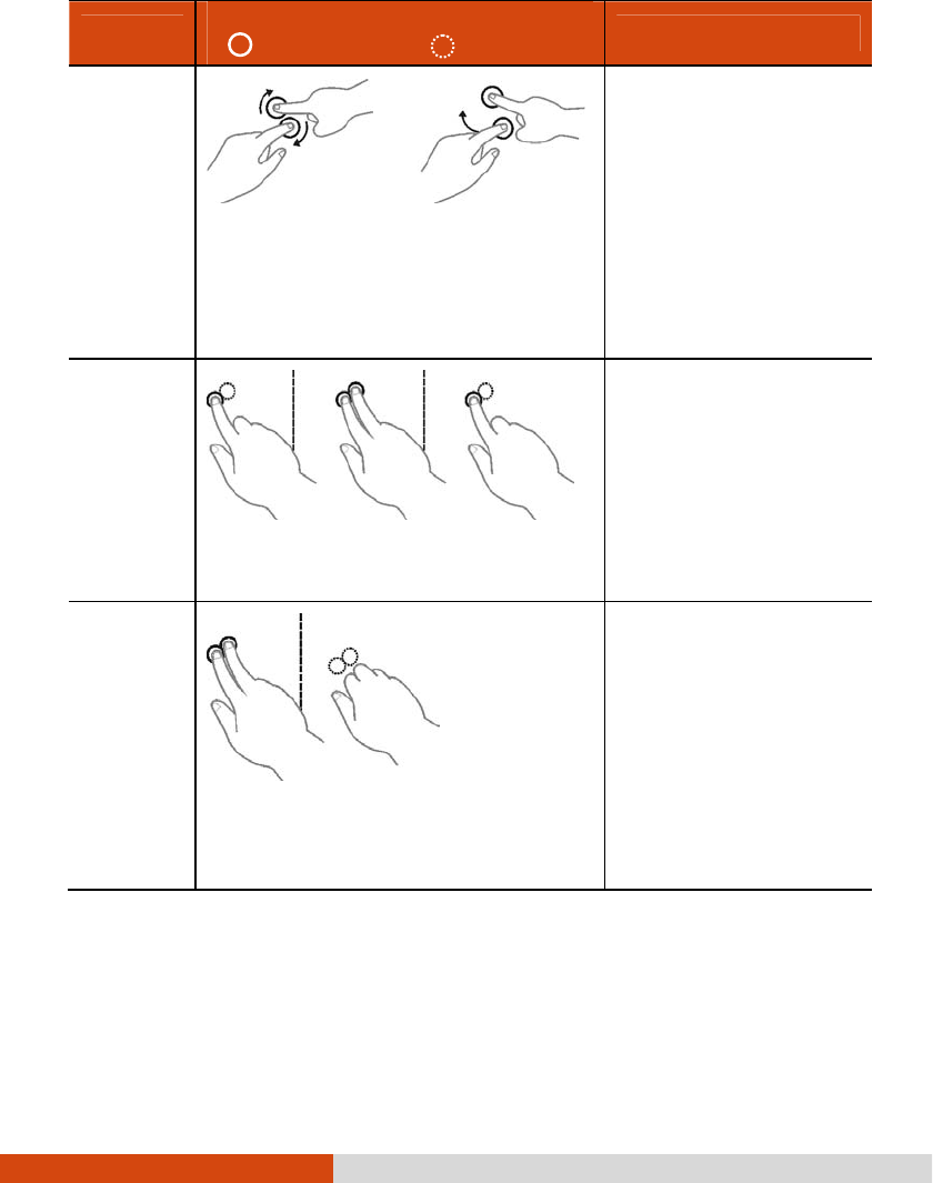
Rotate
or
Move two fingers in opposing directions.
-or-
Use one finger to pivot around another.
Use rotating to move a
picture or other item on
the screen in a circular
direction (clockwise or
counter-
clockwise). The gesture
works in applications that
support the specific
gesture.
Press and
Tap
Press on target and tap using a second
finger.
Use press and tap to
access the shortcut
menu.
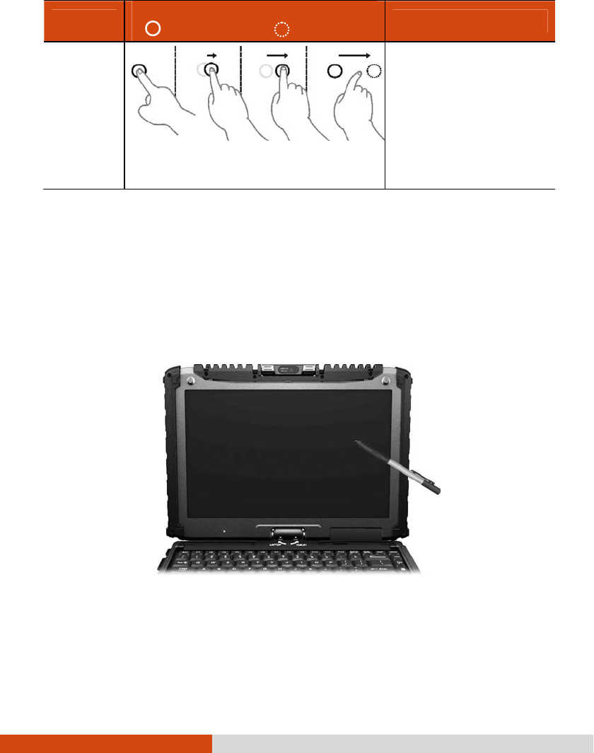
Two-
finger Tap
Tap two fingers at the same time (where
the target is in the midpoint between the
fingers).
The function is defined by
applications that support
the specific gesture.
Operating Your Computer 2-13
Gestures
GesturesGestures
Gestures
Actions
ActionsActions
Actions
( = finger down; = finger up)
( = finger down; = finger up)( = finger down; = finger up)
( = finger down; = finger up)
Descriptions
DescriptionsDescriptions
Descriptions
Flicks
Make quick drag gestures in the desired
direction.
Flick left or right to
navigate back and
forward in a browser and
other applications. The
gesture works in most
applications that support
back and forward.
Using the Dual Mode Display (Optional)
Using the Dual Mode Display (Optional)Using the Dual Mode Display (Optional)
Using the Dual Mode Display (Optional)
Dual mode display incorporates both touchscreen and digitizer functions.
The display is set to Touchscreen mode by default. Touchscreen mode provides all
the functionalities that an ordinary touchscreen has. When the computer receives signals
from the digitizer pen, the display automatically switches to Digitizer mode.
Here are some common terms that you should know when using the digitizer feature:
2-14 Operating Your Computer
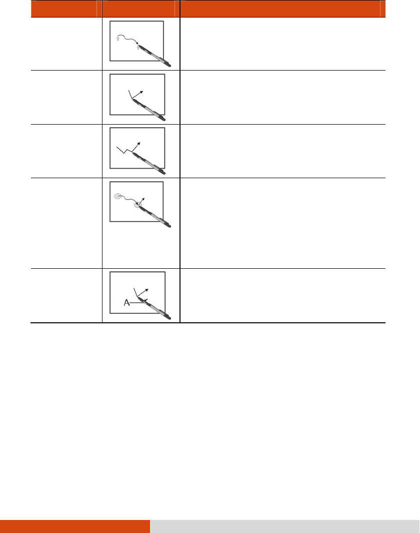
Term
TermTerm
Term
Action
ActionAction
Action
Move
Move the cursor pointed by the digitizer pen.
Click/Point
Tap gently on the display.
Double-click
Tap twice on the display rapidly.
Drag and
drop
Tap lightly on the display and move your
digitizer pen until you reach your destination
(drag). Finally, release your digitizer pen
(drop) when you finish dragging your
selection to the destination. The object will
drop into the new location.
Right-click
Press and hold down the digitizer pen button
(A), then tap gently the object.
CAUTION:
When the LCD display is used alone or with an external display
simultaneously, the digitizer function cannot be used when the area of either
display is set larger than the default setting of the display resolution.
Even when only an external display is in use, the cursor will move on the
external display if you touch the surface of the LCD display with the pen or
bring the pen close to the surface of the LCD display when the digitizer driver is
active. Therefore, do not touch the LCD display when only an external display
is in use.
The active digitizer feature cannot be used in the BIOS Setup program or
when using the full screen in DOS mode.
Operating Your Computer 2-15
NOTE:
You can move the cursor by bringing the digitizer pen close to the screen,
without actually touching the screen’s surface.
Do not move the digitizer pen too quickly. If the pen moves too quickly, the
cursor may be unable to follow its movement.
If you cannot click on the edge of the screen, hold the digitizer pen
perpendicular to the display and try clicking again.
Using Landscape or Portrait View
Using Landscape or Portrait ViewUsing Landscape or Portrait View
Using Landscape or Portrait View
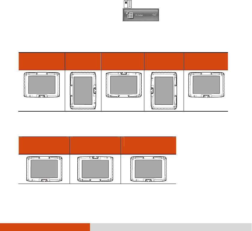
To rotate the display, press the button
located on the front of your computer
to open the OSD Control Panel and click . Each time this Rotate button
is clicked, the screen display rotates counter-clockwise by 90O.
For a Model without WWAN Module
For a Model without WWAN ModuleFor a Model without WWAN Module
For a Model without WWAN Module
Primary
Primary Primary
Primary
Landscape
LandscapeLandscape
Landscape
Primary
Primary Primary
Primary
Portrait
PortraitPortrait
Portrait
Secondary
Secondary Secondary
Secondary
Landscape
LandscapeLandscape
Landscape
Secondary
Secondary Secondary
Secondary
Portrait
PortraitPortrait
Portrait
Primary
Primary Primary
Primary
Landscape
LandscapeLandscape
Landscape
For a Model with WWAN Module
For a Model with WWAN ModuleFor a Model with WWAN Module
For a Model with WWAN Module
Primary
Primary Primary
Primary
La
LaLa
Landscape
ndscapendscape
ndscape
Secondary
Secondary Secondary
Secondary
Landscape
LandscapeLandscape
Landscape
Primary Landscape
Primary LandscapePrimary Landscape
Primary Landscape
Display
Display
Display
Display
Display
Display
Display
Display

2-16 Operating Your Computer
NOTE:
If the screen display resolution has been set to 800×600 pixels, you can rotate
the display to Primary Landscape and Secondary Landscape only.
While the display is rotated:
– Do not set the display resolution larger than the resolution of the LCD
display.
– If you exit Windows, the next time Windows is started up, the operation
of the touchpad will not match the display angle for a few seconds.
– The computer’s performance will decrease slightly.
– If a video is played, the picture may not be displayed properly or the
sound may be broken up. This problem can be corrected by rotating
the display to Primary Landscape.
– The touchpad’s scroll function does not work.
The display cannot be rotated when DOS mode is set to “Full Screen.”
Operating Your Computer 2-17
Using the Input Panel
Using the Input PanelUsing the Input Panel
Using the Input Panel
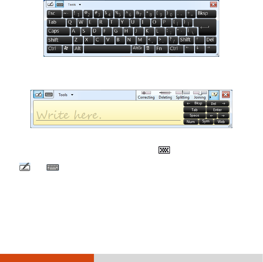
Use the Input Panel to enter text and perform various keyboard functions. There
are two types of Input Panels for you to use in Windows 7:
Touch Keyboard
Touch KeyboardTouch Keyboard
Touch Keyboard allows you to enter text by tapping the keys with your stylus,
like pressing the keys on a standard keyboard.
Writing Pad
Writing PadWriting Pad
Writing Pad allows you to write on the writing pad, like writing on a piece of
paper. Your handwriting will be converted into typed text.
To open the Input Panel, tap the Input Panel tab, which appears by default on the
left edge of the screen. (You can also press the button on the front of the
computer to open or close the Input Panel.) To switch between the two types, tap
or at the upper left corner of the Input Panel.
NOTE: For more information on using the Input Panel, see Windows’ online help.
2-18 Operating Your Computer
Using the Network Features
Using the Network FeaturesUsing the Network Features
Using the Network Features
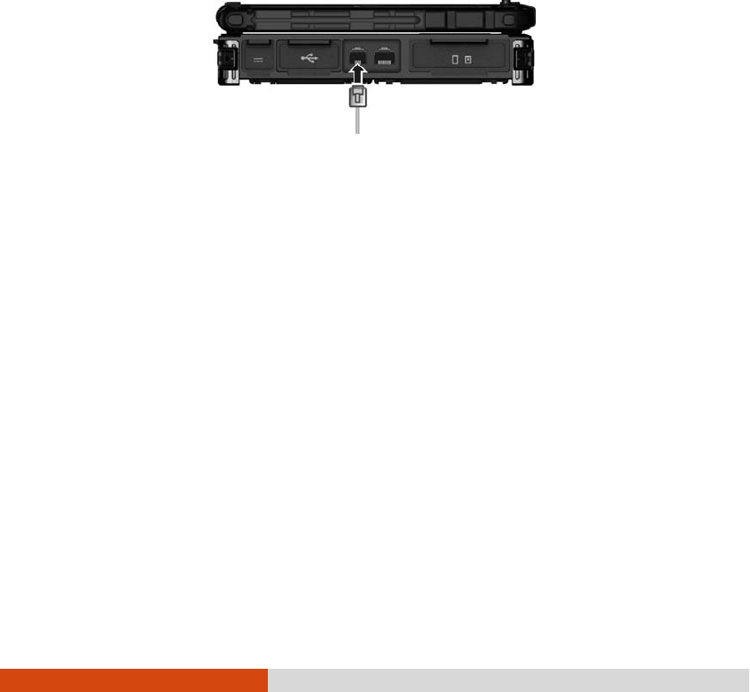
Using the Modem
Using the ModemUsing the Modem
Using the Modem
The internal 56 K fax/data modem allows you to use the telephone line to communicate
with others by fax, email, or connect to an online service or bulletin board.
To connect the telephone line to the modem, connect one end of the modem cable
to the RJ-11 connector on the computer and the other end to the phone line.
NOTE:
When using the communication software, you may have to disable power
management. Do not enter the Sleep mode when using the communication
software.
Set parameters such as modem speed (baud rate) and line type (pulse dialing
or tone dialing).
Operating Your Computer 2-19
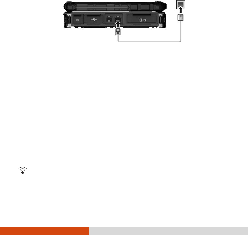
Using the LAN
Using the LANUsing the LAN
Using the LAN
The internal 10/100/1000Base-T LAN (Local Area Network) module allows you
to connect your computer to a network. It supports data transfer rate up to 1000
Mbps.
To connect the network cable to the LAN module, connect one end of the LAN
cable to the RJ-45 connector on the computer and the other end to the network
hub.
Using the Wireless LAN
Using the Wireless LANUsing the Wireless LAN
Using the Wireless LAN
The WLAN module of your computer supports IEEE 802.11a/g/n.
Turning On/Off the WLAN Radio
Turning On/Off the WLAN Radio Turning On/Off the WLAN Radio
Turning On/Off the WLAN Radio
NOTE: The FAA (Federal Aviation Agency) has deemed it unsafe to operate
wireless devices in aircraft as this may interfere with flight safety. Remember to
turn off wireless LAN when using your computer in the airplane.
FOR WIFI 5G BAND STATEMENT
The device for operation in the band 5150-5250 MHz is only for indoor use to
reduce the potential for harmful interference to co-channel mobile satellite
systems.
To turn on or off the wireless radio (including the WLAN radio), press the button
located on the front of your computer or spress Fn+F1
Fn+F1Fn+F1
Fn+F1. A small window pops
up on the screen to indicate the status.
2-20 Operating Your Computer
Connecting to a Wireless Network
Connecting to a Wireless NetworkConnecting to a Wireless Network
Connecting to a Wireless Network
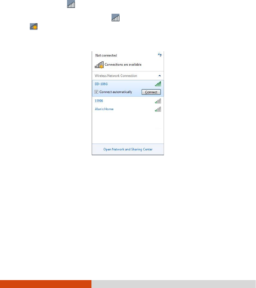
To connect to a wireless network:
1. Make sure that the WLAN function is enabled (as described above). The Wireless
Network icon on the taskbar should appear without a red X.
2. Tap the Wireless Network icon on the taskbar. (An orange light in the icon
indicates connections are available.)
3. In the list of available wireless networks, tap a network, and then tap Connect
ConnectConnect
Connect.
4. Some networks require a network security key or passphrase. To connect to one
of those networks, ask your network administrator or Internet service provider
(ISP) for the security key or passphrase.
For more information on setting a wireless network connection, refer to Windows online
help.
NOTE: You can use Intel® PROSet Wireless to take full advantage of the WiFi
capabilities of your computer. See the Help of the utility for instructions.
Operating Your Computer 2-21
Using the Blue
Using the BlueUsing the Blue
Using the Bluetooth Feature
tooth Featuretooth Feature
tooth Feature
Your computer incorporates the Bluetooth 4.0 capability for short-range (about 50
meters) wireless communications between devices without requiring a cable
connection. With Bluetooth, data can be transmitted through walls, pockets and
briefcases as long as two devices are within range.
Turning Off/On the Bluetooth Radio
Turning Off/On the Bluetooth RadioTurning Off/On the Bluetooth Radio
Turning Off/On the Bluetooth Radio
To turn on or off the wireless radio (including the Bluetooth radio), press the button
located on the front of your computer or spress Fn+F1
Fn+F1Fn+F1
Fn+F1. A small window pops
up on the screen to indicate the status.
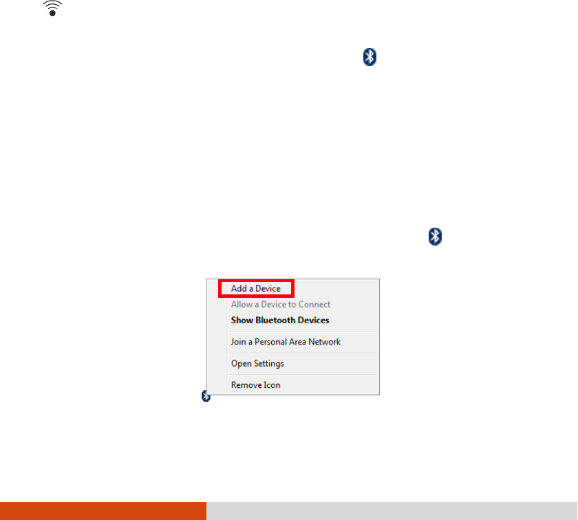
When the Bluetooth radio is on, the Bluetooth icon appears on the Windows
taskbar.
Connecting to another Bluetooth Device
Connecting to another Bluetooth DeviceConnecting to another Bluetooth Device
Connecting to another Bluetooth Device
1. Make sure that the Bluetooth function is enabled (as described above).
2. Make sure that the target Bluetooth device is turned on, discoverable and within
close range. (See the documentation that came with the Bluetooth device.)
3. To search for Bluetooth devices, right click the Bluetooth icon and select Add
a Device.
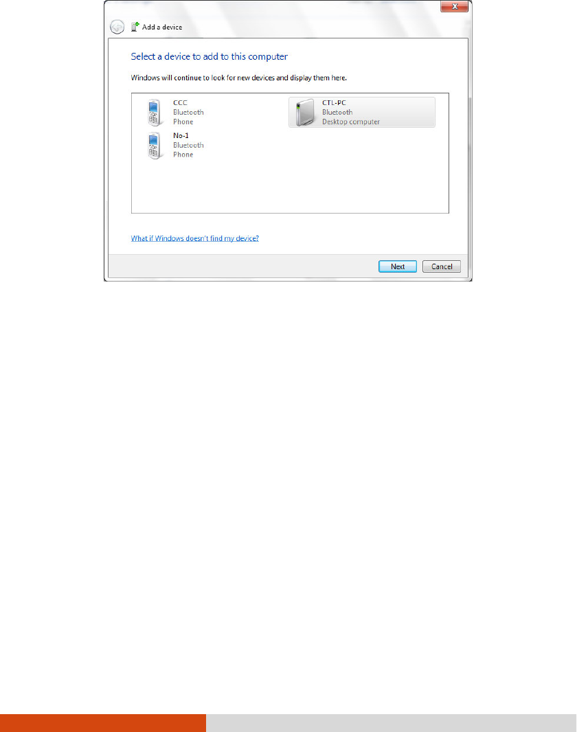
4. Select the device you want to connect from the search results.
2-22 Operating Your Computer
5. Depending on the type of Bluetooth device that you want to connect to, you
will need to enter the pertinent information.
For detailed information on using the Bluetooth feature, see Windows’ online Help.
Operating Your Computer 2-23
Using the WWAN Feature (Option
Using the WWAN Feature (OptionUsing the WWAN Feature (Option
Using the WWAN Feature (Optional)
al)al)
al)
A WWAN (Wireless Wide Area Network) uses mobile telecommunication cellular
network technologies to transfer data. The WWAN module of your computer supports
3G or 4G LTE depending on your model.
NOTE: Your computer only supports data transmission; voice transmission is not
supported.
Installing a SIM Card
Installing a SIM CardInstalling a SIM Card
Installing a SIM Card
To use the WWAN feature to connect to the Internet, you need to subscribe to the
service and acquire a SIM card from a mobile phone network service provider.
To install the SIM card, follow these steps:
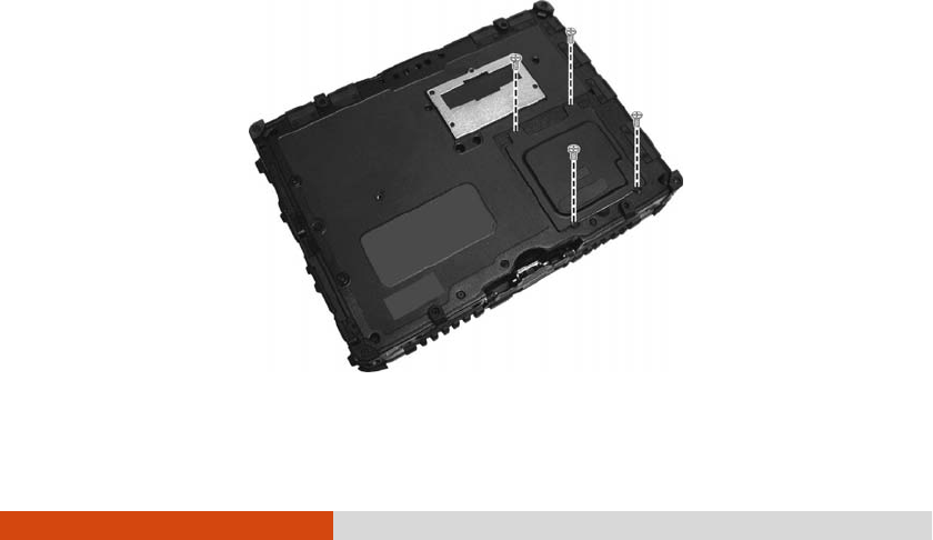
1. Turn off the computer and disconnect the AC adapter.
2. Carefully place the computer upside down.
3. Remove the four screws to open the compartment cover.
2-24 Operating Your Computer
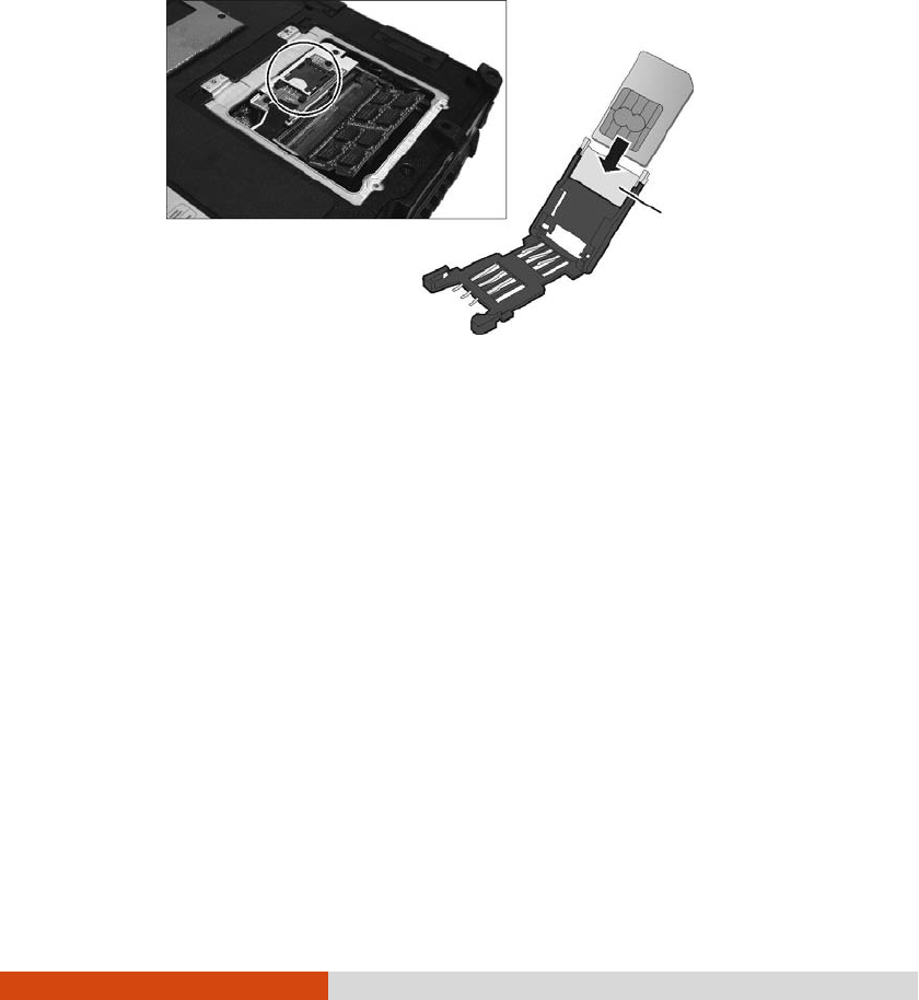
4. Locate the SIM card slot.
Slide the locking tab of the SIM card slot inward to unlock. Lift the slot up
and, noting the orientation, insert the SIM card into the slot. Close the slot and
slide the locking tab outward to secure the card in place.
5. Slide the locking tab outward to secure the SIM card in place.
6. Close the compartment cover and secure with four screws.
Turning Off/On the WWAN Radio
Turning Off/On the WWAN RadioTurning Off/On the WWAN Radio
Turning Off/On the WWAN Radio
CAUTION:
For SAR STATEMENT
FCC RF Radiation Exposure Statement
For body worn operation, this device has been tested and meets FCC RF
exposure guidelines that positions the EUT a minimum of 0 cm from the body SAR
information:
1.WWAN transmitter : 0.142W/kg (1g)
2.WLAN transmitter: 0.376 W/kg (1g)
Locking tab
Operating Your Computer 2-25
To turn on or off the wireless radio (including the WWAN radio), press the button
located on the front of your computer. A small window pops up on the screen
to indicate the status.
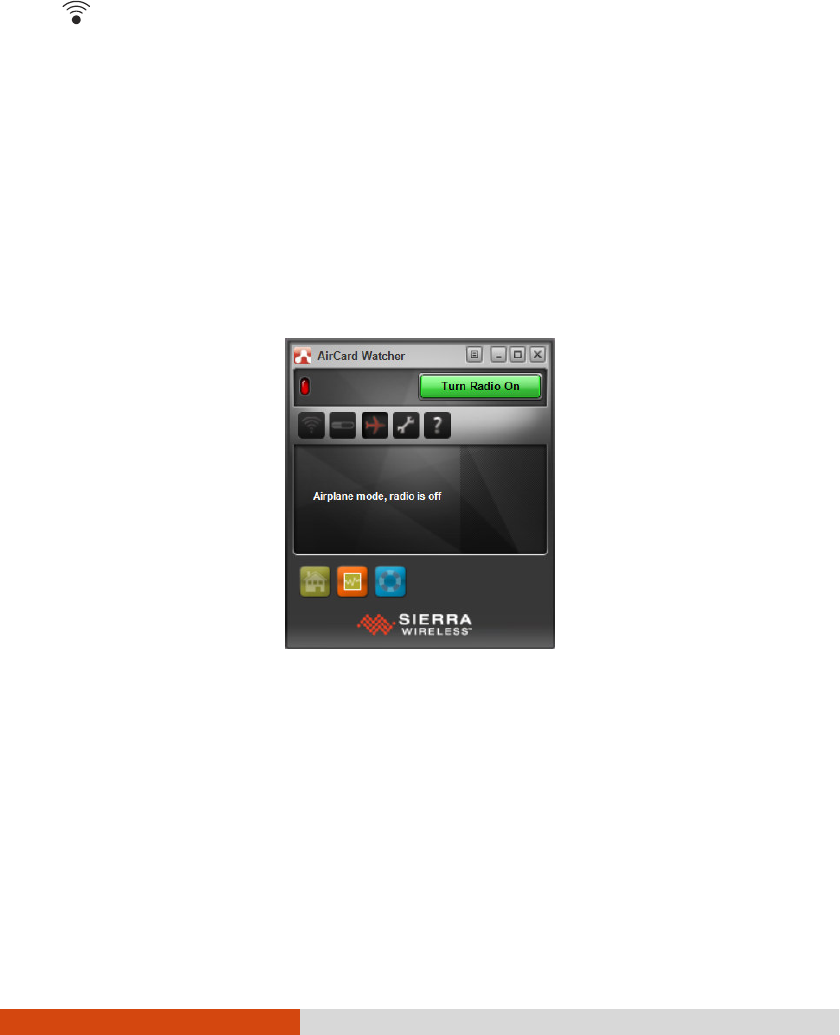
Connecting to WWAN Network
Connecting to WWAN NetworkConnecting to WWAN Network
Connecting to WWAN Network
1. Make sure that the SIM card is inserted and WWAN function is enabled (as
described above).
2. On Windows desktop, double-click the AirCard Watcher
AirCard WatcherAirCard Watcher
AirCard Watcher shortcut. The screen as
below appears.
3. If the radio is currently off, click Turn Radio On
Turn Radio OnTurn Radio On
Turn Radio On to turn on the radio.
4. Use AirCard Watcher to manage your broadband wireless network connections
such as:
Connect to the Internet
Configure user options
Send and receive SMS messages

2-26 Operating Your Computer
Manage profiles
Use GPS to track your position (for models having the GPS module)
NOTE: For detailed information on using AirCard Watcher, see the program’s
online help.

Operating Your Computer 2-27
Using the Fingerpri
Using the FingerpriUsing the Fingerpri
Using the Fingerprint Scanner
nt Scanner nt Scanner
nt Scanner
(Optional)
(Optional)(Optional)
(Optional)
CAUTION:
We shall not be liable for any loss or damage whatsoever resulting from your
use of the fingerprint scanner or neglect of fingerprint scanner use, or any data
loss resulting from such developments as fingerprint authentication
malfunctioning.
It is not recommended that you use the fingerprint scanner in a below-freezing
temperature. The moisture on your finger can freeze to the scanner’s metal
surface when you touch it, resulting in a failed operation.
The fingerprint scanner provides a strong authentication mechanism based on fingerprint
recognition. It features:
Website Log On
Logon to your web accounts like banks, webmail, and more with a simple swipe
of your finger.
Windows Log On
Logon to Microsoft® Windows® with a simple swipe of your finger every time
you turn on your computer or log onto your desktop.
QuickLaunch
Quickly launch all your favorite websites, open files and folders, and log in to
your accounts with a simple swipe of your finger.
KeepSafe
Protect your pictures, personal files, and folders using your fingerprint so only
you can access them.
NOTE: You can register a fingerprint only after creating a password for the
Windows user account.
2-28 Operating Your Computer
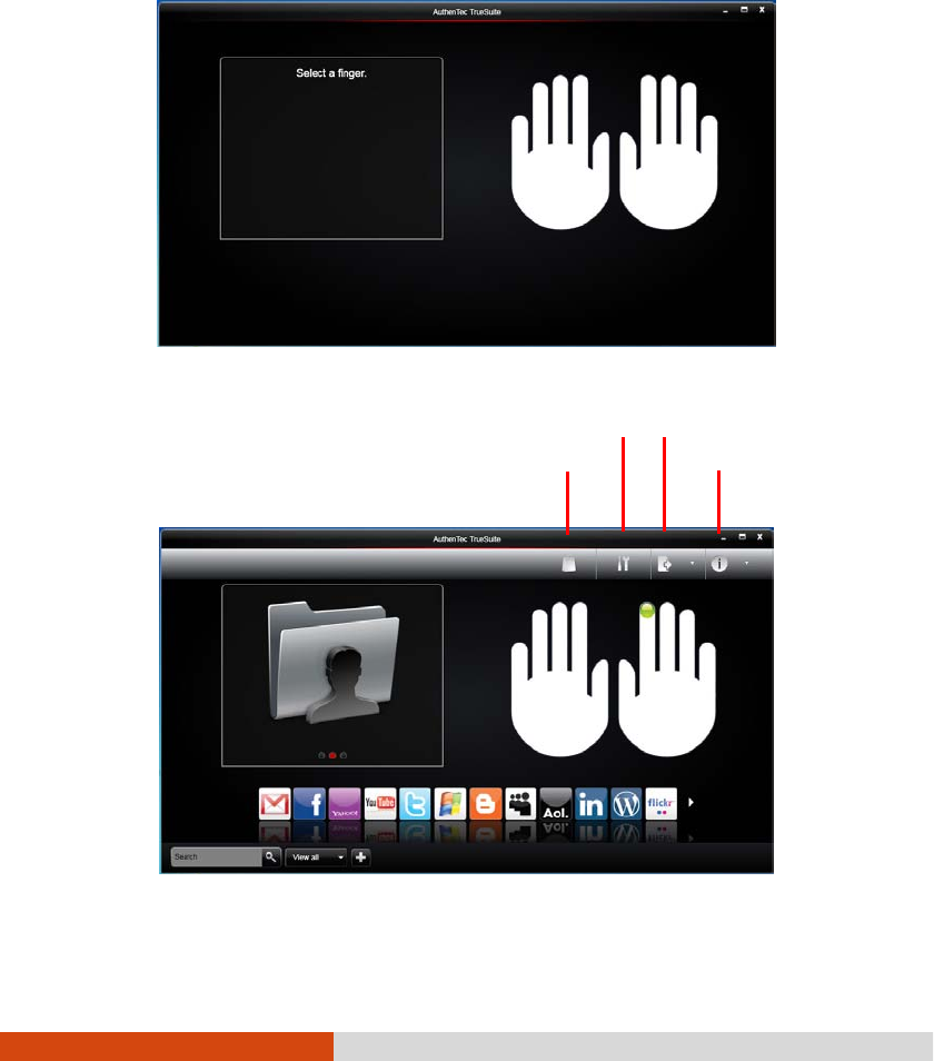
To register your fingerprint, click Start
StartStart
Start All Programs
ProgramsPrograms
Programs AuthenTe
AuthenTeAuthenTe
AuthenTec TrueSuite
c TrueSuitec TrueSuite
c TrueSuite
AuthenTec TrueSuite
AuthenTec TrueSuiteAuthenTec TrueSuite
AuthenTec TrueSuite. Click the finger you want to register and follow the onscreen
instructions to complete.
You can then use the Fingerprint Software to set up how the fingerprint authentication
works.
App Store
Settings
Options
Help

Operating Your Computer 2-29
For detailed information, click
the Help button of the software.

Managing Power 3-1
Chapter 3
Chapter 3Chapter 3
Chapter 3
Managing Power
Managing PowerManaging Power
Managing Power
Your computer operates either on external AC power or on internal battery power.
This chapter tells you how you can effectively manage power. To maintain optimal
battery performance, it is important that you use the battery in the proper way.

3-2 Managing Power
AC Adapter
AC AdapterAC Adapter
AC Adapter
CAUTION:
The AC adapter is designed for use with your computer only. Connecting the
AC adapter to another device can damage the adapter.
The AC power cord supplied with your computer is for use in the country where
you purchased your computer. If you plan to go overseas with the computer,
consult your dealer for the appropriate power cord.
When you disconnect the AC adapter, disconnect from the electrical outlet first
and then from the computer. A reverse procedure may damage the AC
adapter or computer.
When unplugging the connector, always hold the plug head. Never pull on the
cord.
The AC adapter serves as a converter from AC (Alternating Current) to DC (Direct
Current) power because your computer runs on DC power, but an electrical outlet
usually provides AC power. It also charges the battery pack when connected to AC
power.
The adapter operates on any voltage in the range of 100~240 V AC.

Managing Power 3-3
Battery Pack
Battery PackBattery Pack
Battery Pack
The battery pack is the internal power source for the computer. It is rechargeable
using the AC adapter.
The operating time of a fully charged battery pack depends on how you are using
the computer. When your applications often access peripherals, you will experience
a shorter operating time.
NOTE: Care and maintenance information for the battery is provided in the
“Battery Pack” section in Chapter 7.
Charging
ChargingCharging
Charging
the Battery Pack
the Battery Packthe Battery Pack
the Battery Pack
NOTE:
Charging will not start if the battery’s temperature is below 0 °C (32 °F) or
above 40 °C (104 °F); the charging process will stop if the battery’s
temperature gets above 60 °C (140 °F). To avoid damaging the battery under
this situation, disconnect the AC adapter and wait for the battery to return to
room temperature before charging again.
During charging, do not disconnect the AC adapter before the battery has
been fully charged; otherwise you will get a prematurely charged battery.
To charge the battery pack, connect the AC adapter to the computer and an electrical
outlet. The Battery Charge Indicator ( ) on the computer glows yellow to indicate
that charging is in progress. You are advised to keep the computer power off while
the battery is being charged. When the battery is fully charged, the Battery Charge
Indicator lights green.
It takes approximately 3 hours to fully charge the Li-Ion battery pack when the
computer is off, and approximately 6 hours to fully charge the Li-Ion battery pack
when the computer is on.

3-4 Managing Power
CAUTION: After the computer has been fully recharged, do not immediately
disconnect and reconnect the AC adapter to charge it again. Doing so may
damage the battery.
NOTE: The battery level may automatically lessen due to the self-discharge
process (0.21 % per day), even when the battery pack is fully charged (100 %).
This happens no matter if the battery pack is installed in the computer.
Initializing the Battery Pack
Initializing the Battery PackInitializing the Battery Pack
Initializing the Battery Pack
You need to initialize a new battery pack before using it for the first time or when
the actual operating time of a battery pack is much less than expected. Initializing
is the process of fully charging, discharging, and then charging. It can take several
hours.
A tool called “Gauge Reset” is provided for the purpose. See “Gauge Reset” in
Chapter 6 for information on using the tool.
Checking the Battery Level
Checking the Battery Level Checking the Battery Level
Checking the Battery Level
NOTE: Any battery level indication is an estimated result. The actual operating
time can be different from the estimated time, depending on how you are using the
computer.
By Operating System
By Operating SystemBy Operating System
By Operating System
You can check the approximate battery level using the battery meter function of the
operating system. To read the battery level in Windows, click the battery icon on
the taskbar.
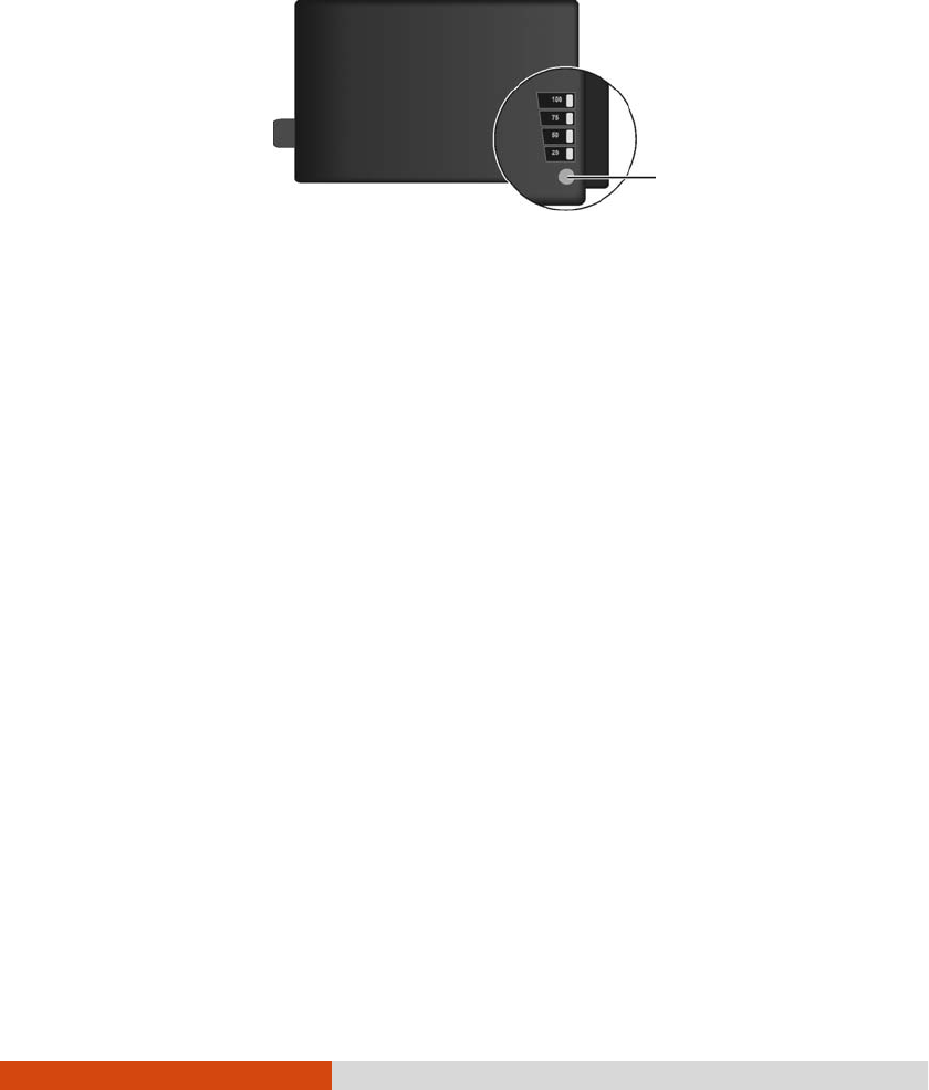
By Gas Gauge
By Gas GaugeBy Gas Gauge
By Gas Gauge
On the exterior side of the battery pack is a gas gauge for displaying the estimated
battery charge. When the battery pack is not installed in the computer and you want
Managing Power 3-5
to know the battery charge, you can press the switch with a pointed device to see
the corresponding value of indicator segment that light green.
The value of the corresponding green segment indicates the relative percentage of
the battery charge. The battery pack is fully discharged when you see no segment
glowing green.
Replacing the Battery Pack
Replacing the Battery PackReplacing the Battery Pack
Replacing the Battery Pack
CAUTION:
There is danger of explosion if the battery is incorrectly replaced. Replace the
battery only with the computer manufacturer’s optional battery packs. Discard
used batteries according to the dealer’s instructions.
Do not attempt to disassemble the battery pack.
If you often rely on battery power for a long period of time while traveling, you
may consider the purchase of an additional battery pack from your dealer and keep
it with you in a fully charged state as a backup.
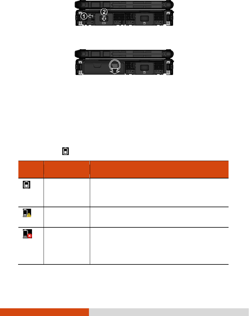
To replace the battery pack, follow these steps:
1. Make sure that the computer is not turned on or connected to AC power.
2. Locate the battery compartment on the right side of the computer.
3. Slide the door lock toward the left to unlock (). Then slide the door latch
downward to open the door ().
Switch
3-6 Managing Power
4. Pull the ribbon strip to remove the battery pack.
5. With the ribbon strip facing outward, slide the new battery pack all the way into
the slot.
6. Close the door. Make sure the door latch clicks into place. Then, slide the door
lock toward the right.
Battery Low
Battery Low Battery Low
Battery Low Signa
SignaSigna
Signals and Action
ls and Actionls and Action
ls and Actions
ss
s
The battery icon changes appearance to display the current state of the battery.
Battery
Battery Battery
Battery
Icon
IconIcon
Icon
Battery Level
Battery LevelBattery Level
Battery Level
Description
DescriptionDescription
Description
Discharging The icon shows the charge remaining in 10-
percent
increments until the charge reaches the low-
battery
level.
Low The battery charge has reached the low-
battery level
(10% by default).
Critically low
The battery charge has reached the critical battery
level (5% by default). By default, Windows will
display a notification and put your computer into
Hibernation.

Managing Power 3-7
When the battery is low, the computer’s Battery Charge Indicator ( ) also
blinks red to alert you to take actions.
Always respond to low-battery by connecting the AC adapter, placing your computer
in Hibernation mode, or turning off the computer.

3-8 Managing Power
Power Management
Power ManagementPower Management
Power Management
Your computer supports ACPI (Advanced Configuration and Power Interface) for
power management. The power management feature allows you to reduce the power
consumption for energy saving.
With an ACPI-compliant operating system such as Windows, power supply to different
computer components is controlled on an as-needed basis. This allows maximum
power conservation and performance at the same time.
In general, Windows’ power management works in this way:
What...
What...What...
What...
When...
When...When...
When...
Power to the hard disk is turned off
When the hard disk has been idle for a set
period.
Power to the display is turned off
When the display has been idle for a set
period.
The computer enters the Sleep
mode.
The hard disk and display are turned
off and the entire system consumes
less power.
When the entire system has been idle for
a set period.
When you manually activate the mode.
The computer enters the Hibernation
mode. (See the next subsection for
more information.)
When the entire system has been idle for
a set period.
When you manually activate the mode.
For detailed information on power management, see Windows’ Help.

Managing Power 3-9
Hibernation
HibernationHibernation
Hibernation
Hibernation is a very useful feature. People frequently open many applications when
they use computers. It takes some time to get all these applications open and running,
and normally they all have to be closed before the computer can be turned off.
When you use the hibernation feature, you do not have to close the applications.
The computer stores the state of your computer to a file on the hard disk and then
shuts down. The next time you turn on your computer, you return to exactly where
you left off.

3-10 Managing Power
Power
PowerPower
Power-
--
-Saving Tips
Saving TipsSaving Tips
Saving Tips
Aside from enabling your computer’s power saving mode (see previous section),
you can do your part to maximize the battery’s operating time by following these
suggestions.
Enter power saving mode when using battery power.
Do not disable automatic power management features.
Decrease the LCD brightness to the lowest comfortable level.
Shorten the length of time before Windows turn off the display.
Many USB devices use power just by being connected. If you use a USB mouse,
you can save power by disconnecting the mouse and using the touchpad. If
you use a USB flash drive, unplug it when you are not using it.
Remove the card (such as PC card, ExpressCard, and Smart Card) if not using
it.
Turn off the wireless radio if you are not using the wireless module (such as
WLAN, Bluetooth, or WWAN).
Turn off the computer when you are not using it.

Expanding Your Computer 4-1
Chapter 4
Chapter 4Chapter 4
Chapter 4
Expanding Your
Expanding Your Expanding Your
Expanding Your
Computer
ComputerComputer
Computer
You can expand the capabilities of your computer by connecting other peripheral
devices.
When using a device, be sure to read the instructions accompanying the device together
with the relevant section in this chapter.
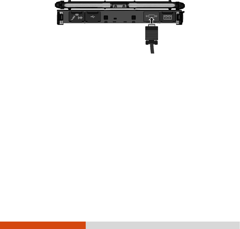
4-2 Expanding Your Computer
Connecting an External Monitor
Connecting an External MonitorConnecting an External Monitor
Connecting an External Monitor
If you want the benefits of a larger display screen with higher resolution, you can
connect an external display monitor to your computer. Follow this procedure to connect
an external monitor:
1. Make sure that the computer is not turned on.
2. Plug the monitor’s D-type signal connector to the computer’s VGA connector.
3. Plug one end of the monitor’s power cord into the power socket on the monitor
and the other end to an electrical outlet.
4. To use the monitor, turn on the monitor before turning on the computer.
5. The monitor should respond by default. If not, you can switch the display to
the monitor or to both (simultaneous display), or to multi-display by pressing
the Fn
FnFn
Fn+F5
F5F5
F5 hot key. In Windows, you can also change the display through the
settings in Display
DisplayDisplay
Display Properties.
6. You can change display settings through your operating system. See your operating
system documentation or online help for specific information.
CAUTION: Do not disconnect the external monitor while the computer is in the
Sleep mode or Hibernation mode. If no external monitor is connected when the
computer resumes, the LCD might not display properly.
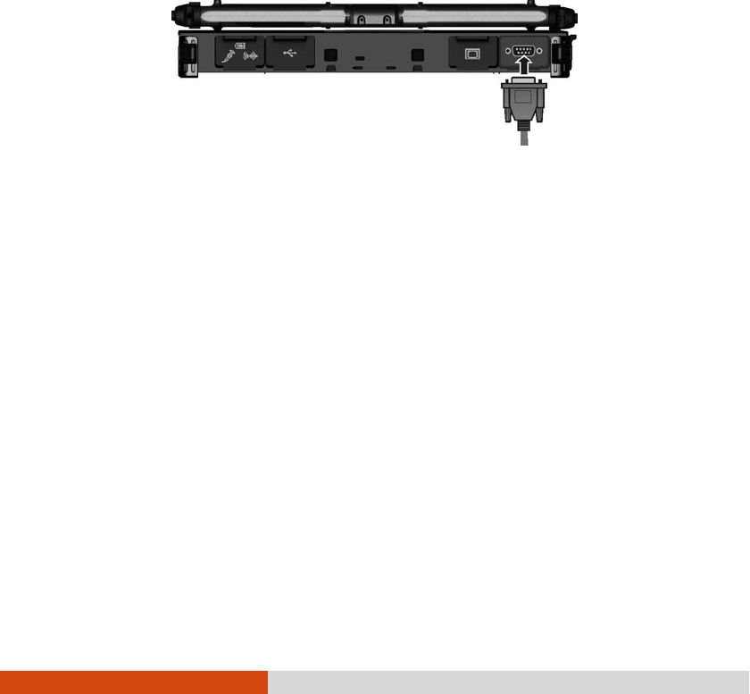
Expanding Your Computer 4-3
Connecting a Serial Device
Connecting a Serial DeviceConnecting a Serial Device
Connecting a Serial Device
Your computer has one or two serial port (depending on model) for connecting
a serial device such as a serial mouse or serial communication device (modem).
Follow this procedure to connect a serial device:
1. Make sure the computer is not turned on
2. Plug the device cable to the serial port on the rear of the computer.
3. Turn on the computer.
NOTE: Portable modems that derive power through the serial port cannot be used
with the computer. Instead, use a modem that is powered by its own internal
battery or external AC power.

4-4 Expanding Your Computer
Connecting a USB Device
Connecting a USB DeviceConnecting a USB Device
Connecting a USB Device
Your computer has three USB ports (two USB 3.0 ports at the left side and one
USB 2.0 port at the back) for connecting USB devices, such as a digital camera,
scanner, printer, modem, and mouse.
USB 3.0 supports a transfer rate up to 5 Gbit/s and USB 2.0 a transfer rate up
to 12 MB/s.
To connect a USB device, plug the device cable to a matching USB port.
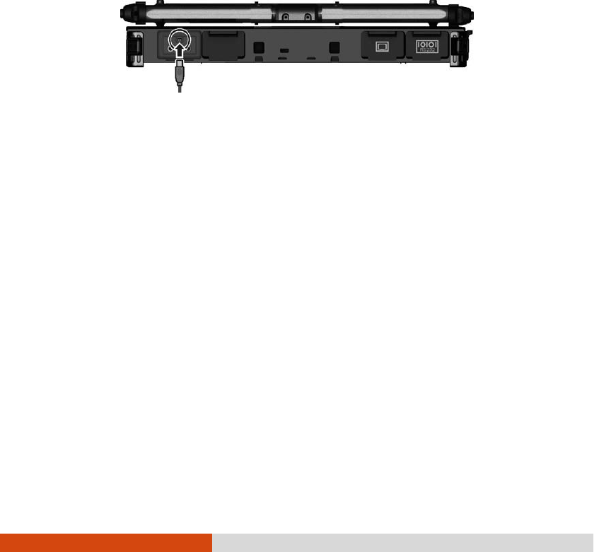
Expanding Your Computer 4-5
Connecting an IEEE 1394 Device
Connecting an IEEE 1394 DeviceConnecting an IEEE 1394 Device
Connecting an IEEE 1394 Device
Your computer has a mini IEEE 1394a port for connecting IEEE 1394 devices that
include not only computer peripheral devices such as scanner, printer and high-quality
CCD, but also consumer electronic equipment such as DVCAM and VCR.
To connect an IEEE 1394 device, prepare an IEEE 1394 cable. Plug the appropriate
end of the cable to the computer’s mini IEEE 1394 connector and the other end
to the device’s corresponding connector.
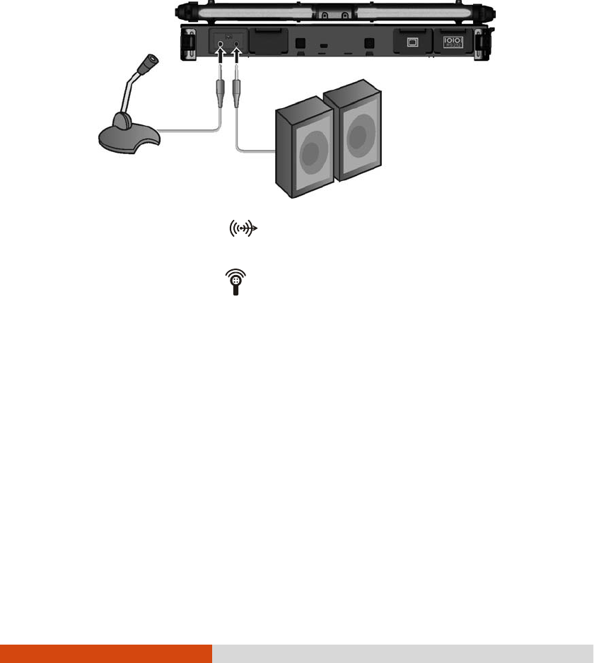
4-6 Expanding Your Computer
Connecting Audio Devices
Connecting Audio DevicesConnecting Audio Devices
Connecting Audio Devices
For higher audio quality, you can send or receive sound through external audio devices.
Audio Output Connector
Audio Output Connector Audio Output Connector
Audio Output Connector ( )
can be connected to speakers, headphones,
or earphone set.
Microphone Connector
Microphone Connector Microphone Connector
Microphone Connector ( )
can be connected to an external microphone
for recording voice or sound.
NOTE:
After connecting an external audio device, make sure that you specify the use
of the correct audio device in Windows.
When using the external speakers/headphones or microphone, you cannot
use the internal one.
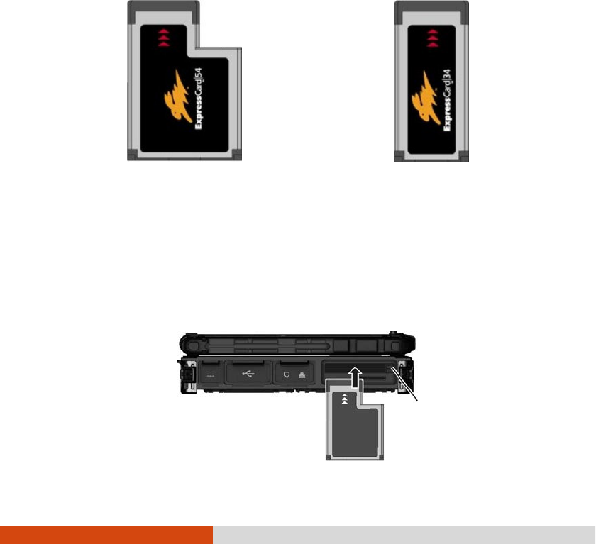
Expanding Your Computer 4-7
Using ExpressCards
Using ExpressCardsUsing ExpressCards
Using ExpressCards
Your computer has an ExpressCard slot.
The ExpressCard slot can accommodate a 54 mm (ExpressCard/54) or 34 mm
(ExpressCard/34) wide ExpressCard. Typical ExpressCards support a very extensive
range of applications including memory, wired and wireless communication cards, and
security devices.
Shown next are the appearances of ExpressCards for your reference.
ExpressCard/54 ExpressCard/34
To insert an ExpressCard:
1. Locate the ExpressCard slot on the left side of the computer. It can be the
upper slot (standard configuration) or lower slot depending on your model.
2. Slide the ExpressCard, with its label facing up, all the way into the slot until
the rear connectors click into place.
Eject button

4-8 Expanding Your Computer
3. When a new card is seated, the computer will detect it and try to install the
appropriate driver. Follow the on-screen instructions to complete the process.
To remove an ExpressCard:
1. Double-click on the Safely Remove Hardware
Safely Remove Hardware Safely Remove Hardware
Safely Remove Hardware icon ( ) found on the
Windows taskbar and the Safely Remove Hardware
Safely Remove HardwareSafely Remove Hardware
Safely Remove Hardware window appears on screen.
2. Select (highlight) the ExpressCard from the list to disable the card.
3. Push the eject button and the card will slide out slightly.
4. Pull the card out of the slot.
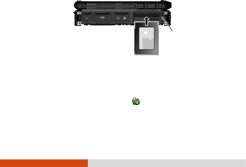
Expanding Your Computer 4-9
Using PC Cards
Using PC CardsUsing PC Cards
Using PC Cards
NOTE:
Some PC cards require additional system resources. Before using such PC
card, you may have to free other system resources for the PC card.
Although some PC cards can be inserted and removed without turning off the
computer, you cannot remove or install PC cards during Sleep mode.
Your computer (standard configuration) has one PC card slot that support CardBus
specifications. The slots can accommodate a type II card. Typical type II cards are
flash memory, SRAM, modem, LAN, and SCSI cards.
To insert a PC card:
1. Locate the PC card slot (the lower slot) on the left side of the computer.
2. Slide the PC card, with its label facing up, into the slot until the eject button
pops out.
3. When a new card is seated, the computer will detect it and try to install the
appropriate driver. Follow the on-screen instructions to complete the process.
To remove a PC card:
1. Double-click the Safely Remove Hardware
Safely Remove Hardware Safely Remove Hardware
Safely Remove Hardware icon found on the Windows taskbar
and the Safely Remove Hardware
Safely Remove HardwareSafely Remove Hardware
Safely Remove Hardware window appears on screen.
2. Select (highlight) the PC card from the list to disable the card.
Eject button

4-10 Expanding Your Computer
3. Push the eject button and the card will slide out slightly.
4. Pull the card out of the slot.
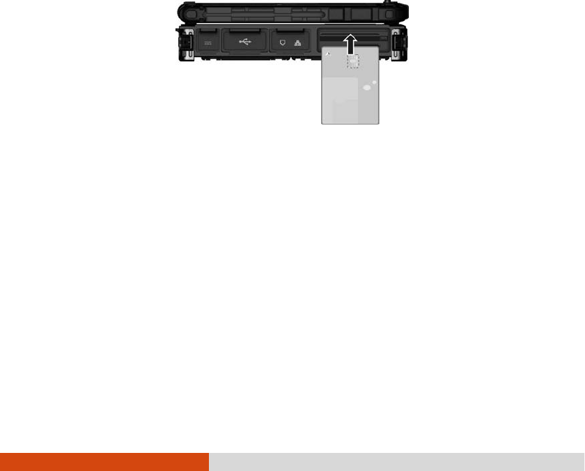
Expanding Your Computer 4-11
Using Smart Cards (Optional)
Using Smart Cards (Optional)Using Smart Cards (Optional)
Using Smart Cards (Optional)
Your computer may have a smart card reader.
With an embedded microcontroller, smart cards have the unique ability to store large
amounts of data, carry out their own on-card functions (e.g., encryption and mutual
authentication), and interact intelligently with a smart card reader.
To insert a smart card:
1. Locate the smart card slot.
2. Slide the smart card, with its label and embedded computer chip facing up into
the slot.
3. When a new card is seated, use the third-party smart card software to allow
your computer to read it.
To remove a smart card:
1. Make sure that the third-party smart card software is not accessing the smart
card.
2. Pull the card out of the slot.
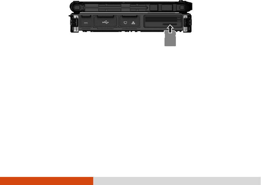
4-12 Expanding Your Computer
Using Storage Cards
Using Storage CardsUsing Storage Cards
Using Storage Cards
NOTE: You can use only storage cards. Your SD card reader does not support
cards with I/O (input/output) functions such as a wireless network card or
Bluetooth card.
Your computer has an SD card reader. The card reader is a small drive for reading
from and writing to removable storage cards (or called memory cards). The card
reader supports SD (Secure Digital), SDHC (Secure Digital High Capacity), and
SDXC (Secure Digital eXtended Capacity) cards.
To insert a storage card:
1. Locate the SD card reader on the left side of the computer.
2. Align the card with its connector pointing to the slot and its label facing up.
Slide the card into the slot until it reaches the end.
3. Windows will detect the card and assign it a drive name.
To remove a storage card:
1. Double-click My Computer
My ComputerMy Computer
My Computer.
2. Right-click the drive with the card and select Eject
EjectEject
Eject.
3. Push the card to release and then pull the card out of the slot.
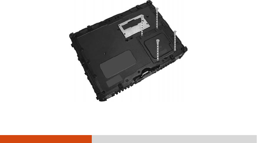
Expanding Your Computer 4-13
System Memory Upgrade
System Memory UpgradeSystem Memory Upgrade
System Memory Upgrade
You can upgrade your computer by expanding system memory.
CAUTION:
It is not recommended that you buy and install RAM modules by yourself. If
you want to expand system memory, please ask Getac service center to install
DRAM modules for you so that full compatibility can be guaranteed.
RAM modules are extremely sensitive to static electricity. There are cases
where static electricity generated by the human body has adversely affected
such modules. When inserting or removing a RAM module, do not touch the
terminals or internal components, insert objects other than the module, or
allow foreign particles to enter. Doing so has been known to cause damage,
fire, or electrical shock.
To install the RAM module:
1. Remove the battery pack (see chapter 3) and make sure that the computer
is not connected to AC power.
2. Carefully place the computer upside down.
3. Remove the four screws to open the compartment cover.
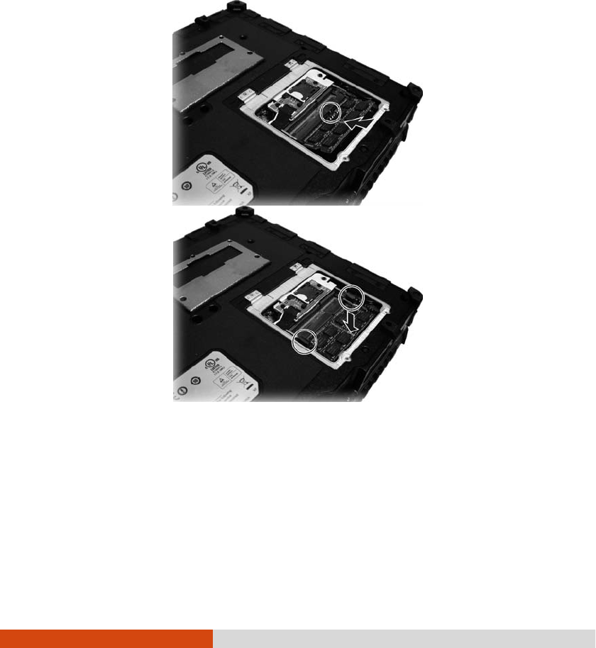
4-14 Expanding Your Computer
4. To install the RAM module, match the module's notched part with the socket's
projected part and firmly insert the module into the socket at a 20-degree angle.
Then push down until the retaining clips lock the module into position.
CAUTION: If the RAM module is difficult to insert or difficult to push down, do not
force it. Check once more to ensure that the module is positioned correctly.
5. Close the compartment cover and secure with four screws.

Using BIOS Setup and System Recovery 5-1
Chapter 5
Chapter 5Chapter 5
Chapter 5
Using BIOS Setup and
Using BIOS Setup and Using BIOS Setup and
Using BIOS Setup and
System Recovery
System RecoverySystem Recovery
System Recovery
BIOS Setup Utility is a program for configuring the BIOS (Basic Input/ Output
System) settings of the computer. BIOS is a layer of software, called firmware, that
translates instructions from other layers of software into instructions that the computer
hardware can understand. The BIOS settings are needed by your computer to identify
the types of installed devices and establish special features.
System Recovery reinstalls Windows to your computer and restores it to the factory
default status.
This chapter tells you how to use the BIOS Setup and System Recovery.

5-2 Using BIOS Setup and System Recovery
BIOS Setup
BIOS SetupBIOS Setup
BIOS Setup
When and How to Us
When and How to UsWhen and How to Us
When and How to Use
ee
e
You need to run BIOS Setup Utility when:
You see an error message on the screen requesting you to run BIOS Setup
Utility.
You want to restore the factory default BIOS settings.
You want to modify some specific settings according to the hardware.
You want to modify some specific settings to optimize the system performance.
To run BIOS Setup Utility, press the F2
F2F2
F2 key when the prompt appears on the screen
during the system startup. The prompt shows up on the screen for only a few seconds.
You must press the F2
F2F2
F2 key quickly. The BIOS Setup Utility main screen appears
as shown next.
Information Main Advanced
Security
Boot Exit
Model NO:
Serial NO:
Asset Tag:
Processor Info:
Installed System Memory:
SATA HDD:
BIOS Revision:
EC Revision:
LAN MAC Address:
IEEE 1394 GUID:
Operating Time:
V200
-G2
RC6XXV0026
Intel(R) Core(TM) i5-3320M CPU @2.60GHz
4096 MB
TOSHIBA MQ01ABD032 – 320.0 GB
R1.50.070520G
R0.50P.070520
00-22-20-0D-98-C0
00-40-D0-01-00-49-00-D6
184 Hours
F1 Help ↑↓
↑↓↑↓
↑↓ Select Item +/- Change Values F9 Setup Defaults
Esc Exit ←→
←→←→
←→ Select Menu Enter Select
Sub-Menu F10 Save and Exit

Using BIOS Setup and System Recovery 5-3
In general, you can use the arrow keys to move around and + / – keys to change
the setup values. Keyboard information can be found at the bottom of the screen.
NOTE:
The BIOS Setup Utility screens shown in this chapter are for your reference
only. The actual items or settings on your computer may differ.
The BIOS Setup Utility program may have been updated after the publication
of this manual.
The settings you select in your operating system might override similar
settings in BIOS Setup Utility.
Information Menu
Information MenuInformation Menu
Information Menu
The Information menu contains the basic configuration information of the system. There
are no user-definable items in this menu.
Information Main Advanced Security Boot Exit
Model NO:
Serial NO:
Asset Tag:
Processor Info:
Installed System Memory:
SATA HDD:
BIOS Revision:
EC Revision:
LAN MAC Address:
IEEE 1394 GUID:
Operating Time:
V100
-G4
RC5XXV0043
Intel(R) Core(TM) i5-3320M CPU @2.60GHz
8192 MB
LITEONIT LAT-128M3S – 128 GB
R1.01.070520U
R0.50M.070520
00-22-20-0D-A8-A7
00-40-D0-01-00-49-00-2D
80 Hours
F1 Help ↑↓
↑↓↑↓
↑↓ Select Item +/- Change Values F9 Setup Defaults
Esc Exit ←→
←→←→
←→ Select Menu Enter Select
Sub-Menu F10 Save and Exit
NOTE: The “Asset Tag” information appears when you have entered the asset
number for this computer using the asset management program. The program is
provided in the Asset tag folder of the Driver disc.
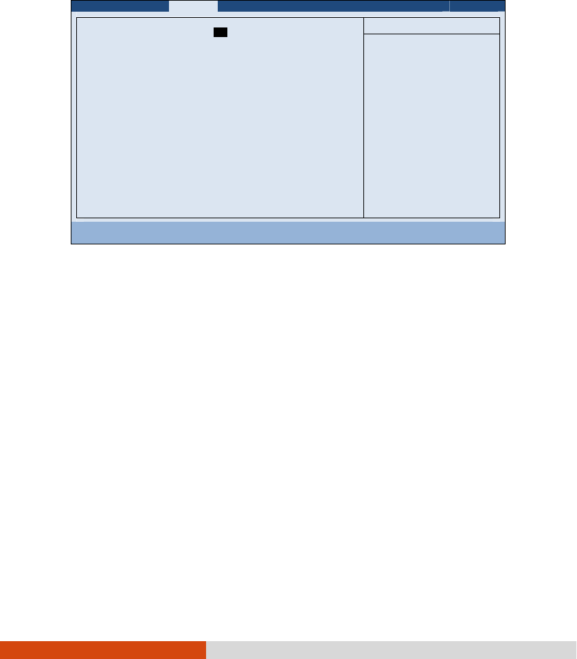
5-4 Using BIOS Setup and System Recovery
Main Menu
Main MenuMain Menu
Main Menu
The Main menu contains various system settings.
Information Main Advanced
Security
Boot Exit
System Date:
System Time:
Legacy USB Support:
[05/28/2012]
[11:33:08]
[Enabled]
Item Specific Help
View or set system
date.
F1 Help ↑↓
↑↓↑↓
↑↓ Select Item +/- Change Values F9 Setup Defaults
Esc Exit ←→
←→←→
←→ Select Menu Enter Select
Sub-Menu F10 Save and Exit
System Time
System TimeSystem Time
System Time sets the system time.
System Date
System DateSystem Date
System Date sets the system date.
Legacy USB Support
Legacy USB SupportLegacy USB Support
Legacy USB Support enables or disables the system’s support for Legacy USB device
in DOS mode.
05
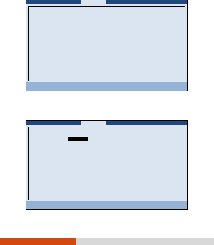
Using BIOS Setup and System Recovery 5-5
Advanced Menu
Advanced MenuAdvanced Menu
Advanced Menu
The Advanced menu contains the advanced settings as shown next.
Information Main Advanced
Security
Boot Exit
Intel (R) Rapid Start Technology
Wake Up Capability
System Policy
AC Initiation:
SATA Mode:
AMT Configuration
Virtualization Technology Setup
Graphic Setup
Device Configuration
Serial COM Port Configuration
[Performance]
[Disabled]
[AHCI]
Item Specific Help
iRST – Intel (R) Rapid
Start Technology
Configuration
F1 Help ↑↓
↑↓↑↓
↑↓ Select Item +/- Change Values F9 Setup Defaults
Esc Exit ←→
←→←→
←→ Select Menu Enter Select
Sub-Menu F10 Save and Exit
Intel (R) Rapid Start Technology
Intel (R) Rapid Start Technology Intel (R) Rapid Start Technology
Intel (R) Rapid Start Technology configures iRST. Press Enter
Enter Enter
Enter to access the submenu
as shown below.
Advanced
Intel (R) Rapid Start Technology Item Specific Help
iRST Support:
[Disabled ]
Enable iRST.
F1 Help ↑↓
↑↓↑↓
↑↓ Select Item +/- Change Values F9 Setup Defaults
Esc Exit ←→
←→←→
←→ Select Menu Enter Select
Sub-Menu F10 Save and Exit
Disabled
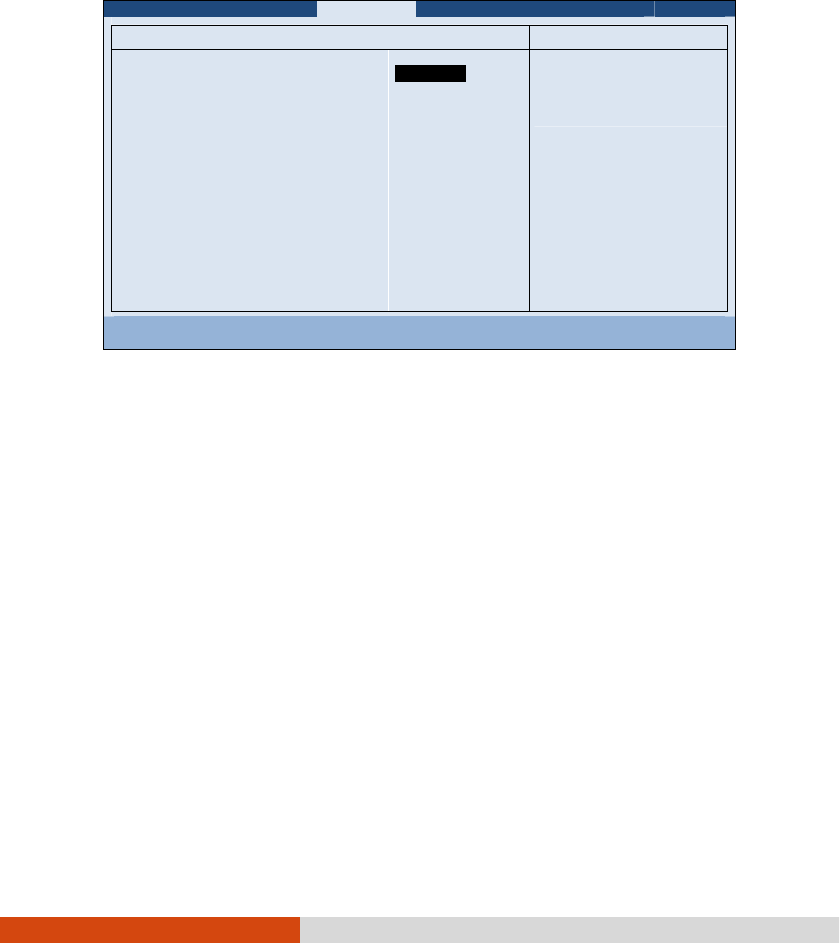
5-6 Using BIOS Setup and System Recovery
iRST Support enables of disables iRST, which gets your system up and running
faster.
Wake Up Capability
Wake Up CapabilityWake Up Capability
Wake Up Capability specifies events for waking up the system. Press Enter
Enter Enter
Enter to access
the submenu as shown below.
Advanced
Wake Up Capability Item Specific Help
Ring Wake Up From S3:
USB Wake Up From S3:
Wake on PCH LAN:
[Disabled]
[Disabled]
[Disabled]
Allow a modem
activity to wake up
the system from
S3(Sleep) state.
F1 Help ↑↓
↑↓↑↓
↑↓ Select Item +/- Change Values F9 Setup Defaults
Esc Exit ←→
←→←→
←→ Select Menu Enter Select
Sub-Menu F10 Save and Exit
Ring Wake Up From S3 allows a modem device activity to wake up the system
from S3 (Sleep) state.
USB Wake Up From S3 allows a USB device activity to wake up the system from
S3 (Sleep) state.
Wake on PCH LAN allows a LAN activity to wake up the system from S3 (Sleep)
state.
System Policy
System Policy System Policy
System Policy sets if the system always runs at full speed (
Performance
) or lowers
down when its temperature is too high (
Balance
).
AC Initiation
AC Initiation AC Initiation
AC Initiation sets if connecting AC power will automatically start or resume your
computer.
SATA Mode
SATA ModeSATA Mode
SATA Mode set to
AHCI
if your hard disk supports AHCI. AHCI allows you to take
advantage of Advanced Host Controller Interface features. The options are
IDE
and
AHCI
.
CAUTION: Incorrect SATA mode settings can result in hard disk drive boot failure.
Disabled
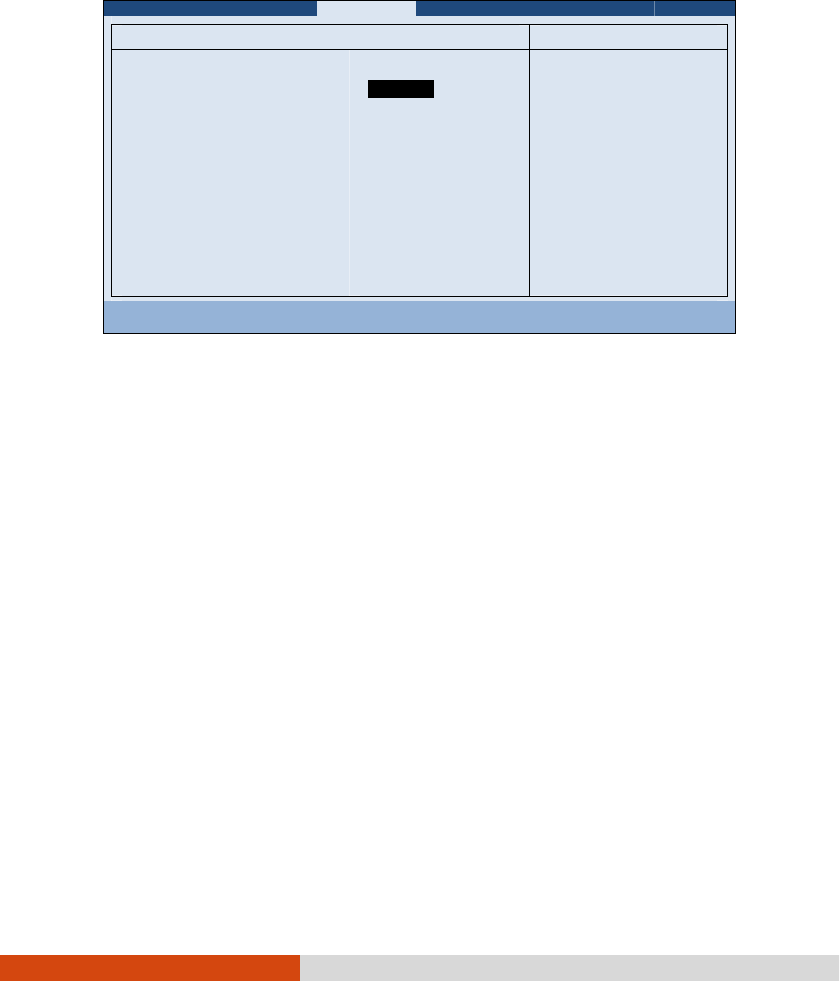
Using BIOS Setup and System Recovery 5-7
AMT Configuration
AMT ConfigurationAMT Configuration
AMT Configuration configures Active Management Technology parameters. Press
Enter
Enter Enter
Enter to access the submenu as shown below.
Advanced
AMT Configuration Item Specific Help
Intel AMT:
Intel AMT Setup Prompt:
[Disable ]
[Disabled]
Enable/Disable
Intel (R) Active
Management Technology
BIOS Extension.
Note: iAMT H/W is
always enabled.
This option just
controls the BIOS
extension execution.
If enabled this
requires additional
firmware in the SPI
device
F1 Help ↑↓
↑↓↑↓
↑↓ Select Item +/- Change Values F9 Setup Defaults
Esc Exit ←→
←→←→
←→ Select Menu Enter Select
Sub-Menu F10 Save and Exit
Intel AMT enables or disables Intel® Active Management Technology BIOS
extension execution. AMT allows the system administrator to access an AMT
featured computer remotely.
Intel AMT Setup Prompt
Intel AMT Setup PromptIntel AMT Setup Prompt
Intel AMT Setup Prompt determines whether the prompt for entering Intel AMT
Setup appears or not during POST. If disabled, users cannot enter Intel AMT
Setup.
Virtualization Technology Setup
Virtualization Technology SetupVirtualization Technology Setup
Virtualization Technology Setup sets Virtualization Technology parameters. Press Enter
Enter Enter
Enter
to access the submenu as shown below.
Enabled
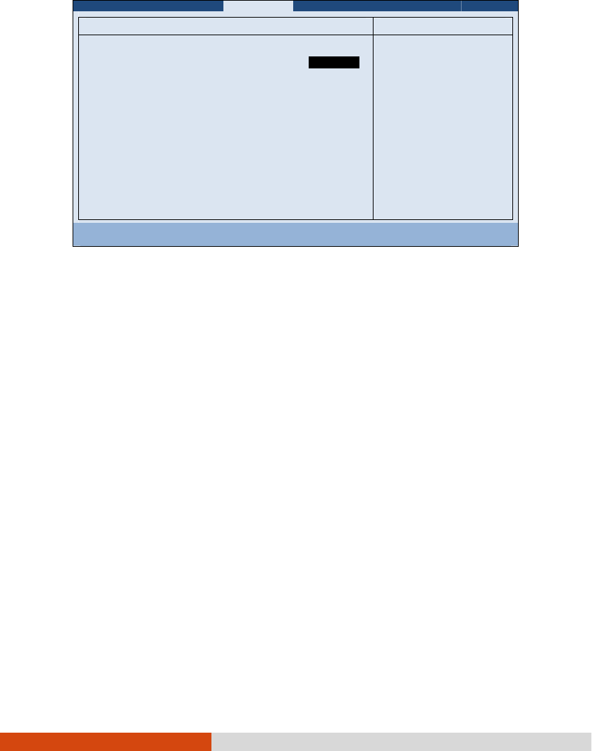
5-8 Using BIOS Setup and System Recovery
Advanced
Virtualization Technology Setup Item Specific Help
Intel(R) Virtualization Technology
Intel(R) VT for Directed I/O (VT-d)
[Disabled]
[Disabled]
When enabled, a VMM
can utilize the
additional hardware
capabilities.
F1 Help ↑↓
↑↓↑↓
↑↓ Select Item +/- Change Values F9 Setup Defaults
Esc Exit ←→
←→←→
←→ Select Menu Enter Select
Sub-Menu F10 Save and Exit
Intel(R) Virtualization Technology
Intel(R) Virtualization TechnologyIntel(R) Virtualization Technology
Intel(R) Virtualization Technology enables or disables Intel® VT (Intel
Virtualization Technology) feature which provides hardware support for processor
virtualization. When enabled, a VMM (Virtual Machine Monitor) can utilize the
additional hardware virtualization capabilities provided by this technology.
Intel(R) VT for Directed I/O (VT
Intel(R) VT for Directed I/O (VTIntel(R) VT for Directed I/O (VT
Intel(R) VT for Directed I/O (VT-
--
-d)
d)d)
d) enables or disables VT-d (Intel® Virtualization
Technology for Directed I/O). When enabled, VT-d helps enhance Intel platforms
for efficient virtualization of I/O devices.
Graphics Setup
Graphics SetupGraphics Setup
Graphics Setup sets graphics related options. Press Enter
Enter Enter
Enter to access the submenu
as shown below.
Disabled
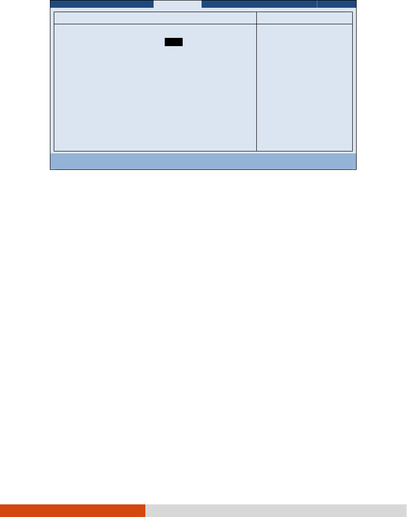
Using BIOS Setup and System Recovery 5-9
Advanced
Graphic Setup Item Specific Help
DVMT Pre-Allocated:
Total Graphics Memory:
[ ]
[256MB]
Select Pre-Allocated
Graphics Memory size
used by the Internal
Graphics Device.
This has no effect if
external graphics are
present.
F1 Help ↑↓
↑↓↑↓
↑↓ Select Item +/- Change Values F9 Setup Defaults
Esc Exit ←→
←→←→
←→ Select Menu Enter Select
Sub-Menu F10 Save and Exit
NOTE: Graphic Setup parameters apply to the internal graphics device only.
DVMT Pre
DVMT PreDVMT Pre
DVMT Pre-
--
-Allocated
Allocated Allocated
Allocated sets the amount of pre-allocated (fixed) graphics memory
for use by the internal graphics device.
Total Graphics Memory
Total Graphics Memory Total Graphics Memory
Total Graphics Memory sets the amount of total graphics memory (pre-allocated
+ fixed + DVMT) for use by the internal graphics device.
64MB
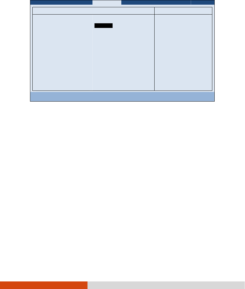
5-10 Using BIOS Setup and System Recovery
Device Configuration enables or disables several hardware components. Press Enter
to access the submenu as shown below.
Advanced
Device Configuration Item Specific Help
Wireless LAN:
WWAN:
Bluetooth:
Media Card Reader:
Smart Card Reader:
HD Audio:
Modem:
Fingerprint Scanner:
1394 Port:
Touch Screen:
GPS:
[ ]
[Enabled]
[Enabled]
[Enabled]
[Enabled]
[Enabled]
[Enabled]
[Enabled]
[Enabled]
[Enabled]
[Enabled]
Set WLAN device to
enable/disable.
F1 Help ↑↓
↑↓↑↓
↑↓ Select Item +/- Change Values F9 Setup Defaults
Esc Exit ←→
←→←→
←→ Select Menu Enter Select
Sub-Menu F10 Save and Exit
You can enable or disable the following items:
Wireless LAN
WWAN
Bluetooth
Media Card Reader (SD)
Smart Card Reader
HD Audio (High Definition Audio)
Modem
Fingerprint Scanner
1394 Port
Touch Screen
GPS
Enabled

Using BIOS Setup and System Recovery 5-11
Serial COM Port Configuration enables or disables the serial port. Press Enter to
access the submenu as shown below.
Advanced
COM PORT Configuration Item Specific Help
Serial COM PORT1
Serial COM PORT2
Serial COM PORT3
[ ]
[Enabled]
[Enabled]
This option controls
the Onboard COM1
Address. When
enabled, COM1 uses
address 0x3F8h and
IRQ4.
F1 Help ↑↓
↑↓↑↓
↑↓ Select Item +/- Change Values F9 Setup Defaults
Esc Exit ←→
←→←→
←→ Select Menu Enter Select
Sub-Menu F10 Save and Exit
Enabled
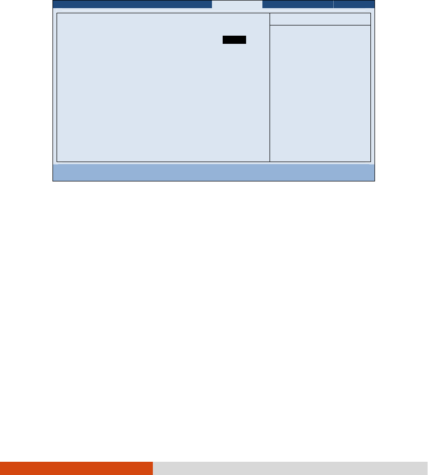
5-12 Using BIOS Setup and System Recovery
Security Menu
Security MenuSecurity Menu
Security Menu
The Security menu contains the security settings, which safeguard your system against
unauthorized use.
Information Main Advanced
Security
Boot Exit
Supervisor Password Is:
User Password Is:
Set Supervisor Password:
Set User Password
Password on Boot:
Set HDD 0 Password:
HDD 0 Password:
TPM Setup Menu
Intel Trusted Execution Technology
Cleared
Cleared
[Enter]
[Enter]
[Disabled]
[Enter]
Cleared
[Disabled]
Item Specific Help
Set or clear the
Supervisor account’s
password.
F1 Help ↑↓
↑↓↑↓
↑↓ Select Item +/- Change Values F9 Setup Defaults
Esc Exit ←→
←→←→
←→ Select Menu Enter Select
Sub-Menu F10 Save and Exit
NOTE:
You can set the user password only when the supervisor password has been
set.
If both the administrator and user passwords are set, you can enter any of
them for starting up the system and/or entering BIOS Setup. However, the
user password only allows you to view/change the settings of certain items.
A password setting is applied right after it is confirmed. To cancel a password,
leave the password empty by pressing the Enter key.
Supervisor/User Password Is
Supervisor/User Password Is Supervisor/User Password Is
Supervisor/User Password Is shows whether you have set the supervisor/user
password or not for the system.
Set Supervisor/User Password
Set Supervisor/User PasswordSet Supervisor/User Password
Set Supervisor/User Password sets the supervisor/user password. When typing the
password, first make sure that Num Lock is off, and then type the password in
the entry fields and press Enter
EnterEnter
Enter. Confirm your password by typing it again and pressing
Enter
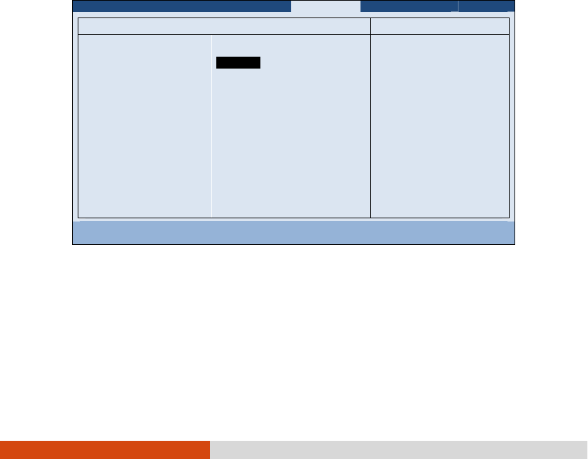
Using BIOS Setup and System Recovery 5-13
Enter
EnterEnter
Enter. You can set the supervisor/user password to be required for starting up the
system and/or entering BIOS Setup.
Password on Boot
Password on BootPassword on Boot
Password on Boot allows you to enable or disable the entering of password for booting
up your system. Once the password is successfully set and this item is enabled,
it is required for booting up the system.
Set HDD
Set HDD Set HDD
Set HDD 0 Password
0 Password0 Password
0 Password sets the password for locking the Primary Master hard disk
drive. After setting a password, the hard disk drive can only be unlocked by the
password no matter where it is installed.
HDD 0 Password Is
HDD 0 Password Is HDD 0 Password Is
HDD 0 Password Is shows whether you have set the hard disk password or not.
TPM Setup Menu
TPM Setup MenuTPM Setup Menu
TPM Setup Menu sets various TPM parameters. Press Enter
Enter Enter
Enter to access the submenu
as shown below.
T
TT
TPM Support
PM Support PM Support
PM Support enables or disables TPM (Trusted Platform Module) support. TPM
(Trusted Platform Module) is a component on your computer’s mainboard that
is specifically designed to enhance platform security by providing a protected space
for key operations and other security critical tasks.
Security
TPM Setup Menu Item Specific Help
TPM Support:
Current TPM State:
Change TPM Status:
[ ]
[Enabled and Activated]
[No Change]
This is used to
decide whether TPM
support should be
enabled or disabled.
F1 Help ↑↓
↑↓↑↓
↑↓ Select Item +/- Change Values F9 Setup Defaults
Esc Exit ←→
←→←→
←→ Select Menu Enter Select
Sub-Menu F10 Save and Exit
Enabled

5-14 Using BIOS Setup and System Recovery
Current TPM State
Current TPM StateCurrent TPM State
Current TPM State shows the current TPM state.
Change TPM State
Change TPM State Change TPM State
Change TPM State allows you to select between
No Change
,
Clear
,
Deactivate
& Disable
, and
Enable & Activate
.
Intel Trusted Execution Technology enables utilization of additional hardware
capabilities provided by Intel® Trusted Execution Technology.
Boot Menu
Boot MenuBoot Menu
Boot Menu
The Boot menu sets the sequence of the devices to be searched for the operating
system.
Information Main Advanced
Security
Boot Exit
Boot priority order:
1. SATA ODD:
2. SATA HDD1: TOSHIBA MQ01ABD032
3. USB HDD:
4. USB FDD:
5. PCI LAN: IBA GE Slot 00C8 v1365
6. USB ODD:
7. Other HDD:
8. ESATA HDD:
Item Specific Help
Keys used to view or
configure devices:
and
arrows Select a
device. ’+’ and ’-’
moves the device up or
down. ’Shift + 1’
enables or disables a
device. ’Del’ deletes
an unprotected device.
F1 Help ↑↓
↑↓↑↓
↑↓ Select Item +/- Change Values F9 Setup Defaults
Esc Exit ←→
←→←→
←→ Select Menu Enter Select
Sub-Menu F10 Save and Exit
The bootable devices will be automatically detected during POST and shown here,
allowing you to set the sequence that the BIOS uses to look for a device from which
to load the OS.
Below is a brief description of keyboard usage:
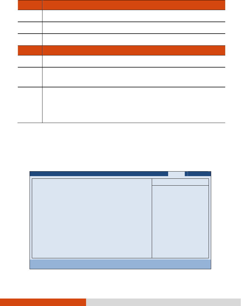
Using BIOS Setup and System Recovery 5-15
Key
KeyKey
Key
Function
FunctionFunction
Function
↑ , ↓ Selects (highlight) a boot device.
+, – Changes the boot sequence.
1
11
1 to 4
44
4 Loads the default boot sequence.
Key
KeyKey
Key
Function
FunctionFunction
Function
f
ff
f or r
rr
r
Specifies if the boot device is fixed (f
ff
f) or removable (r
rr
r).
X
XX
X Moves the
highlighted boot device from the “Boot priority order” list to
the “Excluded from boot order” list, and vice versa.
Shift
ShiftShift
Shift+1
11
1 Deactivates/activates the highlighted boot device on the “Boot priority
order” list. When a device has been deactivated, an “!” (e
xclamation)
symbol appears beside the item and system will bypass it when detecting
boot device during POST.
Exit Menu
Exit MenuExit Menu
Exit Menu
The Exit menu provides ways of exiting BIOS Setup. After finishing with your settings,
you must save and exit so that the changes can take effect.
Information Main Advanced
Security
Boot Exit
Exit Saving Changes
Exit Discarding Changes
Load Setup Defaults
Discard Changes
Save Changes
Item Specific Help
Equal to F10, save
all changes of all
menus, then exit
setup configure
driver. Finally
resets the system
automatically.
F1 Help ↑↓
↑↓↑↓
↑↓ Select Item +/- Change Values F9 Setup Defaults
Esc Exit ←→
←→←→
←→ Select Menu Enter Select
Sub-Menu F10 Save and Exit

5-16 Using BIOS Setup and System Recovery
Exit Saving Changes
Exit Saving Changes Exit Saving Changes
Exit Saving Changes saves the changes you have made and exits BIOS Setup Utility.
Exit Discarding Changes
Exit Discarding Changes Exit Discarding Changes
Exit Discarding Changes exits BIOS Setup Utility without saving the changes you have
made.
Load Setup Defaults
Load Setup DefaultsLoad Setup Defaults
Load Setup Defaults loads the factory default values for all the items.
Discard Changes
Discard Changes Discard Changes
Discard Changes restores the previous values for all the items.
Saves Changes
Saves Changes Saves Changes
Saves Changes saves the changes you have made.

Using BIOS Setup and System Recovery 5-17
System Recovery
System RecoverySystem Recovery
System Recovery
Use System Recovery when:
Your Windows operating system does not start at all.
You want to restore the system to the factory state.
WARNING:
Using this feature will reinstall Windows to your system and configure it to the
system’s factory default settings. All data on the hard disk drive will be lost.
Make sure that power is not interrupted during the recovery process. An
unsuccessful recovery may result in Windows startup problems.
To run System Recovery:
1. Connect the AC adapter.
2. During system startup when the following screen appears, press Ctrl
Ctrl Ctrl
Ctrl + Alt
Alt Alt
Alt + F2
F2F2
F2
keys for four seconds.
3. In the screen that appears, select Recovery
RecoveryRecovery
Recovery to start the recovery process.
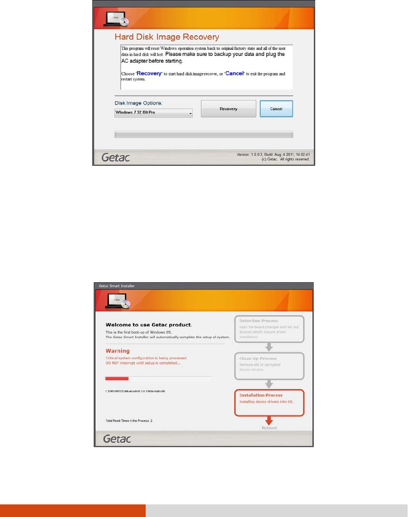
5-18 Using BIOS Setup and System Recovery
4. The progress bar shows the percentage completed. When it reaches 100%, the
system turns off.
5. Turn on the computer. The Windows setup wizard starts. Follow the onscreen
prompts to continue.
6. When the system restarts, the installer screen appears. The installer will perform
system hardware detection and driver installation.

Using BIOS Setup and System Recovery 5-19
7. When completed, the system restarts and displays Windows desktop.

Using Getac Software 6-1
Chapter 6
Chapter 6Chapter 6
Chapter 6
Using Getac Software
Using Getac SoftwareUsing Getac Software
Using Getac Software
Getac software includes application programs for specific computer components and
utility programs for overall management.
This chapter describes how to use the software.
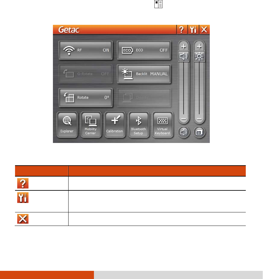
6-2 Using Getac Software
Using the OSD Control Panel
Using the OSD Control PanelUsing the OSD Control Panel
Using the OSD Control Panel
The OSD (On Screen Display) Control Panel provides a user-friendly interface for
you to quickly activate or operate certain functions on your computer with a simple
tap of the screen.
To open the OSD Control Panel, press the button
on the front of your computer.
The following screen appears.
The following table shows the various functions on the OSD Control Panel.
Icon
IconIcon
Icon
Function
FunctionFunction
Function
Opens the Help file explaining the OSD Control Panel.
Opens the Quick Button Setup menu (refer to the next section
for details).
Closes the OSD Control Panel.
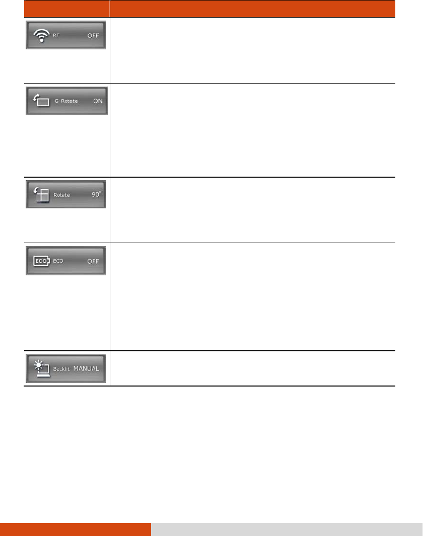
Using Getac Software 6-3
Icon
IconIcon
Icon
Function
FunctionFunction
Function
Serves as the master ON/OFF control of the RF radio. The word
on the button indicates the current status.
The on/off status
will persist through Sleep/Hibernation mode but
it will always be on upon restarting.
Enables or disables the G-
Rotate function. When enabled, the
LCD display will rotate itself to match the direction the computer
is held.
This button is available for u
se only when the computer is in Tablet
mode. The function is automatically enabled whenever you change
the LCD display position to the Tablet style.
Rotates the orientation from default landscape to 90o portrait, 180o
landscape, or 270o portrait.
The st
atus will persist through Sleep/Hibernation mode or system
power off.
Switches the ECO mode to the next choice (MAX, QUICK, WORK
,
or OFF
). The word on the button indicates the current status. (For
information on ECO modes, see “ECO Tab” later in this chapter.)
This button works only when using battery power. The ECO mode
will return to the default OFF setting whenever AC power is
connected, backlight status is changed, the system resumes from
Sleep/Hibernation mode, or the system is restarted.
Switches the LCD backlight to the next choice (MAX
MAXMAX
MAX, AUTO
AUTOAUTO
AUTO, or
MANUAL
MANUALMANUAL
MANUAL.) The word on the button indicates the current status.
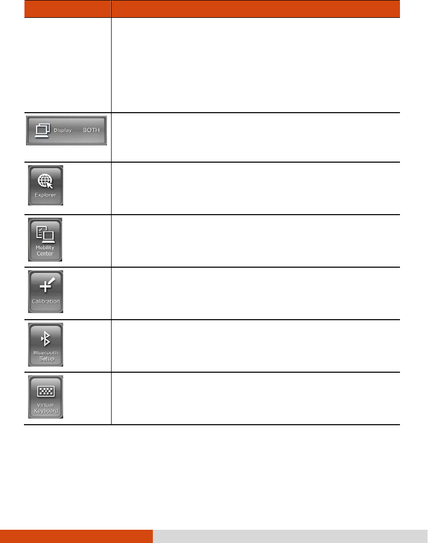
6-4 Using Getac Software
Icon
IconIcon
Icon
Function
FunctionFunction
Function
When set to MAX
MAXMAX
MAX
, the backlight is adjusted to the highest brightness
level. When set to AUTO
AUTOAUTO
AUTO, the brightness will be automatically
adjusted according to the current ambient light.
The backlight will return to the default MANUAL
MANUALMANUAL
MANUAL
setting whenever
the system resumes from Sleep/Hibernation mode or the system
is restarted.
Switches the display output to the next choice: VGA
(external
monitor), BOTH (LCD and external monitor), or LCD.
This button works only when an external display is connected.
Starts Microsoft Internet Explorer by default.
You can assign a different function to
this button (refer to the
next section for details).
Starts Windows Mobility Center by default.
You can assign a different function to this button (refer to the
next section for details).
Starts the touchscreen calibration tool by default.
You can as
sign a different function to this button (refer to the
next section for details).
Starts the Bluetooth Setup utility by default.
You can assign a different function to this button (refer to the
next section for details).
Opens the Input Panel by default.
You can assign a different function to this button (refer to the
next section for details).
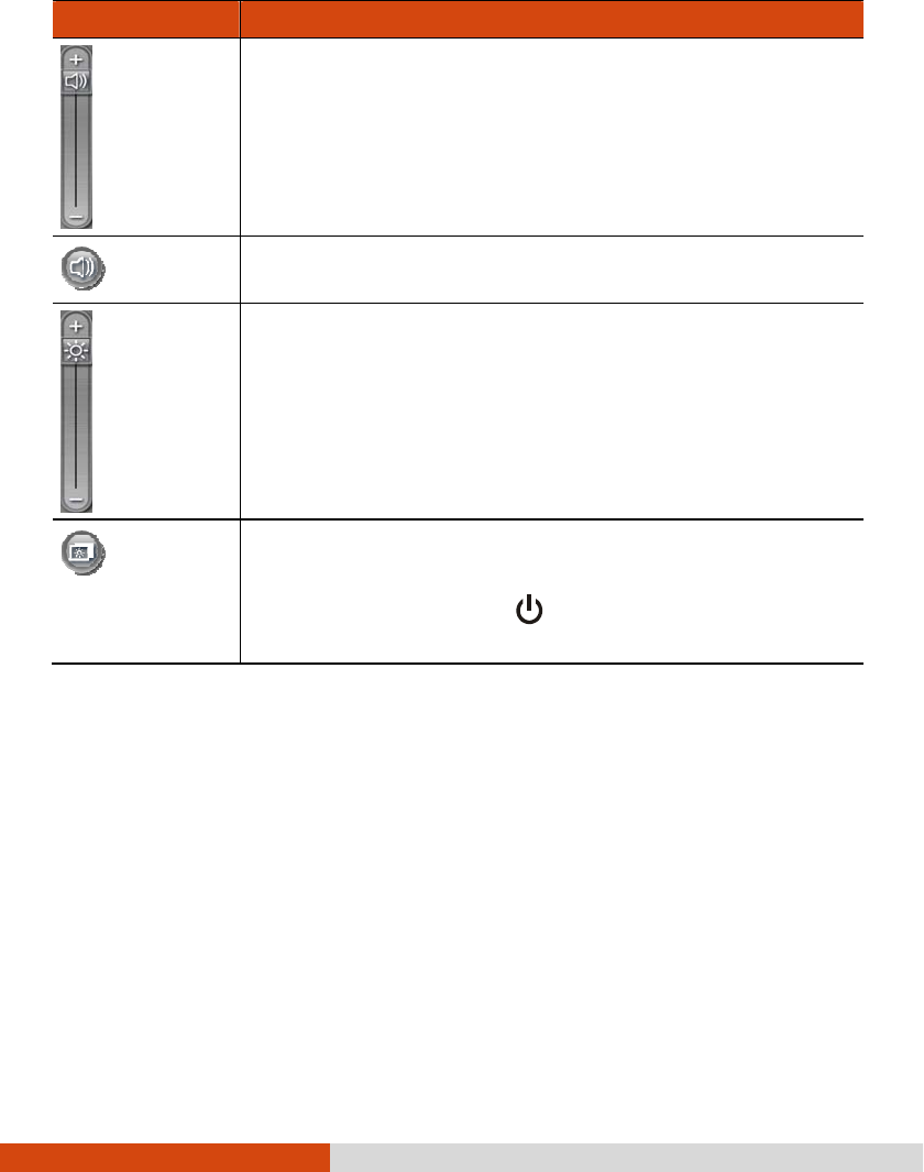
Using Getac Software 6-5
Icon
IconIcon
Icon
Function
FunctionFunction
Function
Allows you to adjust the sound volume by dragging the knob along
the bar.
Switches the system sound output OFF (mute) and ON.
Allows you to adjust the LCD brightness level by dragging the
knob along the bar.
System enters “black-
out” mode by turning off the LCD display,
LED indicators, touchscreen, and sound.
Press the power button (
) to wake up the system from
“black-out” mode.
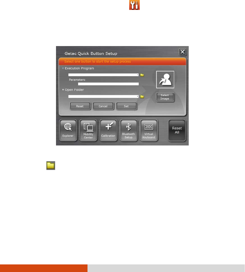
6-6 Using Getac Software
Quick Button Setup
Quick Button SetupQuick Button Setup
Quick Button Setup
By default, the five quick buttons on the OSD Control Panel have pre-assigned
functions. You can re-define the buttons:
1. Click the Quick Button Setup button ( ) on the OSD control panel and
the Quick Button Se
Quick Button SeQuick Button Se
Quick Button Setup
tuptup
tup window appears.
2. At the bottom of the screen are the five quick buttons. Click the button you
want to change.
3. Depending on the type of task to be associated with the button, click the Open
button of the Executed Program or Open Folder type.
4. A dialog box appears. Select the desired program or folder and click Open
OpenOpen
Open or
Select. After your selection, the entry field will display the program or folder
information.
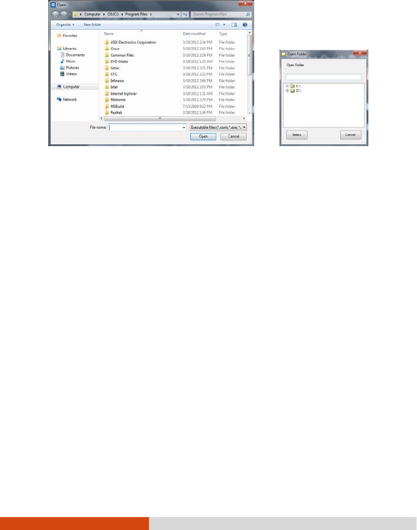
Using Getac Software 6-7
or
5. You can change the image appearing on the button by clicking the Select Image
Select ImageSelect Image
Select Image
button. After selecting the image file, the original image on the button will be
replaced.
6. Click Set
SetSet
Set to complete the changes.
NOTE: You can restore the quick buttons to the default settings by clicking Reset
All.
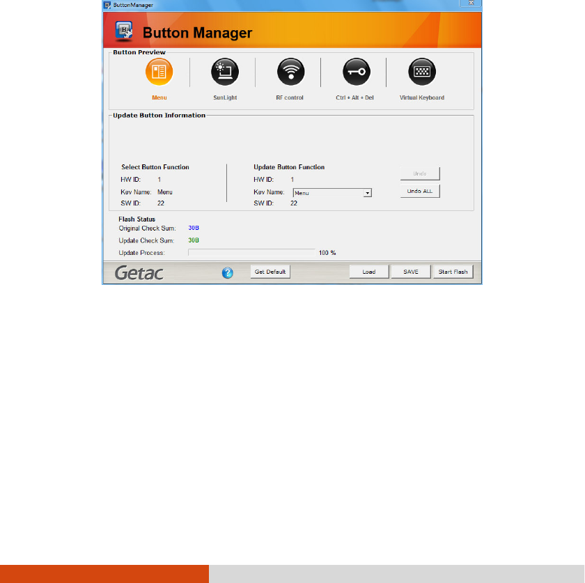
6-8 Using Getac Software
Using Button Manager
Using Button ManagerUsing Button Manager
Using Button Manager
The five quick buttons located on the front of your computer come with predefined
functions. You can use Button Manager to re-define the buttons.
1. Click Start
StartStart
Start Programs
ProgramsPrograms
Programs Button Manager
Button ManagerButton Manager
Button Manager Button Manager
Button ManagerButton Manager
Button Manager. The following
screen appears.
2. Select the button to re-define.
3. Under the Upda
UpdaUpda
Update Button Function
te Button Functionte Button Function
te Button Function click the Key Name
Key NameKey Name
Key Name dropdown list to see the
available options and select the option you want.

Using Getac Software 6-9
The option
User Define Button
(
1
to
5
) means the Quick Button in the OSC
Control Panel.
4. Repeat the steps for the other buttons that you want to re-define.
5. For the changes to take effect immediately, click Start Flash.
6. If you intend to save the configurations for later retrieval, click SAVE. Select a
location, enter a filename, and click Save to save the current configurations as
a .bfh file.
Click Load the next time you use Button Manager to load any previously saved
configurations.
NOTE: You can restore to the default settings by clicking Get Default.

6-10 Using Getac Software
Using G
Using GUsing G
Using G-
--
-Manager
ManagerManager
Manager
G-Manager is a unified user interface utility that allows you to manage and configure
the following:
System
Battery
ECO (economic mode)
Light Sensor
Ignition
Monitoring
GPS Status
Starting G
Starting GStarting G
Starting G-
--
-Manager
ManagerManager
Manager
You can start up G-Manager by any of the following methods:
Click Start All Programs Getac Utility G-Manager, or
Click and hold the icon located on the taskbar until a ring appears. From
the small menu that pops up, click G
GG
G-
--
-Manager
ManagerManager
Manager.
The G-Manager window appears, containing 7 tabs as described later.
NOTE: Depending on your model, the actual items appearing on the screen may
differ from those shown in this manual.
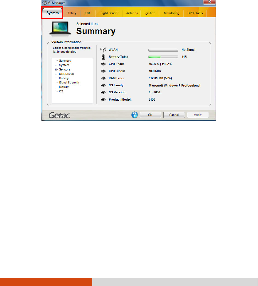
Using Getac Software 6-11
System Tab
System TabSystem Tab
System Tab
The System
SystemSystem
System tab provides system information.
To view specific information, select the component from the list on the left side of
the screen. The information of the selected component will be displayed on the right
side of the screen.
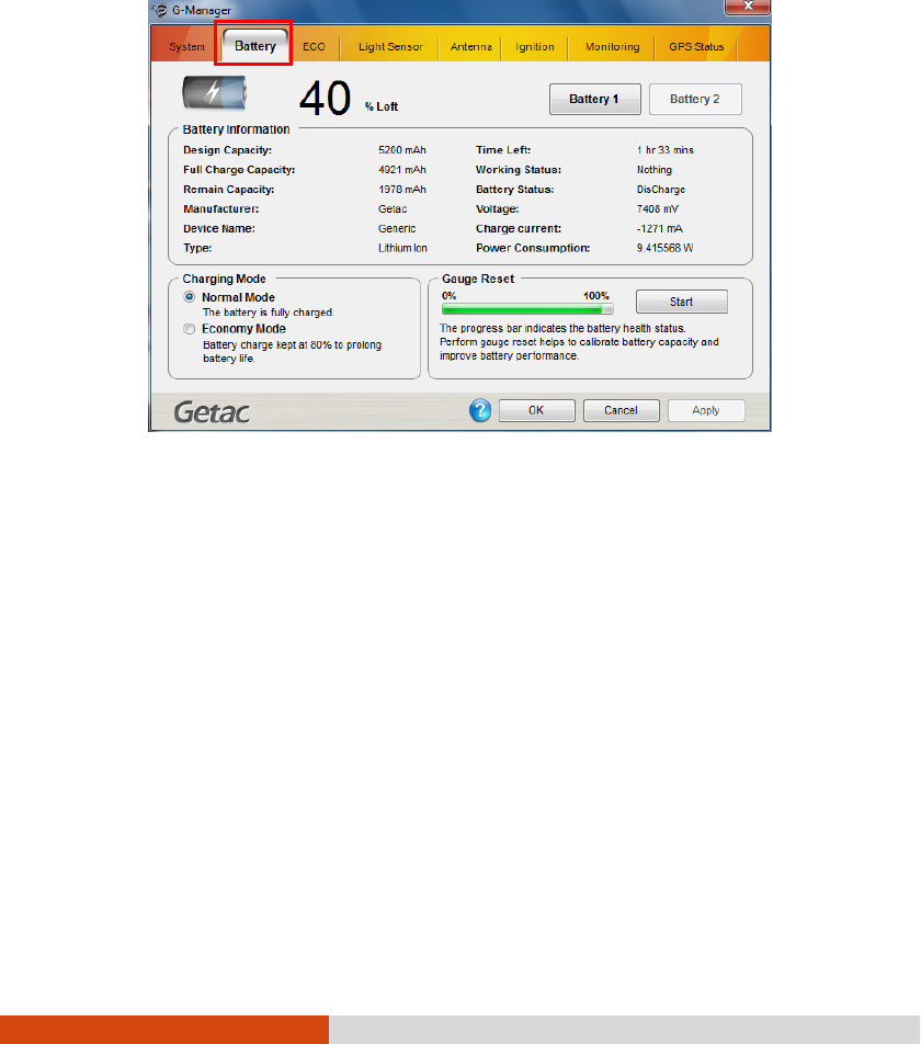
6-12 Using Getac Software
Battery Tab
Battery TabBattery Tab
Battery Tab
The Battery
BatteryBattery
Battery tab allows you to check the battery status and configure the battery.
At most two batteries may be supported. Click Battery 1
Battery 1Battery 1
Battery 1 or Battery 2
Battery 2Battery 2
Battery 2 to view the
information of each battery (if your model has a second battery).
NOTE:
When the percentage % Left
% Left% Left
% Left is less than 10% then the value will be displayed in
red.
When an abnormal battery condition is detected Battery
BatteryBattery
Battery Status
StatusStatus
Status value will be
displayed in red.
Battery Information
Battery InformationBattery Information
Battery Information
The upper portion of the screen displays the current status of the selected battery.

Using Getac Software 6-13
Charging Mode
Charging ModeCharging Mode
Charging Mode
The lower left portion of the screen allows you to select the charging mode.
Normal Mode
Normal ModeNormal Mode
Normal Mode – The battery will be fully charged. When remaining charge reaches
below 95%, then charging will start until it is fully charged.
Economy Mode
Economy ModeEconomy Mode
Economy Mode – This mode helps prolong battery life by charging up to 80%
of its total capacity only. It is highly recommended if you are using AC power
most of the time.
Gauge Reset
Gauge ResetGauge Reset
Gauge Reset
The lower right portion of the screen contains the battery health bar and provides
the battery calibration function.
The health bar shows the batter’s health by percentage. A low percentage indicates
poor health and therefore the need to perform a gauge reset to calibrate the battery’s
capacity and improve the battery’s performance. The gauge reset process includes
discharging and then fully recharging the battery in two cycles. It can take several
hours.
To perform a gauge reset:
1. Connect the AC adapter.
2. Click Start
StartStart
Start, located next to the health bar
3. In the pop-up dialog box, click Yes
YesYes
Yes to start the process. The window as below
appears displaying the progress bar.
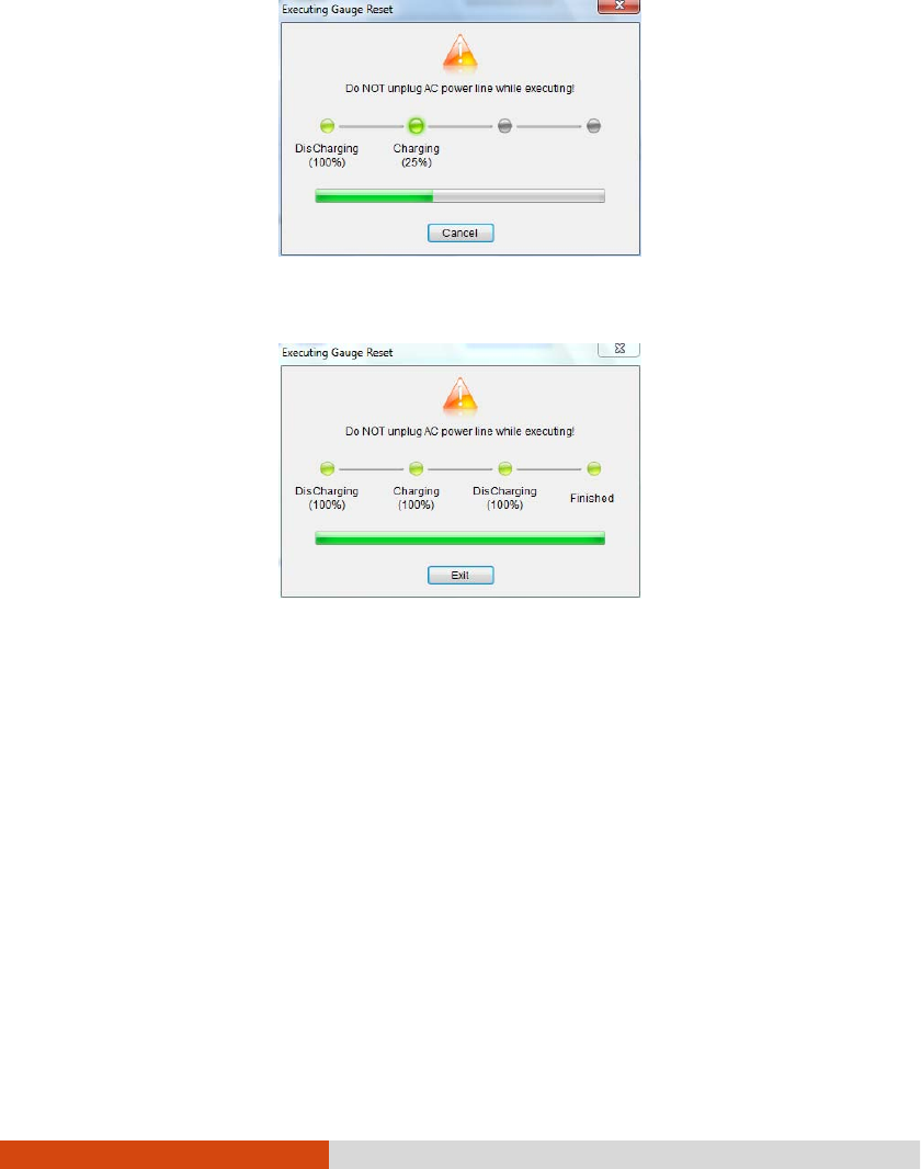
6-14 Using Getac Software
4. Wait till the process is completed. Click Exit
ExitExit
Exit when finished.
ECO Tab
ECO TabECO Tab
ECO Tab
The ECO
ECOECO
ECO tab allows you to configure ECO modes (or called power profiles).
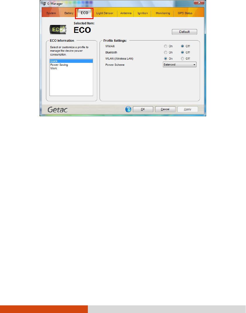
Using Getac Software 6-15
To put the system into an ECO mode, use the ECO button (one of the buttons
in the OSD Control Panel). (See “Using the OSD Control Panel” earlier in this
chapter for information.)
ECO Information
ECO InformationECO Information
ECO Information
The left portion of the screen lists the available power profiles (Quick, Power Saving,
and Work). Each profile is a combination of power settings that results in different
power consumptions. To change the settings of a profile, select (highlight) the profile
name in the list.
Profile Settings
Profile SettingsProfile Settings
Profile Settings
The right portion of the screen displays the settings of the current selected profile.
You can set up the following items:
WWAN, Bluetooth, Touchscreen, and WLAN – can be on or off.

6-16 Using Getac Software
Power Scheme – can be Balanced, High Performance or Power Saver. The settings
here correspond to the settings in Windows. (See Windows Help for the
description to each of the power scheme.)
After changing the settings, click Apply or OK to save the changes. To restore the
settings to the default values, click Default.
Light Sensor Tab
Light Sensor TabLight Sensor Tab
Light Sensor Tab
The Light Sensor
Light SensorLight Sensor
Light Sensor tab allows you configure how the light sensor works.
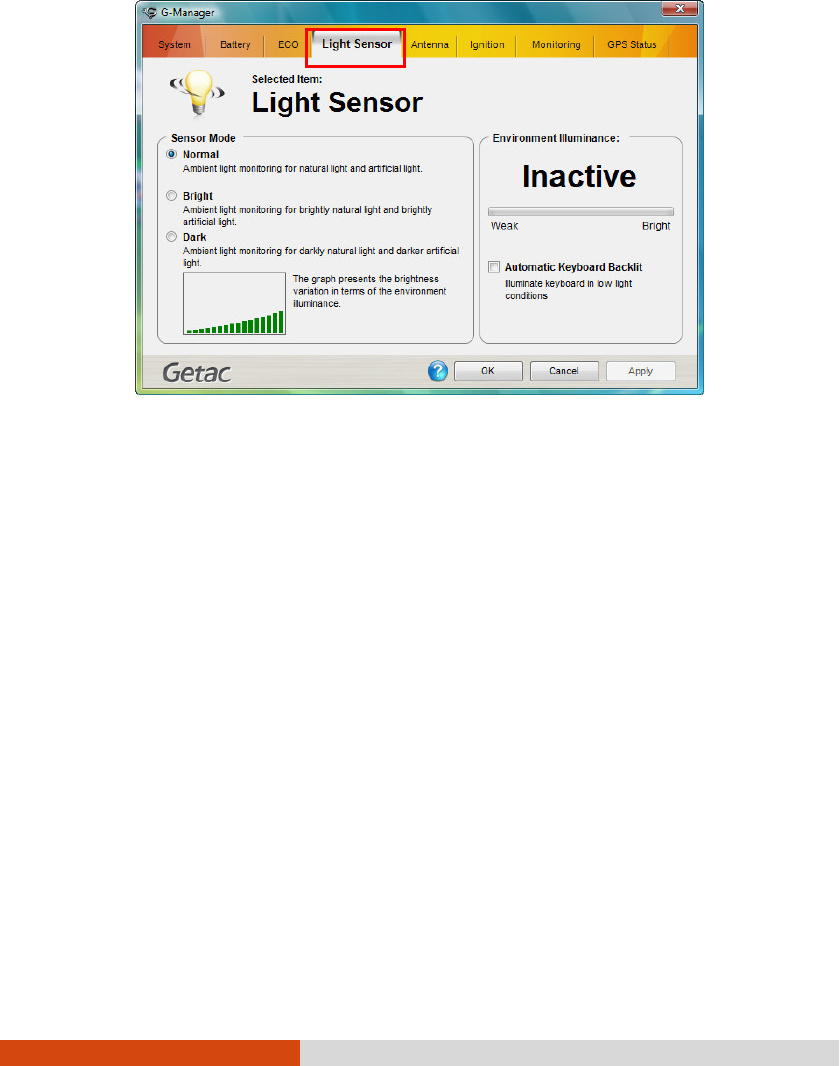
Using Getac Software 6-17
Sensor Mode
Sensor ModeSensor Mode
Sensor Mode
The left portion of the screen lists the sensor modes:
Normal
NormalNormal
Normal – Light sensor sensitivity is set at normal environment lighting condition.
Bright
BrightBright
Bright – Light sensor sensitivity is set at bright environment lighting condition
(e.g. outdoors).
Dark
DarkDark
Dark – Light sensor sensitivity is set at dark environment lighting condition (e.g.
indoors, storage warehouse, etc.).
Click to select a mode. Click Apply
ApplyApply
Apply or OK
OKOK
OK to save the changes.
Environment Illuminance
Environment IlluminanceEnvironment Illuminance
Environment Illuminance
To have the keypad backlight automatically turn on in poor lighting environment, click
the checkbox Automatic Keyboard Backlit
Automatic Keyboard BacklitAutomatic Keyboard Backlit
Automatic Keyboard Backlit. Click
Apply
ApplyApply
Apply or OK
OKOK
OK to save the changes.
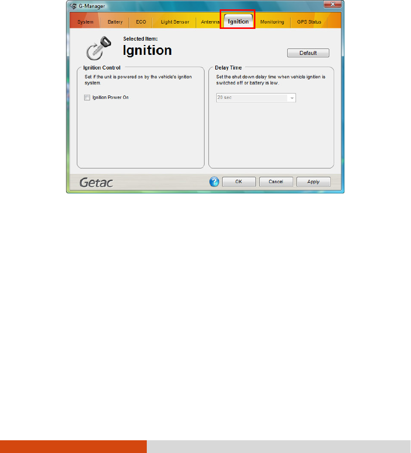
6-18 Using Getac Software
Ignition Tab
Ignition TabIgnition Tab
Ignition Tab
The Ignition
IgnitionIgnition
Ignition tab allows you to configure how your system works with the vehicle
ignition.
Ignition Control
Ignition ControlIgnition Control
Ignition Control
When your system is connected to the Vehicle Dock (available as an option), you
can have your system derive power from the vehicle and have the on/off of the
vehicle ignition turn on/off your system. To enable the feature, select the checkbox
Ignition Power On
Ignition Power OnIgnition Power On
Ignition Power On. Click
Apply
ApplyApply
Apply or OK
OKOK
OK to save the changes.
Delay Time
Delay TimeDelay Time
Delay Time
When the Ignition Power On
Ignition Power On Ignition Power On
Ignition Power On feature is enabled, the system will automatically shut down
after the vehicle ignition is turned off or the battery is low. You can set the amount
of time (20 seconds, 30 seconds, 45 seconds, 1 minute, or 2 minute) the system
waits before shutting down. Click Apply
ApplyApply
Apply or OK
OKOK
OK to save the changes.
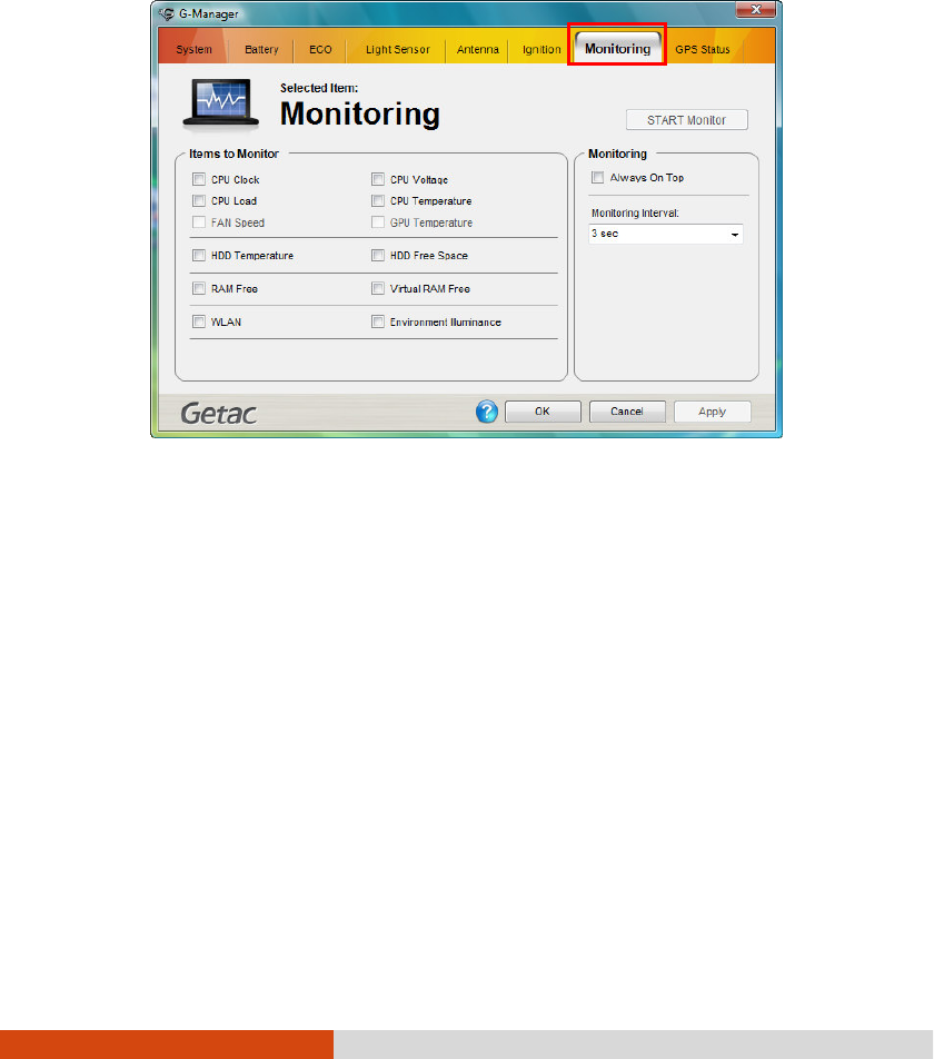
Using Getac Software 6-19
Monitoring Tab
Monitoring TabMonitoring Tab
Monitoring Tab
The Monitoring
MonitoringMonitoring
Monitoring tab allows you to configure the monitoring function of G-Manager.
Items to Monitor
Items to MonitorItems to Monitor
Items to Monitor
The left portion of the screen lists the items. Click the checkbox before an item
to include it as a monitored component. Click Apply
ApplyApply
Apply or OK
OKOK
OK to save the changes.
NOTE: Different models have different supported monitoring items;
non-supported items cannot be selected (grayed out items).
Monitoring Options
Monitoring OptionsMonitoring Options
Monitoring Options
The right portion of the screen allows you to set how the monitored items are displayed
and how often the monitoring is updated.
Always On Top – allows the monitoring window to remain on top of your display.
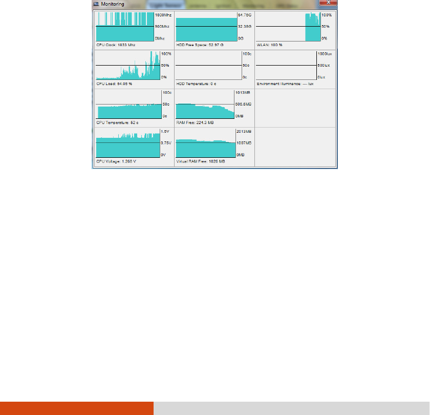
6-20 Using Getac Software
Monitoring Interval – sets the frequency of updates on the monitoring window
(1/3/5/10/30 seconds or 1/5/30 minutes).
Click Apply
ApplyApply
Apply or OK
OKOK
OK to save the changes.
Starting and Stopping the
Starting and Stopping theStarting and Stopping the
Starting and Stopping the
Monitoring
MonitoringMonitoring
Monitoring
To start monitoring, click START Monitor
START MonitorSTART Monitor
START Monitor. The monitoring window similar to the one
below appears displaying requested information at specified intervals.
To stop monitoring, click the Close button at the upper right corner of the monitoring
window or click Stop Monitor
Stop MonitorStop Monitor
Stop Monitor on the Monitoring
Monitoring Monitoring
Monitoring tab page of G-Manager.
GPS Status Tab
GPS Status TabGPS Status Tab
GPS Status Tab
The GPS Status
GPS StatusGPS Status
GPS Status tab shows the GPS status for models having the GPS module.
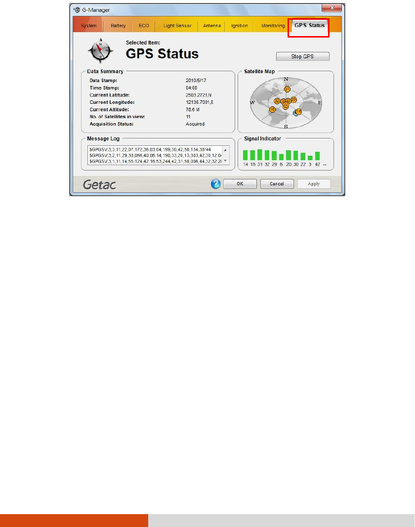
Using Getac Software 6-21
To start GPS positioning, click Start GPS
Start GPSStart GPS
Start GPS. The screen displays:
Ongoing raw data strings in the Message Log
Message LogMessage Log
Message Log section
Overhead satellite positions in the Satellite Map
Satellite MapSatellite Map
Satellite Map section
Signal strength of the satellites in the Signal Indicator
Signal IndicatorSignal Indicator
Signal Indicator section
When GPS positioning is completed, the D
DD
Data Summary
ata Summary ata Summary
ata Summary section shows the GPS
information of the current location.
To stop GPS positioning, click Stop GPS
Stop GPSStop GPS
Stop GPS.
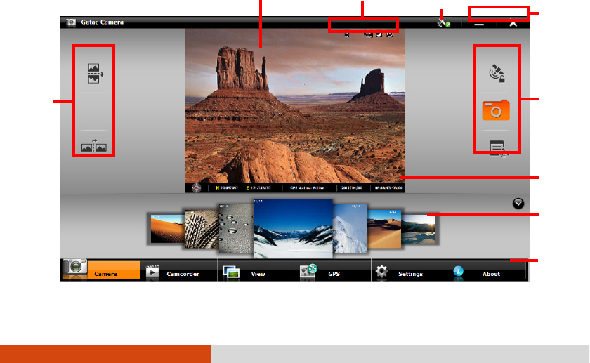
6-22 Using Getac Software
Using Getac Camera
Using Getac CameraUsing Getac Camera
Using Getac Camera
Getac Camera is a geo-tagging camera program, which allows you to stamp
geographical information on photos as watermarks and embed such information into
JPEG files as EXIF 2.2 metadata.
NOTE:
Getac Camera works with Virtual-GPS (a separate application program).
Make sure that Virtual-GPS is installed in your computer.
Before starting Getac Camera, close any other program that uses the
camera; otherwise, Getac Camera can only provide limited functions.
The instructions in this document are based on touchscreen operations
though there are equivalent touchpad and mouse operations.
To start the program, tap the Getac Camera program icon on Windows desktop.
The Getac Camera window appears as shown below.
The GPS positioning will be automatically activated. When the GPS positioning is
completed, you will see the geographical information in the watermark area on the
image.
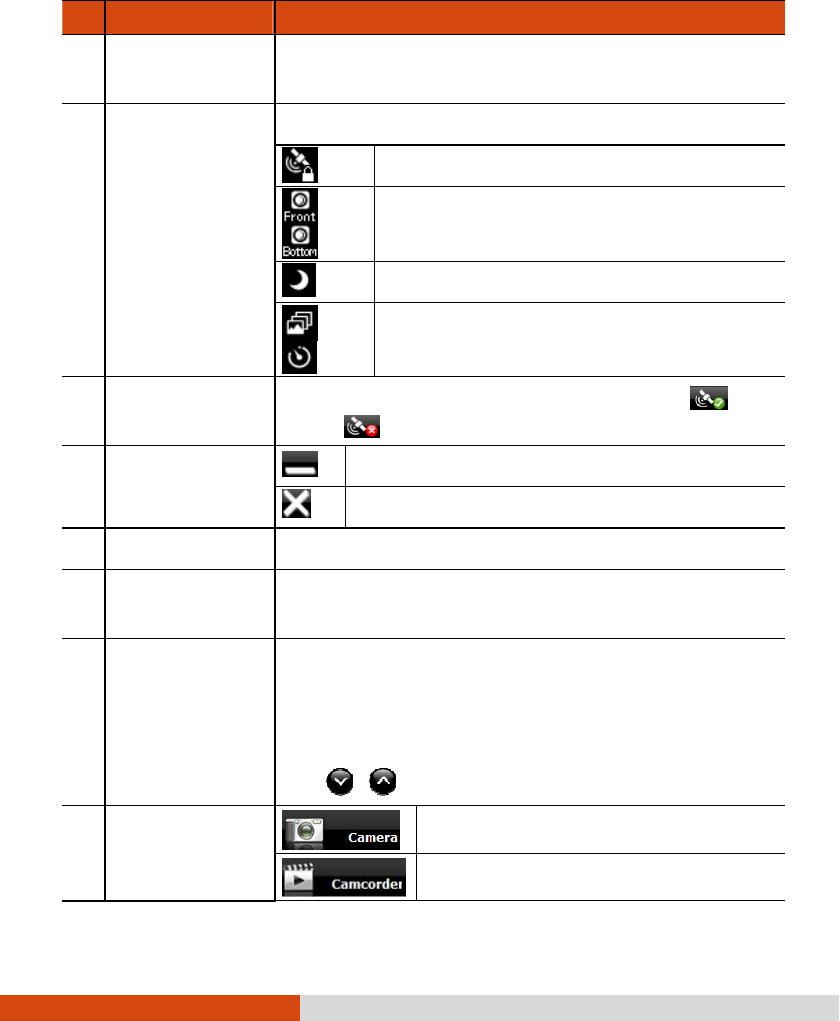
Using Getac Software 6-23
No.
No.No.
No.
Screen Elements
Screen ElementsScreen Elements
Screen Elements
Descriptions
DescriptionsDescriptions
Descriptions
Preview/Display
Window
Displays the live image in Camera mode and the selected
image in View mode.
Status Display Indicates the use of a feature.
GPS Lock in use
/
Front/Bottom camera in use (depending on
your model)
Night mode in use
/
Continuous/Timer mode in use
GPS Status Indicates if the GPS positioning is completed (
) or
not ( ).
Window Control
Buttons
Minimizes the program window.
Closes the program.
Control Buttons Perform immediate tasks on the current image.
Watermark Displays the GPS information such as direction, longi
tude,
latitude, GPS status, date, and time.
Thumbnail Tray
Displays up to 7 pictures in a thumbnail view. The middle
is the picture last taken or selected.
You can drag toward the right or left to scroll through the
thumbnail view.
The / button hides/shows the Thumbnail Tray.
Command Buttons
Switches to Camera Mode.
Switches to Camcorder mode.
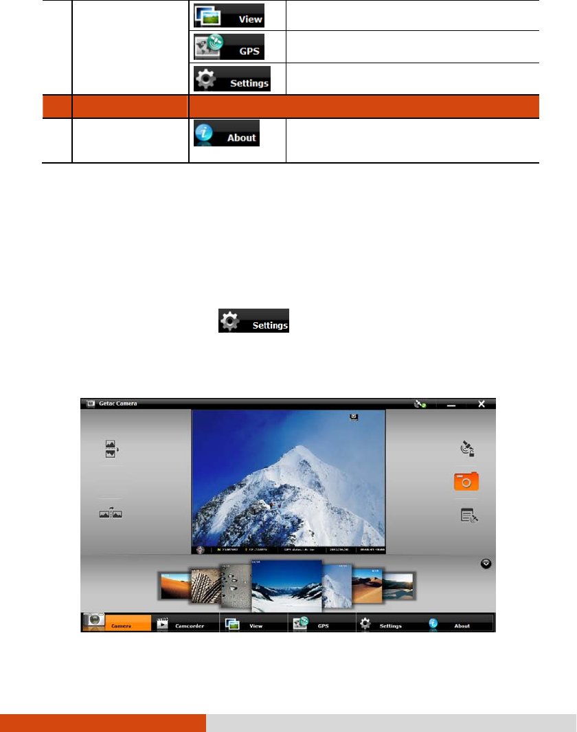
6-24 Using Getac Software
Switches to View Mode.
Switches to GPS view.
Switches to the Settings screen.
No.
No.No.
No.
Screen Elements
Screen ElementsScreen Elements
Screen Elements
Descriptions
DescriptionsDescriptions
Descriptions
Provides copyright, licensing, and help
information.
Taking Pictures
Taking PicturesTaking Pictures
Taking Pictures
1. Start the Getac Camera program. You will be in Camera Mode.
2. You can use the buttons on the right and left side of the preview window for
immediate controls. (See “Camera Controls Buttons” for detailed information.)
For overall settings, tap . (See “Camera Settings” for detailed
information.)
3. Aim the camera lens at your subject.
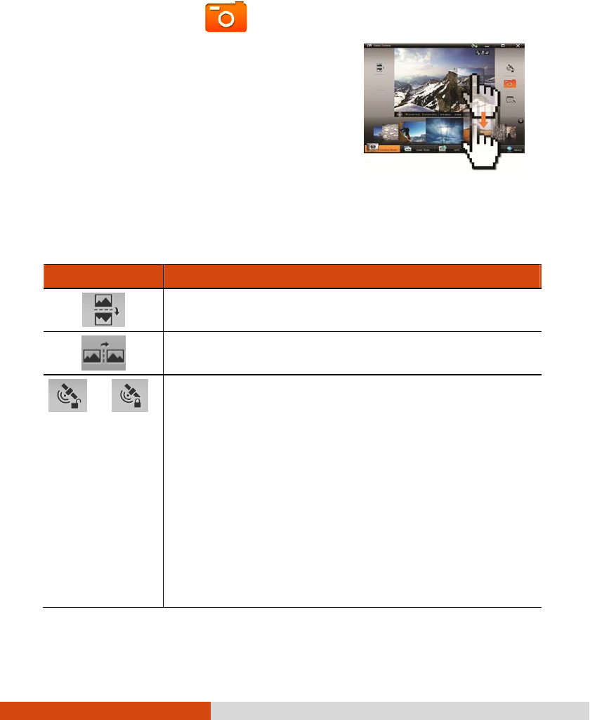
Using Getac Software 6-25
4. When ready, you can shoot the picture in either of the two methods:
Method 1: Tap the button.
Method 2:
Drag the preview image and drop
it into Thumbnail Tray.
5. The picture will appear in the middle of the Thumbnail View and be saved to
the predefined storage location.
Camera Controls Buttons
Camera Controls ButtonsCamera Controls Buttons
Camera Controls Buttons
Control Buttons
Control ButtonsControl Buttons
Control Buttons
Descripti
DescriptiDescripti
Descriptions
onsons
ons
Flips the image vertically.
Flips the image horizontally.
/
Turns on/off GPS lock. The icon in the button shows the current
status.
GPS lock allows you record the exact location of the object
you are shooting instead of where you are using t
he computer
to shoot the picture. First, put the computer near your object
and tap this button to lock the GPS information; then, you
can go farther away to where you can have a good view of
the object for the shooting.
Remember to turn off GPS lock when t
he feature is not needed
for the next picture. The GPS lock is always off whenever
you start the program.
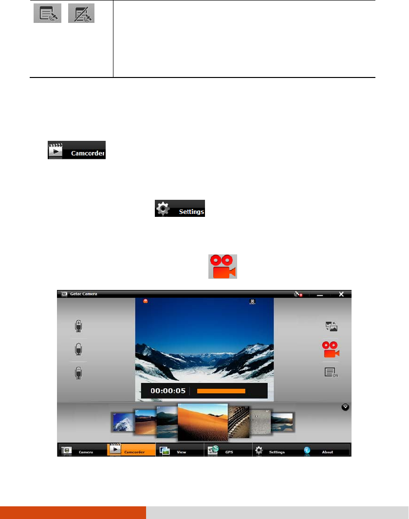
6-26 Using Getac Software
/
Turns off/on watermark. The icon in the button shows the
current status.
You can turn off watermark if you do not want the watermark
to show in
the picture. Your setting remains effective until you
change it again.
Shooting Videos
Shooting VideosShooting Videos
Shooting Videos
1. Start the Getac Camera program. You will be in Camera mode. Tap
to switch to Camcorder mode.
2. You can use the buttons on the right and left side of the preview window for
immediate controls. (See “Camcorder Control Buttons” for detailed information.)
For overall settings, tap . (See “Camera Settings” for detailed
information.)
3. Aim the camera lens at your subject.
To start shooting the video, tap the button.
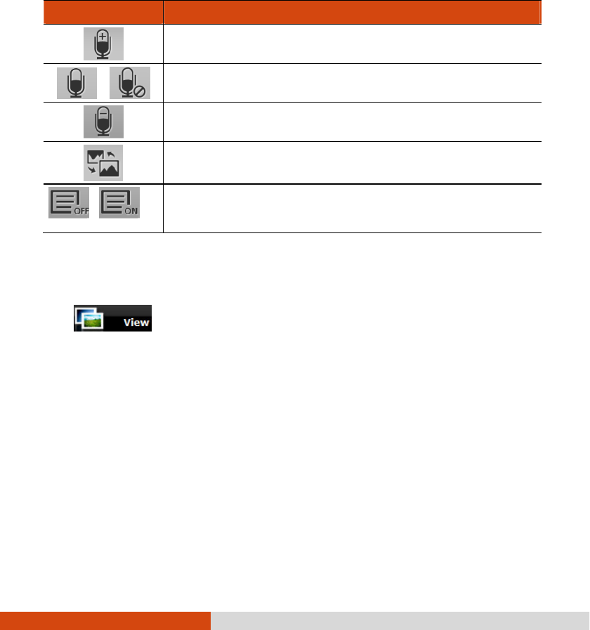
Using Getac Software 6-27
4. To stop, tap the same button again.
5. An image from the video will appear in the middle of the Thumbnail Tray. The
file is saved to the predefined storage location.
Camcorder Control Buttons
Camcorder Control ButtonsCamcorder Control Buttons
Camcorder Control Buttons
Control Buttons
Control ButtonsControl Buttons
Control Buttons
Desc
DescDesc
Descriptions
riptionsriptions
riptions
Increases the recording sound volume.
/
Disables/enables the microphone.
Decreases the recording sound volume.
Flips the image vertically.
/
Turns on/off the display of elapsed recording time and current
volume.
Using View
Using View Using View
Using View Mode
ModeMode
Mode
Tap at the bottom of the screen to switch to View mode.
While in Camera or Camcorder mode, you can also switch to View mode by either
of the two methods:
Method 1: Double-tap the thumbnail in the Thumbnail Tray.
Method 2: Drag the thumbnail and drop into the preview window.
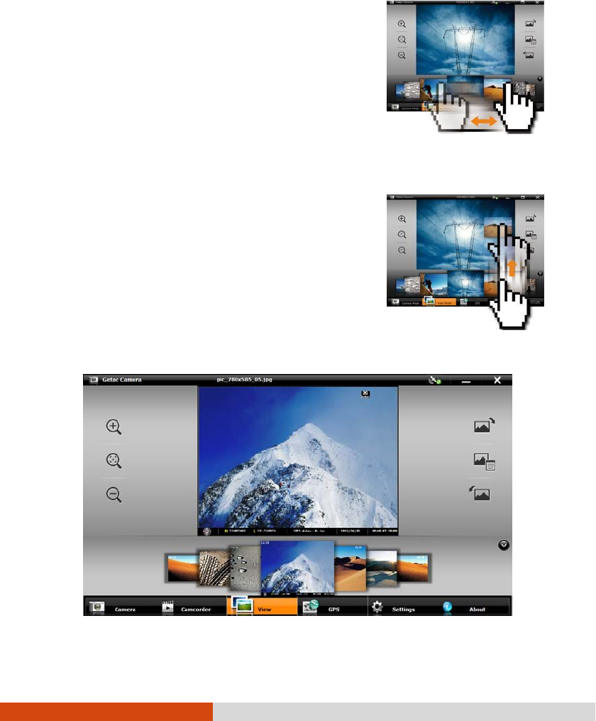
6-28 Using Getac Software
Selecting an Image or Video
Selecting an Image or VideoSelecting an Image or Video
Selecting an Image or Video
To scroll through the Thumbnail Tray, drag the tray
toward the left or right.
To select an image or video, use either of the two
methods:
Method 1: Double-tap the thumbnail in the Thumbnail Tray.
Method 2:
Drag the thumbnail and drop into the
display window.
Image Viewing Controls
Image Viewing ControlsImage Viewing Controls
Image Viewing Controls
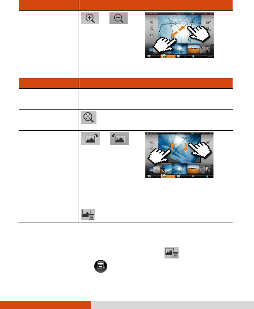
Using Getac Software 6-29
When you select an image to view, you can perform the following tasks.
To
ToTo
To
Via Control Buttons
Via Control ButtonsVia Control Buttons
Via Control Buttons
Via Multi
Via MultiVia Multi
Via Multi-
--
-touch Operations
touch Operationstouch Operations
touch Operations
Zoom in/out
(up to four scales)
/
Drag two fingers apart/
towards to zoom in/out.
To
ToTo
To
Via Control Buttons
Via Control ButtonsVia Control Buttons
Via Control Buttons
Via Multi
Via MultiVia Multi
Via Multi-
--
-touch Operations
touch Operationstouch Operations
touch Operations
When zoomed in, you can drag to view another portion
of the image.
Restore to the 100%
scale
−
Rotate to the right/left
by 90° /
Drag two fingers in a
clockwise/counterclockwise
circular motion.
View image properties
−
Adding Notes to an Image
Adding Notes to an ImageAdding Notes to an Image
Adding Notes to an Image
1. Switch to View mode, select the image, and tap .
2. In properties view, tap .
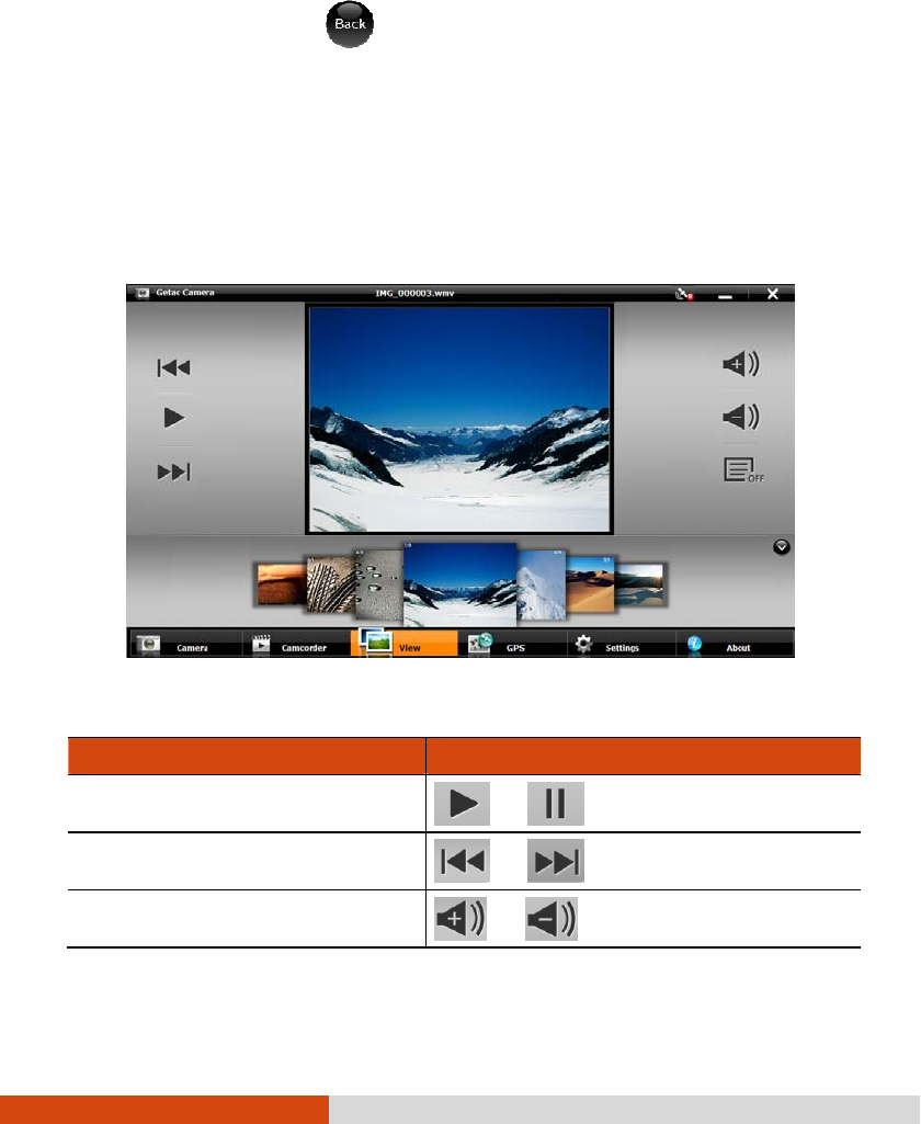
6-30 Using Getac Software
3. Type your notes in the entry field.
4. When completed, tap .
The first three lines of the notes show on the screen.
Video Playback Controls
Video Playback ControlsVideo Playback Controls
Video Playback Controls
When you select a video to playback, you can perform the following tasks.
To
ToTo
To
Via Control Buttons
Via Control ButtonsVia Control Buttons
Via Control Buttons
Start/pause the playback /
Skip backwards/forwards /
Increase/decrease volume /
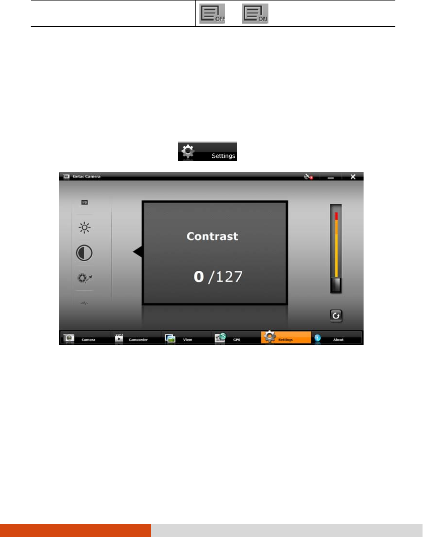
Using Getac Software 6-31
Turn on/off the status display /
Camera Settings
Camera SettingsCamera Settings
Camera Settings
To change camera settings, tap at the bottom of the screen.
Along the left of the window are all the setting items. You can drag this area up
or down to scroll through the items. The middle of the window displays the current
item and setting value. To the right is the adjustment bar where you can tap or
drag to change the setting value.
All changes (except for Camera Mode) remain effective until you change them again.
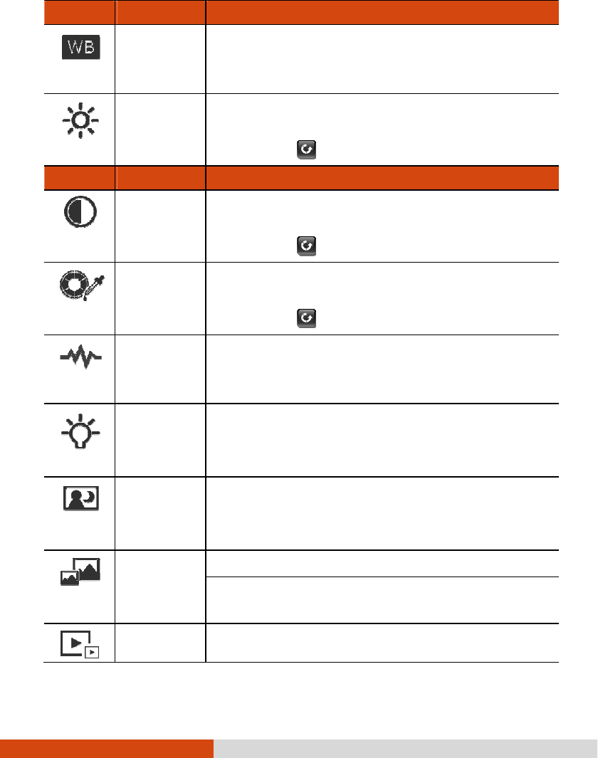
6-32 Using Getac Software
Items
ItemsItems
Items
Name
NameName
Name
Descri
DescriDescri
Descriptions
ptionsptions
ptions
White
Balance
Five choices from which you can select one that matches
the current light source: Automatic (default), Sunshine
,
Cloudy, Fluorescence, and Incandescence.
Brightness
Adjusts the brightness level. The range of levels depends
on computer models.
You can tap to restore to the default level.
Items
ItemsItems
Items
Name
NameName
Name
Descriptions
DescriptionsDescriptions
Descriptions
Contrast
Adjusts the contrast level. The range of levels depends
on computer models.
You can tap to restore to the default level.
Hue Adjusts the hue level. The r
ange of levels depends on
computer models.
You can tap to restore to the default level.
Flicker
Sets the frequency to match the local electrical system
for flicker free shooting under electric light. Choices are:
60Hz (default) and 50Hz.
LED Light Turns On (default) or Off the LED light.
This item is available for setting only on models with the
LED light.
Night Mode Turns On or Off (default) night mode.
You can turn on the feature for shooting in low light
situations.
Image Size Sets the image resolution.
1600 x 1200, 1024 x 768, 800 x 600, or 640 x 480 for
2.0MP Camera.
Video Size Sets the video size to 640x480 or 320x240.
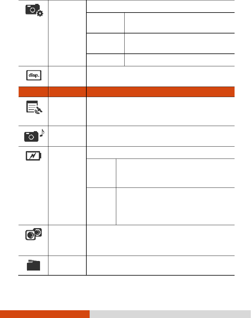
Using Getac Software 6-33
Camera Mode
Three choices for the shooting mode:
Normal
This is the default setting whenever the
program is started.
Continuous Continuous shooting of 3 pictures (one
shot per second).
Timer 5-second countdown before shooting.
Status
Display
Turns On (default) or Off the display of the status
indicators.
Items
ItemsItems
Items
Name
NameName
Name
Descriptions
DescriptionsDescriptions
Descriptions
Watermark Turns On (default) or Off
the display of watermark in the
image. (Turning off does not affect the embedded EXIF
2.2 metadata.)
Shutter
Sound
Turns On (default) or Off
the sound played upon photo
shooting.
Power Saving
Sets if power saving works for the program.
System
(default)
The Camera program enters power saving
mode according to the settings of Windows’
Power Options.
Never The Camera program will not enter power
saving mode while the program window is
open. But when the program window is
minimized, the System setting overrides.
Camera
Switch
Switches to the Front (default) or Bottom camera lens.
The latter is available for selection only on computer
models with two cameras.
Folder Path
Sets the storage location of the images. To change to
a different folder, tap Browse and select the folder.
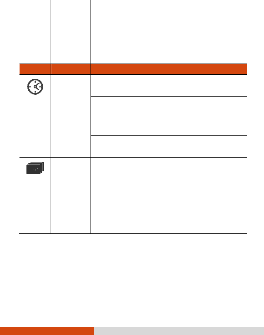
6-34 Using Getac Software
The default location is Users\[user name]\Pictures
folder
that contains the original images. A subfolder named
Thumbs contains a copy of the same images (with
filename prefix Thumb_) for the thumbnail view.
NOTE: If you are adding or deleting images using File
Explorer, make sure to work on both the correct folder
and its Thumbs subfolder.
Items
ItemsItems
Items
Name
NameName
Name
Descriptions
DescriptionsDescriptions
Descriptions
Time Option
Displays the time throughout the program according to one
of the two choices:
System time
zone
(default)
The time zone setting of the computer is
taken into consideration. If the current
location is in daylight saving time, the time
will be adjusted accordingly.
UTC The time is based on Coordinated
Universal Time.
Filename
Prefix
The default filename prefix is IMG
. The complete filename
is IMG_
xxxxxx.
jpg (where
xxxxxx
= sequential number).
When the sequential number has reached 999999 and
you are taking the next picture, a message will pop up
to ask you to change the prefix.
You can change the prefix by typing the characters
(limited to A~Z, a~z, 0~9, -
and _) in the entry field.
Maximum number of characters allowed is 10.

Caring for the Computer 7-1
Chapter 7
Chapter 7Chapter 7
Chapter 7
Caring for the Computer
Caring for the ComputerCaring for the Computer
Caring for the Computer
Taking good care of your computer will ensure a trouble-free operation and reduce
the risk of damage to your computer.
This chapter gives you guidelines covering areas such as protecting, storing, cleaning,
and traveling.

7-2 Caring for the Computer
Protecting the Computer
Protecting the ComputerProtecting the Computer
Protecting the Computer
To safeguard the integrity of your computer data as well as the computer itself, you
can protect the computer in several ways as described in this section.
Using an Anti
Using an AntiUsing an Anti
Using an Anti-
--
-Virus
VirusVirus
Virus
Strategy
StrategyStrategy
Strategy
You can install a virus-detecting program to monitor potential viruses that could damage
your files.
Using Action Center (for Windows 7)
Using Action Center (for Windows 7)Using Action Center (for Windows 7)
Using Action Center (for Windows 7)
Action Center alerts you to take action on the following security essentials:
Windows Firewall
Windows Update
Malware Protection (anti-virus, anti-spyware)
Others (Internet security, user account control)
For detailed information, see Windows’ Help.
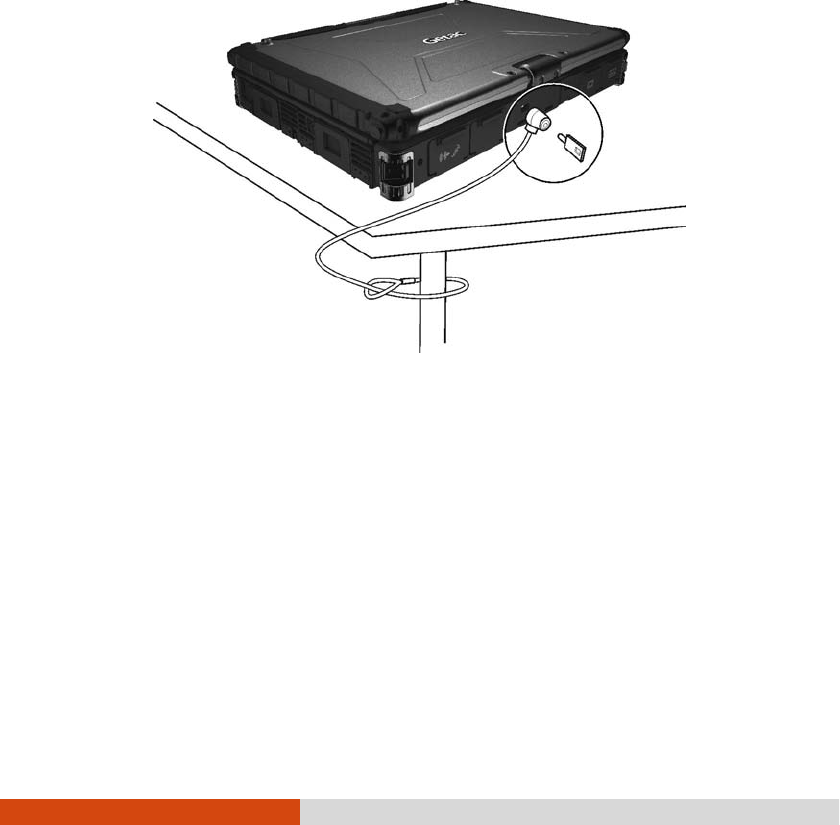
Caring for the Computer 7-3
Using the Cable Lock
Using the Cable LockUsing the Cable Lock
Using the Cable Lock
You can use a Kensington-type cable lock to protect your computer against theft.
The cable lock is available in most computer stores.
To use the lock, loop the lock cable around a stationary object such as a table.
Insert the lock to the Kensington lock hole and turn the key to secure the lock.
Store the key in a safe place.

7-4 Caring for the Computer
Taking Care of the Computer
Taking Care of the ComputerTaking Care of the Computer
Taking Care of the Computer
Loca
LocaLoca
Location
tiontion
tion
Guidelines
GuidelinesGuidelines
Guidelines
For optimal performance, use the computer where the recommended temperature
is between 0°C (32°F) and 55°C (131°F) – actual operating temperature
depending on product specifications.
Avoid placing the computer in a location subject to high humidity, extreme
temperatures, mechanical vibration, direct sunlight, or heavy dust. Using the
computer in extreme environments for long periods can result in product
deterioration and a shortened product life.
Operating in an environment with metallic dust is not allowed.
Place the computer on a flat and steady surface. Do not stand the computer
on its side or store it in an upside-down position. A strong impact by dropping
or hitting may damage the computer.
Do not cover or block any ventilation openings on the computer. For example,
do not place the computer on a bed, sofa, rug, or other similar surface. Otherwise,
overheating may occur that results in damage to the computer.
As the computer can become very hot during operation, keep it away from objects
that are vulnerable to heat.
Keep the computer at least 13 cm (5 inches) away from electrical appliances
that can generate a strong magnetic field such as a TV, refrigerator, motor,
or a large audio speaker.
Avoid moving the computer abruptly from a cold to a warm place. A temperature
difference of more than 10°C (18°F) may cause condensation inside the unit,
which may damage the storage media.

Caring for the Computer 7-5
General Guidelines
General GuidelinesGeneral Guidelines
General Guidelines
Do not place heavy objects on top of the computer when it is closed as this
may damage the display.
The screen surface is easily scratched. Avoid touching it with a sharp object
such as a pen or pencil.
To maximize the life of the backlight in the display, allow the backlight to
automatically turn off as a result of power management. Avoid using a screen
saver or other software that prevents the power management from working.
Cleaning
CleaningCleaning
Cleaning
Guidelines
GuidelinesGuidelines
Guidelines
Never clean the computer with its power on.
Use a soft cloth moistened with water or a non-alkaline detergent to wipe the
exterior of the computer.
Gently wipe the display with a soft, lint-free cloth. Do not use alcohol or detergent
on the display.
Dust or grease on the touchpad can affect its sensitivity. Clean the pad by using
adhesive tape to remove the dust and grease on its surface.
If water or liquid is split onto the computer, wipe it dry and clean when possible.
Though your computer is water-proof, do not leave the computer wet when you
can dry it.
If the computer gets wet where the temperature is 0 °C (32 °F) or below,
freeze damage may occur. Make sure to dry the wet computer.

7-6 Caring for the Computer
Battery Pack
Battery PackBattery Pack
Battery Pack
Guidelines
GuidelinesGuidelines
Guidelines
Recharge the battery pack when it is nearly discharged. When recharging, make
sure that the battery pack is fully charged. Doing so may avoid harm to the
battery pack.
The battery pack is a consumable product and the following conditions will shorten
its life:
– when frequently charging the battery pack
– when using, charging, or storing the battery in high temperature
condition
To avoid hastening the deterioration of the battery pack thereby prolonging its
useful life, minimize the number of times you charge it so as not to frequently
increase its internal temperature.
Charge the battery pack between 10°C ~ 30°C (50°F ~ 86°F) temperature
range.
A higher environment temperature will cause the battery pack’s temperature to
rise. Avoid charging the battery pack inside a closed vehicle and in hot weather
condition.
Also, charging will not start if the battery pack is not within the allowed temperature
range.
It is recommended that you do not charge the battery pack more than once
a day.
It is recommended that you charge the battery pack with the computer’s power
off.
To maintain the battery pack’s operating efficiency, store it in a cool dark place
removed from the computer and with 30% ~ 40% charge remaining.
Important guidelines when using the battery pack.
When installing or removing the battery pack take note of the following:

Caring for the Computer 7-7
– avoid installing or removing the battery pack when the computer is
in Sleep mode. Abruptly removing the battery pack may cause loss
of data or the computer may become unstable.
– avoid touching the battery pack terminals or damage may occur,
thereby causing improper operation to it or the computer.
The computer’s input voltage and surrounding temperature will directly affect the
battery pack’s charge and discharge time:
– charging time will be prolonged when the computer is turned on.
To shorten the charging time, it is recommended that you place the
computer in sleep or hibernation mode.
– a low temperature will prolong the charging time as well as hasten
the discharge time.
When using battery power in an extremely low temperature environment, you may
experience shortened operating time and incorrect battery level reading. This
phenomenon comes from the chemical characteristics of batteries. The appropriate
operating temperature for the battery is -10 °C ~ 50 °C (14 °F ~ 122 °F).
Touchscreen
TouchscreenTouchscreen
Touchscreen
Gui
GuiGui
Guidelines
delinesdelines
delines
Use the finger or the included touchscreen pen on the display. Using a sharp
or metallic object other than your finger or touchscreen pen may cause scratches
and damage the display, thereby causing errors.
Avoid using excessive force that may cause damage to the display.
Use a soft cloth to remove dirt on the display. The touchscreen surface has
a special protective coating that prevents dirt from sticking to it. Not using a
soft cloth may cause damage to the special protective coating on the touchscreen
surface.
Turn off the computer power when cleaning the display. Cleaning the display
with the power on may cause improper operation.

7-8 Caring for the Computer
Do not use excessive force on the display. Avoid moving the computer while
holding the display or twisting the display. Avoid placing objects on top of the
display as this may cause the glass to break thereby damaging the display.
Using the touchscreen during low temperature (less than 5oC) may cause a
slower response time, this is normal. A normal response time may be restored
upon returning to room temperature.
When there is a noticeable discrepancy in the placement of the stylus on the
screen and the indicated position of the onscreen pointer, use the calibration
utility to recalibrate the touchscreen display.

Caring for the Computer 7-9
When Tr
When TrWhen Tr
When Traveling
avelingaveling
aveling
Before traveling with your computer, make a backup of your hard disk data into
flash disks or other storage devices. As an added precaution, bring along an
extra copy of your important data.
Make sure that the battery pack is fully charged.
Make sure that the computer is turned off and the top cover is securely closed.
Do not leave objects in between the keyboard and closed display.
Disconnect the AC adapter from the computer and take it with you. Use the
AC adapter as the power source and as a battery-charger.
Hand-carry the computer. Do not check it in as luggage.
If you need to leave the computer in the car, put it in the trunk of the car
to avoid exposing the computer to excessive heat.
When going through airport security, it is recommended that you send the computer
and flash disks through the X-ray machine (the device you set your bags on).
Avoid the magnetic detector (the device you walk through) or the magnetic wand
(the handheld device used by security personnel).
If you plan to travel abroad with your computer, consult your dealer for the
appropriate AC power cord for use in your country of destination.

Troubleshooting 8-1
Chapter 8
Chapter 8Chapter 8
Chapter 8
Troubleshooting
TroubleshootingTroubleshooting
Troubleshooting
Computer problems can be caused by hardware, software, or both. When you
encounter any problem, it might be a typical problem that can easily be solved.
This chapter tells you what actions to take when solving common computer problems.

8-2 Troubleshooting
Preliminary Checklist
Preliminary ChecklistPreliminary Checklist
Preliminary Checklist
Here are helpful hints to follow before you take further actions when you encounter
any problem:
Try to isolate which part of the computer is causing the problem.
Make sure that you turn on all peripheral devices before turning on the computer.
If an external device has a problem, make sure that the cable connections are
correct and secure.
Make sure that the configuration information is properly set in the BIOS Setup
program.
Make sure that all the device drivers are correctly installed.
Make notes of your observations. Are there any messages on the screen? Do
any indicators light? Do you hear any beeps? Detailed descriptions are useful
to the service personnel when you need to consult one for assistance.
If any problem persists after you follow the instructions in this chapter, contact an
authorized dealer for help.

Troubleshooting 8-3
Solving Common Problems
Solving Common ProblemsSolving Common Problems
Solving Common Problems
Battery Problems
Battery ProblemsBattery Problems
Battery Problems
The battery does not charge (Battery Charge indicator does not light yellow).
Make sure that the AC adapter is properly connected.
Make sure that the battery is not too hot or cold. Allow time for the battery
pack to return to room temperature.
Make sure that the battery pack is installed correctly.
Make sure that the battery terminals are clean.
The operating time of a fully charged battery becomes shorter.
If you often partially recharge and discharge, the battery might not be charged
to its full potential. Initialize the battery to solve the problem.
The battery operating time indicated by the battery meter does not match the
actual operating time.
The actual operating time can be different from the estimated time, depending
on how you are using the computer. If the actual operating time is much less
than the estimated time, initialize the battery.
Bluetooth Problems
Bluetooth ProblemsBluetooth Problems
Bluetooth Problems
I cannot connect to another Bluetooth-enabled device.
Make sure that both devices have activated Bluetooth.
Make sure that the distance between the two devices is within the limit and
that there are no walls or other obstructions between the devices.
Make sure that the other device is not in “Hidden” mode.
Make sure that both devices are compatible.

8-4 Troubleshooting
Display Problems
Display ProblemsDisplay Problems
Display Problems
Nothing appears on the screen.
During operation, the screen may automatically turn off as a result of power
management. Press any key to see if the screen comes back.
The brightness level might be too low. Increase brightness.
The display output might be set to an external device. To switch the display
back to the LCD, press the Fn+F5
Fn+F5Fn+F5
Fn+F5 hot key or change the display through the
settings in Display
DisplayDisplay
Display Properties.
The characters on the screen are dim.
Adjust the brightness and/or contrast.
The display brightness cannot be increased.
As a protection, the display brightness will be fixed at a low level when the
surrounding temperature is too high or too low. It is not a malfunction in this
situation.
Bad dots appear on the display at all times.
A small number of missing, discolored, or bright dots on the screen are an intrinsic
characteristic of TFT LCD technology. It is not regarded as a LCD defect.
Resolution cannot be adjusted to desired setting.
Make sure that the VGA driver is installed correctly.
The external
The external The external
The external monitor displays nothing.
monitor displays nothing.monitor displays nothing.
monitor displays nothing.
Make sure that the monitor is turned on.
Make sure that the monitor’s signal cable is properly connected.
Switch the display to the monitor by pressing the Fn
FnFn
Fn+F5
F5F5
F5 hot key or change the
display through the settings in Display
DisplayDisplay
Display Properties.

Troubleshooting 8-5
Simultaneous display/multi-display does not work.
Make sure that you turn on the external monitor before turning on the computer.
Press the Fn+F5
Fn+F5 Fn+F5
Fn+F5 hot key to toggle through the display options or change the settings
in Display
DisplayDisplay
Display Properties in Windows.
H
HH
Hardware Device Problems
ardware Device Problemsardware Device Problems
ardware Device Problems
The computer does not recognize a newly installed device.
The device may not be correctly configured in the BIOS Setup program. Run
the BIOS Setup program to identify the new type.
Make sure if any device driver needs to be installed. (Refer to the documentation
that came with the device.)
Make sure if the device needs any jumper or switch settings. (Refer to the
documentation that came with the device.)
Check the cables or power cords for correct connections.
For an external device that has its own power switch, make sure that the power
is turned on.
Hard Disk Drive Problems
Hard Disk Drive ProblemsHard Disk Drive Problems
Hard Disk Drive Problems
The hard disk drive error message appears on the screen.
The hard disk drive has defects. Ask your dealer for help.
The hard disk drive operations seem slow.
The data files stored on the hard disk drive may be fragmented. Use a tool
such as Window’s Disk Defragmenter
Disk Defragmenter Disk Defragmenter
Disk Defragmenter to defragment the files.
The hard disk drive in-use indicator glows without blinking.
The data files stored on the hard disk drive may be fragmented. Use a tool
such as Window’s Disk Defragmenter
Disk DefragmenterDisk Defragmenter
Disk Defragmenter to defragment the files.

8-6 Troubleshooting
Keyboard, Mouse, and Touchpad Problems
Keyboard, Mouse, and Touchpad ProblemsKeyboard, Mouse, and Touchpad Problems
Keyboard, Mouse, and Touchpad Problems
The keyboard does not respond.
Try connecting an external keyboard. If it works, contact an authorized dealer,
as the internal keyboard cable might be loose.
Water or liquid is spilt into the keyboard.
Immediately turn off the computer and unplug the AC adapter. Then turn the
keyboard upside down to drain the liquid out of the keyboard. Make sure to
clean up any part of the spill you can get to. Though the keyboard of your
computer is spill-proof, liquid will remain in the keyboard enclosure if you don’t
remove it. Wait for the keyboard to air dry before using the computer again.
The numeric keypad is disabled.
Make sure that the Num Lock
Num LockNum Lock
Num Lock is switched on. (Check if the Num Lock Indicator
glows or not.)
The touchpad does not work, or the pointer is difficult to control with the
touchpad.
Make sure that the touchpad is clean.
LAN Problems
LAN ProblemsLAN Problems
LAN Problems
I cannot access the network.
Make sure that the LAN driver is correctly installed.
Make sure that the LAN cable is properly connected to the RJ-45 connector
and the network hub.
Make sure that the network configuration is appropriate.
Make sure that the user name or password is correct.

Troubleshooting 8-7
Modem Problems
Modem ProblemsModem Problems
Modem Problems
The modem does not work.
Make sure that the modem driver is correctly installed.
Make sure that the telephone line is properly connected.
Make sure that the COM port in the communication software is correctly set.
Turn off power management.
Power Management Problems
Power Management ProblemsPower Management Problems
Power Management Problems
The computer does not enter Sleep or Hibernation mode automatically.
If you have a connection to another computer, the computer does not enter Sleep
or Hibernation mode if the connection is actively in use.
Make sure that the Sleep or Hibernation time-out is enabled.
The computer does not enter Sleep or Hibernation mode immediately.
If the computer is performing an operation, it normally waits for the operation
to finish.
The computer does not resume from Sleep or Hibernation mode.
The computer automatically enters Sleep or Hibernation mode when the battery
pack is empty. Do any one of the following:
− Connect the AC adapter to the computer.
− Replace the empty battery pack with a fully charged one.
The computer does not enter Hibernation mode with the Fn+F12 hot keys.
Make sure that the Hibernation function is specified for the sleep button.
You might be using a PC card that prevents the computer from entering Hibernation
mode. To enter the mode, stop the communication program and then remove
the card or stop the card.

8-8 Troubleshooting
Software Problems
Software ProblemsSoftware Problems
Software Problems
An application program does not work correctly.
Make sure that the software is correctly installed.
If an error message appears on the screen, consult the software program’s
documentation for further information.
If you are sure the operation has stop, reset the computer. (See “Resetting
the Computer” later in this chapter.)
Sound Problems
Sound ProblemsSound Problems
Sound Problems
No sound is produced.
Make sure that the volume control is not set too low.
Make sure that the audio driver is correctly installed.
Make sure that the computer is not in Sleep mode.
If using an external speaker, make sure that the speaker is properly connected.
Distorted sound is produced.
Make sure that the volume control is not set too high or too low. In most cases,
a high setting can cause the audio electronics to distort the sound.
The sound system does not record.
Adjust the playback or recording sound levels.
The external microphone or audio device does not work.
Make sure that the microphone is connected to the proper connector on the
computer.
Make sure that your computer is equipped with the driver needed.
Click the speaker symbol on the taskbar and check the Windows volume control.

Troubleshooting 8-9
Check the volume control of your computer.
Startup Problems
Startup ProblemsStartup Problems
Startup Problems
When you turn on the computer, it does not seem to respond.
Make sure that either the AC adapter is connected or the battery has power.
For models with the HDD heater option: When turning on the computer in an
extremely low temperature environment, the computer will heat up the hard disk
before starting up. The hard disk drive in-use indicator blinks red to indicate
the heater is on. (In conditions where the AC adapter is connected and the
temperature is above an acceptable range, the computer will display messages
on the screen informing you of the heating process; in other conditions, the screen
is simply blank.) Wait till the heating is finished. However, if external AC power
is not available and the remaining battery power is too low for the heating to
complete, the computer may not start up. In case the computer fails to start
up, turn off the computer and leave it in room temperature for about an hour
before trying to turn it on again.
When you turn on the computer, it stops after POST.
Restart your computer.
WLAN Problems
WLAN ProblemsWLAN Problems
WLAN Problems
I cannot use the WLAN feature.
Make sure that the mini PCI-E WLAN card is correctly installed.
Make sure that the necessary driver(s) is correctly installed.
Make sure that the WLAN feature is turned on.
Transmission quality is poor.
Your computer may be in an out-of-range situation. Move your computer closer
to the Access Point or another WLAN device it is associated with.

8-10 Troubleshooting
Check if there is high interference around the environment and solve the problem
as described next.
Radio interference exists.
Move your computer away from the device causing the radio interference such
as microwave oven and large metal objects.
Plug your computer into an outlet on a different branch circuit from that used
by the affecting device.
Consult your dealer or an experienced radio technician for help.
I cannot connect to another WLAN device.
Make sure that the WLAN feature is turned on.
Make sure that the SSID setting is the same for every WLAN device in the
network.
Your computer is not recognizing changes. Restart the computer.
Make sure that the IP address or subnet mask setting is correct.
I cannot communicate with the computer in the network when Infrastructure
mode is configured.
Make sure that the Access Point your computer is associated with is powered
on and all the LEDs are working properly.
If the operating radio channel is in poor quality, change the Access Point and
all the wireless station(s) within the BSSID to another radio channel.
Your computer may be in an out-of-range situation. Move your computer closer
to the Access Point it is associated with.
Make sure that your computer is configured with the same security option
(encryption) to the Access Point.
Use the Web Manager/Telnet of the Access Point to check whether it is connected
to the network.

Troubleshooting 8-11
Reconfigure and reset the Access Point.
I cannot access the network.
Make sure that the necessary driver(s) is correctly installed.
Make sure that the network configuration is appropriate.
Make sure that the user name or password is correct.
You have moved out of range of the network.
Turn off power management.
Other Problems
Other ProblemsOther Problems
Other Problems
The date/time is incorrect.
Correct the date and time via the operating system or BIOS Setup program.
After you have performed everything as described above and still have the incorrect
date and time every time you turn on the computer, the RTC (Real-Time Clock)
battery is at the end of its life. Call an authorized dealer to replace the RTC
battery.

8-12 Troubleshooting
Resetting
ResettingResetting
Resetting
the Computer
the Computerthe Computer
the Computer
You may have to reset (reboot) your computer on some occasions when an error
occurs and the program you are using hangs up.
If the computer operation seems to hang up, first wait. It is possible that the computer
is processing data. Periodically check the hard disk drive in-use indicator, if it flashes
irregularly, the program may be accessing data and preventing you from using the
keyboard. If you are sure the operation has stopped and you cannot use the “restart”
function of the operating system, reset the computer.
Reset the computer by any one of these methods:
Press Ctrl+Alt+Del
Ctrl+Alt+Del Ctrl+Alt+Del
Ctrl+Alt+Del on your built-in keyboard.
Press the Reset button
on the front panel of your computer.
If the above action does not work, press and hold the power button for more
than 5 seconds to force the system to turn off. Then turn on the power again.
CAUTION: Resetting will cause any unsaved data to be lost.
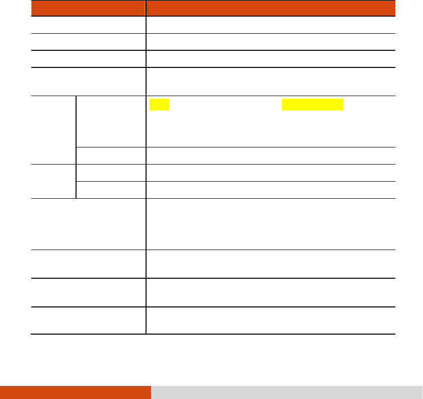
Specifications A-1
Appendix A
Appendix AAppendix A
Appendix A
Specifications
SpecificationsSpecifications
Specifications
NOTE: Specifications are subject to change without any prior notice.
Parts
PartsParts
Parts
Specifications
SpecificationsSpecifications
Specifications
CPU Intel® Ivy Bridge i5-3320M, 2.6G, 35W
Chipset Intel® Panther Point QM77
Memory Up to 8 GB, 240-pin × 2, DDRIII 1333MHz SO-DIMM
BIOS 8 MB EEPROM, system and VGA BIOS, Plug-and-
Play, ACPI 2.0
capability
Display Panel 12.1-inch TFT LCD, resolution up to 1280×800 WXGA
, Touchscreen
function and/or Digitizer feature (option) ,
Sunlight-readable with 1200 nits brightness after touchscreen,
Ultra low brightness (option)
Video controller Integrated in Intel® Ivy Bridge
Audio Features Azalia interface, left/right-channel analog output for line-out connector
Speaker One built-in
Keyboard Standard keys with numeric pad keys, 12 function keys, special Fn
FnFn
Fn
(Function) key and Windows keys
Water-proof and dust-proof membrane, large character printing,
water-proof rubber (option), membrane backlight (option)
Pointing device Glide touchpad with 2 buttons, capacitance-type
Resistive (Glove) touchpad (option)
Hard disk drive SATA 3 interface, 320GB, HDD heater for -20 °C
low temperature
(option), 128GB solid state disk (option)
PC Ca
rd /ExpressCard/Smart
card support
Standard:
ExpressCard/54 + PC card
Option: Smart card + ExpressCard/54
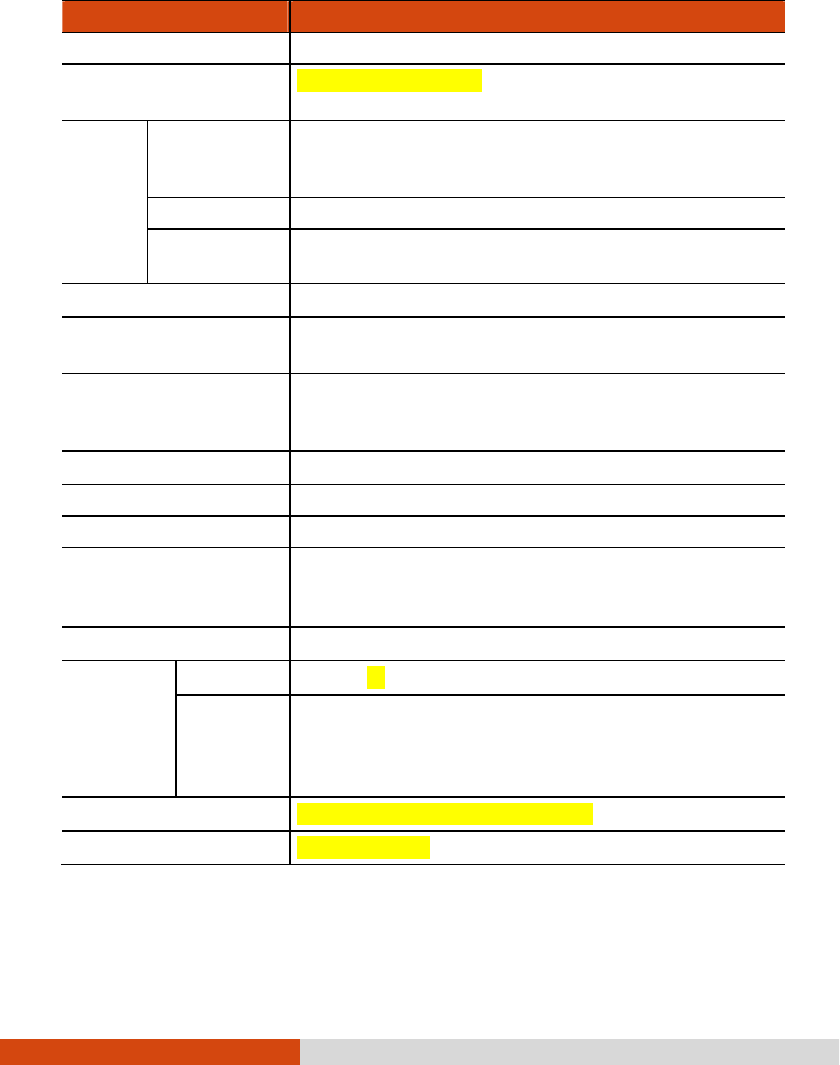
A-2 Specifications
Parts
PartsParts
Parts
Specifications
SpecificationsSpecifications
Specifications
Memory card reader SD/SDHC/SDXC
I/O ports USB 3.0 x 2, USB 2.0, Mini 1394a, serial (RS-232), RJ-
45,
RJ-11, headphone out, microphone, VGA, docking (100-pin)
Antenna Wi-Fi
802.11a/b/g/n +
Bluetooth 2.4G
2 internal (pass-through for external antenna – option)
WCDMA/HSDPA 2 internal (pass-through for external antenna – option)
GPS 1.5G
(option)
1 internal
Modem Azalia interface, 56 Kbps, ITU V.90 MDC 1.5 internal fax modem
LAN IEEE 802.3i 10Base-T, IEEE 802.3u 100Base-T, IEEE 802.3ab
1000Base-T Ethernet
Wireless LAN + Bluetooth Intel® Centrino Advanced-N 6235, 802.11 a/b/g/n
WLAN booster (option)
Blutooth 4.0 class 1 + EDR
Camera 2M pixel (EDOF), 225-degree rotation
GPS (option) EB-5318RF
WWAN (option) WCDMA/HSDPA
Security Kensington lock
TPM 1.2
Fingerprint scanner (option)
Handle Grip and cross-type hand strap
Power AC adapter Universal 90 W; input: 100∼240 V, 50/60 Hz; output: 19 V
Battery Li-ion smart 9-cell battery 8700 mAH / 10.8 V
Li-ion smart 6-cell battery 6140 mAH / 10.8V (option)
user-swappable, under -20 oC combined with hard drive low
temperature solution
Dimension (L×W×H) 314×227×49 mm (12.4×8.74×1.93 inch)
Weight 2.8 kg (5.95 lb)

Specifications A-3
Parts
PartsParts
Parts
Specifications
SpecificationsSpecifications
Specifications
Environment Temperature Operating: 0 °C (32 °F) to 60 °C (140 °F)
-20 °C (-4 °F) to 60 °C (140 °F) –
low temperature
option
Non-operating: -51 °C (-60 °F) to 71 °C (160 °F)
Humidity 5 % to 95 % relative, non-condensing
Altitude Operating: 15,000 ft
Non-operating: 40,000 ft
Shock Operating: 40 g, 11 ms, sawtooth pulse
Environment Vibration Integrity: MIL-STD-810G, Method 514.6, E-1, Category 24,
minimum integrity
Vehicle: MIL-STD-810G, Method 514.6, C-1, Category 4, Secured
Cargo
MIL-STD-810G, Method 514.6, C-1, Category 20,
Ground Vehicle
Drop 100 cm drop 26 times onto plywood plate surface
Enclosure IP65 (with input/output doors closed)
ESD Air discharge: 0~8 KV (included) no error; 9~15 KV allow soft error
Contact discharge: 0~6 KV (included) no error; 7~8 KV allow soft
error
Regulation EMC FCC part 15, subpart B, class B, CE, CCC
Safety UL, TUV, TUV/CB, E-mark
Green Product
Coverage
RoHS 6 European union banned materials, EPEAT
Other 12 universal GP product banned materials, ENERGY STAR, WEEE

Regulatory Information B-1
Appendix B
Appendix BAppendix B
Appendix B
Regulatory Information
Regulatory InformationRegulatory Information
Regulatory Information
This appendix provides regulatory statements and safety notices on your computer.
NOTE: Marking labels located on the exterior of your computer indicate the
regulations that your model complies with. Please check the marking labels and
refer to the corresponding statements in this appendix. Some notices apply to
specific models only.

B-2 Regulatory Information
On the Use of the System
On the Use of the SystemOn the Use of the System
On the Use of the System
Class B Regulations
Class B RegulationsClass B Regulations
Class B Regulations
USA
USAUSA
USA
Federal Communications Commission Radio Frequency Interference Statement
NOTE:
NOTE:NOTE:
NOTE:
This equipment has been tested and found to comply with the limits for a Class
B digital device pursuant to Part 15 of the FCC Rules. These limits are designed
to provide reasonable protection against harmful interference in a residential installation.
This equipment generates, uses, and can radiate radio frequency energy and, if not
installed and used in accordance with the instructions, may cause harmful interference
to radio communications. However, there is no guarantee that interference will not
occur in a particular installation. If this equipment does cause harmful interference
to radio or television reception, which can be determined by turning the equipment
off and on, the user is encouraged to try to correct the interference by one or more
of the following measures:
Reorient or relocate the receiving antenna.
Increase the separation between the equipment and receiver.
Connect the equipment into an outlet on a circuit different from that to which
the receiver is connected.
Consult the dealer or an experienced radio/TV technician for help.
Any changes or modifications not expressly approved by the manufacturer could void
the user’s authority to operate the equipment.
Please note:
Please note:Please note:
Please note:
The use of a non-shielded interface cable with this equipment is prohibited.

Regulatory Information B-3
Canada
CanadaCanada
Canada
Canadian Department of Communications
Radio Interference Regulations Class B Compliance Notice
This Class B digital apparatus meets all requirements of the Canada
Interference-Causing equipment regulations.
Cet appareil numérique de Classe B respecte toutes les exigences du Règlement
Canadien sur le matériel brouileur.
This digital apparatus does not exceed the Class B limits for radio noise emissions
from digital apparatus set out in the Radio Interference Regulations of the Canadian
Department of Communications.
Le présent appareil numérique n’émet pas de bruits radioélectriques dépassant les
limites applicables aux appareils numériques de la classe B prescrites dans le
Règlement sur le brouillage radioélectrique édicté par le ministère des Communications
du Canada.
UL1604
UL1604UL1604
UL1604
Installation Instructions
Installation InstructionsInstallation Instructions
Installation Instructions
This equipment is suitable for use in Class I, Division 2, Groups A, B, C and
D OR non-hazardous locations only.
WARNING – EXPLOSION HAZARD – Do not disconnect equipment unless power
has been removed or the area is known to be non-hazardous.
WARNING – EXPLOSION HAZARD - Substitution of components may impair
suitability for Class I, Division 2.
Non-LPS or TNV output connectors identify the type of circuit, intended cable
type or relevant circuit characteristics.
"IMPORTANT SAFETY INSTRUCTIONS - When using your telephone equipment,
basic safety precautions should always be followed to reduce the risk of fire,
electric shock and injury to persons, including the following:
− Do not use this product near water for example, near a bathtub,

B-4 Regulatory Information
washbowl, kitchen sink or laundry tub, in a wet basement or near a
swimming pool.
− Avoid using a telephone (other than a cordless type) during an electrical
storm. There may be a remote risk of electric shock from lightning.
− Do not use the telephone to report a gas leak in the vicinity of the leak.
Use only the power cord and batteries indicated in this manual. Do not dispose
of batteries in a fire. They may explode. Check with local codes for possible
special disposal instructions.
“SAVE THESE INSTRUCTIONS"
Safety Notices
Safety NoticesSafety Notices
Safety Notices
About the Battery
About the BatteryAbout the Battery
About the Battery
Caution Texts Concerning Lithium Batteries
DANISH
ADVARSEL! Lithiumbatteri – Eksplosionsfare ved fejlagtig håndtering. Udskiftning må
kun ske med batteri af samme fabrikat og type. Levér det brugte batteri tilbage til
leverandøren.
NORWEGIAN
ADVARSEL: Eksplosjonsfare ved feilaktig skifte av batteri. Benytt samme batteritype
eller en tilsvarende type anbefalt av apparatfabrikanten. Brukte batterier kasseres i
henhold til fabrikantens instruksjoner.
SWEDISH
VARNING: Explosionsfara vid felaktigt batteribyte. Använd samma batterityp eller en
ekvivalent typ som rekommenderas av apparattillverkaren. Kassera använt batteri enligt
fabrikantens instruktion.
FINNISH
VAROITUS: Paristo voi räjähtää, jos se on virheellisesti asennettu. Vaihda paristo

Regulatory Information B-5
ainoastaan valmistajan suosittelemaan tyyppiin. Hävitä käytetty paristo valmistajan
ohjeiden mukaisesti.
ENGLISH
CAUTION: Danger of explosion if battery is incorrectly replaced. Replace only with
the same or equivalent type recommended by the equipment manufacturer. Discard
used batteries according to manufacturer's instructions.
DEUTSCH
VORSICHT: Explosionsgefahr bei unsachgemäßem Austausch der Batterie. Ersatz nur
durch denselben oder einen vom Hersteller empfohlenen gleich-wertigen Typ.
Entsorgung gebrauchter Batterien nach Angaben des Herstellers.
FRENCH
ATTENTION: II y a danger d’explosion s’il y a remplacement incorrect de la batterie.
Remplacer uniquement avec une batterie du même type ou d’un type équivalent
recommandé par le constructeur. Mettre au rebut les batteries usagées conformément
aux instructions du fabricant.
Attention (for USA Users)
The product that you have purchased contains a rechargeable battery. The battery
is recyclable. At the end of its useful life, under various state and local laws, it
may be illegal to dispose of this battery into the municipal waste stream. Check
with your local solid waste officials for details in your area for recycling options or
proper disposal.
About the AC Adapter
About the AC AdapterAbout the AC Adapter
About the AC Adapter
Use only the AC adapter supplied with your computer. Use of another type of
AC adapter will result in malfunction and/or danger.
Do not use the adapter in a high moisture environment. Never touch the adapter
when your hands or feet are wet.
Allow adequate ventilation around the adapter when using it to operate the device
or charge the battery. Do not cover the AC adapter with paper or other objects

B-6 Regulatory Information
that will reduce cooling. Do not use the AC adapter while it is inside a carrying
case.
Connect the adapter to a proper power source. The voltage requirements are
found on the product case and/or packaging.
Do not use the adapter if the cord becomes damaged.
Do not attempt to service the unit. There are no serviceable parts inside. Replace
the unit if it is damaged or exposed to excess moisture.
About the Modem
About the ModemAbout the Modem
About the Modem
Caution
Never install telephone wiring during a lightning storm.
Never install telephone jacks in wet locations unless the jack is specifically designed
for wet locations.
Never touch non-insulated telephone wires or terminals unless the telephone line
has been disconnected at the network interface.
Use caution when installing or modifying telephone lines.
Avoid using the telephone function (other than a cordless type) during an
electrical storm. There may be a remote risk of electric shock from lightning.
Do not use the telephone function to report a gas leak in the vicinity of the
leak.
Do not use this product near water, for example near a bathtub, wash bowl,
kitchen sink or laundry tub, in a wet basement or near a swimming pool.
Caution (for USA Users)
To reduce the risk of fire, use only No.26 AWG or larger telecommunication line
cord.

Regulatory Information B-7
On t
On tOn t
On the Use of the RF Device
he Use of the RF Devicehe Use of the RF Device
he Use of the RF Device
NOTE: The information in this section applies to models with the wireless LAN
module.
USA and Canada Safety Requirements and Notices
USA and Canada Safety Requirements and NoticesUSA and Canada Safety Requirements and Notices
USA and Canada Safety Requirements and Notices
IMPORTANT NOTE:
IMPORTANT NOTE:IMPORTANT NOTE:
IMPORTANT NOTE: To comply with FCC RF exposure compliance requirements, the
antenna used for this transmitter must be installed to provide a separation distance
of at least 20 cm from all persons and must not be co-located or operating in
conjunction with any other antenna or transmitter.
Radio Frequency
Radio FrequencyRadio Frequency
Radio Frequency
Interference R
Interference RInterference R
Interference Requirements and SAR
equirements and SARequirements and SAR
equirements and SAR
The FCC with its action in ET Docket 93-62 has adopted a safety standard for
human exposure to Radio Frequency (RF) electromagnetic energy emitted by FCC
certified equipment. The wireless LAN module meets the Human Exposure limits found
in OET Bulletin 65, 2001, and ANSI/IEEE C95.1, 1992. Proper operation of this
radio according to the instructions found in this manual will result in exposure
substantially below the FCC’s recommended limits. The following safety precautions
should be observed:
Do not touch or move antenna while the unit is transmitting or receiving.
Do not hold any component containing the radio such that the antenna is very
close or touching any exposed parts of the body, especially the face or eyes,
while transmitting.
Do not operate the radio or attempt to transmit data unless the antenna is
connected; if not, the radio may be damaged.
Use in specific environments:
The use of wireless devices in hazardous locations is limited by the constraints
posed by the safety directors of such environments.

Regulatory Information B-9
EMC Requirements
This device uses, generates and radiates radio frequency energy. The radio frequency
energy produced by this device is well below the maximum exposure allowed by
the Federal Communications Commission (FCC).
This device complies with the limits for a Class B digital device pursuant to Part
15 subpart C of the FCC Rules and Regulations. Operation is subject to the following
two conditions:
(1) This device may not cause harmful interference.
(2) This device must accept any interference received, including interference that
may cause undesired operation.
The FCC limits are designed to provide reasonable protection against harmful
interference when the equipment is installed and used in accordance with the instruction
manual and operated in a commercial environment. However, there is no guarantee
that interference will not occur in a particular commercial installation, or if operated
in a residential area.
If harmful interference with radio or television reception occurs when the device is
turned on, the user must correct the situation at the user’s own expense. The user
is encouraged to try one or more of the following corrective measures:
Reorient or relocate the receiving antenna.
Increase the separation between the equipment and receiver.
Connect the equipment into an outlet on a circuit different from that to which
the receiver is connected.
Consult the dealer or an experienced radio/TV technician for help.
CAUTION:
CAUTION: CAUTION:
CAUTION: The Part 15 radio device operates on a non-interference basis with other
devices operating at this frequency. Any changes or modification to said product not
expressly approved by the manufacturer could void the user’s authority to operate
this device.

B-10 Regulatory Information
Canada Radio Frequency Interference Requirements
Canada Radio Frequency Interference RequirementsCanada Radio Frequency Interference Requirements
Canada Radio Frequency Interference Requirements
To prevent radio interference to the licensed service, this device is intended to be
operated indoors and away from windows to provide maximum shielding. Equipment
(or its transmit antenna) that is installed outdoors is subject to licensing.
Pour empêcher que cet appareil cause du brouillage au service faisant l'objet d'une
licence, il doit être utilisé à l'intérieur et devrait être placé loin des fenêtres afin
de fournir un écran de blindage maximal. Si le matériel (ou son antenne d'émission)
est installé à l'extérieur, il doit faire l'objet d'une licence.
European Union CE Marking and Compliance
European Union CE Marking and Compliance European Union CE Marking and Compliance
European Union CE Marking and Compliance
Notices
NoticesNotices
Notices
Statements of Compliance
Statements of ComplianceStatements of Compliance
Statements of Compliance
English
EnglishEnglish
English
This product follows the provisions of the European Directive 1999/5/EC.
Danish
DanishDanish
Danish
Dette produkt er i overensstemmelse med det europæiske direktiv 1999/5/EC.
Dutch
DutchDutch
Dutch
Dit product is in navolging van de bepalingen van Europees Directief 1999/5/EC.
Finnish
FinnishFinnish
Finnish
Tämä tuote noudattaa EU-direktiivin 1999/5/EC määräyksiä.
French
FrenchFrench
French
Ce produit est conforme aux exigences de la Directive Européenne 1999/5/EC.
German
GermanGerman
German
Dieses Produkt entspricht den Bestimmungen der Europäischen Richtlinie 1999/5/EC.
Greek
GreekGreek
Greek
To προϊόν αυτό πληροί τις προβλέψεις της Ευρωπαϊκής Οδηγίας
1999/5/EC.

Regulatory Information B-11
Icelandic
IcelandicIcelandic
Icelandic
Þessi vara stenst reglugerð Evrópska Efnahags Bandalagsins númer 1999/5/EC.
Italian
ItalianItalian
Italian
Questo prodotto è conforme alla Direttiva Europea 1999/5/EC.
Norwegian
NorwegianNorwegian
Norwegian
Dette produktet er i henhold til bestemmelsene i det europeiske direktivet 1999/5/EC.
Portuguese
PortuguesePortuguese
Portuguese
Este produto cumpre com as normas da Diretiva Européia 1999/5/EC.
Spanish
SpanishSpanish
Spanish
Este producto cumple con las normas del Directivo Europeo 1999/5/EC.
Swedish
SwedishSwedish
Swedish
Denna produkt har tillverkats i enlighet med EG-direktiv 1999/5/EC.
Local Restrictions of 802.11a/g/n Radio
Local Restrictions of 802.11a/g/n RadioLocal Restrictions of 802.11a/g/n Radio
Local Restrictions of 802.11a/g/n Radio
Usage
UsageUsage
Usage
CAUTION:
CAUTION:CAUTION:
CAUTION: Due to the fact that the frequencies used by 802.11a/g/n wireless LAN
devices may not yet be harmonized in all countries, 802.11a/g/n products are
designed for use only in specific countries or regions, and is not allowed to be operated
in countries or regions other than those of designated use. As a user of these products,
you are responsible for ensuring that the products are used only in the countries
or regions for which they were intended and for verifying that they are configured
with the correct selection of frequency and channel for the country or region of use.
Any deviation from permissible settings and restrictions in the country or region of
use could be an infringement of local law and may be punished as such.
The European variant is intended for use throughout the European Economic Area.
However, authorization for use is further restricted in particular countries or regions
within countries, as follows:

B-12 Regulatory Information
General
European standards dictate maximum radiated transmit power of
100 mW Effective Isotropic Radiated Power (EIRP) and the frequency range 2400
– 2483.5 MHz.
Belgium and the Netherlands
In Belgium and the Netherlands, the product may not be used outdoors. See the
instructions next under the heading “Turning Off the Wireless LAN Radio”.
France
Departments in Which the Wireless LAN Module Can Be Used (Indoors Only)
The wireless LAN module can currently be used indoors only in the following 38
departments of mainland France. Please turn off your wireless LAN radio when
operating the device in areas/places other than the 38 departments listed:
01 Ain Orientales 36
Indre 66
Pyrénées
02
Aisne 37
Indre et Loire 67
Bas Rhin
03
Allier 41
Loir et Cher 68
Haut Rhin
05
Hautes Alpes 42
Loire 70
Haute Saône
08
Ardennes 45
Loiret 71
Saône et Loire
09
Ariège 50
Manche 75
Paris
11 Aude 55
Meuse 82
Tarn et Garonne
12 Aveyron 58
Nièvre 84
Vaucluse
16 Charente 59
Nord 88
Vosges
24
Dordogne 60
Oise 89
Yonne
25
Doubs 61
Orne 90
Territoire de Belfort
26
Drôme 63
Puy du Dôme 94
Val de Marne
32
Gers 64
Pyrénées Atlantique

Regulatory Information B-13
Departments in Which the Wireless LAN Module’s Maximum EIRP Not Shown in the
Previous Table
Frequency Ranges
Frequency Ranges Frequency Ranges
Frequency Ranges
(MHz)
(MHz)(MHz)
(MHz)
Indoors
IndoorsIndoors
Indoors
Outdoors
OutdoorsOutdoors
Outdoors
2400 – 2446.5 10 mW Not permitted
2446.5 – 2483.5 100 mW
100 mW on private property with Ministry of
Defense approval
Turning Off the Wireless LAN Radio
Turning Off the Wireless LAN RadioTurning Off the Wireless LAN Radio
Turning Off the Wireless LAN Radio
N
NN
NOTE:
OTE: OTE:
OTE: Turning the wireless LAN radio off is not the same as disabling the wireless
LAN card. It is not necessary to disable the card to meet the regulatory requirements.
While operating the computer in those French departments that do not allow use
of the wireless LAN equipment, the user of the equipment must turn off the wireless
LAN radio in order to comply with local regulations.