Getac Technology 6235 WLAN/BT Module User Manual
Getac Technology Corporation WLAN/BT Module
UserManual.wiki
>
Getac Technology
>
6235 User Manual
User Manual
Navigation menu
Upload a User Manual
Namespaces
Wiki Guide
HTML
PDF
Info
Views
User Manual
Discussion / Help
Navigation
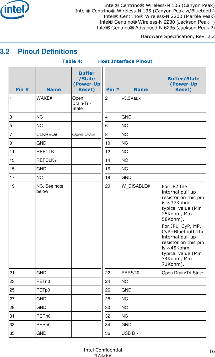
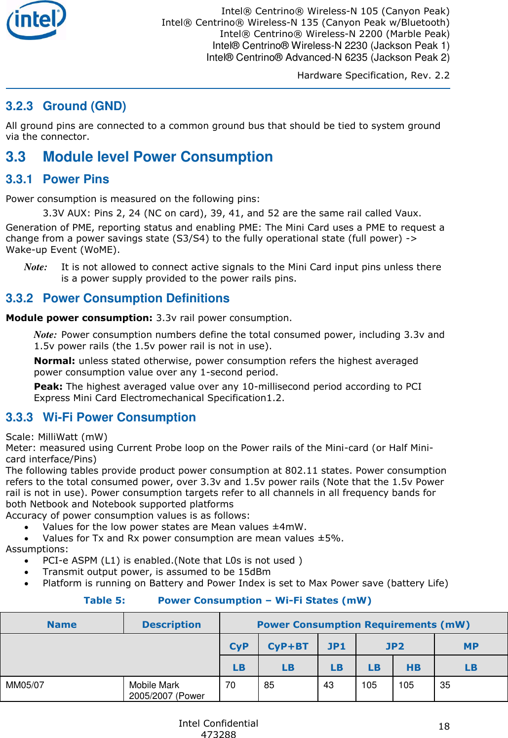
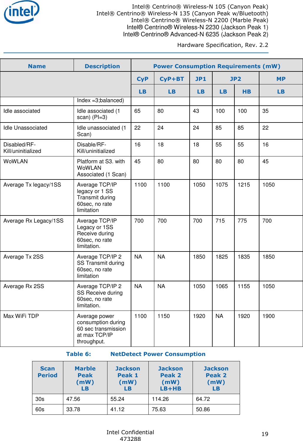
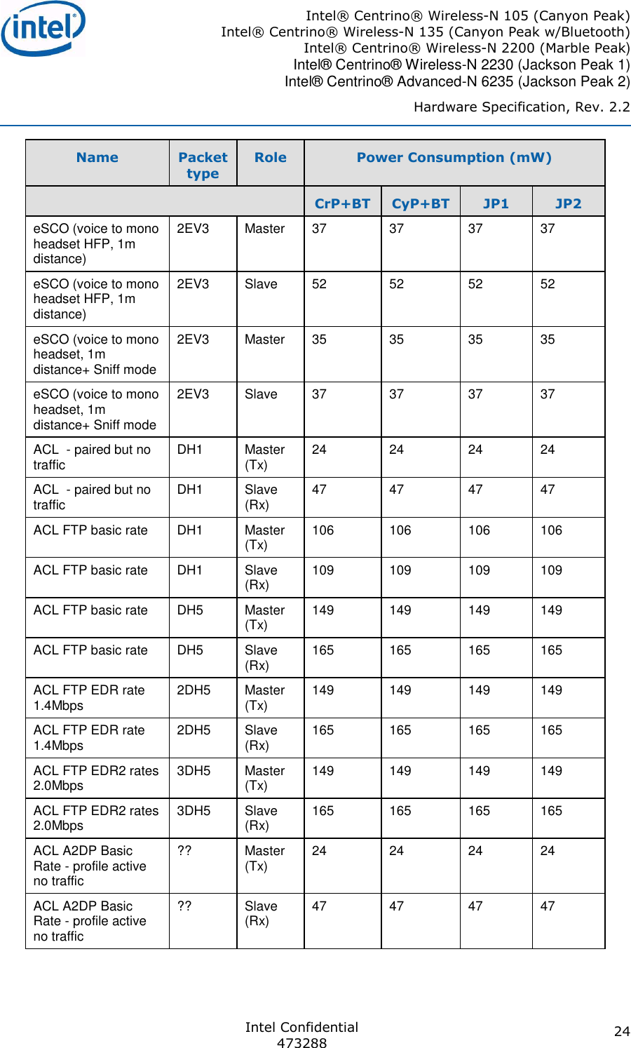
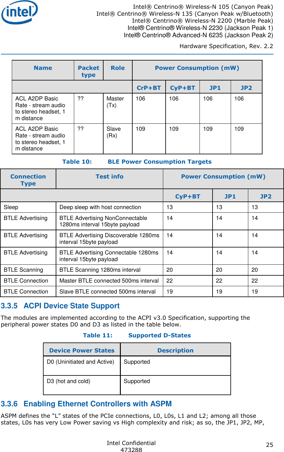
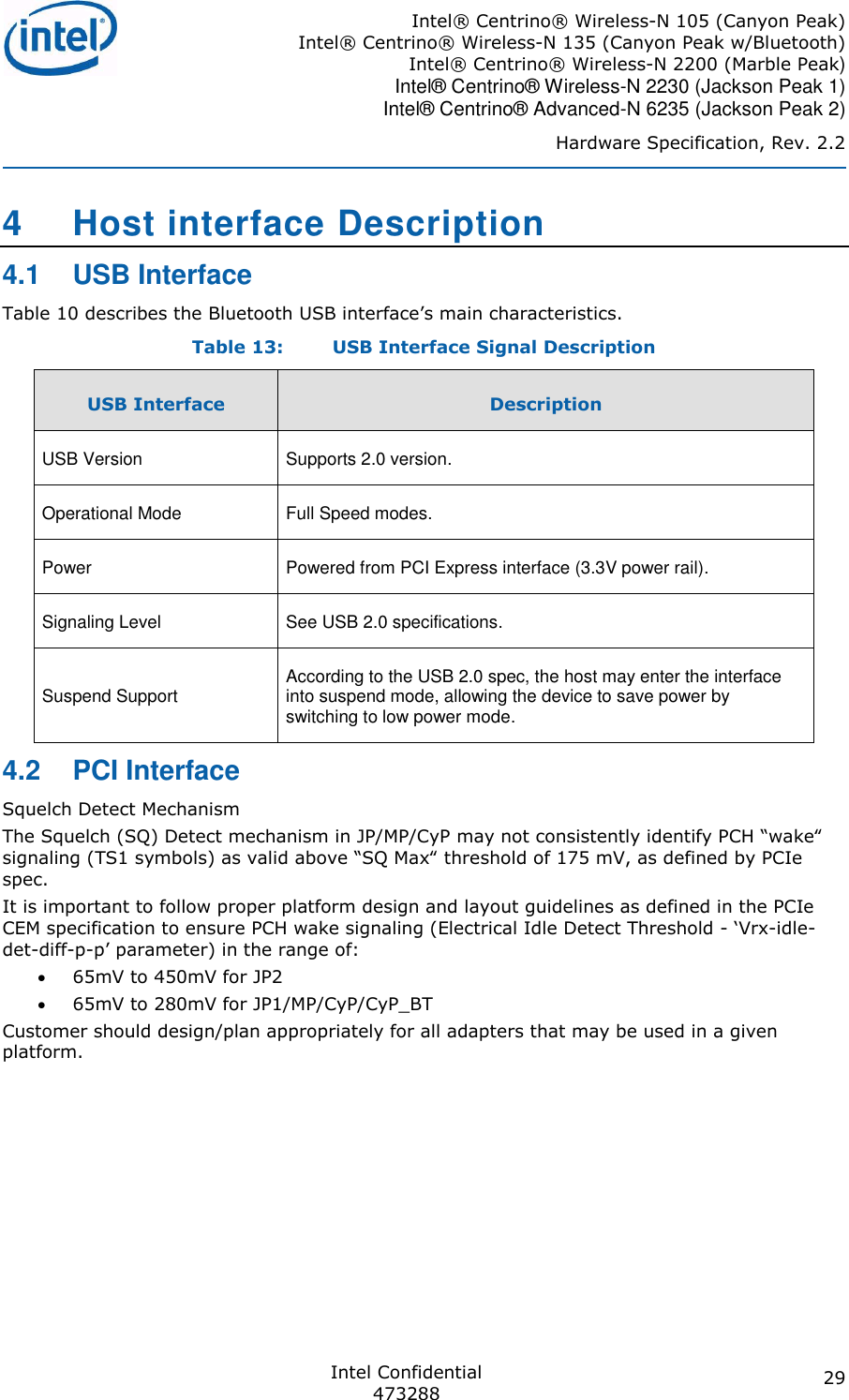
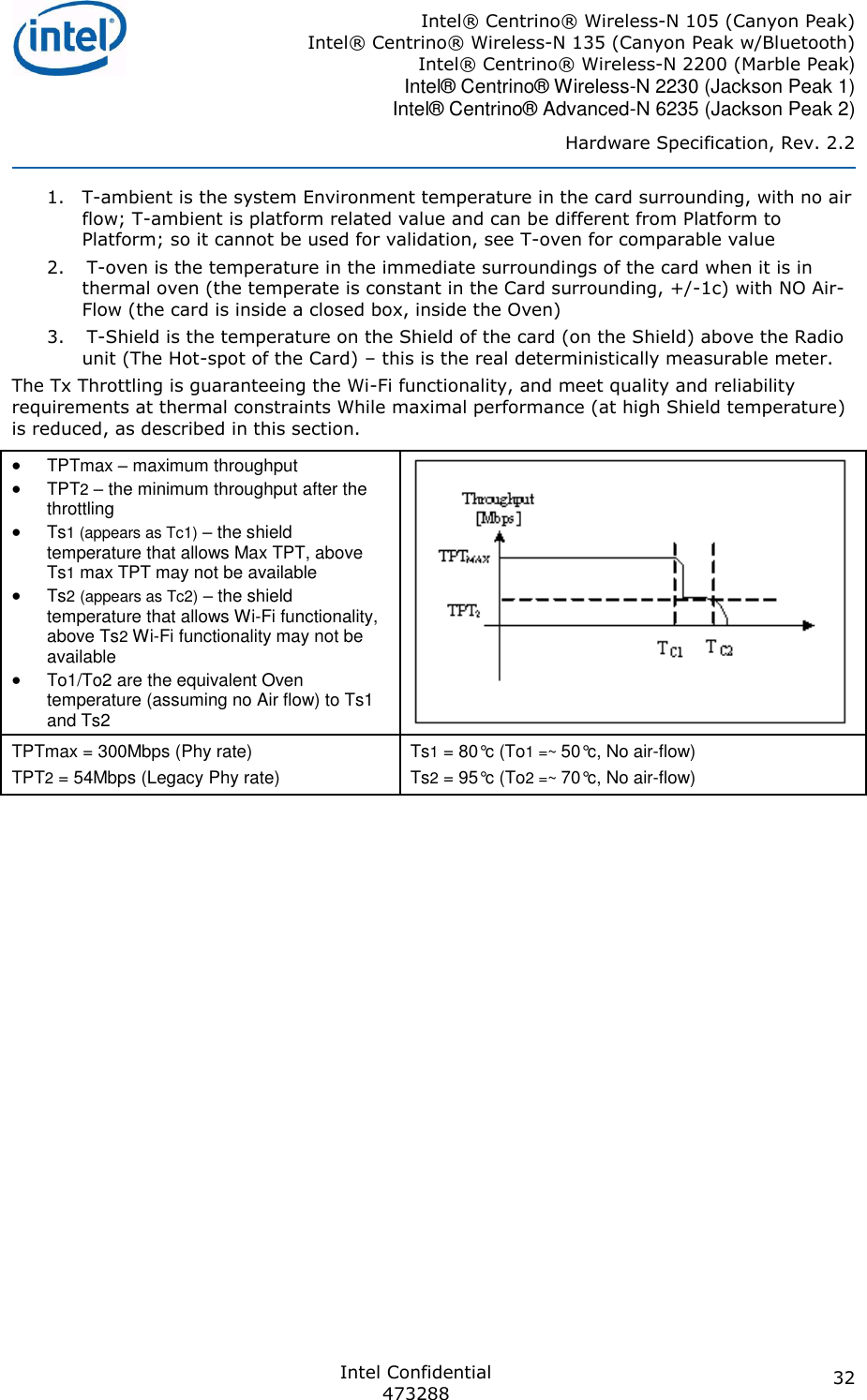
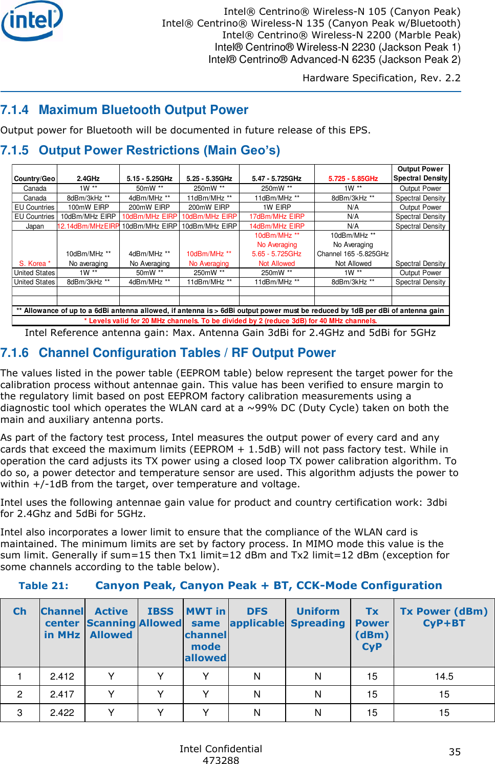
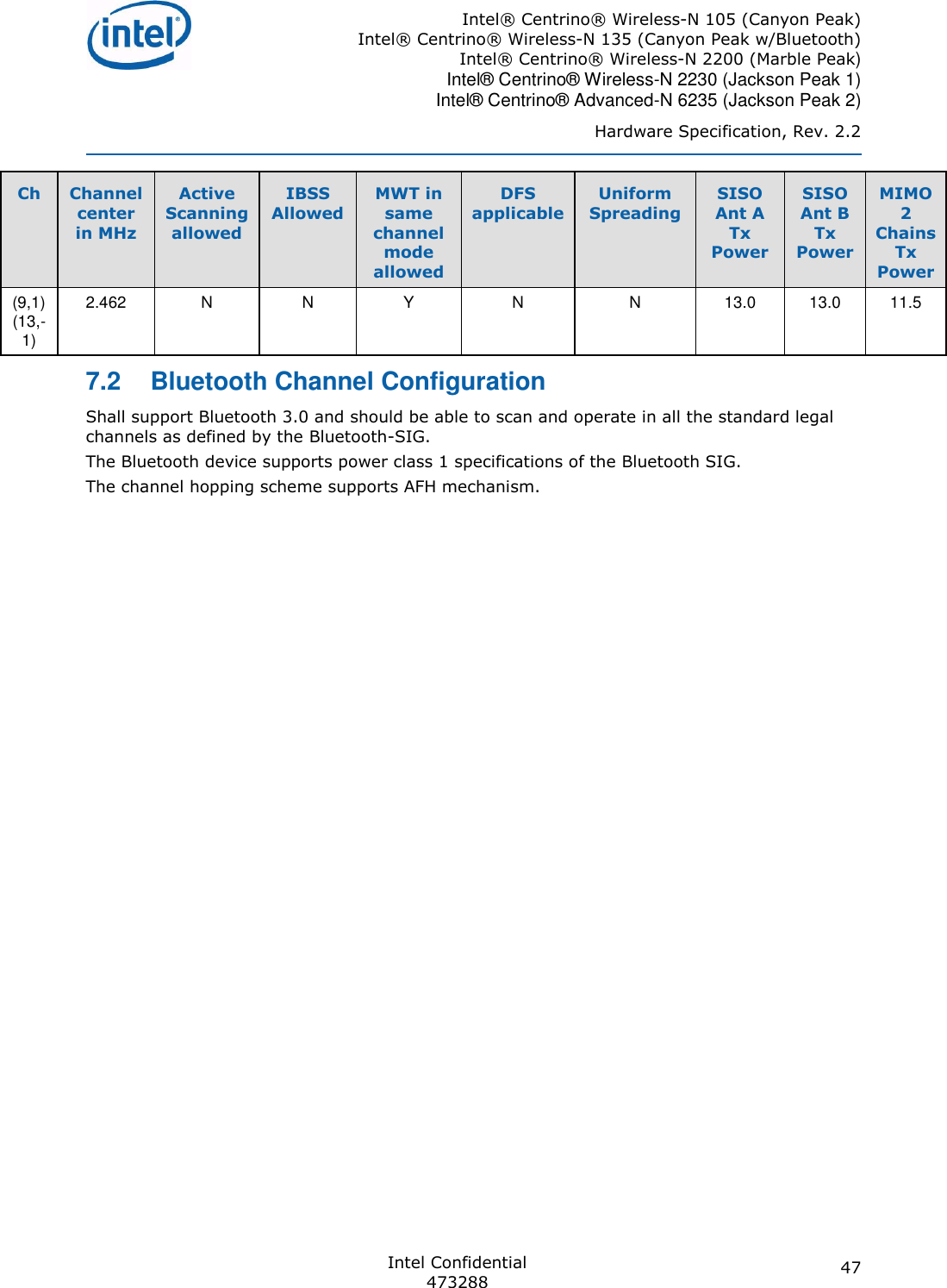
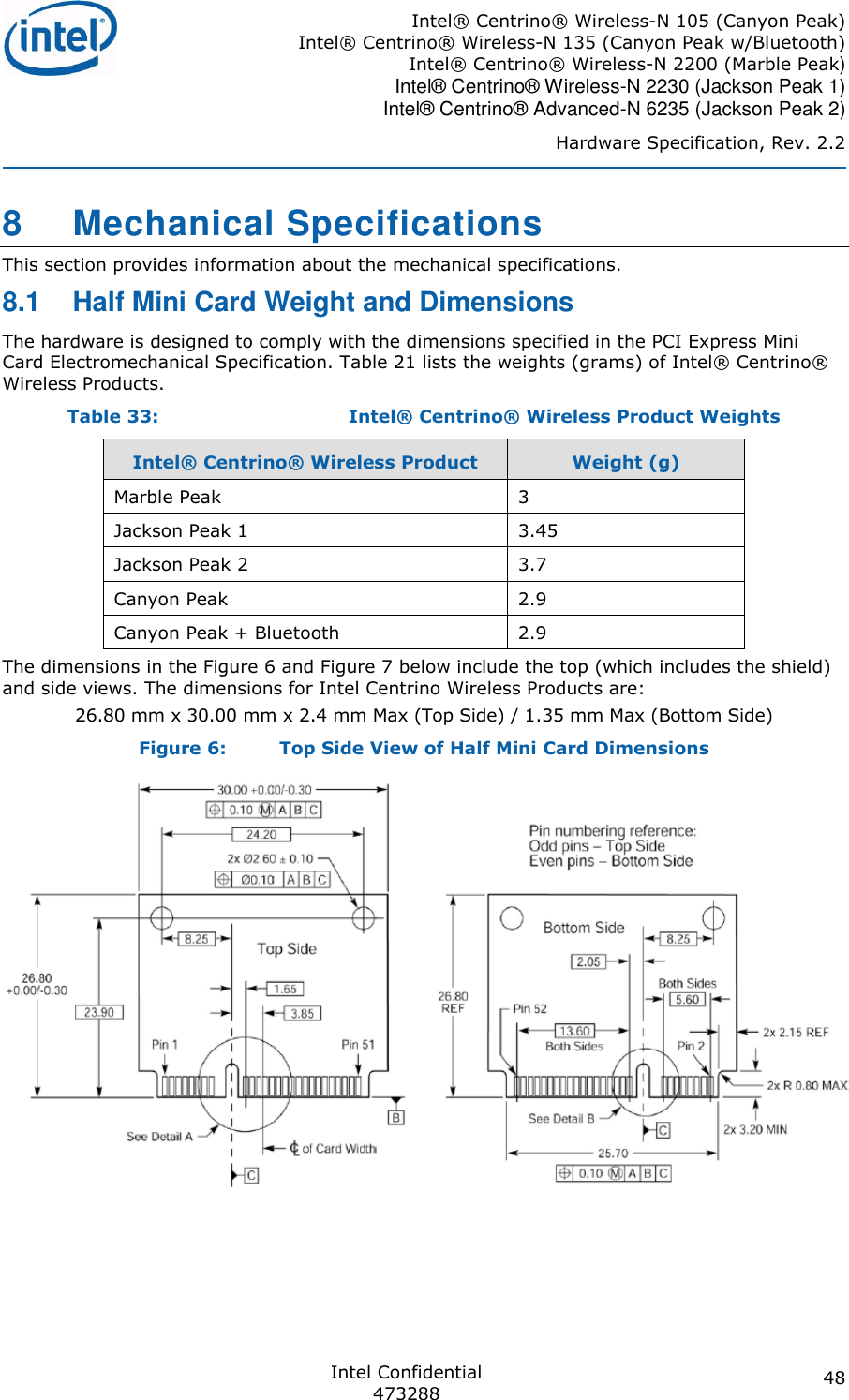
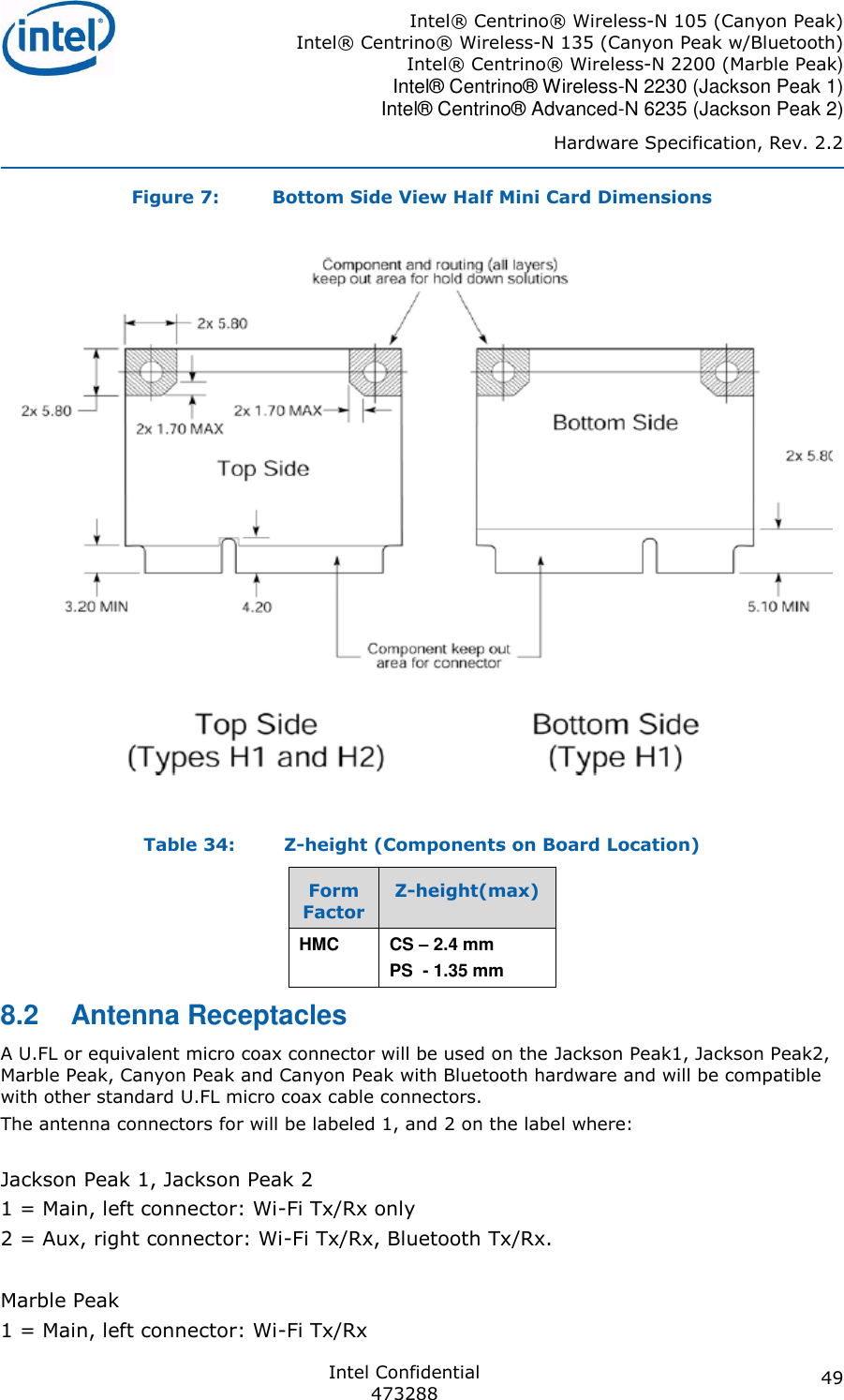
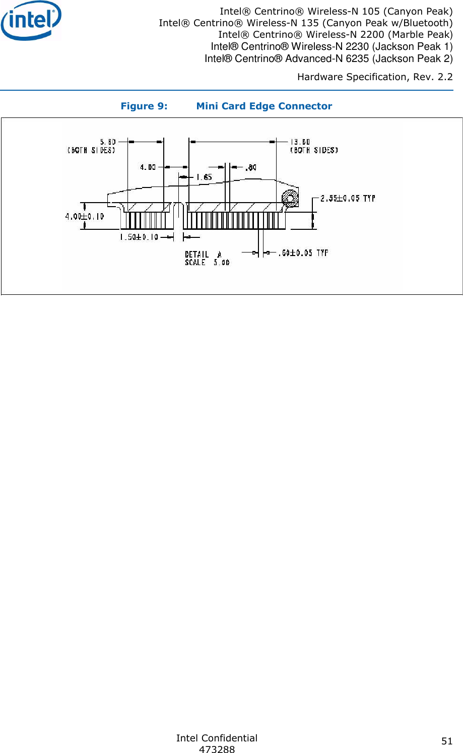
![Intel® Centrino® Wireless-N 105 (Canyon Peak) Intel® Centrino® Wireless-N 135 (Canyon Peak w/Bluetooth) Intel® Centrino® Wireless-N 2200 (Marble Peak) Intel® Centrino® Wireless-N 2230 (Jackson Peak 1) Intel® Centrino® Advanced-N 6235 (Jackson Peak 2) Hardware Specification, Rev. 2.2 Intel Confidential 473288 26 CyP, CYP w/Bluetooth hardware devices shall not support PCI Express* ASPM L0s power state , and Shall support the L1 state that has high value as a Power saving state. Not supporting L0s leads to measures that need to be taken in the Platform level to disable the L0s ability in the Root side (chip-set/ICH side) or else a system hang may occur; For these devices below steps must be taken to limit the L0s ASPM State During normal ASPM initialization: Scan each PCI Express* Root Port for the JP1, JP2, MP, Cy or CyP+Bluetooth Wireless Ethernet Controller PCI Vendor/Device IDs. For all Controllers listed above, when enabling ASPM, disable L0s for the root port (ICH Side) regardless of the support reported. Disabling L0s for the root port should be done via the Link Control Register (Offset 10h) [1:0]. These values should be restored during an S3 resume. Note: The device driver shall disable the L0s on its side (endpoint) and shall enable L1a to maintain low Power consumption capabilities. Repeat the steps for all applicable network controllers in the system. Microsoft Windows Vista* (and Microsoft Windows 7*) may Override the BIOS ASPM Settings: JP1, JP2, MP, CyP or CyP+Bluetooth (need to be replaced with official naming/Part Number) hardware devices present and native PCI Express support is enabled via _OSC method, and then the FACP Bit IAPC_BOOT_ARCH (bit 4) needs to be set. This will leave ASPM control in the hands of the platform/system BIOS. FACP bit, if set, indicates to the OSPM that it must not enable OSPM ASPM control on the platform. No issue is expected with BIOS that does not use OSC method. information regarding the IAPC_BOOT_ARCH bit. 3.4 Mini Card DC Specifications For Mini Card DC Specification refer to PCI Express Mini Card Electromechanical Specification and Input Power and Voltage Tolerance ECN. The Max Power (as max defined in the Mini Card Spec) is 2000mW =>667mA (need at least 2 Power Pins of the 5 exists in the Mini Card spec, Max limit for each Pin is 500mA). 3.5 Wireless Disable 3.5.1 Wi-Fi Hardware RF Disable The W_Disable# input signal on Pin 20 of the Mini Card system connector allows the hardware to disable the Wi-Fi RF circuitry. The W_Disable# signal is an active low signal that when driven low by the platform disables Wi-Fi radio operation. The assertion and de-assertion of the W_Disable# signal is asynchronous to any platform clock. All transients resulting from mechanical switches need to be de-bounced by platform circuitry. This signal is capable of: Minimum Sink Current to ground = 1 mA per card Note: The 1mA value is taken from the PCI Express Mini Card electrical Specification. However, the JP1, JP2, MP, CyP, CyP w/Bluetooth case should be able to drive a much lower current when the W_Disable# signal is active low (~50uA). In normal operation, the card must stop any RF activity within seconds after the W_Disable# signal is asserted. The hardware must assure that the disable operation is not dependent on](https://usermanual.wiki/Getac-Technology/6235/User-Guide-1831965-Page-26.png)
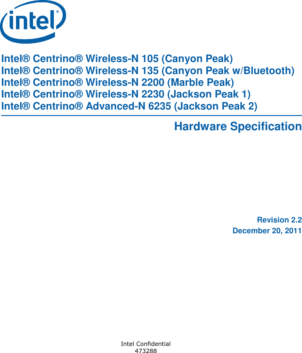
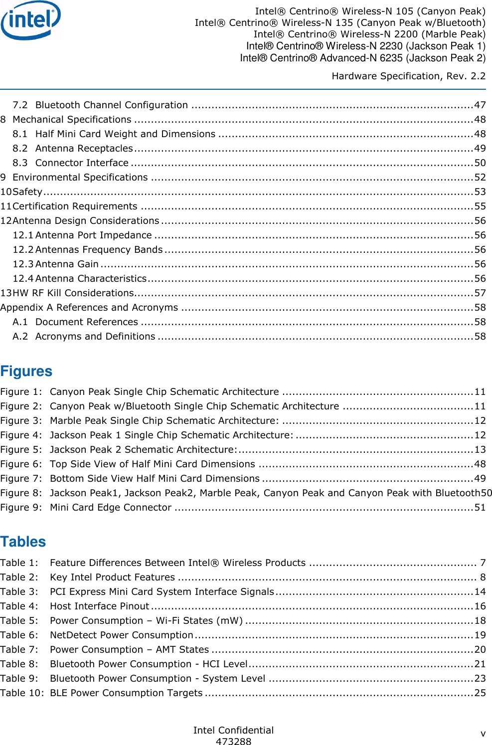
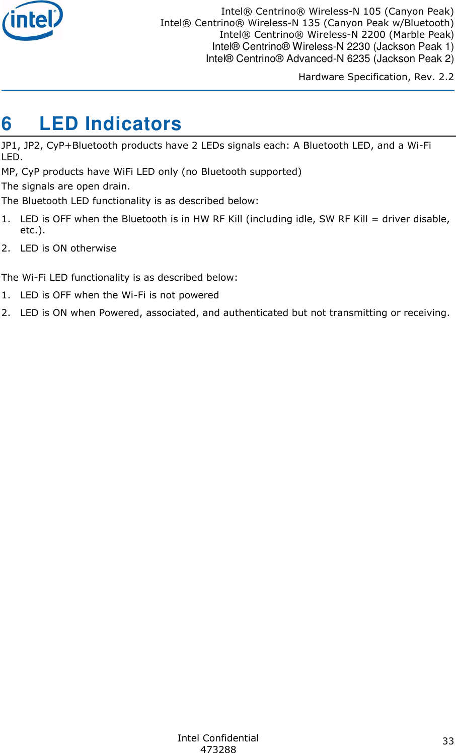
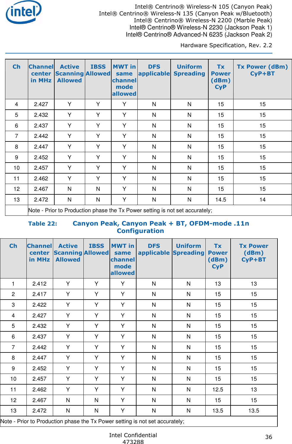
![Intel® Centrino® Wireless-N 105 (Canyon Peak) Intel® Centrino® Wireless-N 135 (Canyon Peak w/Bluetooth) Intel® Centrino® Wireless-N 2200 (Marble Peak) Intel® Centrino® Wireless-N 2230 (Jackson Peak 1) Intel® Centrino® Advanced-N 6235 (Jackson Peak 2) Hardware Specification, Rev. 2.2 Intel Confidential 473288 27 SW state. The Card should resume normal operation within seconds of de-assertion of the W_Disable# signal. Note: Due to the potential of a software disable state, the Wi-Fi radio will The system is required to assure that W_Disable# be in a deterministic state (asserted or de-asserted) whenever power is applied to the Card (i.e., whenever either +3.3V is present). For JP2 the internal pull up resistor on this pin is ~37Kohm typical value (Min 25Kohm, Max 58Kohm). For JP1, CyP, MP, CyP+Bluetooth the internal pull up resistor on this pin is ~45Kohm typical value (Min 34Kohm, Max 71Kohm). The operation of the signal is as following Float = Radio is on. Off (Active low: Vil = 0.0v [+/-0.3]) = Radio transmitter is turned off and incapable of transmitting Table 12: Hardware RF Disable Logic Software Setting Hardware Switch Radio Transmitter Function Enabled Enabled/Float Enabled Enabled Disabled/Low Disabled Disabled Enabled/Float Disabled Disabled Disabled/Low Disabled 3.5.2 Bluetooth Hardware RF Disable W_DISABLE#_2 is the HW RF Kill for the Bluetooth radio. Asserting W_DISABLE#_2 signal will result in a complete shutdown of the Bluetooth part.The result from the user perspective is like removing the Bluetooth device from the laptop. The W_DISABLE#_2 internal pull up resistor is 59Kohm typical value (Min 42Kohm, Max 88Kohm). Optional SW RF Kill: This feature can be enabled during installation using a special command. See TPS for more details As opposed to the HW RF kill which is similar to device removal, the SW RF kill is actually a Bluetooth driver disable command. The following table summarizes the differences between SW and HW RF kill options: Option Bluetooth HW RF Kill Bluetooth SW RF Kill RF Activity Off Off USB Interface Off On LED State Off On (*) Assuming WiFi is in RF Kill too. Please note, that conflicts between Bluetooth SW and HW RF kill commands might occur. The SW stack does not handle such conflicts. Therefore, a recommended practice is not to enable both mechanisms. If the OEM does wish to enable both Bluetooth SW and HW RF Kill mechanisms, it is recommended to at least to pop up a message that user needs to make sure Bluetooth activity.](https://usermanual.wiki/Getac-Technology/6235/User-Guide-1831965-Page-27.png)

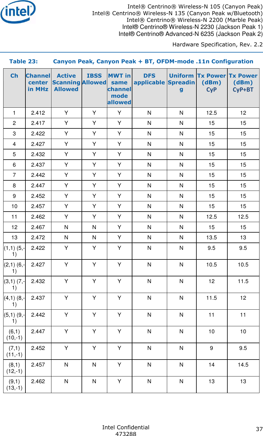

![Intel® Centrino® Wireless-N 105 (Canyon Peak) Intel® Centrino® Wireless-N 135 (Canyon Peak w/Bluetooth) Intel® Centrino® Wireless-N 2200 (Marble Peak) Intel® Centrino® Wireless-N 2230 (Jackson Peak 1) Intel® Centrino® Advanced-N 6235 (Jackson Peak 2) Hardware Specification, Rev. 2.2 Intel Confidential 473288 57 13 HW RF Kill Considerations The Wi-Fi RF Kill is supported via Pin #20 (W_Disable), and this is similar to previous products. The Bluetooth RF Kill is supported via Pin #51 (W_Disable#2) Since both RF Kill signals are active low, and there is an internal pull up this means that they can be left not connected, and both Wi-Fi and Bluetooth will be enabled. To disable the BluetoothVil = 0.0v [+/-0.3]) should be applied to the W_disable#2 pin. To disable the Wi-Vil = 0.0v [+/-0.3]) should be applied to the W_disable# pin. In order to test Intel Wireless on legacy platforms (prior to Huron River), the W_disable#2 pin If for any reason, the W_disable#2 pin tform then Bluetooth would be disabled.](https://usermanual.wiki/Getac-Technology/6235/User-Guide-1831965-Page-57.png)