Getac Technology 6235 WLAN/BT Module User Manual
Getac Technology Corporation WLAN/BT Module
User Manual

Intel Confidential
473288
Intel® Centrino® Wireless-N 105 (Canyon Peak)
Intel® Centrino® Wireless-N 135 (Canyon Peak w/Bluetooth)
Intel® Centrino® Wireless-N 2200 (Marble Peak)
Intel® Centrino® Wireless-N 2230 (Jackson Peak 1)
Intel® Centrino® Advanced-N 6235 (Jackson Peak 2)
Hardware Specification
Revision 2.2
December 20, 2011

Intel® Centrino® Wireless-N 105 (Canyon Peak)
Intel® Centrino® Wireless-N 135 (Canyon Peak w/Bluetooth)
Intel® Centrino® Wireless-N 2200 (Marble Peak)
Intel® Centrino® Wireless-N 2230 (Jackson Peak 1)
Intel® Centrino® Advanced-N 6235 (Jackson Peak 2)
Hardware Specification, Rev. 2.2
Intel Confidential
473288
ii
Legal Disclaimer
INFORMATION IN THIS DOCUMENT IS PROVIDED IN CONNECTION WITH INTEL PRODUCTS. NO LICENSE, EXPRESS
OR IMPLIED, BY ESTOPPEL OR OTHERWISE, TO ANY INTELLECTUAL PROPERTY RIGHTS IS GRANTED BY THIS
DOCUMENT. EXCEPT AS PROVIDED IN INTEL'S TERMS AND CONDITIONS OF SALE FOR SUCH PRODUCTS, INTEL
ASSUMES NO LIABILITY WHATSOEVER AND INTEL DISCLAIMS ANY EXPRESS OR IMPLIED WARRANTY, RELATING
TO SALE AND/OR USE OF INTEL PRODUCTS INCLUDING LIABILITY OR WARRANTIES RELATING TO FITNESS FOR A
PARTICULAR PURPOSE, MERCHANTABILITY, OR INFRINGEMENT OF ANY PATENT, COPYRIGHT OR OTHER
INTELLECTUAL PROPERTY RIGHT.
UNLESS OTHERWISE AGREED IN WRITING BY INTEL, THE INTEL PRODUCTS ARE NOT DESIGNED NOR INTENDED
FOR ANY APPLICATION IN WHICH THE FAILURE OF THE INTEL PRODUCT COULD CREATE A SITUATION WHERE
PERSONAL INJURY OR DEATH MAY OCCUR.
Intel may make changes to specifications and product descriptions at any time, without notice. Designers must not
rely on the absence or characteristics of any features or instructions marked "reserved" or "undefined." Intel
reserves these for future definition and shall have no responsibility whatsoever for conflicts or incompatibilities
arising from future changes to them. The information here is subject to change without notice. Do not finalize a
design with this information.
The products described in this document may contain design defects or errors known as errata which may cause
the product to deviate from published specifications. Current characterized errata are available on request.
Contact your local Intel sales office or your distributor to obtain the latest specifications and before placing your
product order.
Copies of documents which have an order number and are referenced in this document, or other Intel literature,
may be obtained by calling 1-800-548-4725, or go to: http://www.intel.com/design/literature.htm
Software and workloads used in performance tests may have been optimized for performance only on Intel microprocessors.
Performance tests, such as SYSmark and MobileMark, are measured using specific computer systems, components, software,
operations and functions. Any change to any of those factors may cause the results to vary. You should consult other information
and performance tests to assist you in fully evaluating your contemplated purchases, including the performance of that product
when combined with other products.
Canyon Peak, Marble Peak, Jackson Peak, Taylor Peak and other code names featured are used internally within
Intel to identify products that are in development and not yet publicly announced for release. Customers, licensees
and other third parties are not authorized by Intel to use code names in advertising, promotion or marketing of any
product or services and any such use of Intel's internal code names is at the sole risk of the user.
Actual measurement results may vary depending on the specific hardware and software configuration of the
computer system measured, the characteristics of those computer components not under direct measurement,
variation in processor manufacturing processes, the benchmark utilized, the specific ambient conditions under
which the measurement is taken, and other factors.
All plans, features and dates are preliminary and subject to change without notice.
* Third-party brands and names are the property of their respective owners.
Copyright © Intel Corporation 2011

Intel® Centrino® Wireless-N 105 (Canyon Peak)
Intel® Centrino® Wireless-N 135 (Canyon Peak w/Bluetooth)
Intel® Centrino® Wireless-N 2200 (Marble Peak)
Intel® Centrino® Wireless-N 2230 (Jackson Peak 1)
Intel® Centrino® Advanced-N 6235 (Jackson Peak 2)
Hardware Specification, Rev. 2.2
Intel Confidential
473288
iii
Document Revision History
Document
Number
Document
Revision
Number
Date
Comments
473288
1.0
April 7, 2011
Initial release
473288
2.0
August 18, 2011
Added:
4.2 PCI Interface
7.2 Antenna Gain for Product and Country
Certifications
Updates:
Table 2 Key Intel® Wireless Features
8.1 Half Mini Card Weight and Dimensions
473288
2.1
December 9, 2011
Updated
Table 4 Host Interface Pinout
6 LED Indicators
8.2 Antenna Receptacles
Added
3.3.3 Wi-Fi Power Consumption
3.3.4 Bluetooth Power Consumption
7.1.5 Channel Configuration Tables/RF Output
Power
473288
2.2
December 20, 2011
Updated
Table 5 Power Consumption Wi-Fi States
(mW)
Added
Table 6 NetDetect Power Consumption

Intel® Centrino® Wireless-N 105 (Canyon Peak)
Intel® Centrino® Wireless-N 135 (Canyon Peak w/Bluetooth)
Intel® Centrino® Wireless-N 2200 (Marble Peak)
Intel® Centrino® Wireless-N 2230 (Jackson Peak 1)
Intel® Centrino® Advanced-N 6235 (Jackson Peak 2)
Hardware Specification, Rev. 2.2
Intel Confidential
473288
iv
Contents
1 Introduction ........................................................................................................................ 7
1.1 Key Features ................................................................................................................ 8
2 System Architecture ............................................................................................................ 10
2.1 Frequency Stability ....................................................................................................... 10
2.2 Data Transmission ........................................................................................................ 10
3 Electrical Specifications ........................................................................................................ 14
3.1 Hardware Interface Signals ............................................................................................ 14
3.2 Pinout Definitions ......................................................................................................... 16
3.2.1 No Connect (NC) Signals ..................................................................................... 17
3.2.2 Power ............................................................................................................... 17
3.2.3 Ground (GND) .................................................................................................... 18
3.3 Module level Power Consumption .................................................................................... 18
3.3.1 Power Pins ......................................................................................................... 18
3.3.2 Power Consumption Definitions ............................................................................ 18
3.3.3 Wi-Fi Power Consumption .................................................................................... 18
3.3.4 Bluetooth Power Consumption .............................................................................. 20
3.3.5 ACPI Device State Support................................................................................... 25
3.3.6 Enabling Ethernet Controllers with ASPM ............................................................... 25
3.4 Mini Card DC Specifications ............................................................................................ 26
3.5 Wireless Disable ........................................................................................................... 26
3.5.1 Wi-Fi Hardware RF Disable ................................................................................... 26
3.5.2 Bluetooth Hardware RF Disable ............................................................................ 27
3.6 Auxiliary Signal (PERST#, WAKE#, REFCLK) .................................................................... 28
3.7 Mini Card Supply Ripple Limits ....................................................................................... 28
4 Host interface Description .................................................................................................... 29
4.1 USB Interface .............................................................................................................. 29
4.2 PCI Interface ............................................................................................................... 29
5 Thermal Specifications ......................................................................................................... 30
5.1 Thermal Dissipation ...................................................................................................... 30
5.2 Thermal Specifications .................................................................................................. 31
5.2.1 Thermal Management and Critical Shutdown .......................................................... 31
5.2.2 Wi-Fi Thermal Throttling ...................................................................................... 31
6 LED Indicators .................................................................................................................... 33
7 Regulatory Channel Support and Output Power ....................................................................... 34
7.1 Wi-Fi Channel Configuration ........................................................................................... 34
7.1.1 Channel Configuration Tables ............................................................................... 34
7.1.2 Antenna Gain for Product and Country Certifications ............................................... 34
7.1.3 Maximum Legacy and MIMO RF Output Power ........................................................ 34
7.1.4 Maximum Bluetooth Output Power ........................................................................ 35
7.1.5 ................................................................. 35
7.1.6 Channel Configuration Tables / RF Output Power .................................................... 35

Intel® Centrino® Wireless-N 105 (Canyon Peak)
Intel® Centrino® Wireless-N 135 (Canyon Peak w/Bluetooth)
Intel® Centrino® Wireless-N 2200 (Marble Peak)
Intel® Centrino® Wireless-N 2230 (Jackson Peak 1)
Intel® Centrino® Advanced-N 6235 (Jackson Peak 2)
Hardware Specification, Rev. 2.2
Intel Confidential
473288
v
7.2 Bluetooth Channel Configuration .................................................................................... 47
8 Mechanical Specifications ..................................................................................................... 48
8.1 Half Mini Card Weight and Dimensions ............................................................................ 48
8.2 Antenna Receptacles ..................................................................................................... 49
8.3 Connector Interface ...................................................................................................... 50
9 Environmental Specifications ................................................................................................ 52
10 Safety ................................................................................................................................ 53
11 Certification Requirements ................................................................................................... 55
12 Antenna Design Considerations ............................................................................................. 56
12.1 Antenna Port Impedance ............................................................................................... 56
12.2 Antennas Frequency Bands ............................................................................................ 56
12.3 Antenna Gain ............................................................................................................... 56
12.4 Antenna Characteristics ................................................................................................. 56
13 HW RF Kill Considerations..................................................................................................... 57
Appendix A References and Acronyms ....................................................................................... 58
A.1 Document References ................................................................................................... 58
A.2 Acronyms and Definitions .............................................................................................. 58
Figures
Figure 1: Canyon Peak Single Chip Schematic Architecture ......................................................... 11
Figure 2: Canyon Peak w/Bluetooth Single Chip Schematic Architecture ....................................... 11
Figure 3: Marble Peak Single Chip Schematic Architecture: ......................................................... 12
Figure 4: Jackson Peak 1 Single Chip Schematic Architecture: ..................................................... 12
Figure 5: Jackson Peak 2 Schematic Architecture: ...................................................................... 13
Figure 6: Top Side View of Half Mini Card Dimensions ................................................................ 48
Figure 7: Bottom Side View Half Mini Card Dimensions ............................................................... 49
Figure 8: Jackson Peak1, Jackson Peak2, Marble Peak, Canyon Peak and Canyon Peak with Bluetooth50
Figure 9: Mini Card Edge Connector ......................................................................................... 51
Tables
Table 1: Feature Differences Between Intel® Wireless Products .................................................. 7
Table 2: Key Intel Product Features ......................................................................................... 8
Table 3: PCI Express Mini Card System Interface Signals ........................................................... 14
Table 4: Host Interface Pinout ................................................................................................ 16
Table 5: Power Consumption Wi-Fi States (mW) .................................................................... 18
Table 6: NetDetect Power Consumption ................................................................................... 19
Table 7: Power Consumption AMT States .............................................................................. 20
Table 8: Bluetooth Power Consumption - HCI Level ................................................................... 21
Table 9: Bluetooth Power Consumption - System Level ............................................................. 23
Table 10: BLE Power Consumption Targets ................................................................................ 25

Intel® Centrino® Wireless-N 105 (Canyon Peak)
Intel® Centrino® Wireless-N 135 (Canyon Peak w/Bluetooth)
Intel® Centrino® Wireless-N 2200 (Marble Peak)
Intel® Centrino® Wireless-N 2230 (Jackson Peak 1)
Intel® Centrino® Advanced-N 6235 (Jackson Peak 2)
Hardware Specification, Rev. 2.2
Intel Confidential
473288
vi
Table 11: Supported D-States .................................................................................................. 25
Table 12: Hardware RF Disable Logic ........................................................................................ 27
Table 13: USB Interface Signal Description ................................................................................ 29
Table 14: Jackson Peak1 Thermal Dissipation............................................................................. 30
Table 15: Jackson Peak2 Thermal Dissipation............................................................................. 30
Table 16: Canyon Peak Thermal Dissipation ............................................................................... 30
Table 17: Canyon Peak with Bluetooth Thermal Dissipation.......................................................... 30
Table 18: Marble Peak Thermal Dissipation ................................................................................ 30
Table 19: JacksonPeak1, JacksonPeak2, Marble Peak, Canyon Peak and Canyon Peak with Bluetooth
Thermal Management ........................................................................................................ 31
Table 20: JacksonPeak1, JacksonPeak2, Marble Peak, Canyon Peak and Canyon eak with Bluetooth
Scan Details ..................................................................................................................... 34
Table 21: Canyon Peak, Canyon Peak + BT, CCK-Mode Configuration ........................................... 35
Table 22: Canyon Peak, Canyon Peak + BT, OFDM-mode .11n Configuration ................................. 36
Table 23: Canyon Peak, Canyon Peak + BT, OFDM-mode .11n Configuration ................................. 37
Table 24: Jackson Peak2, CCK-Mode Configuration ..................................................................... 38
Table 25: Jackson Peak2, OFDM-mode non-.11n Configuration .................................................... 38
Table 26: Jackson Peak 2, OFDM-mode .11n Configuration .......................................................... 40
Table 27: Jackson Peak1, CCK-Mode Configuration ..................................................................... 42
Table 28: Jackson Peak1 OFDM-mode non-.11n Configuration ..................................................... 43
Table 29: Jackson Peak1 OFDM-mode .11n Configuration ............................................................ 43
Table 30: Marble Peak CCK-Mode Configuration ......................................................................... 44
Table 31: Marble Peak OFDM-mode non-.11n Configuration ......................................................... 45
Table 32: Marble Peak OFDM-mode .11n Configuration ............................................................... 45
Table 33: Intel® Centrino® Wireless Product Weights ................................................................ 48
Table 34: Z-height (Components on Board Location) .................................................................. 49
Table 35: Operational Conditions .............................................................................................. 52
Table 36: Storage conditions ................................................................................................... 52
Table 37: Wi-Fi Safety and Regulatory USA ............................................................................... 53
Table 38: Wi-Fi Safety and Regulatory Europe ........................................................................... 53
Table 39: Wi-Fi Safety and Regulatory Japan ............................................................................. 53
Table 40: Wi-Fi Safety and Regulatory Australia / New Zealand .................................................... 53
Table 41: Wi-Fi Safety and Regulatory Other Geographies ........................................................... 54
Table 42: Jackson Peak1, Jackson Peak2, Marble Peak, Canyon Peak and Canyon Peak with Bluetooth
Certification Requirements ................................................................................................. 55

Intel® Centrino® Wireless-N 105 (Canyon Peak)
Intel® Centrino® Wireless-N 135 (Canyon Peak w/Bluetooth)
Intel® Centrino® Wireless-N 2200 (Marble Peak)
Intel® Centrino® Wireless-N 2230 (Jackson Peak 1)
Intel® Centrino® Advanced-N 6235 (Jackson Peak 2)
Hardware Specification, Rev. 2.2
Intel Confidential
473288
7
1 Introduction
The Intel® Centrino® Wireless Products include the following products:
Intel® Centrino® Wireless-N 105 code name Canyon Peak (CyP) is a discrete 1x1
Wi-th generation 802.11n Wi-Fi
solution and supports 2.4GHz band. It operates on a 40MHz wide channel, reaching
PHY rates of up to 150Mbps.
Intel® Centrino® Wireless-N 135 code name Canyon Peak w/Bluetooth (CyP w/BT)
is the Wireless LAN (Wi-Fi) and Bluetooth (BT) combination product that supports
WiFi 1x1 802.11n in the 2.4GHz band. It operates on a 40MHz wide channel, reaching
PHY rates of up to 150Mbps. Canyon Peak w/Bluetooth uses CSR Bluetooth 8th
generation core that supports Bluetooth 3.0 standard, and Bluetooth low energy
technology (BLE). In addition, Canyon Peak w/Bluetooth supports the Bluetooth 4.0
standard (which includes BLE and Bluetooth 3.0+HS)
Intel® Centrino® Wireless-N 2200 code name Marble Peak (MP) is a discrete 2x2
Wi-Fi single chip solution. Marble th generation 802.11n WiFi
solution and supports the 2.4GHz band. It operates on a 40MHz wide channel,
reaching PHY rates of up to 300Mbps.
Intel® Centrino® Wireless-N 2230 code name Jackson Peak1 (JP1) is the Wireless
LAN (Wi-Fi) and Bluetooth (BT) combination single chip supporting the 2.4GHz band.
It operates on a 40MHz wide channel, reaching PHY rates of up to 300Mbps. In
addition, Jackson Peak1 supports Bluetooth 4.0 standard (which includes BLE and
Bluetooth 3.0+HS).
Intel® Centrino® Advanced-N 6235 code name Jackson Peak2 (JP2) is a Wireless
LAN (WiFi) and Bluetooth (BT) combination dual chip solution supporting both 2.4GHz
and 5GHz bands. It operates on a 40MHz wide channel, reaching PHY rates of up to
300Mbps. Jackson Peak2 supports Bluetooth 4.0 standard (which includes BLE and
Bluetooth 3.0+HS).
Table 1 summarizes the differences between the different products.
Table 1: Feature Differences Between Intel® Wireless Products
Feature
Jackson Peak 1
Jackson Peak 2
Canyon Peak /
Canyon Peak
w/Bluetooth
Marble Peak
Wi-Fi
standard
2x2 bgn
2x2 agn
1x1 bgn
2x2 bgn
Antennas
2
2
2
2
Wi-Fi TX
chains
2 chain
2 chains
1 Chain
2 chains
Wi-Fi RX
Chains
2 chains
2 Chains
1 chain
2 Chains
Antenna
Diversity
N/A
N/A
Enabled when Bluetooth
is inactive
N/A

Intel® Centrino® Wireless-N 105 (Canyon Peak)
Intel® Centrino® Wireless-N 135 (Canyon Peak w/Bluetooth)
Intel® Centrino® Wireless-N 2200 (Marble Peak)
Intel® Centrino® Wireless-N 2230 (Jackson Peak 1)
Intel® Centrino® Advanced-N 6235 (Jackson Peak 2)
Hardware Specification, Rev. 2.2
Intel Confidential
473288
8
Feature
Jackson Peak 1
Jackson Peak 2
Canyon Peak /
Canyon Peak
w/Bluetooth
Marble Peak
Antenna
Allocation
a. Wi-Fi Only
b. Shared Wi-Fi
w/Bluetooth
a. Wi-Fi Only
b. Shared Wi-Fi
w/Bluetooth
a. Wi-Fi Only
b. Bluetooth (When
Bluetooth is inactive, used
as Wi-Fi RX diversity
antenna)
a. Wi-Fi Only
b. Wi-Fi Only
Wi-Fi Rx
Throughput
300Mbps
300Mbps
150Mbps
300Mbps
Wi-Fi Tx
Throughput
300Mbps
300Mbps
150Mbps
300Mbps
Bluetooth
Core
Bluetooth 4.0
Bluetooth 4.0
Bluetooth 4.0 (for CyP/BT)
N/A
Intel® WiDi
Support
Yes
Yes
No
Yes
Intel® AMT
Support
No
AMT8.0
No
No
Single/Dual
chip
Single
Dual
Single
Single
*Canyon Peak has antenna diversity
**For Bluetooth, a separate antenna is allocated
1.1 Key Features
Key features of Intel products are listed in Table 2.
Note: Not all products support all the features listed in Table 2.
Table 2: Key Intel Product Features
Feature
Description
Operating System Support
Microsoft Windows 7, Microsoft Windows 8, Linux
Microsoft Windows XP and Microsoft Windows Vista shall be
supported on legacy (AGN) products
Platform Compatibility
Netbook: Cedar Trail, SW support for Pine Trail
Notebook: Chief River, SW support for Huron River, Sugar
Bay, Calpella, and Montevina)
Wi-Fi Alliance Certifications
802.11n, 802.11w, WPA, WPS, WMM, WFD, Wi-Fi Direct
Microsoft Certifications
Microsoft Windows 8 Logo, Microsoft Windows 7 Logo.
Legacy: Premium Logo (Microsoft Windows Vista), Designed
for Microsoft Windows XP

Intel® Centrino® Wireless-N 105 (Canyon Peak)
Intel® Centrino® Wireless-N 135 (Canyon Peak w/Bluetooth)
Intel® Centrino® Wireless-N 2200 (Marble Peak)
Intel® Centrino® Wireless-N 2230 (Jackson Peak 1)
Intel® Centrino® Advanced-N 6235 (Jackson Peak 2)
Hardware Specification, Rev. 2.2
Intel Confidential
473288
9
Feature
Description
Bluetooth
Integrated Bluetooth
CSR Bluetooth on JP1, JP2 and CyP + Bluetooth
Bluetooth Certification
BT3.0 HS - AMP Subsystem End Product
BT4.0 LE – Smart Ready
Intel® Smart Connect Technology
Instant connectivity <1sec;
Always Updated with NetDetect
Wake On WLAN (and later SCT Always Reachable)
Intel® Wireless Display
Wi-Di Professional- Phase 1 – Laptop as GO, supporting user
eviction and Roam to non-DFS channel when activated
(limited to same channel)
Software Compatibility
Intel® PRO/Set Wireless Software v15.0
Intel® Active Management Technology
v8.0
Support for Intel® AMT 8.0 on Chief River Platforms with
Cougar Point
Cisco Compatible Extensions (CCX)
Support for CCX1-4 on XP, Vista, Win7, and Win8
Advanced Bluetooth-Wi-Fi Co-Existence
3-wire based, UART Messaging, auto tight/loose Coexistence
scheme
Platform Power / Extending battery life
Adaptive Snoozing, Smart FIFO, beacon filtering, reduced
interrupts per packet (also part of Windows 8 logo
requirements)
Security
uCode SRAM Program memory lock

Intel® Centrino® Wireless-N 105 (Canyon Peak)
Intel® Centrino® Wireless-N 135 (Canyon Peak w/Bluetooth)
Intel® Centrino® Wireless-N 2200 (Marble Peak)
Intel® Centrino® Wireless-N 2230 (Jackson Peak 1)
Intel® Centrino® Advanced-N 6235 (Jackson Peak 2)
Hardware Specification, Rev. 2.2
Intel Confidential
473288
10
2 System Architecture
Jackson Peak1 and Canyon Peak with Bluetooth contain a single chip for Wi-Fi+Bluetooth,
including Wi-Fi MAC and PHY as well as Bluetooth MAC and PHY. Jackson Peak 2 is a 2 chip
solution. All the modules are HMC (Half Mini Card) format. Marble Peak and Canyon Peak are
both WiFi only solutions.
2.1 Frequency Stability
The 40MHz clock has 20ppm maximum frequency stability. It is multiplied up to generate the
transmit signal. Hence when operating in the b/g band at 2.412GHz we will have an error of
2.412GHz*20ppm when tuned to the lower channel and at the extreme it will be 2.484GHz *
20ppm when tuned to the upper channel. When operating in the band, it has a frequency error
of the operation frequency *20ppm.
2.2 Data Transmission
Data transmission is always initiated by software, which is then passed down through the
MAC, through the digital and analog baseband, and finally to the RF chip. Several special
packets (ACKs, CTS, PS Poll, etc.) are initiated by the MAC. These are the only ways the digital
baseband portion will turn on the RF transmitter, which it then turns off at the end of the
packet. Therefore, the transmitter
is being transmitted.
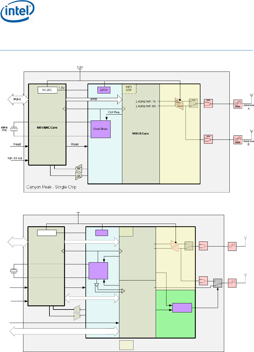
The below schemes are used to depict the solution, and are not necessarily the architecture
requirements and design.
Intel® Centrino® Wireless-N 105 (Canyon Peak)
Intel® Centrino® Wireless-N 135 (Canyon Peak w/Bluetooth)
Intel® Centrino® Wireless-N 2200 (Marble Peak)
Intel® Centrino® Wireless-N 2230 (Jackson Peak 1)
Intel® Centrino® Advanced-N 6235 (Jackson Peak 2)
Hardware Specification, Rev. 2.2
Intel Confidential
473288
11
Figure 1: Canyon Peak Single Chip Schematic Architecture
Figure 2: Canyon Peak w/Bluetooth Single Chip Schematic Architecture
WiFi-R Core
BT Core
40MHz
XTAL
Balun
BT RX/TX
Clock Block
CLK Req.
CLK Req.
RF Control
Block
2G LNA
SPDT
WiFi
2G iPA
Balun
WiFi MAC Core
DC2DC LDOs
1.3V
Reset Reset
WiFi
OTP
WiFi RF Kill
SPDT
Diplexer Antenna
B
Diplexer Antenna
A
USB2 (FS)
CCI
MRB
BT RF Kill
Canyon Peak BT - Single Chip
2.4GHz WiFi RX
2.4GHz WiFi TX
3.3V
BT OTP
PCI-E
ADC
DAC
Intel® Centrino® Wireless-N 105 (Canyon Peak)
Intel® Centrino® Wireless-N 135 (Canyon Peak w/Bluetooth)
Intel® Centrino® Wireless-N 2200 (Marble Peak)
Intel® Centrino® Wireless-N 2230 (Jackson Peak 1)
Intel® Centrino® Advanced-N 6235 (Jackson Peak 2)
Hardware Specification, Rev. 2.2
Intel Confidential
473288
12
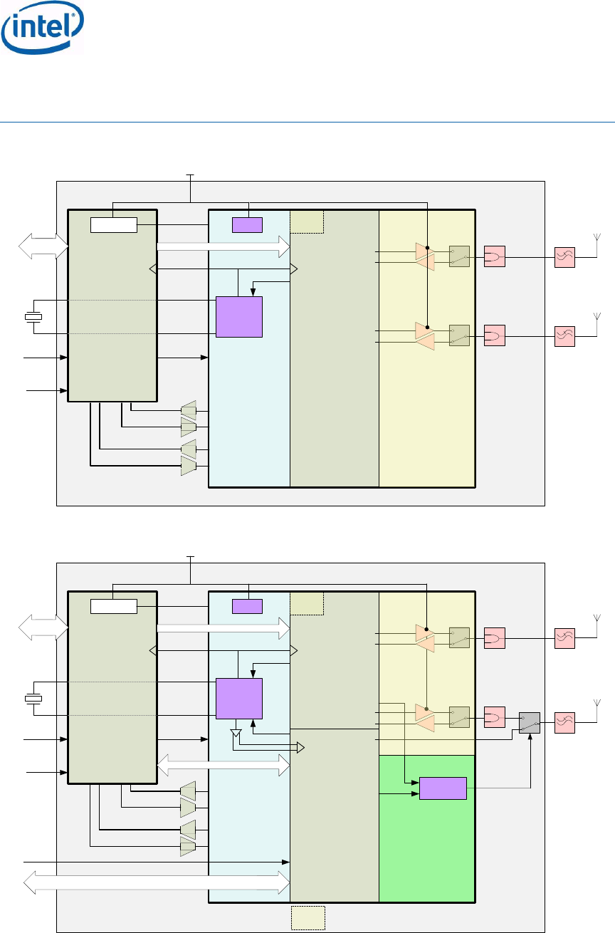
Figure 3: Marble Peak Single Chip Schematic Architecture:
Figure 4: Jackson Peak 1 Single Chip Schematic Architecture:
WiFi-R Core
40MHz
XTAL
WiFi
2G iPA
Balun
Clock Block
CLK Req.
2G LNA
SPDT
WiFi
2G iPA
Balun
WiFi MAC Core
DC2DC LDOs
1.3V
Reset Reset
WiFi
OTP
WiFi RF Kill
WiFi
2G LNA
SPDT
Diplexer Antenna
B
Diplexer Antenna
A
MRB
Marble Peak 1 - Single Chip
3.3V
2.4GHz WiFi RX
2.4GHz WiFi TX
2.4GHz WiFi RX
2.4GHz WiFi TX
PCI-E
ADC
DAC
ADC
DAC
WiFi-R Core
BT Core
40MHz
XTAL
2.4GHz WiFi RX
WiFi
2G iPA
Balun
2.4GHz WiFi TX
BT RX/TX
Clock Block
CLK Req.
CLK Req.
RF Control
Block
2.4GHz WiFi RX
SPDT
WiFi
2G iPA
2G LNA
Balun
2.4GHz WiFi TX
WiFi MAC Core
DC2DC LDOs
1.3V
Reset Reset
WiFi
OTP
WiFi RF Kill
WiFi
2G LNA
SPDT
SPDT
Diplexer Antenna
B
Diplexer Antenna
A
USB2 (FS)
CCI
MRB
BT RF Kill
Jackson Peak 1 - Single Chip
3.3V
BT OTP
PCI-E
ADC
DAC
ADC
DAC
Intel® Centrino® Wireless-N 105 (Canyon Peak)
Intel® Centrino® Wireless-N 135 (Canyon Peak w/Bluetooth)
Intel® Centrino® Wireless-N 2200 (Marble Peak)
Intel® Centrino® Wireless-N 2230 (Jackson Peak 1)
Intel® Centrino® Advanced-N 6235 (Jackson Peak 2)
Hardware Specification, Rev. 2.2
Intel Confidential
473288
13
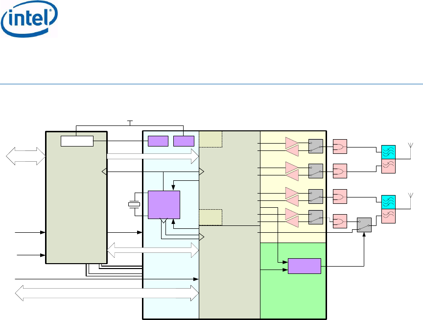
Figure 5: Jackson Peak 2 Schematic Architecture:
40MHz
XTAL
JP2 Analog-RF Chip
WiFi-R Core
BT OTP
BT Core
5GHz WiFi RX 5G LNA
WiFi
5G iPA
5GHz WiFi TX
2GHz WiFi RX
WiFi
2G iPA Balun
2GHz WiFi TX
BT RX/TX
Clock Block
CLK Req.
CLK Req.
RF Control
Block
5GHz WiFi RX 5G LNA
WiFi
5G iPA
5GHz WiFi TX
2GHz WiFi RX 2G LNA
SPDT
WiFi
2G iPA
Balun
2GHz WiFi TX
JP2 WiFi
MAC Chip
LDOs LDOs LDOs
3.3V
1.8V
Reset Reset
WiFi
OTP
WiFi RF Kill
WiFi
2G LNA
SPDT
SPDT Diplexer
Antenna
B
Diplexer
Antenna
A
SPDT Balun
SPDT Balun
USB2 (FS)
CCI
MRB
BT RF Kill
Dual Chip
PCI-E
Clink

Intel® Centrino® Wireless-N 105 (Canyon Peak)
Intel® Centrino® Wireless-N 135 (Canyon Peak w/Bluetooth)
Intel® Centrino® Wireless-N 2200 (Marble Peak)
Intel® Centrino® Wireless-N 2230 (Jackson Peak 1)
Intel® Centrino® Advanced-N 6235 (Jackson Peak 2)
Hardware Specification, Rev. 2.2
Intel Confidential
473288
14
3 Electrical Specifications
This section provides information about the electrical specifications for the products hardware.
The specification covers the module Hardware Interface Signals, Power Consumption, and
DC/AC characteristics. For more details please refer to the PCI Express Mini Card
Electromechanical Specification, Revision 1.2 and the PCI Express Base Specification, Revision
1.2. Mostly this is common to all 5 products. Whenever there is any change specific to one of
the products, it will be highlighted in the comments column
3.1 Hardware Interface Signals
The Hardware design is based on PCI Express Mini Card Electromechanical Specification.
System interface signals are described in the table below.
The Wi-Fi core implements PCI express, compliance to PCIe v1.2 specifications. Bluetooth uses
USB 2.0 Full Speed. The Wi-Fi core connects to the PCH through dedicated Clink interface for
OOB.
Table 3: PCI Express Mini Card System Interface Signals
Signal
Group
Signal
Direction
Description
Comments
Auxiliary
Signals
(3.3V
Compliant)
PERST#
Input
Functional Reset to
the card.
CLKREQ#
Output
Reference clock
request signal.
WAKE#
Output
Open Drain active low
signal. This signal is
used to request that
the system return
from a
sleep/suspended
state to service a
function initiated wake
event.
PCI
Express
REFCLK+,
REFCLK-
Input
PCI Express
differential reference
clock (100 MHz).
PETp0, PETn0
PERp0, PERn0
Input/Output
PCI Express x1 data
interface: One
differential transmit
pair and one
differential receive
pair.
USB
USB_D+
Input/Output
Comply with USB 2.0
specifications.
USB_D-
Input/Output
SBD
USB Side
Band Deferring
Output
Active Low, indicating
device has data to
send to host.

Intel® Centrino® Wireless-N 105 (Canyon Peak)
Intel® Centrino® Wireless-N 135 (Canyon Peak w/Bluetooth)
Intel® Centrino® Wireless-N 2200 (Marble Peak)
Intel® Centrino® Wireless-N 2230 (Jackson Peak 1)
Intel® Centrino® Advanced-N 6235 (Jackson Peak 2)
Hardware Specification, Rev. 2.2
Intel Confidential
473288
15
Signal
Group
Signal
Direction
Description
Comments
Power
+3.3Vaux
+3.3 V (4 pins)
Input
3.3 V source (Pin#24
not connected on the
card). Total power
3.3V Pins (4).
+1.5 V (3 pins)
Not
Connected
Not used
GND (14 pins)
N/A
Return current path.
LED
LED_WLAN#
Output
WLAN status
indicator.
LED_WPAN#
Output
Bluetooth status
indicator.
C-Link
Clink_RST
Input
Intel® Active
Management
Technology (Intel®
AMT) usage -
Manageability
communication
across the platform
occurs over C-link
(Controller Link).
Clink_DAT
Input/Output
C-Link_CLK
Input/Output
Wireless
Disable
W_Disable#
Input
Disables Wi-Fi RF
portion.
W_Disable_2#
Input
Disables Bluetooth
RF portion.
GND
9, 15, 21, 27,
29, 35, 37, 43
4, 18, 26, 34,
40, 50`
Ground pins.
NC
3, 5, 6, 17,
8,10,12,14,16,
24,28, 30,32,
,42, 48, (15
pins)
All NC pins are
unused. These pins
include signals that
are defined as
optional by the PCI
Express Mini Card
Electromechanical
Specification as well
as reserved pins that
are currently not in
use.

Intel® Centrino® Wireless-N 105 (Canyon Peak)
Intel® Centrino® Wireless-N 135 (Canyon Peak w/Bluetooth)
Intel® Centrino® Wireless-N 2200 (Marble Peak)
Intel® Centrino® Wireless-N 2230 (Jackson Peak 1)
Intel® Centrino® Advanced-N 6235 (Jackson Peak 2)
Hardware Specification, Rev. 2.2
Intel Confidential
473288
16
3.2 Pinout Definitions
Table 4: Host Interface Pinout
Pin #
Name
Buffer
/State
(Power-Up
Reset)
Pin #
Name
Buffer/State
(Power-Up
Reset)
1
WAKE#
Open
Drain/Tri-
State
2
+3.3Vaux
3
NC
4
GND
5
NC
6
NC
7
CLKREQ#
Open Drain
8
NC
9
GND
10
NC
11
REFCLK-
12
NC
13
REFCLK+
14
NC
15
GND
16
NC
17
NC
18
GND
19
NC. See note
below
20
W_DISABLE#
For JP2 the
internal pull up
resistor on this pin
is ~37Kohm
typical value (Min
25Kohm, Max
58Kohm).
For JP1, CyP, MP,
CyP+Bluetooth the
internal pull up
resistor on this pin
is ~45Kohm
typical value (Min
34Kohm, Max
71Kohm).
21
GND
22
PERST#
Open Drain/Tri-State
23
PETn0
24
NC
25
PETp0
26
GND
27
GND
28
NC
29
GND
30
NC
31
PERn0
32
NC
33
PERp0
34
GND
35
GND
36
USB D -

Intel® Centrino® Wireless-N 105 (Canyon Peak)
Intel® Centrino® Wireless-N 135 (Canyon Peak w/Bluetooth)
Intel® Centrino® Wireless-N 2200 (Marble Peak)
Intel® Centrino® Wireless-N 2230 (Jackson Peak 1)
Intel® Centrino® Advanced-N 6235 (Jackson Peak 2)
Hardware Specification, Rev. 2.2
Intel Confidential
473288
17
Pin #
Name
Buffer
/State
(Power-Up
Reset)
Pin #
Name
Buffer/State
(Power-Up
Reset)
37
GND
38
USB D +
39
+3.3Vaux
40
GND
41
+3.3Vaux
42
NC
43
GND
44
LED_WLAN#
Open Drain
45
C-Link_CLK
-Internal Pull
– Down ~100
kΏ
- Clink pins
should not be
used in non –
Intel®AMT
platforms
46
LED_WPAN#
Open drain
47
C-Link_DAT
48
NC
49
C-Link_RST#
-CL_RST is
active low
- CL_RST is
'low' when
AMT is
disabled
50
GND
51
W_DISABLE#_
2.
Internal Pull –
Up ~59K
typical
(Minimum:
42K.
Maximum:
88K)
52
+3.3Vaux
Note: Pins 37, 43 will be driven to GND state (This complies with Mini Card Specification
rev 1.1 Input Power ECN).
Note: The led pins (Pin#44 LED_WLAN# and Pin #46 LED_WPAN) configure to true open
drain output (disconnect the Internal Pull Down resistor) after the device is powered.
Open Drain output means that these pins output -state (Hi-Z).
Note: Pin #24 is disconnected on board, as in previous product generations.
3.2.1 No Connect (NC) Signals
Express Mini Card Electromechanical Specification as well as reserved pins that are currently
not in use.
3.2.2 Power
All power pins are connected to a power bus that should be tied to 3.3V Vaux via the
connector.

Intel® Centrino® Wireless-N 105 (Canyon Peak)
Intel® Centrino® Wireless-N 135 (Canyon Peak w/Bluetooth)
Intel® Centrino® Wireless-N 2200 (Marble Peak)
Intel® Centrino® Wireless-N 2230 (Jackson Peak 1)
Intel® Centrino® Advanced-N 6235 (Jackson Peak 2)
Hardware Specification, Rev. 2.2
Intel Confidential
473288
18
3.2.3 Ground (GND)
All ground pins are connected to a common ground bus that should be tied to system ground
via the connector.
3.3 Module level Power Consumption
3.3.1 Power Pins
Power consumption is measured on the following pins:
3.3V AUX: Pins 2, 24 (NC on card), 39, 41, and 52 are the same rail called Vaux.
Generation of PME, reporting status and enabling PME: The Mini Card uses a PME to request a
change from a power savings state (S3/S4) to the fully operational state (full power) ->
Wake-up Event (WoME).
Note: It is not allowed to connect active signals to the Mini Card input pins unless there
is a power supply provided to the power rails pins.
3.3.2 Power Consumption Definitions
Module power consumption: 3.3v rail power consumption.
Note: Power consumption numbers define the total consumed power, including 3.3v and
1.5v power rails (the 1.5v power rail is not in use).
Normal: unless stated otherwise, power consumption refers the highest averaged
power consumption value over any 1-second period.
Peak: The highest averaged value over any 10-millisecond period according to PCI
Express Mini Card Electromechanical Specification1.2.
3.3.3 Wi-Fi Power Consumption
Scale: MilliWatt (mW)
Meter: measured using Current Probe loop on the Power rails of the Mini-card (or Half Mini-
card interface/Pins)
The following tables provide product power consumption at 802.11 states. Power consumption
refers to the total consumed power, over 3.3v and 1.5v power rails (Note that the 1.5v Power
rail is not in use). Power consumption targets refer to all channels in all frequency bands for
both Netbook and Notebook supported platforms
Accuracy of power consumption values is as follows:
Values for the low power states are Mean values ±4mW.
Values for Tx and Rx power consumption are mean values ±5%.
Assumptions:
PCI-e ASPM (L1) is enabled.(Note that L0s is not used )
Transmit output power, is assumed to be 15dBm
Platform is running on Battery and Power Index is set to Max Power save (battery Life)
Table 5: Power Consumption – Wi-Fi States (mW)
Name
Description
Power Consumption Requirements (mW)
CyP
CyP+BT
JP1
JP2
MP
LB
LB
LB
LB
HB
LB
MM05/07
Mobile Mark
2005/2007 (Power
70
85
43
105
105
35

Intel® Centrino® Wireless-N 105 (Canyon Peak)
Intel® Centrino® Wireless-N 135 (Canyon Peak w/Bluetooth)
Intel® Centrino® Wireless-N 2200 (Marble Peak)
Intel® Centrino® Wireless-N 2230 (Jackson Peak 1)
Intel® Centrino® Advanced-N 6235 (Jackson Peak 2)
Hardware Specification, Rev. 2.2
Intel Confidential
473288
19
Name
Description
Power Consumption Requirements (mW)
CyP
CyP+BT
JP1
JP2
MP
LB
LB
LB
LB
HB
LB
Index =3;balanced)
Idle associated
Idle associated (1
scan) (PI=3)
65
80
43
100
100
35
Idle Unassociated
Idle unassociated (1
Scan)
22
24
24
85
85
22
Disabled/RF-
Kill/uninitialized
Disable/RF-
Kill/uninitialized
16
18
18
55
55
16
WoWLAN
Platform at S3. with
WoWLAN
Associated (1 Scan)
45
80
80
80
80
45
Average Tx legacy/1SS
Average TCP/IP
legacy or 1 SS
Transmit during
60sec, no rate
limitation
1100
1100
1050
1075
1215
1050
Average Rx Legacy/1SS
Average TCP/IP
Legacy or 1SS
Receive during
60sec, no rate
limitation.
700
700
700
715
775
700
Average Tx 2SS
Average TCP/IP 2
SS Transmit during
60sec, no rate
limitation
NA
NA
1850
1825
1835
1850
Average Rx 2SS
Average TCP/IP 2
SS Receive during
60sec, no rate
limitation.
NA
NA
1050
1065
1155
1050
Max WiFi TDP
Average power
consumption during
60 sec transmission
at max TCP/IP
throughput.
1100
1150
1920
NA
1920
1900
Table 6: NetDetect Power Consumption
Scan
Period
Marble
Peak
(mW)
LB
Jackson
Peak 1
(mW)
LB
Jackson
Peak 2
(mW)
LB+HB
Jackson
Peak 2
(mW)
LB
30s
47.56
55.24
114.26
64.72
60s
33.78
41.12
75.63
50.86

Intel® Centrino® Wireless-N 105 (Canyon Peak)
Intel® Centrino® Wireless-N 135 (Canyon Peak w/Bluetooth)
Intel® Centrino® Wireless-N 2200 (Marble Peak)
Intel® Centrino® Wireless-N 2230 (Jackson Peak 1)
Intel® Centrino® Advanced-N 6235 (Jackson Peak 2)
Hardware Specification, Rev. 2.2
Intel Confidential
473288
20
Scan
Period
Marble
Peak
(mW)
LB
Jackson
Peak 1
(mW)
LB
Jackson
Peak 2
(mW)
LB+HB
Jackson
Peak 2
(mW)
LB
180s
24.59
31.71
49.88
41.62
300s
22.76
29.82
44.73
39.77
600s
21.38
28.41
40.86
38.39
1200s
20.69
27.71
38.93
37.69
Table 7: Power Consumption – AMT States
Power Consumption
Name
Description
JP2
AMT8.0 Power Consumption S0-
Hx / M0, Mla, Rx
AMT is taking ownership of the NIC in Hx,
while actively receiving Legacy (802.11g)
mode. Traffic Scenario of TCP/IP, 1 Rx
chain, No aggregation
920
AMT8.0 Power Consumption S0-
Hx / M0, Mla, Tx
AMT is taking ownership of the NIC in Hx,
while actively transmitting in Legacy
(802.11g) mode. Traffic Scenario of TCP/IP,
1 Tx chain, No aggregation
960
AMT8.0 Power Consumption S0-
Hx / M0, MLs, Host driver
enabled
AMT is taking ownership of the NIC in Hx,
while idle between Tx and Rx and Host
Driver is enabled. Test conditions: PC at
room temperature, Two minutes average,
Max Power Save Mode, One Scan.
135
AMT8.0 Power Consumption S0-
Hx / M0, MLs, Host driver
disabled
AMT is taking ownership of the NIC in Hx,
while idle between Tx and Rx, and Host
Driver is disabled. Test conditions: PC at
room temperature, Two minutes average,
Max Power Save Mode, One Scan.
155
AMT8.0 Power Consumption S0 /
M0-idle Driver disabled
AMT is taking ownership of the NIC and the
Host driver is disabled. Test conditions: PC
at room temperature, Two minutes average,
Max Power Save Mode, One Scan.
120
AMT8.0 Power Consumption Sx-
PP3(M1), LP=31
AMT is taking ownership of the NIC in Sx, at
idle associate state power down.
100
AMT8.0 Power Consumption Sx,
PP2( Moff) LP=31WoWLAN
AMT is taking ownership of the NIC in Sx,
and WoWLAN is enabled
150
3.3.4 Bluetooth Power Consumption
Canyon Peak w/BT, Jackson Peak 1, Jackson Peak 2 Bluetooth core shall have the following
power consumption as listed in the table below.
Tests conditions:
Module will be installed as an embedded module in a laptop
Bluetooth COM only. WiFi shall be disabled by using driver disable from device
manager. AMT shall be disabled.

Intel® Centrino® Wireless-N 105 (Canyon Peak)
Intel® Centrino® Wireless-N 135 (Canyon Peak w/Bluetooth)
Intel® Centrino® Wireless-N 2200 (Marble Peak)
Intel® Centrino® Wireless-N 2230 (Jackson Peak 1)
Intel® Centrino® Advanced-N 6235 (Jackson Peak 2)
Hardware Specification, Rev. 2.2
Intel Confidential
473288
21
The total power consumption for the module shall be:
o Bluetooth only power rails
o WiFi disable power consumption (22mW according to WiFi core requirements)
o Crystal power (15mW)
Data shall be average over 10 seconds.
Tests shall be done in HCI level and in system level.
Table 8: Bluetooth Power Consumption - HCI Level
State
Packet
Type
Role
WLAN NIC Bluetooth Power Consumption (mW)
CrP+BT
CyP+Bt
JP1
JP2
USB suspended by
OS
1
1
1
1
HW RF Kill
1
1
1
1
USB connected,
device in idle
17
17
17
17
Connectable non
discoverable Page
scan (1280mS
interval)
17
17
17
17
Connectable and
discoverable Inquiry
and Page Scan
(inquiry 2560ms
interval, Page scan
1280ms interval)
19
19
19
19
Connectable and Add
new device Inquiry
(2560ms interval),
Page scan (1280ms
interval)
93
93
93
93
Sniff mode 40mS
interval, 1 attempt
DH1
Master
22
22
22
22
Sniff mode 40mS
interval, 1 attempt
0x331E
Slave
24
24
24
24
Sniff mode 1280mS
interval, 1 attempt
DH1
Master
19
19
19
19
Sniff mode 1280mS
interval, 1 attempt
0x331E
Slave
20
20
20
20
SCO
HV1
Master
129
129
129
129
SCO
HV1
Slave
129
129
129
129
SCO
HV3
Master
47
47
47
47
SCO
HV3
Slave
57
57
57
57

Intel® Centrino® Wireless-N 105 (Canyon Peak)
Intel® Centrino® Wireless-N 135 (Canyon Peak w/Bluetooth)
Intel® Centrino® Wireless-N 2200 (Marble Peak)
Intel® Centrino® Wireless-N 2230 (Jackson Peak 1)
Intel® Centrino® Advanced-N 6235 (Jackson Peak 2)
Hardware Specification, Rev. 2.2
Intel Confidential
473288
22
State
Packet
Type
Role
WLAN NIC Bluetooth Power Consumption (mW)
CrP+BT
CyP+Bt
JP1
JP2
SCO sniff mode
(30ms interval, 1
attempt)
HV3
Master
50
50
50
50
SCO sniff mode
(30ms interval, 1
attempt)
HV3
Slave
47
47
47
47
eSCO (setting S2)
EV3
Master
40
40
40
40
eSCO (setting S2)
0x3c8
Slave
53
53
53
53
eSCO (setting S1)
EV5
Master
33
33
33
33
eSCO (setting S1)
0x3e0
Slave
47
47
47
47
eSCO (setting S5)
2EV3
Master
37
37
37
37
eSCO (setting S5)
0x380
Slave
52
52
52
52
eSCO (setting S5) +
Sniff mode (100ms, 1
attempt)
2EV3
Master
35
35
35
35
eSCO (setting S5) +
Sniff mode (100ms, 1
attempt)
0x380
Slave
37
37
37
37
ACL
DH1
Master
(Tx)
106
106
106
106
ACL
0x331
Slave
(Rx)
109
109
109
109
ACL (BR ~700kbps)
DH5
Master
(Tx)
149
149
149
149
ACL (BR ~700kbps)
0xb30e
Slave
(Rx)
165
165
165
165
ACL (EDR2 1.4Mbps)
2DH5
Master
(Tx)
149
149
149
149
ACL (EDR2 1.4Mbps)
0x230e
Slave
(Rx)
165
165
165
165
ACL (EDR3 2.0Mbps)
3DH5
Master
(Tx)
149
149
149
149
ACL (EDR3 2.0Mbps)
0x130e
Slave
(Rx)
165
165
165
165

Intel® Centrino® Wireless-N 105 (Canyon Peak)
Intel® Centrino® Wireless-N 135 (Canyon Peak w/Bluetooth)
Intel® Centrino® Wireless-N 2200 (Marble Peak)
Intel® Centrino® Wireless-N 2230 (Jackson Peak 1)
Intel® Centrino® Advanced-N 6235 (Jackson Peak 2)
Hardware Specification, Rev. 2.2
Intel Confidential
473288
23
Table 9: Bluetooth Power Consumption - System Level
Name
Packet
type
Role
Power Consumption (mW)
CrP+BT
CyP+BT
JP1
JP2
SW RF Kill
1
1
1
1
USB connected,
device in idle (no
scan nor connection)
17
17
17
17
Connectable non
discoverable Page
scan (1280mS
interval)
17
17
17
17
Connectable and
discoverable Inquiry
and Page Scan
(inquiry 1280ms
interval, Page scan
1280ms interval)
19
19
19
19
Connectable and Add
new device Inquiry
(2560ms interval),
Page scan (1280ms
interval)
93
93
93
93
SCO - link
established, no traffic
HV1
Master
20
20
20
20
SCO - link
established, no traffic
HV1
Slave
20
20
20
20
SCO voice to mono
headset (HFP) , 1m
distance
HV1
Master
129
129
129
129
SCO voice to mono
headset (HFP) , 1m
distance
HV1
Slave
129
129
129
129
SCO voice to mono
headset (HFP), 1m
distance
HV3
Master
50
50
50
50
SCO voice to mono
headset (HFP), 1m
distance
HV3
Slave
60
60
60
60
eSCO (voice to mono
headset HFP, 1m
distance)
EV3
Master
40
40
40
40
eSCO (voice to mono
headset HFP, 1m
distance)
EV3
Slave
53
53
53
53

Intel® Centrino® Wireless-N 105 (Canyon Peak)
Intel® Centrino® Wireless-N 135 (Canyon Peak w/Bluetooth)
Intel® Centrino® Wireless-N 2200 (Marble Peak)
Intel® Centrino® Wireless-N 2230 (Jackson Peak 1)
Intel® Centrino® Advanced-N 6235 (Jackson Peak 2)
Hardware Specification, Rev. 2.2
Intel Confidential
473288
24
Name
Packet
type
Role
Power Consumption (mW)
CrP+BT
CyP+BT
JP1
JP2
eSCO (voice to mono
headset HFP, 1m
distance)
2EV3
Master
37
37
37
37
eSCO (voice to mono
headset HFP, 1m
distance)
2EV3
Slave
52
52
52
52
eSCO (voice to mono
headset, 1m
distance+ Sniff mode
2EV3
Master
35
35
35
35
eSCO (voice to mono
headset, 1m
distance+ Sniff mode
2EV3
Slave
37
37
37
37
ACL - paired but no
traffic
DH1
Master
(Tx)
24
24
24
24
ACL - paired but no
traffic
DH1
Slave
(Rx)
47
47
47
47
ACL FTP basic rate
DH1
Master
(Tx)
106
106
106
106
ACL FTP basic rate
DH1
Slave
(Rx)
109
109
109
109
ACL FTP basic rate
DH5
Master
(Tx)
149
149
149
149
ACL FTP basic rate
DH5
Slave
(Rx)
165
165
165
165
ACL FTP EDR rate
1.4Mbps
2DH5
Master
(Tx)
149
149
149
149
ACL FTP EDR rate
1.4Mbps
2DH5
Slave
(Rx)
165
165
165
165
ACL FTP EDR2 rates
2.0Mbps
3DH5
Master
(Tx)
149
149
149
149
ACL FTP EDR2 rates
2.0Mbps
3DH5
Slave
(Rx)
165
165
165
165
ACL A2DP Basic
Rate - profile active
no traffic
??
Master
(Tx)
24
24
24
24
ACL A2DP Basic
Rate - profile active
no traffic
??
Slave
(Rx)
47
47
47
47

Intel® Centrino® Wireless-N 105 (Canyon Peak)
Intel® Centrino® Wireless-N 135 (Canyon Peak w/Bluetooth)
Intel® Centrino® Wireless-N 2200 (Marble Peak)
Intel® Centrino® Wireless-N 2230 (Jackson Peak 1)
Intel® Centrino® Advanced-N 6235 (Jackson Peak 2)
Hardware Specification, Rev. 2.2
Intel Confidential
473288
25
Name
Packet
type
Role
Power Consumption (mW)
CrP+BT
CyP+BT
JP1
JP2
ACL A2DP Basic
Rate - stream audio
to stereo headset, 1
m distance
??
Master
(Tx)
106
106
106
106
ACL A2DP Basic
Rate - stream audio
to stereo headset, 1
m distance
??
Slave
(Rx)
109
109
109
109
Table 10: BLE Power Consumption Targets
Connection
Type
Test info
Power Consumption (mW)
CyP+BT
JP1
JP2
Sleep
Deep sleep with host connection
13
13
13
BTLE Advertising
BTLE Advertising NonConnectable
1280ms interval 15byte payload
14
14
14
BTLE Advertising
BTLE Advertising Discoverable 1280ms
interval 15byte payload
14
14
14
BTLE Advertising
BTLE Advertising Connectable 1280ms
interval 15byte payload
14
14
14
BTLE Scanning
BTLE Scanning 1280ms interval
20
20
20
BTLE Connection
Master BTLE connected 500ms interval
22
22
22
BTLE Connection
Slave BTLE connected 500ms interval
19
19
19
3.3.5 ACPI Device State Support
The modules are implemented according to the ACPI v3.0 Specification, supporting the
peripheral power states D0 and D3 as listed in the table below.
Table 11: Supported D-States
Device Power States
Description
D0 (Uninitiated and Active)
Supported
D3 (hot and cold)
Supported
3.3.6 Enabling Ethernet Controllers with ASPM
states, L0s has very Low Power saving vs High complexity and risk; as so, the JP1, JP2, MP,

Intel® Centrino® Wireless-N 105 (Canyon Peak)
Intel® Centrino® Wireless-N 135 (Canyon Peak w/Bluetooth)
Intel® Centrino® Wireless-N 2200 (Marble Peak)
Intel® Centrino® Wireless-N 2230 (Jackson Peak 1)
Intel® Centrino® Advanced-N 6235 (Jackson Peak 2)
Hardware Specification, Rev. 2.2
Intel Confidential
473288
26
CyP, CYP w/Bluetooth hardware devices shall not support PCI Express* ASPM L0s power state
, and Shall support the L1 state that has high value as a Power saving state.
Not supporting L0s leads to measures that need to be taken in the Platform level to disable
the L0s ability in the Root side (chip-set/ICH side) or else a system hang may occur;
For these devices below steps must be taken to limit the L0s ASPM State
During normal ASPM initialization:
Scan each PCI Express* Root Port for the JP1, JP2, MP, Cy or CyP+Bluetooth Wireless
Ethernet Controller PCI Vendor/Device IDs.
For all Controllers listed above, when enabling ASPM, disable L0s for the root port (ICH Side)
regardless of the support reported. Disabling L0s for the root port should be done via the Link
Control Register (Offset 10h) [1:0]. These values should be restored during an S3 resume.
Note: The device driver shall disable the L0s on its side (endpoint) and shall enable L1a
to maintain low Power consumption capabilities.
Repeat the steps for all applicable network controllers in the system.
Microsoft Windows Vista* (and Microsoft Windows 7*) may Override the BIOS ASPM Settings:
JP1, JP2, MP, CyP or CyP+Bluetooth (need to be replaced with official naming/Part Number)
hardware devices present and native PCI Express support is enabled via _OSC method, and
then the FACP Bit IAPC_BOOT_ARCH (bit 4) needs to be set. This will leave ASPM control in
the hands of the platform/system BIOS.
FACP bit, if set, indicates to the OSPM that it must not enable OSPM ASPM control on the
platform.
No issue is expected with BIOS that does not use OSC method.
information regarding the IAPC_BOOT_ARCH bit.
3.4 Mini Card DC Specifications
For Mini Card DC Specification refer to PCI Express Mini Card Electromechanical Specification
and Input Power and Voltage Tolerance ECN. The Max Power (as max defined in the Mini Card
Spec) is 2000mW =>667mA (need at least 2 Power Pins of the 5 exists in the Mini Card spec,
Max limit for each Pin is 500mA).
3.5 Wireless Disable
3.5.1 Wi-Fi Hardware RF Disable
The W_Disable# input signal on Pin 20 of the Mini Card system connector allows the hardware
to disable the Wi-Fi RF circuitry.
The W_Disable# signal is an active low signal that when driven low by the platform disables
Wi-Fi radio operation. The assertion and de-assertion of the W_Disable# signal is
asynchronous to any platform clock. All transients resulting from mechanical switches need to
be de-bounced by platform circuitry.
This signal is capable of:
Minimum Sink Current to ground = 1 mA per card
Note: The 1mA value is taken from the PCI Express Mini Card electrical Specification.
However, the JP1, JP2, MP, CyP, CyP w/Bluetooth case should be able to drive a much
lower current when the W_Disable# signal is active low (~50uA).
In normal operation, the card must stop any RF activity within seconds after the W_Disable#
signal is asserted. The hardware must assure that the disable operation is not dependent on

Intel® Centrino® Wireless-N 105 (Canyon Peak)
Intel® Centrino® Wireless-N 135 (Canyon Peak w/Bluetooth)
Intel® Centrino® Wireless-N 2200 (Marble Peak)
Intel® Centrino® Wireless-N 2230 (Jackson Peak 1)
Intel® Centrino® Advanced-N 6235 (Jackson Peak 2)
Hardware Specification, Rev. 2.2
Intel Confidential
473288
27
SW state. The Card should resume normal operation within seconds of de-assertion of the
W_Disable# signal. Note: Due to the potential of a software disable state, the Wi-Fi radio will
The system is required to assure that W_Disable# be in a deterministic state (asserted or de-
asserted) whenever power is applied to the Card (i.e., whenever either +3.3V is present).
For JP2 the internal pull up resistor on this pin is ~37Kohm typical value (Min 25Kohm, Max
58Kohm).
For JP1, CyP, MP, CyP+Bluetooth the internal pull up resistor on this pin is ~45Kohm typical
value (Min 34Kohm, Max 71Kohm).
The operation of the signal is as following
Float = Radio is on.
Off (Active low: Vil = 0.0v [+/-0.3]) = Radio transmitter is turned off and incapable of
transmitting
Table 12: Hardware RF Disable Logic
Software
Setting
Hardware
Switch
Radio Transmitter
Function
Enabled
Enabled/Float
Enabled
Enabled
Disabled/Low
Disabled
Disabled
Enabled/Float
Disabled
Disabled
Disabled/Low
Disabled
3.5.2 Bluetooth Hardware RF Disable
W_DISABLE#_2 is the HW RF Kill for the Bluetooth radio.
Asserting W_DISABLE#_2 signal will result in a complete shutdown of the Bluetooth part.The
result from the user perspective is like removing the Bluetooth device from the laptop.
The W_DISABLE#_2 internal pull up resistor is 59Kohm typical value (Min 42Kohm, Max
88Kohm).
Optional SW RF Kill: This feature can be enabled during installation using a special command.
See TPS for more details
As opposed to the HW RF kill which is similar to device removal, the SW RF kill is actually a
Bluetooth driver disable command.
The following table summarizes the differences between SW and HW RF kill options:
Option
Bluetooth
HW RF Kill
Bluetooth
SW RF Kill
RF Activity
Off
Off
USB Interface
Off
On
LED State
Off
On
(*) Assuming WiFi is in RF Kill too.
Please note, that conflicts between Bluetooth SW and HW RF kill commands might occur. The
SW stack does not handle such conflicts. Therefore, a recommended practice is not to enable
both mechanisms. If the OEM does wish to enable both Bluetooth SW and HW RF Kill
mechanisms, it is recommended to at least to pop up a message that user needs to make sure
Bluetooth activity.

Intel® Centrino® Wireless-N 105 (Canyon Peak)
Intel® Centrino® Wireless-N 135 (Canyon Peak w/Bluetooth)
Intel® Centrino® Wireless-N 2200 (Marble Peak)
Intel® Centrino® Wireless-N 2230 (Jackson Peak 1)
Intel® Centrino® Advanced-N 6235 (Jackson Peak 2)
Hardware Specification, Rev. 2.2
Intel Confidential
473288
28
3.6 Auxiliary Signal (PERST#, WAKE#, REFCLK)
For more information, please refer to the PCI Express Card Electromechanical Specification,
Rev. 1.1.
3.7 Mini Card Supply Ripple Limits
For all Mini Card voltage rails (3.3V), it is recommended not to exceed 200mVpp ripple in the
frequency range of 10-500 KHz.
The card was tested under power rail noise up to 300mVpp (10% of the nominal supply) w/o
performance degradation.

Intel® Centrino® Wireless-N 105 (Canyon Peak)
Intel® Centrino® Wireless-N 135 (Canyon Peak w/Bluetooth)
Intel® Centrino® Wireless-N 2200 (Marble Peak)
Intel® Centrino® Wireless-N 2230 (Jackson Peak 1)
Intel® Centrino® Advanced-N 6235 (Jackson Peak 2)
Hardware Specification, Rev. 2.2
Intel Confidential
473288
29
4 Host interface Description
4.1 USB Interface
Table 10 describes the Bluetooth characteristics.
Table 13: USB Interface Signal Description
USB Interface
Description
USB Version
Supports 2.0 version.
Operational Mode
Full Speed modes.
Power
Powered from PCI Express interface (3.3V power rail).
Signaling Level
See USB 2.0 specifications.
Suspend Support
According to the USB 2.0 spec, the host may enter the interface
into suspend mode, allowing the device to save power by
switching to low power mode.
4.2 PCI Interface
Squelch Detect Mechanism
The Squelch (SQ) Detect mechanism in JP/MP/CyP
threshold of 175 mV, as defined by PCIe
spec.
It is important to follow proper platform design and layout guidelines as defined in the PCIe
CEM specification to ensure PCH wake signaling (Electrical Idle Detect Threshold - -idle-
det-diff-p-
65mV to 450mV for JP2
65mV to 280mV for JP1/MP/CyP/CyP_BT
Customer should design/plan appropriately for all adapters that may be used in a given
platform.

Intel® Centrino® Wireless-N 105 (Canyon Peak)
Intel® Centrino® Wireless-N 135 (Canyon Peak w/Bluetooth)
Intel® Centrino® Wireless-N 2200 (Marble Peak)
Intel® Centrino® Wireless-N 2230 (Jackson Peak 1)
Intel® Centrino® Advanced-N 6235 (Jackson Peak 2)
Hardware Specification, Rev. 2.2
Intel Confidential
473288
30
5 Thermal Specifications
5.1 Thermal Dissipation
Max Thermal dissipation is based on the assumption that both Wi-Fi and Bluetooth
communication are active. Table below describes the Thermal dissipation and the targets per
operated mode.
Table 14: Jackson Peak1 Thermal Dissipation
Name
Description
TDP Limit Functional
targets
Worst case TDP shall not be higher than 1850mW.
The worst case TDP shall be based on Average
Power consumption measurement over 5 Minutes
with Max TCP/IP Throughput activity.
Table 15: Jackson Peak2 Thermal Dissipation
Name
Description
TDP Limit Functional
targets
Worst case TDP shall not be higher than 1450mW.
The Worst case TDP shall be based on Average
Power consumption measurement over 5 Minutes
with Max TCP/IP Throughput activity.
Table 16: Canyon Peak Thermal Dissipation
Name
Description
TDP Limit Functional
targets
Worst case TDP shall not be higher than 1850mW.
The worst case TDP shall be based on Average
Power consumption measurement over 5 Minutes
with Max TCP/IP Throughput activity.
Table 17: Canyon Peak with Bluetooth Thermal Dissipation
Name
Description
TDP Limit Functional
targets
Worst case TDP shall not be higher than 1850mW.
The worst case TDP shall be based on Average
Power consumption measurement over 5 Minutes
with Max TCP/IP Throughput activity.
Table 18: Marble Peak Thermal Dissipation
Name
Description

Intel® Centrino® Wireless-N 105 (Canyon Peak)
Intel® Centrino® Wireless-N 135 (Canyon Peak w/Bluetooth)
Intel® Centrino® Wireless-N 2200 (Marble Peak)
Intel® Centrino® Wireless-N 2230 (Jackson Peak 1)
Intel® Centrino® Advanced-N 6235 (Jackson Peak 2)
Hardware Specification, Rev. 2.2
Intel Confidential
473288
31
Name
Description
TDP Limit Functional
targets
Worst case TDP shall not be higher than 1850mW.
The worst case TDP shall be based on Average
Power consumption measurement over 5 Minutes
with Max TCP/IP Throughput activity.
Note: Functional modes include all product operation scenarios that can be accessed,
using end users distribution software (scenarios that may only be exercised using lab or
OEM support software tools are not included).
5.2 Thermal Specifications
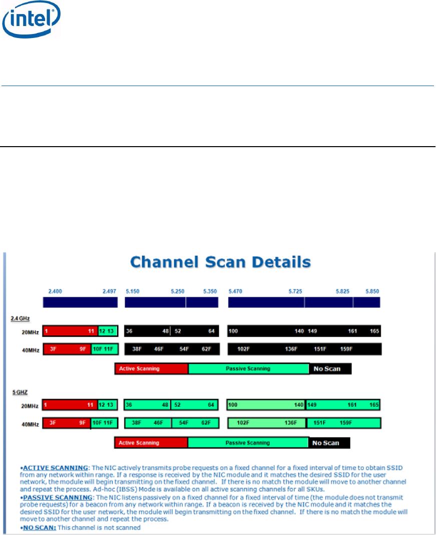
JacksonPeak1, JacksonPeak2, Marble Peak, Canyon Peak and Canyon Peak with Bluetooth
thermal is derived from its components MAC Baseband and the Radio chipset.
Table 19: JacksonPeak1, JacksonPeak2, Marble Peak, Canyon Peak and Canyon
Peak with Bluetooth Thermal Management
Name
Description
Thermal Shield
Performance
targets
JP1, JP2, MP, CyP and CyP w/Bluetooth shall have full performance at
shield temperatures up to 80ºC.
Testing conditions:
System environmental conditions:
1. High limit: ~50-55ºC under controlled environment
(Oven), with no air flow (inside a Box).
2. Low limit: 0ºC (starting point) under controlled
environment (Oven), with no air flow (inside a Box).
Thermal Silicon
protection
JP1, JP2, MP, CyP and CyP w/Bluetooth shall have silicon protection
mechanism (CT-Kill).
Thermal Silicon protection will not be activated below 95ºC T-shield
temperature.
5.2.1 Thermal Management and Critical Shutdown
The device thermal management cut off RF operation once a maximal temperature Critical
Temperature termination (CT-Kill) threshold has been exceeded. After cutoff point has been
reached, the RF remains at the off position until it cools down to Thermal Activation threshold,
during which the host cannot set the RF back to on.
5.2.2 Wi-Fi Thermal Throttling
The Product implements an autonomous Thermal throttling algorithm, to protect the Silicon
from permanent thermal damage, and ensure (as much as possible) connectivity even in hard
Thermal conditions.
Rx throttling Use the set the Power I
measurement
Tx throttling
CT Kill Shut down the card when reaching a Critical Temperature
Definitions:
Intel® Centrino® Wireless-N 105 (Canyon Peak)
Intel® Centrino® Wireless-N 135 (Canyon Peak w/Bluetooth)
Intel® Centrino® Wireless-N 2200 (Marble Peak)
Intel® Centrino® Wireless-N 2230 (Jackson Peak 1)
Intel® Centrino® Advanced-N 6235 (Jackson Peak 2)
Hardware Specification, Rev. 2.2
Intel Confidential
473288
32
1. T-ambient is the system Environment temperature in the card surrounding, with no air
flow; T-ambient is platform related value and can be different from Platform to
Platform; so it cannot be used for validation, see T-oven for comparable value
2. T-oven is the temperature in the immediate surroundings of the card when it is in
thermal oven (the temperate is constant in the Card surrounding, +/-1c) with NO Air-
Flow (the card is inside a closed box, inside the Oven)
3. T-Shield is the temperature on the Shield of the card (on the Shield) above the Radio
unit (The Hot-spot of the Card) this is the real deterministically measurable meter.
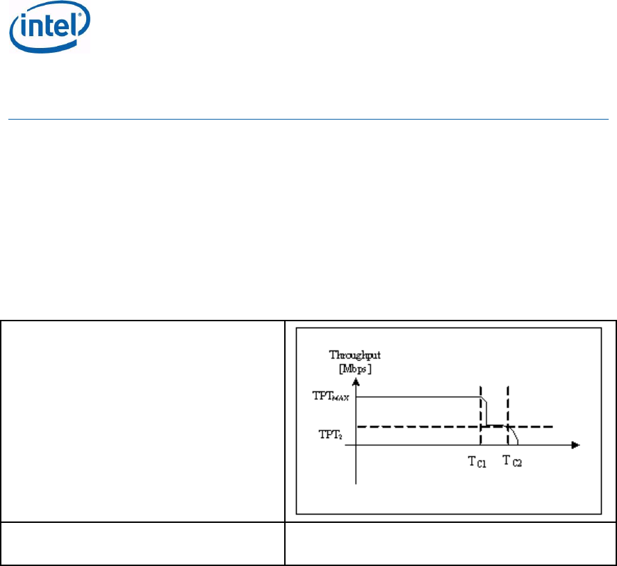
The Tx Throttling is guaranteeing the Wi-Fi functionality, and meet quality and reliability
requirements at thermal constraints While maximal performance (at high Shield temperature)
is reduced, as described in this section.
TPTmax – maximum throughput
TPT2 – the minimum throughput after the
throttling
Ts1 (appears as Tc1) – the shield
temperature that allows Max TPT, above
Ts1 max TPT may not be available
Ts2 (appears as Tc2) – the shield
temperature that allows Wi-Fi functionality,
above Ts2 Wi-Fi functionality may not be
available
To1/To2 are the equivalent Oven
temperature (assuming no Air flow) to Ts1
and Ts2
TPTmax = 300Mbps (Phy rate)
TPT2 = 54Mbps (Legacy Phy rate)
Ts1 = 80°c (To1 =~ 50°c, No air-flow)
Ts2 = 95°c (To2 =~ 70°c, No air-flow)

Intel® Centrino® Wireless-N 105 (Canyon Peak)
Intel® Centrino® Wireless-N 135 (Canyon Peak w/Bluetooth)
Intel® Centrino® Wireless-N 2200 (Marble Peak)
Intel® Centrino® Wireless-N 2230 (Jackson Peak 1)
Intel® Centrino® Advanced-N 6235 (Jackson Peak 2)
Hardware Specification, Rev. 2.2
Intel Confidential
473288
33
6 LED Indicators
JP1, JP2, CyP+Bluetooth products have 2 LEDs signals each: A Bluetooth LED, and a Wi-Fi
LED.
MP, CyP products have WiFi LED only (no Bluetooth supported)
The signals are open drain.
The Bluetooth LED functionality is as described below:
1. LED is OFF when the Bluetooth is in HW RF Kill (including idle, SW RF Kill = driver disable,
etc.).
2. LED is ON otherwise
The Wi-Fi LED functionality is as described below:
1. LED is OFF when the Wi-Fi is not powered
2. LED is ON when Powered, associated, and authenticated but not transmitting or receiving.
Intel® Centrino® Wireless-N 105 (Canyon Peak)
Intel® Centrino® Wireless-N 135 (Canyon Peak w/Bluetooth)
Intel® Centrino® Wireless-N 2200 (Marble Peak)
Intel® Centrino® Wireless-N 2230 (Jackson Peak 1)
Intel® Centrino® Advanced-N 6235 (Jackson Peak 2)
Hardware Specification, Rev. 2.2
Intel Confidential
473288
34
7 Regulatory Channel Support and Output
Power
7.1 Wi-Fi Channel Configuration
7.1.1 Channel Configuration Tables
See table below.
Table 20: JacksonPeak1, JacksonPeak2, Marble Peak, Canyon Peak and Canyon
eak with Bluetooth Scan Details
7.1.2 Antenna Gain for Product and Country Certifications
Intel uses the following antenna max gain for product and country certification:
3dBi for the 2.4Ghz
5dBi for the 5Ghz
Antenna gain above includes cable loses.
7.1.3 Maximum Legacy and MIMO RF Output Power
JacksonPeak1, JacksonPeak2, Marble Peak, Canyon Peak and Canyon Peak with Bluetooth TX
power shall be up-to16.5 dB assuming power is combined from all antennas.

Intel® Centrino® Wireless-N 105 (Canyon Peak)
Intel® Centrino® Wireless-N 135 (Canyon Peak w/Bluetooth)
Intel® Centrino® Wireless-N 2200 (Marble Peak)
Intel® Centrino® Wireless-N 2230 (Jackson Peak 1)
Intel® Centrino® Advanced-N 6235 (Jackson Peak 2)
Hardware Specification, Rev. 2.2
Intel Confidential
473288
35
7.1.4 Maximum Bluetooth Output Power
Output power for Bluetooth will be documented in future release of this EPS.
7.1.5 Output Power Restrictions (Main Geo’s)
Intel Reference antenna gain: Max. Antenna Gain 3dBi for 2.4GHz and 5dBi for 5GHz
7.1.6 Channel Configuration Tables / RF Output Power
The values listed in the power table (EEPROM table) below represent the target power for the
calibration process without antennae gain. This value has been verified to ensure margin to
the regulatory limit based on post EEPROM factory calibration measurements using a
diagnostic tool which operates the WLAN card at a ~99% DC (Duty Cycle) taken on both the
main and auxiliary antenna ports.
As part of the factory test process, Intel measures the output power of every card and any
cards that exceed the maximum limits (EEPROM + 1.5dB) will not pass factory test. While in
operation the card adjusts its TX power using a closed loop TX power calibration algorithm. To
do so, a power detector and temperature sensor are used. This algorithm adjusts the power to
within +/-1dB from the target, over temperature and voltage.
Intel uses the following antennae gain value for product and country certification work: 3dbi
for 2.4Ghz and 5dBi for 5GHz.
Intel also incorporates a lower limit to ensure that the compliance of the WLAN card is
maintained. The minimum limits are set by factory process. In MIMO mode this value is the
sum limit. Generally if sum=15 then Tx1 limit=12 dBm and Tx2 limit=12 dBm (exception for
some channels according to the table below).
Table 21: Canyon Peak, Canyon Peak + BT, CCK-Mode Configuration
Ch
Channel
center
in MHz
Active
Scanning
Allowed
IBSS
Allowed
MWT in
same
channel
mode
allowed
DFS
applicable
Uniform
Spreading
Tx
Power
(dBm)
CyP
Tx Power (dBm)
CyP+BT
1
2.412
Y
Y
Y
N
N
15
14.5
2
2.417
Y
Y
Y
N
N
15
15
3
2.422
Y
Y
Y
N
N
15
15
Country/Geo 2.4GHz 5.15 - 5.25GHz 5.25 - 5.35GHz 5.47 - 5.725GHz 5.725 - 5.85GHz
Output Power
Spectral Density
Canada 1W ** 50mW ** 250mW ** 250mW ** 1W **
Output Power
Canada 8dBm/3kHz ** 4dBm/MHz ** 11dBm/MHz ** 11dBm/MHz ** 8dBm/3kHz **
Spectral Density
EU Countries 100mW EIRP 200mW EIRP 200mW EIRP 1W EIRP N/A
Output Power
EU Countries 10dBm/MHz EIRP 10dBm/MHz EIRP 10dBm/MHz EIRP 17dBm/MHz EIRP N/A Spectral Density
Japan
12.14dBm/MHzEIRP
10dBm/MHz EIRP 10dBm/MHz EIRP 14dBm/MHz EIRP N/A Spectral Density
S. Korea *
10dBm/MHz **
No averaging
4dBm/MHz **
No Averaging
10dBm/MHz **
No Averaging
10dBm/MHz **
No Averaging
5.65 - 5.725GHz
Not Allowed
10dBm/MHz **
No Averaging
Channel 165 -5.825GHz
Not Allowed
Spectral Density
United States 1W ** 50mW ** 250mW ** 250mW ** 1W **
Output Power
United States 8dBm/3kHz ** 4dBm/MHz ** 11dBm/MHz ** 11dBm/MHz ** 8dBm/3kHz **
Spectral Density
** Allowance of up to a 6dBi antenna allowed, if antenna is > 6dBi output power must be reduced by 1dB per dBi of antenna gain
* Levels valid for 20 MHz channels. To be divided by 2 (reduce 3dB) for 40 MHz channels.

Intel® Centrino® Wireless-N 105 (Canyon Peak)
Intel® Centrino® Wireless-N 135 (Canyon Peak w/Bluetooth)
Intel® Centrino® Wireless-N 2200 (Marble Peak)
Intel® Centrino® Wireless-N 2230 (Jackson Peak 1)
Intel® Centrino® Advanced-N 6235 (Jackson Peak 2)
Hardware Specification, Rev. 2.2
Intel Confidential
473288
36
Ch
Channel
center
in MHz
Active
Scanning
Allowed
IBSS
Allowed
MWT in
same
channel
mode
allowed
DFS
applicable
Uniform
Spreading
Tx
Power
(dBm)
CyP
Tx Power (dBm)
CyP+BT
4
2.427
Y
Y
Y
N
N
15
15
5
2.432
Y
Y
Y
N
N
15
15
6
2.437
Y
Y
Y
N
N
15
15
7
2.442
Y
Y
Y
N
N
15
15
8
2.447
Y
Y
Y
N
N
15
15
9
2.452
Y
Y
Y
N
N
15
15
10
2.457
Y
Y
Y
N
N
15
15
11
2.462
Y
Y
Y
N
N
15
15
12
2.467
N
N
Y
N
N
15
15
13
2.472
N
N
Y
N
N
14.5
14
Note - Prior to Production phase the Tx Power setting is not set accurately;
Table 22: Canyon Peak, Canyon Peak + BT, OFDM-mode .11n
Configuration
Ch
Channel
center
in MHz
Active
Scanning
Allowed
IBSS
Allowed
MWT in
same
channel
mode
allowed
DFS
applicable
Uniform
Spreading
Tx
Power
(dBm)
CyP
Tx Power
(dBm)
CyP+BT
1
2.412
Y
Y
Y
N
N
13
13
2
2.417
Y
Y
Y
N
N
15
15
3
2.422
Y
Y
Y
N
N
15
15
4
2.427
Y
Y
Y
N
N
15
15
5
2.432
Y
Y
Y
N
N
15
15
6
2.437
Y
Y
Y
N
N
15
15
7
2.442
Y
Y
Y
N
N
15
15
8
2.447
Y
Y
Y
N
N
15
15
9
2.452
Y
Y
Y
N
N
15
15
10
2.457
Y
Y
Y
N
N
15
15
11
2.462
Y
Y
Y
N
N
12.5
13
12
2.467
N
N
Y
N
N
15
15
13
2.472
N
N
Y
N
N
13.5
13.5
Note - Prior to Production phase the Tx Power setting is not set accurately;

Intel® Centrino® Wireless-N 105 (Canyon Peak)
Intel® Centrino® Wireless-N 135 (Canyon Peak w/Bluetooth)
Intel® Centrino® Wireless-N 2200 (Marble Peak)
Intel® Centrino® Wireless-N 2230 (Jackson Peak 1)
Intel® Centrino® Advanced-N 6235 (Jackson Peak 2)
Hardware Specification, Rev. 2.2
Intel Confidential
473288
37
Table 23: Canyon Peak, Canyon Peak + BT, OFDM-mode .11n Configuration
Ch
Channel
center
in MHz
Active
Scanning
Allowed
IBSS
Allowed
MWT in
same
channel
mode
allowed
DFS
applicable
Uniform
Spreadin
g
Tx Power
(dBm)
CyP
Tx Power
(dBm)
CyP+BT
1
2.412
Y
Y
Y
N
N
12.5
12
2
2.417
Y
Y
Y
N
N
15
15
3
2.422
Y
Y
Y
N
N
15
15
4
2.427
Y
Y
Y
N
N
15
15
5
2.432
Y
Y
Y
N
N
15
15
6
2.437
Y
Y
Y
N
N
15
15
7
2.442
Y
Y
Y
N
N
15
15
8
2.447
Y
Y
Y
N
N
15
15
9
2.452
Y
Y
Y
N
N
15
15
10
2.457
Y
Y
Y
N
N
15
15
11
2.462
Y
Y
Y
N
N
12.5
12.5
12
2.467
N
N
Y
N
N
15
15
13
2.472
N
N
Y
N
N
13.5
13
(1,1) (5,-
1)
2.422
Y
Y
Y
N
N
9.5
9.5
(2,1) (6,-
1)
2.427
Y
Y
Y
N
N
10.5
10.5
(3,1) (7,-
1)
2.432
Y
Y
Y
N
N
12
11.5
(4,1) (8,-
1)
2.437
Y
Y
Y
N
N
11.5
12
(5,1) (9,-
1)
2.442
Y
Y
Y
N
N
11
11
(6,1)
(10,-1)
2.447
Y
Y
Y
N
N
10
10
(7,1)
(11,-1)
2.452
Y
Y
Y
N
N
9
9.5
(8,1)
(12,-1)
2.457
N
N
Y
N
N
14
14.5
(9,1)
(13,-1)
2.462
N
N
Y
N
N
13
13

Intel® Centrino® Wireless-N 105 (Canyon Peak)
Intel® Centrino® Wireless-N 135 (Canyon Peak w/Bluetooth)
Intel® Centrino® Wireless-N 2200 (Marble Peak)
Intel® Centrino® Wireless-N 2230 (Jackson Peak 1)
Intel® Centrino® Advanced-N 6235 (Jackson Peak 2)
Hardware Specification, Rev. 2.2
Intel Confidential
473288
38
Table 24: Jackson Peak2, CCK-Mode Configuration
Ch
Channel
center
in MHz
Active
Scanning
Allowed
IBSS
Allowed
MWT in
same
channel
mode
allowed
DFS
applicable
Uniform
Spreading
SISO
Ant A
Tx
Power
(dBm)
SISO Ant B
Tx Power
(dBm)
1
2.412
Y
Y
Y
N
N
14
14
2
2.417
Y
Y
Y
N
N
14.5
14
3
2.422
Y
Y
Y
N
N
14.5
14
4
2.427
Y
Y
Y
N
N
14.5
14
5
2.432
Y
Y
Y
N
N
14.5
14
6
2.437
Y
Y
Y
N
N
14.5
14
7
2.442
Y
Y
Y
N
N
14.5
14
8
2.447
Y
Y
Y
N
N
14.5
14
9
2.452
Y
Y
Y
N
N
14.5
14
10
2.457
Y
Y
Y
N
N
14.5
14
11
2.462
Y
Y
Y
N
N
14.5
14
12
2.467
N
N
Y
N
N
14.5
14
13
2.472
N
N
Y
N
N
14
14
Note - Prior to Production phase the Tx Power setting is not set accurately;
Table 25: Jackson Peak2, OFDM-mode non-.11n Configuration
Ch
Channel
center
in MHz
Active
Scanning
Allowed
IBSS
Allowed
MWT in
same
channel
mode
allowed
DFS
applicable
Uniform
Spreading
SISO
Ant A
Tx
Power
(dBm)
SISO Ant B
Tx Power
(dBm)
1
2.412
Y
Y
Y
N
N
12.5
12
2
2.417
Y
Y
Y
N
N
15
15
3
2.422
Y
Y
Y
N
N
15
15
4
2.427
Y
Y
Y
N
N
15
15
5
2.432
Y
Y
Y
N
N
15
15
6
2.437
Y
Y
Y
N
N
15
15
7
2.442
Y
Y
Y
N
N
15
15
8
2.447
Y
Y
Y
N
N
15
15
9
2.452
Y
Y
Y
N
N
15
15
10
2.457
Y
Y
Y
N
N
15
15

Intel® Centrino® Wireless-N 105 (Canyon Peak)
Intel® Centrino® Wireless-N 135 (Canyon Peak w/Bluetooth)
Intel® Centrino® Wireless-N 2200 (Marble Peak)
Intel® Centrino® Wireless-N 2230 (Jackson Peak 1)
Intel® Centrino® Advanced-N 6235 (Jackson Peak 2)
Hardware Specification, Rev. 2.2
Intel Confidential
473288
39
Ch
Channel
center
in MHz
Active
Scanning
Allowed
IBSS
Allowed
MWT in
same
channel
mode
allowed
DFS
applicable
Uniform
Spreading
SISO
Ant A
Tx
Power
(dBm)
SISO Ant B
Tx Power
(dBm)
11
2.462
Y
Y
Y
N
N
12.5
12
12
2.467
N
N
Y
N
N
15
15
13
2.472
N
N
Y
N
N
13
13
36
5.18
N
N
Y
N
Y
13
14
40
5.2
N
N
Y
N
Y
14.5
14.5
44
5.22
N
N
Y
N
Y
14.5
14.5
48
5.24
N
N
Y
N
Y
14.5
14.5
52
5.26
N
N
N
Y
N
14.5
14.5
56
5.28
N
N
N
Y
N
14.5
14.5
60
5.3
N
N
N
Y
N
14.5
14.5
64
5.32
N
N
N
Y
N
14.5
14.5
100
5.5
N
N
N
Y
N
14.5
14.5
104
5.52
N
N
N
Y
N
14.5
14.5
108
5.54
N
N
N
Y
N
14.5
14.5
112
5.56
N
N
N
Y
N
14.5
14.5
116
5.58
N
N
N
Y
N
14.5
14.5
120
5.6
N
N
N
Y
N
14.5
14.5
124
5.62
N
N
N
Y
N
14.5
14.5
128
5.64
N
N
N
Y
N
14.5
14.5
132
5.66
N
N
N
Y
N
14.5
14.5
136
5.68
N
N
N
Y
N
14.5
14.5
140
5.7
N
N
N
Y
N
14.5
14.5
149
5.745
N
N
Y
N
Y
14.5
14.5
153
5.765
N
N
Y
N
Y
14.5
14.5
157
5.785
N
N
Y
N
Y
14.5
14.5
161
5.805
N
N
Y
N
Y
14.5
14.5
165
5.825
N
N
Y
N
Y
14.5
14.5
Note - Prior to Production phase the Tx Power setting is not set accurately;

Intel® Centrino® Wireless-N 105 (Canyon Peak)
Intel® Centrino® Wireless-N 135 (Canyon Peak w/Bluetooth)
Intel® Centrino® Wireless-N 2200 (Marble Peak)
Intel® Centrino® Wireless-N 2230 (Jackson Peak 1)
Intel® Centrino® Advanced-N 6235 (Jackson Peak 2)
Hardware Specification, Rev. 2.2
Intel Confidential
473288
40
Table 26: Jackson Peak 2, OFDM-mode .11n Configuration
Ch
Channel
center
in MHz
Active
Scanning
Allowed
IBSS
Allowed
MWT in
same
channel
mode
allowed
DFS
applicable
Uniform
Spreadin
g
SISO
Ant A
Tx
Power
SISO
Ant B
Tx
Power
MIMO 2
Chains
Tx
Power
1
2.412
Y
Y
Y
N
N
11.5
11
11
2
2.417
Y
Y
Y
N
N
15
15
12
3
2.422
Y
Y
Y
N
N
15
15
12
4
2.427
Y
Y
Y
N
N
15
15
12
5
2.432
Y
Y
Y
N
N
15
15
12
6
2.437
Y
Y
Y
N
N
15
15
12
7
2.442
Y
Y
Y
N
N
15
15
12
8
2.447
Y
Y
Y
N
N
15
15
12
9
2.452
Y
Y
Y
N
N
15
15
12
10
2.457
Y
Y
Y
N
N
15
15
12
11
2.462
Y
Y
Y
N
N
11
11
10
12
2.467
N
N
Y
N
N
15
15
12
13
2.472
N
N
Y
N
N
13
13
11.5
36
5.18
N
N
Y
N
Y
12.5
13.5
11.5
40
5.2
N
N
Y
N
Y
14.5
14.5
11.5
44
5.22
N
N
Y
N
Y
14.5
14.5
11.5
48
5.24
N
N
Y
N
Y
14.5
14.5
11.5
52
5.26
N
N
N
Y
N
14.5
14.5
11.5
56
5.28
N
N
N
Y
N
14.5
14.5
11.5
60
5.3
N
N
N
Y
N
14.5
14.5
12
64
5.32
N
N
N
Y
N
14
14
12
100
5.5
N
N
N
Y
N
14.5
14.5
12
104
5.52
N
N
N
Y
N
14.5
14.5
11.5
108
5.54
N
N
N
Y
N
14.5
14.5
11.5
112
5.56
N
N
N
Y
N
14.5
14.5
11.5
116
5.58
N
N
N
Y
N
14.5
14.5
11.5
120
5.6
N
N
N
Y
N
14.5
14.5
12
124
5.62
N
N
N
Y
N
14.5
14.5
11.5
128
5.64
N
N
N
Y
N
14.5
14.5
11.5

Intel® Centrino® Wireless-N 105 (Canyon Peak)
Intel® Centrino® Wireless-N 135 (Canyon Peak w/Bluetooth)
Intel® Centrino® Wireless-N 2200 (Marble Peak)
Intel® Centrino® Wireless-N 2230 (Jackson Peak 1)
Intel® Centrino® Advanced-N 6235 (Jackson Peak 2)
Hardware Specification, Rev. 2.2
Intel Confidential
473288
41
Ch
Channel
center
in MHz
Active
Scanning
Allowed
IBSS
Allowed
MWT in
same
channel
mode
allowed
DFS
applicable
Uniform
Spreadin
g
SISO
Ant A
Tx
Power
SISO
Ant B
Tx
Power
MIMO 2
Chains
Tx
Power
132
5.66
N
N
N
Y
N
14.5
14.5
11.5
136
5.68
N
N
N
Y
N
14.5
14.5
11.5
140
5.7
N
N
N
Y
N
14.5
14.5
12
149
5.745
N
N
Y
N
Y
14.5
14.5
11.5
153
5.765
N
N
Y
N
Y
14.5
14.5
11.5
157
5.785
N
N
Y
N
Y
14.5
14.5
11.5
161
5.805
N
N
Y
N
Y
14.5
14.5
11.5
165
5.825
N
N
Y
N
Y
14.5
14.5
11.5
(1,1) (5,-
1)
2.422
Y
Y
Y
N
N
8
7.5
6
(2,1) (6,-
1)
2.427
Y
Y
Y
N
N
9
8
8
(3,1) (7,-
1)
2.432
Y
Y
Y
N
N
11
10.5
10
(4,1) (8,-
1)
2.437
Y
Y
Y
N
N
12
11
11
(5,1) (9,-
1)
2.442
Y
Y
Y
N
N
10
10
9
(6,1) (10,-
1)
2.447
Y
Y
Y
N
N
9.5
8.5
7.5
(7,1) (11,-
1)
2.452
Y
Y
Y
N
N
8.5
7.5
6.5
(8,1) (12,-
1)
2.457
N
N
Y
N
N
13
12
11.5
(9,1) (13,-
1)
2.462
N
N
Y
N
N
12
11.5
11
(36,1)
(40,-1)
5.19
N
N
Y
N
Y
10
10
8
(44,1)
(48,-1)
5.23
N
N
Y
N
Y
14
14
12
(52,1)
(56,-1)
5.27
N
N
N
Y
N
14
14
12
(60,1)
(64,-1)
5.31
N
N
N
Y
N
10
10.5
8.5
(100,1)
(104,-1)
5.51
N
N
N
Y
N
13
13
11

Intel® Centrino® Wireless-N 105 (Canyon Peak)
Intel® Centrino® Wireless-N 135 (Canyon Peak w/Bluetooth)
Intel® Centrino® Wireless-N 2200 (Marble Peak)
Intel® Centrino® Wireless-N 2230 (Jackson Peak 1)
Intel® Centrino® Advanced-N 6235 (Jackson Peak 2)
Hardware Specification, Rev. 2.2
Intel Confidential
473288
42
Ch
Channel
center
in MHz
Active
Scanning
Allowed
IBSS
Allowed
MWT in
same
channel
mode
allowed
DFS
applicable
Uniform
Spreadin
g
SISO
Ant A
Tx
Power
SISO
Ant B
Tx
Power
MIMO 2
Chains
Tx
Power
(108,1)
(112,-1)
5.55
N
N
N
Y
N
14.5
14.5
11.5
(116,1)
(120,-1)
5.59
N
N
N
Y
N
14.5
14.5
11.5
(124,1)
(128,-1)
5.63
N
N
N
Y
N
14.5
14.5
11.5
(132,1)
(136,-1)
5.67
N
N
N
Y
N
14.5
14.5
11.5
(149,1)
(153,-1)
5.755
N
N
Y
N
Y
14.5
14.5
11.5
(157,1)
(161,-1)
5.795
N
N
Y
N
Y
14.5
14.5
11.5
Table 27: Jackson Peak1, CCK-Mode Configuration
Ch
Channel
center in
MHz
Active
Scanning
allowed
IBSS
Allowed
MWT in
same
channel
mode
allowed
DFS
applicable
Uniform
Spreadin
g
SISO
Ant A
Tx
Power
(dBm
SISO
Ant B
Tx
Power
(dBm)
1
2.412
Y
Y
Y
N
N
13.5
13.5
2
2.417
Y
Y
Y
N
N
14.5
13.5
3
2.422
Y
Y
Y
N
N
14.5
13.5
4
2.427
Y
Y
Y
N
N
14.5
13.5
5
2.432
Y
Y
Y
N
N
14.5
13.5
6
2.437
Y
Y
Y
N
N
14.5
13.5
7
2.442
Y
Y
Y
N
N
14.5
13.5
8
2.447
Y
Y
Y
N
N
14.5
13.5
9
2.452
Y
Y
Y
N
N
14.5
13.5
10
2.457
Y
Y
Y
N
N
14.5
13.5
11
2.462
Y
Y
Y
N
N
14.5
13.5
12
2.467
N
N
Y
N
N
14.5
13.5
13
2.472
N
N
Y
N
N
14.5
13.5
Note - Prior to Production phase the Tx Power setting is not set accurately;

Intel® Centrino® Wireless-N 105 (Canyon Peak)
Intel® Centrino® Wireless-N 135 (Canyon Peak w/Bluetooth)
Intel® Centrino® Wireless-N 2200 (Marble Peak)
Intel® Centrino® Wireless-N 2230 (Jackson Peak 1)
Intel® Centrino® Advanced-N 6235 (Jackson Peak 2)
Hardware Specification, Rev. 2.2
Intel Confidential
473288
43
Table 28: Jackson Peak1 OFDM-mode non-.11n Configuration
Ch
Channel
center in
MHz
Active
Scanning
allowed
IBSS
Allowe
d
MWT in
same
channel
mode
allowed
DFS
applicable
Uniform
Spreading
SISO
Ant A
Tx
Power
(dBm)
SISO
Ant B
Tx
Power
(dBm)
1
2.412
Y
Y
Y
N
N
13.5
12.5
2
2.417
Y
Y
Y
N
N
15.0
14.5
3
2.422
Y
Y
Y
N
N
15.5
15.5
4
2.427
Y
Y
Y
N
N
15.5
15.5
5
2.432
Y
Y
Y
N
N
15.5
15.5
6
2.437
Y
Y
Y
N
N
15.5
15.5
7
2.442
Y
Y
Y
N
N
15.5
15.5
8
2.447
Y
Y
Y
N
N
15.5
15.5
9
2.452
Y
Y
Y
N
N
15.5
15.5
10
2.457
Y
Y
Y
N
N
15.5
15.5
11
2.462
Y
Y
Y
N
N
13.0
13.0
12
2.467
N
N
Y
N
N
15.5
15.5
13
2.472
N
N
Y
N
N
13.0
13.0
Note - Prior to Production phase the Tx Power setting is not set accurately;
Table 29: Jackson Peak1 OFDM-mode .11n Configuration
Ch
Chann
el
center
in MHz
Active
Scanning
allowed
IBSS
Allowed
MWT in
same
channel
mode
allowed
DFS
applicable
Uniform
Spreading
SISO
Ant A
Tx
Power
SISO
Ant B
Tx
Power
MIMO 2
Chains
Tx Power
1
2.412
Y
Y
Y
N
N
13.0
12.5
10.0
2
2.417
Y
Y
Y
N
N
14.5
14.5
12.0
3
2.422
Y
Y
Y
N
N
15.5
15.5
12.0
4
2.427
Y
Y
Y
N
N
15.5
15.5
12.0
5
2.432
Y
Y
Y
N
N
15.5
15.5
12.0
6
2.437
Y
Y
Y
N
N
15.5
15.5
12.0
7
2.442
Y
Y
Y
N
N
15.5
15.5
12.0
8
2.447
Y
Y
Y
N
N
15.5
15.5
12.0
9
2.452
Y
Y
Y
N
N
15.5
15.5
12.0
10
2.457
Y
Y
Y
N
N
15.5
15.5
12.0

Intel® Centrino® Wireless-N 105 (Canyon Peak)
Intel® Centrino® Wireless-N 135 (Canyon Peak w/Bluetooth)
Intel® Centrino® Wireless-N 2200 (Marble Peak)
Intel® Centrino® Wireless-N 2230 (Jackson Peak 1)
Intel® Centrino® Advanced-N 6235 (Jackson Peak 2)
Hardware Specification, Rev. 2.2
Intel Confidential
473288
44
Ch
Chann
el
center
in MHz
Active
Scanning
allowed
IBSS
Allowed
MWT in
same
channel
mode
allowed
DFS
applicable
Uniform
Spreading
SISO
Ant A
Tx
Power
SISO
Ant B
Tx
Power
MIMO 2
Chains
Tx Power
11
2.462
Y
Y
Y
N
N
12.0
12.0
10.5
12
2.467
N
N
Y
N
N
15.5
15.5
12.0
13
2.472
N
N
Y
N
N
13.0
13.0
11.5
(1,1)
(5,-1)
2.422
Y
Y
Y
N
N
9.5
8.5
7.0
(2,1)
(6,-1)
2.427
Y
Y
Y
N
N
10.5
9.5
8.0
(3,1)
(7,-1)
2.432
Y
Y
Y
N
N
11.5
11.0
9.5
(4,1)
(8,-1)
2.437
Y
Y
Y
N
N
12.5
13.0
11.5
(5,1)
(9,-1)
2.442
Y
Y
Y
N
N
12.0
12.5
11.0
(6,1)
(10,-1)
2.447
Y
Y
Y
N
N
10.5
11.0
9.5
(7,1)
(11,-1)
2.452
Y
Y
Y
N
N
9.5
9.5
7.5
(8,1)
(12,-1)
2.457
N
N
Y
N
N
14.0
14.0
12.0
(9,1)
(13,-1)
2.462
N
N
Y
N
N
13.5
13.5
12.0
Table 30: Marble Peak CCK-Mode Configuration
Ch
Channel
center in
MHz
Active
Scanning
allowed
IBSS
Allowed
MWT in
same
channel
mode
allowed
DFS
applicable
Uniform
Spreading
SISO Ant
A Tx
Power
(dBm
SISO Ant
B Tx
Power
(dBm)
1
2.412
Y
Y
Y
N
N
14.0
13.5
2
2.417
Y
Y
Y
N
N
14.5
14.0
3
2.422
Y
Y
Y
N
N
14.5
14.0
4
2.427
Y
Y
Y
N
N
14.5
14.0
5
2.432
Y
Y
Y
N
N
14.5
14.0
6
2.437
Y
Y
Y
N
N
14.5
14.0
7
2.442
Y
Y
Y
N
N
14.5
14.0
8
2.447
Y
Y
Y
N
N
14.5
14.0

Intel® Centrino® Wireless-N 105 (Canyon Peak)
Intel® Centrino® Wireless-N 135 (Canyon Peak w/Bluetooth)
Intel® Centrino® Wireless-N 2200 (Marble Peak)
Intel® Centrino® Wireless-N 2230 (Jackson Peak 1)
Intel® Centrino® Advanced-N 6235 (Jackson Peak 2)
Hardware Specification, Rev. 2.2
Intel Confidential
473288
45
Ch
Channel
center in
MHz
Active
Scanning
allowed
IBSS
Allowed
MWT in
same
channel
mode
allowed
DFS
applicable
Uniform
Spreading
SISO Ant
A Tx
Power
(dBm
SISO Ant
B Tx
Power
(dBm)
9
2.452
Y
Y
Y
N
N
14.5
14.0
10
2.457
Y
Y
Y
N
N
14.5
14.0
11
2.462
Y
Y
Y
N
N
14.5
14.0
12
2.467
N
N
Y
N
N
14.5
14.0
13
2.472
N
N
Y
N
N
14.0
13.5
Note - Prior to Production phase the Tx Power setting is not set accurately;
Table 31: Marble Peak OFDM-mode non-.11n Configuration
Ch
Channel
center in
MHz
Active
Scanning
allowed
IBSS
Allowed
MWT in
same
channel
mode
allowed
DFS
applicable
Uniform
Spreading
SISO
Ant A Tx
Power
(dBm)
SISO Ant B
Tx Power
(dBm)
1
2.412
Y
Y
Y
N
N
13.0
12.5
2
2.417
Y
Y
Y
N
N
15.0
14.5
3
2.422
Y
Y
Y
N
N
15.0
15.0
4
2.427
Y
Y
Y
N
N
15.0
15.0
5
2.432
Y
Y
Y
N
N
15.0
15.0
6
2.437
Y
Y
Y
N
N
15.0
15.0
7
2.442
Y
Y
Y
N
N
15.0
15.0
8
2.447
Y
Y
Y
N
N
15.0
15.0
9
2.452
Y
Y
Y
N
N
15.0
15.0
10
2.457
Y
Y
Y
N
N
15.5
15.5
11
2.462
Y
Y
Y
N
N
13.0
13.0
12
2.467
N
N
Y
N
N
15.0
15.0
13
2.472
N
N
Y
N
N
14.0
12.5
Note - Prior to Production phase the Tx Power setting is not set accurately;
Table 32: Marble Peak OFDM-mode .11n Configuration
Ch
Channel
center
in MHz
Active
Scanning
allowed
IBSS
Allowed
MWT in
same
channel
mode
allowed
DFS
applicable
Uniform
Spreading
SISO
Ant A
Tx
Power
SISO
Ant B
Tx
Power
MIMO
2
Chains
Tx
Power

Intel® Centrino® Wireless-N 105 (Canyon Peak)
Intel® Centrino® Wireless-N 135 (Canyon Peak w/Bluetooth)
Intel® Centrino® Wireless-N 2200 (Marble Peak)
Intel® Centrino® Wireless-N 2230 (Jackson Peak 1)
Intel® Centrino® Advanced-N 6235 (Jackson Peak 2)
Hardware Specification, Rev. 2.2
Intel Confidential
473288
46
Ch
Channel
center
in MHz
Active
Scanning
allowed
IBSS
Allowed
MWT in
same
channel
mode
allowed
DFS
applicable
Uniform
Spreading
SISO
Ant A
Tx
Power
SISO
Ant B
Tx
Power
MIMO
2
Chains
Tx
Power
1
2.412
Y
Y
Y
N
N
12.0
11.5
10.5
2
2.417
Y
Y
Y
N
N
14.5
14.0
12.0
3
2.422
Y
Y
Y
N
N
15.0
15.0
12.0
4
2.427
Y
Y
Y
N
N
15.0
15.0
12.0
5
2.432
Y
Y
Y
N
N
15.0
15.0
12.0
6
2.437
Y
Y
Y
N
N
15.0
15.0
12.0
7
2.442
Y
Y
Y
N
N
15.0
15.0
12.0
8
2.447
Y
Y
Y
N
N
15.0
15.0
12.0
9
2.452
Y
Y
Y
N
N
15.0
15.0
12.0
10
2.457
Y
Y
Y
N
N
15.5
15.5
12.0
11
2.462
Y
Y
Y
N
N
12.0
11.5
10.5
12
2.467
N
N
Y
N
N
15.0
15.0
12.0
13
2.472
N
N
Y
N
N
12.0
12.0
11.5
(1,1)
(5,-
1)
2.422
Y
Y
Y
N
N
9.0
8.5
7.0
(2,1)
(6,-
1)
2.427
Y
Y
Y
N
N
10.0
9.5
8.5
(3,1)
(7,-
1)
2.432
Y
Y
Y
N
N
11.5
10.5
9.5
(4,1)
(8,-
1)
2.437
Y
Y
Y
N
N
12.5
12.5
11.5
(5,1)
(9,-
1)
2.442
Y
Y
Y
N
N
11.5
11.5
11.0
(6,1)
(10,-
1)
2.447
Y
Y
Y
N
N
10.5
10.5
9.5
(7,1)
(11,-
1)
2.452
Y
Y
Y
N
N
9.5
9.0
8.5
(8,1)
(12,-
1)
2.457
N
N
Y
N
N
14.0
13.5
12.0

Intel® Centrino® Wireless-N 105 (Canyon Peak)
Intel® Centrino® Wireless-N 135 (Canyon Peak w/Bluetooth)
Intel® Centrino® Wireless-N 2200 (Marble Peak)
Intel® Centrino® Wireless-N 2230 (Jackson Peak 1)
Intel® Centrino® Advanced-N 6235 (Jackson Peak 2)
Hardware Specification, Rev. 2.2
Intel Confidential
473288
47
Ch
Channel
center
in MHz
Active
Scanning
allowed
IBSS
Allowed
MWT in
same
channel
mode
allowed
DFS
applicable
Uniform
Spreading
SISO
Ant A
Tx
Power
SISO
Ant B
Tx
Power
MIMO
2
Chains
Tx
Power
(9,1)
(13,-
1)
2.462
N
N
Y
N
N
13.0
13.0
11.5
7.2 Bluetooth Channel Configuration
Shall support Bluetooth 3.0 and should be able to scan and operate in all the standard legal
channels as defined by the Bluetooth-SIG.
The Bluetooth device supports power class 1 specifications of the Bluetooth SIG.
The channel hopping scheme supports AFH mechanism.
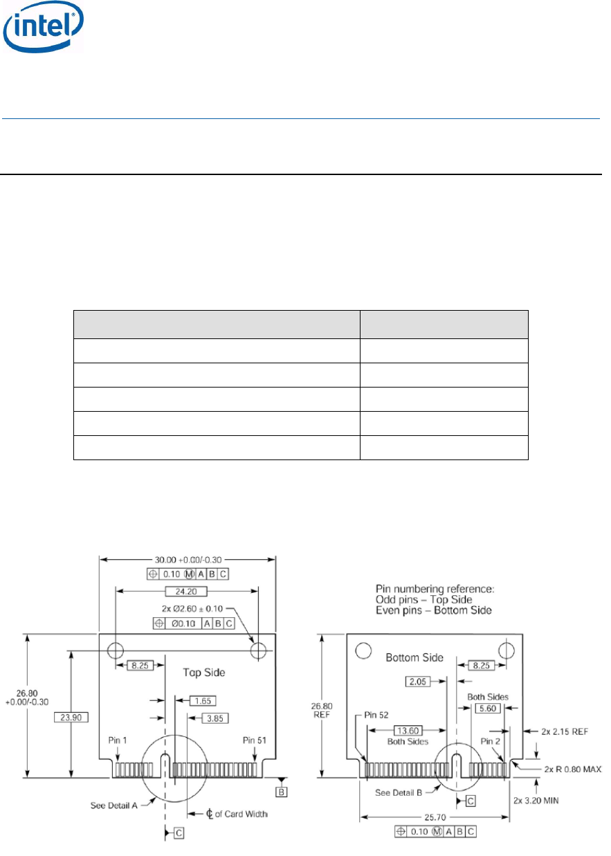
Intel® Centrino® Wireless-N 105 (Canyon Peak)
Intel® Centrino® Wireless-N 135 (Canyon Peak w/Bluetooth)
Intel® Centrino® Wireless-N 2200 (Marble Peak)
Intel® Centrino® Wireless-N 2230 (Jackson Peak 1)
Intel® Centrino® Advanced-N 6235 (Jackson Peak 2)
Hardware Specification, Rev. 2.2
Intel Confidential
473288
48
8 Mechanical Specifications
This section provides information about the mechanical specifications.
8.1 Half Mini Card Weight and Dimensions
The hardware is designed to comply with the dimensions specified in the PCI Express Mini
Card Electromechanical Specification. Table 21 lists the weights (grams) of Intel® Centrino®
Wireless Products.
Table 33: Intel® Centrino® Wireless Product Weights
Intel® Centrino® Wireless Product
Weight (g)
Marble Peak
3
Jackson Peak 1
3.45
Jackson Peak 2
3.7
Canyon Peak
2.9
Canyon Peak + Bluetooth
2.9
The dimensions in the Figure 6 and Figure 7 below include the top (which includes the shield)
and side views. The dimensions for Intel Centrino Wireless Products are:
26.80 mm x 30.00 mm x 2.4 mm Max (Top Side) / 1.35 mm Max (Bottom Side)
Figure 6: Top Side View of Half Mini Card Dimensions

Intel® Centrino® Wireless-N 105 (Canyon Peak)
Intel® Centrino® Wireless-N 135 (Canyon Peak w/Bluetooth)
Intel® Centrino® Wireless-N 2200 (Marble Peak)
Intel® Centrino® Wireless-N 2230 (Jackson Peak 1)
Intel® Centrino® Advanced-N 6235 (Jackson Peak 2)
Hardware Specification, Rev. 2.2
Intel Confidential
473288
49
Figure 7: Bottom Side View Half Mini Card Dimensions
Table 34: Z-height (Components on Board Location)
Form
Factor
Z-height(max)
HMC
CS – 2.4 mm
PS - 1.35 mm
8.2 Antenna Receptacles
A U.FL or equivalent micro coax connector will be used on the Jackson Peak1, Jackson Peak2,
Marble Peak, Canyon Peak and Canyon Peak with Bluetooth hardware and will be compatible
with other standard U.FL micro coax cable connectors.
The antenna connectors for will be labeled 1, and 2 on the label where:
Jackson Peak 1, Jackson Peak 2
1 = Main, left connector: Wi-Fi Tx/Rx only
2 = Aux, right connector: Wi-Fi Tx/Rx, Bluetooth Tx/Rx.
Marble Peak
1 = Main, left connector: Wi-Fi Tx/Rx
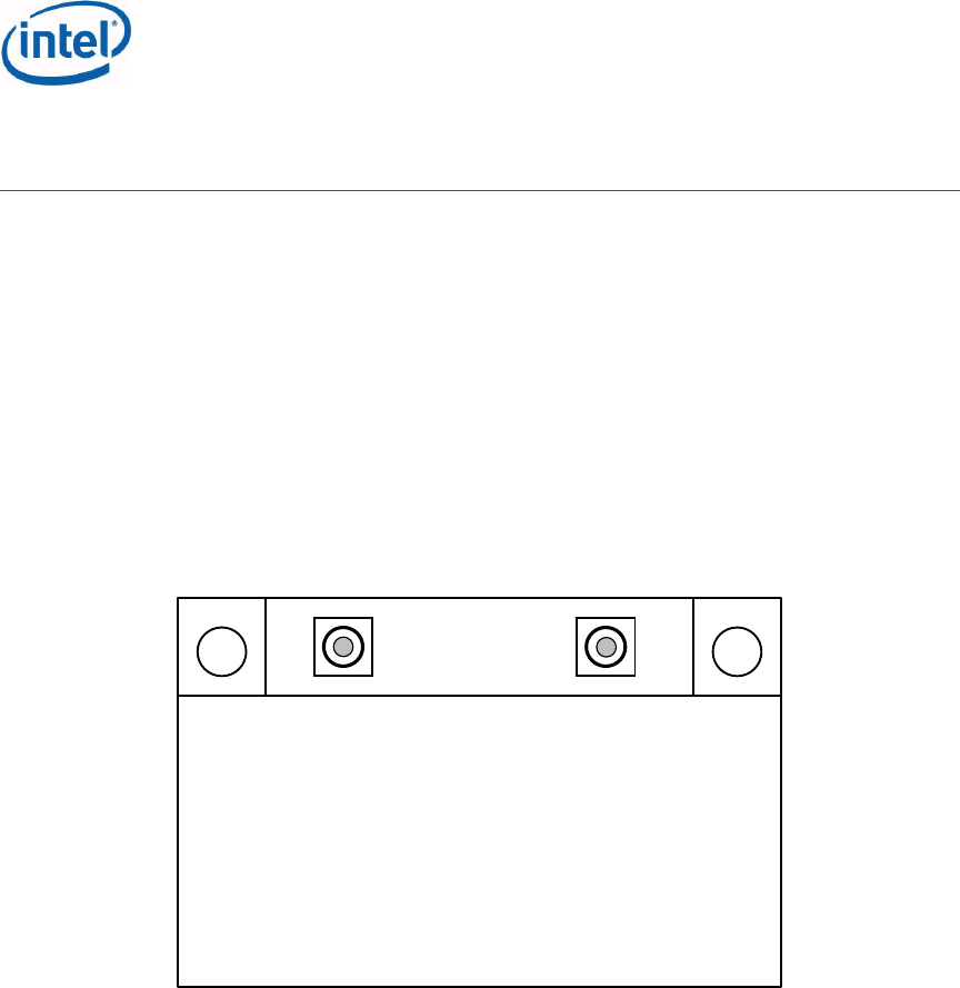
Intel® Centrino® Wireless-N 105 (Canyon Peak)
Intel® Centrino® Wireless-N 135 (Canyon Peak w/Bluetooth)
Intel® Centrino® Wireless-N 2200 (Marble Peak)
Intel® Centrino® Wireless-N 2230 (Jackson Peak 1)
Intel® Centrino® Advanced-N 6235 (Jackson Peak 2)
Hardware Specification, Rev. 2.2
Intel Confidential
473288
50
2 = Aux, right connector: Wi-Fi Tx/Rx
Canyon Peak
1 = Main, left connector: Wi-Fi Tx/Rx
2 = Aux, right connector: Wi-Fi Rx only
Canyon Peak + Bluetooth
1 = Main, left connector: Wi-Fi Tx/Rx
2 = Aux, right connector: Wi-Fi Rx only, Bluetooth Tx/Rx
Figure 8: Jackson Peak1, Jackson Peak2, Marble Peak, Canyon Peak and Canyon
Peak with Bluetooth
1 2
8.3 Connector Interface
The diagram in the figure below is excerpted from the PCI Express Mini Card
Electromechanical Specification, Rev. 1.2, published by the PCI-SIG, of which Intel
Corporation is a member. It contains the mechanical information for the Mini Card edge
connector. The following sections of this document detail
specification to improve the contact reliability for our customers. Measurement references
below are in millimeters.
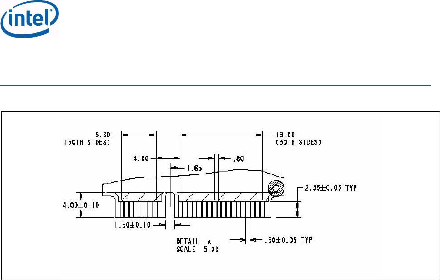
Intel® Centrino® Wireless-N 105 (Canyon Peak)
Intel® Centrino® Wireless-N 135 (Canyon Peak w/Bluetooth)
Intel® Centrino® Wireless-N 2200 (Marble Peak)
Intel® Centrino® Wireless-N 2230 (Jackson Peak 1)
Intel® Centrino® Advanced-N 6235 (Jackson Peak 2)
Hardware Specification, Rev. 2.2
Intel Confidential
473288
51
Figure 9: Mini Card Edge Connector

Intel® Centrino® Wireless-N 105 (Canyon Peak)
Intel® Centrino® Wireless-N 135 (Canyon Peak w/Bluetooth)
Intel® Centrino® Wireless-N 2200 (Marble Peak)
Intel® Centrino® Wireless-N 2230 (Jackson Peak 1)
Intel® Centrino® Advanced-N 6235 (Jackson Peak 2)
Hardware Specification, Rev. 2.2
Intel Confidential
473288
52
9 Environmental Specifications
The following tables provide operating condition and maximum rating requirements for the
Jackson Peak1, Jackson Peak2, Marble Peak, Canyon Peak and Canyon Peak with Bluetooth
hardware.
Table 35: Operational Conditions
Environment
Limits
Operating Temperature
0 ºC – 80 ºC
Note: Environmental temperature is measured on the card shield cover.
Table 36: Storage conditions
Environment
Limits
Storage Temperature
(Non-Operational)
-40 ºC to 70 ºC
Humidity (Non-
Operational)
50% to 90% non-condensing (at temperatures of
25 ºC to 35 ºC)
Jackson Peak1, Jackson Peak2, Marble Peak, Canyon Peak and Canyon Peak with Bluetooth
temperature conditions for storage (packaged) in warehouse are -40c to +70c, which should
be divided into two parts:
1. Temperature condition for storage (packaged) in warehouse Maximum 40°C Up to 6
months.
2. Temperature condition for shipping /storage for short duration high temperature exposure
Maximum 70°C Up to 24 hours.

Intel® Centrino® Wireless-N 105 (Canyon Peak)
Intel® Centrino® Wireless-N 135 (Canyon Peak w/Bluetooth)
Intel® Centrino® Wireless-N 2200 (Marble Peak)
Intel® Centrino® Wireless-N 2230 (Jackson Peak 1)
Intel® Centrino® Advanced-N 6235 (Jackson Peak 2)
Hardware Specification, Rev. 2.2
Intel Confidential
473288
53
10 Safety
The following regulatory and safety information is subject to change.
Table 37: Wi-Fi Safety and Regulatory USA
USA
Requirements
Criteria
EMI
FCC Part 15, Subpart B, Class B (CISPR 22 Limits at
10m)
RF
FCC Part 15, Subpart C (Sections 15.205, 15.207,
15.209, & 15.247)
FCC Part 15, Subpart E (Section 15.407)
Safety
UL 60950-1
Table 38: Wi-Fi Safety and Regulatory Europe
Europe
Requirements
Criteria
EMC
EN301489-1, EN 301489-17
RF
EN300 328 v.1.7.1 & EN301-893 v.1.5.1 as DFS slave
terminal
Safety
EN60950-1 via CB Report (IEC60950-1)
R&TTE Health Requirement article 1(a) referring to the
EU EN50371
Table 39: Wi-Fi Safety and Regulatory Japan
Japan
Requirements
Criteria
EMI
VCCI Class B
RF
STD T66, STD T71, ARIB W52, W53, W56
Safety
EN60950-1 via CB Report (IEC60950-1)
R&TTE Health Requirement article 1(a) referring to the
EU EN50371
Table 40: Wi-Fi Safety and Regulatory Australia / New Zealand
Australia /
New Zealand
Requirements
Criteria
EMC
EU Test reports.
RF
Radio communications (EMR) Standard 2003
Safety
CB Cert. & Report (IEC60950-1)

Intel® Centrino® Wireless-N 105 (Canyon Peak)
Intel® Centrino® Wireless-N 135 (Canyon Peak w/Bluetooth)
Intel® Centrino® Wireless-N 2200 (Marble Peak)
Intel® Centrino® Wireless-N 2230 (Jackson Peak 1)
Intel® Centrino® Advanced-N 6235 (Jackson Peak 2)
Hardware Specification, Rev. 2.2
Intel Confidential
473288
54
Table 41: Wi-Fi Safety and Regulatory Other Geographies
Other
Geographies
Requirements
Criteria
Priority 2
Countries
To be covered in MWG Regulatory WW Country
Coverage
Priority 3
Countries
To be covered in MWG Regulatory WW Country
Coverage
Note: Regulatory pre-scans and certification are tested using a Combo Bluetooth/Wi-Fi
reference antenna

Intel® Centrino® Wireless-N 105 (Canyon Peak)
Intel® Centrino® Wireless-N 135 (Canyon Peak w/Bluetooth)
Intel® Centrino® Wireless-N 2200 (Marble Peak)
Intel® Centrino® Wireless-N 2230 (Jackson Peak 1)
Intel® Centrino® Advanced-N 6235 (Jackson Peak 2)
Hardware Specification, Rev. 2.2
Intel Confidential
473288
55
11 Certification Requirements
A preliminary list of certification requirements includes the following:
Table 42: Jackson Peak1, Jackson Peak2, Marble Peak, Canyon Peak and Canyon
Peak with Bluetooth Certification Requirements
Requirement
Detail Description
Bluetooth USB-IF
All products shall pass chapter 9 of USB-IF in order get
USB-IF certification for Microsoft Windows8 logo
requirements
Mini CEM add-in
card
Mini CEM add-in card PCI-SIG conformance1
WHQL
Microsoft Windows XP, Microsoft Windows Vista and
Microsoft Windows 7 WDKWHQL tests for networking
device
Wi-Fi certification
The same as Intel® Centrino 6200 Series certification
Bluetooth
certifications
Bluetooth SIG certification for the device and the SW
stack delivered with it.
1 Not submitted to external certification lab for PCI-SIG specification compliance, however PCI
compliance is tested internally (within Intel Corporation).

Intel® Centrino® Wireless-N 105 (Canyon Peak)
Intel® Centrino® Wireless-N 135 (Canyon Peak w/Bluetooth)
Intel® Centrino® Wireless-N 2200 (Marble Peak)
Intel® Centrino® Wireless-N 2230 (Jackson Peak 1)
Intel® Centrino® Advanced-N 6235 (Jackson Peak 2)
Hardware Specification, Rev. 2.2
Intel Confidential
473288
56
12 Antenna Design Considerations
12.1 Antenna Port Impedance
Nominal antenna port impedance specification is 50 ohm.
12.2 Antennas Frequency Bands
Refer to Chief River Platform Design Guide.
12.3 Antenna Gain
Refer to Chief River Platform Design Guide.
12.4 Antenna Characteristics
Refer to Chief River Platform Design Guide.

Intel® Centrino® Wireless-N 105 (Canyon Peak)
Intel® Centrino® Wireless-N 135 (Canyon Peak w/Bluetooth)
Intel® Centrino® Wireless-N 2200 (Marble Peak)
Intel® Centrino® Wireless-N 2230 (Jackson Peak 1)
Intel® Centrino® Advanced-N 6235 (Jackson Peak 2)
Hardware Specification, Rev. 2.2
Intel Confidential
473288
57
13 HW RF Kill Considerations
The Wi-Fi RF Kill is supported via Pin #20 (W_Disable), and this is similar to previous
products.
The Bluetooth RF Kill is supported via Pin #51 (W_Disable#2)
Since both RF Kill signals are active low, and there is an internal pull up this means that they
can be left not connected, and both Wi-Fi and Bluetooth will be enabled.
To disable the BluetoothVil = 0.0v [+/-0.3]) should be applied to the
W_disable#2 pin.
To disable the Wi-Vil = 0.0v [+/-0.3]) should be applied to the W_disable# pin.
In order to test Intel Wireless on legacy platforms (prior to Huron River), the W_disable#2 pin
If for any reason, the W_disable#2 pin tform then Bluetooth
would be disabled.

Intel® Centrino® Wireless-N 105 (Canyon Peak)
Intel® Centrino® Wireless-N 135 (Canyon Peak w/Bluetooth)
Intel® Centrino® Wireless-N 2200 (Marble Peak)
Intel® Centrino® Wireless-N 2230 (Jackson Peak 1)
Intel® Centrino® Advanced-N 6235 (Jackson Peak 2)
Hardware Specification, Rev. 2.2
Intel Confidential
473288
58
Appendix A References and Acronyms
A.1 Document References
Document Name
Location
Wireless LAN MAC and PHY Specifications, 802.11b
http://standards.ieee.org/getieee802/download/
802.11b-1999_Cor1-2001.pdf
Wireless LAN MAC and PHY Specifications, 802.11g
http://standards.ieee.org/getieee802
Wireless LAN MAC and PHY Specifications, 802.11a
http://standards.ieee.org/getieee802
Wireless LAN MAC and PHY Specifications, 802.11n-
2009
http://standards.ieee.org/getieee802
PCI Express Base Specification, Rev 1.2
http://www.pcisig.com/specifications/pciexpress
PCI Express Card Electromechanical Specification, Rev
1.2
http://www.pcisig.com/specifications/pciexpress
PCI Express Mini Card Electromechanical Specification,
Rev 1.2
http://www.pcisig.com/specifications/pciexpress
PCI Local Bus Specification Rev. 2.3
http://www.pcisig.com/specifications/convention
al/conventional_pci
PCI Bus Power Management Interface Specification Rev
1.1
http://www.pcisig.com/specifications/convention
al/pci_bus_power_management_interface
Advanced Configuration and Power Interface Version 3.0
http://www.acpi.info/spec.htm
Microsoft Hardware Device Class Power Management
Specification
http://www.microsoft.com/whdc/hwdev/resource
s/specs/pmref/default.mspx
A.2 Acronyms and Definitions
The following list defines key terms and acronyms used in this document.
Term
Definition
ACPI
Advanced Configuration Power Interface
ADC
Analog-to-Digital Converter
AES
Advanced Encryption Standard
AGC
Automatic Gain Control
AP
Access Point
BCWS
Business Class Wireless Suite
BLE
Bluetooth low energy technology
BPF
Band Pass Filter
CCK
Complementary Code Keying
BT
Bluetooth

Intel® Centrino® Wireless-N 105 (Canyon Peak)
Intel® Centrino® Wireless-N 135 (Canyon Peak w/Bluetooth)
Intel® Centrino® Wireless-N 2200 (Marble Peak)
Intel® Centrino® Wireless-N 2230 (Jackson Peak 1)
Intel® Centrino® Advanced-N 6235 (Jackson Peak 2)
Hardware Specification, Rev. 2.2
Intel Confidential
473288
59
Term
Definition
DAC
Digital-to-Analog Converter
DBPSK
Differential Bi-phase Shift Keying
DC
Direct Current
DMA
Direct Memory Access
DQPSK
Differential Quadrature Phase Shift Keying
DSP
Digital Signal Processor
DSSS
Direct Sequence Spread Spectrum
D - States
ACPI (Advanced Control and Power Interface) Peripheral Device
power states
ETSI
European Telecommunication Standards Institute
GI
Guard Interval
GND
Ground Signal
GUI
Graphical User Interface
HID
Human Interface Devices
IC
Integrated Circuit
IEEE
Institute of Electrical and Electronics Engineers
IF
Intermediate Frequency
Intel® AMT
Intel® Active Management Technology
I/O
Input/Output
I/Q
In-Phase/Quadrature Phase
ISM
Industrial, Scientific, and Medical (Band)
LED
Light Emitting Diode (Signal)
LNA
Low Noise Amplifier
L – States
ASPM (Active State Power Management). Link States is a hardware
based capability to manage the PCI Express Link between the root
device on the system board and the Mini Card.
MAC
Media Access Control
MCS
Modulation Coding Scheme
Mbps
Megabits Per Second
MIMO
Multiple Input, Multiple Output
MOW
Most of World
MS
Mobile Station
NC
Not Connected (Signal)
NIC
Network Interface Card
OFDM
Orthogonal Frequency Division Multiplexing

Intel® Centrino® Wireless-N 105 (Canyon Peak)
Intel® Centrino® Wireless-N 135 (Canyon Peak w/Bluetooth)
Intel® Centrino® Wireless-N 2200 (Marble Peak)
Intel® Centrino® Wireless-N 2230 (Jackson Peak 1)
Intel® Centrino® Advanced-N 6235 (Jackson Peak 2)
Hardware Specification, Rev. 2.2
Intel Confidential
473288
60
Term
Definition
OTA
Over the Air
PA
Power Amplifier
PCI
Peripheral Component Interconnect
PCI Express Mini
Card
PCI Express Mini Card mobile form factor
PHY
Physical Layer
PLCP
Physical Layer Convergence Protocol
PLL
Phase Locked Loop
PSP
Power Save Polling
QoS
Quality of Service
RF
Radio Frequency
RISC
Reduced Instruction Set Computing
ROW
Rest of World
Rx
Receive
SISO
Single Input, Single Output. Antenna implementation using a single
antenna at a given time versus a MIMO (Multiple Input, Multiple
Output) antenna configuration
SKU
Stock Keeping Unit
SRAM
Static Random Access Memory
STBC
Space Time Block Codes
TBTT
Target Beacon Transmission Time
Tx
Transmit
Wake-up
A mechanism used by a component to request the reapplication of
main power when in the L2 Link state. Two such mechanisms are
defined in the PCIe Base Specification: Beacon and WAKE#. This
specification requires the use of WAKE# for the Mini Card and system
board that supports wakeup functionality.
WCS
Wireless Coexistence System for Bluetooth*
WEP
Wired Equivalent Privacy
WFA
Wi-Fi Alliance*
WHQL
(Microsoft) Windows Hardware Quality Labs
Wi-Fi
Wireless Fidelity
WLAN
Wireless Local Area Network
XTAL
40-MHz Crystal
Federal Communication Commission Interference Statement
This device complies with Part 15 of the FCC Rules. Operation is subject to the
following two conditions: (1) This device may not cause harmful interference, and
(2) this device must accept any interference received, including interference that may
cause undesired operation.
This equipment has been tested and found to comply with the limits for a Class B
digital device, pursuant to Part 15 of the FCC Rules. These limits are designed to
provide reasonable protection against harmful interference in a residential installation.
This equipment generates, uses and can radiate radio frequency energy and, if not
installed and used in accordance with the instructions, may cause harmful interference
to radio communications. However, there is no guarantee that interference will not
occur in a particular installation. If this equipment does cause harmful interference to
radio or television reception, which can be determined by turning the equipment off
and on, the user is encouraged to try to correct the interference by one of the
following measures:
- Reorient or relocate the receiving antenna.
- Increase the separation between the equipment and receiver.
- Connect the equipment into an outlet on a circuit different from that
to which the receiver is connected.
- Consult the dealer or an experienced radio/TV technician for help.
FCC Caution: Any changes or modifications not expressly approved by the party
responsible for compliance could void the user's authority to operate this equipment.
This transmitter must not be co-located or operating in conjunction with any other
antenna or transmitter.

Radiation Exposure Statement:
This equipment complies with FCC radiation exposure limits set forth for an
uncontrolled environment. This module can be use with Getac Notebook: B320 or
similar platform with similar dimension, antenna location and RF characteristic.
This device is intended only for OEM integrators under the following conditions:
1) The antenna must be installed at same location as tested in the certification filing.
2) The transmitter module may not be co-located with any other transmitter or
antenna.
3) For portable usage condition, this module has been SAR evaluated in Getac
Notebook: B320 host with compliance result and can be used with this specific
hast as described in the certification filing. Other host or platform needs separate
approval.
As long as 3 conditions above are met, further transmitter test will not be required.
However, the OEM integrator is still responsible for testing their end-product for any
additional compliance requirements required with this module installed
Note: Operations in the 5.15-5.25GHz band are restricted to indoor usage only.
IMPORTANT NOTE: In the event that these conditions can not be met (for example
certain laptop configurations or co-location with another transmitter), then the FCC
authorization is no longer considered valid and the FCC ID can not be used on the
final product. In these circumstances, the OEM integrator will be responsible for
re-evaluating the end product (including the transmitter) and obtaining a separate FCC
authorization.
End Product Labeling
The final end product must be labeled in a visible area with the following: “Contains
FCC ID: QYL6235”. The grantee's FCC ID can be used only when all FCC
compliance requirements are met.
Manual Information To the End User
The OEM integrator has to be aware not to provide information to the end user
regarding how to install or remove this RF module in the user’s manual of the end
product which integrates this module.
The end user manual shall include all required regulatory information/warning as
show in this manual.