Getech Technology ESP8266 WIFI module User Manual
Shenzhen Getech Technology Co.,Ltd. WIFI module
User Manual
WiFi Module Instruction
Contents
1. Overview ................................................................................................................................... 1
1.1 Product Name: ESP8266 WiFi Module ............................................................................ 1
1.2 Main Features .................................................................................................................... 1
1.3 The Structure of ESP8266 WiFi Module .......................................................................... 1
1.4 Applications ...................................................................................................................... 2
1.5 Operating Environment ..................................................................................................... 3
1.6 Operating requirements ..................................................................................................... 3
2. How to use ESP8266 WiFi Module .......................................................................................... 3
2.1 Define the Interface between ESP8266 WiFi Module and 3D Printer’s Control Board ... 3
2.2 Define the Interactive Interface between ESP8266 WiFi module and the Server ............. 7
2.3 Define the Interactive Interface between ESP8266 WiFi Module and the mobile (Config.
mode) ........................................................................................................................................ 8
2.4 The Interface between Database and the Console ............................................................. 9
2.5 Define the Interface for Uploading Files ......................................................................... 10
1
1. Overview
1.1 Product Name: WIFI module
Trade Mark:
Model No.: ESP8266
1.2 Main Features
ESP8266 is an integrated and systematic solution to WiFi network. Users can use
mobile devices as the station to connect to softAP port of ESP8266 so as to control it
by via router network connectivity. It is easy to add ESP8266 to any
microcontroller-based design via the UART port and upload and download data to the
cloud server. Via the cloud, users could utilize mobile devices to monitor the working
status of the microcontroller and send instructions to it.
ESP8266 WiFi module works as the network interface between 3D printer and
mobile devices. This WiFi module, adhering to the 802.11 network protocol, supports
the communication between 3D printer and the Geeetech self-developed 3D printing
App --- EasyPrint 3D. In addition, other network endpoints based on the 802.11
network protocol could be compatible with this WiFi module.
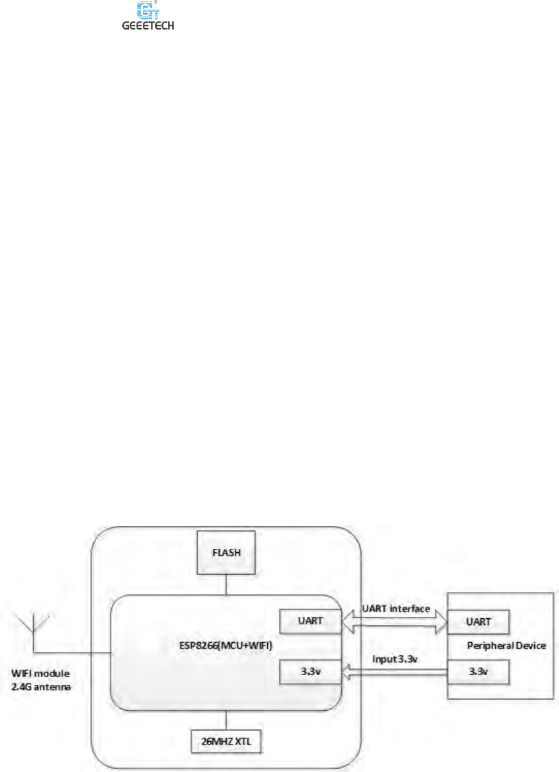
1.3 The Structure of ESP8266 WiFi Module
Figure 1. Functional Block Diagram
ESP8266 WiFi module comes with a built-in Tensilica L106, 32 bit
microcontroller, having ultra-low power 16 bit RSIC. The speed of CPU clock is at
Note:The manual will be released after granted the FCC authorization.
2
80MHZ, with its upper limit as 160MHZ. ESP8266 uses the external SPI Flash to
store user program, with the memory of 1MB. Based on an external crystal, the
crystal oscillator of ESP8266 could generate Radio Frequency clock to drive the
mixer to down-convert the radio frequency signal and transform it as digital signal.
The orthogonal baseband signal would be up-scaled to 2.4GHz. ESP8266 supports
TCP/IP protocol, 802.11 b/g/n/e/I WLAN MAC protocol and the Wi-Fi Direct
standard. The two universal asynchronous receiver transmitters of the hardware could
communicate with the microcontroller in a convenient way.
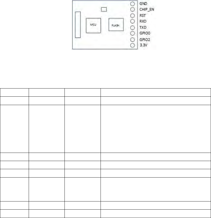
Figure 2. Interface Definition
The pin assignments as shown in Figure 1-1
Pin
Name
Type
Function
1
GND
P
Ground wire
2
CHIP_EN
I/O
Chip Enable Terminal:The chip works normally at
the high level, and closes at the low level with
low current 。
3
RST
I/O
External reset signal (works normally at low level)
4
RXD
I/O
The RX pin of UART,the TX pin of external circuit
5
TXD
I/O
The TX pin of UART,theRX pin of external circuit
6
GPIO0
I/O
FLASH start at the high level; System upgrade at the low
level (able to upgrade internal firmware via the serial
port)
7
GPIO2
I/O
8
3.3V
P
Digital power supply 3.3V
1.4 Applications
ESP 8266 WiFi module can be apply to different fields, such as 3D printer,

3
domestic appliances, home automation, smart socket and lamp, industrial wireless
control system, sensor networks, wearables, wireless position sensing devices, etc.
1.5 Operating Environment
1.6 Operating requirements
a. Stable voltage for the power supply module
b. The upper limit voltage for GPIO is 3.6V. In case that the voltage goes beyond
3.6V, you need the buck circuit to drive ESP8266 WiFi module. Or there
would be damages for the GPIO interface.
c. If you choose to use LDO to transform the voltage, make surethat the input
and output voltages are large enough. The decoupling capacitor should be
place beside the module and the equivalent resistance should be low enough.
When using DC-DC to power up the module, please, if necessary, add the LC
filter circuit.
d. Since the RF of ESP8266 WiFi module and the digital circuit are of high
integrity, and high-level current is needed for FR self-calibration when the
power is on, please ensure that the current could reach 5000 Ma to avoid
instantaneous voltage drop.
e. We don’t recommend you to use un-calibrated battery to power up the module,
since the FR circuit would be affected by temperature and voltage fluctuation.
2. How to use ESP8266 WiFi Module
2.1 Define the Interface between ESP8266 WiFi Module and 3D
Printer’s Control Board
Connect the Server
Instruction
format
Connect to srd;devicename;serverIP;
Description
Inform the WiFi module of the user name and password, the router’s name and the
IP address of the server.
Need to reset the WiFi module before sending this instruction.

4
Log on to the Server
Instruction
Format
deviceord;login\r\n
Description
Inform the WiFi module to log in with the user name and password
Enter the Configuration Mode
Instruction
format
set ap\r\n
Instruction
format
get name ssid:password; serverIP;\r\n
Data Transmission
ESP8266 WiFi module adopts the transparent pass-through approach to transmit
data. However, the transmission speed of WiFi module is limited. So the data
packages could only be transmitted one by one.
Transmit one data package:
Instruction
format
xxxxxxxx\n
Description
Xxxxxxxx as the content; “\n”as the end signal. WiFi module regards xxxxxx as one
data package.
The Network Disconnection Situation
When the network is disconnected (in case of weak WiFi signal or abnormal
logout), WiFi module will send one instruction to the control board every 3 seconds.
The instruction is as follows:
Instruction
format
Description
When the network is disconnected, WiFi module will send one instruction to the
control board every 3 seconds. Meanwhile, the control board should restart the
WiFi module.
Send the reconnection command, if necessary.

5
Complete the gcode. Instruction
1) M20 reads SD card file list.
2) Print the select SD card gcode file.
3) Send gcode file to SD card.
Inquire temp
M105
ok B:16.8 /0.0 T0:17.5 /0.0 T1:0.0 /0.0 T2:0.0 /0.0
F0:200 S:100 @:0 B@:0.
Home X axis
N79 G28 X0*101
X:280.000.ok
Home Y axis
N80 G28 Y0*98
Y:160.000.ok
Home Z axis
N81 G28 Z0*96
Z:157.000.ok
Home all the
axes
N82 G28*41
X:280.000.Y:160.000.Z:157.000.ok
Move X axis
by -1mm
N86 G91*47
N87 G1 X-1 F4800*25
N88 G90*32
ok
ok
ok
Move X axis
by 1mm
N101 G91*17
N102 G1 X1 F4800*8
N103 G90*18
ok
ok
ok
Move Y axis
by -1mm
N110 G91*17
N111 G1 Y-1 F4800*38
N112 G90*18
ok
ok
ok
Move Z axis
by -1mm
N113 G91*18
N114 G1 Z-1 F100*29
N115 G90*21
ok
ok
ok
.N116 G91*23
N117 G1 E-10 F1800*9

6
Move the
extruder by
-10mm
N118 G90*24
ok
ok
ok
Set printing
speed as
141%
N119 M220 S141*109
ok
Set fan speed
as 230
(0~255)
N180 M106 S230*111
ok
Switch off
the fan
N181 M107*45
ok
Set hotbed
temp as 55℃
N182 M140 S55*94
ok
Set the temp
of T0
(Extruder 1)
as 200℃
N184 M104 T0 S200*46
ok
Inquire
device info
N11 M115*22
FIRMWARE_NAME:V1.08 PROTOCOL_VERSION:V1.0
MACHINE_TYPE:D200 EXTRUDER_COUNT:2
UUID:16S1123D2000010.
Switch off/
Enter the idle
mode
N15 M81*46
ok
Switch on/
Wake up
N15 M80*46
ok
Delete SD
card file
N15 M30*46
ok
List SD card
N15 M20*46
Return to the file list, ok
Return a “end” command as “list end”
Select file
and start SD
print
N15 M23 foot.gcode(file name) *46
ok
Start/resume
SD print
N15 M24*46
ok
Pause SD
print
N15 M25*46
ok
Disable
motor

7
Enable
Motor
Inquire the
status of 3D
printer
M21
printer_priile:xxxx.gcode;precent:60%;used_time:20mm;
printer_pae:xxxx.gcode;precent:60%;used_time:20mm;
printer_idle;
Notifications
upon
finishing
printing
printer_fi:xxx.gcode;used_time:60mm;
Notifications
when
filament runs
out
printer_ lament;
Event: finish printing, pause, filament running out/ fracturing, 3D printer is
on-line, 3D printer is off-line; printing, etc.
2.2 Define the Interactive Interface between ESP8266 WiFi
module and the Server
Log in
Instruction
format
yy_xxx:nnnn;login
Description
User name: password
Users connect the 3D printer with the server
Instruction
format
xxx;call;yyy
Description
User xxx visits 3D printer yyy: Inform the WiFi module of 3D printer that the data
returned will be transferred to user xxx.
Inquire on-line devices
Instruction
format
xxx;get live
Description
Xxx represents that the user is inquiring which 3D printers are online.
Data transmission
Instruction
format
xxx;senddata;yyy;nnnnnnnn

8
Description
xxx,yyy represents the users of mobile App or 3D printer (WiFi module).Xxx sends
data “nnnnnn” to yyy. The server will transfer the data to yyy.
User traverses all the files on the server
Users, based on the path, visit the corresponding file in the same way as http URL,
for instance, images.
Instruction
format
xxx; server browse;
Description
User xxx requests to traverse all the files of the given path on the server.
eg.
get browse;./3D/gcode
Return
+./3D/gcode
- ./3D/gcode /body.gcode
- ./3D/gcode /body.jpg
+ ./3D/gcode/image
- ./3D/gcode/image/test.jpg
(+ refers to the folder, — the files)
Upload a given file from the server to the 3D printer
Instruction
format
xxx; server send file;filename
Description
User xxx requests to send the file, whose path and name are “filename” to user yyy
(3D printer)
Regular report to the mobile App about the uploading progress
Instruction
format
server send file progress;yyy;10%;filename
Description
2.3 Define the Interactive Interface between ESP8266 WiFi
Module and the mobile (Config. mode)
Configure SSID, password, IP address
Instruction
format
http://192.168.4.1:80/ssid:zzz;password:yyyy;server:xxx.xxx.xxx.xxx
Description
To simplify the encoding job of html5, the data is placed after URL to send to
WiFi module.

9
2.4 The Interface between Database and the Console
The database adopts Sqitle3.
Define the user format in the database
Format
user ( password TEXT,friend0 TEXT)
Description
1)user is a form name in the database. In each line of the form, there are 2
character strings: password, friend0. “Password” consists of “user name:
password”. “Friend 0” represents good friend.
2)The “printer_” before user name represents the printer’s login name.
Administrator
Administrator is defined according to the user format.
Administrator obtains the detailed user info list
Format
user form
Description
To obtain the detailed user info list, administrator needs to log in at first.
eg.
user form
Return
Format
User word: friend\n
eg.
Administrator adds user name and password
Format
name: word : friend
Description
Administrator adds user name and password
Return
Administrator deletes user name and password
Format
User name
Description
Administrator deletes user name and password
eg.
user printer_123456
Return
Success or fail
Users change passwords
Format
Old passwoassword

10
Description
Change password, including ordinary user and administrator.
eg.
pab
Return
Succ
2.5 Define the Interface for Uploading Files
Upload files to the TF card built in the 3D printer.
The format of data package:
Format
M210 SD0 file name; file offset; file length; binary file data; check digit\n
Description
M210 is a gcodeinstrution;the following parameters are similar to the
function fwrite in the programming language C;\n is the terminator.
The file content could be gcode, UI images, bin files, txt files for config., etc.
Check CRC16
Return
Success or fail
eg.
ushort crc16( byte[] d, intlen)
{
byte b = 0 ;
ushortcrc = 0xff00 ;
inti, j;
for (i = 0 ; i<len; i ++ )
{
for (j = 0 ; j < 8 ; j ++ )
{
b = (byte)(((d[i] << j) & 0x80) ^ ((crc& 0x8000) >> 8));
crc<<= 1;
if (b != 0 )
crc ^= 0x1021 ;
}
}
crc = (ushort)~crc;
return crc;
}
This device complies with part 15 of the FCC Rules. Operation is subject to the following two
conditions: (1) this device may not cause harmful interference, and (2) this device must
accept any interference received, including interference that may cause undesired
operation.
Any changes or modifications not expressly approved by the party responsible for
compliance
could void the user's authority to operate the equipment.
NOTE: This equipment has been tested and found to comply with the limits for a Class B
digital device, pursuant to Part 15 of the FCC Rules. These limits are designed to provide
11
reasonable protection against harmful interference in a residential installation. This
equipment generates, uses and can radiate radio frequency energy and, if not installed and
used in accordance with the instructions, may cause harmful interference to radio
communications. However, there is no guarantee that interference will not occur in a
particular installation.
If this equipment does cause harmful interference to radio or television reception,
which can be determined by turning the equipment off and on, the user is encouraged to try
to correct the interference by one or more of the following measures:
-- Reorient or relocate the receiving antenna.
-- Increase the separation between the equipment and receiver.
-- Connect the equipment into an outlet on a circuit different
from that to which the receiver is connected.
-- Consult the dealer or an experienced radio/TV technician for help.
The device has been evaluated to meet general RF exposure requirement. The device can be
used in portable exposure condition without restriction.
FCC ID: 2ANHN- ESP8266
This device is intended only for OEM integrators under the following conditions:
1) The antenna must be installed such that 20 cm is maintained between the antenna and users,
and
2) This device and its antenna(s) must not be co‐located with any other transmitters except in
accordance with FCC multi‐transmitter product procedures. Referring to the multi‐transmitter
policy, multiple‐transmitter(s) and module(s) can be operated simultaneously without C2P.
3) For all products market in US, OEM has to limit the operation channels in CH1 to CH11 for
2.4G
band by supplied firmware programming tool. OEM shall not supply any tool or info to the
end‐user regarding to Regulatory Domain change.
USERS MANUAL OF THE END PRODUCT:
In the users manual of the end product, the end user has to be informed to keep at least 20cm
separation with the antenna while this end product is installed and operated. The end user has
to be
informed that the FCC radio‐frequency exposure guidelines for an uncontrolled environment can
be
satisfied. The end user has to also be informed that any changes or modifications not expressly
approved by the manufacturer could void the user's authority to operate this equipment.
If the size of the end product is smaller than 8x10cm, then additional FCC part 15.19 statement is
required to be available in the users manual: This device complies with Part 15 of FCC rules.
Operation is subject to the following two conditions: (1) this device may not cause harmful
interference and (2) this device must accept any interference received, including
interference that may cause undesired operation.
LABEL OF THE END PRODUCT:
The final end product must be labeled in a visible area with the following " Contains FCC
ID: 2ANHN- ESP8266 ". If the size of the end product is larger than 8x10cm, then the following
FCC part 15.19 statement has to also be available on the label: This device complies with Part 15
12
of FCC rules. Operation is subject to the following two conditions: (1) this device may not cause
harmful interference and (2) this device must accept any interference received, including
interference that may cause undesired operation.