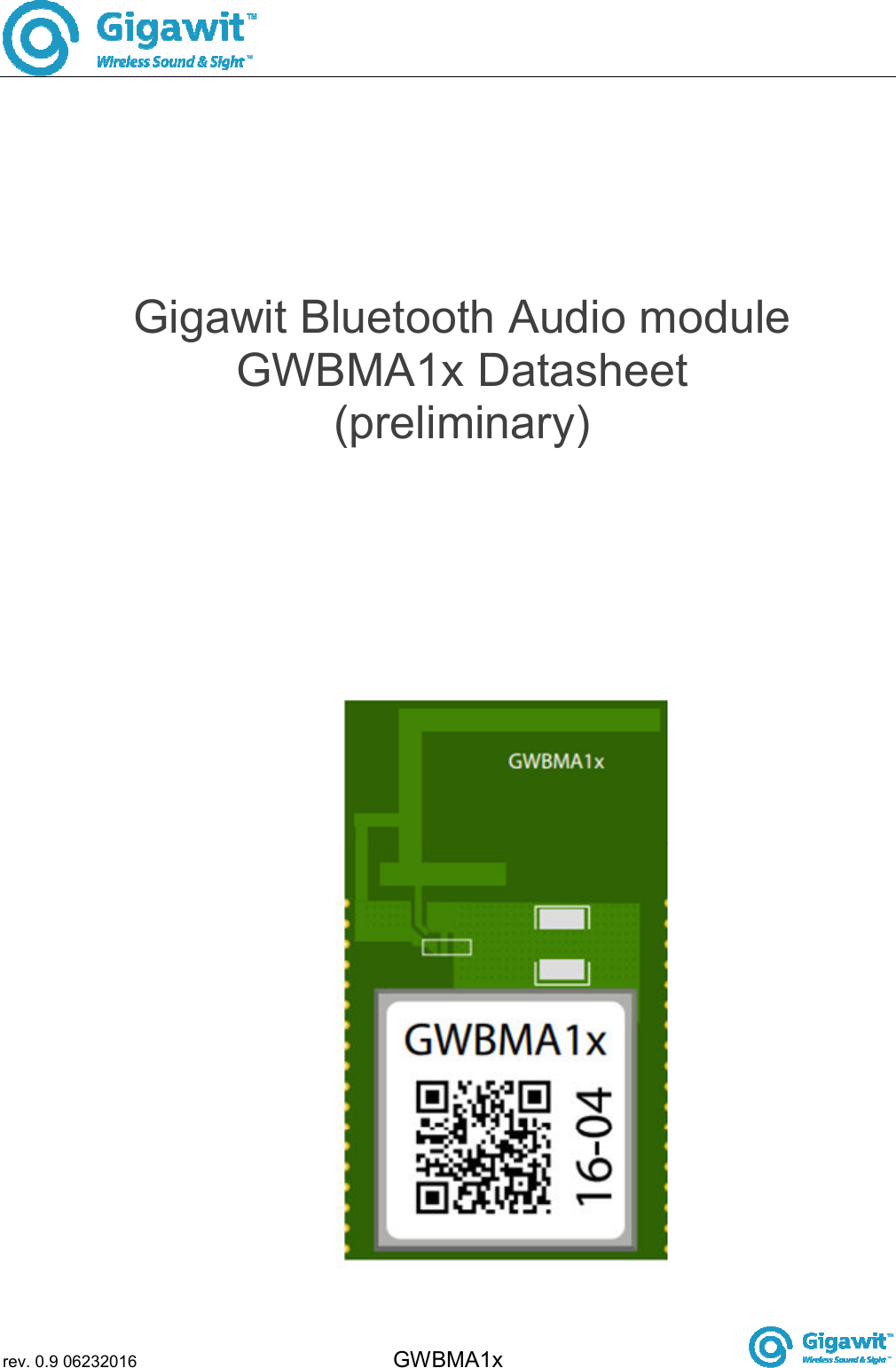
Gigawit Electronics GWBMA1X Bluetooth Wireless Audio Module User Manual GWBMA1xdatasheetrev0 9
Gigawit Electronics Limited Bluetooth Wireless Audio Module GWBMA1xdatasheetrev0 9
UserManual.wiki
>
Gigawit Electronics
>
GWBMA1X User Manual
user manual
Navigation menu
Upload a User Manual
Namespaces
Wiki Guide
HTML
PDF
Info
Views
User Manual
Discussion / Help
Navigation
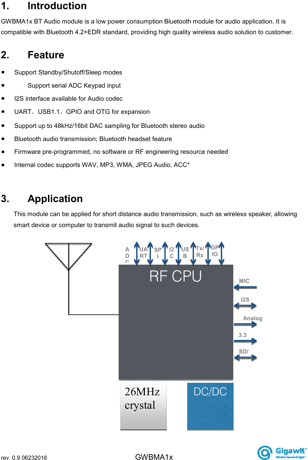
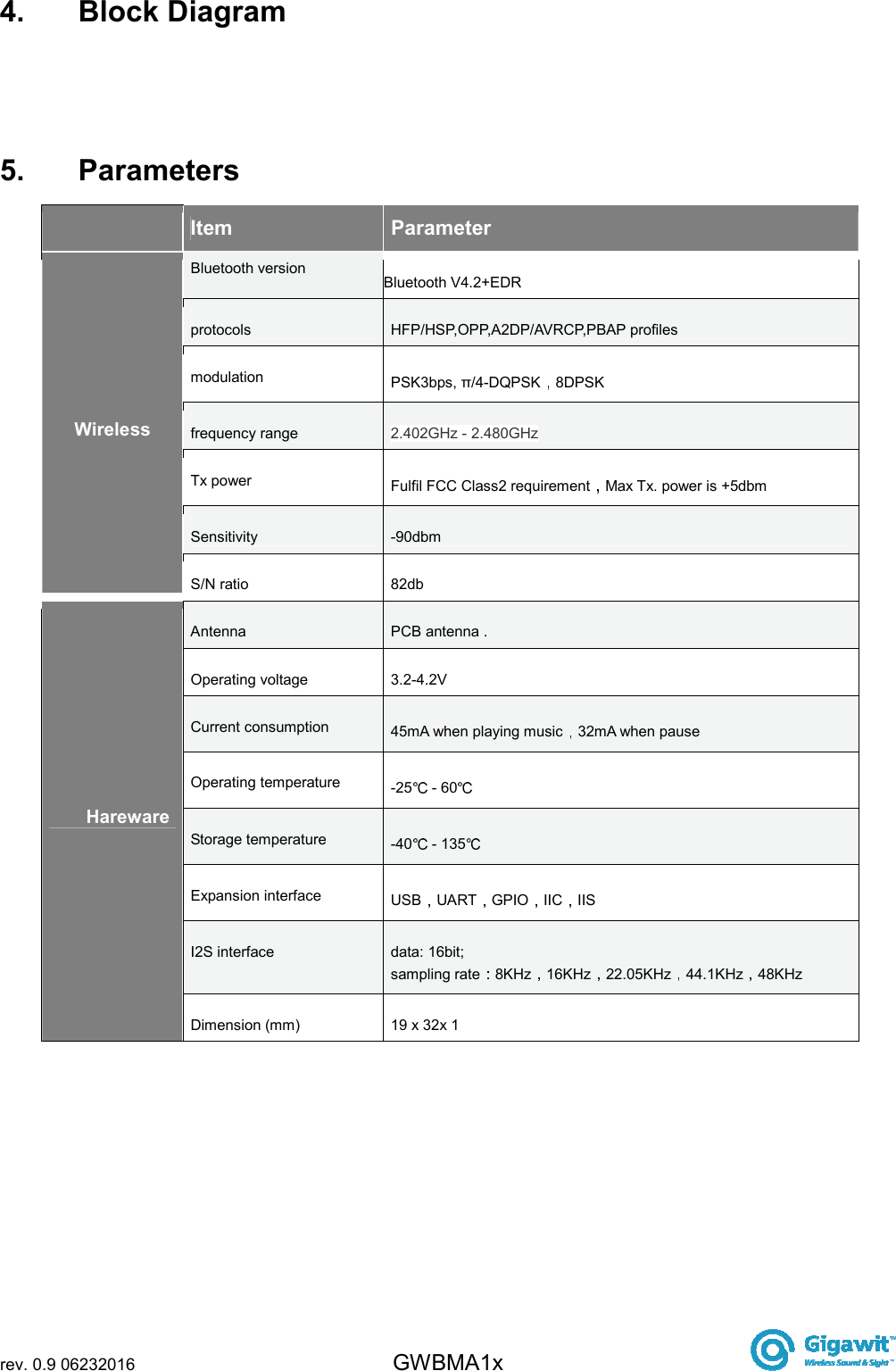
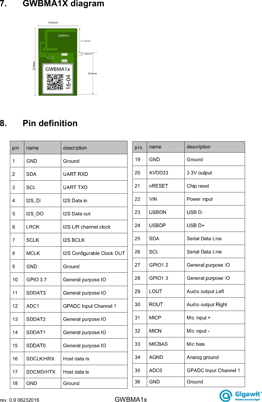
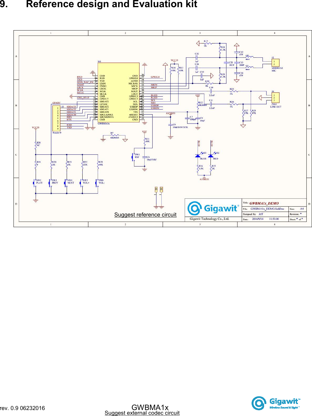
![rev. 0.9 06232016 GWBMA1x 12. GWBMA1X dimension Figure [11]: GWBMA1X dimension](https://usermanual.wiki/Gigawit-Electronics/GWBMA1X/User-Guide-3196016-Page-11.png)