Gigawit Electronics GWBMA1X Bluetooth Wireless Audio Module User Manual GWBMA1xdatasheetrev0 9
Gigawit Electronics Limited Bluetooth Wireless Audio Module GWBMA1xdatasheetrev0 9
user manual
rev. 0.9 06232016
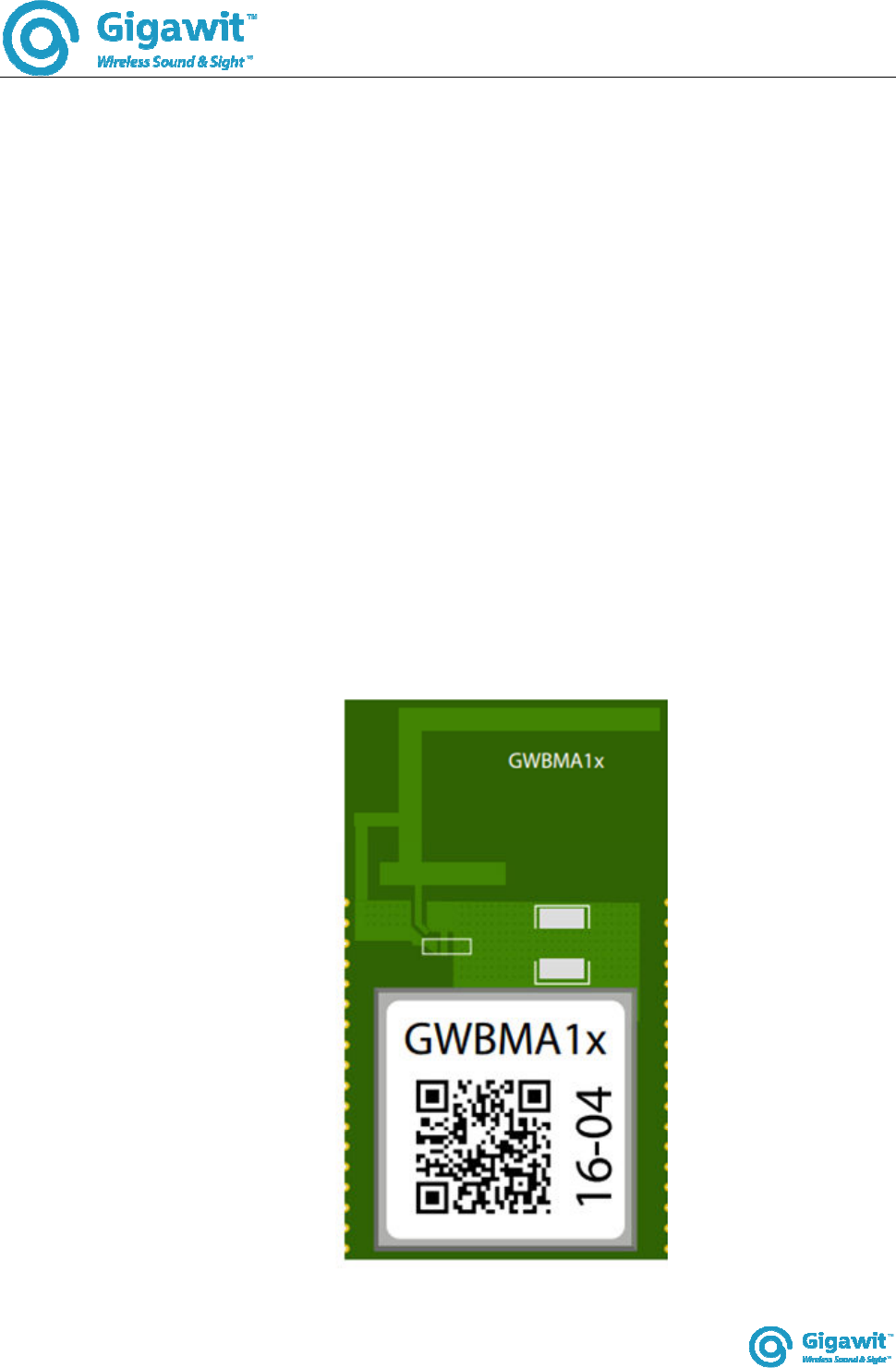
GWBMA1x
Gigawit Bluetooth Audio module
GWBMA1x Datasheet
(preliminary)
rev. 0.9 06232016
GWBMA1x
1. Introduction
GWBMA1x BT Audio module is a low power consumption Bluetooth module for audio application. It is
compatible with Bluetooth 4.2+EDR standard, providing high quality wireless audio solution to customer.
2. Feature
Support Standby/Shutoff/Sleep modes
Support serial ADC Keypad input
I2S interface available for Audio codec
UART USB1.1 GPIO and OTG for expansion
Support up to 48kHz/16bit DAC sampling for Bluetooth stereo audio
Bluetooth audio transmission; Bluetooth headset feature
Firmware pre-programmed, no software or RF engineering resource needed
Internal codec supports WAV, MP3, WMA, JPEG Audio, ACC*
3. Application
This module can be applied for short distance audio transmission, such as wireless speaker, allowing
smart device or computer to transmit audio signal to such devices.
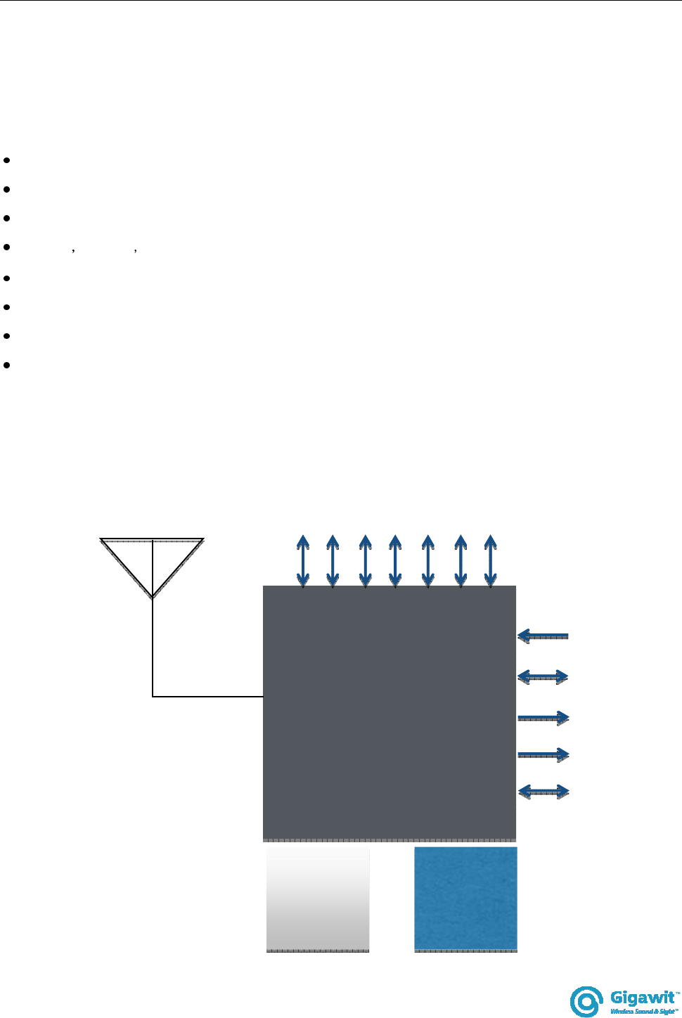
RF CPU
26MHz
crystal
DC/DC
I
An
3
SD
UA
RT
A
D
C
SP
I
I2
C
US
B
Tx/
Rx
GP
IO
MIC
I2S
Analog
output
3.3
V
SD/
TF
rev. 0.9 06232016
GWBMA1x
4. Block Diagram
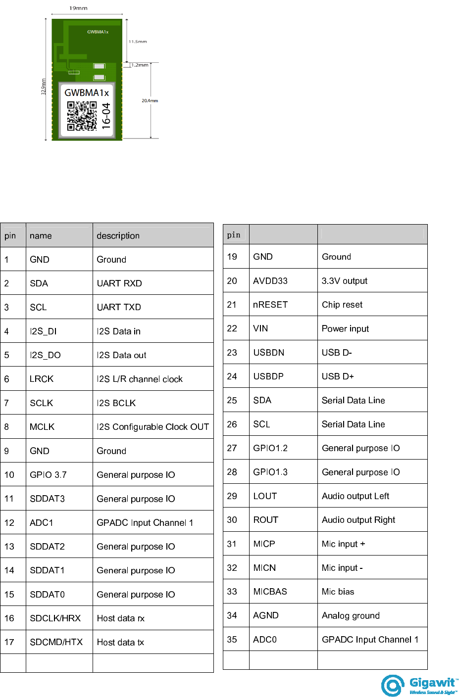
5. Parameters
Item
Parameter
Bluetooth version
Bluetooth V4.2+EDR
protocols
HFP/HSP,OPP,A2DP/AVRCP,PBAP profiles
modulation
PSK3bps, π/4-DQPSK 8DPSK
frequency range
2.402GHz - 2.480GHz
Tx power
Fulfil FCC Class2 requirement Max Tx. power is +5dbm
Sensitivity
-90dbm
Wireless
S/N ratio
82db
Antenna
Operating voltage
3.2-4.2V
Current consumption
45mA when playing music 32mA when pause
Operating temperature
-25 - 60
Storage temperature
-40 - 135
Expansion interface
USB UART GPIO IIC IIS
I2S interface
data: 16bit;
sampling rate 8KHz 16KHz 22.05KHz 44.1KHz 48KHz
Hareware
Dimension (mm)
19 x 32x 1
PCB antenna .

rev. 0.9 06232016
GWBMA1x
6. Firmware
GWBMA1x comes with standard firmware with either analog output (Pin 29 -30) or digital output (IIS).
The firmware already embedded all the basic features, such as Bluetooth Audio, key input, LED
control..etc. Customer needs no engineering resource on those basic features.
Internal codec firmware
GWBMA1X embedded with internal codec, which output analog signal directly. Customer can simply
connect GWBMA1x analog output to earphone for audio play back, or to an audio amplifier.
External codec firmware
With this firmware, GWBMA1x will by-pass its internal codec and directly output the digital audio
signal received from wireless side to I2S output, which is connected to an external codec. Customer
can select different codec in order to satisfies different sound quality requirements. Beside the codec
feature, any other feature of this firmware will be same as the Internal code firmware.
Customised firmware
GWBMA1X is a high performance and flexibility Bluetooth audio module, and there are many rooms
for embedded features. It is possible to provide a customised firmware base on customer’s
requirement base on the module hardware. Customer may contact us through our local partners for
such customisation service. NRE will be needed for customisation service.
Firmware loading
Firmware can be loaded into GWBMA1X module through pin 16 and 17 by a JTAG adaptor. A window
base application will be provided for loading a GWBMA1X firmware from computer to the module.
rev. 0.9 06232016
GWBMA1x
7. GWBMA1X diagram
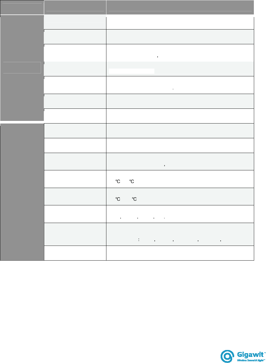
8. Pin definition
18 GND Ground
name
description
36
GND
Ground
rev. 0.9 06232016
GWBMA1x
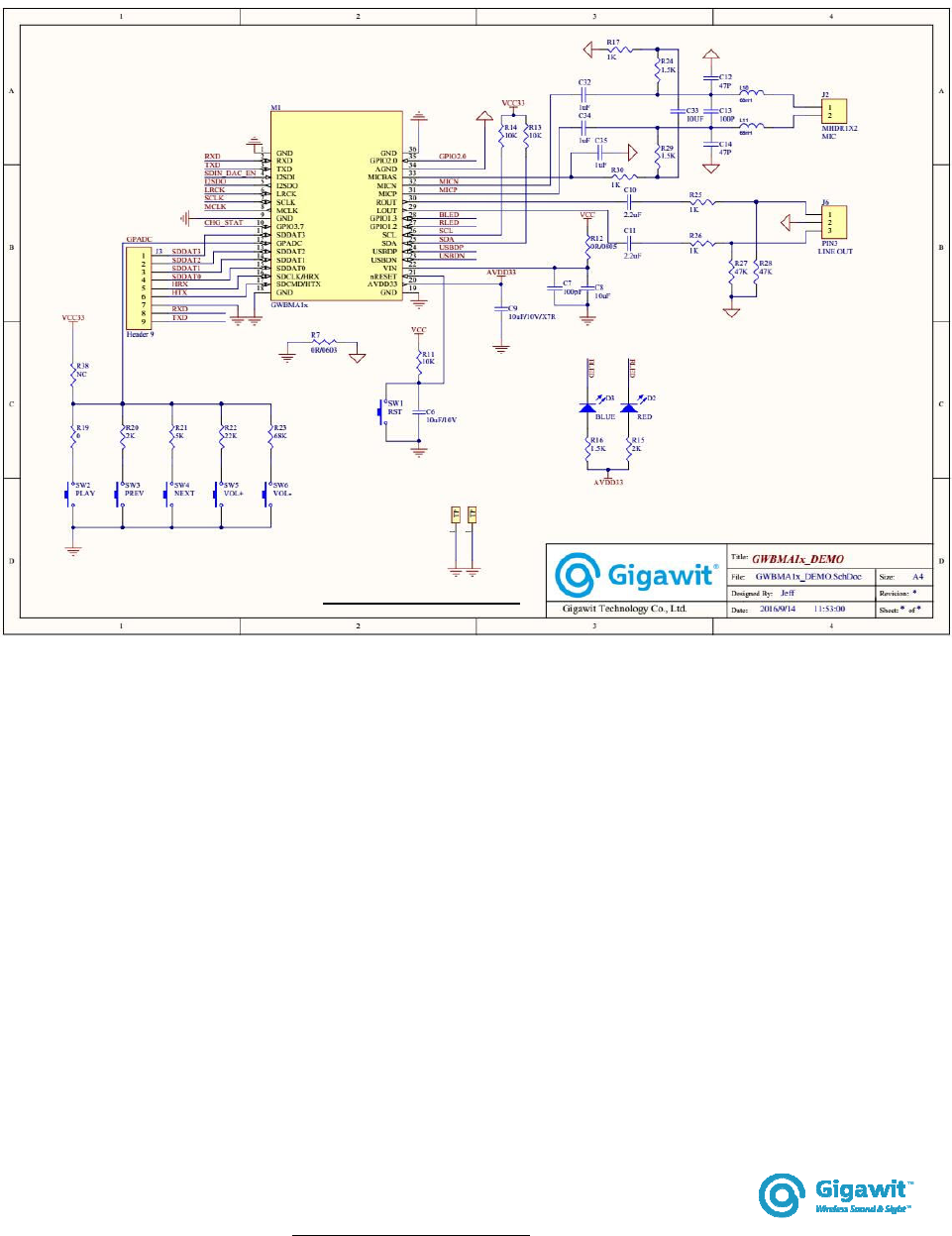
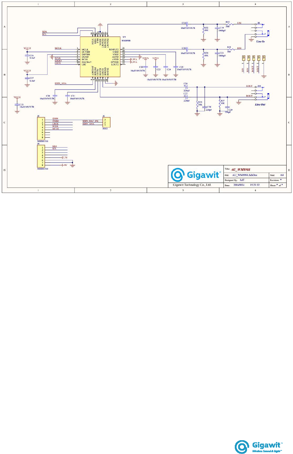
9. Reference design and Evaluation kit
Suggest external codec circuit
Suggest reference circuit
rev. 0.9 06232016
GWBMA1x
rev. 0.9 06232016
GWBMA1x
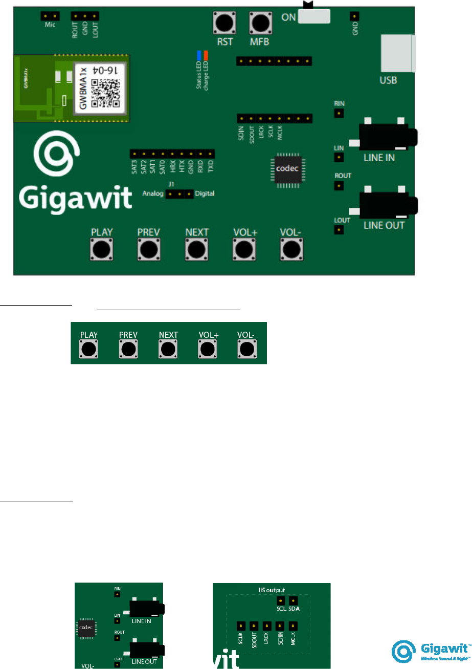
10. Evaluation board
GWBMA1X evaluation board provides a complete circuit GWBMA1X where customer
can evaluate each feature of the standard firmware, or any customised firmware.
Push buttons
Except the RST button (system reset), 5 push buttons for controlling the music
Play : Play, pause music and answer call
Prev : Jump to previous song
Next : Jump to next song
Vol+, Vol- : Volume increment/decrement
Codec output
When external codec firmware loaded, the external codec on the EVK will be activated.
The on board codec will then convert digital data from the module to LINE OUT and
convert audio signal from LINE IN to the module.
User can also connect the I2S related signal pin to his own codec circuit.
GWBMA1X evaluation board

rev. 0.9 06232016
GWBMA1x
When internal codec firmware is loaded, the module will decode the signal internally
and output audio signal on the board; on the other hand, audio from MIC will also be
coded in the module.
Battery charger
A Li-ion charger is also on board, customer can simply solder a 3.7V Li-ion battery to
the board. The RED LED will turn on when charging.
USB connector
It is used as power supply of the board, and battery charging as well (if Li-ion battery
connected). Data pin is also connect to GWBMA1X USB port, but is not yet enabled
until future or customised firmware.
rev. 0.9 06232016
GWBMA1x
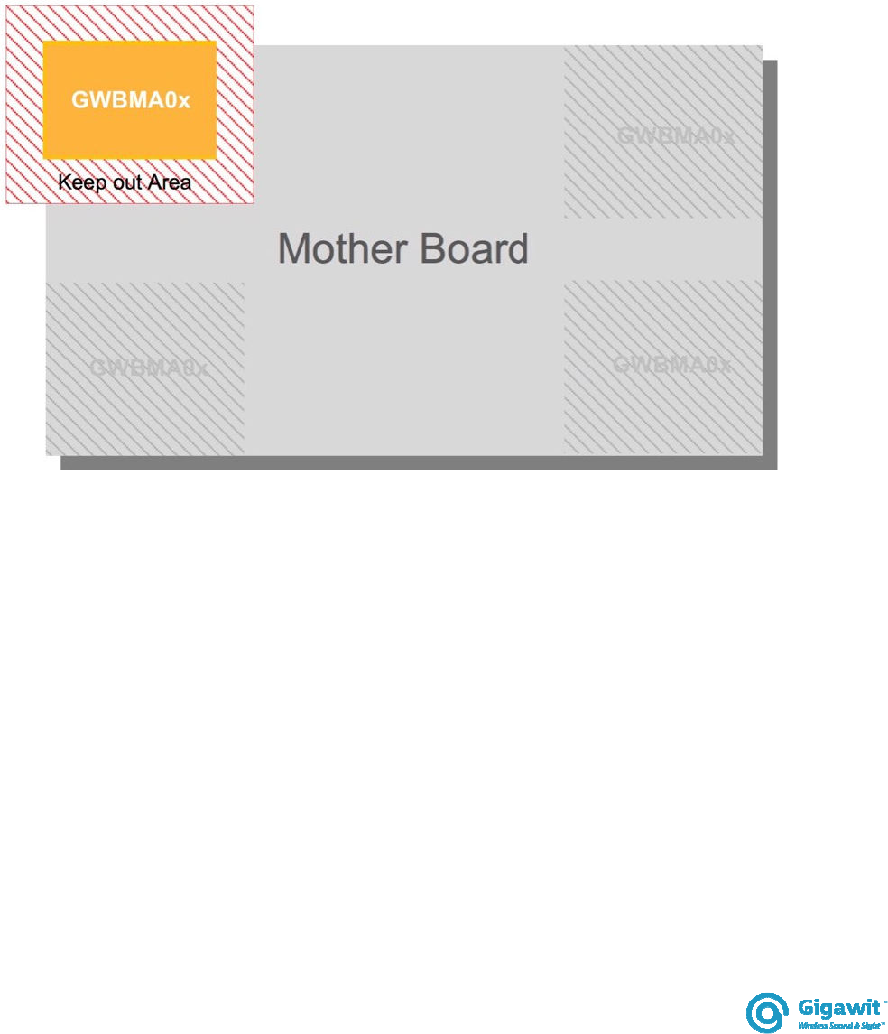
11. Layout requirement
GWBMA1X is a sensitive RF device, and it is suggestion to be put on
In order to obtain the best performance, GWBMA1X should be placed on corner of PCB, and keep
certain distance from other components, especially metal components, such are speaker, transformer,
battery, heat sink and metal plate.
The diagram shows the layout for GWBMA1X module. Inappropriate installation may deteriorate the RF
performance.
GWAPA0x layout recommendation
rev. 0.9 06232016
GWBMA1x
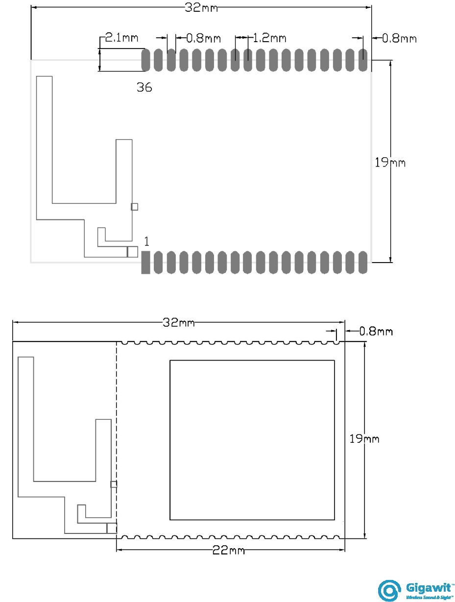
12. GWBMA1X dimension
Figure [11]: GWBMA1X dimension

rev. 0.9 06232016
GWBMA1x
13. Naming
GW BMA 0x
Variants Bluetooth Audio Gigawit
prefix

rev. 0.9 06232016
GWBMA1x
14. Contact information
Head quarter:
Room 308, Building 25, Keyuan West Industrial Area, Nanshan District,
Shenzhen City, Guangdong Province, China
Tel: +86-755-86329300
Fax: +86-755-86329882
E-mail: info@gigawit.com
Sales and marketing office:
Tel: +852-91983405
Fax: +852 3013 8763
E-mail: sales@k-sol.com.hk
Integrator is reminded to assure that these installation instructions
will not be made available to the end
-
user of the final host device.
The final host device, into which this RF Module isintegrated" hasto be labelled
with an auxilliary lable stating the FCC IDofthe RF Module,
such as "Contains FCC ID: QECGWBMA1X"
"This device complies with part 15 of the FCC rules. Operation is subject to the following two
conditions:
(1)this devicemay not cause harmful interference, and
(2)this devicemust accept any interference received, including
interference thatmay cause undesired operation."
NOTE: This equipment has been tested and found to comply with the limits for a Class B digital
device, pursuant to part 15 of the FCC Rules. These limits are designed to provide reasonable
protection
against harmful interference in a residential installation. This equipment generates, uses and can
radiate radio frequency energy and, if not installed and used in accordance with the instructions,
may cause harmful interference to radio communications. However, there is no guarantee that
interference will not occur in a particular installation. If this equipment does cause harmful
interference to radio or television reception, which can be determined by turning the equipment
off and on, the user is encouraged to try to correct the interference by one or more of the
following measures:
--Reorient or relocate the receiving antenna.
--Increase the separation between the equipment and receiver.
--Connect the equipment into an outlet on a circuit different from that to which the receiver is
connected.
--Consult the dealer or an experienced radio/TV technician for help.
Changes or modifications to this unit not expressly approved by the party responsible for
compliance could void the user's authority to operate the equipment.
(OEM) Integrator has to assure compliance of the entire end-product incl. the integrated RF Module.
For 15 B (§15.107 and if applicable §15.107) compliance, the host manufacturer is required to
show compliance with 15 while the module is installed and operating.
Furthermore the module should be transmitting and the evaluation should confirm that the module's
intentional emissions (15C) are compliant (fundamental / out-of-band). Finally the integrator has
to apply the appropriate equipment authorization (e.g. Verification) for the new host device per
definition in §15.101.