Manual

Preliminary
05/16/02
MDE-4017B Mat Reader Assembly Kit C00016-XXX Installation Manual • May 2002 Page 1
Introduction
Purpose of this Manual
This manual provides instruction for installing Mat Reader Assembly Kit C00016-XXX.
The Mat Reader allows customers to automatically authorize sales using a hand-held
transponder tag.
Important Notice
This equipment has been tested and found to comply with the limits for a Class A digital
device pursuant to Part 15 of the Federal Communications Commission (FCC) Rules. These
limits are designed to provide reasonable protection against harmful interference when the
equipment is operated in a commercial environment. This equipment generates, uses and can
radiate radio frequency energy, and if not installed and used in accordance with the instruction
manual, may cause harmful interference to radio communications. Operation of this
equipment in a residential area is likely to cause harmful interference in which case the user
will be required to correct the interference at his own expense. Changes or modifications not
expressly approved by the manufacturer could void the user’s authority to operate this
equipment.
The long term characteristics or the possible physiological effects of radio frequency
electromagnetic fields have not been investigated by Underwriters’ Laboratories, Inc. (UL®).
Required Reading
Before installing the equipment, the installer must read, understand, and follow:
•this manual
•NFPA 70, The National Electrical Code (orderable at www.nfpa.org)
•applicable federal, state and local codes and regulations
Failure to do so may adversely effect the safe use and operation of the equipment.
MDE-4017B
Mat Reader Assembly Kit C00016-XXX
Installation Manual
May 2002

Preliminary
05/16/02
Important Safety Information
Page 2 MDE-4017B Mat Reader Assembly Kit C00016-XXX Installation Manual • May 2002
Important Safety Information
This section introduces the hazards and safety precautions associated with installing,
inspecting, maintaining or servicing this product. Before performing any task on this product,
read this safety information and the applicable sections in this manual, where additional
hazards and safety precautions for your task will be found. Electrical shock could occur and
cause death or serious injury if these safe service procedures are not followed.
Preliminary Precautions
Read, understand and follow this manual and any other labels or related materials supplied
with this equipment.
Follow the Regulations
There is applicable information in: NFPA 70: National Electrical Code (NEC); OSHA
regulations; and federal, state, and local codes which must be followed. Failure to install,
maintain or service this equipment in accordance with these codes, regulations and standards
may lead to legal citations with penalties or affect the safe use and operation of the equipment.
Preliminary
05/16/02
Page 3 MDE-4017B Mat Reader Assembly Kit C00016-XXX Installation Manual • May 2002
Important Safety Information
Safety Symbols and Warning Words
Alert Symbol
This safety alert symbol is used in this manual and on warning labels to alert you to a
precaution which must be followed to prevent potential personal safety hazards. Obey safety
directives that follow this symbol to avoid possible injury or death.
Signal Words
These signal words used in this manual and on warning labels tell you the seriousness of
particular safety hazards. The precautions that follow must be followed to prevent death,
injury or damage to the equipment.
Proper Grounding is Required
Proper grounding is required for safe operation. See installation manual and applicable NEC,
NFPA and local electrical codes for requirements.
Avoid Pinched Wires
Pinched or cut wires (cables) may damage components. Exposed wires could create sparks and
electrical shorts when applying power.
Other Useful Safety Information
Replacement Parts
Use only genuine Gilbarco replacement parts. Using parts other than genuine Gilbarco
replacement parts could create a safety hazard, violate national, state and local regulations or
void warranty.
This signal word designates a hazard or unsafe practice which may result in minor injury.
This signal word is used to alert you to a hazard or unsafe practice which will result in
death or serious injury.
This alerts you to a hazard or unsafe practice that could result in death or serious injury.
CAUTION
When used by itself, CAUTION designates a hazard or unsafe practice which may result in
property or equipment damage.
CAUTION
DANGER
WARNING

Preliminary
05/16/02
Reference Information
Page 4 MDE-4017B Mat Reader Assembly Kit C00016-XXX Installation Manual • May 2002
Reference Information
Related Documents
Installer must obtain, read and understand all site preparation documentation provided by the
point of sale company authorizing the installation before attempting to install this equipment.
In addition, the installer must be familiar with the information in the following documents:
Required Tools
The following equipment is needed to install all Mat Reader kits:
•drill motor and bits
•needle nose pliers
•screwdriver, Phillips® head
•Zircon® stud/bracket finder
Coaxial Cable and SMA Connector Handling Requirements
Coaxial antenna cables are more flexible and have a smaller diameter than more familiar
coaxial cable, such as that used for cable television. However, all coaxial cables share this
characteristic: turns or bends in coaxial cables must be gradual loops, no sharper than a 1-inch
radius or 2-inch diameter (2.54 centimeter radius or 5 centimeter diameter).
An SMA connector is a type of connector that uses a threaded mount and connects one optical
fiber. Due to its small size, use care when connecting the coaxial cable to as to not damage the
SMA connector on the Interface Box or the coaxial cable.
Document
Number Title GOLDSM Library
MDE-3110 PC-Based G-SITE® System Installation Manual G-SITE
MDE-3111 PC-Based G-SITE System Start-Up and Service Manual • G-SITE
•Service Manual
MDE-3620 Gilbarco® POS Console Site Preparation Manual Site Prep
MDE-3982 Advanced Console Application KS000-XXXPC G-SITE
Too severe a turn or bend in the cable will break the center (solid) fiber. This can
result in an intermittent signal. It may also result in what appears to be proper
performance at installation that is followed by premature failure and field service.
In addition, a damaged cable will cause a situation where the transmitter printed
circuit board (PCB) is powered without load, and damage the PCB.
CAUTION

Preliminary
05/16/02
Page 5 MDE-4017B Mat Reader Assembly Kit C00016-XXX Installation Manual • May 2002
Parts Lists
Parts Lists
C00016-006 Kit - Low Frequency
C00016-006 Kits contain the following parts:
C00016-008 Kit - High Frequency
C00016-008 Kits contain the following parts:
Description Part Number Quantity
box, interface assembly M01814A001 1
tape, neoprene foam M01870B001 2
channel, plastic filler M01871B001 1
cable, mat reader drive M01872A001 1
ferrite half Q11433-110 2
ferrite, snap-on Q11433-107 1
tape, acrylic foam K85492-72 1
power supply M01878B001 1
jack, jump Q11011-01 1
cable, data, CAT-5 Q13482-06 1
clamp, cable, stick on, small Q13459-01 3
decal, UL/FCC M01868A001 1
document, installation MDE-4017 1
screw, thread forming, 8-32x3/8”K85736-06 2
Description Part Number Quantity
box, interface assembly M01814A002 1
tape, neoprene foam M01870B002 1
channel, plastic filler M01871B002 1
cable, mat reader drive M01872A001 1
transient suppressor, magnetically coupled Q11433-110 2
ferrite, snap-on Q11433-106 1
ferrite, snap-on Q11433-107 1
tape, acrylic foam K85492-72 1
power supply M01878B001 1
jack, jump Q11011-01 10
cable, data, CAT-5 Q13482-06 1
clamp, cable, stick on, small Q13459-01 3
decal, UL/FCC M01868A002 1
document, installation MDE-4017 1
screw, thread forming, 8-32x3/8”K85736-06 2

Preliminary
05/16/02
Parts Lists
Page 6 MDE-4017B Mat Reader Assembly Kit C00016-XXX Installation Manual • May 2002
C00016-010 Kit - Low Frequency Mini Mat
C00016-010 Kits contain the following parts:
Mat Reader
The following component is also required in addition to the C00016-XXX kit.
Description Part Number Quantity
box, interface assembly M01814A001 1
tape, neoprene foam M02498B001 1
cable, mat reader drive M01872A002 1
ferrite, snap-on Q11433-107 1
power supply M01878B001 1
jack, jump Q11011-01 1
cable, data, CAT-5 Q13482-06 1
clamp, cable, stick on, small Q13459-01 3
decal, UL/FCC/IC® (Industry Canada),
see Note
M01868A003 1
document, installation MDE-4017 1
screw, thread forming, 8-32x3/8”K85736-06 2
Note: “IC:” before the certification/registration number only signifies that the Industry
Canada technical specifications were met.
Description Part Number (Note) Applicable Kit(s) Quantity
mat reader, small MR01002GXXX C00016-006
C00016-008
1
mat reader, mini MR01003GXXX C00016-010 1
Note: XXX is the graphic-specific identifier.
Preliminary
05/16/02
Page 7 MDE-4017B Mat Reader Assembly Kit C00016-XXX Installation Manual • May 2002
Interconnect/Block Diagrams
Interconnect/Block Diagrams
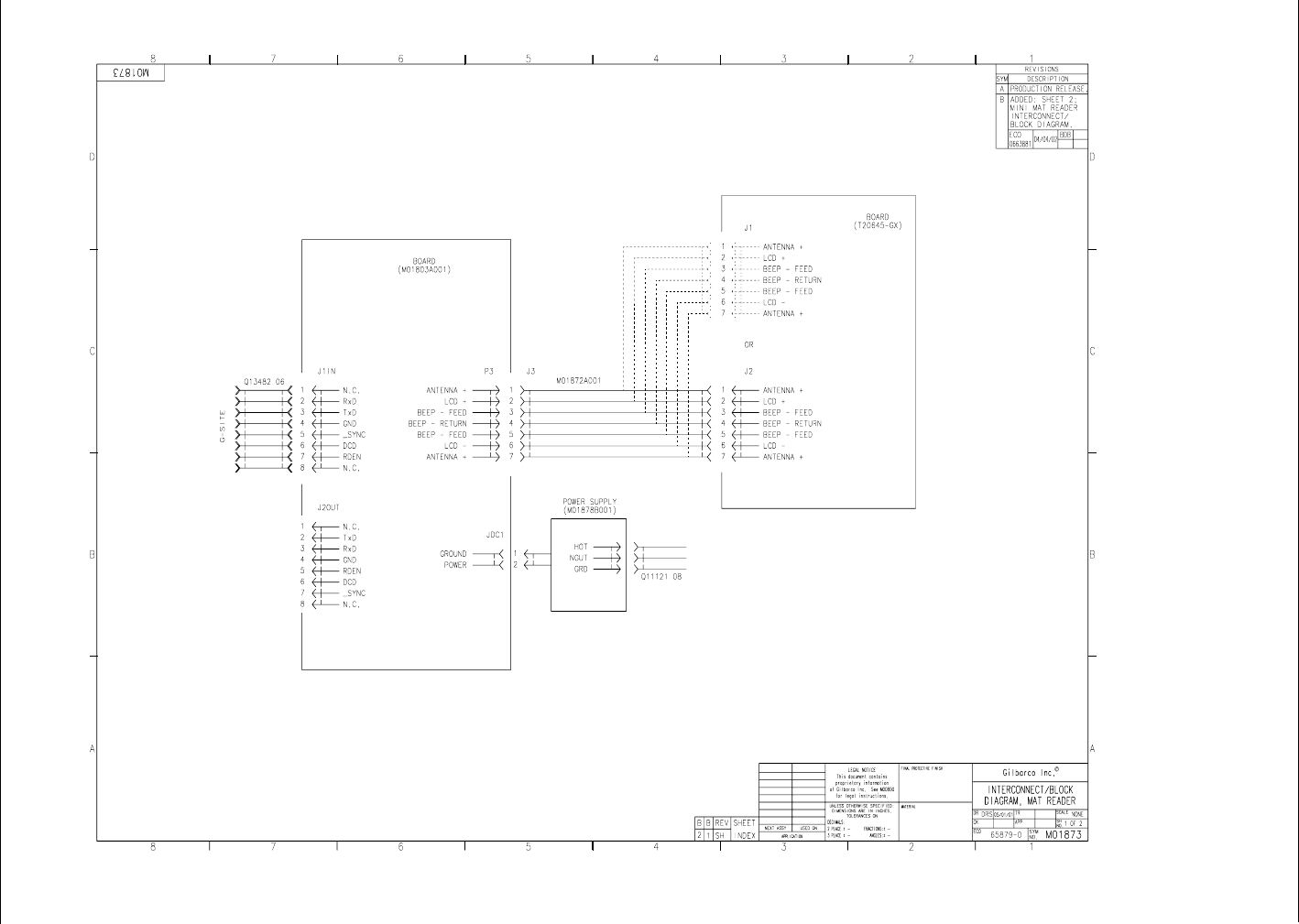
Mat Reader Interconnect/Block Diagram M01873 (Sheet 1)
115VAC
+12VDC
DC
In Mat Reader Assembly
MR01002GXXX
In Interface Box Assembly
M01814A001
Preliminary
05/16/02
Interconnect/Block Diagrams
Page 8 MDE-4017B Mat Reader Assembly Kit C00016-XXX Installation Manual • May 2002
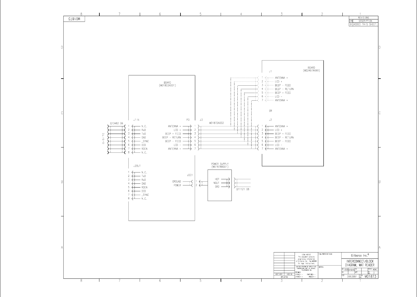
Mat Reader Interconnect/Block Diagram M01873 (Sheet 2)
DC
+12VDC
115VAC
In Mat Reader Assembly
MR01003GXXX
In Interface Box Assembly
M01814A001
Preliminary
05/16/02
Page 9 MDE-4017B Mat Reader Assembly Kit C00016-XXX Installation Manual • May 2002
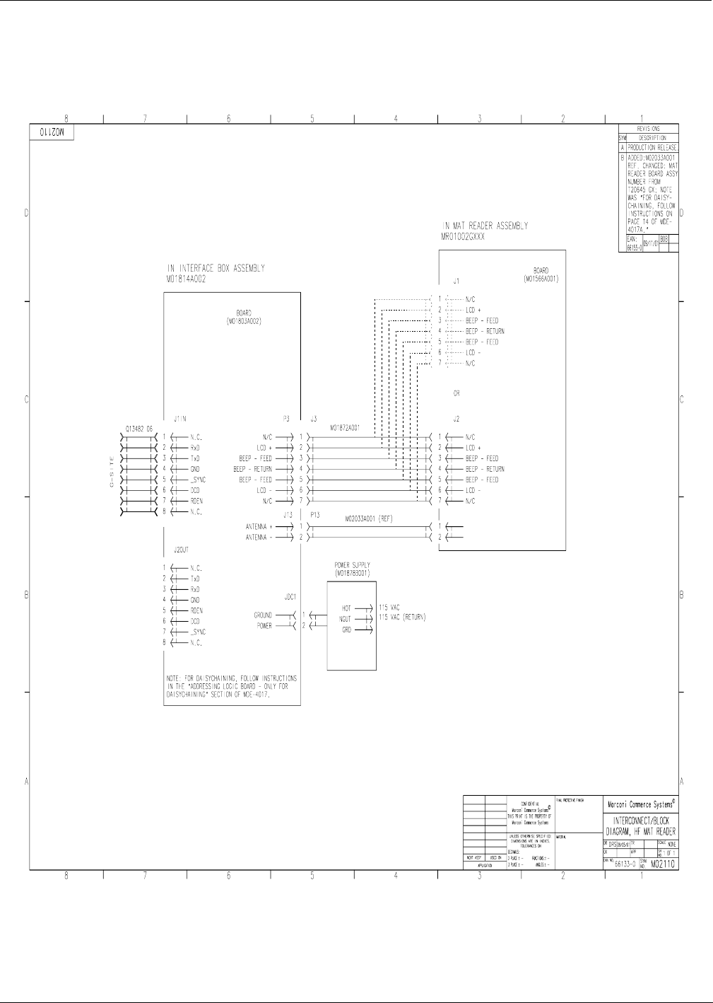
Interconnect/Block Diagrams
Mat Reader Interconnect/Block Diagram M02110

Preliminary
05/16/02
Installation
Page 10 MDE-4017B Mat Reader Assembly Kit C00016-XXX Installation Manual • May 2002
Installation
Note: All installation work is to be accomplished between the hours specified by the point of
sale company authorizing the installation.
Install the Mat Reader assembly according to the following instructions.
Collect and arrange for safety and convenience all tools and equipment.
Positioning the Mat Reader
Gilbarco recommends the following concerning the placement of a Mat Reader on the counter
top relative the following devices:
•any cathode ray tube (CRT), such as the point-of-sale (POS) monitor
•any device with a card reader, such as a personal identification number (PIN) pad
•the Mat Reader Interface Box
•countertop material
In Relation to a CRT
In general, a Mat Reader should be positioned as far away as is conveniently possible from any
CRT device to avoid interference from the CRT and to ensure optimum performance of the
Mat Reader. The interference from a CRT can vary greatly from unit to unit and model to
model. Also, the presence of nearby masses of metal can affect the influence of a CRT.
There is no universal minimum separation that guarantees trouble-free operation. If the
distance between the Mat Reader and CRT cannot be increased, changing the relative
orientation of these items may yield better operation of the Mat Reader. However, increasing
the distance will always give the most dramatic improvement in Mat Reader performance.
In Relation to a Card Reader
In general, any device with a card reader should be positioned as far as is conveniently
possible from a Mat Reader. Since card readers are unshielded, loosely filtered devices, they
are potential victims of any magnetic interference. The Mat Reader generates a magnetic field
as part of its normal operation that can be such a source of magnetic interference to a card
reader.
If a known, good card reader begins to display poor read performance after the addition of a
Mat Reader to the POS system, significant improvements to card reader performance may be
realized by simply increasing its separation from the Mat Reader by as little as a few inches.
As a general rule, placing a card reader beside a Mat Reader has far less effect on the card
reader than actually using the card reader while it is physically on, or held over, the Mat
Reader. A counter top configuration where the card reader could be used in this manner should
be avoided.

Preliminary
05/16/02
Page 11 MDE-4017B Mat Reader Assembly Kit C00016-XXX Installation Manual • May 2002
Installation
In Relation to the Interface Box
For optimum Mat Reader performance, the Interface Box should be positioned as close to the
Mat Reader as is conveniently possible. If necessary, the CAT-5 cable, Q13482-06, may be
swapped out for a longer version in order to properly place the Interface Box and still reach the
POS connection. The dash number, such as -06, indicates 6 feet (1.8 meters) long.
In Relation to the Countertop Material
If the countertop material is stainless steel, Formica® covered steel, or some other metallic
material, less than desired performance will be experienced. In the preferred setup, the
countertop should be Corian®, plastic, wood, or some other non-metallic and/or non-ferrous
material.
Preliminary
05/16/02
Installation
Page 12 MDE-4017B Mat Reader Assembly Kit C00016-XXX Installation Manual • May 2002
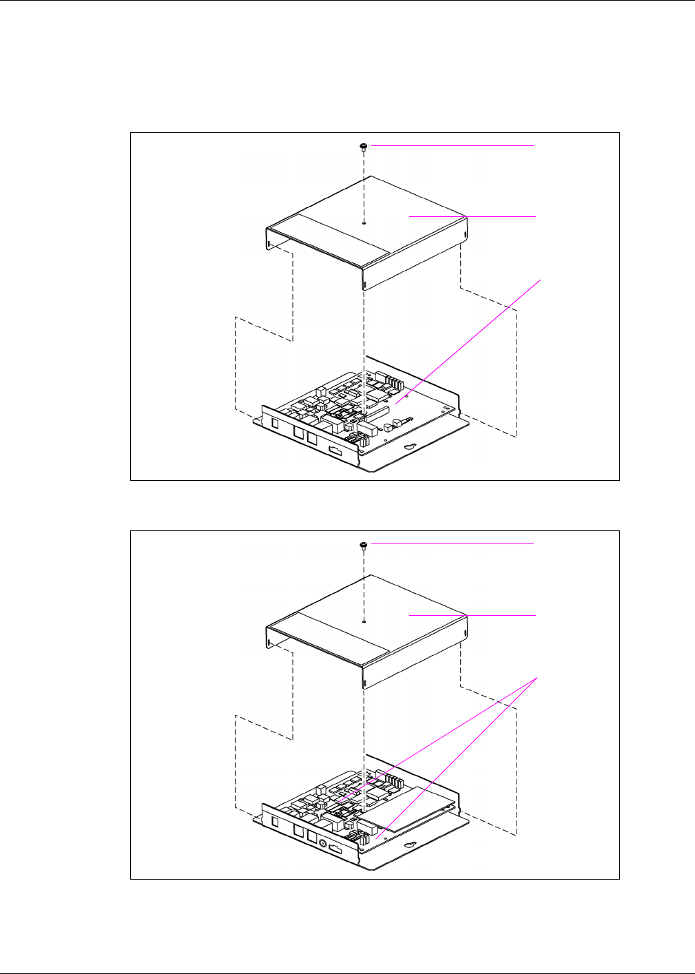
Setting Baud Rate
1Remove Mat Reader Interface Box cover to access the logic board.
Figure: M01814A001 Mat Reader Interface Box Cover
Figure: M01814A002 Mat Reader Interface Box Cover
cover screw
cover
logic board
cover screw
cover
logic board
Preliminary
05/16/02
Page 13 MDE-4017B Mat Reader Assembly Kit C00016-XXX Installation Manual • May 2002
Installation
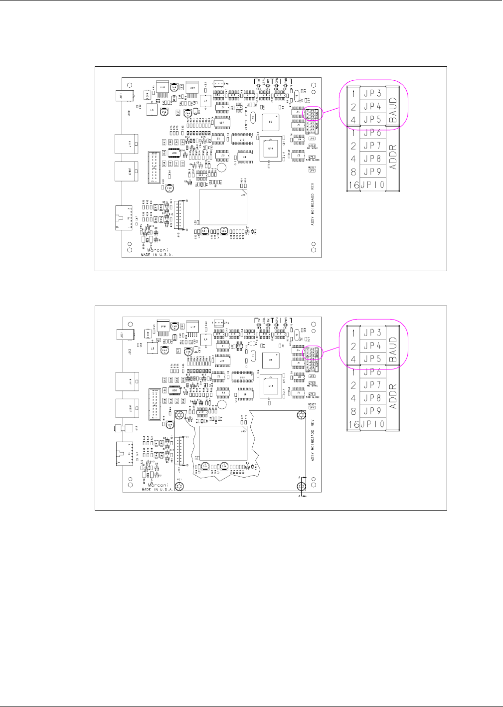
2Locate jump jacks on logic board for Mat Reader.
Figure: Jump Jacks for Baud Rate Setting - M01803A001
Figure: Jump Jacks for Baud Rate Setting - M01803A002

Preliminary
05/16/02
Installation
Page 14 MDE-4017B Mat Reader Assembly Kit C00016-XXX Installation Manual • May 2002
3Set the jump jacks as follows (see the appropriate figure: “Figure: Jump Jacks for Baud Rate
Setting - M01803A001” on page 13 or “Figure: Jump Jacks for Baud Rate Setting -
M01803A002” on page 13).
4If not daisychaining Mat Reader Interface Boxes, reinstall cover.
Note: Daisychaining is connecting the output from one Interface Box to the input of another.
Mat Reader Baud Rates
Baud Rate (Note) BAUD 1 BAUD 2 BAUD 4
4800 OUT OUT OUT
2400 IN OUT OUT
1200 OUT IN OUT
300 IN IN OUT
38400 OUT OUT IN
19200 IN OUT IN
9600 OUT IN IN
4800 IN IN IN
Note: 4800 is the default value and the Mat Reader value.
Electrostatic Discharge Damage
Printed circuit boards (PCBs) and integrated circuits (ICs) are sensitive to electrostatic
discharge caused by static electricity. Electrostatic discharge damages electronic parts.
Follow these guidelines when handling sensitive parts:
•Touch an unpainted metal surface to discharge any static electricity buildup.
•Use a wrist strap connected to a grounded metal frame or chassis.
CAUTION
Preliminary
05/16/02
Page 15 MDE-4017B Mat Reader Assembly Kit C00016-XXX Installation Manual • May 2002
Installation
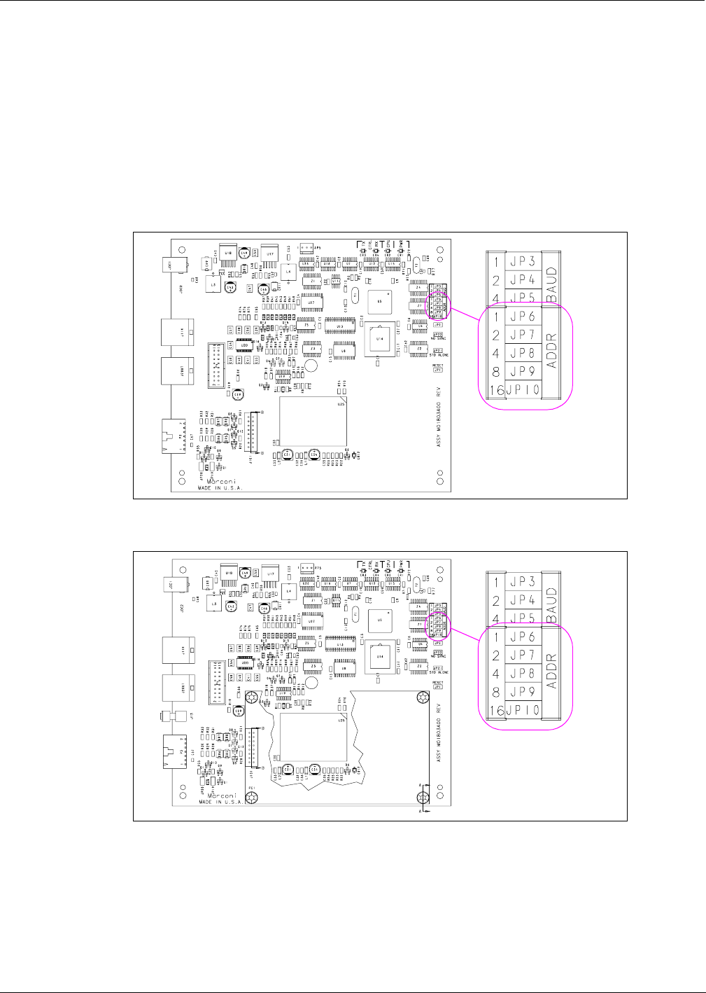
Addressing Logic Board - Only for Daisychaining
Address for Mat Reader must match address on previously installed Mat Reader. Follow these
steps:
1Access logic board for Mat Reader being installed.
2Locate jump jacks on previously installed Mat Reader logic board M01803A001 or
M01803A002 as appropriate.
Figure: M01803A001 Jump Jacks for Address Setting
Figure: M01803A002 Jump Jacks for Address Setting
3Note position of jump jacks on previously installed Mat Reader logic board, and set jump
jacks on board for Mat Reader being installed to match address on logic board (see Caution
that follows).

Preliminary
05/16/02
Installation
Page 16 MDE-4017B Mat Reader Assembly Kit C00016-XXX Installation Manual • May 2002
4Reinstall cover.
Mat Reader Addresses
Address on Logic Board
M01803A001/M01803A002 ADDR 1 ADDR 2 ADDR 4 ADDR 8 ADDR 16
0 OUT OUT OUT OUT OUT
1 IN OUT OUT OUT OUT
2 OUT IN OUT OUT OUT
3 ININOUTOUTOUT
4 OUT OUT IN OUT OUT
5 IN OUT IN OUT OUT
6 OUT IN IN OUT OUT
7 INININOUTOUT
8 OUT OUT OUT IN OUT
9 IN OUT OUT IN OUT
10 OUT IN OUT IN OUT
11 IN IN OUT IN OUT
12 OUT OUT IN IN OUT
13 IN OUT IN IN OUT
14 OUTINININOUT
15 IN IN IN IN OUT
16 OUT OUT OUT OUT IN
17 IN OUT OUT OUT IN
18 OUT IN OUT OUT IN
19 IN IN OUT OUT IN
20 OUT OUT IN OUT IN
21 IN OUT IN OUT IN
22 OUTININOUTIN
23 IN IN IN OUT IN
24 OUT OUT OUT IN IN
25 IN OUT OUT IN IN
26 OUT IN OUT IN IN
27 IN IN OUT IN IN
28 OUT OUT IN IN IN
29 IN OUT IN IN IN
30 OUTININININ
31 IN IN IN IN IN
Electrostatic Discharge Damage
Printed circuit boards (PCBs) and integrated circuits (ICs) are sensitive to electrostatic
discharge caused by static electricity. Electrostatic discharge damages electronic parts.
Follow these guidelines when handling sensitive parts:
•Touch an unpainted metal surface to discharge any static electricity buildup.
•Use a wrist strap connected to a grounded metal frame or chassis.
CAUTION
Preliminary
05/16/02
Page 17 MDE-4017B Mat Reader Assembly Kit C00016-XXX Installation Manual • May 2002
Installation
Mounting Mat Reader Interface Box
1Determine the location for the installation of indoor equipment. The Interface Box may be
mounted under the counter top (upside down) or vertically on one of the supporting walls of
the counter top.
Note: Refer to site prep document provided by point of sale company and keep in mind overall
5-foot (1.5 meter) length of cable to connect Mat Reader Interface Box to Mat Reader.
Also refer to “In Relation to the Interface Box” on page 11.
2Use a Zircon stud/bracket finder to ensure no electrical conduits or pipes are located inside of
wall where the Mat Reader Interface Box is to be mounted. Also, ensure the Mat Reader
Interface Box is to be located where studs or wall (concrete/brick/drywall) mollys can be used
for mounting.
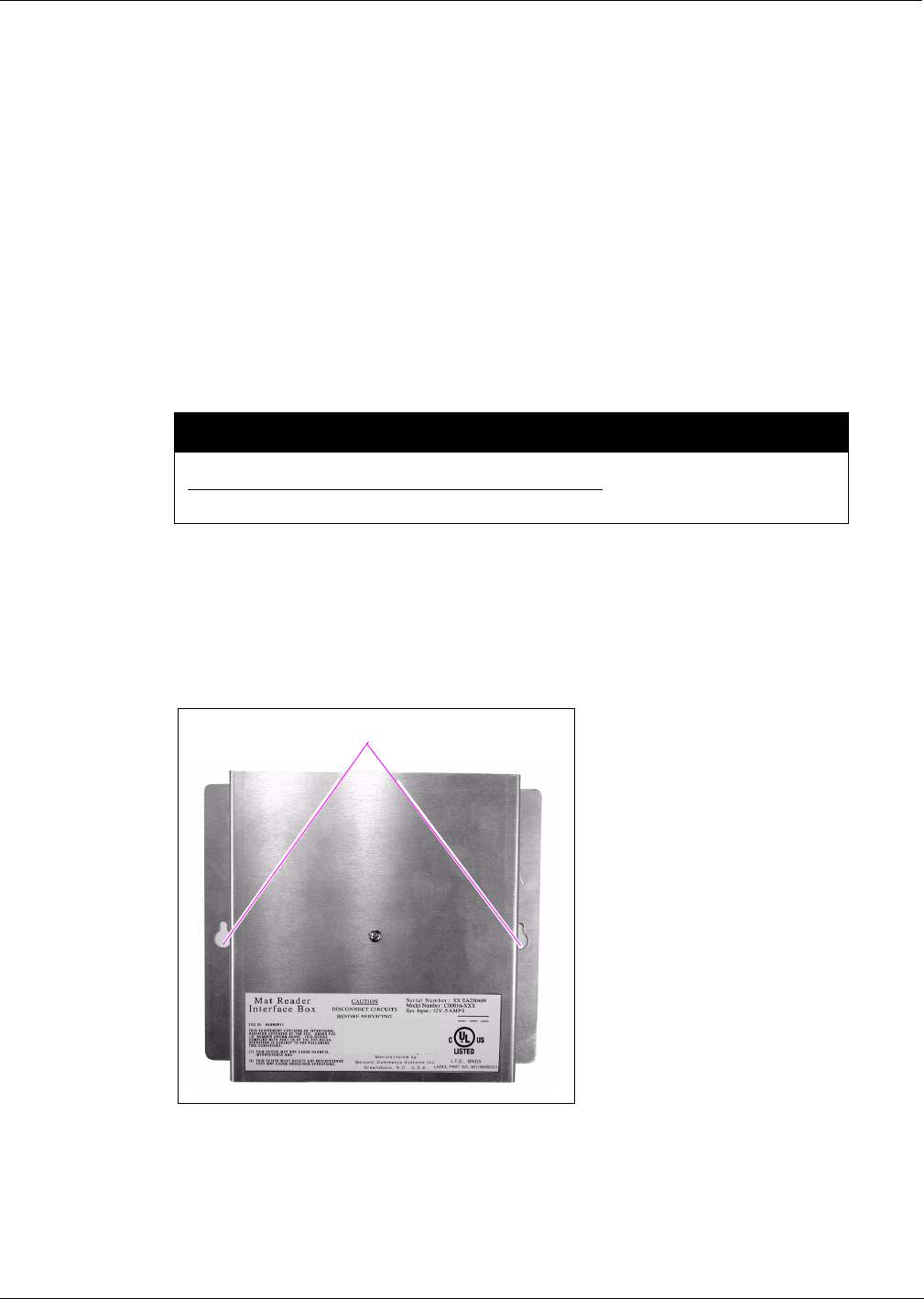
3Mark and drill holes. Insert wall mollys if required.
4Use 8-32 thread-forming screws provided or other appropriate contractor-supplied mounting
hardware to secure the Mat Reader Interface Box to the wall or under counter top.
Note: 3/8-inch deep pilot holes (approximately 1/8-inch diameter) will be required if the
screws provided are used.
Figure: Mat Reader Interface Box Mounting Holes
Do not use the Mat Reader Interface Box as a drill guide. It may be used as a template to
mark the holes to be drilled.
CAUTION
mounting holes
Preliminary
05/16/02
Installation
Page 18 MDE-4017B Mat Reader Assembly Kit C00016-XXX Installation Manual • May 2002
Connecting Data Cables to Mat Reader Interface Box
Run both power and data cables to port end of Mat Reader Interface Box (see “Figure: Mat
Reader Interface Box Mounting Holes” on page 17) as follows:
1Connect the P3 end of the ribbon cable (M01872A001) to the interface port (P3).
2Connect the J1 end of the CAT-5 cable (Q13482-06) to the J1IN port.
Note: The other end of the CAT-5 cable will be connected to the POS controller in the
instructions for “Connecting Data Cables from the Mat Reader Interface Box” on
page 19.
3If daisychaining Interface Boxes, connect a CAT-5 cable from the J1IN port on the other
Interface Box to the J2OUT port on this Interface Box.
4If the Interface Box has an antenna connection, connect one end of the coaxial cable to the
antenna connection (“Figure: Connecting to Mat Reader Interface Box M01803A002” on
page 18). See “Coaxial Cable and SMA Connector Handling Requirements” on page 4.
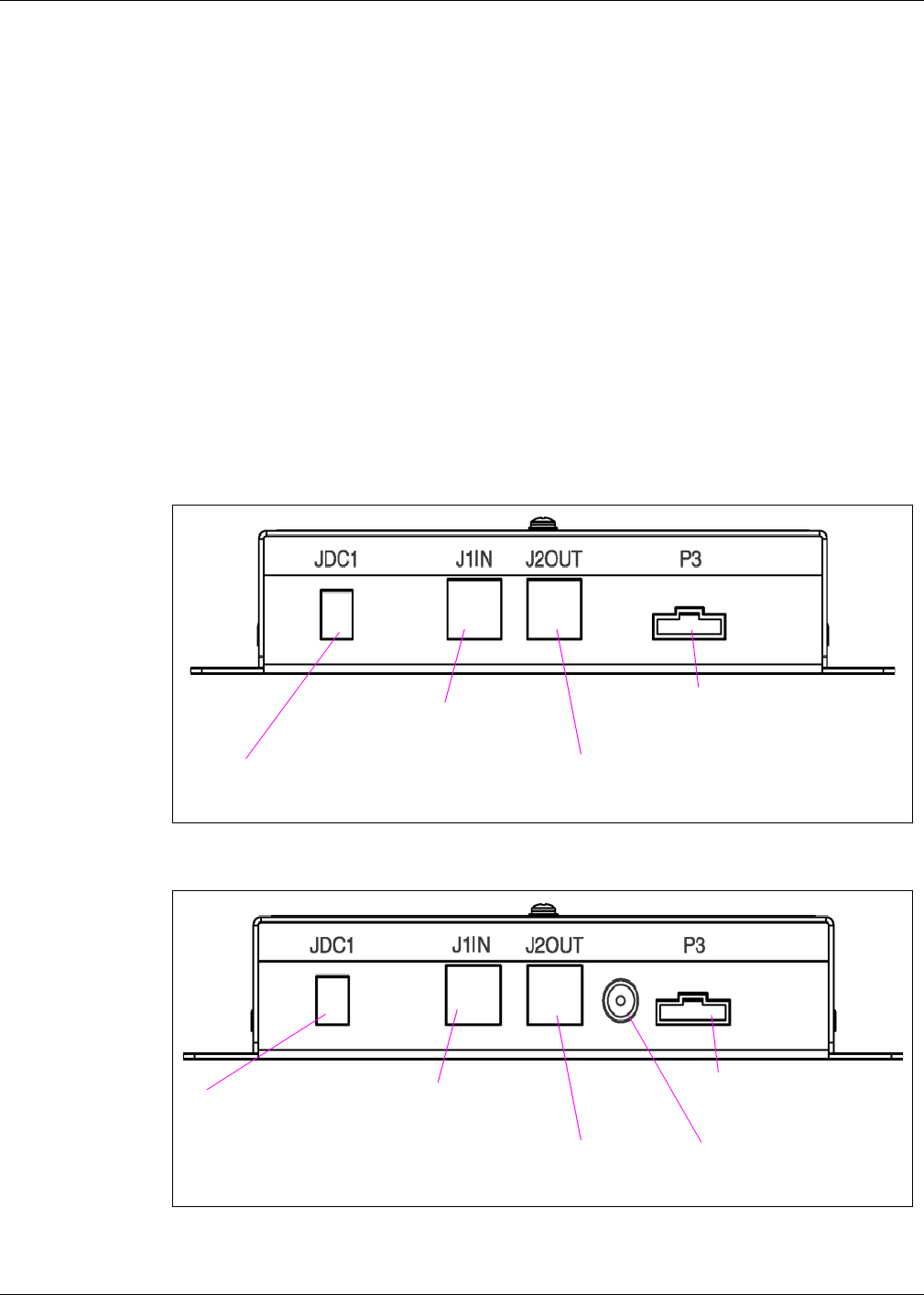
Figure: Connecting to Mat Reader Interface Box M01803A001
Figure: Connecting to Mat Reader Interface Box M01803A002
Connect power supply here.
Connect J1 end of
CAT-5 cable here.
If daisychaining, connect
CAT-5 from J1IN on other
interface box here.
Connect P3 end of
mat reader cable
here.
Connect power supply here. Connect J1 end of
CAT-5 cable here.
If daisychaining, connect
CAT-5 from J1IN on other
interface box here.
Connect P3 end of
mat reader cable
here.
Connect SMA connector on
coaxial cable to antenna
connection.
Preliminary
05/16/02
Page 19 MDE-4017B Mat Reader Assembly Kit C00016-XXX Installation Manual • May 2002
Installation
Connecting Data Cables from the Mat Reader Interface Box
Low Frequency Mat Reader
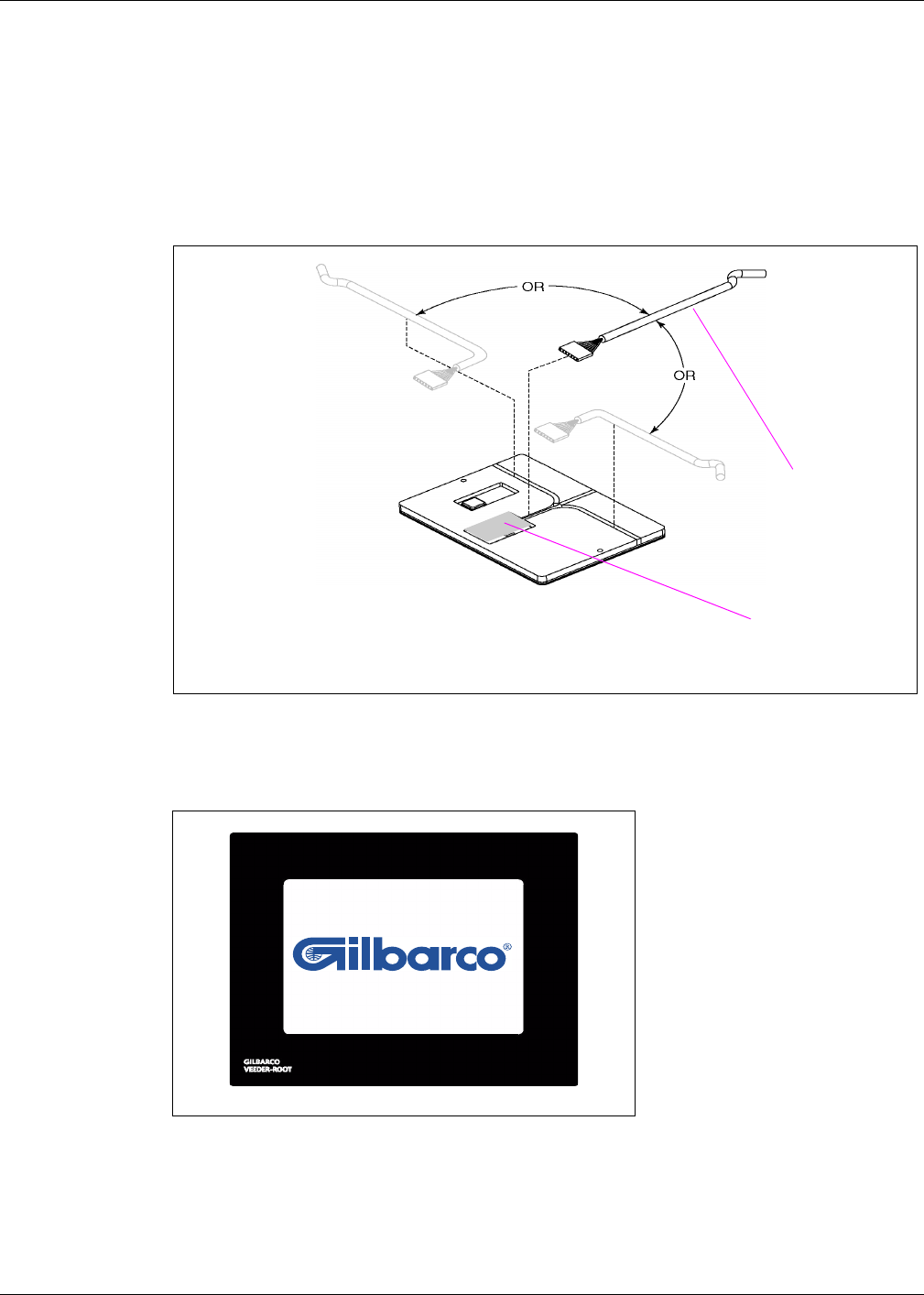
1Position Mat Reader face down.
Figure: Bottom Side of Mat Reader - Low Frequency
2Select side for ribbon cable (M01872A001) connection based on counter top configuration
requirements.
Note: The Mat Reader is designed to be placed on a counter top beside or adjacent to a cash
register or point-of-sale (POS) terminal. If properly positioned, the Mat Reader ribbon
cable will “disappear” underneath the existing POS equipment. The ribbon cable will
penetrate the counter top via the same hole used by the POS power and data cables.
Double-sided tape (not provided) may be used to secure the Mat Reader and/or the
ribbon cable in position on the counter top.
3Install strip of acrylic foam tape (K85492-72) in base of channel on side selected for ribbon
cable.
4Peel second release liner, exposing adhesive.
5Carefully connect the P1/P2 end of the ribbon cable (M01872A001) to the back side of the
Mat Reader.
Note: The cable can be plugged in from either side; the orientation does not matter. Be sure
the cable will be flat and not twisted once the Mat Reader is face up.
bottom side of
Mat Reader
7-pin cable connector
channel for ribbon cable
neoprene foam tape
acrylic foam tape
ribbon cable
7-pin Mat Reader
connectors (only
one used)
plastic channel filler
Preliminary
05/16/02
Installation
Page 20 MDE-4017B Mat Reader Assembly Kit C00016-XXX Installation Manual • May 2002
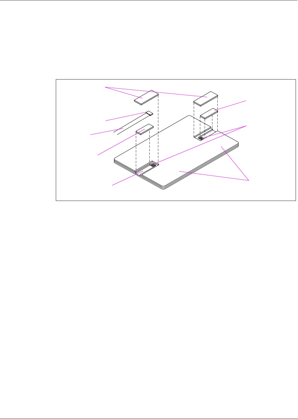
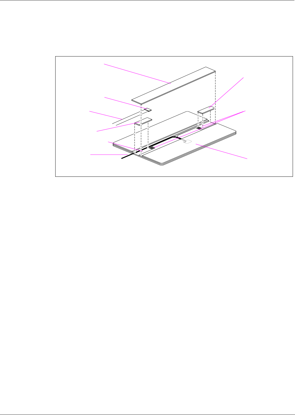
Figure: Connecting to Mat Reader - Low Frequency
6Peel release liner and install neoprene foam tape (M01870B001) over ribbon cable and sides
of channel. Foam tape should fit snugly into cutout of surrounding foam tape backer.
7On unused cable channel, install plastic filler channel (M01871B001).
8Install remaining neoprene foam tape (M01870B001) over filler channel. Foam tape should fit
snugly into cutout of surrounding foam tape backer.
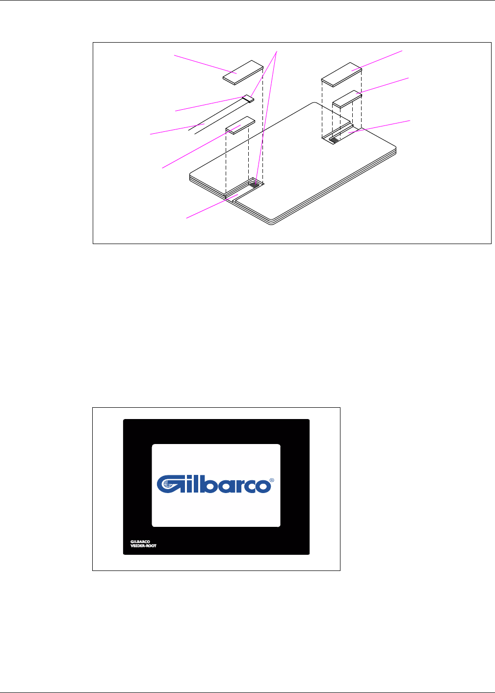
9Gently turn the Mat Reader to the face-up position.
Figure: Mat Reader - Face Up
10 Connect the loose end of the CAT-5 cable to the POS system.
Note: For a G-SITE system, the exact G-SITE system port depends on the G-SITE system
configuration. Refer to MDE-3110 PC-Based G-SITE System Installation Manual.
7-pin cable connector
channel for ribbon cable
neoprene foam tape
acrylic foam tape
ribbon cable
plastic channel filler
unused channel
neoprene foam tape
carefully connect these
Preliminary
05/16/02
Page 21 MDE-4017B Mat Reader Assembly Kit C00016-XXX Installation Manual • May 2002
Installation
Low Frequency Mini Mat Reader
1Position Mat Reader face down.
Figure: Bottom Side of Mini Mat Reader - Low Frequency
2Select side for CAT-5 cable (M01872A002) connection based on counter top configuration
requirements.
Note: The Mat Reader is designed to be placed on a counter top beside or adjacent to a cash
register or point-of-sale (POS) terminal. If properly positioned, the Mat Reader cable
will “disappear” underneath the existing POS equipment. The cable will penetrate the
counter top via the same hole used by the POS power and data cables. Double-sided
tape (not provided) may be used to secure the Mat Reader and/or the cable in position
on the counter top.
3Using fingers, spread open the precut backing for the cable routing path selected in the
previous step and lift out the neoprene material from that path. Each cable path has been precut
approximately 90 percent through. Lifting out the selected channel will cause slight tearing of
the neoprene material which is to be expected.
cable to
interface box
bottom side of Mini Mat Reader
three channels
from which to
choose one
(remove
neoprene
material from
selected path)
neoprene foam tape
(M024498B001)
carefully connect
these then cover
with neoprene
foam tape
Perform the next step by hand! Use of tools (i.e. screwdriver tip or knife blade)
could damage PCB beneath the layer of neoprene, which could render the system
inoperable and void the warranty.
CAUTION
Preliminary
05/16/02
Installation
Page 22 MDE-4017B Mat Reader Assembly Kit C00016-XXX Installation Manual • May 2002
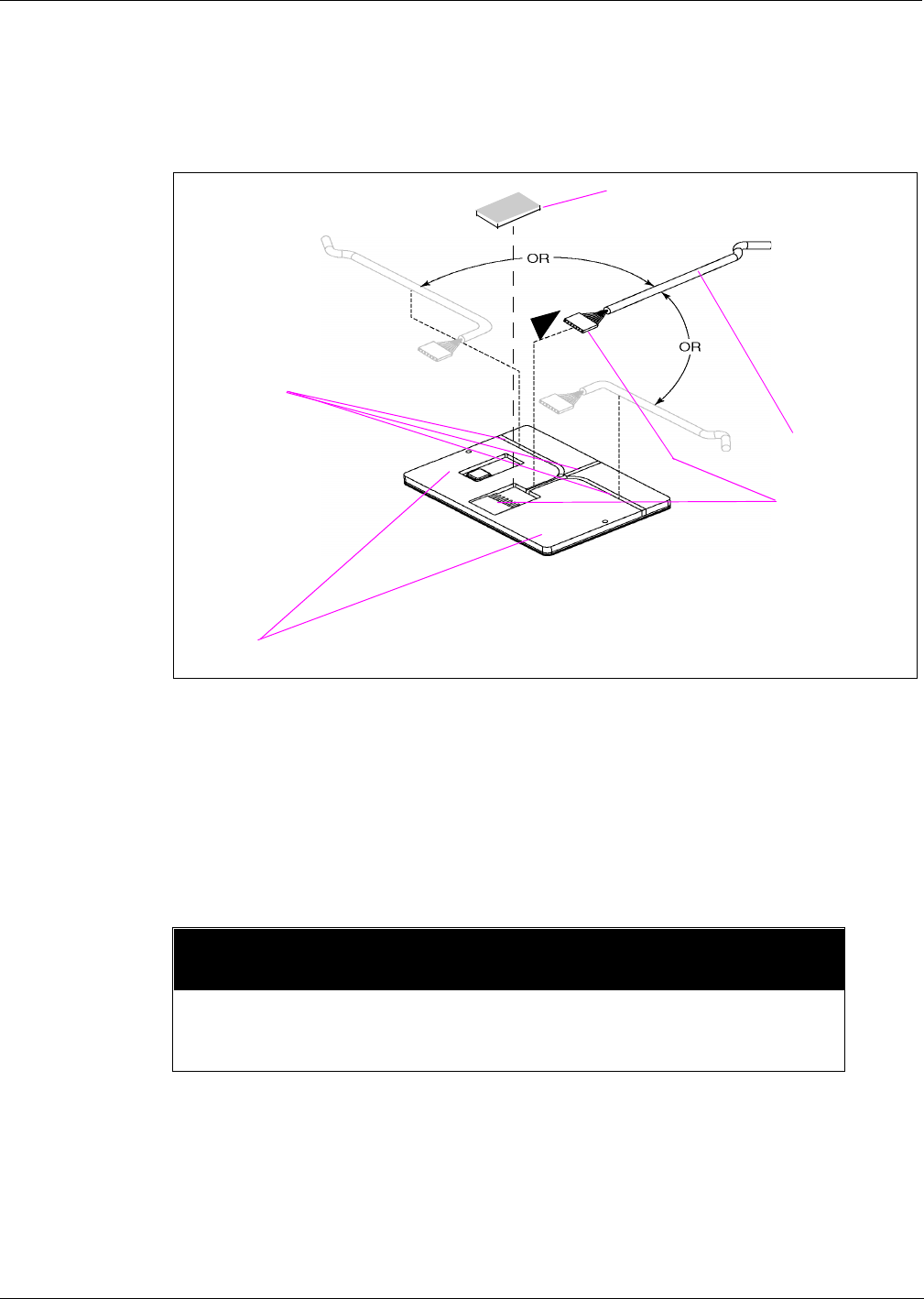
4Carefully connect the P1/P2 end of the cable (M01872A002) to the back side of the Mat
Reader, and press the cable into the cable path channel created in step 3.
5Peel the backing from the neoprene foam tape (M02498B001) and place over the P1/P2 cable
connection. Be sure to press tape down firmly so it contacts the PCB around the perimeter of
the connector.
Figure: Connecting to Mini Mat Reader - Low Frequency
6Gently turn the Mat Reader to the face-up position.
Figure: Mat Reader - Face Up
7Connect the loose end of the CAT-5 cable to the POS system.
Note: For a G-SITE system, the exact G-SITE system port depends on the G-SITE system
configuration. Refer to MDE-3110 PC-Based G-SITE System Installation Manual.
P1/P2 connector
covered by neoprene
tape
cable to
interface box
Preliminary
05/16/02
Page 23 MDE-4017B Mat Reader Assembly Kit C00016-XXX Installation Manual • May 2002
Installation
High Frequency Mat Reader
1Position Mat Reader face down.
Figure: Bottom Side of Mat Reader - High Frequency
2Select side for ribbon cable (M01872A001) connection based on counter top configuration
requirements.
Note: The Mat Reader is designed to be placed on a counter top beside or adjacent to a cash
register or point-of-sale (POS) terminal. If properly positioned, the Mat Reader ribbon
cable will “disappear” underneath the existing POS equipment. The ribbon cable will
penetrate the counter top via the same hole used by the POS power and data cables.
Double-sided tape (not provided) may be used to secure the Mat Reader and/or the
ribbon cable in position on the counter top.
3Install strip of acrylic foam tape (K85492-72) in base of channel on side selected for ribbon
cable.
4Peel second release liner, exposing adhesive.
5Carefully connect the P1/P2 end of the ribbon cable (M01872A001) to the back side of the
Mat Reader.
Note: The cable can be plugged in from either side; the orientation does not matter. Be sure
the cable will be flat and not twisted once the Mat Reader is face up.
6Carefully connect the coaxial cable to the antenna connection on the Interface Box
(M01803A002). Route the coaxial cable in the channel on the same side as the ribbon cable.
bottom side of
Mat Reader
7-pin cable connector
channel for ribbon cable
neoprene foam tape
acrylic foam tape
ribbon cable 7-pin Mat Reader
connectors (only
one used)
plastic channel filler
coaxial cable
Preliminary
05/16/02
Installation
Page 24 MDE-4017B Mat Reader Assembly Kit C00016-XXX Installation Manual • May 2002
Figure: Connecting to Mat Reader - High Frequency
7On unused cable channel, install plastic filler channel (M01871B002).
8Install neoprene foam tape (M01870B002) over filler channel, ribbon cable, and coaxial cable.
Foam tape should fit snugly into cutout of surrounding foam tape backer.
9Gently turn the Mat Reader to the face-up position.
Figure: Mat Reader - Face Up
10 Connect the loose end of the CAT-5 cable to the POS system.
Note: For a G-SITE system, the exact G-SITE system port depends on the G-SITE system
configuration. Refer to MDE-3110 PC-Based G-SITE System Installation Manual.
7-pin cable connector
channel for ribbon cable
acrylic foam tape
ribbon cable
plastic channel filler
unused channel
neoprene foam tape
carefully connect
these
coaxial cable
Preliminary
05/16/02
Page 25 MDE-4017B Mat Reader Assembly Kit C00016-XXX Installation Manual • May 2002
Installation
Connecting Power Supply
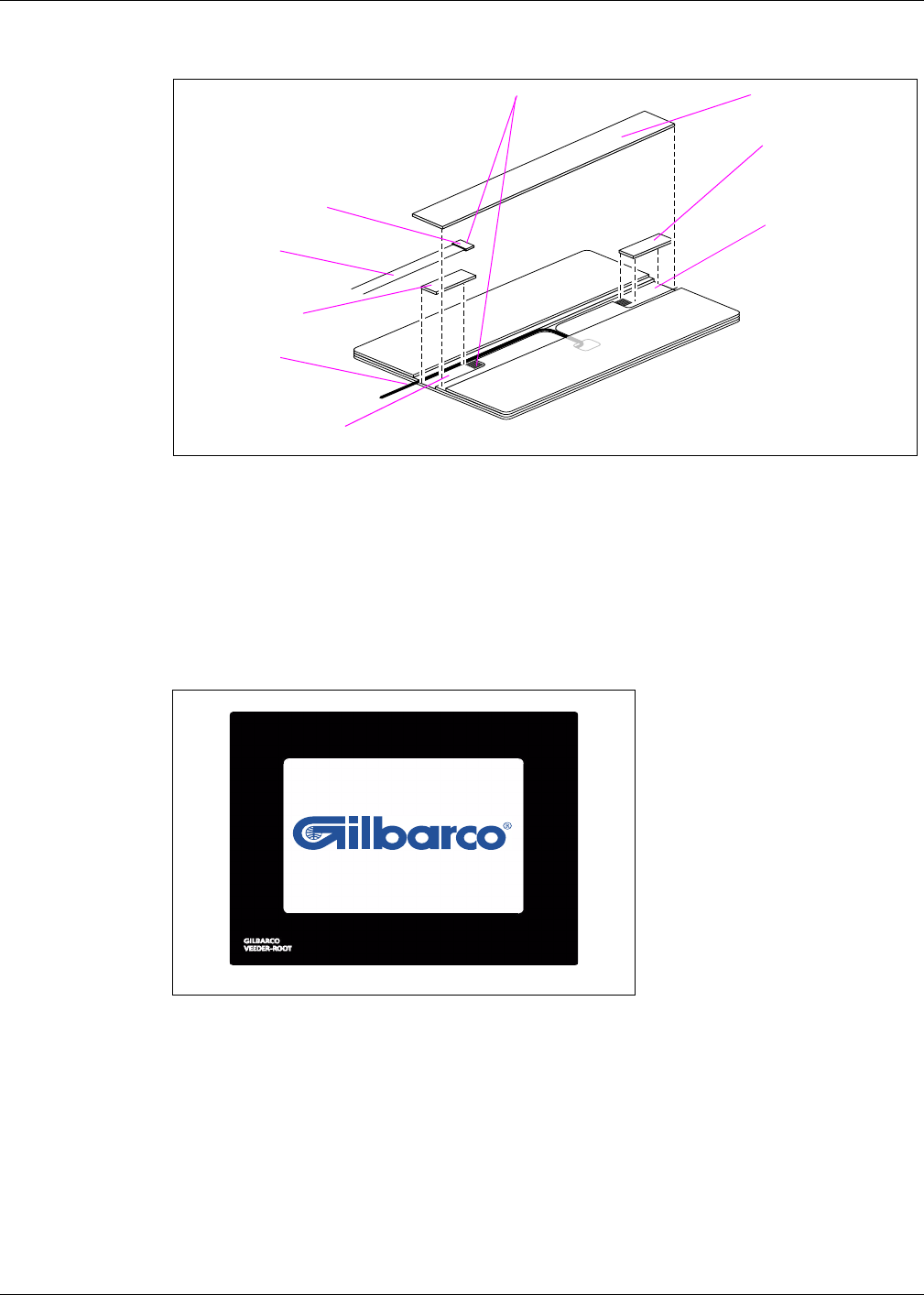
Figure: Power Supply (M01878B001)
Low and High Frequency Mat Readers
Connect the power supply (M01878B001) provided with kit as shown.
1Plug the wall-mounted transformer into the AC power outlet.
Note: If the POS is a G-SITE system, this AC power outlet must be on the same circuit as the
G-SITE system.
2Connect the plug end of the power supply cable to the JDC1 port on the Mat Reader Interface
Box (see “Figure: Connecting to Mat Reader Interface Box M01803A001” on page 18 or
“Figure: Connecting to Mat Reader Interface Box M01803A002” on page 18).
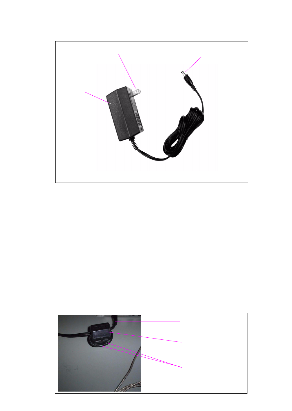
3Double loop the JDC1 end of the power supply cable through the ferrite bead (Q11433-107)
with the bead in the open position, then snap the bead shut.
Figure: Power Supply (M01878B001) Cable with Ferrite
wall-mounted
transformer
plugs into JDC1 port
plugs into AC power outlet
Q11433-107 ferrite
Power supply cable,
double looped
Power supply cable

Preliminary
05/16/02
Installation
Page 26 MDE-4017B Mat Reader Assembly Kit C00016-XXX Installation Manual • May 2002
Mini Mat Readers
Connect the power supply (M01878B001) provided with kit as shown.
1Plug the wall-mounted transformer into the AC power outlet.
Note: If the POS is a G-SITE system, this AC power outlet must be on the same circuit as the
G-SITE system.
2Connect the plug end of the power supply cable to the JDC1 port on the Mat Reader Interface
Box (see “Figure: Connecting to Mat Reader Interface Box M01803A001” on page 18).
Note: The Q11433-107 ferrite will be installed in the first step under “Low Frequency Mini
Mat Reader” on page 29 in the “Completing the Installation” section.
Preliminary
05/16/02
Page 27 MDE-4017B Mat Reader Assembly Kit C00016-XXX Installation Manual • May 2002
Installation
Completing the Installation
Low Frequency Mat Reader
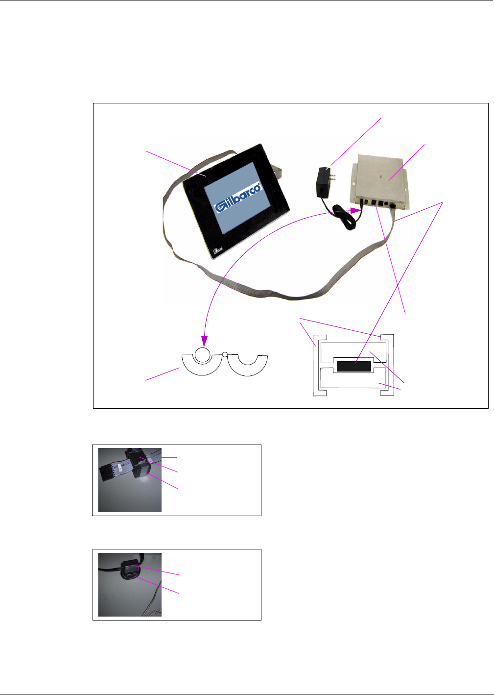
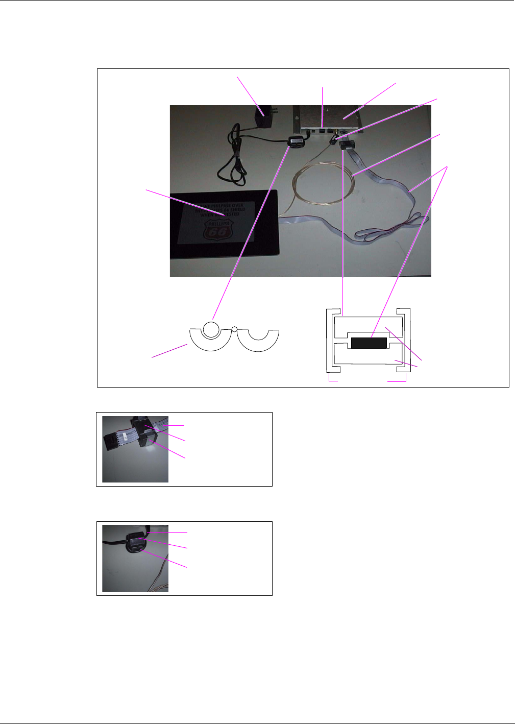
Figure: Low Frequency Mat Reader Connections
1Install both ferrite halves Q11433-110 on ribbon cable, and secure with steep clips, as shown.
2Be sure clip-on ferrite Q11433-107 is on interface box power supply cable (double loop).
3Dress all cables and secure with stick on cable clamps (Q13459-01).
CAT-5 cable
connects here
power supply
interface box
Mat Reader
Q11433-107 ferrite Q11433-110 ferrite
halves
steel clips
ribbon cable
Ribbon cable
Q11433-110 ferrite
Steel clip
Q11433-107 ferrite
Power supply cable,
double looped
Power supply cable
Preliminary
05/16/02
Installation
Page 28 MDE-4017B Mat Reader Assembly Kit C00016-XXX Installation Manual • May 2002
4Install M01868A001 UL/FCC decal, as appropriate, as shown in “Figure: Mat Reader
Interface Box Mounting Holes” on page 17.
5Clean up the work area.
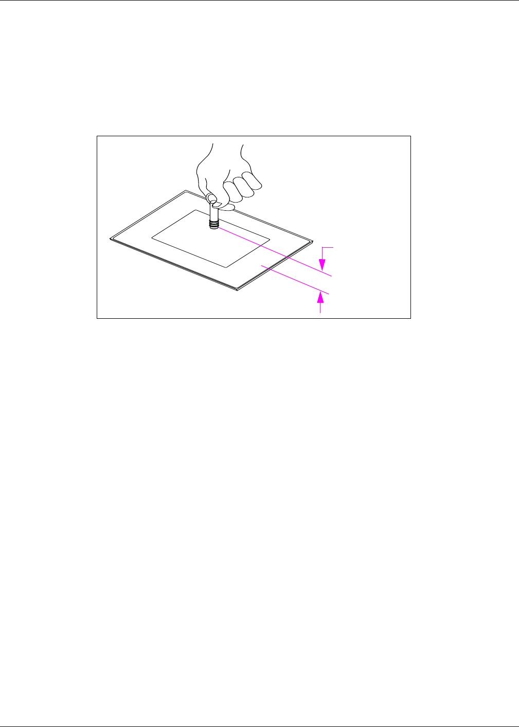
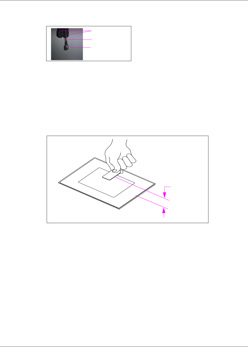
6Verify the keytag can be read by the mat reader within the specified range.
Figure: Low Frequency Mat Reader Read Verification
7Go to “Commissioning and Warranty Information” on page 33.
2.0-4.0 inches
(5-10 cm)
Preliminary
05/16/02
Page 29 MDE-4017B Mat Reader Assembly Kit C00016-XXX Installation Manual • May 2002
Installation
Low Frequency Mini Mat Reader
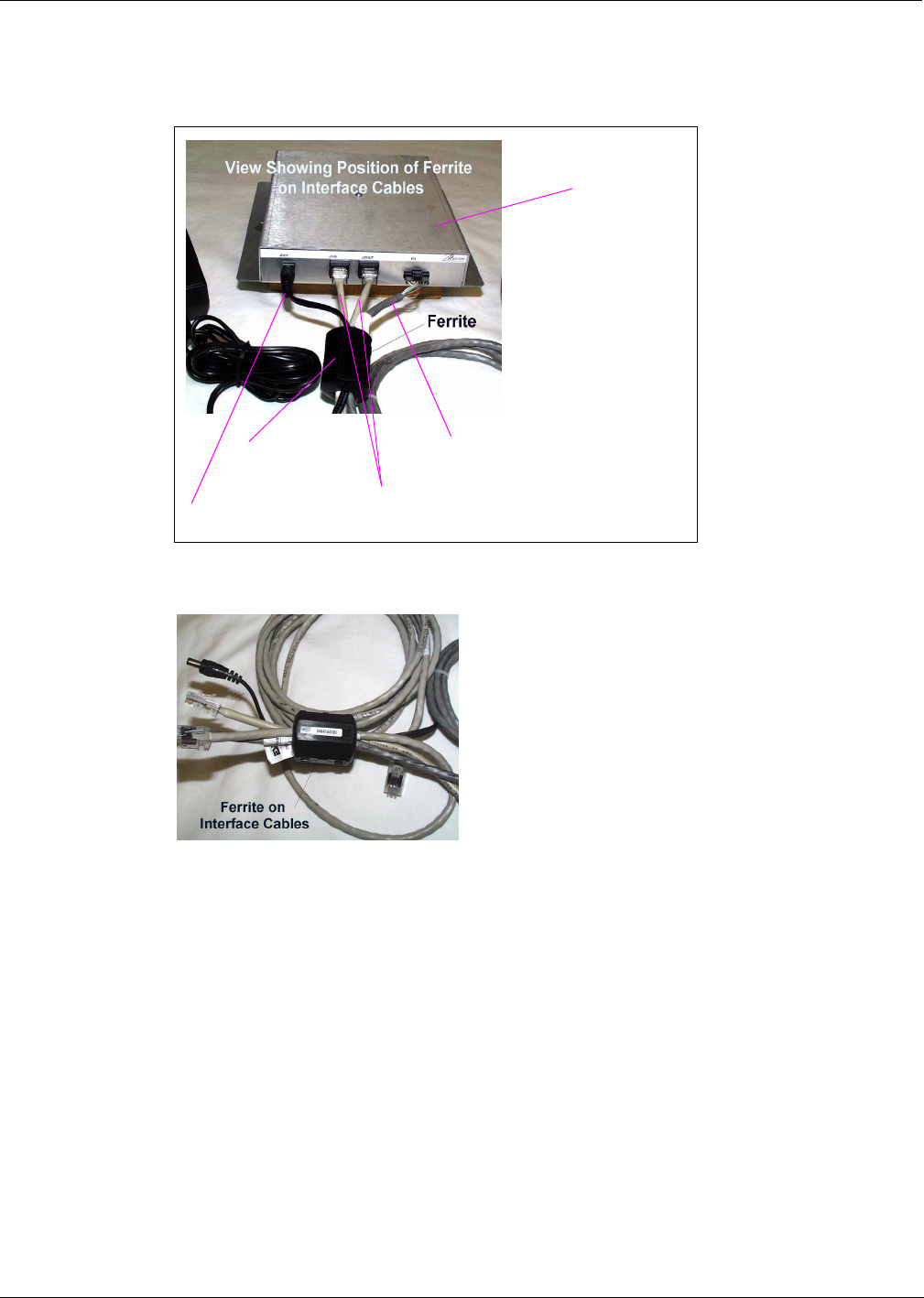
Figure: Low Frequency Mini Mat Reader Connections
1Route all cables near interface box end through Q11433-107 ferrite and snap ferrite closed.
2Dress all cables and secure with stick on cable clamps (Q13459-01).
3Install M01868A003 UL/FCC decal, as appropriate, as shown in “Figure: Mat Reader
Interface Box Mounting Holes” on page 17.
4Clean up the work area.
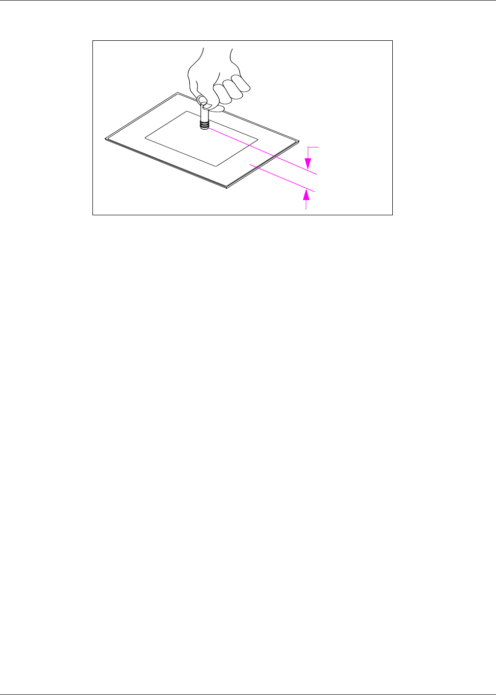
5Verify the keytag can be read by the mat reader within the specified range (see “Figure: Low
Frequency Mini Mat Reader Read Verification” on page 30).
power supply cable
CAT-5 cables
interface box-to-mat
reader cable
Q11433-107
ferrite
interface box
Preliminary
05/16/02
Page 31 MDE-4017B Mat Reader Assembly Kit C00016-XXX Installation Manual • May 2002
Installation
High Frequency Mat Reader
Figure: High Frequency Mat Reader Connections
1Install both ferrite halves Q11433-110 on ribbon cable, and secure with steep clips, as shown.
2Be sure clip-on ferrite Q11433-107 is on interface box power supply cable (double loop).
CAT-5 cable
connects here
power supply interface box
Q11433-107 ferrite Q11433-110 ferrite
halves
steel clips
ribbon cable
Coaxial cable
Q11433-106
ferrite
mat reader
Ribbon cable
Q11433-110 ferrite
Steel clip
Q11433-107 ferrite
Power supply cable,
double looped
Power supply cable
Preliminary
05/16/02
Installation
Page 32 MDE-4017B Mat Reader Assembly Kit C00016-XXX Installation Manual • May 2002
3Install clip-on ferrite (Q11433-106) in pass-through configuration on coaxial cable at Interface
Box connection.
4Dress all cables and secure with stick on cable clamps (Q13459-01).
5Install M01868A002 UL/FCC decal, as appropriate, as shown in “Figure: Mat Reader
Interface Box Mounting Holes” on page 17.
6Clean up the work area.
7Verify the keytag can be read by the mat reader within the specified range.
Figure: High Frequency Mat Reader Read Verification
8Go to “Commissioning and Warranty Information” on page 33.
Q11433-106 ferrite
Coaxial cable
SMA connector
1.5-3.0 inches
(3.81-7.62 cm)

Preliminary
05/16/02
Page 33 MDE-4017B Mat Reader Assembly Kit C00016-XXX Installation Manual • May 2002
Commissioning and Warranty Information
Commissioning and Warranty Information
Upon completion and testing the Mat Reader system, the installing contractor must call the
Gilbarco Call Center at 1-888-800-7498 to register the installation and activate the warranty.
Note the installed unit’s full Model Number (C00016-XXX) and serial number before making
this call.
•All Mat Readers have a one-year parts only warranty.
Note: Parts are to be returned through and obtained from the local Gilbarco distributor.
•Labor warranty, if any, is unit and customer specific.
Gilbarco strongly recommends using only Gilbarco trained ASCs (Authorized Service
Contractors) to perform service on the units. Use of non-authorized service personnel to repair
or service these units may void warranty. Call your local distributor for service.

Preliminary
05/16/02
Commissioning and Warranty Information
© 2002 Gilbarco Inc.
7300 West Friendly Avenue • Post Office Box 22087
Greensboro, North Carolina 27420
Phone (336) 547-5000 • http://www.gilbarco.com • Printed in the U.S.A.
MDE-4017B Mat Reader Assembly Kit C00016-XXX Installation Manual • May 2002
G-SITE® and Gilbarco® are regsitered trademarks of Gilbarco Inc. GOLDSM is a service mark of Gilbarco Inc.
Corian® is a registered trademark of E.I. Du Pont De Nemours and Company. Formica® is a registered trademark of Formica Corporation
IC® is a registered trademark of Industry Canada. Phillips® is a registered trademark of Phillips Screw Company. UL® is a registered
trademark of Underwriters’ Laboratories, Inc. Zircon® is a registered trademark of Zircon International Inc.