Gilbarco GCM Contactless Smart Card Interface User Manual Manual Cover
Gilbarco Inc. Contactless Smart Card Interface Manual Cover
UserManual.wiki
>
Gilbarco
>
GCM User Manual
Manual
Navigation menu
Upload a User Manual
Namespaces
Wiki Guide
HTML
PDF
Info
Views
User Manual
Discussion / Help
Navigation

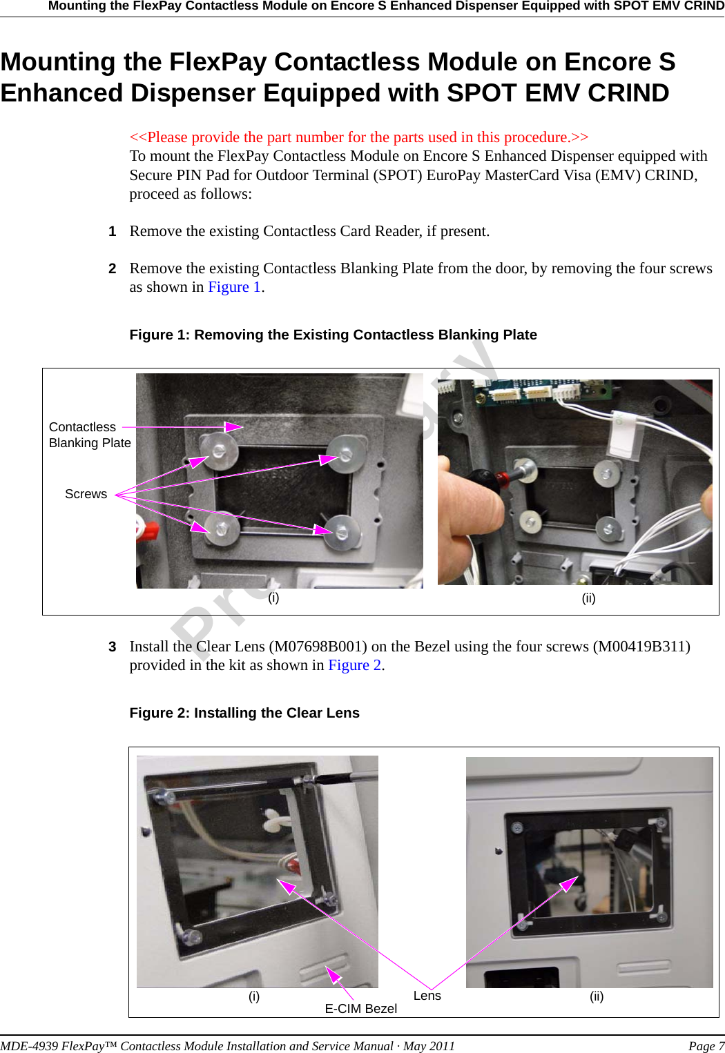
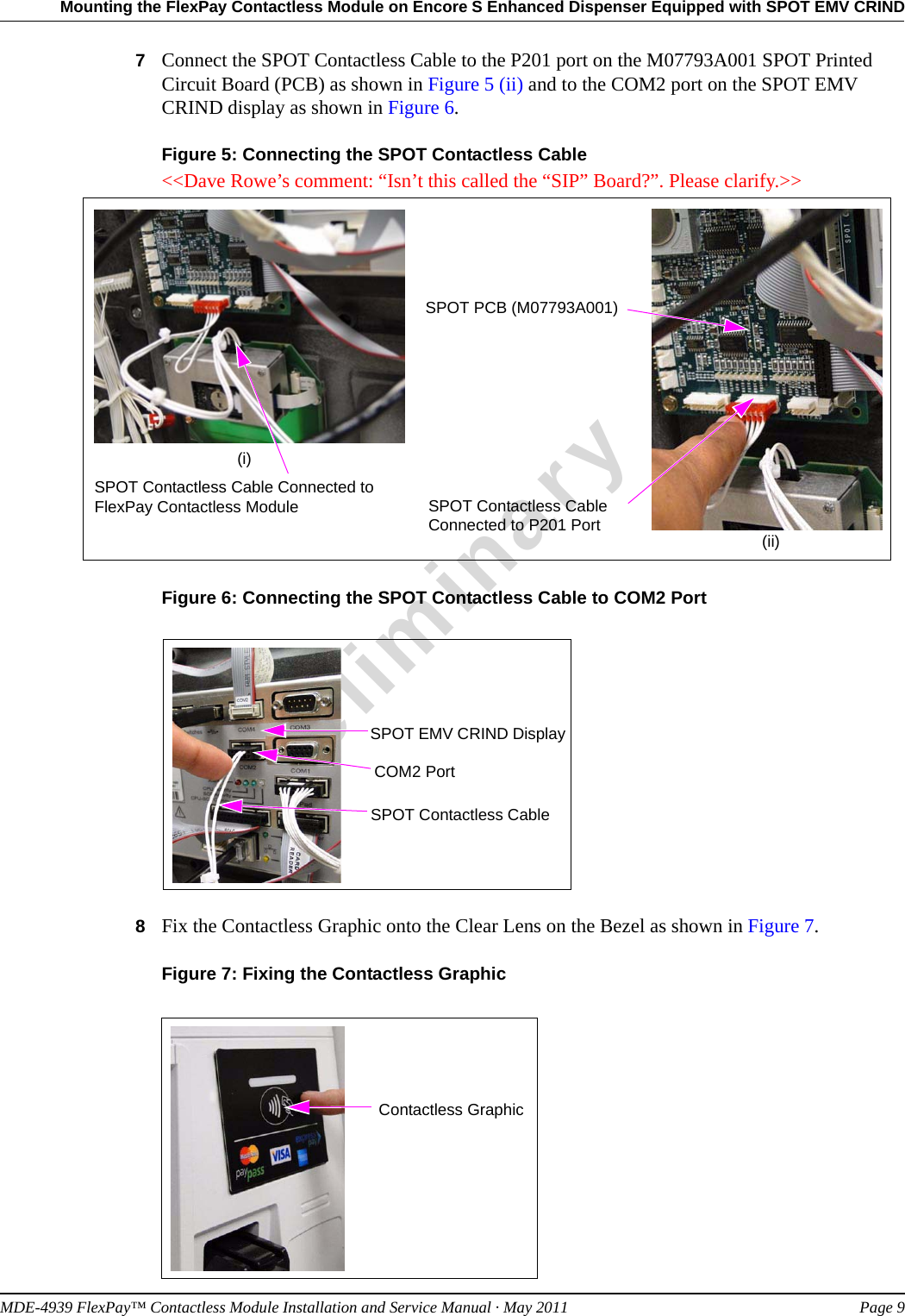
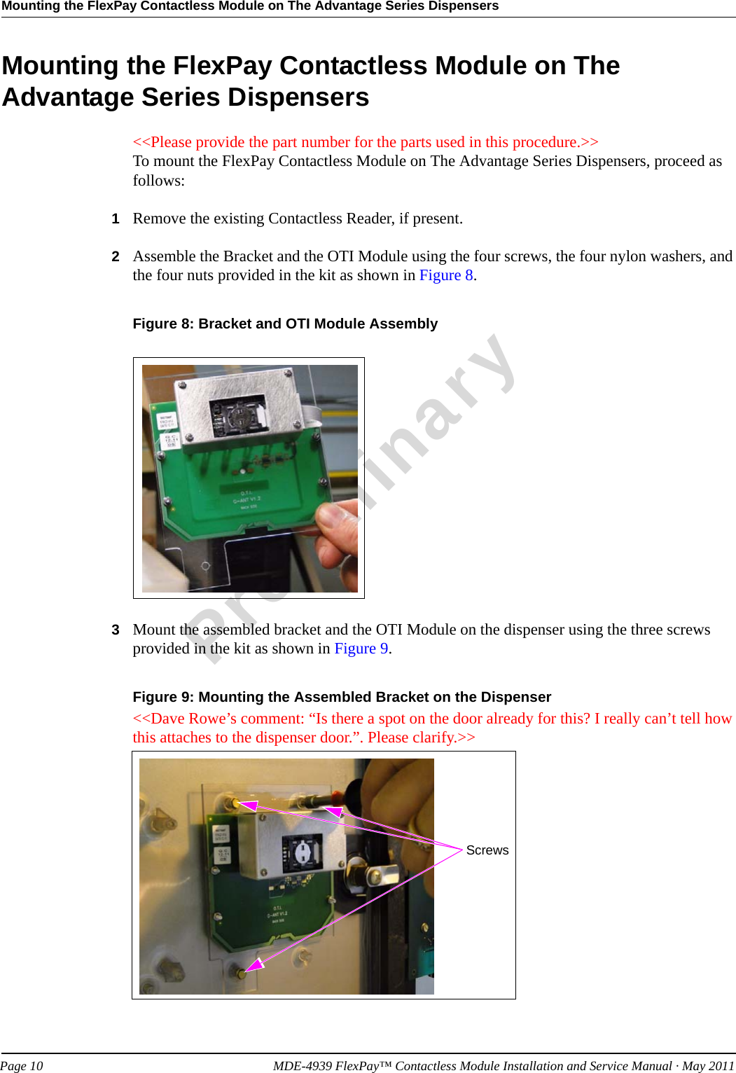
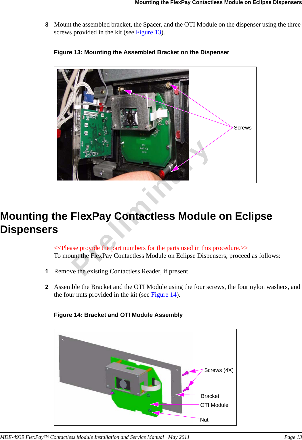
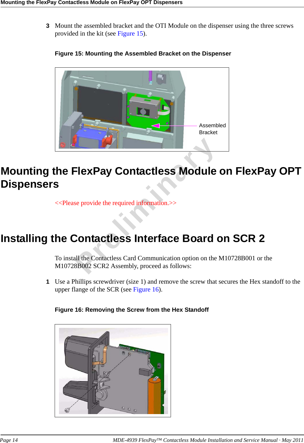
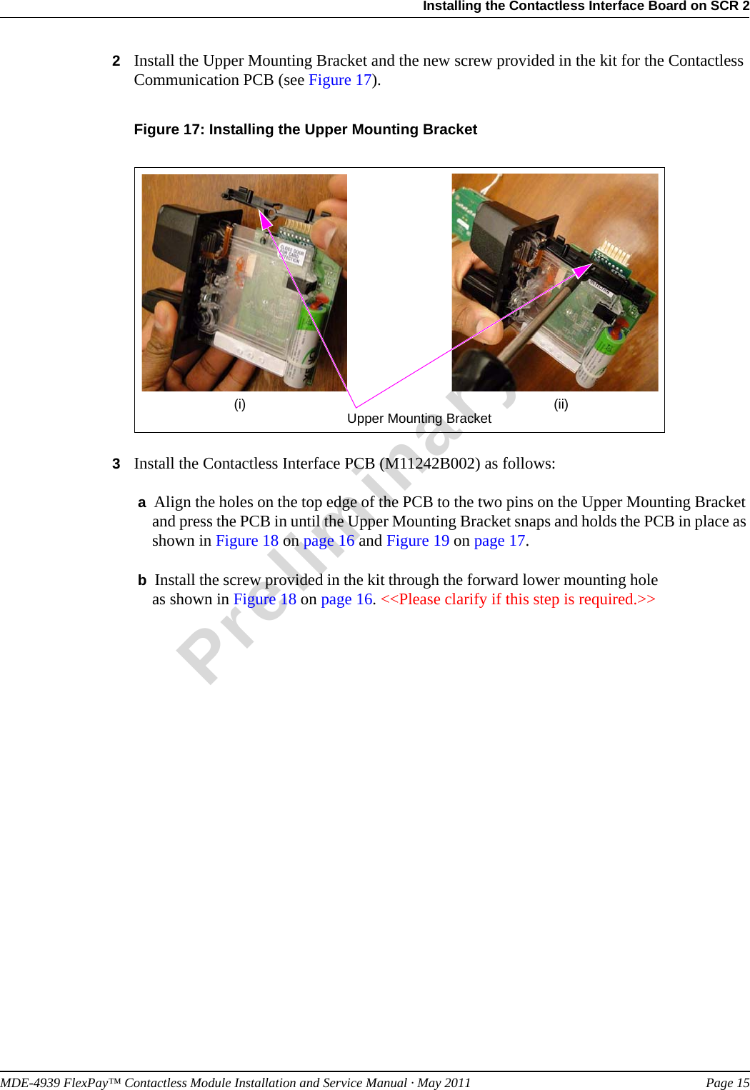
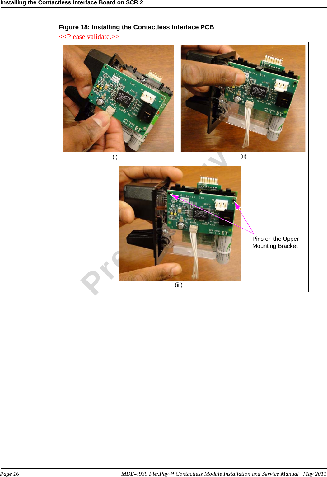
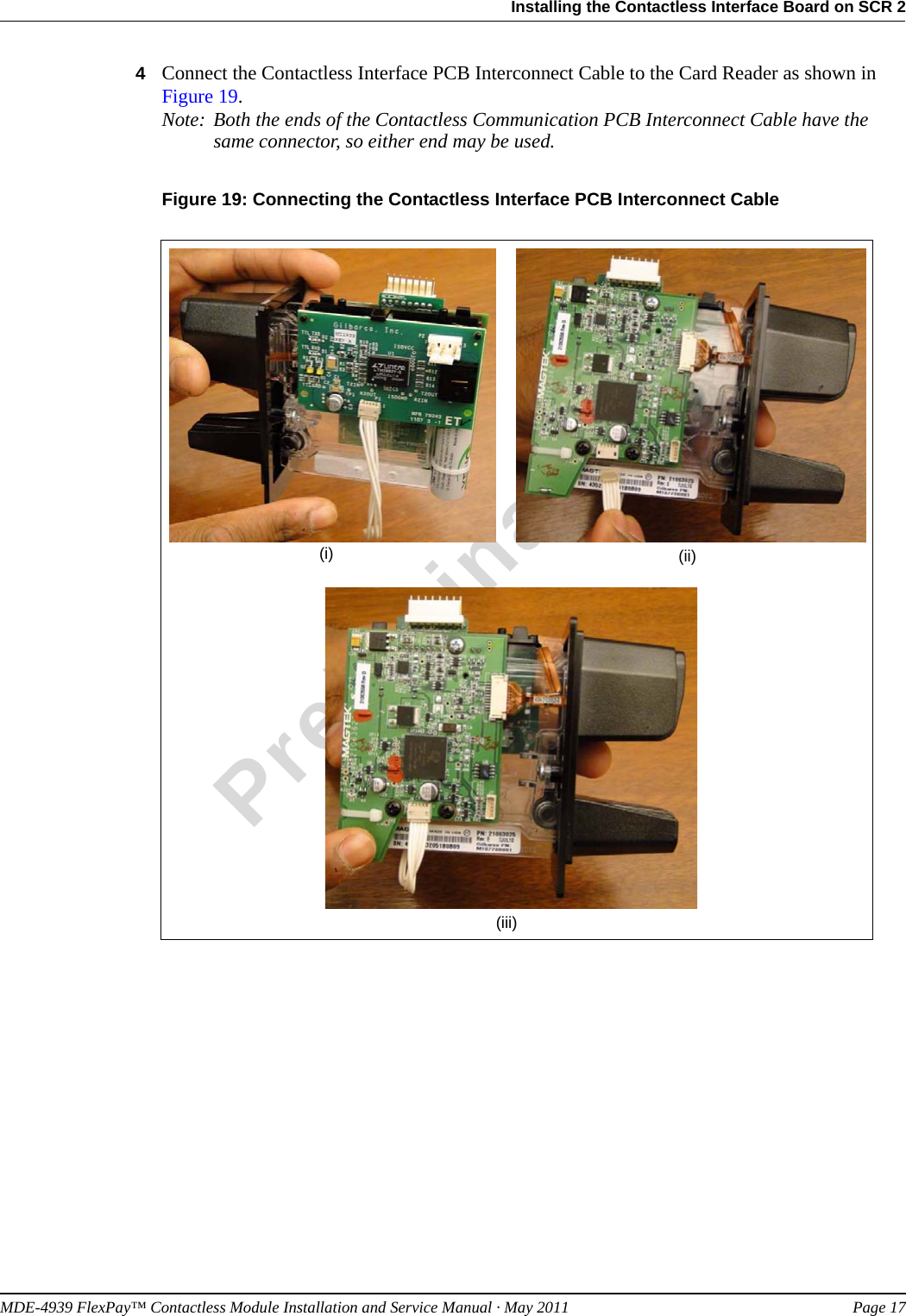
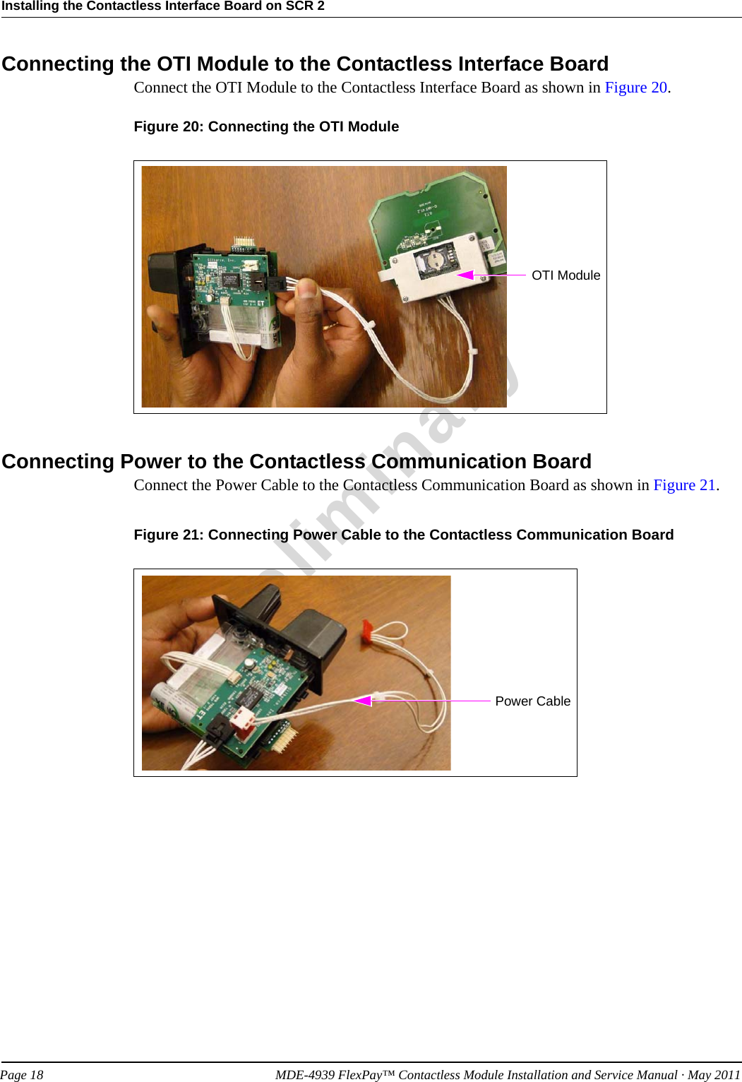
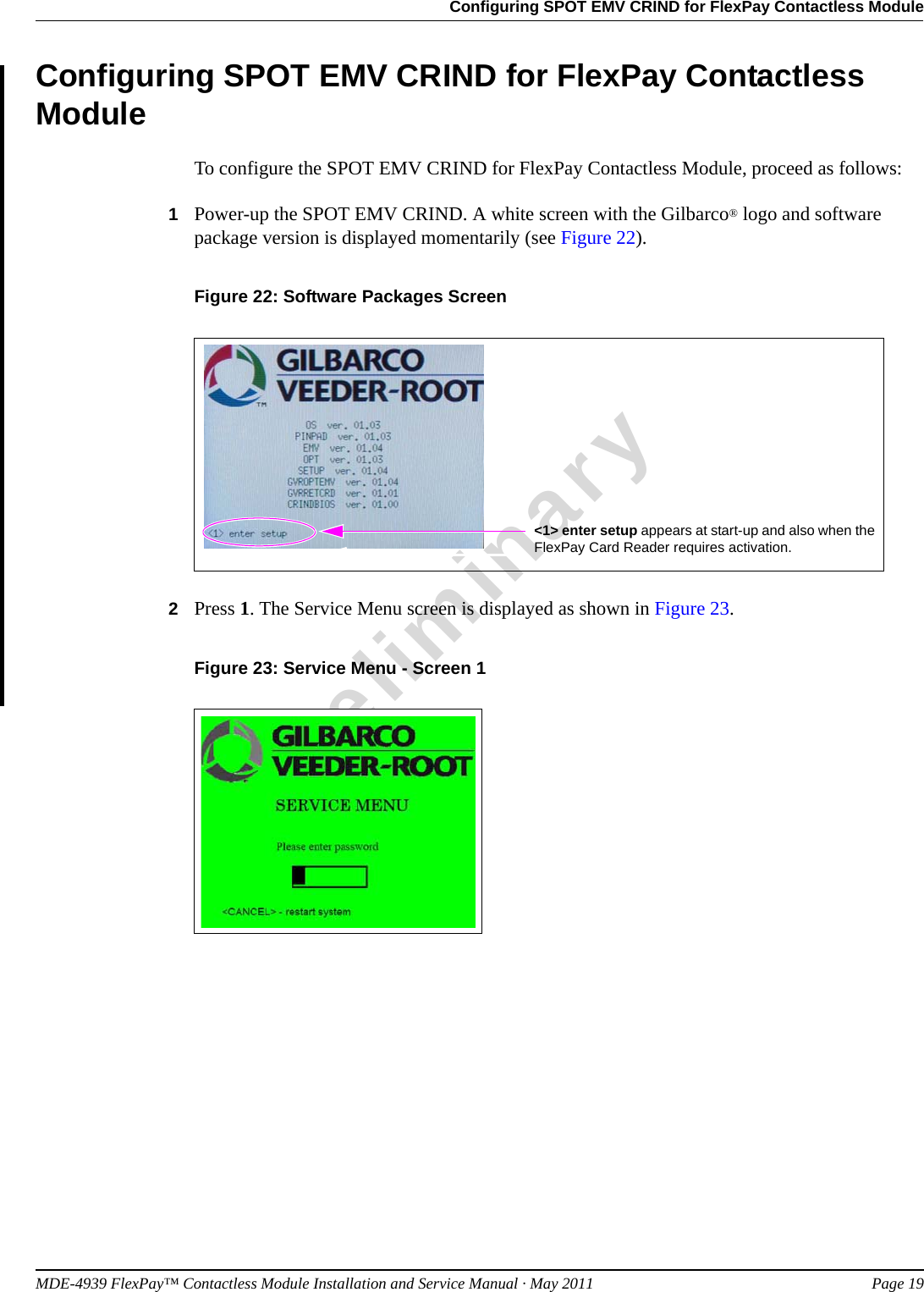
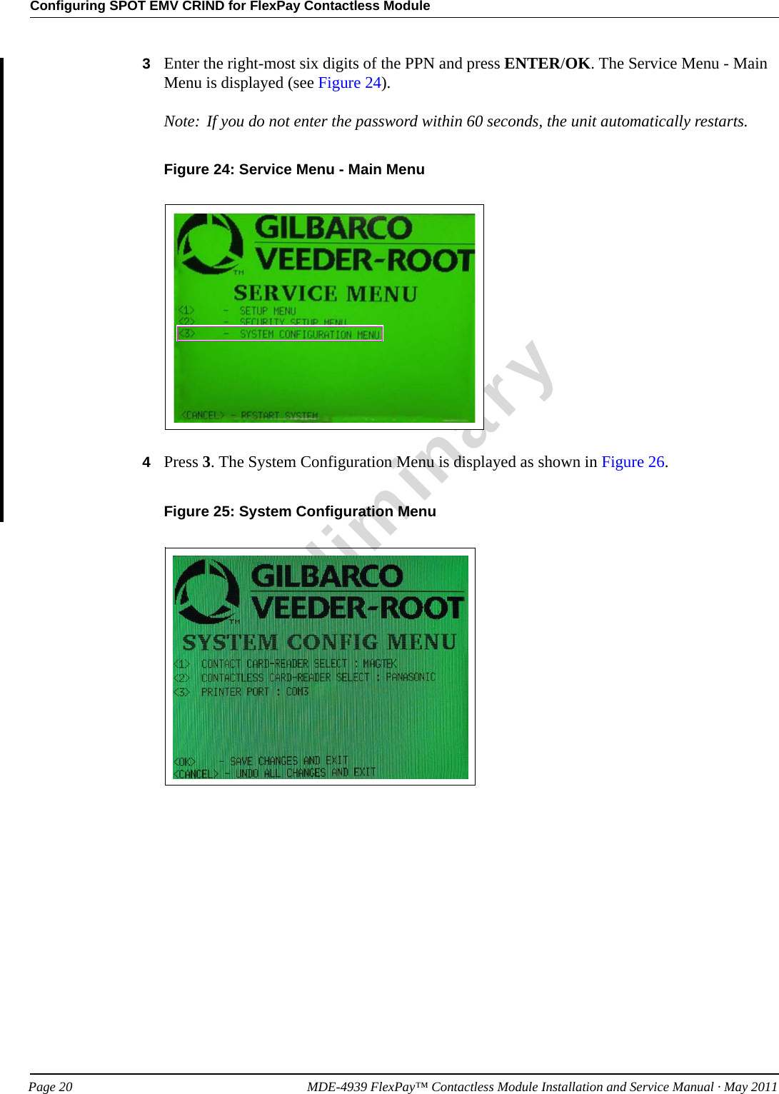
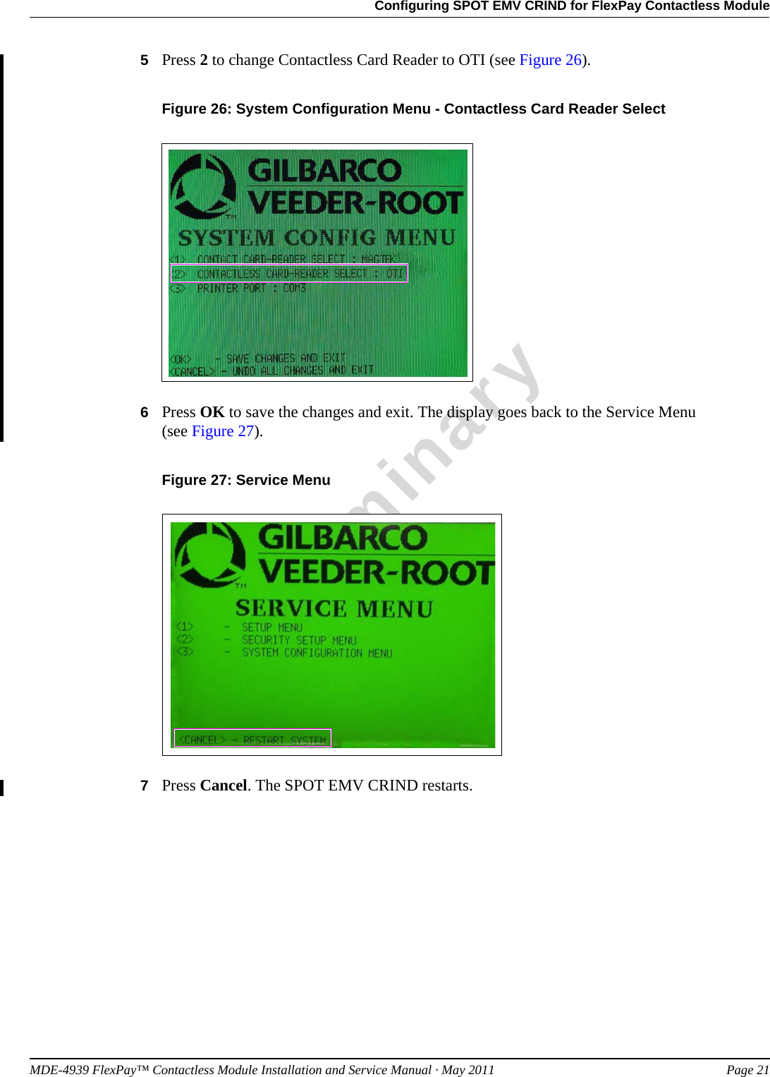
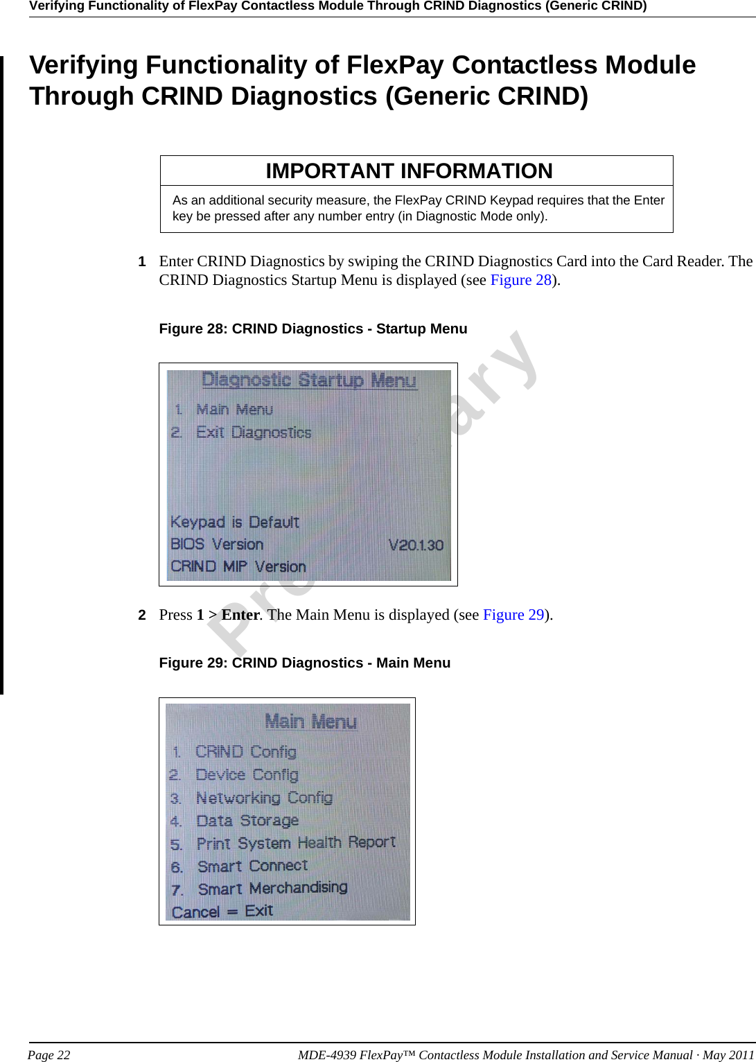
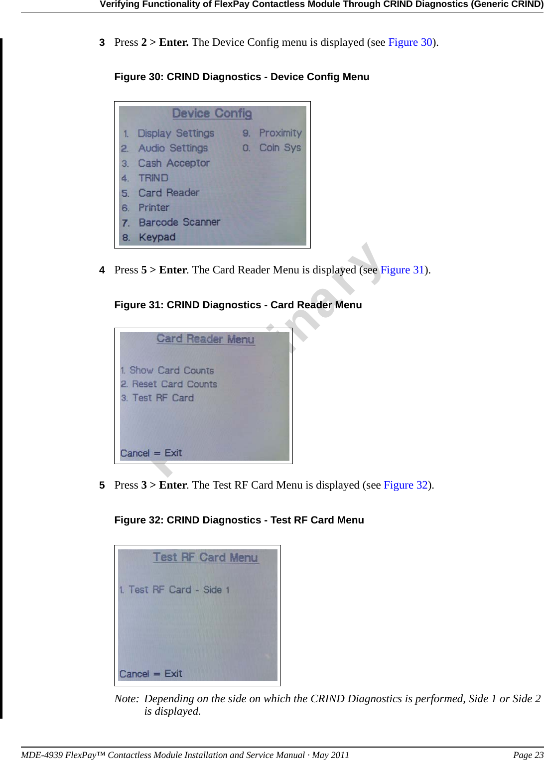
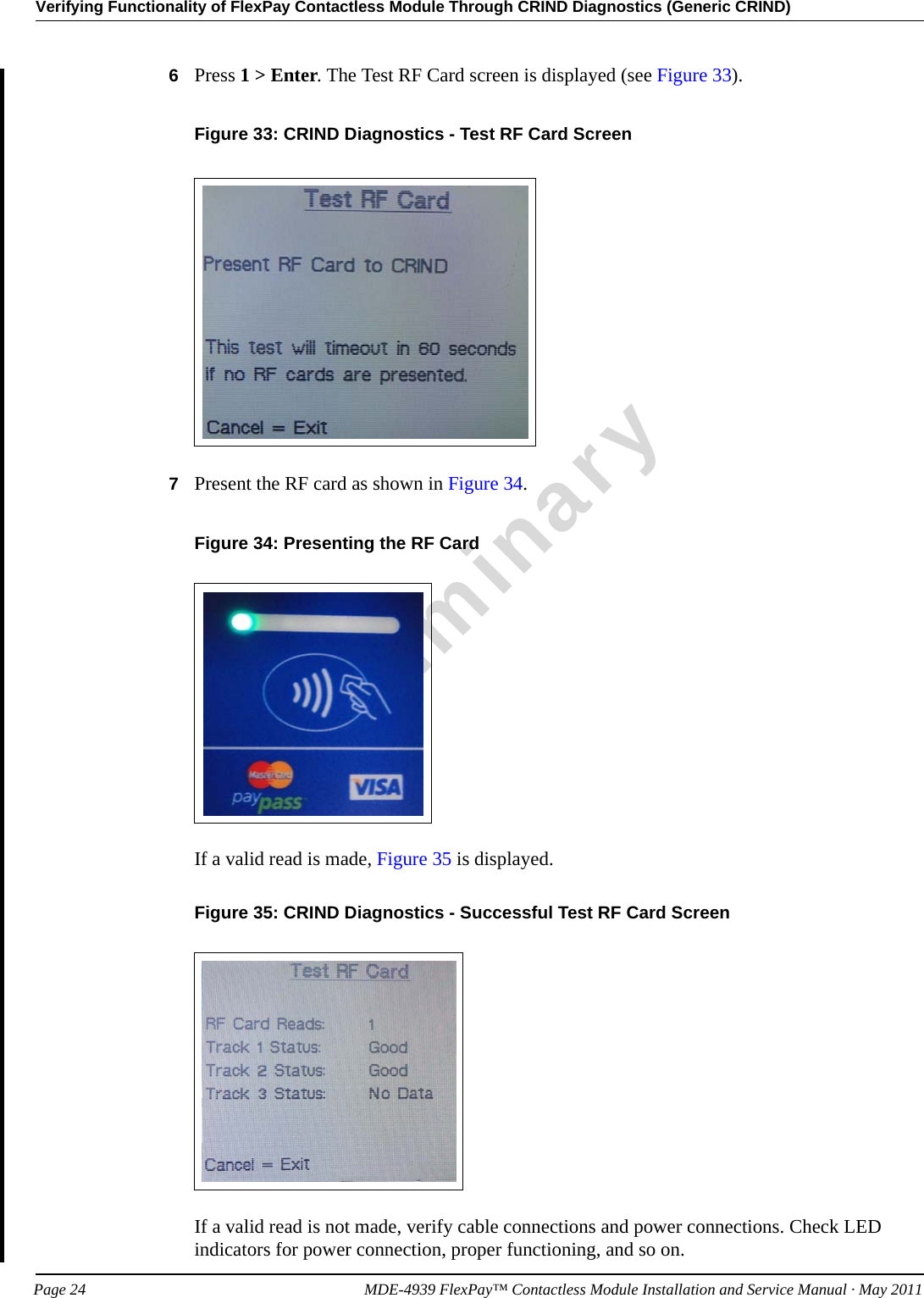
![Mounting the FlexPay Contactless Module on Encore S Enhanced Dispenser Equipped with SPOT EMV CRINDPreliminaryPage 8 MDE-4939 FlexPay™ Contactless Module Installation and Service Manual · May 20114Assemble the Bracket and the FlexPay Contactless Module using the four screws, four Nylon Washers, and the four nuts provided in the kit (see Figure 3).Figure 3: Bracket and the FlexPay Contactless Module AssemblyBracketScrewsFlexPay Contactless Module5Mount the Bracket and the FlexPay Contactless Module Assembly onto the E-CIM Bezel using the four screws provided in the kit (see Figure 4).Figure 4: Mounting the Bracket and the FlexPay Contactless Module Assembly6Connect the SPOT Contactless Cable to the FlexPay Contactless Module [see Figure 5 (i)].](https://usermanual.wiki/Gilbarco/GCM/User-Guide-1471072-Page-9.png)