Gilbarco GCM Contactless Smart Card Interface User Manual Manual Cover
Gilbarco Inc. Contactless Smart Card Interface Manual Cover
Gilbarco >
Manual

5015 B.U. Bowman Drive Buford, GA 30518 USA Voice: 770-831-8048 Fax: 770-831-8598
Certification Exhibit
FCC ID: N6SGCM
IC: 827B-GCM
FCC Rule Part: 15.225
IC Radio Standards Specification: RSS-210
ACS Report Number: 11-0087.W06.11.A
Manufacturer: Gilbarco, Inc.
Model: FlexPay Contactless
Manual

MDE-4939 FlexPay™ Contactless Module Installation and Service Manual · May 2011 Page 1
Preliminary
05/05/11
Introduction
Purpose
This document provides instructions to mount the FlexPay™ Contactless Module and to install
the Contactless Interface Board on Secure Card Reader 2 (SCR2).
This equipment has been tested and found to comply with the limits pursuant to Part 15
of the Federal Communications Commission (FCC) Rules. These limits are designed to
provide reasonable protection against harmful interference when the equipment is
operated in a commercial environment. This equipment generates, uses, and radiates
radio frequency energy. This equipment must be installed and used in accordance with
the instruction manual to avoid harmful interference to radio communications. Operation
of this equipment in a residential area may cause harmful interference. In this case the
user has to correct the interference at his own expense. Any change or modification
must be approved by the manufacturer to allow the user to operate this equipment
safely.
The long term characteristics or the possible physiological effects of radio frequency
electromagnetic fields have not been investigated by Underwriters’ Laboratories, Inc.
(UL®).
IMPORTANT INFORMATION
Industry Canada Regulation:
This device complies with Industry Canada licence-exempt RSS standard(s). Operation
is subject to the following two conditions:
• This device may not cause interference
• This device must accept any interference including interference that may cause
undesired operation of the device.
Under Industry Canada regulations, this radio transmitter may only operate using an
antenna of a type and maximum (or lesser) gain approved for the transmitter by Industry
Canada. To reduce potential radio interference to other users, the antenna type and its
gain should be so chosen that the equivalent isotropically radiated power (e.i.r.p.) is not
more than that necessary for successful communication.
IMPORTANT INFORMATION
MDE-4939
FlexPay™ Contactless Module Installation and
Service Manual
May 2011

Introduction
Preliminary
Page 2 MDE-4939 FlexPay™ Contactless Module Installation and Service Manual · May 2011
Table of Contents
Topic Page
Introduction 1
Important Safety Information 5
Mounting the FlexPay Contactless Module on Encore S Enhanced Dispenser Equipped with SPOT EMV CRIND 7
Mounting the FlexPay Contactless Module on The Advantage Series Dispensers 10
Mounting the FlexPay Contactless Module on Encore 300 and Encore 500 Dispensers 11
Mounting the Contactless OTI Module on Encore 300 (Pre-EMV) Dispensers 12
Mounting the FlexPay Contactless Module on Encore 500 S Dispensers 12
Mounting the FlexPay Contactless Module on Eclipse Dispensers 13
Mounting the FlexPay Contactless Module on FlexPay OPT Dispensers 13
Installing the Contactless Interface Board on SCR 2 14
Configuring SPOT EMV CRIND for FlexPay Contactless Module 19
Verifying Functionality of FlexPay Contactless Module Through CRIND Diagnostics (Generic CRIND) 22
Affixing FlexPay Contactless FCC Label 25
Required Tools
The following tools are required for installation of the Contactless Interface Board:
• Phillips® Screwdriver
• Small Channel Locks or Pliers
• 1/4-inch Nut Driver or Socket
Parts List
Encore® S Enhanced Dispensers - M12027K001
The following table lists the parts included in the M12027K001 kit:
Item Description Part Number Quantity
1Contactless Antenna Assembly M11697A001 1
2Contactless Antenna Spacer M12032B001 1
3Thread Forming Screw Q11677-24 4
4Nylon Washer M12184B001 4
5TRIND® E-CIM Lens M07698B001 1
6Gasket TRIND Lens M07715B002 1
7Thread Forming Screw M00419B311 4
8Cable <<Please provide the
required part number.>>
1
9Graphic <<Please provide the
required part number.>>
1
The Advantage® Series Dispensers - M12024K001
The following table lists the parts included in the M12024K001 kit:
Item Description Part Number Quantity
1Contactless Antenna Assembly M11697A001 1
2Contactless Antenna Bracket M11800B001 1
3Contactless Antenna Spacer M12032B001 1

MDE-4939 FlexPay™ Contactless Module Installation and Service Manual · May 2011 Page 3
Introduction
Preliminary
Encore 300 and Encore 500 Dispensers - M12025K001
The following table lists the parts included in the M12025K001 kit:
Item Description Part Number Quantity
1Contactless Antenna Assembly M11697A001 1
2Contactless Antenna Bracket M11802B001 1
3Contactless Antenna Spacer M12032B002 1
4Thread Forming Screw Q11677-24 2
5Screw Phillips Pan Head Sems Metric Q12845-36 4
6Hex Nut Metric M01114B001 4
7Lens TRIND Display Window M01234B001 1
8TRIND Blanking Panel Gasket M01160B001 1
9Thread Forming Screw M00419B117 4
10 Nylon Washer M12184B001 4
11 Cable <<Please provide the
required part number.>>
1
Encore 300 (Pre-EMV) Dispensers - M12025K002
The following table lists the parts included in the M12025K002 kit:
Item Description Part Number Quantity
1Contactless Antenna Assembly M11697A001 1
2Contactless Antenna Bracket M11802B001 1
3Thread Forming Screw Q11677-24 2
4Screw Phillips Pan Head Sems Metric Q12845-36 4
5Hex Nut Metric M01114B001 4
6Lens TRIND Display Window M01234B001 1
7TRIND Blanking Panel Gasket M01160B001 1
8Thread Forming Screw M00419B117 4
9Nylon Washer M12184B001 4
10 Cable <<Please provide the
required part number.>>
1
11 Cable <<Please provide the
required part number.>>
1
Encore 500 S Dispensers - M12026K001
The following table lists the parts included in the M12026K001 kit:
4Thread Forming Screw Q11677-24 4
5Screw Phillips Pan Head Sems Metric Q12845-36 4
6Hex Nut Metric M01114B001 4
7Nylon Washer M12184B001 4
8Cable <<Please provide the
required part number.>>
1
Item Description Part Number Quantity
1Contactless Antenna Assembly M11697A001 1
2Contactless Antenna Bracket M11803B001 1
3Contactless Antenna Spacer M12032B002 1
Item Description Part Number Quantity

Introduction
Preliminary
Page 4 MDE-4939 FlexPay™ Contactless Module Installation and Service Manual · May 2011
Eclipse® Dispensers - M12028K001
The following table lists the parts included in the M12028K001 kit:
Item Description Part Number Quantity
1Contactless Antenna Assembly M11697A001 1
2Contactless Antenna Bracket M11801B001 1
3Thread Forming Screw Q11677-24 2
4Screw Phillips Pan Head Sems Metric Q12845-36 4
5Hex Nut Metric M01114B001 4
6Lens TRIND Indicator M01405B001 1
7Gasket TRIND Lens M01406B001 1
8Screw Metric Pphd Type 25(Bt) M00697B010 6
9Cable <<Please provide the
required part number.>>
1
10 Graphics <<Please provide the
required part number.>>
1
FlexPay OPT Dispensers - M12029K001
The following table lists the parts included in the M12029K001 kit:
Item Description Part Number Quantity
1Contactless Antenna Assembly M11697A001 1
2Thread Forming Screw Q11677-24 4
3Nylon Washer M12184B001 4
Related Documents
<<Please provide the required information.>>
Abbreviations and Acronyms
Term Description
CRIND®Card Reader IN Dispenser
EMV EuroPay MasterCard® Visa®
FCC Federal Communications Commission
OPT Outdoor Payment Terminal
PCB Printed Circuit Board
SCR Secure Card Reader
SPOT Secure PIN Pad for Outdoor Terminal
TCR Tribrid Card Reader
UL Underwriters’ Laboratories
4Thread Forming Screw Q11677-24 3
5Screw Phillips Pan Head Sems Metric Q12845-36 4
6Hex Nut Metric M01114B001 4
7Nylon Washer M12184B001 4
8Cable <<Please provide the
required part number.>>
1
Item Description Part Number Quantity
MDE-4939 FlexPay™ Contactless Module Installation and Service Manual · May 2011 Page 5
Important Safety Information
Preliminary
Important Safety Information
Note: Save this Important Safety Information section in a
readily accessible location.
This section introduces the hazards and safety precautions
associated with installing, inspecting, maintaining, or servicing
this product. Before performing any task on this product, read
this safety information and the applicable sections in this
manual, where additional hazards and safety precautions for
your task will be found. Fire, explosion, electrical shock, or
pressure release could occur and cause death or serious injury,
if these safe service procedures are not followed.
Preliminary Precautions
You are working in a potentially dangerous environment of
flammable fuels, vapors, and high voltage or pressures. Only
trained or authorized individuals knowledgeable in the related
procedures should install, inspect, maintain, or service this
equipment.
Emergency Total Electrical Shut-off
The first and most important information you must know is how
to stop all fuel flow to the pump/dispenser and island. Locate
the switch or circuit breakers that shut off all power to all fueling
equipment, dispensing devices, and Submerged Turbine
Pumps (STPs).
Total Electrical Shut-off Before Access
Any procedure that requires access to electrical components or
the electronics of the dispenser requires total electrical shut-off
of that unit. Understand the function and location of this switch
or circuit breaker before inspecting, installing, maintaining, or
servicing Gilbarco equipment.
Evacuating, Barricading, and Shutting Off
Any procedure that requires access to the pump/dispenser or
STPs requires the following actions:
• An evacuation of all unauthorized persons and vehicles
from the work area
• Use of safety tape, cones, or barricades at the affected
unit(s)
• A total electrical shut-off of the affected unit(s)
Read the Manual
Read, understand, and follow this manual and any other labels
or related materials supplied with this equipment. If you do not
understand a procedure, call a Gilbarco Authorized Service
Contractor or call the Gilbarco Support Center at
1-800-800-7498. It is imperative to your safety and the safety of
others to understand the procedures before beginning work.
Follow the Regulations
Applicable information is available in National Fire Protection
Association (NFPA) 30A; Code for Motor Fuel Dispensing
Facilities and Repair Garages, NFPA 70; National Electrical
Code (NEC), Occupational Safety and Hazard Association
(OSHA) regulations and federal, state, and local codes. All
these regulations must be followed. Failure to install, inspect,
maintain, or service this equipment in accordance with these
codes, regulations, and standards may lead to legal citations
with penalties or affect the safe use and operation of the
equipment.
Replacement Parts
Use only genuine Gilbarco replacement parts and retrofit kits on
your pump/dispenser. Using parts other than genuine Gilbarco
replacement parts could create a safety hazard and violate
local regulations.
Safety Symbols and Warning Words
This section provides important information about warning
symbols and boxes.
Alert Symbol
This safety alert symbol is used in this manual and on
warning labels to alert you to a precaution which must be
followed to prevent potential personal safety hazards. Obey
safety directives that follow this symbol to avoid possible injury
or death.
Signal Words
These signal words used in this manual and on warning labels
tell you the seriousness of particular safety hazards. The
precautions below must be followed to prevent death, injury, or
damage to the equipment:
DANGER: Alerts you to a hazard or unsafe practice
which will result in death or serious injury.
WARNING: Alerts you to a hazard or unsafe practice
that could result in death or serious injury.
CAUTION with Alert symbol: Designates a hazard or
unsafe practice which may result in minor injury.
CAUTION without Alert symbol: Designates a hazard or
unsafe practice which may result in property or
equipment damage.
Working with Fuels and Electrical Energy
Prevent Explosions and Fires
Fuels and their vapors will explode or burn, if ignited. Spilled or
leaking fuels cause vapors. Even filling customer tanks will
cause potentially dangerous vapors in the vicinity of the
dispenser or island.
DEF is non-flammable. Therefore, explosion and fire safety
warnings do not apply to DEF lines.
The EMERGENCY STOP, ALL STOP, and
PUMP STOP buttons at the cashier’s station
WILL NOT shut off electrical power to the
pump/dispenser. This means that even if you
activate these stops, fuel may continue to flow
uncontrolled.
You must use the TOTAL ELECTRICAL
SHUT-OFF in the case of an emergency and not
the console’s ALL STOP and PUMP STOP or
similar keys.
!
WARNING
!
!
!
!
No Open Fire
Open flames from matches, lighters, welding torches,
or other sources can ignite fuels and their vapors.
No Sparks - No Smoking
Sparks from starting vehicles, starting or using power tools,
burning cigarettes, cigars, or pipes can also ignite fuels and
their vapors. Static electricity, including an electrostatic charge
on your body, can cause a spark sufficient to ignite fuel vapors.
Every time you get out of a vehicle, touch the metal of your
vehicle, to discharge any electrostatic charge before you
approach the dispenser island.
Working Alone
It is highly recommended that someone who is capable of
rendering first aid be present during servicing. Familiarize
yourself with Cardiopulmonary Resuscitation (CPR) methods, if
you work with or around high voltages. This information is
available from the American Red Cross. Always advise the
station personnel about where you will be working, and caution
them not to activate power while you are working on the
equipment. Use the OSHA Lockout/Tagout procedures. If you
are not familiar with this requirement, refer to this information in
the service manual and OSHA documentation.
Working with Electricity Safely
Ensure that you use safe and established practices in working
with electrical devices. Poorly wired devices may cause a fire,
explosion, or electrical shock. Ensure that grounding
connections are properly made. Take care that sealing devices
and compounds are in place. Ensure that you do not pinch
wires when replacing covers. Follow OSHA Lockout/Tagout
requirements. Station employees and service contractors need
to understand and comply with this program completely to
ensure safety while the equipment is down.
Hazardous Materials
Some materials present inside electronic enclosures may
present a health hazard if not handled correctly. Ensure that
you clean hands after handling equipment. Do not place any
equipment in the mouth.
The pump/dispenser contains a chemical known to the
State of California to cause cancer.
WARNING
!
The pump/dispenser contains a chemical known to the
State of California to cause birth defects or other
reproductive harm.
WARNING
!
In an Emergency
Inform Emergency Personnel
Compile the following information and inform emergency
personnel:
• Location of accident (for example, address, front/back of
building, and so on)
• Nature of accident (for example, possible heart attack, run
over by car, burns, and so on)
• Age of victim (for example, baby, teenager, middle-age,
elderly)
• Whether or not victim has received first aid (for example,
stopped bleeding by pressure, and so on)
• Whether or not a victim has vomited (for example, if
swallowed or inhaled something, and so on)
Gasoline ingested may cause unconsciousness
and burns to internal organs.
Do not induce vomiting.
Keep airway open.
Oxygen may be needed at scene.
Seek medical advice immediately.
WARNING
!
Gasoline inhaled may cause unconsciousness
and burns to lips, mouth, and lungs.
Keep airway open.
Seek medical advice immediately.
WARNING
!
Gasoline spilled in eyes may cause burns to eye
tissue.
Irrigate eyes with water for approximately
15 minutes.
Seek medical advice immediately.
WARNING
!
Gasoline spilled on skin may cause burns.
Wash area thoroughly with clear water.
Seek medical advice immediately.
WARNING
!
DEF is mildly corrosive. Avoid contact with eyes, skin, and
clothing. Ensure that eyewash stations and safety
showers are close to the work location. Seek medical
advice/recommended treatment if DEF spills into eyes.
WARNING
!
IMPORTANT: Oxygen may be needed at scene if gasoline has
been ingested or inhaled. Seek medical advice immediately.
Lockout/Tagout
Lockout/Tagout covers servicing and maintenance of machines
and equipment in which the unexpected energization or start-up
of the machine(s) or equipment or release of stored energy
could cause injury to employees or personnel. Lockout/Tagout
applies to all mechanical, hydraulic, chemical, or other energy,
but does not cover electrical hazards. Subpart S of 29 CFR Part
1910 - Electrical Hazards, 29 CFR Part 1910.333 contains
specific Lockout/Tagout provision for electrical hazards.
Important Safety Information
Preliminary
Page 6 MDE-4939 FlexPay™ Contactless Module Installation and Service Manual · May 2011
MDE-4939 FlexPay™ Contactless Module Installation and Service Manual · May 2011 Page 7
Mounting the FlexPay Contactless Module on Encore S Enhanced Dispenser Equipped with SPOT EMV CRIND
Preliminary
Mounting the FlexPay Contactless Module on Encore S
Enhanced Dispenser Equipped with SPOT EMV CRIND
<<Please provide the part number for the parts used in this procedure.>>
To mount the FlexPay Contactless Module on Encore S Enhanced Dispenser equipped with
Secure PIN Pad for Outdoor Terminal (SPOT) EuroPay MasterCard Visa (EMV) CRIND,
proceed as follows:
1Remove the existing Contactless Card Reader, if present.
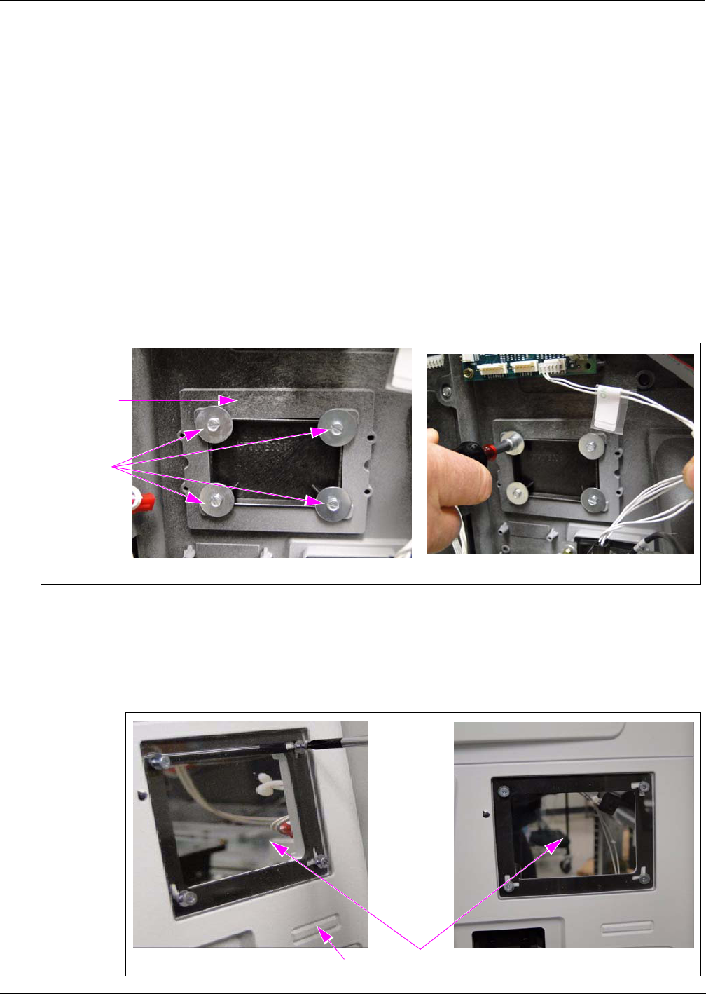
2Remove the existing Contactless Blanking Plate from the door, by removing the four screws
as shown in Figure 1.
Figure 1: Removing the Existing Contactless Blanking Plate
Contactless
Blanking Plate
Screws
(i) (ii)
3Install the Clear Lens (M07698B001) on the Bezel using the four screws (M00419B311)
provided in the kit as shown in Figure 2.
Figure 2: Installing the Clear Lens
Lens
E-CIM Bezel
(i) (ii)
Mounting the FlexPay Contactless Module on Encore S Enhanced Dispenser Equipped with SPOT EMV CRIND
Preliminary
Page 8 MDE-4939 FlexPay™ Contactless Module Installation and Service Manual · May 2011
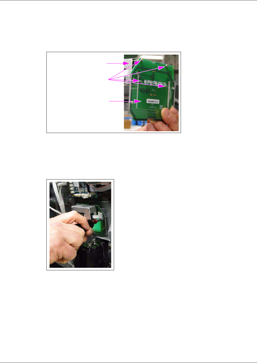
4Assemble the Bracket and the FlexPay Contactless Module using the four screws, four Nylon
Washers, and the four nuts provided in the kit (see Figure 3).
Figure 3: Bracket and the FlexPay Contactless Module Assembly
Bracket
Screws
FlexPay Contactless Module
5Mount the Bracket and the FlexPay Contactless Module Assembly onto the E-CIM Bezel
using the four screws provided in the kit (see Figure 4).
Figure 4: Mounting the Bracket and the FlexPay Contactless Module Assembly
6Connect the SPOT Contactless Cable to the FlexPay Contactless Module [see Figure 5 (i)].
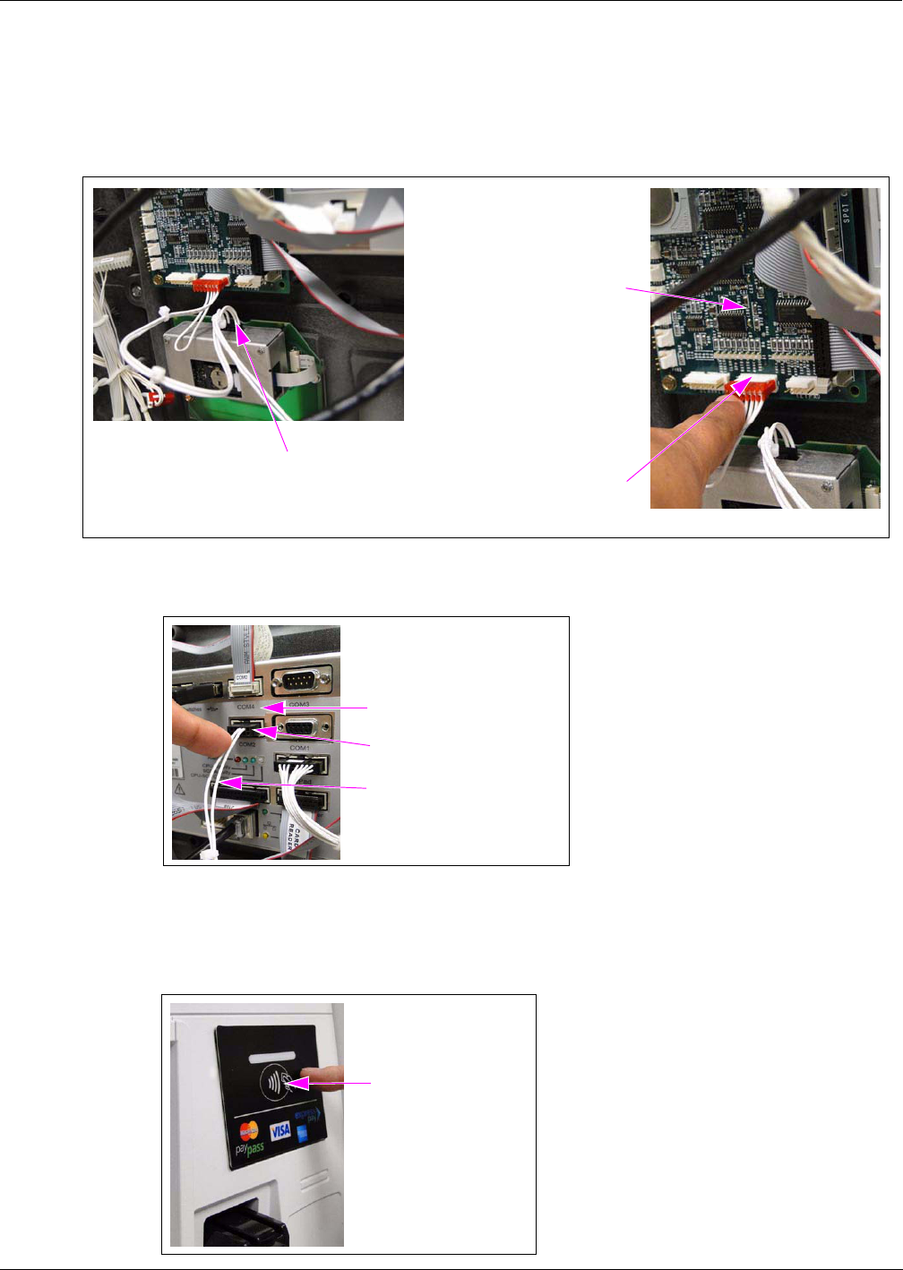
MDE-4939 FlexPay™ Contactless Module Installation and Service Manual · May 2011 Page 9
Mounting the FlexPay Contactless Module on Encore S Enhanced Dispenser Equipped with SPOT EMV CRIND
Preliminary
7Connect the SPOT Contactless Cable to the P201 port on the M07793A001 SPOT Printed
Circuit Board (PCB) as shown in Figure 5 (ii) and to the COM2 port on the SPOT EMV
CRIND display as shown in Figure 6.
Figure 5: Connecting the SPOT Contactless Cable
<<Dave Rowe’s comment: “Isn’t this called the “SIP” Board?”. Please clarify.>>
SPOT PCB (M07793A001)
(ii)
(i)
SPOT Contactless Cable
Connected to P201 Port
SPOT Contactless Cable Connected to
FlexPay Contactless Module
Figure 6: Connecting the SPOT Contactless Cable to COM2 Port
COM2 Port
SPOT Contactless Cable
SPOT EMV CRIND Display
8Fix the Contactless Graphic onto the Clear Lens on the Bezel as shown in Figure 7.
Figure 7: Fixing the Contactless Graphic
Contactless Graphic
Mounting the FlexPay Contactless Module on The Advantage Series Dispensers
Preliminary
Page 10 MDE-4939 FlexPay™ Contactless Module Installation and Service Manual · May 2011
Mounting the FlexPay Contactless Module on The
Advantage Series Dispensers
<<Please provide the part number for the parts used in this procedure.>>
To mount the FlexPay Contactless Module on The Advantage Series Dispensers, proceed as
follows:
1Remove the existing Contactless Reader, if present.
2Assemble the Bracket and the OTI Module using the four screws, the four nylon washers, and
the four nuts provided in the kit as shown in Figure 8.
Figure 8: Bracket and OTI Module Assembly
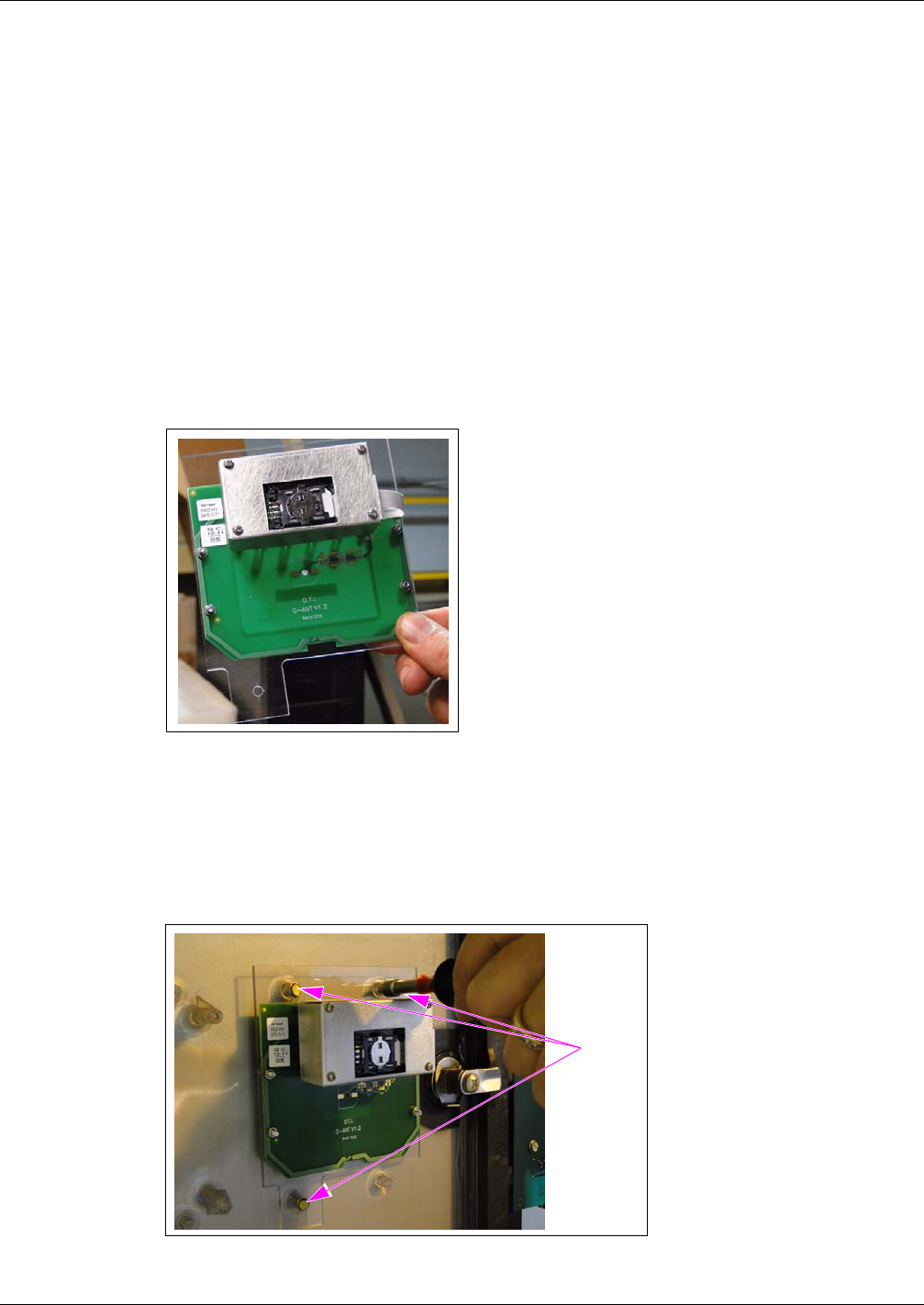
3Mount the assembled bracket and the OTI Module on the dispenser using the three screws
provided in the kit as shown in Figure 9.
Figure 9: Mounting the Assembled Bracket on the Dispenser
<<Dave Rowe’s comment: “Is there a spot on the door already for this? I really can’t tell how
this attaches to the dispenser door.”. Please clarify.>>
Screws
MDE-4939 FlexPay™ Contactless Module Installation and Service Manual · May 2011 Page 11
Mounting the FlexPay Contactless Module on Encore 300 and Encore 500 Dispensers
Preliminary
Mounting the FlexPay Contactless Module on Encore 300
and Encore 500 Dispensers
<<Please provide the part numbers for the parts used in this procedure.>>
To mount the FlexPay Contactless Module on Encore 300 and Encore 500 Dispensers, proceed
as follows:
1Remove the existing Contactless Reader, if present.
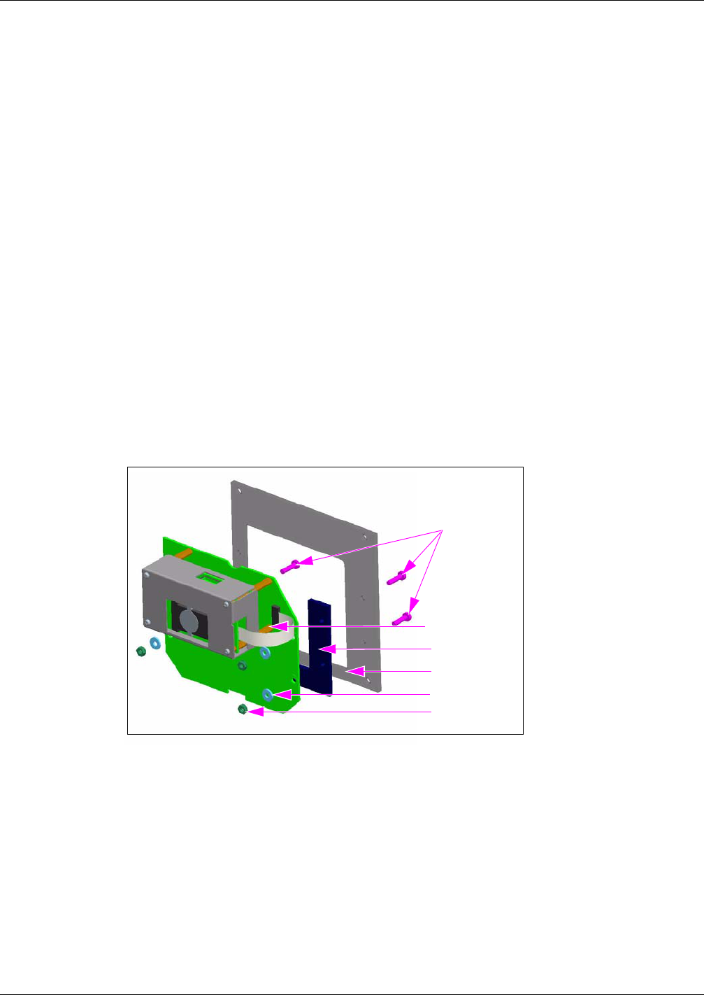
2Assemble the Bracket, the Spacer, and the OTI Module using the four screws, the four nylon
washers, and the four nuts provided in the kit (see Figure 10).
Figure 10: Bracket and OTI Module Assembly
OTI Module
Spacer
Bracket
Screws (4X)
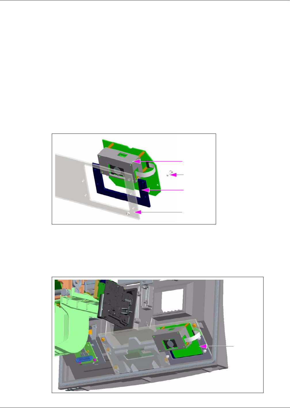
3Mount the assembled bracket, the Spacer, and the OTI Module on the dispenser using the
screws provided in the kit (see Figure 11).
Figure 11: Mounting the Assembled Bracket on the Dispenser
Assembled
Bracket
Mounting the Contactless OTI Module on Encore 300 (Pre-EMV) Dispensers
Preliminary
Page 12 MDE-4939 FlexPay™ Contactless Module Installation and Service Manual · May 2011
Mounting the Contactless OTI Module on Encore 300
(Pre-EMV) Dispensers
<<Please provide the required information.>>
Mounting the FlexPay Contactless Module on Encore 500 S
Dispensers
<<Please provide the part numbers for the parts used in this procedure.>>
To mount the FlexPay Contactless Module on Encore 500 S Dispensers, proceed as follows:
1Remove the existing Contactless Reader, if present.
2Assemble the Bracket, the Spacer, and the OTI Module using the four screws, the four nylon
washers, and the four nuts provided in the kit (see Figure 12).
Figure 12: Bracket and OTI Module Assembly
OTI Module
Spacer
Bracket
Washer
Nut
Screws (4X)
MDE-4939 FlexPay™ Contactless Module Installation and Service Manual · May 2011 Page 13
Mounting the FlexPay Contactless Module on Eclipse Dispensers
Preliminary
3Mount the assembled bracket, the Spacer, and the OTI Module on the dispenser using the three
screws provided in the kit (see Figure 13).
Figure 13: Mounting the Assembled Bracket on the Dispenser
Screws
Mounting the FlexPay Contactless Module on Eclipse
Dispensers
<<Please provide the part numbers for the parts used in this procedure.>>
To mount the FlexPay Contactless Module on Eclipse Dispensers, proceed as follows:
1Remove the existing Contactless Reader, if present.
2Assemble the Bracket and the OTI Module using the four screws, the four nylon washers, and
the four nuts provided in the kit (see Figure 14).
Figure 14: Bracket and OTI Module Assembly
Bracket
Nut
OTI Module
Screws (4X)
Mounting the FlexPay Contactless Module on FlexPay OPT Dispensers
Preliminary
Page 14 MDE-4939 FlexPay™ Contactless Module Installation and Service Manual · May 2011
3Mount the assembled bracket and the OTI Module on the dispenser using the three screws
provided in the kit (see Figure 15).
Figure 15: Mounting the Assembled Bracket on the Dispenser
Assembled
Bracket
Mounting the FlexPay Contactless Module on FlexPay OPT
Dispensers
<<Please provide the required information.>>
Installing the Contactless Interface Board on SCR 2
To install the Contactless Card Communication option on the M10728B001 or the
M10728B002 SCR2 Assembly, proceed as follows:
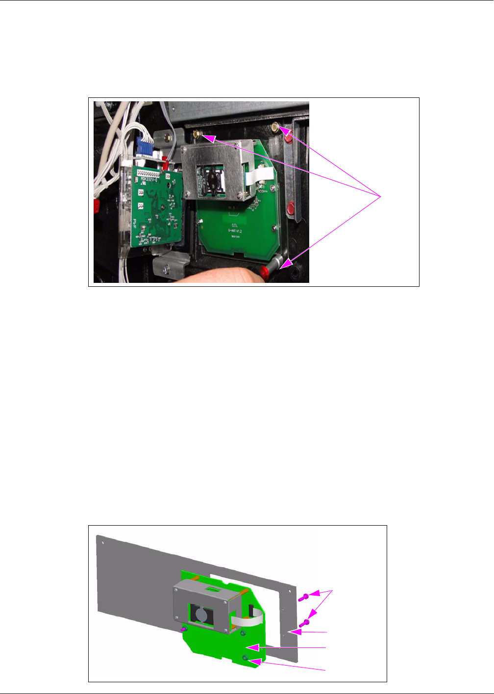
1Use a Phillips screwdriver (size 1) and remove the screw that secures the Hex standoff to the
upper flange of the SCR (see Figure 16).
Figure 16: Removing the Screw from the Hex Standoff
MDE-4939 FlexPay™ Contactless Module Installation and Service Manual · May 2011 Page 15
Installing the Contactless Interface Board on SCR 2
Preliminary
2Install the Upper Mounting Bracket and the new screw provided in the kit for the Contactless
Communication PCB (see Figure 17).
Figure 17: Installing the Upper Mounting Bracket
Upper Mounting Bracket
(i) (ii)
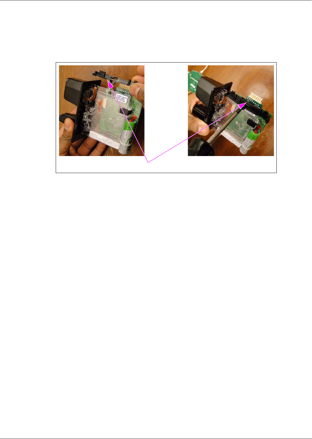
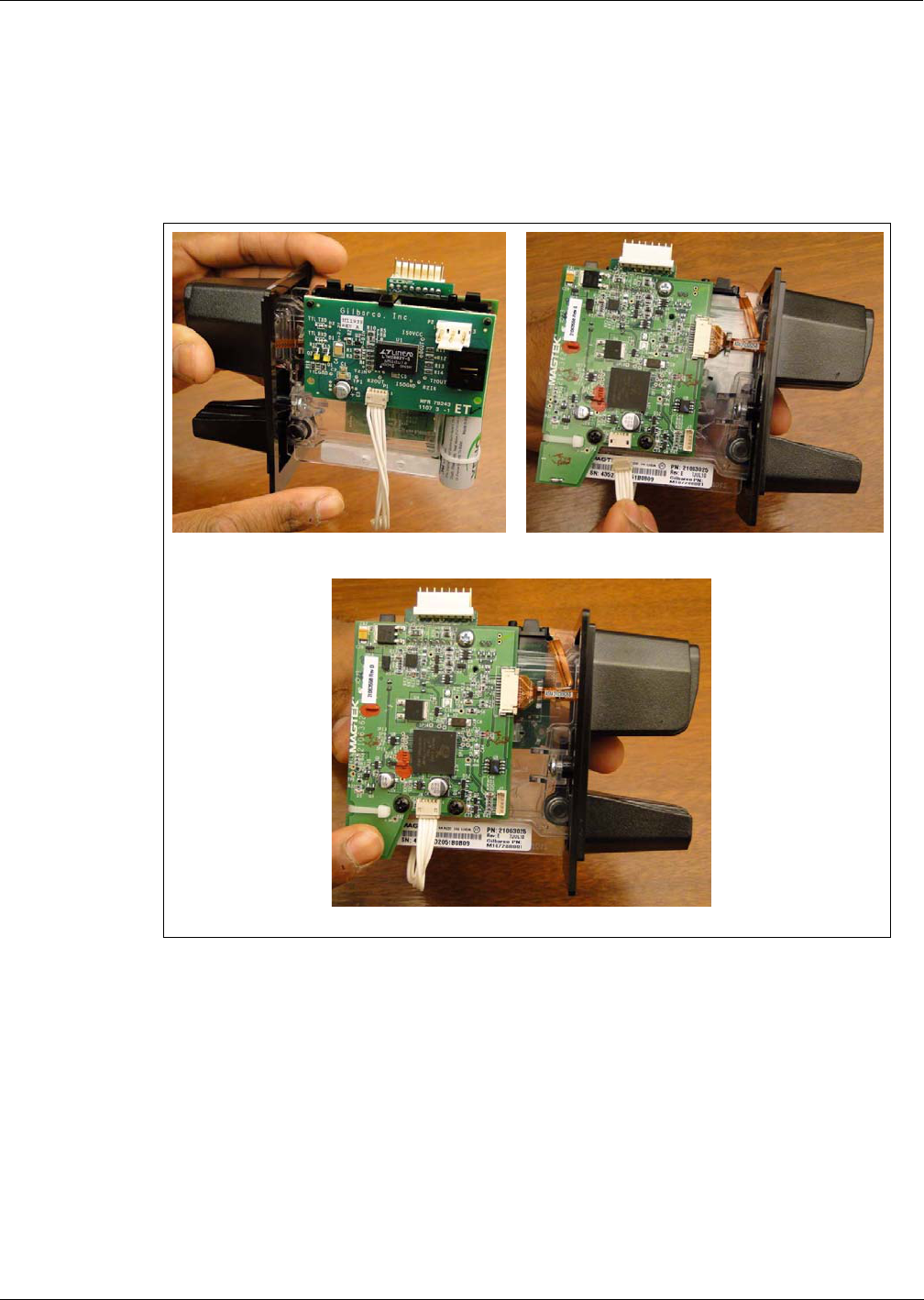
3Install the Contactless Interface PCB (M11242B002) as follows:
a Align the holes on the top edge of the PCB to the two pins on the Upper Mounting Bracket
and press the PCB in until the Upper Mounting Bracket snaps and holds the PCB in place as
shown in Figure 18 on page 16 and Figure 19 on page 17.
b Install the screw provided in the kit through the forward lower mounting hole
as shown in Figure 18 on page 16. <<Please clarify if this step is required.>>
Installing the Contactless Interface Board on SCR 2
Preliminary
Page 16 MDE-4939 FlexPay™ Contactless Module Installation and Service Manual · May 2011
Figure 18: Installing the Contactless Interface PCB
(i) (ii)
(iii)
Pins on the Upper
Mounting Bracket
<<Please validate.>>
MDE-4939 FlexPay™ Contactless Module Installation and Service Manual · May 2011 Page 17
Installing the Contactless Interface Board on SCR 2
Preliminary
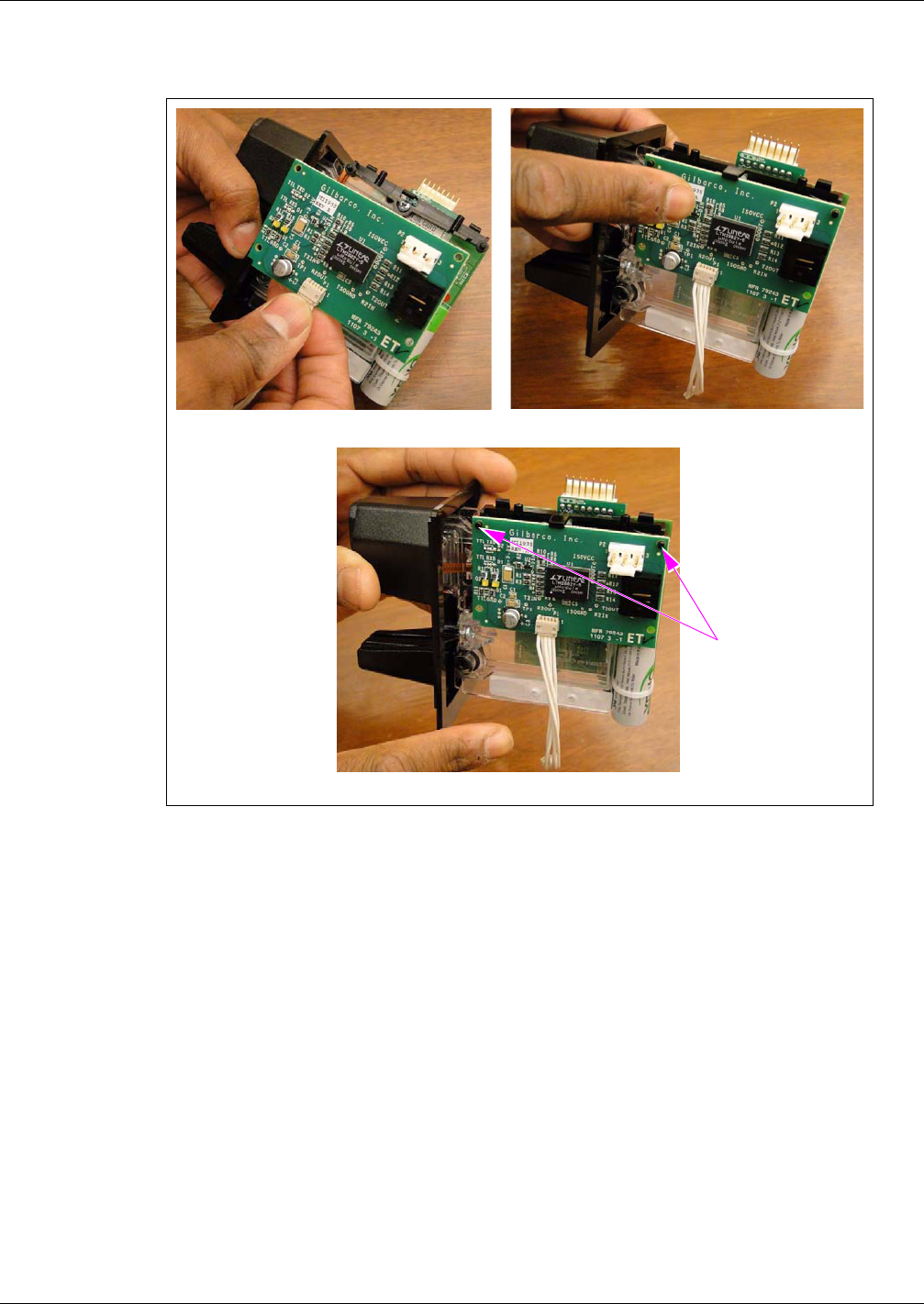
4Connect the Contactless Interface PCB Interconnect Cable to the Card Reader as shown in
Figure 19.
Note: Both the ends of the Contactless Communication PCB Interconnect Cable have the
same connector, so either end may be used.
Figure 19: Connecting the Contactless Interface PCB Interconnect Cable
(i) (ii)
(iii)
Installing the Contactless Interface Board on SCR 2
Preliminary
Page 18 MDE-4939 FlexPay™ Contactless Module Installation and Service Manual · May 2011
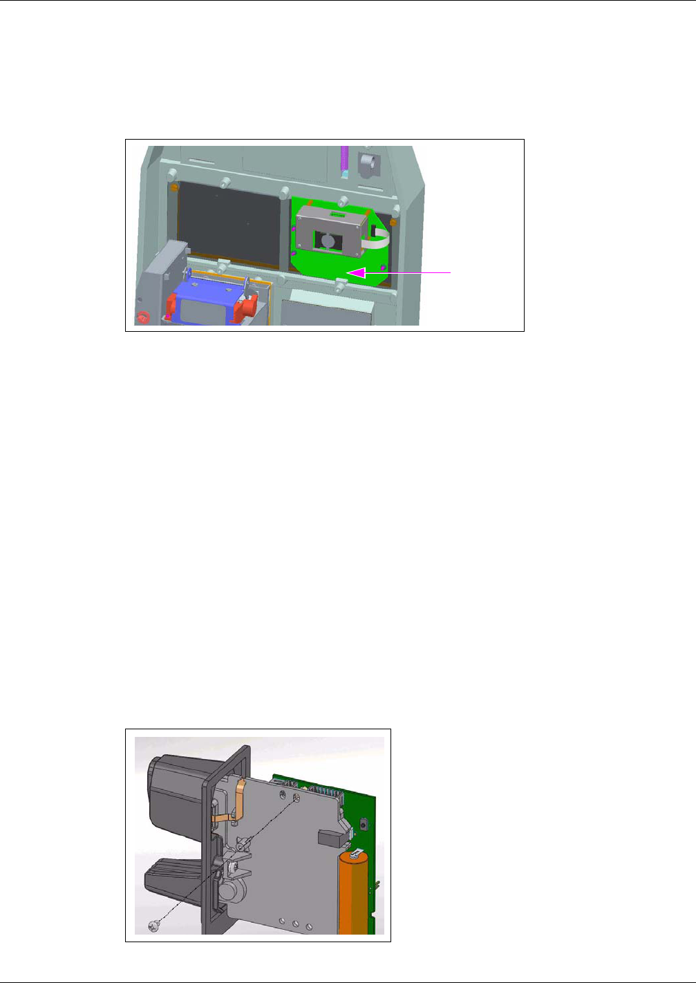
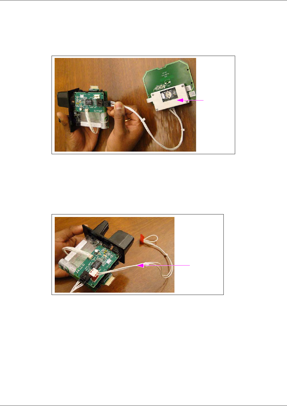
Connecting the OTI Module to the Contactless Interface Board
Connect the OTI Module to the Contactless Interface Board as shown in Figure 20.
Figure 20: Connecting the OTI Module
OTI Module
Connecting Power to the Contactless Communication Board
Connect the Power Cable to the Contactless Communication Board as shown in Figure 21.
Figure 21: Connecting Power Cable to the Contactless Communication Board
Power Cable

MDE-4939 FlexPay™ Contactless Module Installation and Service Manual · May 2011 Page 19
Configuring SPOT EMV CRIND for FlexPay Contactless Module
Preliminary
Configuring SPOT EMV CRIND for FlexPay Contactless
Module
To configure the SPOT EMV CRIND for FlexPay Contactless Module, proceed as follows:
1Power-up the SPOT EMV CRIND. A white screen with the Gilbarco® logo and software
package version is displayed momentarily (see Figure 22).
Figure 22: Software Packages Screen
<1> enter setup appears at start-up and also when the
FlexPay Card Reader requires activation.
2Press 1. The Service Menu screen is displayed as shown in Figure 23.
Figure 23: Service Menu - Screen 1

Configuring SPOT EMV CRIND for FlexPay Contactless Module
Preliminary
Page 20 MDE-4939 FlexPay™ Contactless Module Installation and Service Manual · May 2011
3Enter the right-most six digits of the PPN and press ENTER/OK. The Service Menu - Main
Menu is displayed (see Figure 24).
Note: If you do not enter the password within 60 seconds, the unit automatically restarts.
Figure 24: Service Menu - Main Menu
4Press 3. The System Configuration Menu is displayed as shown in Figure 26.
Figure 25: System Configuration Menu

MDE-4939 FlexPay™ Contactless Module Installation and Service Manual · May 2011 Page 21
Configuring SPOT EMV CRIND for FlexPay Contactless Module
Preliminary
5Press 2 to change Contactless Card Reader to OTI (see Figure 26).
Figure 26: System Configuration Menu - Contactless Card Reader Select
6Press OK to save the changes and exit. The display goes back to the Service Menu
(see Figure 27).
Figure 27: Service Menu
7Press Cancel. The SPOT EMV CRIND restarts.
Verifying Functionality of FlexPay Contactless Module Through CRIND Diagnostics (Generic CRIND)
Preliminary
Page 22 MDE-4939 FlexPay™ Contactless Module Installation and Service Manual · May 2011
Verifying Functionality of FlexPay Contactless Module
Through CRIND Diagnostics (Generic CRIND)
As an additional security measure, the FlexPay CRIND Keypad requires that the Enter
key be pressed after any number entry (in Diagnostic Mode only).
IMPORTANT INFORMATION
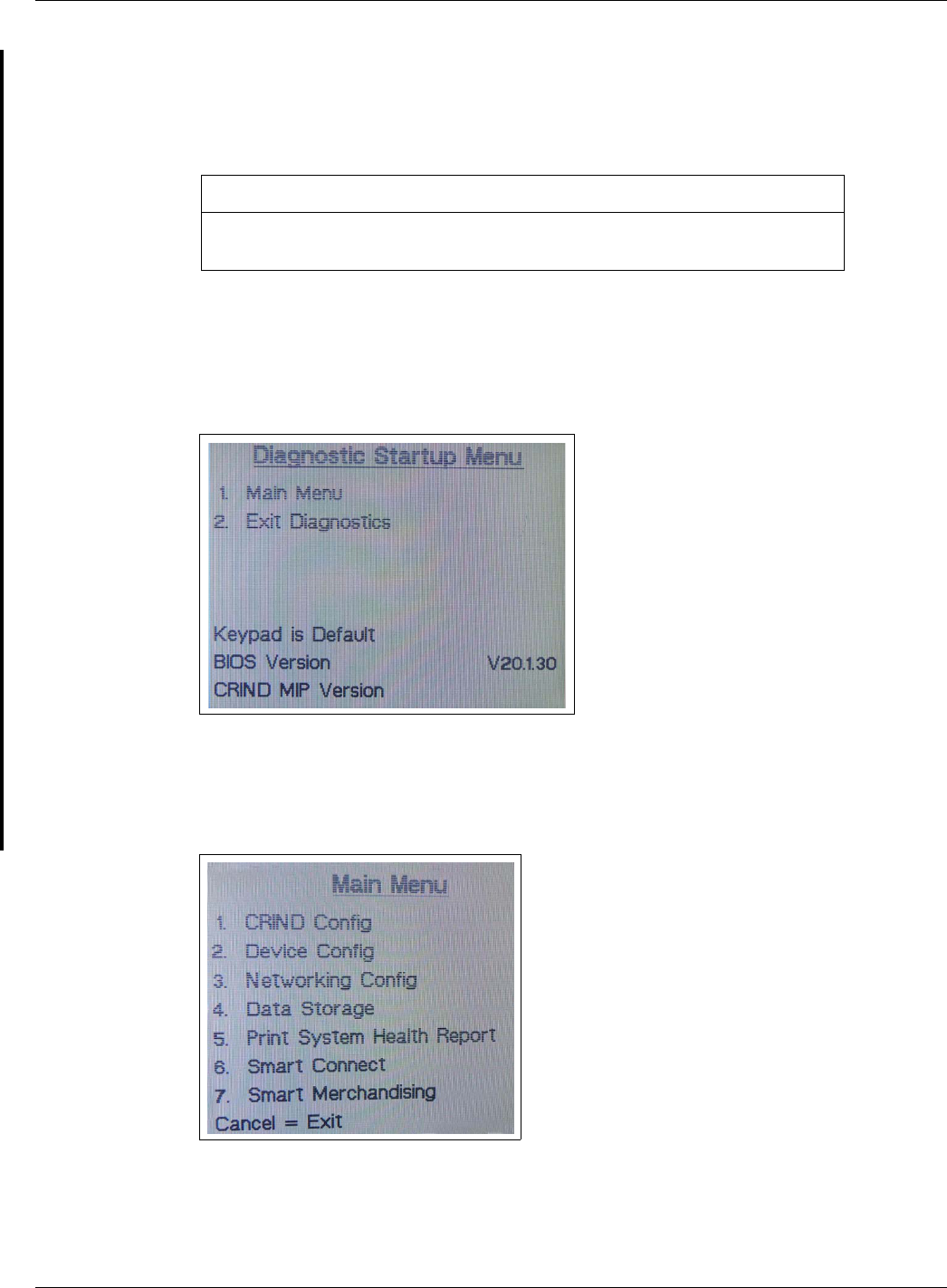
1Enter CRIND Diagnostics by swiping the CRIND Diagnostics Card into the Card Reader. The
CRIND Diagnostics Startup Menu is displayed (see Figure 28).
Figure 28: CRIND Diagnostics - Startup Menu
2Press 1 > Enter. The Main Menu is displayed (see Figure 29).
Figure 29: CRIND Diagnostics - Main Menu
MDE-4939 FlexPay™ Contactless Module Installation and Service Manual · May 2011 Page 23
Verifying Functionality of FlexPay Contactless Module Through CRIND Diagnostics (Generic CRIND)
Preliminary
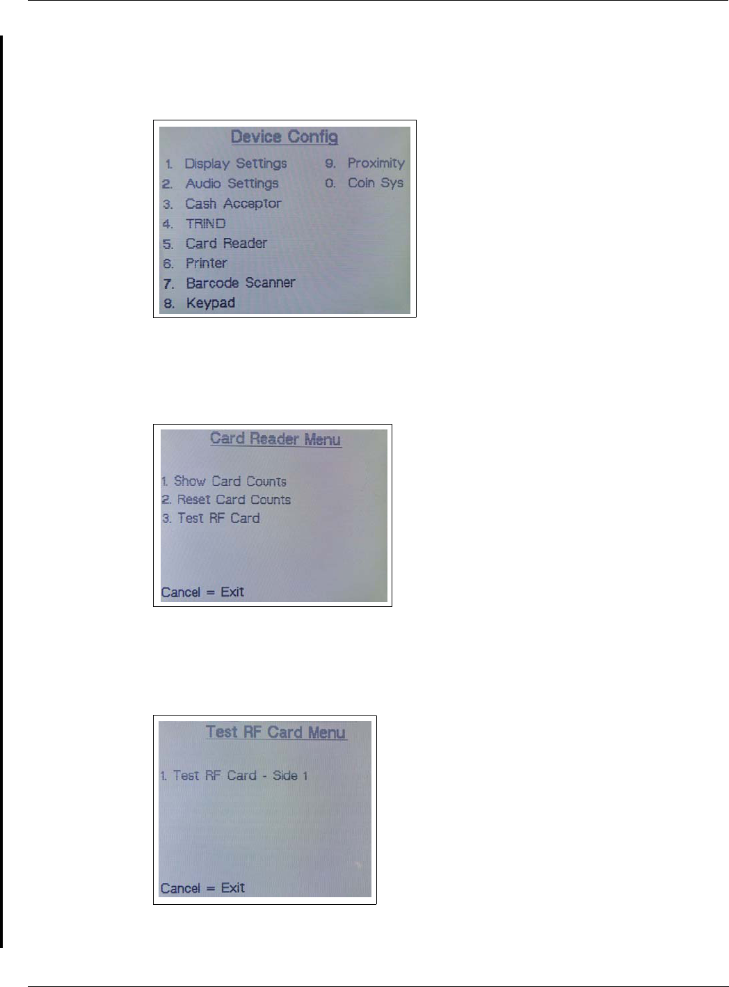
3Press 2 > Enter. The Device Config menu is displayed (see Figure 30).
Figure 30: CRIND Diagnostics - Device Config Menu
4Press 5 > Enter. The Card Reader Menu is displayed (see Figure 31).
Figure 31: CRIND Diagnostics - Card Reader Menu
5Press 3 > Enter. The Test RF Card Menu is displayed (see Figure 32).
Figure 32: CRIND Diagnostics - Test RF Card Menu
Note: Depending on the side on which the CRIND Diagnostics is performed, Side 1 or Side 2
is displayed.
Verifying Functionality of FlexPay Contactless Module Through CRIND Diagnostics (Generic CRIND)
Preliminary
Page 24 MDE-4939 FlexPay™ Contactless Module Installation and Service Manual · May 2011
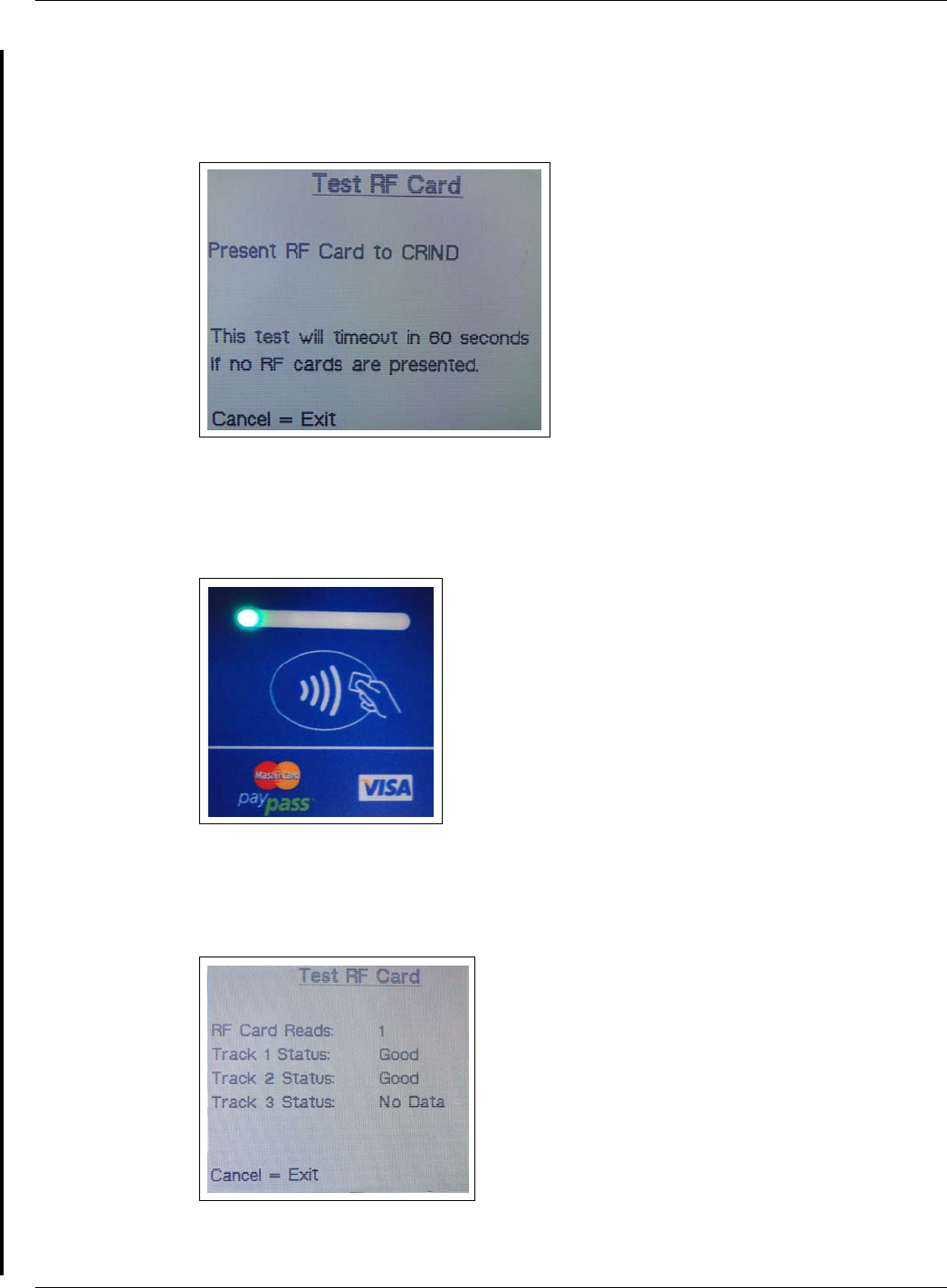
6Press 1 > Enter. The Test RF Card screen is displayed (see Figure 33).
Figure 33: CRIND Diagnostics - Test RF Card Screen
7Present the RF card as shown in Figure 34.
Figure 34: Presenting the RF Card
If a valid read is made, Figure 35 is displayed.
Figure 35: CRIND Diagnostics - Successful Test RF Card Screen
If a valid read is not made, verify cable connections and power connections. Check LED
indicators for power connection, proper functioning, and so on.
MDE-4939 FlexPay™ Contactless Module Installation and Service Manual · May 2011 Page 25
Affixing FlexPay Contactless FCC Label
Preliminary
Affixing FlexPay Contactless FCC Label
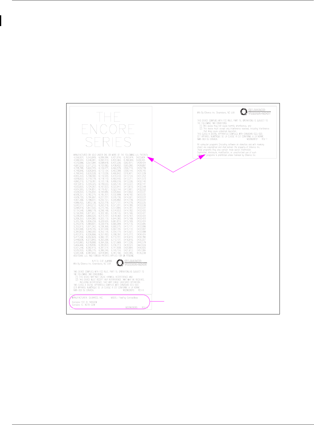
Affixing the M02962B015 FlexPay Contactless FCC Label on the Dispenser
Inner Sheathing
Obtain the FlexPay Contactless FCC Label (M02962B015) from the kit and install it under the
patent label as shown in Figure 36.
Figure 36: Affixing the M02962B015 FlexPay Contactless FCC Label
~OR~
Patent Label
Note: Depending on the year of manufacture
of the dispenser, the patent label may
be either M02962B010 or
M02962B101.
FlexPay Contactless FCC Label
(M02962B015)
<<Please validate.>>

© 2011 Gilbarco Inc.
7300 West Friendly Avenue · Post Office Box 22087
Greensboro, North Carolina 27420
Phone (336) 547-5000 · http://www.gilbarco.com · Printed in the U.S.A.
MDE-4939 FlexPay™ Contactless Module Installation and Service Manual · May 2011
CRIND®, Eclipse®, Encore®, Gilbarco®, The Advantage® Series, and TRIND® are registered trademarks of Gilbarco Inc. FlexPay™ is a
trademark of Gilbarco Inc. MasterCard® is a registered trademark of MasterCard International Inc. Phillips® is a registered trademark of
The Phillips Screw Co. UL® is a registered trademark of Underwriters’ Laboratories Inc. Visa® is a registered trademark of Visa Inc.
Preliminary