Gilbarco LFMAT Mat Reader User Manual 13 0278 Exhibit Cover
Gilbarco Inc. Mat Reader 13 0278 Exhibit Cover
UserManual.wiki
>
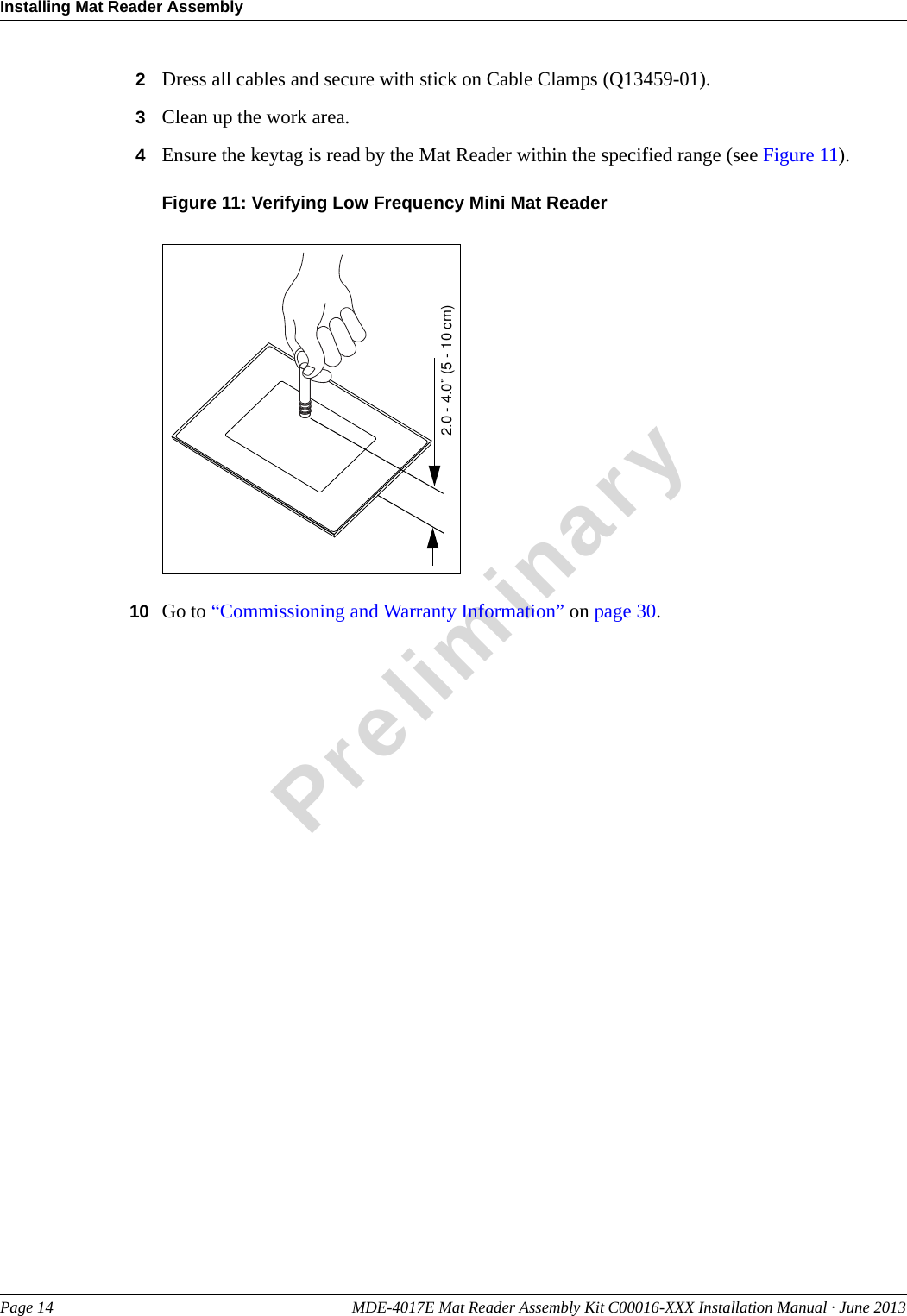
Gilbarco
>
LFMAT User Manual
Manual
Navigation menu
Upload a User Manual
Namespaces
Wiki Guide
HTML
PDF
Info
Views
User Manual
Discussion / Help
Navigation
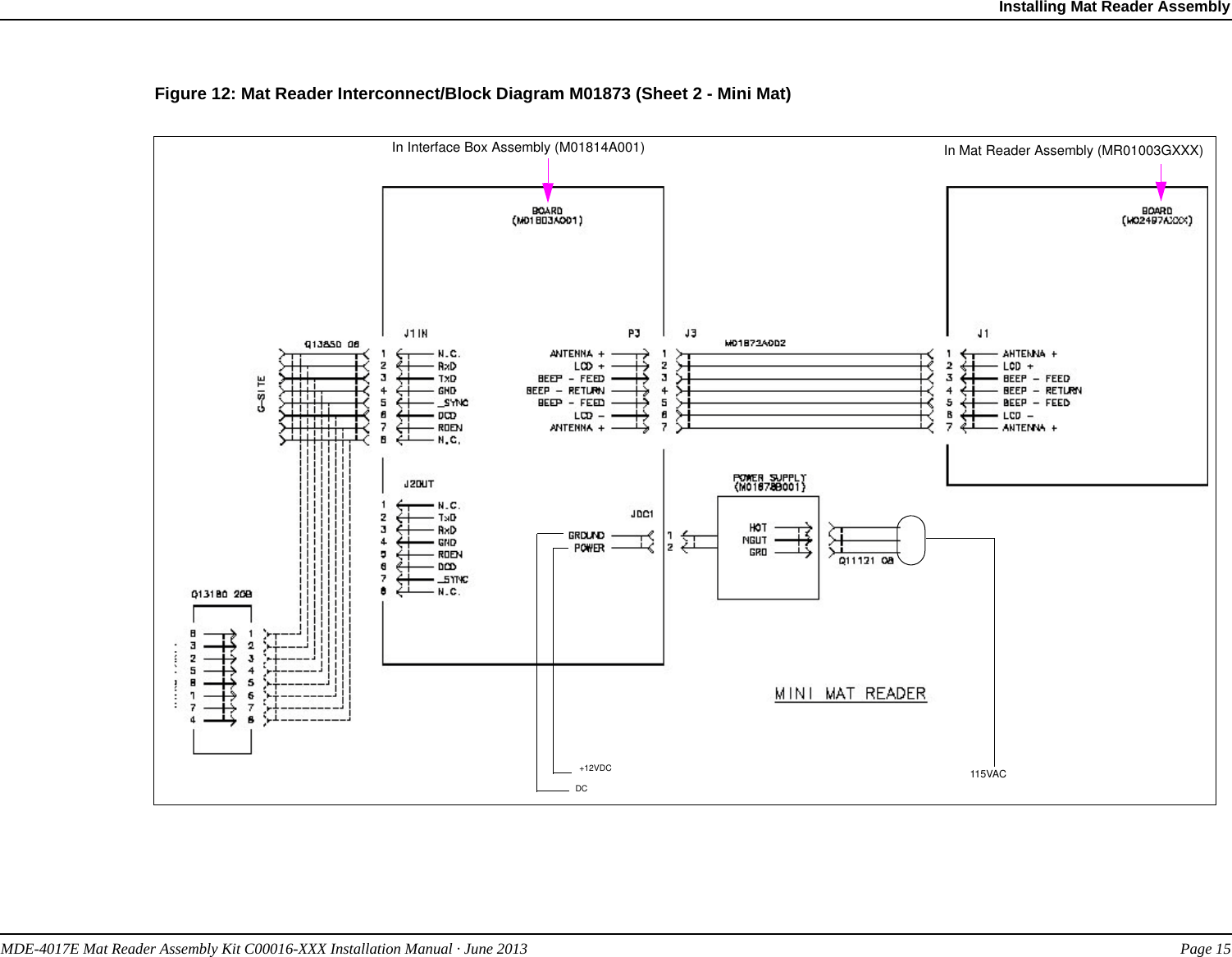
![MDE-4017E Mat Reader Assembly Kit C00016-XXX Installation Manual · June 2013 Page 3IntroductionPreliminaryFollowing table lists the parts included in the C00016-011 Kit - Low Frequency [Personal Identification Number (PIN) Pad]:Description Part Number QuantityAssembly, Interface Box, Mat Reader M01814A001 1Cable, Mat Reader Drive 6 feet (1.8 m) M01872A002 1Ferrite, Snap-on Q11433-107 1Ferrite, Clip-on Q11433-110 2Power Supply, Wall-mount M01878B001 1Jack, Jump Q11011-01 1Clamp, Flat Cable, Stick On, Small Q13459-01 1Cable, Data, CAT-5, 6 feet (1.8 m) Q13850-06 1Label, Pressure Sensitive N23290-02 1Screw, Thread Forming, 8-32 X 3/8” K85736-06 2Adapter Plate, PIN Pad M03182B001 1Cable-tie Q10178-01 3Nut, Clinch, 4-40 Q10227-06 3Screw, Machine, Pan Head, Phillips 4-40 X 1/2” Q11270-21 3Screw, Machine, Pan Head, Phillips 6-32 X 5/8” Q11270-38 3Bumper, Rubber, Hemisphere, Adhesive-backed, (Black) Q12226-01 4Gender Mender, Modular Jack To 9-pin D-subminiature, (Black) Q13180-20B 1Notes: 1) The PIN Pad and Pedestal are not included with this kit.2) For component additions to this kit, refer to “Additions to Mat Reader Kits”.Additions to Mat Reader KitsFollowing table lists the parts required in addition to the C00016-XXX Kit:Description Part Number (see Note) Applicable Kit(s) QuantityMat Reader, Mini MR01003GXXX C00016-010 1Mat Reader, PIN Pad MR02001GXXX C00016-011 1Note: XXX is the graphic-specific identifier.Related DocumentsDocument Number Title GOLD LibraryMDE-3620 POS Site Preparation Manual Site PrepMDE-3816 Passport Hardware Start-up & Service Manual • Passport• Service ManualMDE-4157 Passport Combined WS Installation Poster PassportMDE-4158 Passport Cashier WS Installation Poster PassportMDE-4159 Passport Manager WS Installation Poster Passport20](https://usermanual.wiki/Gilbarco/LFMAT/User-Guide-2041626-Page-4.png)

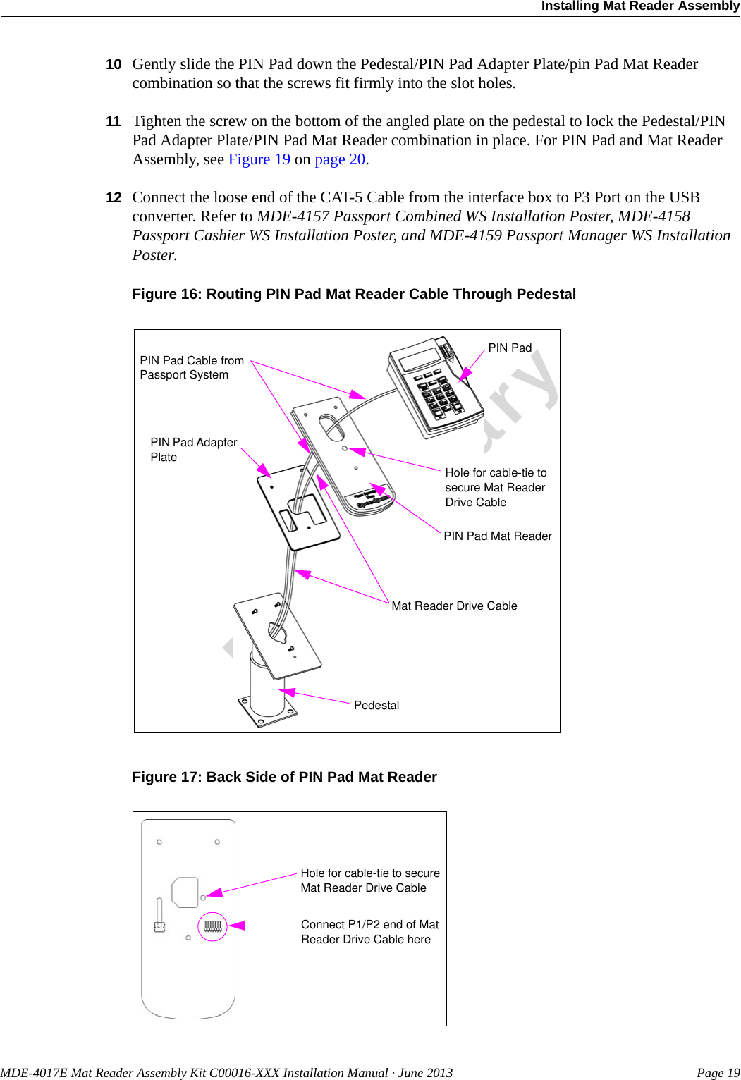
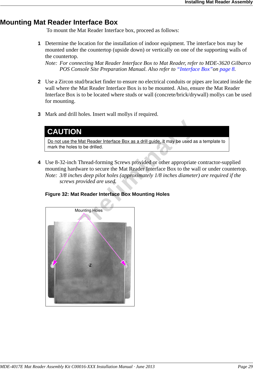
![Installing Mat Reader AssemblyPage 20 MDE-4017E Mat Reader Assembly Kit C00016-XXX Installation Manual · June 2013PreliminaryFigure 18: Screw Head Height Above PIN Pad Mat ReaderPIN Pad Mat ReaderPIN Pad Adapter PlateScrew0.160”(4 mm)Pedestal TopFigure 19: PIN Pad Mat Reader Assembly on PedestalPIN Pad Mat Reader - With Pedestal and Without Hole in CountertopNote: The pedestal will serve as support for the PIN Pad and Mat Reader. The PIN Pad Cable (supplied with PIN Pad) and Mat Reader Drive Cable (M01872A002) will be routed between the Mat Reader and PIN Pad, and secured to the outside of the pedestal.1If not already installed, use three screws to mount the PIN Pad pedestal to the countertop.2Route the Mat Reader Drive Cable from the interface box beside the pedestal and through the hole in the top of the PIN Pad Adapter Plate [M03182B001 (see Figure 20 on page 21)].3Carefully connect the P1/P2 Connector of the Mat Reader Drive Cable to the connector on the back of the PIN Pad Mat Reader (see Figure 17 on page 19).4Route Cable-tie (Q10178-01) through designated hole in PIN Pad Mat Reader (see Figure 20 on page 19) and around Mat Reader Drive Cable and pull cable-tie end through its locking slot. This provides strain relief for the cable.5Route the PIN Pad Cable from the Passport System beside the pedestal across the top of the PIN Pad Mat Reader (see Figure 20 on page 21).6Carefully connect the connector on the PIN Pad Cable to the connector on the back of the PIN Pad.](https://usermanual.wiki/Gilbarco/LFMAT/User-Guide-2041626-Page-21.png)
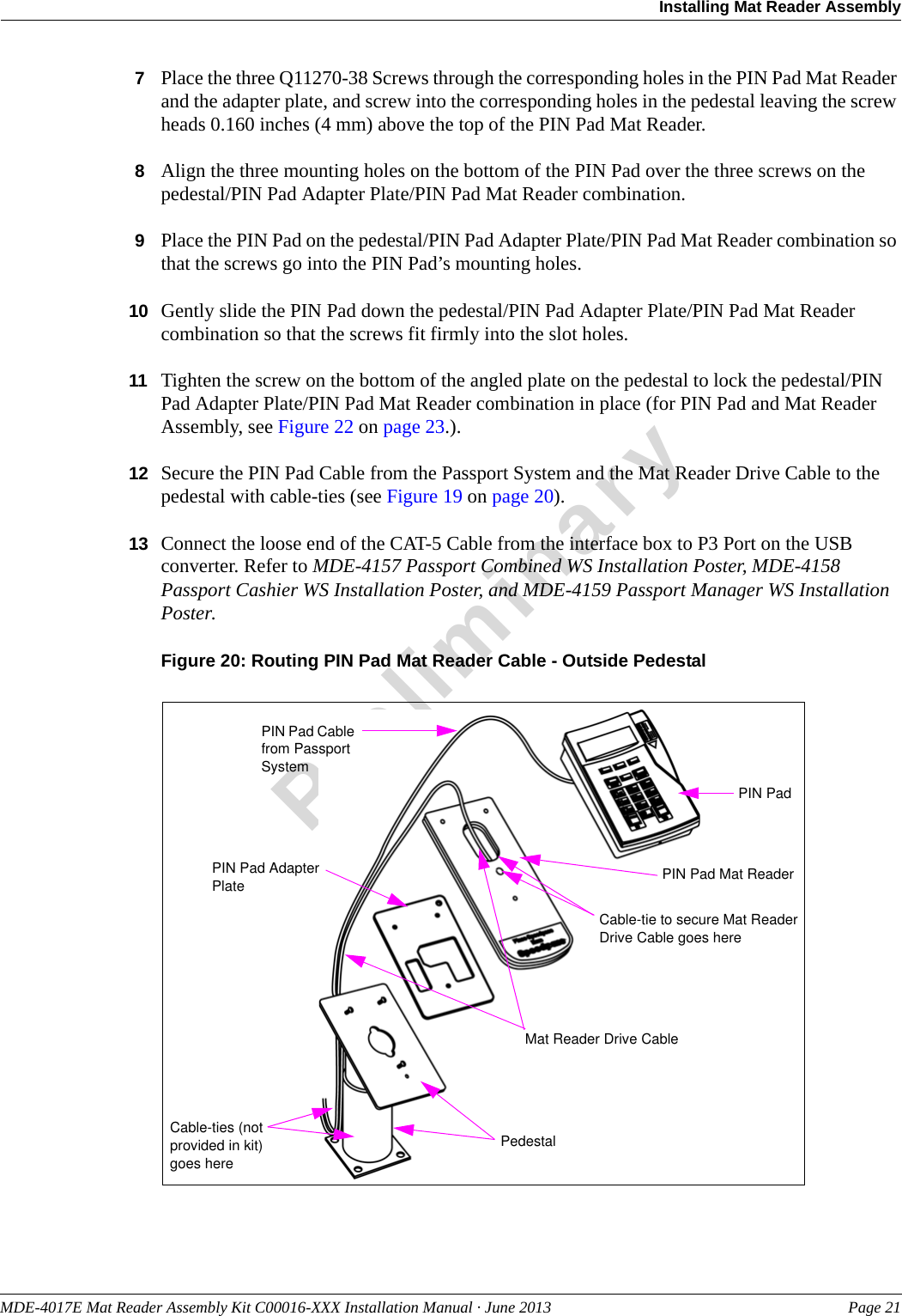
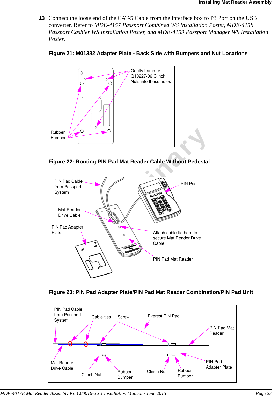
![Installing Mat Reader AssemblyPage 22 MDE-4017E Mat Reader Assembly Kit C00016-XXX Installation Manual · June 2013PreliminaryPIN Pad Mat Reader - Without Pedestal and Hole in CountertopTo install the PIN Pad Mat Reader without pedestal and hole in countertop, proceed as follows:Note: The PIN Pad Cable (supplied with PIN Pad) and Mat Reader Drive Cable ((M01872A002) are routed between the Mat Reader and PIN Pad. The four Rubber Bumpers (Q12226-01) are attached to the back of the PIN Pad Adapter Plate (M03182B001) to keep it off the countertop.1Place the PIN Pad Adapter Plate face down on a clean, shock absorbing material (such as corrugated cardboard or thick shop rag); then firmly hammer the three Q10227-06 Clinch Nuts into the three holes in the back side of the PIN Pad Adapter Plate (see Figure 21 on page 23).2Attach the four adhesive-backed Rubber Bumpers to the back side of the PIN Pad Adapter Plate in the four corners (see Figure 28 on page 25).3Route the Mat Reader Drive Cable from the interface box down through the D-shaped hole in the PIN Pad Mat Reader [M02001GXXX (see Figure 22 on page 23)].4Carefully connect the P1/P2 connector of the Mat Reader Drive Cable to the connector on the back of the PIN Pad Mat Reader (see Figure 17 on page 19).5Route Cable-tie (Q10178-01) through designated hole in PIN Pad Mat Reader (see Figure 22 on page 23 and Figure 17 on page 19) and around Mat Reader Drive Cable and pull cable-tie end through its locking slot. The cable-tie provides strain relief for the cable.6Route the PIN Pad Cable from the Passport System directly out of the back of the PIN Pad (see Figure 22 on page 23).7Carefully connect the connector on the PIN Pad Cable to the connector on the back of the PIN Pad.8Place the three Q11270-21 Screws through the screw holes in the PIN Pad Mat Reader into the front of the PIN Pad Adapter Plate; and screw into the clinch nuts in the PIN Pad Adapter Plate leaving the screw heads 0.160 inches (4 mm) above the top of the PIN Pad Mat Reader.9Align the three mounting holes on the bottom of the PIN Pad over the three screws on the PIN Pad Adapter Plate/PIN Pad Mat Reader combination.10 Place the PIN Pad on the PIN Pad Adapter Plate/PIN Pad Mat Reader combination so that the screws go into the PIN Pad’s mounting holes.11 Gently slide the PIN Pad down the PIN Pad Adapter Plate/PIN Pad Mat Reader combination so that the screws fit firmly into the slot holes to form the PIN Pad Adapter Plate/PIN Pad Mat Reader/PIN Pad unit (see Figure 23 on page 23).12 Use remaining cable-ties to secure Mat Reader and PIN Pad Cables together for neat appearance on countertop (see Figure 23 on page 23).](https://usermanual.wiki/Gilbarco/LFMAT/User-Guide-2041626-Page-23.png)