Gilbarco LFMAT Mat Reader User Manual 13 0278 Exhibit Cover
Gilbarco Inc. Mat Reader 13 0278 Exhibit Cover
Gilbarco >
Manual

5015 B.U. Bowman Drive Buford, GA 30518 USA Voice: 770-831-8048 Fax: 770-831-8598
Certification Exhibit
FCC ID: N6SLFMAT
IC: 827B-LFMAT
FCC Rule Part: 15.209
IC Radio Standards Specification: RSS-210
ACS Project Number: 13-0278
Manufacturer: Gilbarco Inc.
Models: C00016-011, C00016-010
Manual

MDE-4017E Mat Reader Assembly Kit C00016-XXX Installation Manual · June 2013 Page 1
Preliminary
06/05/13
Introduction
Purpose This manual provides instructions for installing the Mat Reader Assembly Kit C00016-XXX
on the Passport System. The Mat Reader allows customers to automatically authorize sales
using a hand-held transponder tag (also known as a keytag).
Table of Contents
Topic Page
Introduction 1
Important Safety Information 5
Installing Mat Reader Assembly 7
Commissioning and Warranty Information 30
Important Notice
This equipment has been tested and found to comply with the limits for a Class A digital
device pursuant to Part 15 of the Federal Communications Commission (FCC) Rules. These
limits are designed to provide reasonable protection against harmful interference when the
equipment is operated in a commercial environment. This equipment generates, uses and can
radiate radio frequency energy, and if not installed and used in accordance with the instruction
manual, may cause harmful interference to radio communications. Operation of this
equipment in a residential area is likely to cause harmful interference in which case the user
will be required to correct the interference at his own expense. Changes or modifications not
expressly approved by the manufacturer could void the user’s authority to operate this
equipment.
The long term characteristics or the possible physiological effects of radio frequency
electromagnetic fields have not been investigated by Underwriters’ Laboratories, Inc. (UL®).
Industry Canada Warning
This device complies with Industry Canada licence-exempt Radio Standards Specification
(RSS) standard(s). Operation is subject to the following two conditions:
• This device may not cause interference.
• This device must accept any interference, including interference that may cause undesired
operation of the device.
Le présent appareil est conforme aux CNR d’Industrie Canada applicables aux appareils radio
exempts de licence. L’exploitation est autorisée aux deux conditions suivantes:
• l’appareil ne doit pas produire de brouillage.
• l’utilisateur de l’appareil doit accepter tout brouillage radioélectrique subi, même si le
brouillage est susceptible d’en compromettre le fonctionnement.
MDE-4017E
Mat Reader Assembly Kit C00016-XXX
Installation Manual
June 2013

Introduction
Page 2 MDE-4017E Mat Reader Assembly Kit C00016-XXX Installation Manual · June 2013
Preliminary
Under Industry Canada regulations, this radio transmitter may only operate using an antenna
of a type and maximum (or lesser) gain approved for the transmitter by Industry Canada. To
reduce potential radio interference to other users, the antenna type and its gain should be so
chosen that the equivalent isotropically radiated power (e.i.r.p.) is not more than that necessary
for successful communication.
Conformément à la réglementation d’Industrie Canada, le présent émetteur radio peut
fonctionner avec une antenne d’un type et d’un gain maximal (ou inférieur) approuvé pour
l’émetteur par Industrie Canada. Dans le but de réduire les risques de brouillage
radioélectrique à l’intention des autres utilisateurs, il faut choisir le type d’antenne et son gain
de sorte que la puissance isotrope rayonnée équivalente (p.i.r.e.) ne dépasse pas l’intensité
nécessaire à l’établissement d’une communication satisfaisante.
Note: To ensure compliance with Electro-magnetic Compatibility (EMC) standards, do not
remove the ferrite beads from cable assemblies provided with them.
Required Tools
Following tools are required to install Mat Reader kits:
• Drill Motor and Bits
• Needle Nose Pliers
• Phillips® Screwdriver
•Zircon
® Stud/bracket Finder
Parts Lists
Following table lists the parts included in the C00016-010 Kit - Low Frequency (Mini Mat):
Description Part Number Quantity
Assembly, Interface Box, Mat Reader M01814A001 1
Tape, Neoprene Foam M02498B001 1
Cable, Mat Reader Drive 6 feet (1.8 m) M01872A002 1
Ferrite, Snap-on Q11433-107 1
Power Supply, Wall-mount M01878B001 1
Jack, Jump Q11011-01 1
Cable, Data, CAT-5, 6 feet (1.8 m) Q13850-06 1
Clamp, Flat Cable, Stick on, Small Q13459-01 3
Ferrite, Snap-on Q11433-110 <<Please
provide the
required
information.>>
Screw, Thread Forming, 8-32 X 3/8” K85736-06 2
Tape, Pressure Sensitive N23290-02 1
Note: For component additions to this kit, refer to “Additions to Mat Reader Kits” on page 3.
Qty.= 0 part not
needed
This should be 2

MDE-4017E Mat Reader Assembly Kit C00016-XXX Installation Manual · June 2013 Page 3
Introduction
Preliminary
Following table lists the parts included in the C00016-011 Kit - Low Frequency [Personal
Identification Number (PIN) Pad]:
Description Part Number Quantity
Assembly, Interface Box, Mat Reader M01814A001 1
Cable, Mat Reader Drive 6 feet (1.8 m) M01872A002 1
Ferrite, Snap-on Q11433-107 1
Ferrite, Clip-on Q11433-110 2
Power Supply, Wall-mount M01878B001 1
Jack, Jump Q11011-01 1
Clamp, Flat Cable, Stick On, Small Q13459-01 1
Cable, Data, CAT-5, 6 feet (1.8 m) Q13850-06 1
Label, Pressure Sensitive N23290-02 1
Screw, Thread Forming, 8-32 X 3/8” K85736-06 2
Adapter Plate, PIN Pad M03182B001 1
Cable-tie Q10178-01 3
Nut, Clinch, 4-40 Q10227-06 3
Screw, Machine, Pan Head, Phillips 4-40 X 1/2” Q11270-21 3
Screw, Machine, Pan Head, Phillips 6-32 X 5/8” Q11270-38 3
Bumper, Rubber, Hemisphere, Adhesive-backed, (Black) Q12226-01 4
Gender Mender, Modular Jack To 9-pin D-subminiature, (Black) Q13180-20B 1
Notes: 1) The PIN Pad and Pedestal are not included with this kit.
2) For component additions to this kit, refer to “Additions to Mat Reader Kits”.
Additions to Mat Reader Kits
Following table lists the parts required in addition to the C00016-XXX Kit:
Description Part Number (see Note) Applicable Kit(s) Quantity
Mat Reader, Mini MR01003GXXX C00016-010 1
Mat Reader, PIN Pad MR02001GXXX C00016-011 1
Note: XXX is the graphic-specific identifier.
Related Documents
Document
Number Title GOLD Library
MDE-3620 POS Site Preparation Manual Site Prep
MDE-3816 Passport Hardware Start-up & Service Manual • Passport
• Service Manual
MDE-4157 Passport Combined WS Installation Poster Passport
MDE-4158 Passport Cashier WS Installation Poster Passport
MDE-4159 Passport Manager WS Installation Poster Passport
2
0

Introduction
Page 4 MDE-4017E Mat Reader Assembly Kit C00016-XXX Installation Manual · June 2013
Preliminary
Abbreviations and Acronyms
Term Description
ASC Authorized Service Contractor
CRT Cathode Ray Tube
CWS Cashier Workstation
e.i.r.p Equivalent Isotropically Radiated Power
EMC Electro-magnetic Compatibility
FCC Federal Communications Commission
IC Integrated Circuits
MWS Manager Workstation
NEC National Electric Code
NFPA National Fire Protection Association
p.i.r.e Puissance Isotrope Rayonnée Équivalente
PCB Printed Circuit Board
PIN Personal Identification Number
POS Point of Sale
RSS Radio Standards Specification
Required Reading
Before installation, the installer must read, understand, and follow:
• This manual.
• National Fire Protection Agency (NFPA) 30A, The Automotive and Marine Service
Station Code.
• NFPA 70, The National Electric Code (NEC).
• Applicable federal, state, and local codes and regulations.
Failure to do so may adversely affect the safe use and operation of the equipment.
Note: To ensure warranty, this kit must be installed by a Gilbarco® ASC. For assistance, call
Gilbarco Help Desk at 1-800-800-7498.
Interconnect/Block Diagrams
Following table lists the Interconnect/Block Diagrams that are applicable for the kits:
Description Part Number Applicable Kit(s)
Interconnect/Block Diagram, Mat Reader M01873 (Sheet 2)
M01873 (Sheet 3)
C00016-010
C00016-011
Notes: 1) The interconnect block diagrams are shown in the appropriate kit installation
procedure.
2) Full-size drawings may also be purchased separately.
MDE-4017E Mat Reader Assembly Kit C00016-XXX Installation Manual · June 2013 Page 5
Important Safety Information
Preliminary
Important Safety Information
Notes: 1) Save this Important Safety Information section
in a readily accessible location.
2) Although DEF is non-flammable, Diesel is
flammable. Therefore, for DEF cabinets that are
attached to Diesel dispensers, follow all the
notes in this section that pertain to flammable
fuels.
This section introduces the hazards and safety precautions
associated with installing, inspecting, maintaining, or servicing
this product. Before performing any task on this product, read
this safety information and the applicable sections in this
manual, where additional hazards and safety precautions for
your task will be found. Fire, explosion, electrical shock, or
pressure release could occur and cause death or serious injury,
if these safe service procedures are not followed.
Preliminary Precautions
You are working in a potentially dangerous environment of
flammable fuels, vapors, and high voltage or pressures. Only
trained or authorized individuals knowledgeable in the related
procedures should install, inspect, maintain, or service this
equipment.
Emergency Total Electrical Shut-Off
The first and most important information you must know is how
to stop all fuel flow to the pump/dispenser and island. Locate
the switch or circuit breakers that shut off all power to all fueling
equipment, dispensing devices, and Submerged Turbine
Pumps (STPs).
Total Electrical Shut-Off Before Access
Any procedure that requires access to electrical components or
the electronics of the dispenser requires total electrical shut off
of that unit. Understand the function and location of this switch
or circuit breaker before inspecting, installing, maintaining, or
servicing Gilbarco equipment.
Evacuating, Barricading, and Shutting Off
Any procedure that requires access to the pump/dispenser or
STPs requires the following actions:
• An evacuation of all unauthorized persons and vehicles
from the work area
• Use of safety tape, cones, or barricades at the affected
unit(s)
• A total electrical shut-off of the affected unit(s)
Read the Manual
Read, understand, and follow this manual and any other labels
or related materials supplied with this equipment. If you do not
understand a procedure, call a Gilbarco Authorized Service
Contractor or call the Gilbarco Support Center at
1-800-800-7498. It is imperative to your safety and the safety of
others to understand the procedures before beginning work.
Follow the Regulations
Applicable information is available in National Fire Protection
Association (NFPA) 30A; Code for Motor Fuel Dispensing
Facilities and Repair Garages, NFPA 70; National Electrical
Code (NEC), Occupational Safety and Health Administration
(OSHA) regulations and federal, state, and local codes. All
these regulations must be followed. Failure to install, inspect,
maintain, or service this equipment in accordance with these
codes, regulations, and standards may lead to legal citations
with penalties or affect the safe use and operation of the
equipment.
Replacement Parts
Use only genuine Gilbarco replacement parts and retrofit kits on
your pump/dispenser. Using parts other than genuine Gilbarco
replacement parts could create a safety hazard and violate
local regulations.
Safety Symbols and Warning Words
This section provides important information about warning
symbols and boxes.
Alert Symbol
This safety alert symbol is used in this manual and on
warning labels to alert you to a precaution which must be
followed to prevent potential personal safety hazards. Obey
safety directives that follow this symbol to avoid possible injury
or death.
Signal Words
These signal words used in this manual and on warning labels
tell you the seriousness of particular safety hazards. The
precautions below must be followed to prevent death, injury, or
damage to the equipment:
DANGER: Alerts you to a hazard or unsafe practice
which will result in death or serious injury.
WARNING: Alerts you to a hazard or unsafe practice
that could result in death or serious injury.
CAUTION with Alert symbol: Designates a hazard or
unsafe practice which may result in minor injury.
CAUTION without Alert symbol: Designates a hazard or
unsafe practice which may result in property or
equipment damage.
Working With Fuels and Electrical Energy
Prevent Explosions and Fires
Fuels and their vapors will explode or burn, if ignited. Spilled or
leaking fuels cause vapors. Even filling customer tanks will
cause potentially dangerous vapors in the vicinity of the
dispenser or island.
DEF is non-flammable. Therefore, explosion and fire safety
warnings do not apply to DEF lines.
The EMERGENCY STOP, ALL STOP, and
PUMP STOP buttons at the cashier’s station
WILL NOT shut off electrical power to the
pump/dispenser. This means that even if you
activate these stops, fuel may continue to flow
uncontrolled.
You must use the TOTAL ELECTRICAL
SHUT-OFF in the case of an emergency and not
the console’s ALL STOP and PUMP STOP or
similar keys.
!
WARNING
!
!
!
!
Important Safety Information
Page 6 MDE-4017E Mat Reader Assembly Kit C00016-XXX Installation Manual · June 2013
Preliminary
No Open Fire
Open flames from matches, lighters, welding torches,
or other sources can ignite fuels and their vapors.
No Sparks - No Smoking
Sparks from starting vehicles, starting, or using power tools,
burning cigarettes, cigars, or pipes can also ignite fuels and
their vapors. Static electricity, including an electrostatic charge
on your body, can cause a spark sufficient to ignite fuel vapors.
Every time you get out of a vehicle, touch the metal of your
vehicle, to discharge any electrostatic charge before you
approach the dispenser island.
Working Alone
It is highly recommended that someone who is capable of
rendering first aid be present during servicing. Familiarize
yourself with Cardiopulmonary Resuscitation (CPR) methods, if
you work with or around high voltages. This information is
available from the American Red Cross. Always advise the
station personnel about where you will be working, and caution
them not to activate power while you are working on the
equipment. Use the OSHA Lockout/Tagout procedures. If you
are not familiar with this requirement, refer to this information in
the service manual and OSHA documentation.
Working With Electricity Safely
Ensure that you use safe and established practices in working
with electrical devices. Poorly wired devices may cause a fire,
explosion, or electrical shock. Ensure that grounding
connections are properly made. Take care that sealing devices
and compounds are in place. Ensure that you do not pinch
wires when replacing covers. Follow OSHA Lockout/Tagout
requirements. Station employees and service contractors need
to understand and comply with this program completely to
ensure safety while the equipment is down.
Hazardous Materials
Some materials present inside electronic enclosures may
present a health hazard if not handled correctly. Ensure that
you clean hands after handling equipment. Do not place any
equipment in the mouth.
In an Emergency
Inform Emergency Personnel
Compile the following information and inform emergency
personnel:
• Location of accident (for example, address, front/back of
building, and so on)
• Nature of accident (for example, possible heart attack, run
over by car, burns, and so on)
• Age of victim (for example, baby, teenager, middle-age,
elderly)
• Whether or not victim has received first aid (for example,
stopped bleeding by pressure, and so on)
• Whether or not a victim has vomited (for example, if
swallowed or inhaled something, and so on)
IMPORTANT: Oxygen may be needed at scene if gasoline has
been ingested or inhaled. Seek medical advice immediately.
Lockout/Tagout
Lockout/Tagout covers servicing and maintenance of machines
and equipment in which the unexpected energization or
start-up of the machine(s) or equipment or release of stored
energy could cause injury to employees or personnel.
Lockout/Tagout applies to all mechanical, hydraulic, chemical,
or other energy, but does not cover electrical hazards.
Subpart S of 29 CFR Part 1910 - Electrical Hazards, 29 CFR
Part 1910.333 contains specific Lockout/Tagout provision for
electrical hazards.
The pump/dispenser contains a chemical known to the
State of California to cause cancer.
WARNING
!
The pump/dispenser contains a chemical known to the
State of California to cause birth defects or other
reproductive harm.
WARNING
!
Gasoline/DEF ingested may cause
unconsciousness and burns to internal organs.
Do not induce vomiting. Keep airway open.
Oxygen may be needed at scene. Seek medical
advice immediately.
WARNING
!
DEF generates ammonia gas at higher temperatures.
When opening enclosed panels, allow the unit to air out to
avoid breathing vapors.
If respiratory difficulties develop, move victim away from
source of exposure and into fresh air. If symptoms persist,
seek medical attention.
WARNING
!
Gasoline inhaled may cause unconsciousness
and burns to lips, mouth, and lungs. Keep airway
open. Seek medical advice immediately.
WARNING
!
Gasoline/DEF spilled in eyes may cause burns to
eye tissue. Irrigate eyes with water for
approximately 15 minutes. Seek medical advice
immediately.
WARNING
!
Gasoline/DEF spilled on skin may cause burns.
Wash area thoroughly with clear water.
Seek medical advice immediately.
WARNING
!
DEF is mildly corrosive. Avoid contact with eyes, skin, and
clothing. Ensure that eyewash stations and safety
showers are close to the work location. Seek medical
advice/recommended treatment if DEF spills into eyes.
WARNING
!

MDE-4017E Mat Reader Assembly Kit C00016-XXX Installation Manual · June 2013 Page 7
Installing Mat Reader Assembly
Preliminary
Installing Mat Reader Assembly
Gilbarco strongly recommends that only Gilbarco Authorized Service Contractors
(ASCs) perform this installation.
CAUTION
Note: All installation work is to be accomplished between the hours specified by the Point of
Sale (POS) company authorizing the installation.
To begin installing the Mat Reader Assembly, collect and arrange all tools and equipment for
safety and convenience.
To install the Mat Reader Assembly, proceed as follows:
Positioning Mat Reader
Gilbarco recommends the following concerning the placement of a Mat Reader on the
countertop relative the following devices:
• Any Cathode Ray Tube (CRT), such as the POS monitor
• Any device with card reader, such as a PIN Pad
• Mat Reader Interface Box
• Countertop Material
CRT
In general, a Mat Reader should be positioned as far away as is conveniently possible from any
CRT device to avoid interference from the CRT and to ensure optimum performance of the
Mat Reader. The interference from a CRT can vary greatly from unit to unit and model to
model. Also, the presence of nearby masses of metal can affect the influence of a CRT.
There is no universal minimum separation that guarantees trouble-free operation. If the
distance between the Mat Reader and CRT cannot be increased, changing the relative
orientation of these items may yield better operation of the Mat Reader. However, increasing
the distance will always give the most dramatic improvement in Mat Reader performance.
Card Reader
With the exception of the PIN Pad Mat Reader (C00016-011), any device with a card reader
should be positioned as far as is conveniently possible from a Mat Reader. Since card readers
are unshielded, loosely filtered devices, they are potential victims of any magnetic
interference. The Mat Reader generates a magnetic field as part of its normal operation that
can be a source of magnetic interference to a card reader.
If a known, good card reader begins to display poor read performance after the addition of a
Mat Reader to the POS system, significant improvements to card reader performance may be
realized by simply increasing its separation from the Mat Reader by as little as a few inches.
As a general rule, placing a card reader beside a Mat Reader has far less affect on the card
reader than actually using the card reader while it is physically on, or held over the Mat
Reader. A countertop configuration where the card reader could be used in this manner should
be avoided.
Installing Mat Reader Assembly
Page 8 MDE-4017E Mat Reader Assembly Kit C00016-XXX Installation Manual · June 2013
Preliminary
Interface Box
For optimum Mat Reader performance, the interface box should be positioned as close to the
Mat Reader as is conveniently possible. If necessary, the CAT-5 Cable (Q13850-06), may be
swapped out for a longer version in order to properly place the interface box and still reach the
POS connection. The dash number, such as -06, indicates 6 feet (1.8 meters) long.
Countertop Material
If the countertop material is stainless steel, Formica® covered steel, or some other metallic
material, less than desired performance will be experienced. In the preferred setup, the
countertop should be Corian®, plastic, wood, or some other non-metallic and/or non-ferrous
material.
Installing C00016-010 Kit - Low Frequency (Mini Mat)
To install C00016-010 Kit - Low Frequency (Mini Mat), proceed as follows:
Setting Baud Rate
The set the Baud Rate, proceed as follows:
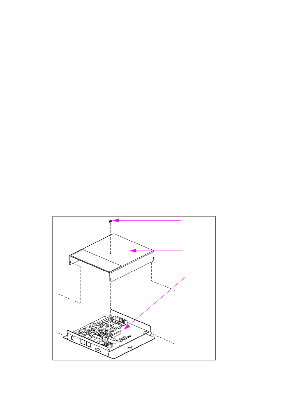
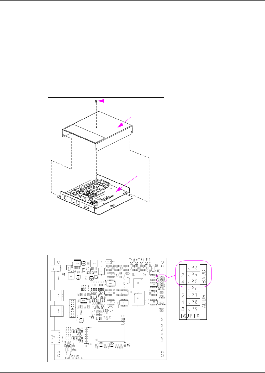
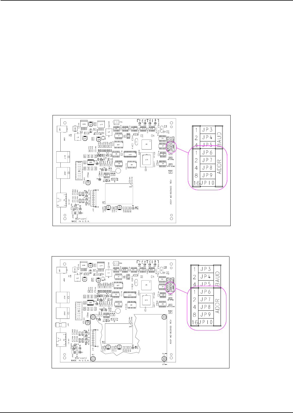
1Remove the Mat Reader Interface Box (M01814A001) cover to access the Logic Board
(M01803A001) as shown in Figure 1.
Figure 1: Mat Reader Interface Box
Cover Screw
Cover
Logic Board
MDE-4017E Mat Reader Assembly Kit C00016-XXX Installation Manual · June 2013 Page 9
Installing Mat Reader Assembly
Preliminary
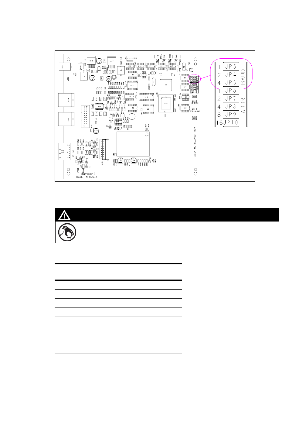
2Locate Jump Jacks on Logic Board for Mat Reader (see Figure 2).
Figure 2: Jump Jacks for Baud Rate Setting on Logic Board
3Set the Jump Jacks as follows (see Figure 2).
A properly grounded ESD wrist strap must be worn while servicing any electronic devices or
components. Failure to use electrostatic precautions may damage electronic components
and void warranty.
CAUTION
Following are the Baud Rate settings:
Mat Reader Baud Rates
Baud Rate (see Note) BAUD 1 BAUD 2 BAUD 4
4800 OUT OUT OUT
2400 IN OUT OUT
1200 OUT IN OUT
300 IN IN OUT
38400 OUT OUT IN
19200 IN OUT IN
9600 OUT IN IN
4800 IN IN IN
Note: 4800 is the default Mat Reader value.
4If you are NOT daisychaining Mat Reader Interface Boxes, reinstall cover removed in step 1
on page 8.
Note: Daisychaining is connecting the output from one interface box to the input of another
and the address of the second Mat Reader must match address on first Mat Reader.
5If you ARE daisychaining Mat Reader Interface Boxes, go to “Addressing Logic Board When
Daisychaining” on page 27 to set addresses on the Logic Board.
Installing Mat Reader Assembly
Page 10 MDE-4017E Mat Reader Assembly Kit C00016-XXX Installation Manual · June 2013
Preliminary
Mounting and Connecting Mat Reader Interface Box
To mount and connect Mat Reader Interface Box, proceed as follows:
1Mount the Mat Reader Interface Box following the procedures in “Mounting Mat Reader
Interface Box” on page 29.
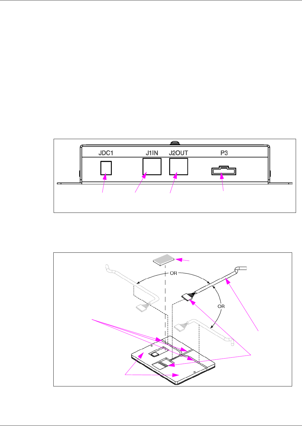
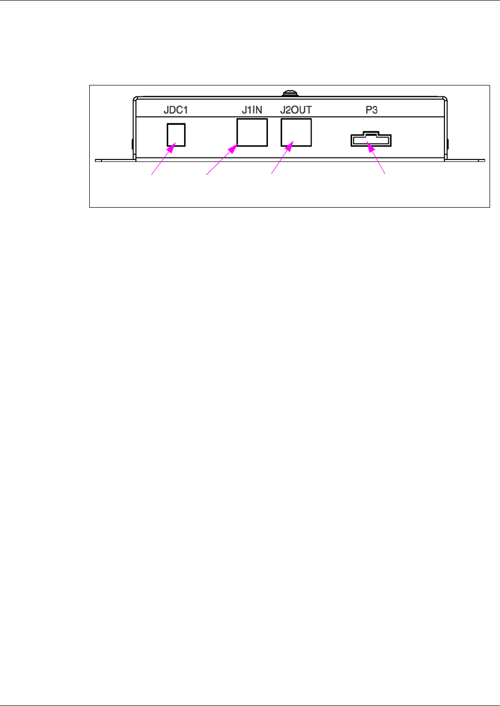
2Run both power and data cables to port end of Mat Reader Interface Box (see Figure 3) as
follows:
a Connect the J3 end of the Ribbon Cable (M01872A001) to the interface P3 Port.
b Connect the P1 end of the CAT-5 Cable to the J1IN Port. The other end will be connected
later.
c If daisychaining interface boxes, connect a CAT-5 Cable from the J2OUT Port on this
interface box to the J1IN Port on the other interface box.
Figure 3: Connecting to Mat Reader Interface Box
Connect Power
Supply here Connect P1
end of CAT-5
cable here
If daisychaining, connect
CAT-5 from J1IN on other
Interface Box here
Connect J3 end of
Mat Reader Drive
Cable here
3Position Mat Reader face down (see Figure 4).
Figure 4: Bottom Side of Mini Mat Reader - Low Frequency
Cable to
Interface Box
Bottom Side of Mini Mat Reader
Three channels
from which to
choose one
(remove neoprene
material from
selected path)
Neoprene Foam Tape
(M024498B001)
Carefully connect
and cover with
Neoprene Foam
Tape
MDE-4017E Mat Reader Assembly Kit C00016-XXX Installation Manual · June 2013 Page 11
Installing Mat Reader Assembly
Preliminary
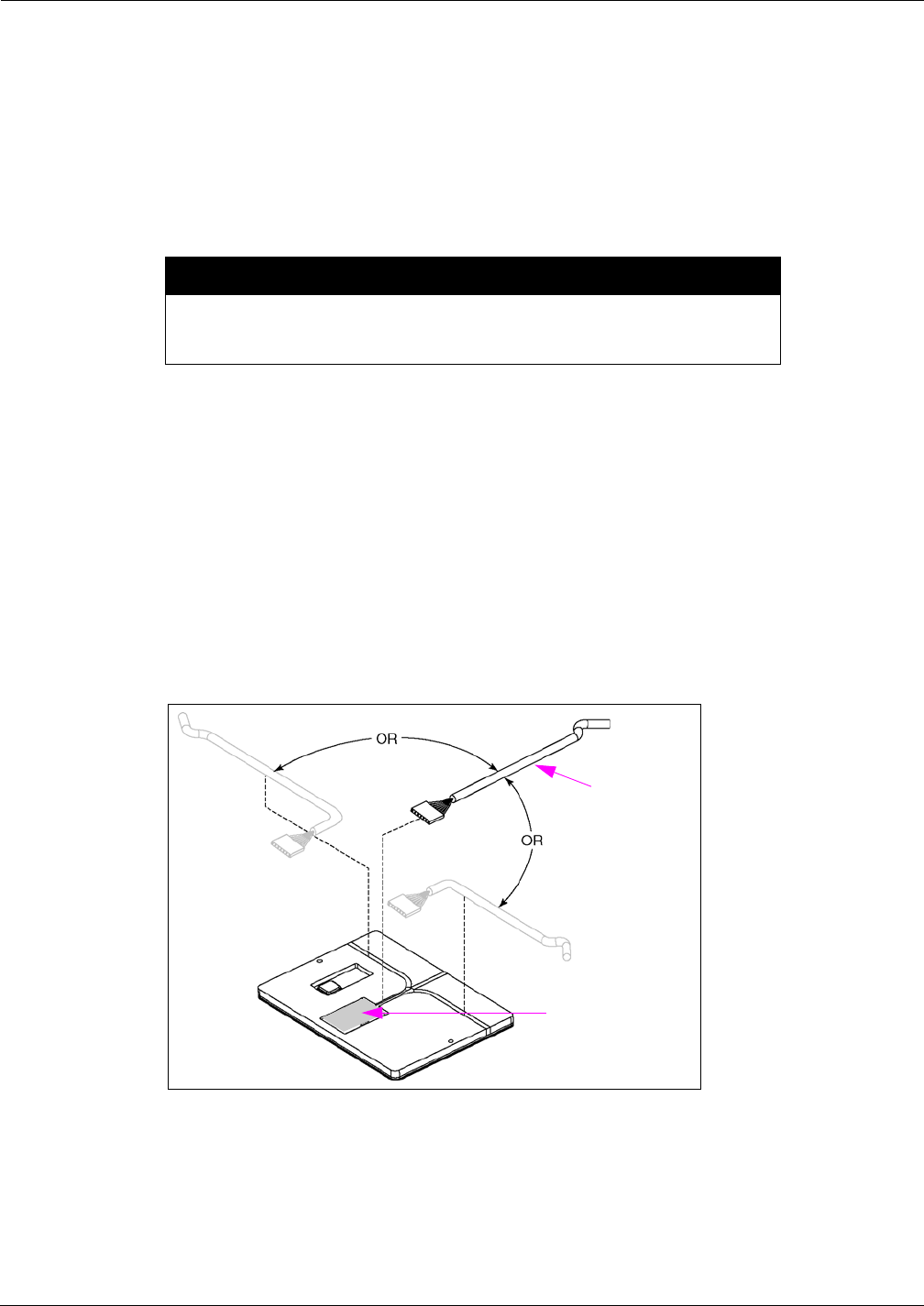
4Select side for Mat Reader Drive Cable (M01872A002) connection based on countertop
configuration requirements.
Note: The Mat Reader is designed to be placed on a countertop beside or adjacent to a cash
register or POS terminal. If properly positioned, the Mat Reader cable will
“disappear” underneath the existing POS equipment. The cable will penetrate the
countertop via the same hole used by the POS power and data cables. Double-sided
tape (not provided) may be used to secure the Mat Reader and/or the cable in position
on the countertop.
Perform the next step by hand. Use of tools (i.e. screwdriver tip or knife blade) will
damage PCB beneath the layer of neoprene, which will render the system
inoperable and void the warranty.
CAUTION
5Using fingers, spread open the precut backing for the cable routing path selected in the
previous step and lift out the neoprene material from that path (see Figure 4 on page 10). Each
cable path has been precut approximately 90 percent through. Lifting out the selected channel
will cause slight tearing of the neoprene material which is to be expected.
6Carefully connect the P1/P2 end of the Mat Reader Drive Cable to the back side of the Mat
Reader, and press the cable into the cable path channel created in step 5 (see Figure 5).
7Peel the backing from the Neoprene Foam Tape (M02498B001) and place over the P1/P2
cable connection (see Figure 5). Ensure to press tape firmly so it contacts the PCB around the
perimeter of the connector.
Figure 5: Connecting to Mini Mat Reader - Low Frequency
P1/P2 Connector
covered by Neoprene
Foam Tape
Cable to
Interface Box
Installing Mat Reader Assembly
Page 12 MDE-4017E Mat Reader Assembly Kit C00016-XXX Installation Manual · June 2013
Preliminary
8Gently turn the Mat Reader to the face-up position (see Figure 6).
Figure 6: MR01003Gxxx Mat Reader - Face Up
9Connect the loose end of the CAT-5 cable to the POS system.
• For a Passport system, the Mat Reader connects to P3 Port on the USB converter using a
Q13180-20B Gender Mender. Refer to MDE-4157 Passport Combined WS Installation
Poster, MDE-4158 Passport Cashier WS Installation Poster, and MDE-4159 Passport
Manager WS Installation Poster.
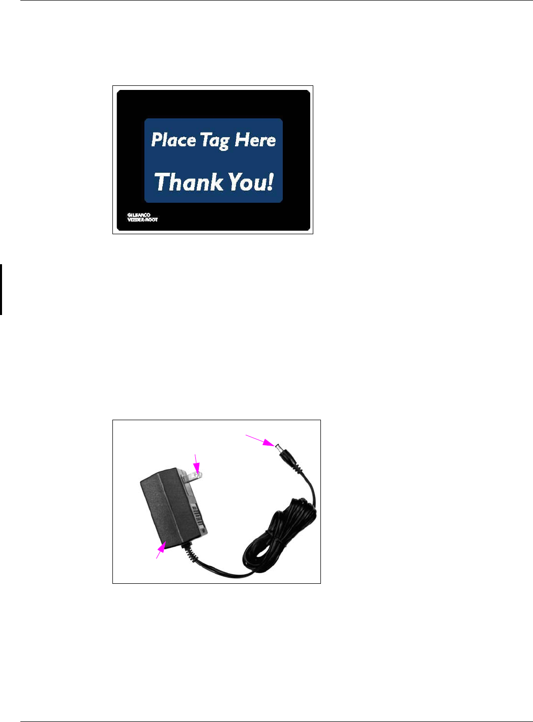
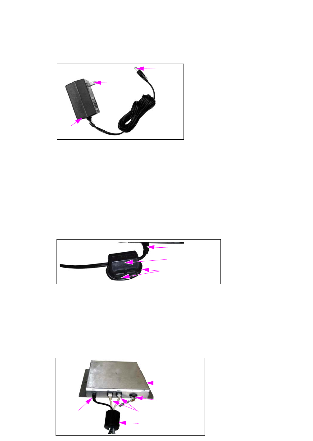
Connecting Wall-mount Power Supply (M01878B001)
To connect the Wall-mount Power Supply provided with kit as shown Figure 7, proceed as
follows:
Figure 7: Wall-mount Power Supply
Wall-mounted
Transformer
Plugs into JDC1 Port
Plugs into AC Power Outlet
1Plug the wall-mounted transformer into the AC power outlet.
Note: This AC power outlet must be on the same circuit as the POS system.
2Connect the plug end of the Power Supply Cable to the JDC1 Port on the Mat Reader Interface
Box (see Figure 3 on page 10).
MDE-4017E Mat Reader Assembly Kit C00016-XXX Installation Manual · June 2013 Page 13
Installing Mat Reader Assembly
Preliminary
3Double loop the JDC1 end of the Power Supply Cable through the Ferrite Bead (Q11433-107)
with the bead in the open position, then snap the bead shut (see Figure 8).
Figure 8: Wall-mount Power Supply Cable with Ferrite
Ferrite (Q11433-107)
Power Supply Cable, Double Looped
Power Supply Cable
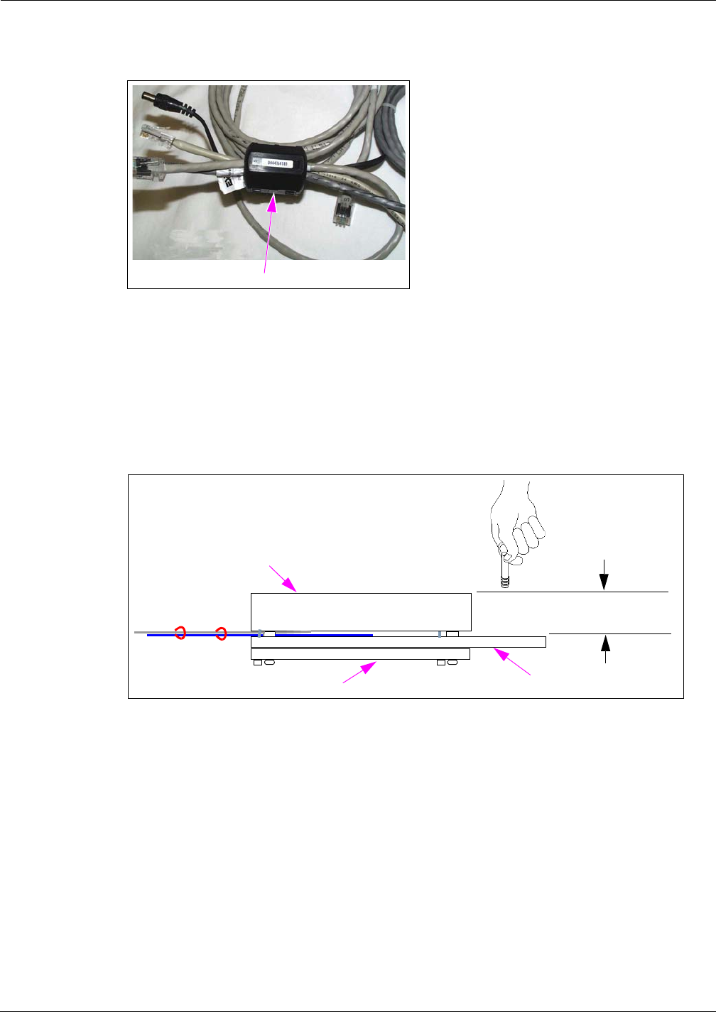
Completing Installation
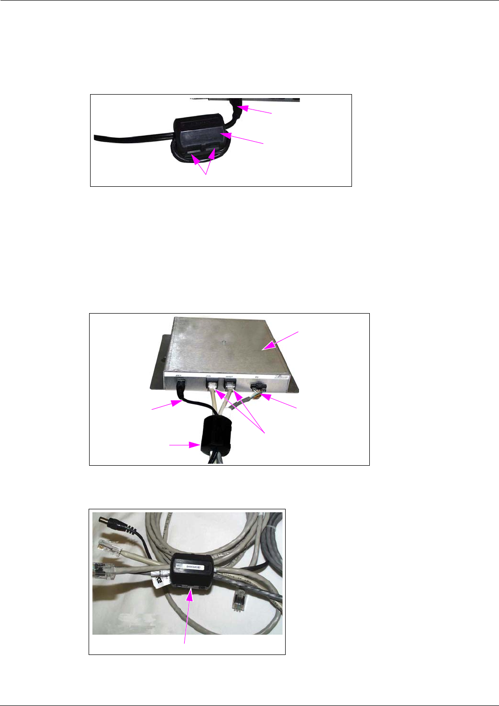
To complete the installation, connect the cables as follows:
1Route all cables near interface box end through Ferrite (Q11433-107) and snap Ferrite closed
(see Figure 9 and Figure 10).
Figure 9: Low Frequency Mini Mat Reader Connections
Power Supply
Cable
CAT-5 Cables
Interface Box to
Mat Reader Cable
Ferrite (Q11433-107)
Interface Box
Figure 10: Ferrite on Interface Cables
Ferrite on Interface Cables
Installing Mat Reader Assembly
Page 14 MDE-4017E Mat Reader Assembly Kit C00016-XXX Installation Manual · June 2013
Preliminary
2Dress all cables and secure with stick on Cable Clamps (Q13459-01).
3Clean up the work area.
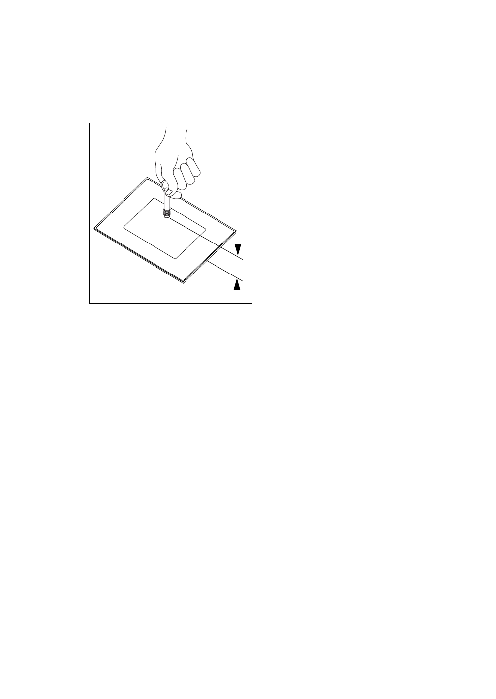
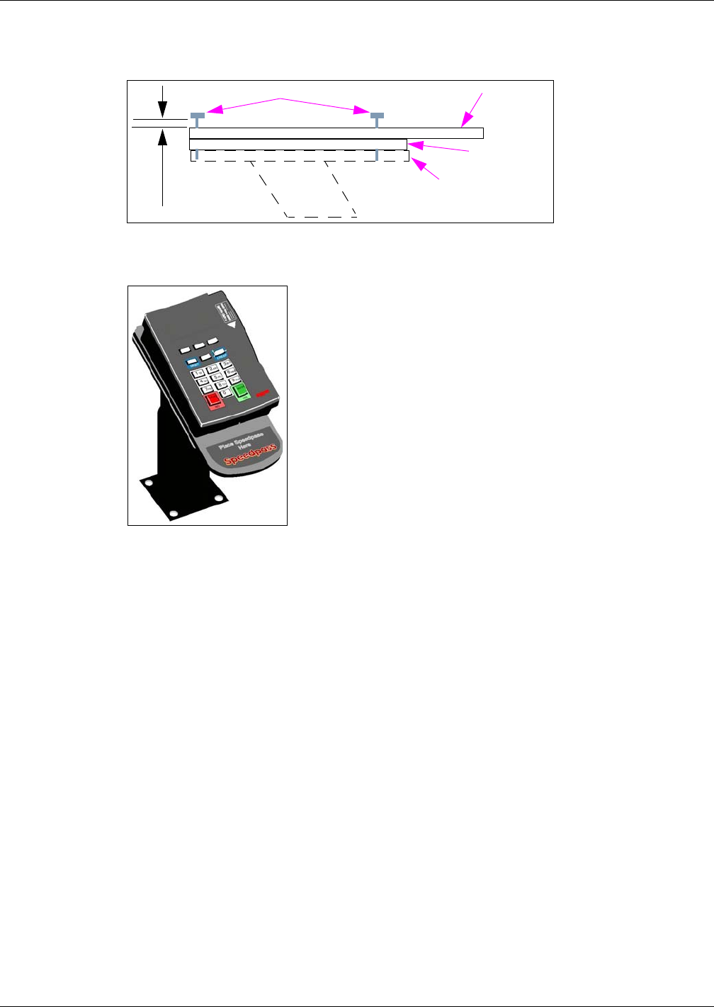
4Ensure the keytag is read by the Mat Reader within the specified range (see Figure 11).
Figure 11: Verifying Low Frequency Mini Mat Reader
2.0 - 4.0” (5 - 10 cm)
10 Go to “Commissioning and Warranty Information” on page 30.
Installing Mat Reader Assembly
MDE-4017E Mat Reader Assembly Kit C00016-XXX Installation Manual · June 2013 Page 15
Preliminary
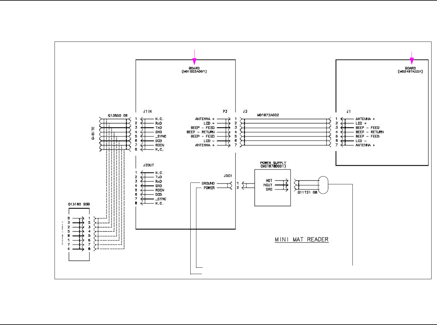
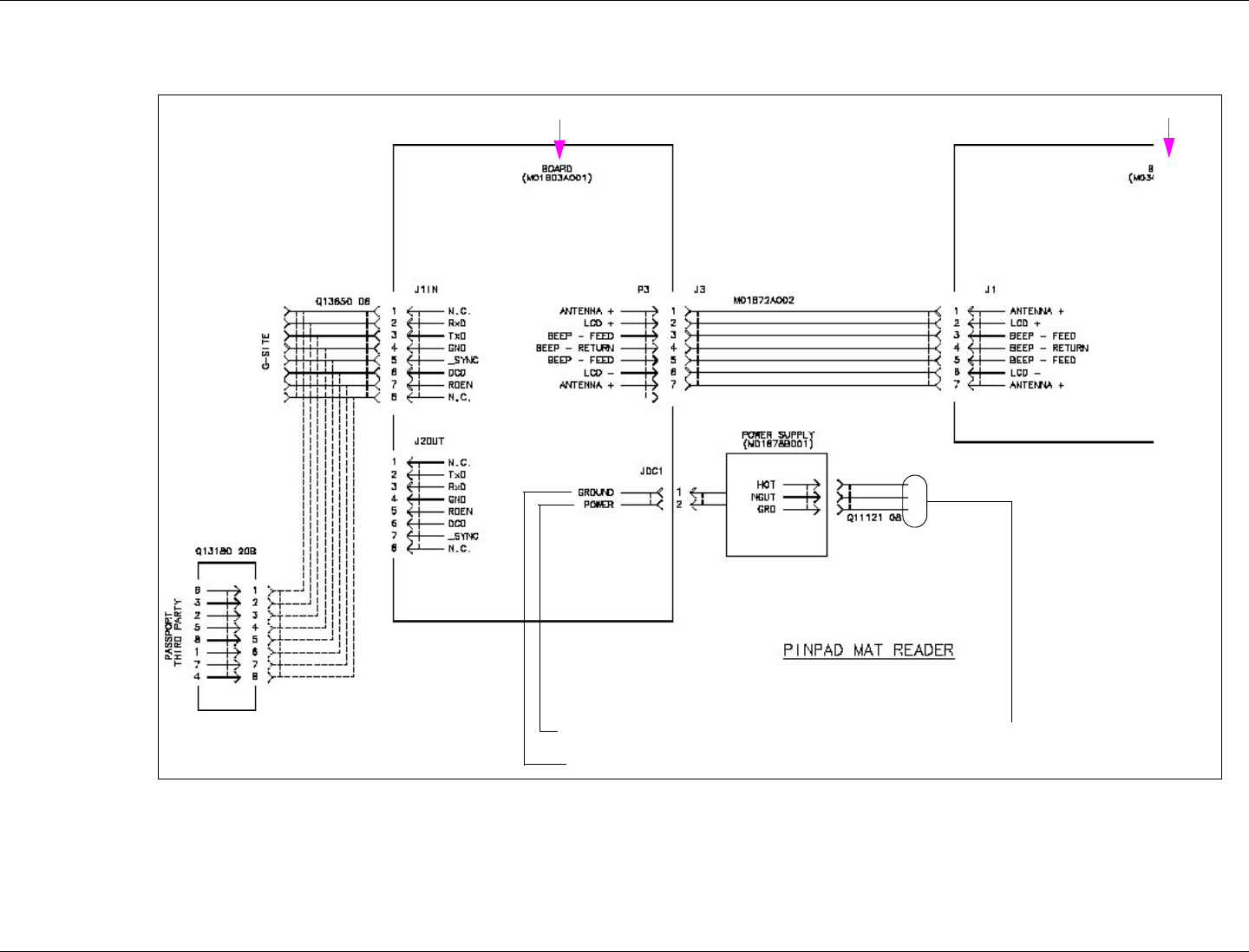
Figure 12: Mat Reader Interconnect/Block Diagram M01873 (Sheet 2 - Mini Mat)
115VAC
DC
+12VDC
In Mat Reader Assembly (MR01003GXXX)
In Interface Box Assembly (M01814A001)
Installing Mat Reader Assembly
Page 16 MDE-4017E Mat Reader Assembly Kit C00016-XXX Installation Manual · June 2013
Preliminary
Installing C00016-011 Kit - Low Frequency (PIN Pad)
To install C00016-011 Kit - Low Frequency (PIN Pad), proceed as follows:
Setting Baud Rate
The set the Baud Rate, proceed as follows:
1Remove the Mat Reader Interface Box cover to access the Logic Board (M01803A001) as
shown in Figure 13.
Figure 13: Mat Reader Interface Box
Cover Screw
Cover
Logic Board
2Locate Jump Jacks on Logic Board for Mat Reader (Figure 14).
Figure 14: Jump Jacks for Baud Rate Setting on Logic Board

MDE-4017E Mat Reader Assembly Kit C00016-XXX Installation Manual · June 2013 Page 17
Installing Mat Reader Assembly
Preliminary
3Set the Jump Jacks as follows (see Figure 14 on page 16).
A properly grounded ESD wrist strap must be worn while servicing any electronic devices or
components. Failure to use electrostatic precautions may damage electronic components
and void warranty.
CAUTION
Following are the Baud Rate settings:
Mat Reader Baud Rates
Baud Rate (see Note) BAUD 1 BAUD 2 BAUD 4
4800 OUT OUT OUT
2400 IN OUT OUT
1200 OUT IN OUT
300 IN IN OUT
38400 OUT OUT IN
19200 IN OUT IN
9600 OUT IN IN
4800 IN IN IN
Note: 4800 is the default Mat Reader Value.
4If you are NOT daisychaining Mat Reader Interface Boxes, reinstall cover removed in step 1
on page 16.
Note: Daisychaining is connecting the output from one Interface Box to the input of another
and the address of the second Mat Reader must match address on first Mat Reader.
5If you ARE daisychaining Mat Reader Interface Boxes, go to “Addressing Logic Board When
Daisychaining” on page 27 to set addresses on the Logic Board.
Mounting and Connecting Mat Reader Interface Box
To mount and connect the Mat Reader Interface Box, proceed as follows:
1Mount the Mat Reader Interface Box following the procedures in “Mounting Mat Reader
Interface Box”on page 29.
2Run both power and data cables to port end of Mat Reader Interface Box (see Figure 15 on
page 18) as follows:
a Connect the J3 end of the Ribbon Cable (M01872A001) to the Interface P3 Port.
b Connect the P1 end of the CAT-5 Cable (Q13850-06) to the J1IN Port. The other end will be
connected later.
Installing Mat Reader Assembly
Page 18 MDE-4017E Mat Reader Assembly Kit C00016-XXX Installation Manual · June 2013
Preliminary
c For daisychaining interface boxes, connect a CAT-5 Cable from the J2OUT Port on this
interface box to the J1IN Port on the other interface box.
Figure 15: Connecting Mat Reader Interface Box
Connect Power
Supply here Connect P1 end of
CAT-5 Cable here
If daisychaining, connect CAT-5
from J1IN on other Interface Box
here
Connect J3 end of Mat
Reader Drive Cable here
PIN Pad Mat Reader - with Pedestal and Hole in Countertop
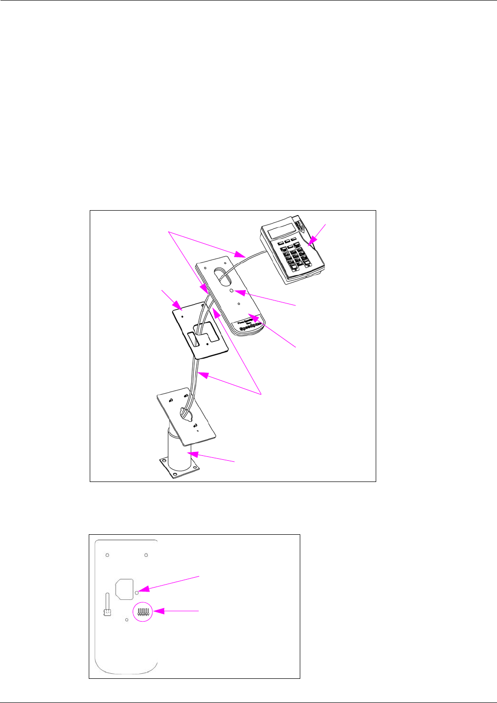
To install the PIN Pad Mat Reader with pedestal and hole in countertop, proceed as follows:
Note: The pedestal will serve as conduit for the PIN Pad Cable (supplied with PIN Pad) and
the Mat Reader Drive Cable (M01872A002).
1If not already installed, use three screws to mount the PIN Pad pedestal over a hole in the
countertop through which the PIN Pad and Mat Reader Drive Cables will be routed.
2Route the Mat Reader Drive Cable from the Interface Box through the pedestal and through
the L-shaped hole in the PIN Pad Adapter Plate (M03182B001) as shown in Figure 16 on
page 19.
3Carefully connect the P1/P2 Connector of the Mat Reader Drive Cable to the connector on the
back of the PIN Pad Mat Reader (see Figure 17 on page 19).
4Route cable-tie through designated hole in PIN Pad Mat Reader (see Figure 16 on page 19 and
Figure 17 on page 19) and around Mat Reader Drive Cable, and pull cable-tie end through its
locking slot. This provides strain relief for the cable.
5Route the PIN Pad Cable from the Passport System through the pedestal, L-shaped hole in the
PIN Pad Adapter Plate, and PIN Pad Mat Reader (see Figure 16 on page 19).
6Carefully connect the connector on the PIN Pad Cable to the connector on the back of the PIN
Pad.
7Place the three Q11270-38 Screws through the corresponding holes in the PIN Pad Mat Reader
and the adapter plate, and screw into the corresponding holes in the pedestal leaving the screw
heads 0.160 inches (4 mm) above the top of the PIN Pad Mat Reader (see Figure 19 on
page 20).
8Align the three mounting holes on the bottom of the PIN Pad over the three screws on the
pedestal/PIN Pad Adapter Plate/PIN Pad Mat Reader combination.
9Place the PIN Pad on the Pedestal/PIN Pad Adapter Plate/PIN Pad Mat Reader combination so
that the screws go into the PIN Pad’s mounting holes.
MDE-4017E Mat Reader Assembly Kit C00016-XXX Installation Manual · June 2013 Page 19
Installing Mat Reader Assembly
Preliminary
10 Gently slide the PIN Pad down the Pedestal/PIN Pad Adapter Plate/pin Pad Mat Reader
combination so that the screws fit firmly into the slot holes.
11 Tighten the screw on the bottom of the angled plate on the pedestal to lock the Pedestal/PIN
Pad Adapter Plate/PIN Pad Mat Reader combination in place. For PIN Pad and Mat Reader
Assembly, see Figure 19 on page 20.
12 Connect the loose end of the CAT-5 Cable from the interface box to P3 Port on the USB
converter. Refer to MDE-4157 Passport Combined WS Installation Poster, MDE-4158
Passport Cashier WS Installation Poster, and MDE-4159 Passport Manager WS Installation
Poster.
Figure 16: Routing PIN Pad Mat Reader Cable Through Pedestal
PIN Pad
Pedestal
PIN Pad Adapter
Plate
PIN Pad Mat Reader
Mat Reader Drive Cable
PIN Pad Cable from
Passport System
Hole for cable-tie to
secure Mat Reader
Drive Cable
Figure 17: Back Side of PIN Pad Mat Reader
Connect P1/P2 end of Mat
Reader Drive Cable here
Hole for cable-tie to secure
Mat Reader Drive Cable
Installing Mat Reader Assembly
Page 20 MDE-4017E Mat Reader Assembly Kit C00016-XXX Installation Manual · June 2013
Preliminary
Figure 18: Screw Head Height Above PIN Pad Mat Reader
PIN Pad Mat
Reader
PIN Pad
Adapter Plate
Screw
0.160”
(4 mm)
Pedestal Top
Figure 19: PIN Pad Mat Reader Assembly on Pedestal
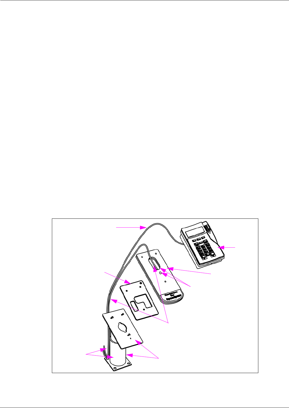
PIN Pad Mat Reader - With Pedestal and Without Hole in Countertop
Note: The pedestal will serve as support for the PIN Pad and Mat Reader. The PIN Pad Cable
(supplied with PIN Pad) and Mat Reader Drive Cable (M01872A002) will be routed
between the Mat Reader and PIN Pad, and secured to the outside of the pedestal.
1If not already installed, use three screws to mount the PIN Pad pedestal to the countertop.
2Route the Mat Reader Drive Cable from the interface box beside the pedestal and through the
hole in the top of the PIN Pad Adapter Plate [M03182B001 (see Figure 20 on page 21)].
3Carefully connect the P1/P2 Connector of the Mat Reader Drive Cable to the connector on the
back of the PIN Pad Mat Reader (see Figure 17 on page 19).
4Route Cable-tie (Q10178-01) through designated hole in PIN Pad Mat Reader (see Figure 20
on page 19) and around Mat Reader Drive Cable and pull cable-tie end through its locking
slot. This provides strain relief for the cable.
5Route the PIN Pad Cable from the Passport System beside the pedestal across the top of the
PIN Pad Mat Reader (see Figure 20 on page 21).
6Carefully connect the connector on the PIN Pad Cable to the connector on the back of the PIN
Pad.
MDE-4017E Mat Reader Assembly Kit C00016-XXX Installation Manual · June 2013 Page 21
Installing Mat Reader Assembly
Preliminary
7Place the three Q11270-38 Screws through the corresponding holes in the PIN Pad Mat Reader
and the adapter plate, and screw into the corresponding holes in the pedestal leaving the screw
heads 0.160 inches (4 mm) above the top of the PIN Pad Mat Reader.
8Align the three mounting holes on the bottom of the PIN Pad over the three screws on the
pedestal/PIN Pad Adapter Plate/PIN Pad Mat Reader combination.
9Place the PIN Pad on the pedestal/PIN Pad Adapter Plate/PIN Pad Mat Reader combination so
that the screws go into the PIN Pad’s mounting holes.
10 Gently slide the PIN Pad down the pedestal/PIN Pad Adapter Plate/PIN Pad Mat Reader
combination so that the screws fit firmly into the slot holes.
11 Tighten the screw on the bottom of the angled plate on the pedestal to lock the pedestal/PIN
Pad Adapter Plate/PIN Pad Mat Reader combination in place (for PIN Pad and Mat Reader
Assembly, see Figure 22 on page 23.).
12 Secure the PIN Pad Cable from the Passport System and the Mat Reader Drive Cable to the
pedestal with cable-ties (see Figure 19 on page 20).
13 Connect the loose end of the CAT-5 Cable from the interface box to P3 Port on the USB
converter. Refer to MDE-4157 Passport Combined WS Installation Poster, MDE-4158
Passport Cashier WS Installation Poster, and MDE-4159 Passport Manager WS Installation
Poster.
Figure 20: Routing PIN Pad Mat Reader Cable - Outside Pedestal
PIN Pad
Pedestal
PIN Pad Adapter
Plate PIN Pad Mat Reader
Mat Reader Drive Cable
PIN Pad Cable
from Passport
System
Cable-tie to secure Mat Reader
Drive Cable goes here
Cable-ties (not
provided in kit)
goes here

Installing Mat Reader Assembly
Page 22 MDE-4017E Mat Reader Assembly Kit C00016-XXX Installation Manual · June 2013
Preliminary
PIN Pad Mat Reader - Without Pedestal and Hole in Countertop
To install the PIN Pad Mat Reader without pedestal and hole in countertop, proceed as
follows:
Note: The PIN Pad Cable (supplied with PIN Pad) and Mat Reader Drive Cable
((M01872A002) are routed between the Mat Reader and PIN Pad. The four Rubber
Bumpers (Q12226-01) are attached to the back of the PIN Pad Adapter Plate
(M03182B001) to keep it off the countertop.
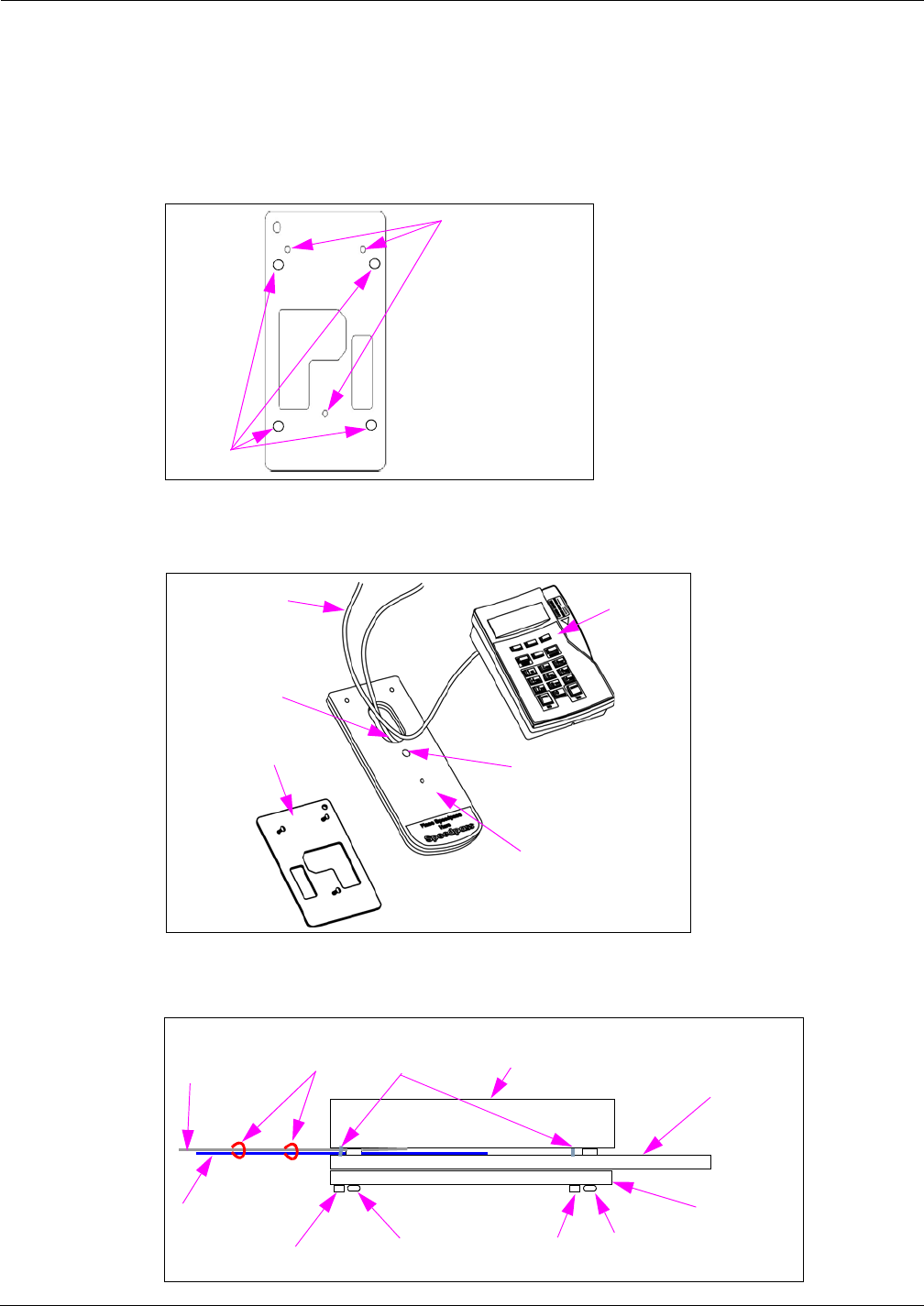
1Place the PIN Pad Adapter Plate face down on a clean, shock absorbing material (such as
corrugated cardboard or thick shop rag); then firmly hammer the three Q10227-06 Clinch Nuts
into the three holes in the back side of the PIN Pad Adapter Plate (see Figure 21 on page 23).
2Attach the four adhesive-backed Rubber Bumpers to the back side of the PIN Pad Adapter
Plate in the four corners (see Figure 28 on page 25).
3Route the Mat Reader Drive Cable from the interface box down through the D-shaped hole in
the PIN Pad Mat Reader [M02001GXXX (see Figure 22 on page 23)].
4Carefully connect the P1/P2 connector of the Mat Reader Drive Cable to the connector on the
back of the PIN Pad Mat Reader (see Figure 17 on page 19).
5Route Cable-tie (Q10178-01) through designated hole in PIN Pad Mat Reader (see Figure 22
on page 23 and Figure 17 on page 19) and around Mat Reader Drive Cable and pull cable-tie
end through its locking slot. The cable-tie provides strain relief for the cable.
6Route the PIN Pad Cable from the Passport System directly out of the back of the PIN Pad
(see Figure 22 on page 23).
7Carefully connect the connector on the PIN Pad Cable to the connector on the back of the PIN
Pad.
8Place the three Q11270-21 Screws through the screw holes in the PIN Pad Mat Reader into the
front of the PIN Pad Adapter Plate; and screw into the clinch nuts in the PIN Pad Adapter Plate
leaving the screw heads 0.160 inches (4 mm) above the top of the PIN Pad Mat Reader.
9Align the three mounting holes on the bottom of the PIN Pad over the three screws on the PIN
Pad Adapter Plate/PIN Pad Mat Reader combination.
10 Place the PIN Pad on the PIN Pad Adapter Plate/PIN Pad Mat Reader combination so that the
screws go into the PIN Pad’s mounting holes.
11 Gently slide the PIN Pad down the PIN Pad Adapter Plate/PIN Pad Mat Reader combination
so that the screws fit firmly into the slot holes to form the PIN Pad Adapter Plate/PIN Pad Mat
Reader/PIN Pad unit (see Figure 23 on page 23).
12 Use remaining cable-ties to secure Mat Reader and PIN Pad Cables together for neat
appearance on countertop (see Figure 23 on page 23).
MDE-4017E Mat Reader Assembly Kit C00016-XXX Installation Manual · June 2013 Page 23
Installing Mat Reader Assembly
Preliminary
13 Connect the loose end of the CAT-5 Cable from the interface box to P3 Port on the USB
converter. Refer to MDE-4157 Passport Combined WS Installation Poster, MDE-4158
Passport Cashier WS Installation Poster, and MDE-4159 Passport Manager WS Installation
Poster.
Figure 21: M01382 Adapter Plate - Back Side with Bumpers and Nut Locations
Gently hammer
Q10227-06 Clinch
Nuts into these holes
Rubber
Bumper
Figure 22: Routing PIN Pad Mat Reader Cable Without Pedestal
PIN Pad
PIN Pad Adapter
Plate
PIN Pad Mat Reader
Mat Reader
Drive Cable
PIN Pad Cable
from Passport
System
Attach cable-tie here to
secure Mat Reader Drive
Cable
Figure 23: PIN Pad Adapter Plate/PIN Pad Mat Reader Combination/PIN Pad Unit
Rubber
Bumper
Everest PIN Pad
PIN Pad Mat
Reader
PIN Pad
Adapter Plate
Mat Reader
Drive Cable
PIN Pad Cable
from Passport
System Screw
Clinch Nut
Clinch Nut Rubber
Bumper
Cable-ties
Installing Mat Reader Assembly
Page 24 MDE-4017E Mat Reader Assembly Kit C00016-XXX Installation Manual · June 2013
Preliminary
Connecting Wall-mount Power Supply (M01878B001)
To connect the Wall-mount Power Supply provided with kit as shown in Figure 24, proceed as
follows:
Figure 24: Wall-mount Power Supply
Wall-mounted
Transformer
Plugs into
JDC1 Port
Plugs into AC
Power Outlet
1Plug the wall-mounted transformer into the AC power outlet.
Note: This AC power outlet must be on the same circuit as the POS system.
2Connect the plug end of the Power Supply Cable to the JDC1 Port on the Mat Reader Interface
Box (see Figure 15 on page 18).
Double loop the JDC1 end of the Power Supply Cable through the Ferrite Bead (Q11433-107)
with the bead in the open position, then snap the bead shut (see Figure 25).
Figure 25: Wall-mount Power Supply Cable with Ferrite
Ferrite (Q11433-107)
Power Supply Cable,
Double Looped
Power Supply Cable
Completing Installation
To complete the installation, connect the cables as follows:
1Route all cables near interface box end through Ferrite (Q11433-107) and snap Ferrite closed
(see Figure 26 and Figure 27 on page 25).
Figure 26: Low Frequency Mini Mat Reader Connections
Power Supply
Cable CAT-5 Cables
Interface Box-to-Mat
Reader Cable
Ferrite(Q11433-107)
Interface Box
MDE-4017E Mat Reader Assembly Kit C00016-XXX Installation Manual · June 2013 Page 25
Installing Mat Reader Assembly
Preliminary
Figure 27: Ferrite on Interface Cables
Ferrite on Interface Cables
2Dress all cables and secure with stick on Cable Clamps (Q13459-01).
3Clean up the work area.
4Verify the keytag can be read by the Mat Reader within the specified range (see Figure 28).
Figure 28: PIN Pad Mat Reader Read Verification
PIN Pad Mat Reader (MR02001GXXX)
PIN Pad Adapter Plate (M03182B001)
PIN Pad
2.0 - 4.0 Inches
(5 - 10 cm)
5Go to “Commissioning and Warranty Information” on page page 30.
Installing Mat Reader Assembly
Page 26 MDE-4017E Mat Reader Assembly Kit C00016-XXX Installation Manual · June 2013
Preliminary
Figure 29: Mat Reader Interconnect/Block Diagram M01873 (Sheet 3 - PIN Pad)
115VAC
In Mat Reader AssemblyIn Interface Box Assembly
DC
+12VDC
MDE-4017E Mat Reader Assembly Kit C00016-XXX Installation Manual · June 2013 Page 27
Installing Mat Reader Assembly
Preliminary
Addressing Logic Board When Daisychaining
Address for Mat Reader must match address on previously installed Mat Reader.
To set the address on Logic Board when daisychaining, proceed as follows:
1Access Logic Board for Mat Reader being installed.
2Locate Jump Jacks on previously installed Mat Reader Logic Board M01803A001 or
M01803A002 as appropriate (see Figure 30 or Figure 31).
Figure 30: Jump Jacks for Address Setting on M01803A001 Logic Board
Figure 31: Jump Jacks for Address Setting on M01803A002 Logic Board
3Note position of jump jacks on previously installed Mat Reader Logic Board, and set Jump
Jacks on board for Mat Reader being installed to match address on Logic Board (see Caution
on page 28).

A properly grounded ESD wrist strap must be worn while servicing any electronic devices or
components. Failure to use electrostatic precautions may damage electronic components
and void warranty.
CAUTION
Mat Reader Addresses
Address on Logic Board
M01803A001/M01803A002 ADDR 1 ADDR 2 ADDR 4 ADDR 8 ADDR 16
0OUT OUT OUT OUT OUT
1IN OUT OUT OUT OUT
2OUT IN OUT OUT OUT
3IN IN OUT OUT OUT
4OUT OUT IN OUT OUT
5IN OUT IN OUT OUT
6OUT IN IN OUT OUT
7IN IN IN OUT OUT
8OUT OUT OUT IN OUT
9IN OUT OUT IN OUT
10 OUT IN OUT IN OUT
11 IN IN OUT IN OUT
12 OUT OUT IN IN OUT
13 IN OUT IN IN OUT
14 OUT IN IN IN OUT
15 IN IN IN IN OUT
16 OUT OUT OUT OUT IN
17 IN OUT OUT OUT IN
18 OUT IN OUT OUT IN
19 IN IN OUT OUT IN
20 OUT OUT IN OUT IN
21 IN OUT IN OUT IN
22 OUT IN IN OUT IN
23 IN IN IN OUT IN
24 OUT OUT OUT IN IN
25 IN OUT OUT IN IN
26 OUT IN OUT IN IN
27 IN IN OUT IN IN
28 OUT OUT IN IN IN
29 IN OUT IN IN IN
30 OUT IN IN IN IN
31 IN IN IN IN IN
Installing Mat Reader Assembly
Page 28 MDE-4017E Mat Reader Assembly Kit C00016-XXX Installation Manual · June 2013
Preliminary
4Reinstall the cover.
MDE-4017E Mat Reader Assembly Kit C00016-XXX Installation Manual · June 2013 Page 29
Installing Mat Reader Assembly
Preliminary
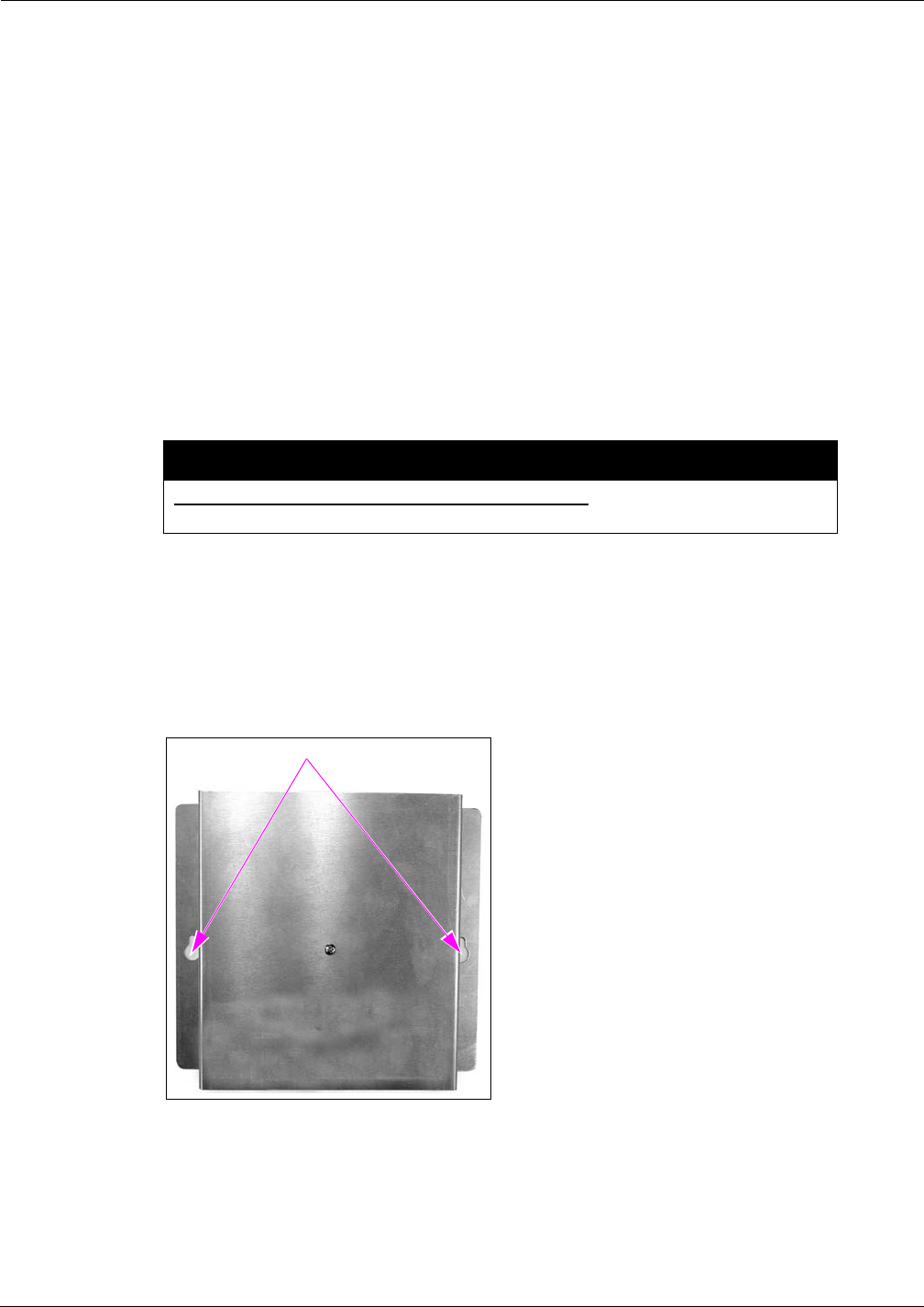
Mounting Mat Reader Interface Box
To mount the Mat Reader Interface box, proceed as follows:
1Determine the location for the installation of indoor equipment. The interface box may be
mounted under the countertop (upside down) or vertically on one of the supporting walls of
the countertop.
Note: For connecting Mat Reader Interface Box to Mat Reader, refer to MDE-3620 Gilbarco
POS Console Site Preparation Manual. Also refer to “Interface Box”on page 8.
2Use a Zircon stud/bracket finder to ensure no electrical conduits or pipes are located inside the
wall where the Mat Reader Interface Box is to be mounted. Also, ensure the Mat Reader
Interface Box is to be located where studs or wall (concrete/brick/drywall) mollys can be used
for mounting.
3
Do not use the Mat Reader Interface Box as a drill guide. It may be used as a template to
mark the holes to be drilled.
CAUTION
Mark and drill holes. Insert wall mollys if required.
4Use 8-32-inch Thread-forming Screws provided or other appropriate contractor-supplied
mounting hardware to secure the Mat Reader Interface Box to the wall or under countertop.
Note: 3/8 inches deep pilot holes (approximately 1/8 inches diameter) are required if the
screws provided are used.
Figure 32: Mat Reader Interface Box Mounting Holes
Mounting Holes

© 2013 Gilbarco Inc.
7300 West Friendly Avenue · Post Office Box 22087
Greensboro, North Carolina 27420
Phone (336) 547-5000 · http://www.gilbarco.com · Printed in the U.S.A.
MDE-4017E Mat Reader Assembly Kit C00016-XXX Installation Manual · June 2013
G-SITE®, Gilbarco®, and Passport® are registered trademarks of Gilbarco Inc. Corian® is a registered trademark of E.I. Du Pont De
Nemours and Company. Everest® is a registered trademark of VeriFone Inc. Formica® is a registered trademark of Formica Corporation.
IC® is a registered trademark of Industry Canada. Phillips® is a registered trademark of Phillips Screw Company. UL® is a registered
trademark of Underwriters’ Laboratories, Inc. Zircon® is a registered trademark of Zircon International Inc.
Preliminary
Commissioning and Warranty Information
Commissioning and Warranty Information
Upon completion and testing the Mat Reader system, call the Gilbarco Call Center at
1-888-800-7498 to register the installation and activate the warranty.
Note: The installed unit’s full model (C00016-XXX) and serial number are required to register
the installation and activate the warranty.
• All Mat Readers have one-year parts warranty.
Note: Parts are to be returned through and obtained from the local Gilbarco distributor.
• Labor warranty, if any, is unit and customer specific.
Gilbarco strongly recommends using only Gilbarco trained ASCs to perform service on the
units. Use of non-authorized service personnel to repair or service these units may void
warranty. Call your local distributor for service.