Gilbarco LFSQR TRIND M01560 Module User Manual 13 0072 Exhibit Cover
Gilbarco Inc. TRIND M01560 Module 13 0072 Exhibit Cover
Gilbarco >
Manual

5015 B.U. Bowman Drive Buford, GA 30518 USA Voice: 770-831-8048 Fax: 770-831-8598
Certification Exhibit
FCC ID: N6SLFSQR
IC: 827B-LFSQR
FCC Rule Part: 15.209
IC Radio Standards Specification: RSS-210
ACS Project Number: 13-0072
Manufacturer: Gilbarco, Inc.
Model: LFSQR

The Advantage® Series, MPD® -3, Encore®, and
Eclipse® Units
TRIND® Start-up, Service, and
Parts Manual
MDE-3664B
Computer Programs and Documentation
All Gilbarco Inc. and/or Veeder Root Company computer programs (including software on diskettes and within memory chips) and documentation are copyrighted by, and shall
remain the property of, Gilbarco Inc. and/or Veeder Root Company. Such computer programs and documents may also contain trade secret information. The duplication, disclosure,
modification, or unauthorized use of computer programs or documentation is strictly prohibited, unless otherwise licensed by Gilbarco Inc. and/or Veeder Root Company.
Federal Communications Commission (FCC) Warning
This equipment has been tested and found to comply with the limits for a Class A digital device pursuant to Part 15 of the FCC Rules. These limits are designed to provide
reasonable protection against harmful interference when the equipment is operated in a commercial environment. This equipment generates, uses, and can radiate radio frequency
energy, and if not installed and used in accordance with the instruction manual, may cause harmful interference to radio communications. Operation of this equipment in a residential
area is likely to cause harmful interference in which case the user will be required to correct the interference at his own expense. Changes or modifications not expressly approved by
the manufacturer could void the user’s authority to operate this equipment.
Industry Canada Warning
This device complies with Industry Canada licence-exempt RSS standard(s). Operation is subject to the following two conditions:
• this device may not cause interference, and
• this device must accept any interference, including interference that may cause undesired operation of the device.
Le présent appareil est conforme aux CNR d’Industrie Canada applicables aux appareils radio exempts de licence. L’exploitation est autorisée aux deux conditions suivantes :
• l’appareil ne doit pas produire de brouillage, et
• l’utilisateur de l’appareil doit accepter tout brouillage radioélectrique subi, même si le brouillage est susceptible d’en compromettre le fonctionnement.
Under Industry Canada regulations, this radio transmitter may only operate using an antenna of a type and maximum (or lesser) gain approved for the transmitter by Industry
Canada. To reduce potential radio interference to other users, the antenna type and its gain should be so chosen that the equivalent isotropically radiated power (e.i.r.p.) is not more
than that necessary for successful communication.
Conformément à la réglementation d’Industrie Canada, le présent émetteur radio peut fonctionner avec une antenne d’un type et d’un gain maximal (ou inférieur) approuvé pour
l’émetteur par Industrie Canada. Dans le but de réduire les risques de brouillage radioélectrique à l’intention des autres utilisateurs, il faut choisir le type d’antenne et son gain de
sorte que la puissance isotrope rayonnée équivalente (p.i.r.e.) ne dépasse pas l’intensité nécessaire à l’établissement d'une communication satisfaisante.
Approvals
Trademarks
Gilbarco is an ISO 9001:2008 registered company.
Underwriters Laboratories (UL):
U L File# Products listed with U L
MH1941 All Gilbarco pumps and dispensers that bear
the UL listing mark.
MH8467 Transac System 1000 and PAM 1000
E105106 Dell DHM Minitower
E165027 G-SITE and Passport Systems
National Conference of Weights and Measures (NCWM) - Certificate of Conformance (CoC):
Gilbarco pumps and dispensers are evaluated by NCWM under the National Type Evaluation Program (NTEP). NCWM has issued the following CoC:
CoC# Product Model # CoC# Product Model #
02-019 Encore Nxx 02-036 Legacy Jxxx
02-020 Eclipse Exx
02-037
G-SITE Printer (Epson) PA0307
02-025 Meter - C Series PA024NC10 G-SITE Distribution Box PA0306
Meter - C Series PA024TC10 G-SITE Keyboard PA0304
02-029 CRIND — G-SITE Mini Tower PA0301
02-030
TS-1000 Console — G-SITE Monitor PA0303
TS-1000 Controller PA0241 G-SITE Printer (Citizen) PA0308
Distribution Box PA0242 02-038 C+ Meter T19976
Meter - EC Series PA024EC10 02-039 Passport PA0324
VaporVac Kits CV 02-040 Ecometer T20453
05-001 Titan KXXY Series
California Air Resources Board (CARB):
Executive Order # Product
G-70-52-AM Balance Vapor Recovery
G-70-150-AE VaporVac
Registered trademarks
CRIND®InfoScreen®Transac®
Dimension® Series Legacy®Transac® System 1000
e-CRIND®Making Things Better®Trimline®
Eclipse®MPD®TRIND®
Encore®Passport®VaporVac®
G-SITE®Performer®
Gilbarco®The Advantage® Series
Additional US and foreign trademarks pending.
Other brand or product names shown may be
trademarks or registered trademarks of their
respective holders.
Non-registered trademarks
Applause™ Media System G-SITE® Lite™SMART Meter™
CIM™Highline™SmartPad™
C-PAM™Horizon™Surge Management System™
ECR™MultiLine™Tank Monitor™
EMC™Optimum™ Series TCR™
FlexPay™PAM™ 1000 Titan™
G-CAT™PAM™Ultra-Hi™
Gilbert™SMART Connect™ValueLine™
G-SITE® Link™SMART CRIND™
This document is subject to change without notice.
E-mail: literature@gilbarco.com · Internet: http://www.gilbarco.com
2013 Gilbarco Inc. All Rights Reserved

MDE-3664B TRIND® Start-up, Service, and Parts Manual · June 2013 Page i
Table of Contents
Table of Contents
1 – Introduction 1-1
TRIND® Overview. . . . . . . . . . . . . . . . . . . . . . . . . . . . . . . . . . . . . . . . . . . . . . . . . . . . . . . . . . . . . . . . 1-1
About TRIND . . . . . . . . . . . . . . . . . . . . . . . . . . . . . . . . . . . . . . . . . . . . . 1-1
How TRIND Works . . . . . . . . . . . . . . . . . . . . . . . . . . . . . . . . . . . . . . . . . . . . . . . . . . . . . . . . . . . . . . . 1-2
Related Documents. . . . . . . . . . . . . . . . . . . . . . . . . . . . . . . . . . . . . . . . . . . . . . . . . . . . . . . . . . . . . . . 1-3
Abbreviations and Acronyms. . . . . . . . . . . . . . . . . . . . . . . . . . . . . . . . . . . . . . . . . . . . . . . . . . . . . . . . 1-3
TRIND Kit Coverage . . . . . . . . . . . . . . . . . . . . . . . . . . . . . . . . . . . . . . . . . . . . . . . . . . . . . . . . . . . . . . 1-5
2 – Important Safety Information 2-1
3 – Systems Overview 3-1
Full Systems . . . . . . . . . . . . . . . . . . . . . . . . . . . . . . . . . . . . . . . . . . . . . . . . . . . . . . . . . . . . . . . . . . . . 3-1
Hand-held Only Tag System Overview . . . . . . . . . . . . . . . . . . . . . . . . . . . . . . . . . . . . . . . . . . . . . . . . 3-4
4 – Major Hardware Components 4-1
Card Cage Assemblies . . . . . . . . . . . . . . . . . . . . . . . . . . . . . . . . . . . . . . . . . . . . . . . . . . . . . . . . . . . . 4-1
T20229-G1 Card Cage Assembly . . . . . . . . . . . . . . . . . . . . . . . . . . . . . 4-1
T20606-G2 Card Cage Assembly . . . . . . . . . . . . . . . . . . . . . . . . . . . . . 4-2
T20606-G3 Card Cage Assembly . . . . . . . . . . . . . . . . . . . . . . . . . . . . . 4-3
T20606-G5 Card Cage Assembly . . . . . . . . . . . . . . . . . . . . . . . . . . . . . 4-4
Disassembly and Installation for MPD-3 Units with SID Displays . . . . . 4-5
Disassembly and Installation for All MPD-3 Units . . . . . . . . . . . . . . . . . 4-5
AC EMI Line Filter (Q10895) . . . . . . . . . . . . . . . . . . . . . . . . . . . . . . . . . 4-6
R20600 and R20719 Transformers . . . . . . . . . . . . . . . . . . . . . . . . . . . . 4-6
T20138 and T20314 Power Supply Boards . . . . . . . . . . . . . . . . . . . . . . 4-6
Q13563 Data Control Boards. . . . . . . . . . . . . . . . . . . . . . . . . . . . . . . . . 4-7
UHF Receiver Board (Q13564) . . . . . . . . . . . . . . . . . . . . . . . . . . . . . . . 4-8
Q13579 Transmitter Board. . . . . . . . . . . . . . . . . . . . . . . . . . . . . . . . . . . 4-9
T20128 and T20678 Gateway Boards . . . . . . . . . . . . . . . . . . . . . . . . . 4-10
Card Cage Cable Harness (T20662-G2) . . . . . . . . . . . . . . . . . . . . . . . 4-11
Full System TRIND Transmitter Cable (R20520-G1). . . . . . . . . . . . . . 4-11
Full System TRIND RS-485 Communication Cable (R20525-G1). . . . 4-12
Full System TRIND Power Supply Cables (R20763-GX). . . . . . . . . . . 4-12
Hand-held TRIND System Ribbon Cable (M00507) . . . . . . . . . . . . . . 4-13
Hand-held TRIND System Power Cable (M01366) . . . . . . . . . . . . . . . 4-13
TRIND Overhead Antennas. . . . . . . . . . . . . . . . . . . . . . . . . . . . . . . . . . . . . . . . . . . . . . . . . . . . . . . . 4-14
Mobil Overhead Antenna Assembly (T20231) . . . . . . . . . . . . . . . . . . . 4-14
Single-loop Overhead Antenna Assembly (T20632) . . . . . . . . . . . . . . 4-17
UHF Antenna (Q13851-01 and Q13851-02) . . . . . . . . . . . . . . . . . . . . 4-21
Antenna Tuning Board (T20579-GX) . . . . . . . . . . . . . . . . . . . . . . . . . . 4-21
TRIND Option Doors with Antennas . . . . . . . . . . . . . . . . . . . . . . . . . . . . . . . . . . . . . . . . . . . . . . . . . 4-21
MPD-3 Bezel Assemblies (T20616) . . . . . . . . . . . . . . . . . . . . . . . . . . . 4-22
Advantage Wide Frame Option Door Assemblies . . . . . . . . . . . . . . . . 4-25
Advantage Narrow Frame Option Door Assemblies . . . . . . . . . . . . . . 4-27
Encore CIM Door Option Assembly . . . . . . . . . . . . . . . . . . . . . . . . . . . 4-29
Eclipse Ovendoor Option Assembly. . . . . . . . . . . . . . . . . . . . . . . . . . . 4-30

Table of Contents
Page ii MDE-3664B TRIND® Start-up, Service, and Parts Manual · June 2013
Light/Micro Reader PCB (T20446-G1, T20601-GX, M01580A001,
and M01580A002). . . . . . . . . . . . . . . . . . . . . . . . . . . . . . . . . . . . . . . . 4-31
M01218A001 and M01218A002 Light/Micro Reader PCB . . . . . . . . . 4-32
Hand-held Antenna PCB (T20143-G1) . . . . . . . . . . . . . . . . . . . . . . . . 4-33
TRIND Antenna PCA (T20524-G1). . . . . . . . . . . . . . . . . . . . . . . . . . . 4-33
System Cables . . . . . . . . . . . . . . . . . . . . . . . . . . . . . . . . . . . . . . . . . . . . . . . . . . . . . . . . . . . . . . . . . 4-34
L/HF Antenna Cable (M00878) . . . . . . . . . . . . . . . . . . . . . . . . . . . . . . 4-34
Power and Data Option Door Cable (R20773) . . . . . . . . . . . . . . . . . . 4-34
R20437-G01 TRIND to CRIND Logic Cable (The Advantage Series
and MPD-3). . . . . . . . . . . . . . . . . . . . . . . . . . . . . . . . . . . . . . . . . . . . . 4-35
M00515A002 TRIND to CRIND Logic Cable for Encore 500
and Eclipse . . . . . . . . . . . . . . . . . . . . . . . . . . . . . . . . . . . . . . . . . . . . . 4-35
M001804A001 TRIND to CRIND Logic Cable for Encore 300 . . . . . . 4-36
AC Power Cables (R20580 and M00811A001) . . . . . . . . . . . . . . . . . 4-36
Full System Cable Connections on Legacy Advantage Series
Dispensers . . . . . . . . . . . . . . . . . . . . . . . . . . . . . . . . . . . . . . . . . . . . . 4-37
Full System Cable Connections on MPD-3 Dispensers . . . . . . . . . . . 4-38
Full System Cable Connections on The Advantage Series and MPD-3
Dispensers . . . . . . . . . . . . . . . . . . . . . . . . . . . . . . . . . . . . . . . . . . . . . 4-39
Hand-held System Cable Connections on The Advantage Series
and MPD-3 Dispensers . . . . . . . . . . . . . . . . . . . . . . . . . . . . . . . . . . . . 4-40
Full System Cable Connections on Encore 500 Dispensers. . . . . . . . 4-41
Hand-held System Cable Connections on Encore 500 and
Eclipse Dispensers . . . . . . . . . . . . . . . . . . . . . . . . . . . . . . . . . . . . . . . 4-42
Antenna Cable Pin-to-Pin Connections (M00878A001
and M00878A002) . . . . . . . . . . . . . . . . . . . . . . . . . . . . . . . . . . . . . . . 4-43
Ribbon Cable Pin-to-Pin Connections (M00515A002) . . . . . . . . . . . . 4-43
Antenna Cable, Low Frequency Pin-to-Pin Connections
(R20509-G1) . . . . . . . . . . . . . . . . . . . . . . . . . . . . . . . . . . . . . . . . . . . . 4-43
Light/Micro Reader Cables Pin-to-Pin Connections (R20519-G1,
R20519-G2, and R20519-G3). . . . . . . . . . . . . . . . . . . . . . . . . . . . . . . 4-44
R20521-G1 and R20521-G2 Interface Micro Reader Cables Pin-to-Pin
Connections . . . . . . . . . . . . . . . . . . . . . . . . . . . . . . . . . . . . . . . . . . . . 4-44
R20522-G1 Interface Hand-held Antenna Cable Pin-to-Pin
Connections . . . . . . . . . . . . . . . . . . . . . . . . . . . . . . . . . . . . . . . . . . . . 4-44
R20522-G2 Interface Hand-held Antenna Cable Pin-to-Pin
Connections . . . . . . . . . . . . . . . . . . . . . . . . . . . . . . . . . . . . . . . . . . . . 4-44
R20526 TI/RFID Dummy Load Transmitter Cable Pin-to-Pin
Connections . . . . . . . . . . . . . . . . . . . . . . . . . . . . . . . . . . . . . . . . . . . . 4-44
R20437-G01 TRIND to CRIND Logic Cable Pin-to-Pin Connections . 4-45
R20773-G2 Advantage Option TRIND Data and Power Cable
Pin-to-Pin Connections . . . . . . . . . . . . . . . . . . . . . . . . . . . . . . . . . . . . 4-45
R20773-G2 Encore Option TRIND Data and Power Cable Pin-to-Pin
Connections . . . . . . . . . . . . . . . . . . . . . . . . . . . . . . . . . . . . . . . . . . . . 4-46
T20662-G2 TRIND Card Cage Cable Harness Cable Pin-to-Pin
Connections . . . . . . . . . . . . . . . . . . . . . . . . . . . . . . . . . . . . . . . . . . . . 4-46
5 – System Accessories 5-1
ASC TRIND Tool Kit (K94577-01) . . . . . . . . . . . . . . . . . . . . . . . . . . . . . . . . . . . . . . . . . . . . . . . . . . . 5-1
Kit Contents. . . . . . . . . . . . . . . . . . . . . . . . . . . . . . . . . . . . . . . . . . . . . . 5-1
Standalone Jumper Cables . . . . . . . . . . . . . . . . . . . . . . . . . . . . . . . . . . . . . . . . . . . . . . . . . . . . . . . . 5-1
Standalone Jumper Cable (R20602-G1) for LF/UHF Full System . . . . 5-1
Standalone Jumper Cable (R20602-G2) for Enhanced Gateway. . . . . 5-3
Dummy Load Transmitter (R20526). . . . . . . . . . . . . . . . . . . . . . . . . . . . . . . . . . . . . . . . . . . . . . . . . . 5-4

MDE-3664B TRIND® Start-up, Service, and Parts Manual · June 2013 Page iii
Table of Contents
Co-axial Cable Tool (Q13628-01) . . . . . . . . . . . . . . . . . . . . . . . . . . . . . . . . . . . . . . . . . . . . . . . . . . . . 5-4
Field Strength Sensor Board (Q13626-01) . . . . . . . . . . . . . . . . . . . . . . . . . . . . . . . . . . . . . . . . . . . . . 5-5
Q13630-01 and Q13630-02 Test Tags. . . . . . . . . . . . . . . . . . . . . . . . . . . . . . . . . . . . . . . . . . . . . . . . 5-5
Tuning Tool (Q13631-01 and Q13631-02) . . . . . . . . . . . . . . . . . . . . . . . . . . . . . . . . . . . . . . . . . . . . . 5-6
6 – Procedures for Factory Installed TRIND 6-1
Positioning Overhead Antennas . . . . . . . . . . . . . . . . . . . . . . . . . . . . . . . . . . . . . . . . . . . . . . . . . . . . . 6-1
7 – Dispenser Setup 7-1
Addressing Dither Sync Address for LF/UHF Full System . . . . . . . . . . . . . . . . . . . . . . . . . . . . . . . . . 7-1
Setting Baud Rate . . . . . . . . . . . . . . . . . . . . . . . . . . . . . . . . . . . . . . . . . . . . . . . . . . . . . . . . . . . . . . . . 7-2
Addressing Gateway/Enhanced Gateway Board . . . . . . . . . . . . . . . . . . . . . . . . . . . . . . . . . . . . . . . . 7-2
CRIND Address Table . . . . . . . . . . . . . . . . . . . . . . . . . . . . . . . . . . . . . . 7-4
Preparation for Tuning Antennas. . . . . . . . . . . . . . . . . . . . . . . . . . . . . . . . . . . . . . . . . . . . . . . . . . . . . 7-5
Tuning Antennas . . . . . . . . . . . . . . . . . . . . . . . . . . . . . . . . . . . . . . . . . . . . . . . . . . . . . . . . . . . . . . . . . 7-5
Tuning Single-loop Antennas . . . . . . . . . . . . . . . . . . . . . . . . . . . . . . . . . 7-5
Mobil Antennas . . . . . . . . . . . . . . . . . . . . . . . . . . . . . . . . . . . . . . . . . . . 7-7
8 – Testing and Troubleshooting 8-1
Status Indicators . . . . . . . . . . . . . . . . . . . . . . . . . . . . . . . . . . . . . . . . . . . . . . . . . . . . . . . . . . . . . . . . . 8-1
Gateway Board (T20128) . . . . . . . . . . . . . . . . . . . . . . . . . . . . . . . . . . . 8-1
Enhanced Gateway Board (T20678) . . . . . . . . . . . . . . . . . . . . . . . . . . . 8-2
Data Control Board (Q13563) . . . . . . . . . . . . . . . . . . . . . . . . . . . . . . . . 8-3
T20601/M01560 Light/Micro Reader Boards . . . . . . . . . . . . . . . . . . . . . 8-5
Isolating TRIND from CRIND. . . . . . . . . . . . . . . . . . . . . . . . . . . . . . . . . . . . . . . . . . . . . . . . . . . . . . . . 8-6
Tag Testing . . . . . . . . . . . . . . . . . . . . . . . . . . . . . . . . . . . . . . . . . . . . . . . . . . . . . . . . . . . . . . . . . . . . . 8-6
Car Mounted Test Tags . . . . . . . . . . . . . . . . . . . . . . . . . . . . . . . . . . . . . 8-6
Hand-held Test Tags . . . . . . . . . . . . . . . . . . . . . . . . . . . . . . . . . . . . . . . 8-7
Alternative Testing Using Laptop . . . . . . . . . . . . . . . . . . . . . . . . . . . . . . 8-8
Troubleshooting T20229-G1 PCB on Card Cage Assembly . . . . . . . . . . . . . . . . . . . . . . . . . . . . . . . . 8-9
T20295-G1 Light/Micro Reader Board . . . . . . . . . . . . . . . . . . . . . . . . . . 8-9
Gateway PCB (T20128-G1) . . . . . . . . . . . . . . . . . . . . . . . . . . . . . . . . . 8-10
Transmitter PCB (Q13579-01) . . . . . . . . . . . . . . . . . . . . . . . . . . . . . . . 8-10
DCB (Q13563-01) . . . . . . . . . . . . . . . . . . . . . . . . . . . . . . . . . . . . . . . . 8-11
TI/RFID Power Supply (T20138-G1) . . . . . . . . . . . . . . . . . . . . . . . . . . 8-11
Troubleshooting Flowcharts for T20606 Card Cage System. . . . . . . . . . . . . . . . . . . . . . . . . . . . . . . 8-12
Field Problem Survey . . . . . . . . . . . . . . . . . . . . . . . . . . . . . . . . . . . . . . . . . . . . . . . . . . . . . . . . . . . . 8-16
9 – Glossary 9-1
Appendix A - Radio Frequency Identification Defined A-1
Overview . . . . . . . . . . . . . . . . . . . . . . . . . . . . . . . . . . . . . . . . . . . . . . . . . . . . . . . . . . . . . . . . . . . . . . . A-1
What is RFID? . . . . . . . . . . . . . . . . . . . . . . . . . . . . . . . . . . . . . . . . . . . . . . . . . . . . . . . . . . . . . . . . . . . A-3
Wireless Communication and Air Interface . . . . . . . . . . . . . . . . . . . . . . . . . . . . . . . . . . . . . . . . . . . . .A-4
Data Transfer Rate and Bandwidth . . . . . . . . . . . . . . . . . . . . . . . . . . . . A-5
Range and Power Levels . . . . . . . . . . . . . . . . . . . . . . . . . . . . . . . . . . . . A-6
Transponders/Tags . . . . . . . . . . . . . . . . . . . . . . . . . . . . . . . . . . . . . . . . A-7
Basic Features of RFID Transponder . . . . . . . . . . . . . . . . . . . . . . . . . . A-7
Powering Tags . . . . . . . . . . . . . . . . . . . . . . . . . . . . . . . . . . . . . . . . . . . . A-8
Data Carrying Options . . . . . . . . . . . . . . . . . . . . . . . . . . . . . . . . . . . . . . A-8

Table of Contents
Page iv MDE-3664B TRIND® Start-up, Service, and Parts Manual · June 2013
Data Read Rate . . . . . . . . . . . . . . . . . . . . . . . . . . . . . . . . . . . . . . . . . . A-9
Data Programming Options. . . . . . . . . . . . . . . . . . . . . . . . . . . . . . . . . . A-9
Physical Form . . . . . . . . . . . . . . . . . . . . . . . . . . . . . . . . . . . . . . . . . . . . A-9
Costs. . . . . . . . . . . . . . . . . . . . . . . . . . . . . . . . . . . . . . . . . . . . . . . . . . A-10
Reader/Interrogator. . . . . . . . . . . . . . . . . . . . . . . . . . . . . . . . . . . . . . . A-10
RF Transponder Programmers . . . . . . . . . . . . . . . . . . . . . . . . . . . . . . A-10
RFID System Categories . . . . . . . . . . . . . . . . . . . . . . . . . . . . . . . . . . A-11
Appendix B - Cable Block Diagrams and Interconnects B-1
R20515 Cable Block Diagram, Revision F . . . . . . . . . . . . . . . . . . . . . . . . . . . . . . . . . . . . . . . . . . . . . B-1
R20516 Interconnect Diagrams, Sheet 1 of 3, Revision E . . . . . . . . . . . . . . . . . . . . . . . . . . . . . . . . . B-2
R20516 Interconnect Diagrams, Sheet 2 of 3, Revision C. . . . . . . . . . . . . . . . . . . . . . . . . . . . . . . . . B-3
R20516 Interconnect Diagrams, Sheet 3 of 3, Revision E . . . . . . . . . . . . . . . . . . . . . . . . . . . . . . . . . B-4
R20762 Cable Block Diagrams, Sheet 1 of 2, Revision J . . . . . . . . . . . . . . . . . . . . . . . . . . . . . . . . . B-5
R20762 Cable Block Diagrams, Sheet 2 of 2, Revision J . . . . . . . . . . . . . . . . . . . . . . . . . . . . . . . . . B-6
T20607 Interconnect Diagrams, Sheet 1 of 4, Revision H . . . . . . . . . . . . . . . . . . . . . . . . . . . . . . . . . B-7
T20607 Interconnection Diagrams, Sheet 2 of 4, Revision H. . . . . . . . . . . . . . . . . . . . . . . . . . . . . . . B-8
T20607 Interconnection Diagrams, Sheet 3 of 4, Revision H. . . . . . . . . . . . . . . . . . . . . . . . . . . . . . . B-9
T20607 Interconnection Diagrams, Sheet 4 of 4, Revision H. . . . . . . . . . . . . . . . . . . . . . . . . . . . . . B-10
R20775 Cable Block Diagrams, Sheet 1 of 2, Revision D . . . . . . . . . . . . . . . . . . . . . . . . . . . . . . . . B-11
R20775 Cable Block Diagrams, Sheet 2 of 2, Revision D . . . . . . . . . . . . . . . . . . . . . . . . . . . . . . . . B-12
T20663 Interconnect Diagrams, Sheet 1 of 3, Revision C . . . . . . . . . . . . . . . . . . . . . . . . . . . . . . . . B-13
T20663 Interconnection Diagrams, Sheet 2 of 3, Revision C. . . . . . . . . . . . . . . . . . . . . . . . . . . . . . B-14
T20663 Interconnection Diagrams, Sheet 3 of 3, Revision C. . . . . . . . . . . . . . . . . . . . . . . . . . . . . . B-15

MDE-3664B TRIND® Start-up, Service, and Parts Manual · June 2013 Page 1-1
TRIND® Overview Introduction
1 – Introduction
TRIND® Overview
The Transmitter/Receiver IN Dispenser (TRIND) system is similar to the technology
successfully used by many toll ways. It uses an electronic system located in the pump or
register to “talk” with a miniature radio-like device (a tag). Together, these electronic devices
provide “cashless” access to gasoline, food, and merchandise by charging purchases to a credit
card, check card, or other account you already have. The TRIND system operates on a
dedicated tag identification code. Your credit card or check card account numbers are not
typically used with the tag signal system, which protects your account from unauthorized use.
And if your tag is ever lost or stolen, your liability is limited to the amount set by your
financial institution.
The TRIND device is an option available as a retrofit kit or factory installed device for The
Advantage® Series, MPD®-3, Eclipse®, and Encore® lines of fuel dispensers. The device is
connected to the Card Reader IN Dispenser (CRIND)® device via a Gateway or serial interface
board. In this application, the TRIND device is a software slave to the CRIND and the
associated Point of Sale (POS) Controller/Host. This means that a properly working TRIND
system will look for and read tags, but only when “told” to by the controller, through the
CRIND application.
About TRIND
The TRIND devices are developed to utilize Texas Instruments Radio Frequency
Identification (RFID) technology. These devices provide two-way communications between
an interrogator system in the fuel dispenser and the consumer’s hand-held or car mounted
transponder tag. This two-way communication authorizes and records sales, eliminating the
need for the consumer to engage in a cash or credit card transaction.

Page 1-2 MDE-3664B TRIND® Start-up, Service, and Parts Manual · June 2013
Introduction How TRIND Works
How TRIND Works
TRIND utilizes Radio Frequency (RF) waves to communicate with a customer’s transponder.
Transmitters located on overhead assemblies transmit radio waves that serve as a “wake up”
call. As a car mounted transponder or hand-held transponder enters the transmitter’s effective
read zone, the transponder is activated. The transponder then transmits a code which is
received by the TRIND antennas mounted overhead or on the option doors.
This transmitted code is communicated from the TRIND to the CRIND unit, and from there to
the POS. The POS system communicates with a host to obtain authorization.
Car mounted transponders are activated when they are within six feet of the front of the
dispenser perpendicular to front of dispenser. Hand-held transponders, usually on a key chain,
function when pointed at a target graphic on the option door. Two-way communication is
indicated when the option door target graphic light comes on, whether by car mount or
hand-held transponder signal.
Figure 1-1: Encore and Eclipse Target Graphic Location
Eclipse
Target Graphic
Encore
MPD-3
Advantage Narrow Frame (36”) Advantage Wide Frame (48”)
Target Graphic

MDE-3664B TRIND® Start-up, Service, and Parts Manual · June 2013 Page 1-3
Related Documents Introduction
Related Documents
Document
Number Title GOLD Library
MDE-2530 Pump and Dispenser Installation Manual Advantage & Legacy® Models
MDE-2531 Start-up and Service Manual for The Advantage Series Service Manual
MDE-2540 The Advantage, Legacy & MPD Series Owners Manual Advantage & Legacy Models
MDE-2562 CRIND Service Manual CRIND and TRIND
MDE-3425 CRIND Retrofit Kit and CRIND Kit Selection Guide CRIND and TRIND
MDE-3591 TRIND Retrofits Kits C00011-002-XXXX CRIND and TRIND
MDE-3801 TRIND Multi 1 Retrofits Kits Manual CRIND and TRIND
MDE-3883 TRIND TIRIS C00011-005 Kit Installation Manual CRIND and TRIND
MDE-3917 TRIND TIRIS Encore 500 Retrofit Kit Installation Manual CRIND and TRIND
MDE-3920 Encore 300 & 500 TRIND Retrofit Kit Installation CRIND and TRIND
MDE-4063 TRIND TIRIS Advantage and MPD-3 Retrofit Kit
Installation Manual
CRIND and TRIND
MDE-4073 TRIND TIRIS C00011-006 Retrofit Kit Installation CRIND and TRIND
PT-1728 The Advantage Illustrated Parts Manual Parts Manual
PT-1736 The Advantage/MPD/CRIND Illustration Parts Manual Parts Manual
Abbreviations and Acronyms
Term Description
AIM Association for Automatic Identification and Mobility
ASC Authorized Service Contractor
ASK Amplitude Shift Keying
CIM™Customer Interface Module
CPU Central Processing Unit
CRIND Card Reader IN Dispenser
DCB Data Control Board
DC Direct Current
DIP Dual Inline Package
EAN European Article Numbering
EAS Electronic Article Surveillance
EEPROM Electrically Erasable Programmable Read-only Memory
EIRP Effective Isotropic Radiated Power
EMI Electromagnetic Interference
ETSI European Telecommunications Standards Institute
FCC Federal Communications Commission
FSK Frequency Shift Keying
GSM Gilbarco® Security Module
HF High Frequency
I/O Input Output

Page 1-4 MDE-3664B TRIND® Start-up, Service, and Parts Manual · June 2013
Introduction Abbreviations and Acronyms
ISM Industrial, Scientific, and Medical
LED Light Emitting Diode
LF Low Frequency
MOC Major Oil Company
MOSFET Metal-oxide-semiconductor Field-effect Transistor
MPD Multi Product Dispensers
PCA Printed Circuit Assembly
PCB Printed Circuit Board
POS Point of Sale
PSK Phase Shift Keying
RAM Random Access Memory
RFDC Radio Frequency Data Communication
RFID Radio Frequency Identification
RFM Radio Frequency Model
RF Radio Frequency
ROM Read-only Memory
SMA Sub Miniature A
TIRIS Texas Instruments Registration and Identification Systems
TRIND Transmitter/Receiver IN Dispenser
TTL Transistor-Transistor Logic
UCC Uniform Code Council
UHF Ultra High Frequency
UL®Underwriters’ Laboratories
VDC Voltage Direct Current
WORM Write Once Read Many
Term Description

MDE-3664B TRIND® Start-up, Service, and Parts Manual · June 2013 Page 1-5
TRIND Kit Coverage Introduction
TRIND Kit Coverage
Following table provides TRIND kit numbers and the relative system coverage that applies to
each:
Kit Number Product Coverage Frequencies Interface Type Tag System
C00011-001 The Advantage
Series, MPD-3
LF/UHFT20229-G1 Card Cage Hand-held/Car Mounted
C00011-002 The Advantage
Series, MPD-3
LF/UHF (see note 2) T20606-G2 Card Cage Hand-held/Car Mounted
C00011-005 The Advantage
Series, MPD-3
LF (see note1) T20606-G3 Card Cage Hand-held
C00011-004 Encore 500 LF/UHF T20606-G2 Card Cage Hand-held/Car Mounted
C00011-006 Encore 500, Eclipse LF T20606-G3 Card Cage Hand-held
C00011-007 The Advantage
Series, MPD-3
LF/UHF [ETSI (see note 3)] T20606-G5 Card Cage Hand-held/Car Mounted
C00011-008 Encore 500 LF/UHF (ETSI) T20606-G2 Card Cage Hand-held/Car Mounted
C00011-009 The Advantage
Series, MPD-3
LF/UHF T20606-G5 Card Cage Hand-held/Car Mounted
C00011-010 The Advantage
Series, MPD-3
LF/UHFT20606-G2 Card Cage Hand-held/Car Mounted
C00012-00X The Advantage
Series, MPD-3
HF (see note 4) T20538-G1/G2 Card Cage Hand-held
Notes:
1. LF = Low Frequency [LF (134 kHz)] send and receive for Hand-held Tags.
2. LF/UHF = LF (134kHz) send, and Ultra-Hi Frequency [UHF (902 MHz)] receive for Car Tags. LF (134 kHz) for Hand-held Tags.
3. LF/UHF (ETSI) = LF (134 kHz) send and UHF (868 MHz) receive for Car Tags. LF (134 kHz) for Hand-held Tags.
4. HF = High Frequency [HF (13.56 MHz)] send and receive for Hand-held Tags.

Page 1-6 MDE-3664B TRIND® Start-up, Service, and Parts Manual · June 2013
Introduction TRIND Kit Coverage
This page is intentionally left blank.

MDE-3664B TRIND® Start-up, Service, and Parts Manual · June 2013 Page 2-1
Important Safety Information
2 – Important Safety Information
Notes: 1) Save this Important Safety Information section
in a readily accessible location.
2) Although DEF is non-flammable, Diesel is
flammable. Therefore, for DEF cabinets that are
attached to Diesel dispensers, follow all the
notes in this section that pertain to flammable
fuels.
This section introduces the hazards and safety precautions
associated with installing, inspecting, maintaining or servicing
this product. Before performing any task on this product, read
this safety information and the applicable sections in this
manual, where additional hazards and safety precautions for
your task will be found. Fire, explosion, electrical shock or
pressure release could occur and cause death or serious injury,
if these safe service procedures are not followed.
Preliminary Precautions
You are working in a potentially dangerous environment of
flammable fuels, vapors, and high voltage or pressures. Only
trained or authorized individuals knowledgeable in the related
procedures should install, inspect, maintain or service this
equipment.
Emergency Total Electrical Shut-Off
The first and most important information you must know is how
to stop all fuel flow to the pump/dispenser and island. Locate
the switch or circuit breakers that shut off all power to all fueling
equipment, dispensing devices, and Submerged Turbine
Pumps (STPs).
The EMERGENCY STOP, ALL STOP, and
PUMP STOP buttons at the cashier’s station
WILL NOT shut off electrical power to the
pump/dispenser. This means that even if you
activate these stops, fuel may continue to flow
uncontrolled.
You must use the TOTAL ELECTRICAL
SHUT-OFF in the case of an emergency and not
the console’s ALL STOP and PUMP STOP or
similar keys.
!
WARNING
!
Total Electrical Shut-Off Before Access
Any procedure that requires access to electrical components or
the electronics of the dispenser requires total electrical shut off
of that unit. Understand the function and location of this switch
or circuit breaker before inspecting, installing, maintaining, or
servicing Gilbarco equipment.
Evacuating, Barricading and Shutting Off
Any procedure that requires access to the pump/dispenser or
STPs requires the following actions:
• An evacuation of all unauthorized persons and vehicles from
the work area
• Use of safety tape, cones or barricades at the affected unit(s)
• A total electrical shut-off of the affected unit(s)
Read the Manual
Read, understand and follow this manual and any other labels
or related materials supplied with this equipment. If you do not
understand a procedure, call a Gilbarco Authorized Service
Contractor or call the Gilbarco Support Center at
1-800-800-7498. It is imperative to your safety and the safety of
others to understand the procedures before beginning work.
Follow the Regulations
Applicable information is available in National Fire Protection
Association (NFPA) 30A; Code for Motor Fuel Dispensing
Facilities and Repair Garages, NFPA 70; National Electrical
Code (NEC), Occupational Safety and Health Administration
(OSHA) regulations and federal, state, and local codes. All
these regulations must be followed. Failure to install, inspect,
maintain or service this equipment in accordance with these
codes, regulations and standards may lead to legal citations
with penalties or affect the safe use and operation of the
equipment.
Replacement Parts
Use only genuine Gilbarco replacement parts and retrofit kits on
your pump/dispenser. Using parts other than genuine Gilbarco
replacement parts could create a safety hazard and violate
local regulations.
Safety Symbols and Warning Words
This section provides important information about warning
symbols and boxes.
Alert Symbol
This safety alert symbol is used in this manual and on
warning labels to alert you to a precaution which must be
followed to prevent potential personal safety hazards. Obey
safety directives that follow this symbol to avoid possible injury
or death.
Signal Words
These signal words used in this manual and on warning labels
tell you the seriousness of particular safety hazards. The
precautions below must be followed to prevent death, injury or
damage to the equipment:
DANGER: Alerts you to a hazard or unsafe practice
which will result in death or serious injury.
WARNING: Alerts you to a hazard or unsafe practice
that could result in death or serious injury.
CAUTION with Alert symbol: Designates a hazard or
unsafe practice which may result in minor injury.
CAUTION without Alert symbol: Designates a hazard or
unsafe practice which may result in property or
equipment damage.
Working With Fuels and Electrical Energy
Prevent Explosions and Fires
Fuels and their vapors will explode or burn, if ignited. Spilled or
leaking fuels cause vapors. Even filling customer tanks will
cause potentially dangerous vapors in the vicinity of the
dispenser or island.
DEF is non-flammable. Therefore, explosion and fire safety
warnings do not apply to DEF fluid lines.
!
!
!
Page 2-2 MDE-3664B TRIND® Start-up, Service, and Parts Manual · June 2013
Important Safety Information
No Open Fire
Open flames from matches, lighters, welding torches or
other sources can ignite fuels and their vapors.
No Sparks - No Smoking
Sparks from starting vehicles, starting or using power tools,
burning cigarettes, cigars or pipes can also ignite fuels and their
vapors. Static electricity, including an electrostatic charge on
your body, can cause a spark sufficient to ignite fuel vapors.
Every time you get out of a vehicle, touch the metal of your
vehicle, to discharge any electrostatic charge before you
approach the dispenser island.
Working Alone
It is highly recommended that someone who is capable of
rendering first aid be present during servicing. Familiarize
yourself with Cardiopulmonary Resuscitation (CPR) methods, if
you work with or around high voltages. This information is
available from the American Red Cross. Always advise the
station personnel about where you will be working, and caution
them not to activate power while you are working on the
equipment. Use the OSHA Lockout/Tagout procedures. If you
are not familiar with this requirement, refer to this information in
the service manual and OSHA documentation.
Working With Electricity Safely
Ensure that you use safe and established practices in working
with electrical devices. Poorly wired devices may cause a fire,
explosion or electrical shock. Ensure that grounding
connections are properly made. Take care that sealing devices
and compounds are in place. Ensure that you do not pinch wires
when replacing covers. Follow OSHA Lockout/Tagout
requirements. Station employees and service contractors need
to understand and comply with this program completely to
ensure safety while the equipment is down.
Hazardous Materials
Some materials present inside electronic enclosures may
present a health hazard if not handled correctly. Ensure that you
clean hands after handling equipment. Do not place any
equipment in the mouth.
The pump/dispenser contains a chemical known to the
State of California to cause cancer.
WARNING
!
The pump/dispenser contains a chemical known to the
State of California to cause birth defects or other
reproductive harm.
WARNING
!
In an Emergency
Inform Emergency Personnel
Compile the following information and inform emergency
personnel:
• Location of accident (for example, address, front/back of
building, and so on)
• Nature of accident (for example, possible heart attack, run
over by car, burns, and so on)
• Age of victim (for example, baby, teenager, middle-age,
elderly)
• Whether or not victim has received first aid (for example,
stopped bleeding by pressure, and so on)
• Whether or not a victim has vomited (for example, if
swallowed or inhaled something, and so on)
Gasoline/DEF ingested may cause
unconsciousness and burns to internal organs.
Do not induce vomiting. Keep airway open.
Oxygen may be needed at scene. Seek medical
advice immediately.
DEF generates ammonia gas at higher temperatures.
When opening enclosed panels, allow the unit to air out to
avoid breathing vapors.
If respiratory difficulties develop, move victim away from
source of exposure and into fresh air. If symptoms persist,
seek medical attention.
WARNING
!
WARNING
!
Gasoline inhaled may cause unconsciousness
and burns to lips, mouth and lungs.
Keep airway open.
Seek medical advice immediately.
WARNING
!
Gasoline/DEF spilled in eyes may cause burns to
eye tissue.
Irrigate eyes with water for approximately
15 minutes.
Seek medical advice immediately.
WARNING
!
Gasoline/DEF spilled on skin may cause burns.
Wash area thoroughly with clear water.
Seek medical advice immediately.
WARNING
!
DEF is mildly corrosive. Avoid contact with eyes, skin, and
clothing. Ensure that eyewash stations and safety
showers are close to the work location. Seek medical
advice/recommended treatment if DEF spills into eyes.
WARNING
!
IMPORTANT: Oxygen may be needed at scene if gasoline has
been ingested or inhaled. Seek medical advice immediately.
Lockout/Tagout
Lockout/Tagout covers servicing and maintenance of machines
and equipment in which the unexpected energization or start-up
of the machine(s) or equipment or release of stored energy
could cause injury to employees or personnel. Lockout/Tagout
applies to all mechanical, hydraulic, chemical, or other energy,
but does not cover electrical hazards. Subpart S of 29 CFR Part
1910 - Electrical Hazards, 29 CFR Part 1910.333 contains
specific Lockout/Tagout provision for electrical hazards.
MDE-3664B TRIND® Start-up, Service, and Parts Manual · June 2013 Page 2-3
Important Safety Information
Hazards and Actions
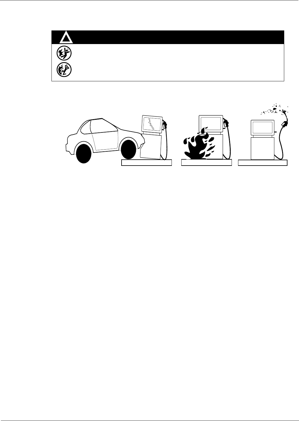
WARNING
Spilled fuels, accidents involving pumps/dispensers, or uncontrolled fuel flow create a
serious hazard.
Fire or explosion may result, causing serious injury or death.
Follow established emergency procedures.
DEF is non-flammable. However it can create a slip hazard. Clean up spills promptly.
!
Collision of a Vehicle with Unit Fire at Island Fuel Spill
The following actions are recommended regarding these hazards:
• Do not go near a fuel spill or allow anyone else in the area.
• Use station EMERGENCY CUTOFF immediately. Turn off all system circuit breakers to the island(s).
• Do not use console E-STOP, ALL STOP, and PUMP STOP to shut off power. These keys do not
remove AC power and do not always stop product flow.
• Take precautions to avoid igniting fuel. Do not allow starting of vehicles in the area. Do not allow
open flames, smoking or power tools in the area.
• Do not expose yourself to hazardous conditions such as fire, spilled fuel or exposed wiring.
• Call emergency numbers.

Page 2-4 MDE-3664B TRIND® Start-up, Service, and Parts Manual · June 2013
Important Safety Information
This page is intentionally left blank.

MDE-3664B TRIND® Start-up, Service, and Parts Manual · June 2013 Page 3-1
Full Systems Systems Overview
3 – Systems Overview
Full Systems
The Full System product is an option available as a retrofit kit or factory installed equipment
on The Advantage Series, Multi Product Dispenser (MPD-3), Encore, and Eclipse lines of fuel
dispensers. The TRIND device is connected to the CRIND through a gateway or serial
interface board. In this application TRIND is a software slave to the CRIND and the associated
POS controller/host. This means that a properly working TRIND system will look for and read
tags, but only when told to by the controller, through the CRIND application.
This system is to be installed in accordance with all Underwriters’ Laboratory (UL), Federal
Communications Commission (FCC), federal, state, and local regulations associated with it.
The following illustrations depict the system component used in the Original, The Advantage
Series, MPD-3, and Encore Full Systems.
Figure 3-1: Original Full System Block Diagram
Overhead Antenna Assembly
Side A
T20231-G1
LF Transmitter (134kHz Intentional
Radiator)
Q13579-01
Control Data
UHF Receiver Module
902 - 928 MHz
115 VAC
(FROM Dispenser
AC POWER
DISTRIBUTION)
RS-232 RS-232
Gateway Board
T20128 SERIAL DATA
to CRIND logic boards
(Dispenser Electronics)
J7 J8
J4
P187
P250
P185
22VDC,
5VDC, GND
5VDC,
GND
22VDC,
5VDC, GND
J6
J3
22VDC, 5VDC, GND
22VDC, 5VDC, GND
J5 J5
J2A J2B JA JB
LF TX
UHF RX Overhead Antenna Assembly
Side B
T20231-G1
UHF RX
LF TX
POWER REGULATING
Circuit Board
T20138-G1
P177P179P176
P175
P178
Light Board Assembly
(T20295, T20446)
on Dispenser Bezel Face
(Side A)
P181
P180,
P182
RS-232, Digital
Control and Light
Control Circuit
P180,
P182
P181
RS-232, Digital
Control and Light
Control Circuit
When overhead antennas are not part of
the product, Dummy Load R20526-G1
plugs into JA and JB. J2A and J2B are
left unconnected.
DATA CONTROL BOARD
Q13563-01 or -02
60VAC
Power Supply
R20600-G1
AC Power EMC Filter
Q10895-01
Micro-Reader
Q13551-01
(134 KHz
Intentional)
Micro-Reader
Q13551-01
(134 KHz
Intentional)
T20143
Bezel
Antenna
R20522-G2
Cable
T20143
Bezel
Antenna
R20522-G2
Cable
Light Board Assembly
(T20295, T20446)
on Dispenser Bezel Face
(Side B)
RS-232
LF TX/RX
LF TX/RX
RS-485
Page 3-2 MDE-3664B TRIND® Start-up, Service, and Parts Manual · June 2013
Systems Overview Full Systems
Figure 3-2: The Advantage Series Full System Block Diagram
Overhead Antenna Assembly
Side A
T20231-G1
LF Transmitter (134kHz Intentional
Radiator)
Q13579-01
Control Data
UHF Receiver Module
RI-RFM-HREA
902 - 928 MHz
115 VAC
(FROM Dispenser
AC POWER
DISTRIBUTION)
RS-232RS-232
Gateway Board
T20128SERIAL DATA
to CRIND logic boards
(Dispenser Electronics)
J7J8
J4
P187
P250
P185
22VDC,
5VDC, GND
5VDC,
GND
22VDC,
5VDC, GND
J6
J3
22VDC, 5VDC, GND
22VDC, 5VDC, GND
J5J5
J2AJ2BJAJB
Overhead Antenna Assembly
Side B
T20231-G1
Light Board Assembly
(T20601-GX or
M01560A00X)
on Dispenser Bezel Face
(Side A)
POWER REGULATING
Circuit Board
T20314-G1
P177
P179
P176
P175
P178
Light Board Assembly
(T20601-GX or
M01560A00X)
on Dispenser Bezel Face
(Side A)
P181
P182
RS-232, Digital
Control and Light
Control Circuit
P182
P181
RS-232, Digital
Control and Light
Control Circuit
M00878A002
M00878A002
M00878A002
Cable
Cable
Cable
When overhead antennas are not part of
the product, Dummy Load R20526-G1
plugs into JA and JB. J2A and J2B are
left unconnected.
R20773-G2, door cable,
provides power and RS232
communications
R20773-G2, door cable,
provides power and RS232
communications
X is color of LEDs
DATA CONTROL BOARD
Q13563-02 or -04
5 MHz (UHF Clock - selected
by jumper)
10 MHz (Local Clock - not
selected for this application)
24 VAC
Power Supply
AC PowerEMC
Filter
Q10895-01
Micro-Reader
Q13551-01
(134 KHz
Intentional)
Micro-Reader
Q13551-01
(134 KHz
Intentional)
M00878A002
Cable
T20524
Bezel
Antenna
R20522-G2
Cable
T20524
Bezel
Antenna
R20522-G2
Cable
RS-232
LF TX/RX
LF TX/RX
UHF RCVUHF RCV
LF TX
LF TX
RS-485

MDE-3664B TRIND® Start-up, Service, and Parts Manual · June 2013 Page 3-3
Full Systems Systems Overview
Figure 3-3: Encore Full System Block Diagram
Overhead Antenna Assembly
Side A
LF Transmitter (134kHz Intentional
Radiator)
Q13579-01
Control Data
UHF Receiver Module
RI-RFM-HRUA
902 - 928 MHz
115 VAC
(FROM Dispenser
AC POWER
DISTRIBUTION)
RS-232
RS-232
Gateway Board
T20128
SERIAL DATA
to CRIND logic boards
(Dispenser Electronics)
P187
P250
P185
22VDC, 5VDC,
GND
5VDC,
GND
22VDC,
5VDC, GND
22VDC, 5VDC, GND
22VDC, 5VDC, GND
J2A J2B
LF Transmit Antenna
UHF Receive Antenna
Overhead Antenna Assembly
Side B
LF Transmit Antenna
UHF Receive Antenna
Light Board Assembly
M01218A00X
on Dispenser Bezel Face
(Side A)
POWER REGULATING
Circuit Board
T20314-G1
P177P179P176
P175
P178
Light Board Assembly
M01218A00X
on Dispenser Bezel Face
(Side A)
P182
RS-232, Digital
Control and Light
Control Circuit
P182
RS-232, Digital
Control and Light
Control Circuit
J1A
J3A
J3B
J1B
M00878A001
M00878A001
M00878A001
Cable
Cable
Cable
Tuner Board T20579
Tuner Board T20579
Q13851-01 Q13851-01
WO3889 WO3889
When overhead antennas are not part of
the product, Dummy Load R20526-G1
plugs into JA and JB. J2A and J2B are
left unconnected.
R20773-G2, door cable,
provides power and RS232
communications
R20773-G2, door cable,
provides power and RS232
communications
X is color of LEDs
DATA CONTROL BOARD
Q13563-02 or -04
5 MHz (UHF Clock - selected
by jumper)
10 MHz (Local Clock - not
selected for this application)
24 VAC
Power Supply
AC Power EMC Filter
Q10895-01
Micro-Reader
Q13551-01
(134 KHz
Intentional)
Micro-Reader
Q13551-01
(134 KHz
Intentional)
M00878A001
Cable
Encore
Antenna
(on board
Encore
keytag
Antenna
(on board
RS-232
RS-485
UHF RCVUHF RCV
LF TX LF TX

Page 3-4 MDE-3664B TRIND® Start-up, Service, and Parts Manual · June 2013
Systems Overview Hand-held Only Tag System Overview
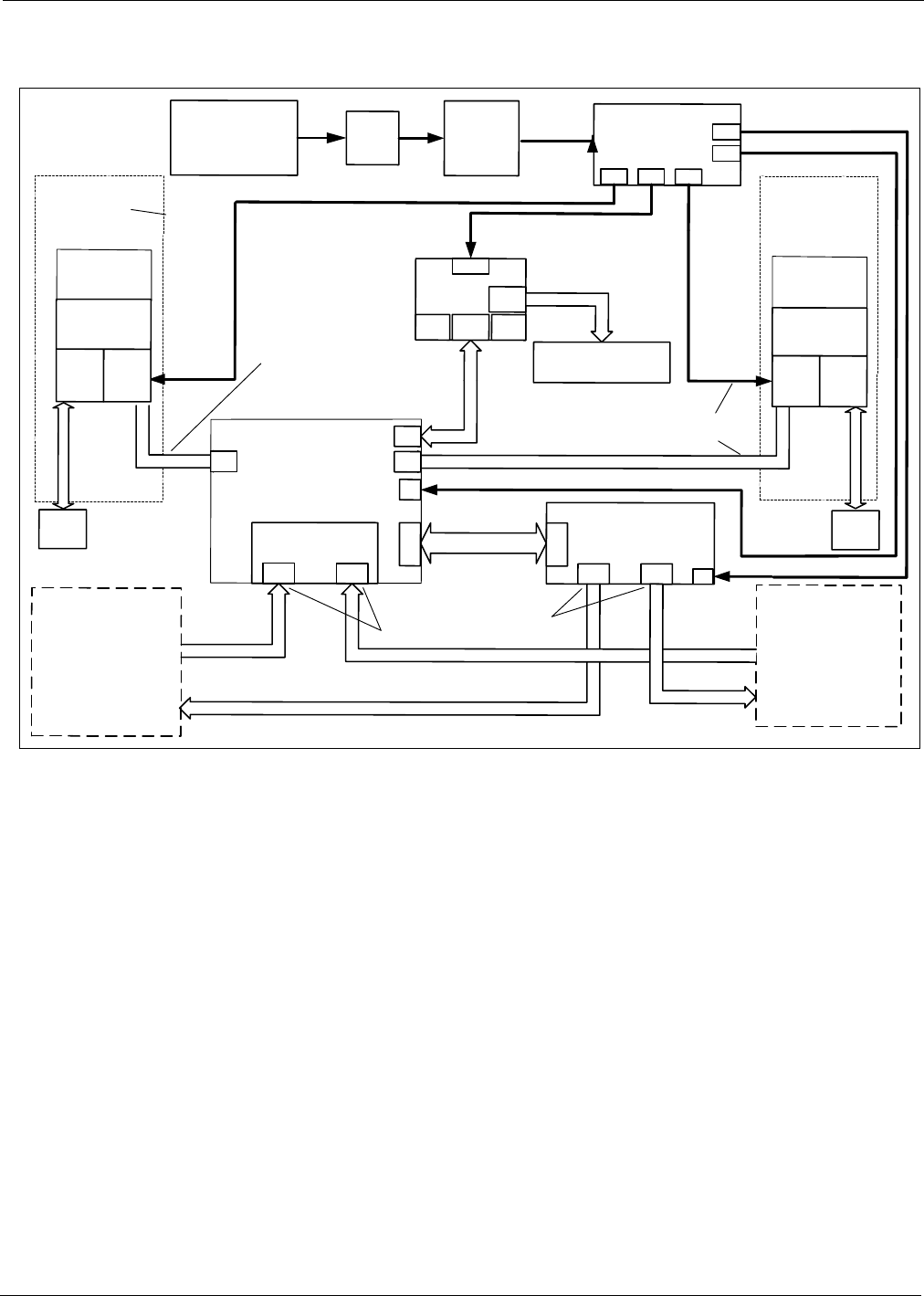
Hand-held Only Tag System Overview
This product is an option available as a retrofit kit or factory installed equipment in The
Advantage Series, MPD-3, and Encore lines of fuel dispensers. The TRIND Enhanced
Gateway Board (T20678) manages RFID processing and provides simple, generic event
messages to the pump electronics via Transistor-Transistor Logic (TTL). In this application,
TRIND is a software slave to the CRIND and the associated POS controller/host. This means
that a properly working LF TRIND system will look for and read tags, but only when told to
by the controller, through the CRIND application.
This system is to be installed in accordance with all UL, FCC, federal, state, and local
regulations. The following block diagram depicts the components for the Hand-held Only Tag
System.
Figure 3-4: Hand-held Only Tag System Block Diagram
MDE-3664B TRIND® Start-up, Service, and Parts Manual · June 2013 Page 4-1
Card Cage Assemblies Major Hardware Components
4 – Major Hardware Components
Card Cage Assemblies
There are four main Card Cage versions used for the TRIND system. These four Card Cages
are T20229-G1, T20606-G2, T20606-G3, and T20606-G5. The T20229 Card Cage is no
longer available and is discussed in this manual simply for the service and support of the
installed base. There are other G-levels of the T20606 Card Cage, but these are variations of
the -G2 and -G3. Therefore, being familiar with these base Card Cages and their parts will
provide the technician with valuable information in servicing the other G-levels, if
encountered.
Note: Many parts look similar in the T20229 and T20606 Card Cages, but they are not the
same. Always replace the removed part with the same part number or risk voiding the
UL listings, FCC certifications, warranty, if applicable.
T20229-G1 Card Cage Assembly
The T20229 Card Cage was the installed Card Cage for the original Mobil Speedpass
program. With a few cable changes, this Card Cage can be replaced by the T20606-G2 Card
Cage, which contains the new Multi-port Data Control Board (DCB) from Texas Instruments.
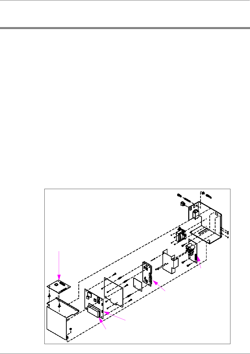
Figure 4-1: T20229-G1 Card Cage Assembly
Power Supply
PCB
UHF Receiver Assembly on DCB
DCB
Gateway Board
UHF Receiver Assembly on DCB

Major Hardware Components Card Cage Assemblies
Page 4-2 MDE-3664B TRIND® Start-up, Service, and Parts Manual · June 2013
T20229-G1 Card Cage Assembly Parts List
Following table lists the T20229-G1 Card Cage Assembly parts:
Item Description Part Number
1Power Supply PCB T20138-G1
2Transmitter PCB Assembly Q13579-01
3DCB Q13563-01
4UHF Receiver Assembly on DCB Q13564-01
5Gateway Board T20128-G1
T20606-G2 Card Cage Assembly
T20606-G2 Card Cage is the updated version of the T20229-G1 Card Cage. It features a
multi-port DCB, LF Transmitter, and a high-gain UHF receiver. It also has a Card Cage
Harness, which reduces the number of field connections that must be made (compared to
T20229). This Card Cage comes ready to mount in an Encore unit, and also easily modified to
work in Eclipse, The Advantage Series, and MPD-3 units.
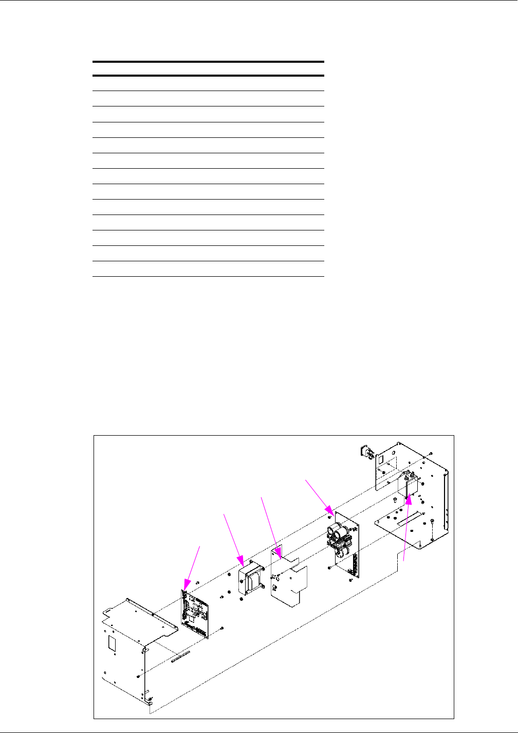
Figure 4-2: T20606-G2 Card Cage Assembly
TRIND Gateway PCB
24 VAC Transformer
Recessed Power Receptacle 10 A EMI Filter
TRIND PCB Shield Bracket
Low Frequency
Transmitter Module
PCB Insulator Board
Radio PCB Shield
Multi-port DCB
TRIND PCB Bracket
Circuit Board Support
Regulator
PCB Shield
Regulator
PCB
MDE-3664B TRIND® Start-up, Service, and Parts Manual · June 2013 Page 4-3
Card Cage Assemblies Major Hardware Components
T20606-G2 Card Cage Assembly Parts List
Following table lists the T20606-G2 Card Cage Assembly parts:
Item Description Part Number
1TRIND Gateway PCB T20128-G3
2Circuit Board Support Q10651-16
3TRIND PCB Bracket M00624A001
4Multi-port DCB Q13563-04
5Radio PCB Shield R20545-G1
6PCB Insulator Board R20590-01
7Low Frequency Transmitter Module Q13579-01
824 VAC Transformer R20719-G1
9Recessed Power Receptacle R20206-G14
10 10 A EMI Filter Q10895-01
11 TRIND PCB Shield Bracket M00621A001
12 Regulator PCB Shield T20198-01
13 Regulator PCB T20314-G1
T20606-G3 Card Cage Assembly
T20606-G3 Card Cage supports “keytag only” operation and features an Enhanced Gateway
Board, which serves as the local controller for the RF modules (taking the place of the DCB)
and the protocol handler for payment messaging (to CRIND or other Host Controller device).
This Card Cage comes ready to mount in Encore, The Advantage Series, Eclipse and MPD-3,
with no modifications required.
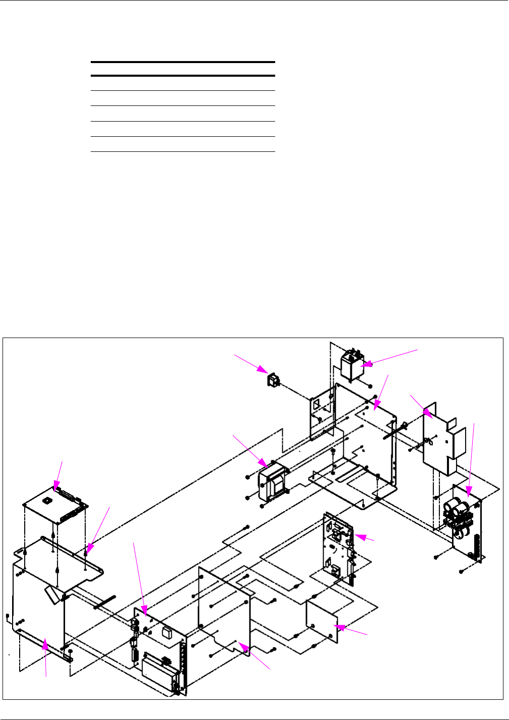
Figure 4-3: T20606-G3 Card Cage Assembly
Regulator PCB
Enhanced Gateway PCB
Shield, Regulator, PCB
Filter, EMI,
10 A
Transformer, 24 VAC
Major Hardware Components Card Cage Assemblies
Page 4-4 MDE-3664B TRIND® Start-up, Service, and Parts Manual · June 2013
T20606-G3 Card Cage Assembly Parts List
Following table lists the T20606-G3 Card Cage Assembly parts:
Item Description Part Number
1Regulator PCB T20314-G1
2Regulator PCB Shield T20198-01
324 VAC Transformer R20719-G1
4Enhanced Gateway PCB T20678-G1
510 A EMI Filter Q10895-01
T20606-G5 Card Cage Assembly
T20606-G5 Card Cage is a variation of the T20606-G2 Card Cage required for many
international “full system” TRIND applications (Europe and southeast Asia). It features a
European Telecommunications Standards Institute (ETSI) DCB, LF Transmitter, and a high-
gain UHF receiver. It also has a Card Cage Harness, which reduces the number of field
connections that must be made (compared to the original T20229). This Card Cage comes
ready to mount in an Encore unit, and is easily modified to also work in Eclipse, The
Advantage Series, and MPD-3 units.
Figure 4-4: T20606-G5 Card Cage Assembly
TRIND Gateway PCB
24 VAC Transformer
Recessed Power Receptacle 10 A EMI Filter
TRIND PCB Shield Bracket
Low Frequency
Transmitter
Module
PCB Insulator Board
Radio PCB Shield
ETSI DCB
TRIND PCB Bracket
Circuit Board
Support
Regulator PCB Shield
Regulator
PCB

MDE-3664B TRIND® Start-up, Service, and Parts Manual · June 2013 Page 4-5
Card Cage Assemblies Major Hardware Components
T20606-G5 Card Cage Assembly Parts List
Following table lists the T20606-G5 Card Cage Assembly parts:
Item Description Part Number
1TRIND Gateway PCB T20128-G3
2Circuit Board Support Q10651-16
3TRIND PCB Bracket M00624A001
4ETSI DCB Q13563-07
5Radio PCB Shield R20545-G1
6PCB Insulator Board R20590-01
7Low Frequency Transmitter Module Q13579-01
824 VAC Transformer R20719-G1
9Recessed Power Receptacle R20206-G14
10 10 A EMI Filter Q10895-01
11 TRIND PCB Shield Bracket M00621A001
12 Regulator PCB Shield T20198-01
13 Regulator PCB T20314-G1
Disassembly and Installation for MPD-3 Units with SID Displays
In some older installations, a screw and two nuts were installed under the Card Cage on Side B
of a unit. This causes the installed Card Cage to rest at an angle, higher on Side B. This
hardware must remain in place to prevent contact between the Card Cage and the SID boards
when the bezel door is closed.
Disassembly and Installation for All MPD-3 Units
In field retrofits, the TRIND units top (center) screw from the Card Cage was removed, and
replaced by tie-wraps at either side after the Card Cage was installed in the cabinet. The Card
Cage can only be removed or installed when separated into two pieces (see Figure 4-5).
Figure 4-5: Screw and Tie-wrap Locations
Screw
Tie-wraps
Tie-wraps
Major Hardware Components Card Cage Assemblies
Page 4-6 MDE-3664B TRIND® Start-up, Service, and Parts Manual · June 2013
AC EMI Line Filter (Q10895)
AC Electromagnetic Interference (EMI) Line Filter, is a Corcom dual T section RFI power
line filter. These filters are well suited for low impedance loads where noisy RFI environments
are present. They control pulsed, continuous and/or intermittent interference, insuring
protection of the TRIND equipment from power line noise in addition to protecting the line
from equipment noise.
R20600 and R20719 Transformers
R20600-G1 Transformer is used in the T20229-G2 Card Cage Assembly. R20719-G1
Transformer is used in the T20606-G2 LF/UHF Full System, and Enhanced Gateway System
Card Cages. Each transformer performs step down of 120 VAC to a usable level for the RFID
Power Supply. The R20600 steps 120 VAC down to 60 VAC, which is used by the T20138-G1
Power Supply Board. The R20719 steps 120 VAC down to 24 VAC, which is used by the
T20314-G1 Power Supply Board.
T20138 and T20314 Power Supply Boards
T20138-G1 Power Supply Board is used in the T20229-G1 Full System Card Cage Assembly.
T20314-G1 Power Supply Board is used in T20606 line of Card Cages. The supplies take the
output of their respective AC to AC transformers and make the proper Direct Current (DC)
voltages for use by the TRIND system components. Both supplies utilize a gate-driven Metal-
oxide-semiconductor Field-effect Transistor [MOSFET (for +22 VDC)] and a buck switched
mode power supply (for +5 VDC). Both supplies monitor the current on the output to turn off
the gate drive, rather than fail permanently, should one of the TRIND system components
develop a voltage problem. This arrangement allows for any of the outputs to be shorted
directly to ground with out harming the power supply because it turns itself off until the
problem is discovered and removed, and AC power is cycled.
T20138 Power Supply Board
This board has jump-jack locations to set the dither sync (refer to “Glossary” on page 4-1)
address for the TRIND unit, with a 10-position ribbon cable (at P173) that goes to the DCB
(J6). These addresses only matter to the site itself, not the pump or CRIND.
Figure 4-6: T20138 Power Supply Board
5 V
GND
22 V
GND GND
5 V 22 V
GND
Note: P176, P177, and P178 are identical.
JP1 through JP4:
must be unique
address for each
dispenser at site
22 V 5 V
5 V

MDE-3664B TRIND® Start-up, Service, and Parts Manual · June 2013 Page 4-7
Card Cage Assemblies Major Hardware Components
T20314 Power Supply Board
This board must be used in conjunction with the R20719 Transformer.
Figure 4-7: T20314 Power Supply Board
5 V
GND
22 V
GND GND
5 V 22 V
GND
Note: P176, P177, and P178 are identical.
22 V
5 V
Q13563 Data Control Boards
Q13563-01 and Q13563-02 Data Control Boards are used in T20229-G1 Full System Card
Cage assembly. The Q13563-04 Board is used in T20606-G2 Full System Card Cage
assembly. These DCBs handle tag reader control and pass the system status, and tag data up to
the Gateway Board. The earlier versions (-01, -02) of this board made use of jump jacks on the
Power Supply Board for dither sync addressing, subsequent versions (-04 and above) contain
Dual Inline Package (DIP) switches for this site-specific addressing.
Figure 4-8: Q13563-01 and Q13563-02 DCBs
CR5 - pulsing (heartbeat)
CR11 - RS485 - TX
CR10 - RS485 - RX
Note: In normal operation CR10-RS485-RX and CR11 - RS485 - TX will be in sync.
CR3 - 12 V
CR2 - 5 V
On Continuously

Major Hardware Components Card Cage Assemblies
Page 4-8 MDE-3664B TRIND® Start-up, Service, and Parts Manual · June 2013
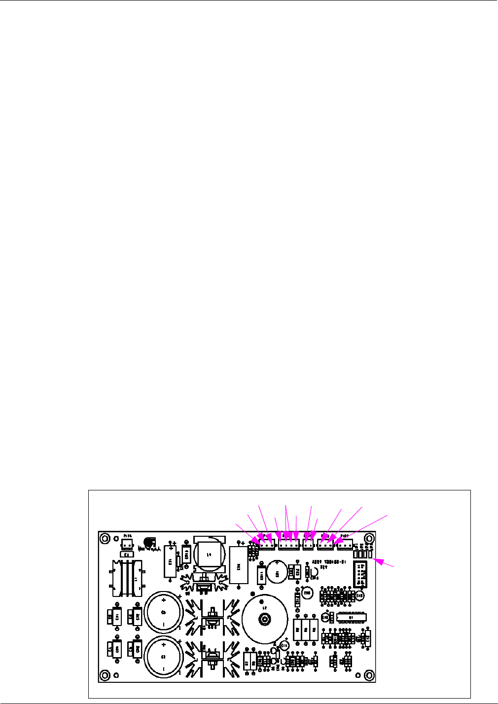
Figure 4-9: Q13563-04 DCBs and Above
Heart Beat
RS-485 TX
Read ANT 1
Read ANT 3
Bezel I/0 Error
Bit Restore
Bit Fail
RS-485 RX
+12 VDC
+5 VDC
UHF Receiver Board (Q13564)
Mounted on the DCB, the UHF Receiver Board receives 12 VDC from the DCB. The board
also receives information from UHF antennas over J2A or J2B and processes the UHF signal.
This receiver has to comply with FCC and in-country communication protocols such as ETSI.
For this application the ETSI protocol is required for Asia and Europe.
Figure 4-10: UHF Receiver Board

MDE-3664B TRIND® Start-up, Service, and Parts Manual · June 2013 Page 4-9
Card Cage Assemblies Major Hardware Components
The UHF Receiver Module contained on the DCB, handles the uplink signal from the vehicle
tag. It receives the signal from the vehicle tag that transmits data on a UHF carrier, and down
converts and demodulates this signal to binary data. The UHF Receiver also includes the
master oscillator for the DCB and provides all clock signals for other elements within the DCB
to keep signal paths as short as possible. The UHF receive antenna connections are made via
Sub Miniature A (SMA) connectors on Antenna Cables (M00878A001, M00878A002, and
Q13578-01).
Q13579 Transmitter Board
Q13579-01 Transmitter Board is used in the T20229-G1 and T20606-G2 Full System Card
Cages. The Transmitter Board is actually a three-board assembly containing two identical
transmitter modules (one each for Sides A and B) mounted on a larger Printed Circuit Board
(PCB). The Q13579-01 Transmitter Board contains all the functions to activate vehicle tags.
The module includes a carrier board onto which are mounted two transmit-only Radio
Frequency Modules (RFMs), the power supply, oscillator and tuning connector for the RFMs,
logic circuitry to determine RFM selection, power level adjustment capability, and a pulse
width modulation circuit. This board receives +22 VDC, +5 VDC and GND through J6. If this
board is replaced, overhead antennas need to be retuned. The transmitter provides an
approximate 134 kHz signal for TRIND antennas, through JA for Side A and JB for Side B of
the dispenser.
Figure 4-11: Transmitter Board
Major Hardware Components Card Cage Assemblies
Page 4-10 MDE-3664B TRIND® Start-up, Service, and Parts Manual · June 2013
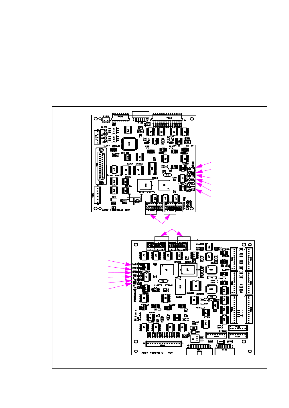
T20128 and T20678 Gateway Boards
T20128-GX Gateway Board is used in the Full System T20229-G1 and T20606-G2 Card
Cages. The T20678 Gateway Board is used in the T20606-G3 Card Cage. These boards
manage events and message processing to/from the Controller (CRIND, POS, host controller)
and the readers. On the full systems, the Gateway Board manages RFID processing through
the DCB (which communicates with the vehicle tags via overhead antennas and with
hand-held tags via bezel readers). On Enhanced Gateway systems, the board manages
hand-held RFID processing through direct communication with the bezel readers.
Figure 4-12: Gateway Boards
TX = To Side A CRIND
RX = From Side B CRIND
PWR = 5 V
Must match corresponding CRIND address
CPU = Software Running
CPU = Software Running
PWR = 5 V
RX = From Side A CRIND
TX = To Side A CRIND
RX = From Side B CRIND
TX = To Side B CRIND
TX = To Side A CRIND
T20128-GX
T20678-GX
MDE-3664B TRIND® Start-up, Service, and Parts Manual · June 2013 Page 4-11
Card Cage Assemblies Major Hardware Components
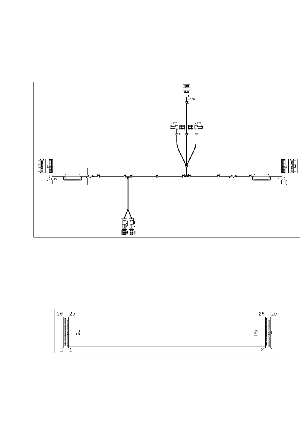
Card Cage Cable Harness (T20662-G2)
The Card Cage Cable Harness Assembly provides power and data distribution to/from the
Card Cage and the Light/Micro Reader Printed Circuit Assembly (PCA). It comes already
installed on the T20606-G2 Card Cage from the factory.
Figure 4-13: Card Cage Cable Harness
Full System TRIND Transmitter Cable (R20520-G1)
The Transmitter Cable is a 26-pin connector cable that is routed between the Low Frequency
Transmitter Board (Q13579) and DCB (Q13563).
Figure 4-14: Transmitter Cable

Major Hardware Components Card Cage Assemblies
Page 4-12 MDE-3664B TRIND® Start-up, Service, and Parts Manual · June 2013
Full System TRIND RS-485 Communication Cable (R20525-G1)
The Communication Cable is a 4-pin and 5-pin connector cable that is connected between the
Q13563 DCB and T20128 Gateway Board.
Figure 4-15: RS-485 Communication Cable
To Gateway Board To Data Control Board
Full System TRIND Power Supply Cables (R20763-GX)
The Power Supply Cables connect the LF Transmitter (-G1), the DCB (-G2), and the
Gateway (-G3) Boards to the T20314 Power Supply.
Figure 4-16: Power Supply Cables
R20763-G1
R20763-G2
R20763-G3

MDE-3664B TRIND® Start-up, Service, and Parts Manual · June 2013 Page 4-13
Card Cage Assemblies Major Hardware Components
Hand-held TRIND System Ribbon Cable (M00507)
The Ribbon Cable is a 14-pin cable routed between T12678 Gateway Board and R20773
TRIND Option Door Data and Power Cable. The R20773 Cable leads to the Light/Micro
Reader Board (T20601). The -A001 Cable is used for Side A (or Side 1 based on the
dispenser). The -A002 Cable is used for Side B (or Side 2 based on the dispenser).
Figure 4-17: Hand-held TRIND System Ribbon Cable
Hand-held TRIND System Power Cable (M01366)
The TRIND Power Cable is a three-wire cable routed between the T20314 Power Supply
Assembly and the T20678 Gateway Board.
Figure 4-18: Hand-held TRIND System Power Cable
Major Hardware Components TRIND Overhead Antennas
Page 4-14 MDE-3664B TRIND® Start-up, Service, and Parts Manual · June 2013
TRIND Overhead Antennas
Full System TRIND has six antennas, four active and two passive. The active antennas can
further be divided as transmit only (overhead antennas), and transmit and receive [option
door/Customer Interface Module (CIM) door antennas]. All four operate in the LF band at
134.2 kHz. The two passive antennas receive in the UHF Band at 902 MHz (in the US) and at
868 MHz (Asia and Europe), and are used in conjunction with the overhead antennas to utilize
the car tags. There are two basic variations of the full system TRIND. The fundamental
differences are based on the Card Cage and the overhead antennas used. The antennas can be
divided into two sections, the original Mobil antennas (no longer available) and the
single-loop antennas, which are currently being shipped with full system TRIND.
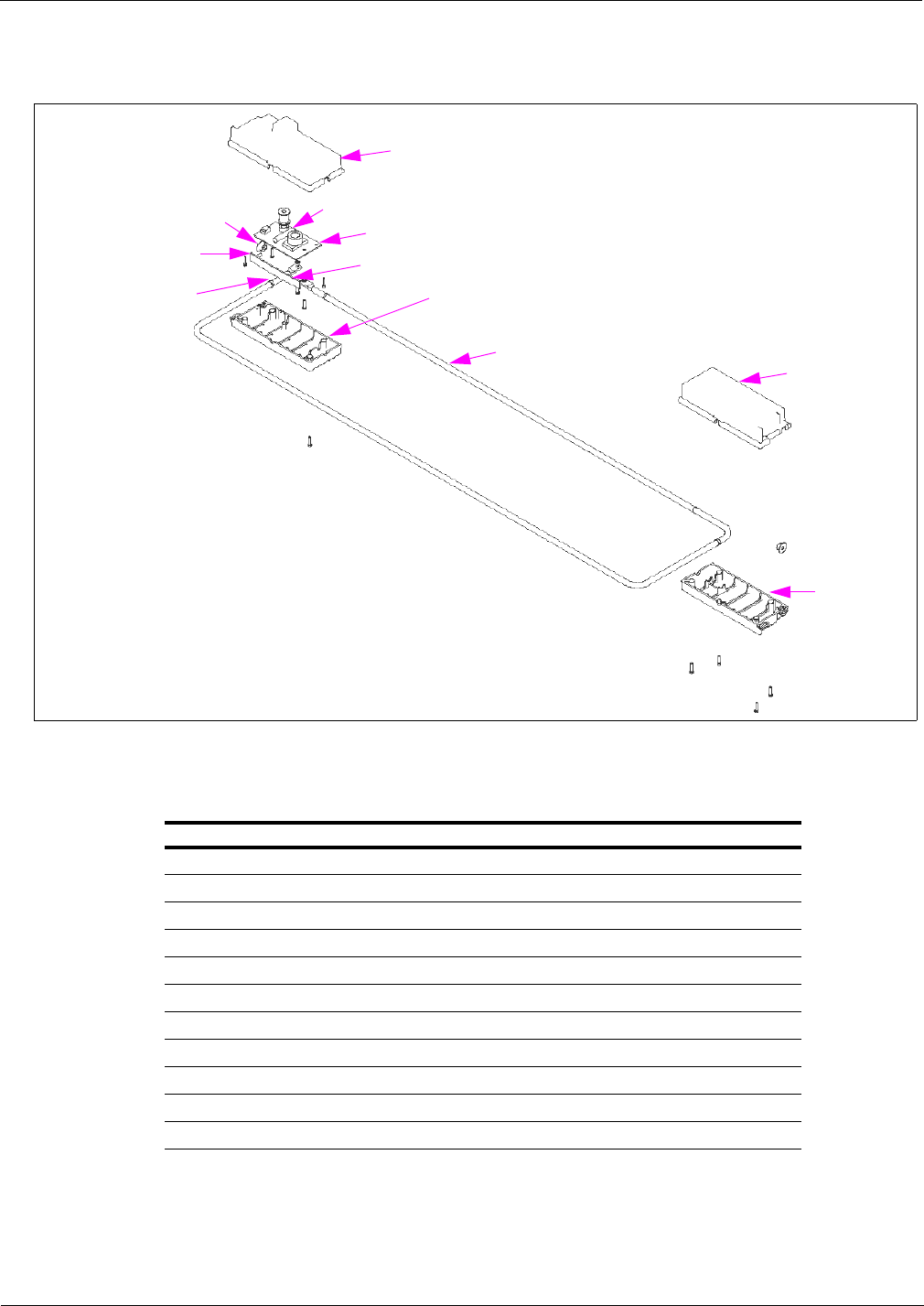
Mobil Overhead Antenna Assembly (T20231)
The Mobil overhead antenna assembly consists of a multiple loop (47 uH) coil for LF
transmission, a tuning board, and sheet metal slot antenna for UHF receive. This assembly is
no longer available, but is still a part of the installed base at Mobil Stations. These antennas
have been replaced by the T20632 family of Overhead Antennas.
Figure 4-19: Mobil Overhead Antenna Assembly
Tuner Gasket
Tuner Cover
Tuning Board
Molded Antenna
902.858 MHz HF Antenna,
868.4 MHz HF Antenna
Mobil Overhead Antenna Assembly
Following table lists the Mobil Overhead Antenna Assembly parts:
Item Description Part Number
1902.858 MHz HF Antenna Q13580-01
2868.4 MHz HF Antenna Q13580-02
3Molded Antenna Q13582-01
4Tuning Board Q13582-02
5Tuner Gasket Q13582-04
6Tuner Cover Q13582-03
MDE-3664B TRIND® Start-up, Service, and Parts Manual · June 2013 Page 4-15
TRIND Overhead Antennas Major Hardware Components
Figure 4-20: Mobil Overhead Antenna Bracket Assemblies and Hardware
Bracket, Universal
Antenna
Conduit, Flexible Black Plastic
Connector, Tube Fitting
Over Head Antenna Cables 1/4-20 Nut, Black
1/4-20 Bolt X 4” Black
Antenna Assembly
Screw, 10-32 Black
Bracket, Antenna Mounting
Antenna Top Cover
Note: For units with logo display cabinets, universal antenna brackets are installed with flat side up.

Major Hardware Components TRIND Overhead Antennas
Page 4-16 MDE-3664B TRIND® Start-up, Service, and Parts Manual · June 2013
Mobil Overhead Antenna Bracket Assemblies (T20231) and Hardware for
The Advantage Series
Following table lists the Mobil Overhead Antenna Bracket Assemblies and hardware for The
Advantage Series:
Item Description Wide Frame
Single-sided Wide Frame
Double-sided Narrow Frame
Single-sided Narrow Frame
Double-sided
1Antenna Top Cover T20213-01 T20213-01 T20215-01 T20215-01
2Bracket, Universal Antenna T20212-01 T20212-01 T20212-01 T20212-01
3Bracket, Antenna Mounting T20211-01 T20211-01 T20211-01 T20211-01
3a Bracket, Antenna Mounting (see note) T20211-02 -T20211-02 -
4Screw, 10-32 Black K85736-45 K85736-45 K85736-45 K85736-45
5Antenna Assembly T20231-G1 T20231-G1 T20231-G1 T20231-G1
61/4-20 Bolt x 4” Black K01914-70 K01914-70 K01914-70 K01914-70
71/4-20 Nut, Black Q11890-08 Q11890-08 Q11890-08 Q11890-08
8Over Head Antenna Cables R20509-G1
Q13578-01
R20509-G1
Q13578-01
R20509-G1
Q13578-01
R20509-G1
Q13578-01
9Connector, Tube Fitting Q13591-01 Q13591-01 Q13591-01 Q13591-01
10 Conduit, Flexible Black Plastic Q13592-02 Q13592-02 Q13592-02 Q13592-02
Note: Not shown on page 4-16, single-sided antenna bracket has no antenna mounting arms.
Mobil Overhead Antenna Bracket Assemblies and Hardware for MPD-3
Following table lists the Mobil Overhead Antenna Bracket Assemblies and hardware for
MPD-3:
Item Description PMI Bezel
Single-sided PMI Bezel
Double-sided Mack Bezel
Single-sided Mack Bezel
Double-sided
1Antenna Top Cover T20214-01 T20214-01 T20214-01 T20214-01
2Bracket, Universal Antenna T20212-01 T20212-01 T20212-01 T20212-01
3Bracket, Antenna Mounting T20211-01 T20211-01 T20211-01 T20211-01
3a Bracket, Antenna Mounting (see note) T20211-02 -T20211-02 -
4Screw, 10-32 Black K85736-45 K85736-45 K85736-45 K85736-45
5Antenna Assembly T20231-G1 T20231-G1 T20231-G1 T20231-G1
61/4-20 Bolt x 4” Black K01914-70 K01914-70 K01914-70 K01914-70
71/4-20 Nut, Black Q11890-08 Q11890-08 Q11890-08 Q11890-08
8Over Head Antenna Cables R20509-G1
Q13578-01
R20509-G1
Q13578-01
R20509-G1
Q13578-01
R20509-G1
Q13578-01
9Connector, Tube Fitting Q13591-01 Q13591-01 Q13591-01 Q13591-01
10 Conduit, Flexible Black Plastic Q13592-02 Q13592-02 Q13592-02 Q13592-02
Note: Not shown on page 4-16, single-sided antenna bracket has no antenna mounting arms.

MDE-3664B TRIND® Start-up, Service, and Parts Manual · June 2013 Page 4-17
TRIND Overhead Antennas Major Hardware Components
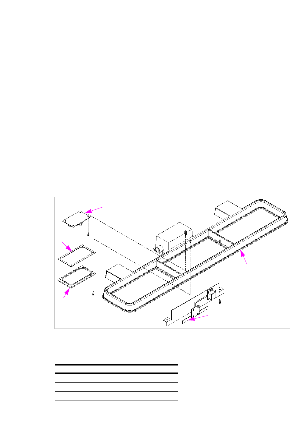
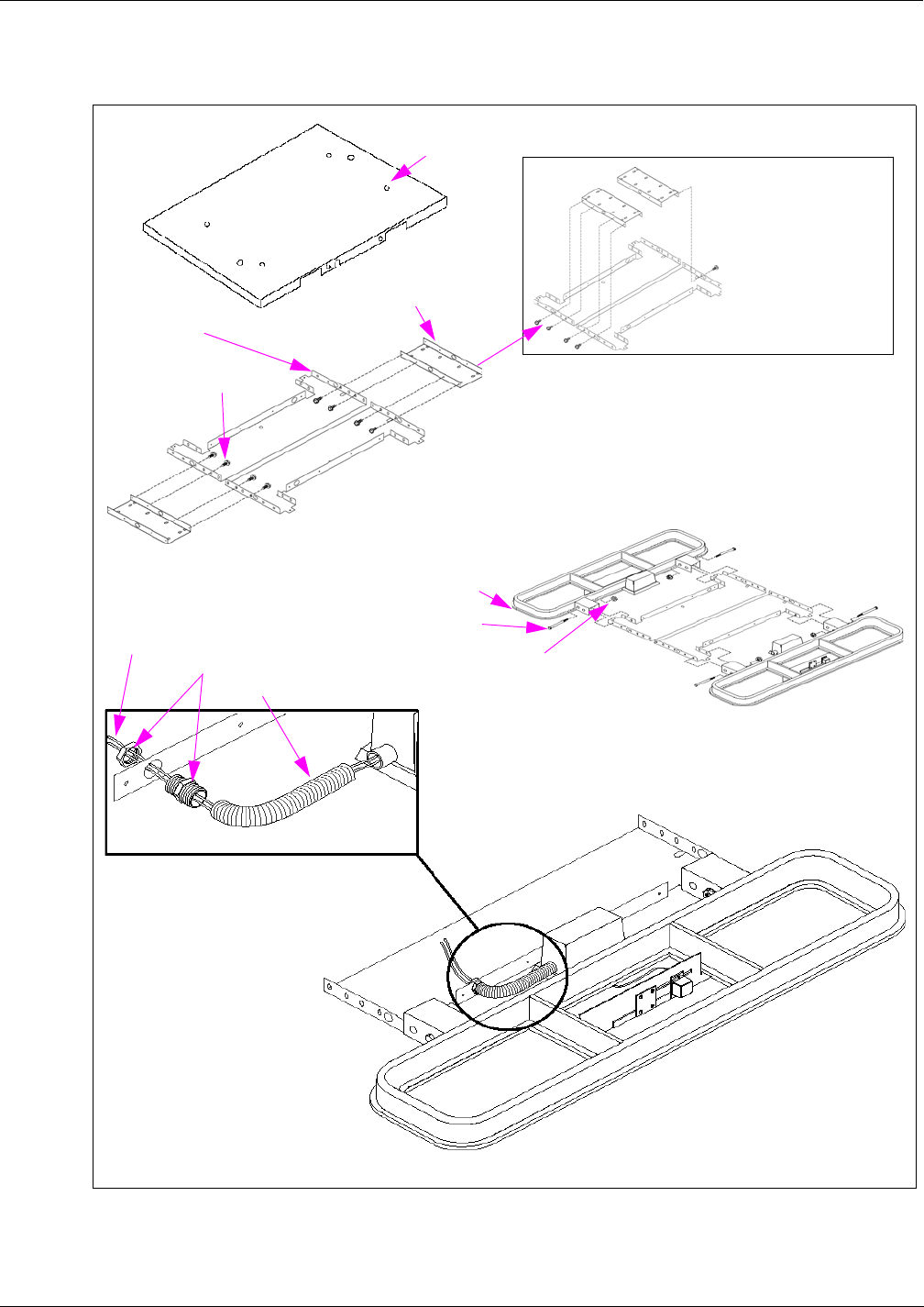
Single-loop Overhead Antenna Assembly (T20632)
The Single-loop Overhead Antenna Assemblies (T20632-GX) are made up from a single turn
(loop) antenna; a high-efficiency tuning board, and a UHF receive antenna. These parts are all
mounted in a molded polycarbonate set of boxes and then mounted with brackets on top of the
dispenser. These parts are discussed in further in the following sections.
Note: There are eight different “G” levels of this antenna assembly, due to the different widths
and heights of the dispensers.
T20632 “G” Level Dispenser Antenna is used
G1/G5 Advantage Wide Frame and MPD-3
G2/G6 Advantage Narrow Frame
G3/G7 Encore
G4/G8 Advantage Wide Frame with Exxon® Light Box
SMA connections should be treated with care and not overtightened. The
maximum torque rating on these connectors is usually measured in inch pounds
Too severe a turn or bend in the cable may damage the center conductor or
compromise the shield/drain portion of the cable.
This can result in an observance of intermittent reads or other problems. The poor
performance will in turn generate a premature field service call. Replacing this
cable is labor intensive after the system is installed the first time.
Turns or bends in co-axial cable must be gradual loops, no sharper than a 1-inch
radius (2-inch diameter).
CAUTION
CAUTION
It is critical that the proper tool is used when tuning the overhead antennas on
TRIND systems. Only the Q13631-02 [part of Authorized Service Contractor (ASC)
Tool Kit K94577-01] plastic tuning tool (or similar plastic 0.10-inch hex tool) should
be used for tuning overhead antennas.
Using a metal screwdriver or Allen® wrench has two negative effects. First, a
proper tuning is impossible as the metal of the tool used changes the properties of
the variable inductor used for tuning. Second, the ferrite slug used in the variable
inductor is extremely brittle and is broken or stripped easily by metal tools,
preventing the proper tuning of the antenna.
If the antenna is not properly tuned the read range can be significantly reduced.
Major Hardware Components TRIND Overhead Antennas
Page 4-18 MDE-3664B TRIND® Start-up, Service, and Parts Manual · June 2013
Figure 4-21: Single-loop Overhead Antenna Assembly
Top Left Antenna Box
Lock Washer
Antenna Tuner PCA
Screw Thread Form # 6-19
Bottom Left Antenna Box
Antenna
Bottom Right
Antenna Box
Top Right Antenna
Box
Hex Nut
UHF Receiver Antenna
Neoprene Adhesive
Tape
Single-loop Overhead Antenna Assembly (Domestic)
Following table lists the Single-loop Overhead Antenna Assembly (Domestic) parts:
Item Description T20632-G1 T20632-G2 T20632-G3 T20632-G4
1Bottom Right Antenna Box T20615-04 T20615-04 T20615-04 T20615-04
2Top Right Antenna Box T20615-02 T20615-02 T20615-02 T20615-02
3Antenna W03889-01 W03889-02 W03889-03 W03889-04
4Bottom Left Antenna Box T20615-03 T20615-03 T20615-03 T20615-03
5Screw Thread Form # 6-19 Q12011-17 Q12011-17 Q12011-17 Q12011-17
6Antenna Tuner PCA T20579-G1 T20579-G2 T20579-G3 T20579-G4
7Lock Washer K46212 K46212 K46212 K46212
8Top Left Antenna Box T20615-01 T20615-01 T20615-01 T20615-01
9Hex Nut Q11890-04 Q11890-04 Q11890-04 Q11890-04
10 UHF Receiver Antenna Q13851-01 Q13851-01 Q13851-01 Q13851-01
11 Neoprene Adhesive Tape Q11899-12 Q11899-12 Q11899-12 Q11899-12

MDE-3664B TRIND® Start-up, Service, and Parts Manual · June 2013 Page 4-19
TRIND Overhead Antennas Major Hardware Components
Single-loop Overhead Antenna Assembly (International)
Following table lists the Single-loop Overhead Antenna Assembly (International) parts:
Item Description T20632-G5 T20632-G6 T20632-G7 T20632-G8
1Bottom Right Antenna Box T20615-04 T20615-04 T20615-04 T20615-04
2Top Right Antenna Box T20615-02 T20615-02 T20615-02 T20615-02
3Antenna W03889-01 W03889-02 W03889-03 W03889-04
4Bottom Left Antenna Box T20615-03 T20615-03 T20615-03 T20615-03
5Screw Thread Form # 6-19 Q12011-17 Q12011-17 Q12011-17 Q12011-17
6Antenna Tuner PCA T20579-G1 T20579-G2 T20579-G3 T20579-G4
7Lock Washer K46212 K46212 K46212 K46212
8Top Left Antenna Box T20615-01 T20615-01 T20615-01 T20615-01
9Hex Nut Q11890-04 Q11890-04 Q11890-04 Q11890-04
10 UHF Receiver Antenna Q13851-02 Q13851-02 Q13851-02 Q13851-02
11 Neoprene Adhesive Tape Q11899-12 Q11899-12 Q11899-12 Q11899-12
Figure 4-22: Single-loop Antenna Brackets and Hardware
Bottom Right Antenna Box
Antenna
Screw Thread
Form # 6-19
Screw Thread Form # 6-19
Antenna Tuner PCA
Antenna Tuner PCA
Antenna Tuner PCA
Antenna Tuner PCA
Top Right
Antenna Box
Bottom Left
Antenna Box
Antenna

Major Hardware Components TRIND Overhead Antennas
Page 4-20 MDE-3664B TRIND® Start-up, Service, and Parts Manual · June 2013
Single-loop Antenna Assembly Bracket Kits for The Advantage Series
Following table lists the Single-loop Antenna Assembly Bracket Kits for The Advantage
Series parts:
Item Description
W/F & N/F RID
Plus Exxon
(K96647-01) With Canopy
(K96647-02)
With Or With
Out Blue Hats
(K96647-03)
With Milwaukee
Light Box
(K96647-06)
1Antenna Bracket, Left T20623-01 T20624-01 - -
2Antenna Bracket, Right T20623-02 T20624-02 - -
1Antenna Bracket, W/F & N/F - - T20625-01 -
2Antenna Bracket, W/F & N/F - - T20625-02 -
1Antenna Bracket, ADV & MPD-3 - - - T20628-01
2Antenna Bracket, ADV & MPD-3 - - - T20628-02
3Gasket, Mounting Bracket N23958-01 N23958-01 N23958-01 N23958-01
4Gasket, Antenna Wire Bracket N23959-01 N23959-01 N23959-01 N23959-01
5Screw, Hex Head Q11889-104 Q11889-104 Q11889-104 Q11889-104
6Fastener, Self-Drilling - - - Q13897-01
Single-loop Antenna Assembly Bracket Kits for MPD-3 Series
Following table lists the Single-loop Antenna Assembly Bracket Kits for MPD-3 Series parts:
Item Description With Canopy
(K96647-04)
With Out
Canopy
(K96647-05)
With Milwaukee
Light Box
(K96647-06)
1Antenna Bracket, Left T20626-01 T20627-01 -
2Antenna Bracket, Right T20626-02 T20627-02 -
1Antenna Bracket, ADV and MPD-3 - - T20628-01
2Antenna Bracket, ADV and MPD-3 - - T20628-02
3Gasket, Mounting Bracket N23958-01 N23958-01 N23958-01
4Gasket, Antenna Wire Bracket N23959-01 N23959-01 N23959-01
6Screw, Hex Head Q11889-104 Q11889-104 Q11889-104
6Fastener, Self-Drilling - - Q13897-01
Single-loop Antenna Assembly Bracket Kit for Encore Unit
Following table lists the Single-loop Antenna Assembly Bracket Kits for Encore units parts:
Item Description K96647-07
1Antenna Bracket, Encore T20630-01
2Antenna Bracket, Encore T20630-02
3Gasket, Bracket Mounting N23958-01
4Gasket, Antenna Wire Bracket N23959-01
5Screw, Hex Head Q11889-104

MDE-3664B TRIND® Start-up, Service, and Parts Manual · June 2013 Page 4-21
TRIND Option Doors with Antennas Major Hardware Components
UHF Antenna (Q13851-01 and Q13851-02)
This antenna is specifically used to receive the UHF response from the vehicle mount tag. It
has a “pigtail” RG-316 co-axial cable with a SMA jack on the other end connected to it for
ease of manufacture and installation purposes. Q13851-01 is intended for domestic use and is
found in the T20632-G1 Card Cage through Single Loop Antenna Assemblies (T20632-G4).
Q13851-02 is intended for international use and is found in the T20632-G5 Card Cage through
Single-loop Antenna Assemblies (T20632-G8).
Antenna Tuning Board (T20579-GX)
The Antenna Tuning Board (T20579-GX) allows the resonance tuning of the low frequency
downlink antenna to match with the Transmitter Module to compensate for product tolerances
at manufacturing, and to achieve the maximum field strength. The antenna circuit is tuned to
resonance by adjusting the ferrite core of the on-board coil with a 0.10-inch hex tuning tool
located in ASC TRIND Tool Kit.
TRIND Option Doors with Antennas
This section provides descriptions and parts information for TRIND options contained in the
doors of The Advantage Series, MDP-3, Encore, and Eclipse dispensers. This version of
TRIND consists of RFID components, including the antenna, mounted on the door. The
antennas used for the option doors on The Advantage Series and Encore/Eclipse, perform
transmit and receive functions and interact directly with a Micro Reader that’s contained on a
light board located in the door. The inductive antennas utilize the magnetic near field (air
interface) generated by the Micro Reader to interact with the hand-held tags.
The Light Micro Reader PCA (T20601-G1/G2) is used on the The Advantage Series and
MPD-3 dispensers. The T20601-G1 Board has red Light Emitting Diode (LEDs), the
T20601-G2 Board has orange LED’s. The LEDs light to provide an indication to the consumer
that the key tag has been read. In addition, the board processes data received from the key tag
antenna, and sends the processed data to the DCB or Enhanced Gateway Board.
The Key-tag Antenna (T20524-G1) is used on The Advantage Series and MPD-3 dispensers.
It connects to the T20601-GX PCA, and is used as an antenna for the key tag portion of the
system. An R20522-G2 Cable provides a connection between the T20524 and T20601 PCAs.
The Light Micro Reader/Antenna PCA (M01218A001/M01218A002) is used on the
Encore/Eclipse dispensers. The M01218A001 Board has red LEDs, M01218A002 Board has
orange LED’s. The board provides indication to the consumer that the tag has been read. In
addition, the board processes data received from the key tag antenna, and sends the process
data to the DCB or Enhanced Gateway Board. The antenna for key-tag portion of the system
has been integrated into this assembly. This board also has the ability to be reconfigured from
red to orange LEDs, and vice versa, in the field.
The “G” level of this board must match the “G” level of the final assembly. Capacitance
values are different between the boards due to the different sizes of the single loop
antenna itself.
IMPORTANT INFORMATION
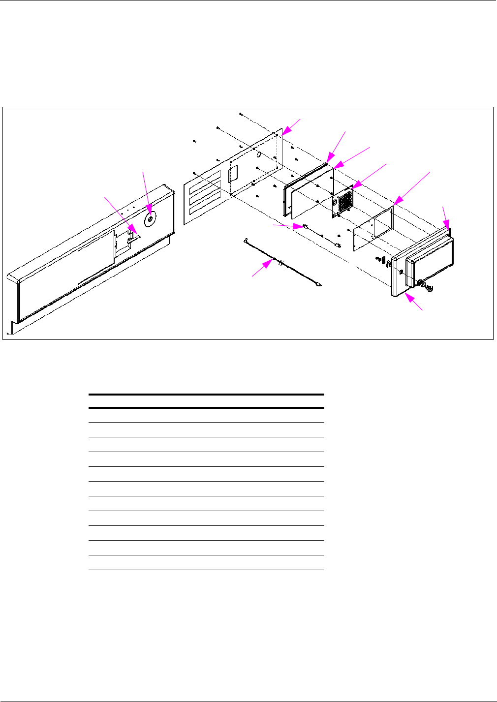
Major Hardware Components TRIND Option Doors with Antennas
Page 4-22 MDE-3664B TRIND® Start-up, Service, and Parts Manual · June 2013
MPD-3 Bezel Assemblies (T20616)
The following sections provide parts information for the MPD-3 Bezel Assemblies.
Figure 4-23: MPD-3 Bezel Assembly (T20616-G1)
MPD-3 Housing
Neoprene
Sponge Tape
TI/RFID Antenna
Assembly
Light Micro Reader PCA
Inside Cover Gasket
Inside Cover, MPD-3 Housing
Bezel Panel Assembly
Cable Access Gasket
Lock Plate
Interface hand-held
Antenna Cable
TRIND Option Door
Data and Power Cable
MPD-3 Bezel Assembly
Following table lists the MPD-3 Bezel Assembly parts:
Item Description Part Number
1Housing, MPD-3 T20417-G1
2Tape, Single Coated Neoprene Sponge Q11899-02
3TI/RFID Antenna Assembly T20524-G1
4Light Micro Reader PCA T20601-G1
5Inside Cover Gasket R20584-01
6Inside Cover, MPD-3 Housing T20216-01
7Bezel Panel Assembly T17446-G8
8Interface Hand-held Antenna Cable R20522-G2
9TRIND Option Door Data and Power Cable R20773-G2
10 Cable Access Gasket N23881-01
11 Plate, Lock N23873-G1

MDE-3664B TRIND® Start-up, Service, and Parts Manual · June 2013 Page 4-23
TRIND Option Doors with Antennas Major Hardware Components
Figure 4-24: MPD-3 Bezel Assembly (T20616-G2)
TRIND Option
Door Data and
Power Cable
Interface Hand-held
Antenna Cable
MPD-3 Housing
Cable Access
Gasket
Self Locking Hex Nut
Washer Gasket
Split Space
Bezel Panel Assembly
MPD-3 Housing Inside Cover
Inside Cover Gasket
Light Micro Reader PCA
TI/RFID Antenna Assembly
Neoprene
Sponge Tape
MPD-3 Bezel Assembly
Following table lists the MPD-3 Bezel Assembly parts:
Item Part Description Part Number
1Housing, MPD-3 T20179-01
2Tape, Single Coated Neoprene Sponge Q11899-02
3TI/RFID Antenna Assembly T20524-G1
4Light Micro Reader PCA T20601-G1
5Inside Cover Gasket R20584-01
6Inside Cover, MPD-3 Housing T20216-01
7Bezel Panel Assembly (see note 1) T17534-G05
8Interface Hand-held Antenna Cable R20522-G2
9TRIND Option Door Data and Power Cable R20773-G2
10 Cable Access Gasket N23881-01
11 Spacer, Split (see note 2) K87404-01
12 Gasket, 0.88 O.D. (see note 2) Q11659-01
13 Washer (see note 2) N16599-78
14 Nut, Self Locking Hex (see note 2) Q10218-01
Notes:
1. Bolt-on Panel for Mack Bezels.
2. Bezel Assembly requires a quantity of six (6).

Major Hardware Components TRIND Option Doors with Antennas
Page 4-24 MDE-3664B TRIND® Start-up, Service, and Parts Manual · June 2013
Figure 4-25: MPD-3 Bezel Assembly
MPD-3 Housing
Lens Retainer Bracket
TI/RFID Antenna PCB Assembly
TI/RFID Light/Micro Reader PCB
Inside Cover Gasket
MPD-3 Housing Inside Cover
Bezel Panel Assembly
Cable Access Gasket
Neoprene
sponge
Tape
Light Micro
Leader Cable
Cable Interface/Micro Reader
Lock Plate
O-ring
Mobil Lens
Diffuser
Hand-held Antenna
Interface Cable
MPD-3 Bezel Assembly
Following table lists the MPD-3 Bezel Assembly parts:
Item Part Description Part Number
1Housing, MPD-3 T20179-01
2Tape, Single Coated Neoprene Sponge Q11899-02
3O-ring, 4.25 X 4.28 Q13575-02
4Lens, Mobil Q13575-01
5 Diffuser Q13575-03
6Bracket, Lens Retainer Q13575-04
7TI/RFID Antenna PCB Assembly T20143-G1
8TI/RFID Light/Micro Reader PCB T20446-G1
9Gasket, Inside Cover R20584-01
10 Inside Cover, MPD-3 Housing T20216-01
11 Bezel Panel Assembly T17446-G8*
12 Gasket, Cable Access N23881-01
13 Plate, Lock N23873-G1
14 Cable, Hand-held Antenna Interface R20522-G1
15 Cable, Light Micro Reader R20519-G3
16 Interface/Micro Reader, Cable R20521-G3
*Slide-in panel for PMI bezels.

MDE-3664B TRIND® Start-up, Service, and Parts Manual · June 2013 Page 4-25
TRIND Option Doors with Antennas Major Hardware Components
Advantage Wide Frame Option Door Assemblies
This section provides parts data for The Advantage Series Wide Frame Option Doors
Assemblies.
Figure 4-26: Advantage Wide Frame (48 inches) Option Door Assembly
Lens Retainer Bracket
Logo Lens
O-ring
Door Gasket
Right Option Door
TI/RFID Door Antenna
Antenna Interface Cable
Light Micro Reader PCB
Antenna Shield
Wayne® Diffuser
Advantage Wide Frame Option Door Assembly
Following table lists The Advantage Series Wide Frame Option Door Assembly parts:
Item Part Description Part Number
1TI/RFID Door Antenna T20143-G1
2Light Micro Reader PCB* T20446-G1
3Antenna Shield T20210-01
4Lens Retainer Bracket Q13575-04
5Diffuser, Wayne Q13575-03
6Logo Lens Q13575-01
7O-ring Q13575-02
8Door Gasket R20424-01
9Option Door, Right T17499-06
10 Antenna Interface Cable R20522-G1
*Replaced T20182-G1 and T20295-G1.

Major Hardware Components TRIND Option Doors with Antennas
Page 4-26 MDE-3664B TRIND® Start-up, Service, and Parts Manual · June 2013
Figure 4-27: Advantage Wide Frame (48 inches) Option Door Assembly
Wide Frame Shield
Right Option Door
Door Gasket
TRIND Antenna PCB
RFID Light/Micro Reader PCA
Solid Strip Grommet
Advantage Wide Frame Option Door Assembly Parts List
Following table lists the Advantage Wide Frame Option Door Assembly parts:
Item Part Description Part Number
1Wide Frame Shield T20570-G1
2Solid Strip Grommet Q10315-06
3RFID Light/Micro Reader PCA (see note 1) M01580A00X
4TRIND Antenna PCB T20524-G1
5Door Gasket R20424-01
6Right Option Door (see note 2) T20415-0X
Notes:
1. Order entry item available as -A001 and -A002.
2. Order entry item available as -01 through -08.
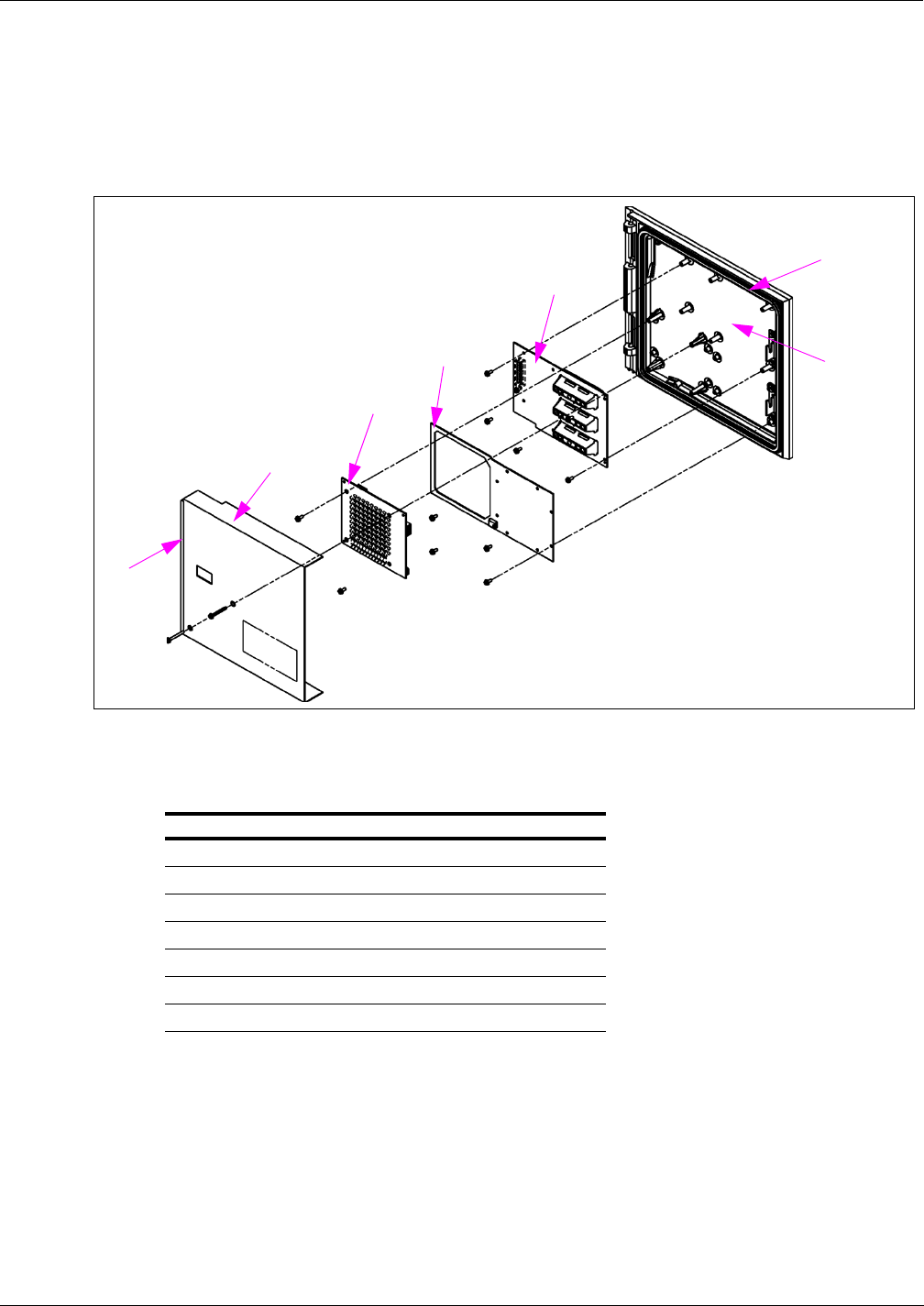
MDE-3664B TRIND® Start-up, Service, and Parts Manual · June 2013 Page 4-27
TRIND Option Doors with Antennas Major Hardware Components
Advantage Narrow Frame Option Door Assemblies
This section provides parts data for The Advantage Series Narrow Frame Option Doors.
Figure 4-28: The Advantage Series Narrow Frame (36 inches) Option Door Assembly
N/F Option
Door
Access Door Gasket
Display PCB Assembly
TRIND Antenna Assembly PCB
RFID Light/Micro Reader
N/F Door Shield
Solid Strip
Grommet
Narrow Frame Option Door Assembly
Following table lists the Narrow Frame Option Door Assembly parts:
Item Part Description Part Number
1Solid Strip Grommet Q10315-06
2N/F Door Shield T20571-G1
3RFID Light/Micro Reader* M01580A00X
4TRIND Antenna Assembly PCB T20524-G1
5Display PCB Assembly T20262-G1
6Access Door Gasket R20424-01
7N/F Option Door T20416-01
*Order entry item available as -A001 and -A002.
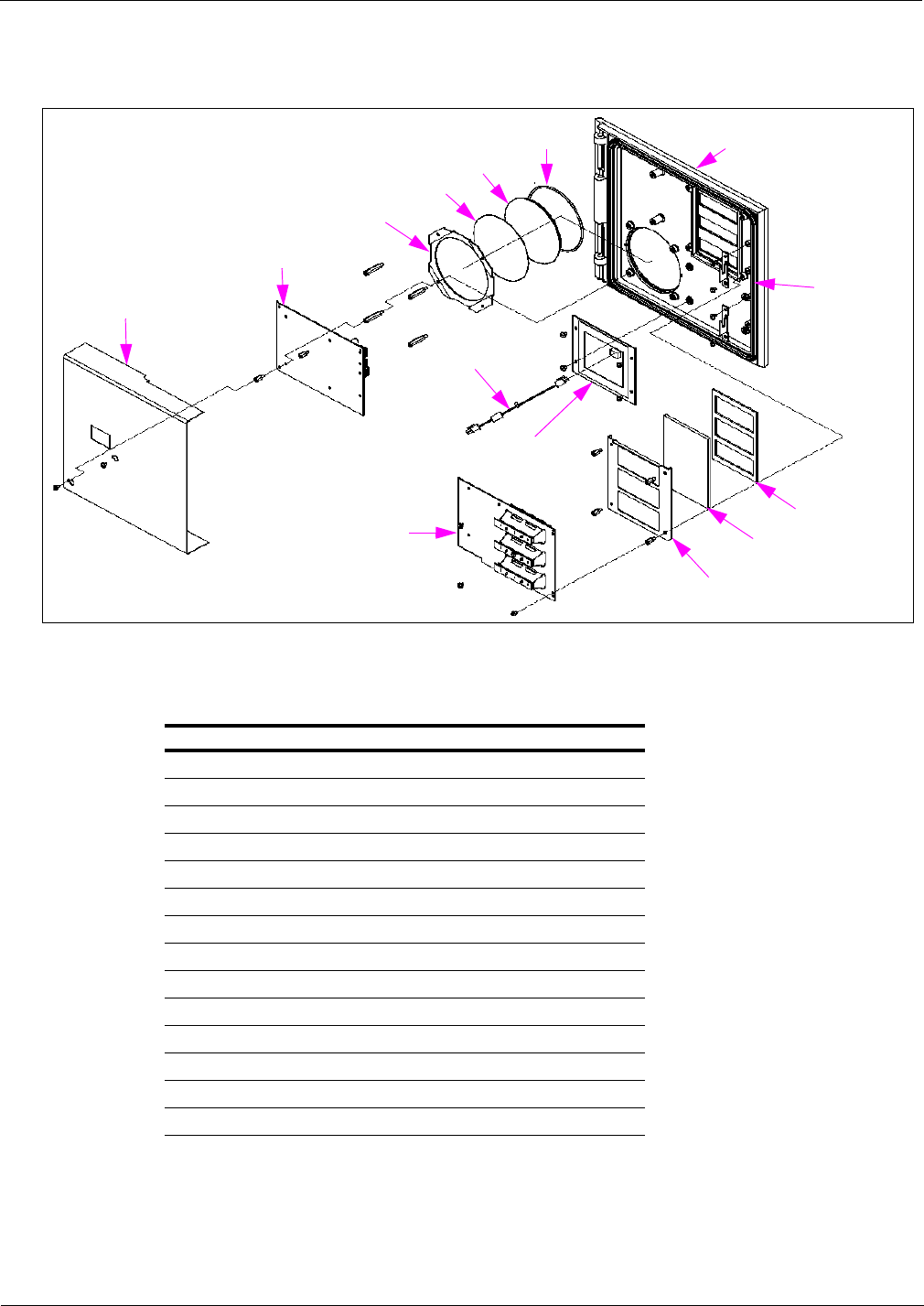
Major Hardware Components TRIND Option Doors with Antennas
Page 4-28 MDE-3664B TRIND® Start-up, Service, and Parts Manual · June 2013
Figure 4-29: The Advantage Series Narrow Frame (36 inches) Option Door Assembly
Access Door
Gasket
N/F Option Door
O-ring
Mobil lens
Diffuser
Lens Retainer Bracket
TI/RFID Light/Micro Reader PCB
Antenna Shield
Cable, Hand-held
Interface
TI/RFID
Antenna PCB
Display PCB Assembly Display Lens
Display Lens Mounting Bracket
Display Lens
Gasket
Narrow Frame Option Door Assembly
Item Part Description Part Number
1N/F Option Door (see note 1) T20125-0X
2O-ring Q13575-02
3Mobil lens Q13575-01
4Diffuser Q13575-03
5Lens Retainer Bracket Q13575-04
6TI/RFID Light/Micro Reader PCB (see note 2) T20446-G1
7Antenna Shield T20210-02
8Cable, Hand-held Interface R20522-G1
9Display PCB Assembly T20262-G1
10 TI/RFID Antenna PCB T20143-G1
11 Display Lens Mounting Bracket R20586-01
12 Display Lens R20585-01
13 Display Lens Gasket N23879-01
14 Access Door Gasket R20424-01
Notes:
1. Order entry item available as -01 and -02.
2. Replaced T20295-G1.
Following table lists the Narrow Frame Option Door Assembly parts:

MDE-3664B TRIND® Start-up, Service, and Parts Manual · June 2013 Page 4-29
TRIND Option Doors with Antennas Major Hardware Components
Encore CIM Door Option Assembly
This section provides the parts for the Encore CIM Door Option Assembly.
Figure 4-30: Encore CIM Door Option Assembly
Hex Head 6-20
Screw
Phillips Screw
TRIND Display
Window Lens
TRIND Panel Gasket
CIM Door with CRIND Assembly
TRIND Light and Indicator Assembly
Encore CIM Door Option Assembly Parts List
Following table lists the Encore CIM Door Option Assembly parts:
Item Part Description Part Number
1Screw, Hex Head 6-20 Q11677-24
2TRIND Light and Indicator Assembly M01218A00X*
3CIM Door with CRIND Assembly M01208A001
4TRIND Panel Gasket M01160B001
5TRIND Display Window Lens M01234B001
6Screw, Phillips®M00419B117
*Order entry item available as red (-A001) or orange (-A002).
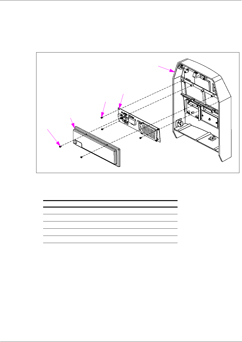
Major Hardware Components TRIND Option Doors with Antennas
Page 4-30 MDE-3664B TRIND® Start-up, Service, and Parts Manual · June 2013
Eclipse Ovendoor Option Assembly
This section provides the parts for the Eclipse Ovendoor Option Assembly.
Figure 4-31: Eclipse Ovendoor Option Assembly
TRIND Light and Indicator
Assembly
Slotted 6-20 X 0.3125
Screw
Eclipse
TRIND/Cash
Acceptor
Ovendoor
Eclipse Ovendoor
TRIND Assembly
TRIND PCB Cover
Eclipse Ovendoor Option Assembly Parts List
Following table lists the Eclipse Ovendoor Option Assembly parts:
Item Part Description Part Number
1Eclipse TRIND/Cash Acceptor Ovendoor M01509A001
2Eclipse Ovendoor TRIND Assembly M01661A001
3TRIND PCB Cover M01408B001
4Slotted 6-20 X 0.3125 Screw Q11677-23
5TRIND Light and Indicator Assembly M01218A00X*
*Order entry item available as red (-A001) or orange (-A002).

MDE-3664B TRIND® Start-up, Service, and Parts Manual · June 2013 Page 4-31
TRIND Option Doors with Antennas Major Hardware Components
Light/Micro Reader PCB (T20446-G1, T20601-GX, M01580A001, and
M01580A002)
Note: T20446 replaced Light/Micro Reader PCB T20182-G1 and T20295-G1. M01580A001
and M01580A002 replaced Light/Micro Reader PCB T20601-G1 and G2.
The PCB is mounted on the right options door on The Advantage Series units or in an
enclosure mounted on the bezel for MPD-3 units. The PCB processes data received from the
hand-held transponder and provides tag read indicator lights for the TRIND system. The PCB
requires both 5 VDC and 22.5 VDC supplied at P182 plug. The PCB also provides hand-held
transmitter information to the DCB or Enhanced Gateway Board. In addition, the PCB
receives information regarding light control from the DCB. These activities are also done
through P182 plug.
Figure 4-32: T20446-G1 Light/Micro Reader PCB
Note: Used with T20229 Card Cage in C00011-001 Kit.
Figure 4-33: T20601-G1 Light/Micro Reader PCB
Note: Used with T20606-GX Card Cage in C00011-002 Kit and above.
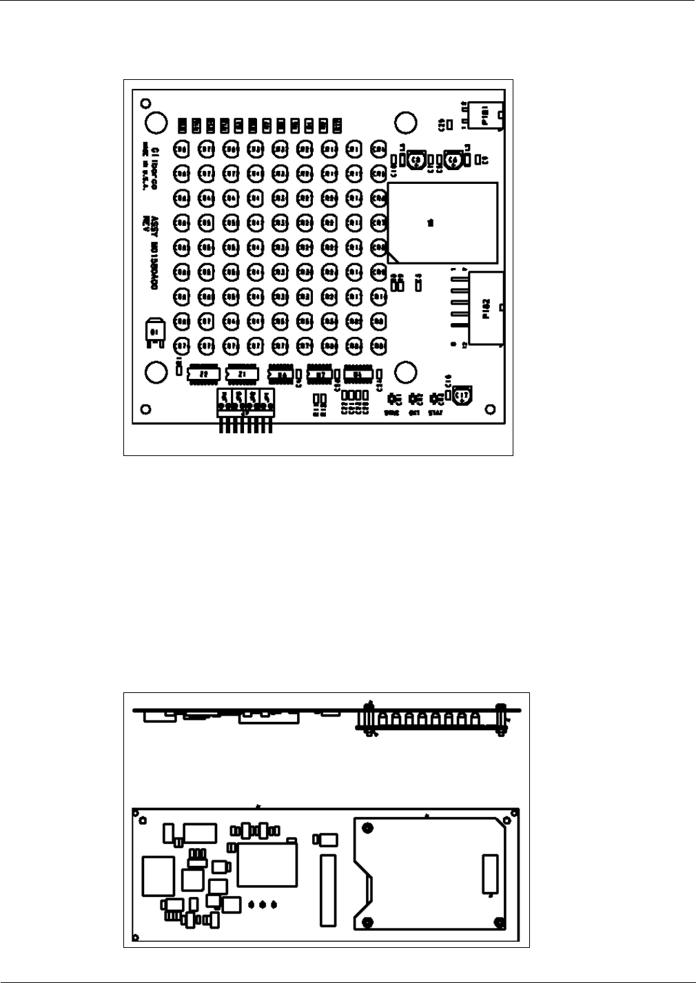
Major Hardware Components TRIND Option Doors with Antennas
Page 4-32 MDE-3664B TRIND® Start-up, Service, and Parts Manual · June 2013
Figure 4-34: M01580A00X Light/Micro Reader PCB
Note: Used with T20606-GX Card Cage in C00011-002 Kit and above.
M01218A001 and M01218A002 Light/Micro Reader PCB
Mounted on the CIM Door on Encore and Eclipse units, this PCB processes information
received from hand-held transponder (only), as well as provides indicator lights for the
TRIND system. The PCB requires both 5 VDC and 22.5 VDC supplied at P182 plug. The PCB
provides transmitter activity data to the DCB, and receives light control information from the
DCB. These activities are done through P182 plug. The antenna is integrated into this
assembly.
Figure 4-35: M01218A00X Light/Micro Reader PCB

MDE-3664B TRIND® Start-up, Service, and Parts Manual · June 2013 Page 4-33
TRIND Option Doors with Antennas Major Hardware Components
Hand-held Antenna PCB (T20143-G1)
Hand-held PCB is used on the original system and is connected to Light/Micro Reader PCB
(T20182) at P181 plug and mounted on options or bezels doors.
Figure 4-36: Hand-held Antenna PCB
TRIND Antenna PCA (T20524-G1)
The PCAs are 47uH antennas that work with the Micro Reader. They are energized by the
Micro Reader at 132 kHz to generate the exciter frequency of 134.2 kHz.
Figure 4-37: TRIND Antenna PCA

Major Hardware Components System Cables
Page 4-34 MDE-3664B TRIND® Start-up, Service, and Parts Manual · June 2013
System Cables
This section provides a description and parts information for the TRIND system cables. These
cables are used to make connections between the various TRIND and dispenser components
that comprise the TRIND system.
Note: To ensure compliance with EMC® standards, do not remove the ferrite beads from cable
assemblies provided with them.
L/HF Antenna Cable (M00878)
The Overhead Antenna Cable Assemblies (M00878A001 and M00878A002), connect the
overhead antennas to the TRIND UHF receiver and LF transmitter. The M00878A001 Cable is
used for the Encore units, the M00878A002 is used for The Advantage Series and MPD-3
units.
Note: If the unit has an Exxon Lightbox, an overhead Antenna Cable Extension
(M01380A001) used for this configuration.
Figure 4-38: L/HF Antenna Cable
M00878A001
M00878A002
Power and Data Option Door Cable (R20773)
The Power and Data Option Door Cable connects the Light/Micro Reader PCA to the TRIND
Card Cage.
Note: This cable exists in some quantities as 55 inches long. This was eventually changed to
70 inches long (Revision C and above). If you encounter the shorter version, you need
an Extender Cable (M01557A001) for each side of the dispenser.
Figure 4-39: Power and Data Option Door Cable
To DCB or Enhanced
Gateway Board
To TRIND Light Board

MDE-3664B TRIND® Start-up, Service, and Parts Manual · June 2013 Page 4-35
System Cables Major Hardware Components
R20437-G01 TRIND to CRIND Logic Cable (The Advantage Series and
MPD-3)
The R20437-G01 TRIND to CRIND Logic Cable connects the TRIND Gateway Boards
(T20128 and T20678) to CRIND Logic Boards.
Figure 4-40: R20437-G01 TRIND to CRIND Logic Cable
M00515A002 TRIND to CRIND Logic Cable for Encore 500 and Eclipse
The M00515A002 TRIND to CRIND Logic Cable for Encore 500 and Eclipse connects the
Gateway Boards to the CRIND Logic Boards.
Figure 4-41: M00515A002 TRIND to CRIND Logic Cable
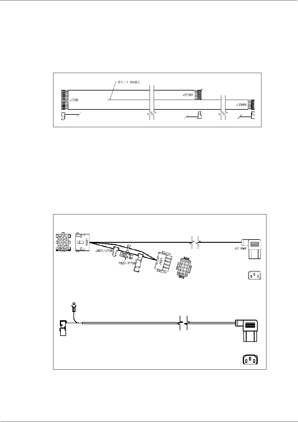
Major Hardware Components System Cables
Page 4-36 MDE-3664B TRIND® Start-up, Service, and Parts Manual · June 2013
M001804A001 TRIND to CRIND Logic Cable for Encore 300
The M001804A001 TRIND to CRIND Logic Cable for Encore 300 connects the Gateway
Boards to the CRIND Logic Boards.
Figure 4-42: M001804A001 TRIND to CRIND Logic Cable
AC Power Cables (R20580 and M00811A001)
The AC Power Cables are used to provide system power to the TRIND Card Cage assembly.
Connections for these cables are unit specific. Use appropriate connector to intercept power on
existing unit power cable.
Figure 4-43: AC Power Cables
R20580
M00811A001

MDE-3664B TRIND® Start-up, Service, and Parts Manual · June 2013 Page 4-37
System Cables Major Hardware Components
Full System Cable Connections on Legacy and Advantage Series
Dispensers
For all single-sided units, install Dummy Load Connector (R20526-01) on JB on transmitter
PCB and skip all Side B connections.
Note: If power is applied to Card Cage without the antenna cables or dummy load connected,
the transmitter board will be damaged.
On Cable Connect To On
R20509-G2 (marked for Side A) P1/2 J1 Side A Overhead Antenna (low frequency)
PA/B *JA Transmitter PCB Q13564
R20509-G2 (unmarked for Side B) P1/2 J2 Side B Overhead Antenna (low frequency)
PA/B *JB Transmitter PCB Q13564
R20519-G1 J182 P182 Light/Micro Reader PCB Assembly T20182 on Side A Options Door
P7 *J7 DCB PCB Q13563
R20519-G2 J182 P182 Light/micro Reader Pcb Assembly T20182 on Side B Options Door
P8 *J8 DCB PCB Q13563
R20521-G1 J180 P180 Light/Micro Reader PCB Assembly T20182 on Side A Options Door
J177 *P177 Power supply PCB T20138
GRD *Ground Stud Card Cage
R20521-G2 J180 P180 Light/Micro Reader PCB Assembly T20182 on Side B Options Door
J176 *P176 Power Supply PCB T20138
GRD *Ground Stud Card Cage
Q13578-01 -01 (marked for Side A) P1 J1 Side A Overhead Antenna (HF)
P1 *J2B Receive PCB
Q13578-01 (unmarked for Side B) P1 J2 Side B Overhead Antenna (HF)
P1 *J2A Receive PCB
R20437-G01 J250 *P250 TI Gateway PCB T20128-G1
J258A P258 Side A CRIND Logic PCB T17764
J258B P258 Side B CRIND Logic PCB T17764
R20580-G1 (per unit) 3 prong F 3 prong M Card Cage, Rear
Notes:
1. Asterisk (*) indicates connection point is on Card Cage assembly.
2. Route R20521-G1, R20521-G2, and R20437-G01 Cables through bottom of Card Cage to Side B for connections.
3. Check whether brand panel lighting ballast is connected to power supply. If so, disconnect ballast from power supply and terminate wires
ends according to NFPA 70, the National Electric Code and applicable local codes.

Major Hardware Components System Cables
Page 4-38 MDE-3664B TRIND® Start-up, Service, and Parts Manual · June 2013
Full System Cable Connections on MPD-3 Dispensers
For all single-sided units, install Dummy Load Connector (R20526-01) on JB on transmitter
PCB and skip all Side B connections.
Note: If power is applied to Card Cage without the antenna cables or dummy load connected,
the transmitter board will be damaged.
On Cable Connect To On
R20509-G2 (marked for Side A) P1/2 J1 Side A Overhead Antenna (low frequency)
PA/B *JA Transmitter PCB Q13564
R20509-G2 (unmarked for Side B) P1/2 J2 Side B Overhear Antenna (low frequency)
PA/B *JB Transmitter PCB Q13564
R20519-G3 (marked for Side A) J182 P182 Light/Micro Reader PCB Assembly T20182 on Side A Faceplate
Assembly
P7 *J7DCB PCB Q13563
R20519-G3 (unmarked for Side B) J182 P182 Light/Micro Reader PCB assembly T20182 on Side B Faceplate
Assembly
P8 *J8DCB PCB Q13563
R20521-G3 (marked for Side A) J180 P180 Light/Micro Reader PCB Assembly T20182 on Side A Faceplate
Assembly
J177 *P177 Power Supply PCB T20138
GRD *Ground Stud Card Cage
R20521-G3 (unmarked for Side B) J180 P180 Light/Micro Reader Pcb Assembly T20182 on Side B Faceplate Assembly
J176 *P176 Power Supply PCB T20138
GRD *Ground Stud Card Cage
Q13578-01 -01 (marked for Side A) P1 J1 Side A Overhead Antenna (high frequency)
P1 *J2B Receive PCB
Q13578-01 (unmarked for Side B) P1 J2 Side B Overhead Antenna (high frequency)
P1 *J2A Receive PCB
R20437-G01 J250 *P250 TI Gateway PCB T20128-G1
J258A P258 Side A CRIND Logic PCB T17764
J258B P258 Side BCRIND Logic PCB T17764
R20580-G1 P601
J601
3 prong F 3 prong M Card Cage, Rear
*Indicates connection point is on Card Cage assembly.

MDE-3664B TRIND® Start-up, Service, and Parts Manual · June 2013 Page 4-39
System Cables Major Hardware Components
Full System Cable Connections on The Advantage Series and MPD-3
Dispensers
For all single-sided units, install Dummy Load Connector (R20526-01) on JB on transmitter
PCB and skip all Side B connections.
Note: If power is applied to Card Cage without antenna cables or dummy load connected, the
transmitter board will be damaged.
On Cable Connect To On
M00878A002 PA JA Transmitter PCB Q13579-01
PB JB Transmitter PCB Q13579-01
P1A J1 Side A Low Frequency Overhead Antenna
P1B J1 Side B Low Frequency Overhead Antenna
P2A J2A UHF Receive PCB Q13564
P2B J2B UHF Receive PCB Q13564
P3A J2 Side A HF Overhead Antenna
P3B J2 Side B HF Overhead Antenna
R20509-G2 (marked for Side A) P1/2 J1 Side A overhead antenna (low frequency)
PA/B *JA Transmitter PCB Q13564
R20509-G2 (unmarked Side B) P1/2 J2 Side B Overhead Antenna (low frequency)
PA/B *JB Transmitter PCB Q13564
R20519-G1 J182 P182 Light/Micro Reader PCB Assembly T20182 on Side A
Options Door
P7 *J7 DCB PCB Q13563
R20519-G2 J182 P182 Light/Micro Reader PCB Assembly T20182 on Side B
Options Door
P8 *J8 DCB PCB Q13563
R20521-G1 J180 P180 Light/Micro Reader PCB Assembly T20182 on Side A
Options Door
J177 *P177 Power supply PCB T20138
GRD *Ground Stud Card Cage
R20521-G2 J180 P180 Light/Micro Reader PCB Assembly T20182 on Side B
Options Door
J176 *P176 Power Supply PCB T20138
GRD *Ground stud Card Cage
Q13578-01 -01 (marked for Side A) P1 J1 Side A Overhead Antenna (HF)
P1 *J2B Receive PCB
Q13578-01 (unmarked for Side B) P1 J2 Side B Overhead Antenna (HF)
P1 *J2A Receive PCB
R20437-G01 J250 *P250 TI Gateway PCB T20128-G1
J258A P258 Side A CRIND Logic PCB T17764
J258B P258 Side B CRIND Logic PCB T17764
R20580-G1 (per unit) 3 prong F 3 prong M Card Cage, Rear
Notes:
1. *Indicates connection point is on Card Cage assembly.
2. Route R20521-G1, R20521-G2, and R20437-G01 Cables through bottom of Card Cage to Side B for connections.
3. Check whether brand panel lighting ballast is connected to power supply. If so, disconnect ballast from power supply and
terminate wires ends according to NFPA 70, the National Electric Code and applicable local codes.

Major Hardware Components System Cables
Page 4-40 MDE-3664B TRIND® Start-up, Service, and Parts Manual · June 2013
Hand-held System Cable Connections on The Advantage Series and MPD-3
Dispensers
For all single-sided units, install Dummy Load Connector (R20526-01) on JB on transmitter
PCB and skip all Side B connections.
Note: If power is applied to Card Cage without antenna cables or dummy load connected, the
transmitter board will be damaged.
On Cable Connect To On
R20509-G2 (marked for Side A) P1/2 J1 Side A Overhead Antenna (low frequency)
PA/B *JA Transmitter PCB Q13564
R20509-G2 (unmarked for Side B) P1/2 J2 Side B Overhead Antenna (low frequency)
PA/B *JB Transmitter PCB Q13564
R20519-G1 J182 P182 Light/Micro Reader PCB Assembly T20182 on Side A Options Door
P7 *J7 DCB PCB Q13563
R20519-G2 J182 P182 Light/Micro Reader PCB Assembly T20182 on Side B Options Door
P8 *J8 DCB PCB Q13563
R20521-G1 J180 P180 Light/Micro Reader PCB Assembly T20182 on Side A Options Door
J177 *P177 Power Supply PCB T20138
GRD *Ground
stud
Card Cage
R20521-G2 J180 P180 Light/Micro Reader PCB Assembly T20182 on Side B Options Door
J176 *P176 Power Supply PCB T20138
GRD *Ground
stud
Card Cage
Q13578-01 -01 (marked for Side A) P1 J1 Side A Overhead Antenna (HF)
P1 *J2B Receive PCB
Q13578-01 (unmarked for Side B) P1 J2 Side B Overhead Antenna (HF)
P1 *J2A Receive PCB
R20437-G01 J250 *P250 TI Gateway PCB T20128-G1
J258A P258 Side A CRIND Logic PCB T17764
J258B P258 Side B CRIND Logic PCB T17764
R20580-G1 (per unit) 3 prong F 3 prong M Card Cage, Rear
Notes:
1. *Indicates connection point is on Card Cage assembly.
2. Route R20521-G1, R20521-G2, and R20437-G01 Cables through bottom of Card Cage to Side B for connections.
3. Check whether brand panel lighting ballast is connected to power supply. If so, disconnect ballast from power supply and terminate wires
ends according to NFPA 70, the National Electric Code and applicable local codes.

MDE-3664B TRIND® Start-up, Service, and Parts Manual · June 2013 Page 4-41
System Cables Major Hardware Components
Full System Cable Connections on Encore 500 Dispensers
For all single-sided units, Dummy Load Connector (R20526-01) is installed on JB on
transmitter PCB and eliminates all Side B connections.
Note: If power is applied to Card Cage without antenna cables or dummy load connected the
transmitter board will be damaged.
On Cable Connect To On
M00515A002 J3110 P3110 CRIND Control Node PCA M00089
J250 P250 Gateway PCB T20678
M00878A001 PA JA Transmitter PCB Q13579-01
PB JB Transmitter PCB Q13579-01
P1A J1 Side A Low Frequency Overhead Antenna
P1B J1 Side B Low Frequency Overhead Antenna
P2A J2A UHF Receive PCB Q13564
P2B J2B UHF Receive PCB Q13564
P3A J2 Side A High Frequency Overhead Antenna
P3B J2 Side B High Frequency Overhead Antenna
M00811A001 P1 J1 M00806A001 Power Distribution Cable
3 Prong M P3 3 Prong F, R20206 Power Input Cable
R20509-G2 (marked for Side A) P1/2 J1 Side A Overhead Antenna (LF)
PA/B *JA Transmitter PCB Q13564
R20509-G2 (unmarked for Side B) P1/2 J2 Side B Overhead Antenna (LF)
PA/B *JB Transmitter PCB Q13564
R20519-G1 J182 P182 Light/Micro Reader PCB Assembly T20182 on Side A Options Door
P7 *J7 DCB PCB Q13563
R20519-G2 J182 P182 Light/Micro Reader PCB Assembly T20182 on Side B Options Door
P8 *J8 DCB PCB Q13563
R20521-G1 J180 P180 Light/Micro Reader PCB Assembly T20182 on Side A Options Door
J177 *P177 Power supply PCB T20138
GRD *Ground stud Card Cage
R20521-G2 J180 P180 Light/Micro Reader PCB Assembly T20182 on Side B Options Door
J176 *P176 Power supply PCB T20138
GRD *Ground stud Card Cage
Q13578 01-01 (marked for Side A) P1 J1 Side A Overhead Antenna (HF)
P1 *J2B Receive PCB
Q13578-01 (unmarked for Side B) P1 J2 Side B Overhead Antenna (HF)
P1 *J2A Receive PCB
R20437-G01 J250 *P250 TI Gateway PCB T20128-G1
J258A P258 Side A CRIND Logic PCB T17764
J258B P258 Side B CRIND Logic PCB T17764
R20580-G1 (per unit) 3 prong F 3 prong M Card Cage, Rear
Notes:
1. *Indicates connection point is on Card Cage assembly.
2. Route R20521-G1, R20521-G2, and R20437-G01 Cables through bottom of Card Cage to Side B for connections.
3. Check whether brand panel lighting ballast is connected to power supply. If so, disconnect ballast from power supply and terminate wires
ends according to NFPA 70, the National Electric Code and applicable local codes.

Major Hardware Components System Cables
Page 4-42 MDE-3664B TRIND® Start-up, Service, and Parts Manual · June 2013
Hand-held System Cable Connections on Encore 500 and Eclipse
Dispensers
Following table lists the Hand-held System Cable Connections on Encore 500 and Eclipse
Dispensers:
On Cable Connect To On
M00515A002 J3110 P3110 CRIND Control Node PCA M00089
J250 P250 Gateway PCB T20678
M00811A001 P1 J1 M00806A001 Power Distribution Cable
3 Prong M P3 3 Prong F, R20206 Power Input Cable
R20509-G2 (marked for Side A) P1/2 J1 Side A Overhead Antenna (LF)
PA/B *JA Transmitter PCB Q13564
R20509-G2 (unmarked for Side B) P1/2 J2 Side B Overhead Antenna (LF)
PA/B *JB Transmitter PCB Q13564
R20519-G1 J182 P182 Light/Micro Reader PCB Assembly T20182 on Side A Options Door
P7 *J7 DCB PCB Q13563
R20519-G2 J182 P182 Light/Micro Reader PCB Assembly T20182 on Side B Options Door
P8 *J8 DCB PCB Q13563
R20521-G1 J180 P180 Light/Micro Reader PCB Assembly T20182 on Side A Options Door
J177 *P177 Power supply PCB T20138
GRD *Ground stud Card Cage
R20521-G2 J180 P180 Light/Micro Reader PCB Assembly T20182 on Side B Options Door
J176 *P176 Power supply PCB T20138
GRD *Ground stud Card Cage
Q13578-01-01 (marked for side A) P1 J1 Side A Overhead Antenna (HF)
P1 *J2B Receive PCB
Q13578-01 (unmarked for Side B) P1 J2 Side B Overhead Antenna (HF)
P1 *J2A Receive PCB
Notes:
1. *Indicates connection point is on Card Cage assembly.
2. Route R20521-G1, R20521-G2, and R20437-G01 Cables through bottom of Card Cage to Side B for connections.
3. Check whether brand panel lighting ballast is connected to power supply. If so, disconnect ballast from power supply and terminate wires
ends according to NFPA 70, the National Electric Code and applicable local codes.

MDE-3664B TRIND® Start-up, Service, and Parts Manual · June 2013 Page 4-43
System Cables Major Hardware Components
Antenna Cable Pin-to-Pin Connections (M00878A001 and M00878A002)
P1B To J1
Pin # on
Side 1
Overhead
LF Antenna
P1A To J1
Pin # on
Side 2
Overhead
LF Antenna
P3B To J2
Pin # on
Side 1
Overhead
HF Antenna
P3A To J2
Pin # on
Side 2
Overhead
HF Antenna
PB To JB for
Side 1 Pin #
on Q13579
Transmitter
Board
PB To JB for
Single-side
Units Only With
R20526-G1
Power Resistor
PA To JA for
Side 2 Pin #
on Q13579
Transmitter
Board
P2A To J2A
for Side A
Pin # on
Q13564 UHF
Receive
Board
P2B To J2B
for Side B
Pin # on
Q13564 UHF
Receive
Board
11111 N.C. 111
2 2 - - 2 N.C. 2 - -
- - - - 3 - 3 - -
Ribbon Cable Pin-to-Pin Connections (M00515A002)
J/PA To P250 Pin # On
Gateway PCB (T20128) To P3110 Pin # on CRIND
Control Node (M00089) Function
112 RX_A
213 GND_A
314 TX_A
411 +5V_A
5 - SPARE_IN_A
6 - N.C.
7 - SPARE_OUT_A
8 5 RX_B
9 6 GND_B
10 -TX_B
11 4+5_B
12 -SPARE_IN_B
13 -N.C.
14 -SPARE_OUT_B
Antenna Cable, Low Frequency Pin-to-Pin Connections (R20509-G1)
For single-sided units R20526 (see below) replaces R20509-G1 Cable used on Side B.
To JA/JB Pin # on Low
Frequency Transmitter
Board (Q13579)
To J1/J2 Pin # on Over
Head Low Frequency
Antenna
1 1
2 2
3* unused
Note: *indicates to Ground.

Major Hardware Components System Cables
Page 4-44 MDE-3664B TRIND® Start-up, Service, and Parts Manual · June 2013
Light/Micro Reader Cables Pin-to-Pin Connections (R20519-G1, R20519-G2,
and R20519-G3)
To J7/J8 Pin # on Data
Control Board (Q13563) To P182 on Light/Micro
Reader PCB (T20182) Function
1 1 TX 232
2 2 GPO 232
3 3 AX 232
4 4 Light 232
5 5 RDEN
6 6 GND
R20521-G1 and R20521-G2 Interface Micro Reader Cables Pin-to-Pin
Connections
To P176/P177 Pin # on Power
Supply Board To P180 Pin # on Light/
Micro Reader PCB (T20182) Function
1 1 +22v
2 2 +5v
3 3 GND
R20522-G1 Interface Hand-held Antenna Cable Pin-to-Pin Connections
To P190 Pin # on Hand-held
Antenna T20143 To P181 Pin # on Light/
Micro Reader PCB T20182
1 1
2 2
R20522-G2 Interface Hand-held Antenna Cable Pin-to-Pin Connections
To P190 Pin # on Hand-held
Antenna T20524 To P181 Pin # on Light/Micro
Reader PCB T20601
1 1
2 2
R20526 TI/RFID Dummy Load Transmitter Cable Pin-to-Pin Connections
Used for single-sided units in place of Side B R20509-G1 Cable to provide dummy load. If
TRIND unit is powered without load on both Side A and B of Low Frequency Transmitter
Board (Q13579) will be damaged.
R20526 Pin # To JB Pin # on Low Frequency
Transmitter Board (Q13579)
1 1
2 2
3 3

MDE-3664B TRIND® Start-up, Service, and Parts Manual · June 2013 Page 4-45
System Cables Major Hardware Components
R20437-G01 TRIND to CRIND Logic Cable Pin-to-Pin Connections
Pin # on T20128
Gateway PCB Pin # Side A P258 of
CRIND Logic Board Pin # on Side B P258 of
CRIND Logic Board Function
1 1 - RX-A
2 2 - GND-A
3 3 - TX-A
4 4 - +5V-A
5 5 - Spare-In-A
6 6 - N.C.
7 7 - Spare-Out-A
8 - 1 RX-B
9 - 2 GND-B
10 - 3 TX-B
11 - 4 +5V-B
12 - 5 Spare-In-B
13 - 6 N.C.
14 - 7 Spare-Out-B
R20773-G2 Advantage Option TRIND Data and Power Cable Pin-to-Pin
Connections
To Pin # on Side 1 and Side 2 Micro
Reader PCB Plug P182
(M01218A001/A002)
To Pin # on TRIND Card Cage
Harness Cable (T20662-G2) Plug P1
and P2 Function
1 1 TX
2 2 RX
3 3 GPO
4 4 GND
5 5 VCC
6 6 N.C.
7 7 -
8 8 ILLUM
9 9 GND
10 10 +22V
11 11 RDEN
12 12 N.C.

Major Hardware Components System Cables
Page 4-46 MDE-3664B TRIND® Start-up, Service, and Parts Manual · June 2013
R20773-G2 Encore Option TRIND Data and Power Cable Pin-to-Pin
Connections
To Pin # on Side A and Side B
T20601 Light/Micro Reader
PCB Plug P182 To Pin # on TRIND Card Cage Harness
Cable (T20662-G2 Plug P1 and P2 Function
1 1 TX
22) RX
3 3 GPO
4 4 GND
5 5 VCC
6 6 N.C.
7 7 -
8 8 ILLUM
9 9 GND
10 10 +22V
11 11 RDEN
12 12 N.C.
T20662-G2 TRIND Card Cage Cable Harness Cable Pin-to-Pin Connections
From P1
Pin # on
T20662
TRIND
Card
Harness
Cable
To J1/J2
Pin # on
Side 1
R20773
TRIND
Data and
Power
Cable
From P2
Pin # on
T20662
TRIND
Card
Harness
Cable
To J1/J2
Pin # on
Side 2
R20773
TRIND
Data and
Power
Cable
From P7
Pin # on
T20662
TRIND
Card
Harness
Cable
To J7
Pin #
For
Q13563
DCB
From P8
Pin # on
T20662
TRIND
Card
Harness
Cable
To J8 Pin
# For
Q13563
DCB
From
J176 Pin
# on
T20662
Card
Harness
Cable
To P176
Pin # on
Power
Supply
PCB
From
J177 Pin
# on
T20662
Card
Harness
Cable
To P177
Pin # on
Power
Supply
PCB
1 1 1 1 1 1 1 1 1 1 1 1
2 2 2 2 2 2 2 2 2 2 2 2
3 3 3 3 3 3 3 3 3 3 3 3
4 4 4 4 4 4 4 4 - - - -
5 5 5 5 5 5 5 5 - - - -
6 6 6 6 6 6 6 6 - - - -
7 7 7 7 - - - - - - - -
8 8 8 8 - - - - - - - -
9 9 9 9 - - - - - - - -
10 10 10 10 - - - - - - - -
11 11 11 11 - - - - - - - -
12 12 12 12 - - - - - - - -
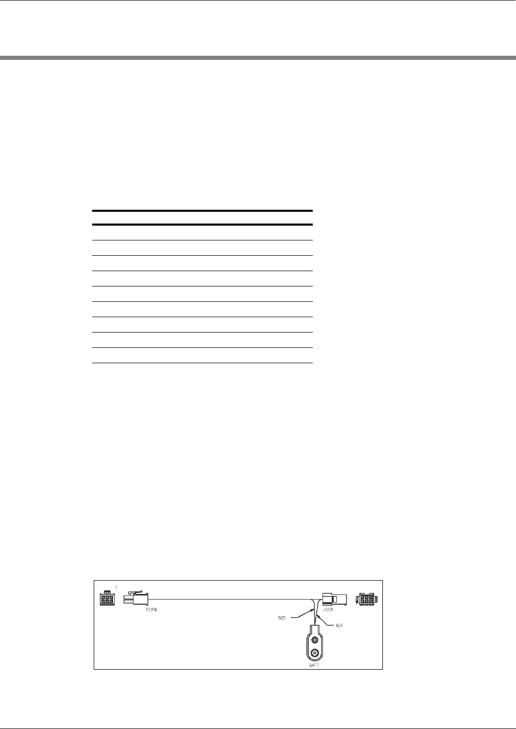
MDE-3664B TRIND® Start-up, Service, and Parts Manual · June 2013 Page 5-1
ASC TRIND Tool Kit (K94577-01) System Accessories
5 – System Accessories
ASC TRIND Tool Kit (K94577-01)
The ASC TRIND Tool Kit contains specialized tools required for installation and service of
TRIND equipped units.
Kit Contents
The Tool Kit contains the following items
Description Part Number Quantity
Cable, Standalone Jumper R20602-G1 1
Cable, Standalone Jumper R20602-G2 1
Co-axial Cable Tool Q13628-01 1
Field Strength Sensor Board Q13626-01 1
Test Tag, TI/RFID Car Mount Q13630-01 1
Test Tag, TI/RFID Hand-held Q13630-02 1
Threaded Rod, 3/8-16 X 4” N23880-01 4
Tuning Tool, Plastic Tipped Q13631-01 1
Tuning Tool, Plastic Tipped Q13631-02 1
.
Standalone Jumper Cables
Standalone Jumper Cable (R20602-G1) for LF/UHF Full System
This cable is used for MPD-3 installation or troubleshooting on any unit that requires placing
the unit the standalone mode. After powering down unit, either Side A or B Light Micro
Reader Cable (R20519-G3) is disconnected from either J8 (Side B) or J7 (Side A) on DCB in
the TRIND Card Cage, and Standalone Jumper Cable is connected in-line (between J8 and P8
or between J7 and P7). A standard alkaline 9 V battery (not supplied with kit) must be
connected to Standalone Jumper Cable.
Figure 5-1: R20602-G1 Standalone Jumper Cable

System Accessories Standalone Jumper Cables
Page 5-2 MDE-3664B TRIND® Start-up, Service, and Parts Manual · June 2013
Note: If Standalone Jumper or 9 V battery is not available, unit can be put in standalone using
the jump jack on JP3.
Connector on R20602-G1 Connects To On
J7/J8 Either J7 or J8 DCB PCB on Card Cage
P182 Either P7 or P8 Side A or B Light Micro Reader Cable (R20519-G3)
Battery connectors Battery terminals Standard 9 V alkaline battery
Figure 5-2: R20602-G1 Card Cage Connections and Wiring Diagram
J8 and J7
on TRIND Card Cage
Wiring Diagram
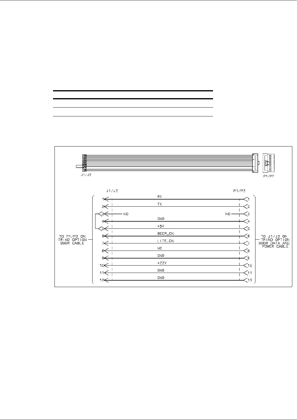
MDE-3664B TRIND® Start-up, Service, and Parts Manual · June 2013 Page 5-3
Standalone Jumper Cables System Accessories
Standalone Jumper Cable (R20602-G2) for Enhanced Gateway
This cable is used for installation or troubleshooting, and for placing a unit in the “standalone”
mode. The hand-held key tag units contain the T20606-G3 Card Cage Assembly and the
Enhanced Gateway PCB (T20678-G1). After powering down unit, the P1 end of the
M00507A001 Cable coming out of the Card Cage on Side A is disconnected. The P1/P2 end
of the Standalone Jumper Cable is connected to the P1 end of the M00507A001 Cable, and the
J1/J2 end of the Standalone Jumper Cable is connected to the J1/J2 end of the R20773-02
Cable that is connected to the Light Board Assembly (M01218A001). TRIND is in the
“standalone” mode when power is restored to the unit.
Connector on R20602-G2 Connects To On
P1/P2 P1 M00507A001 Cable (Side A)
J1/J2 J1/J2 R20773-G2 Cable
Figure 5-3: R20602-G2 Standalone Jumper Cable and Wiring Diagram
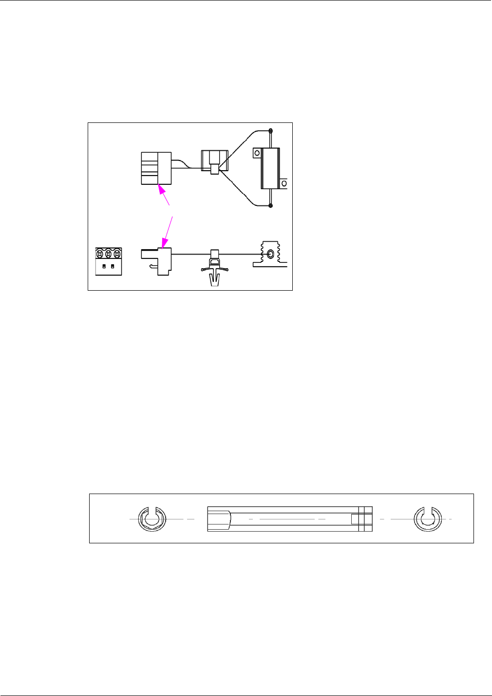
System Accessories Dummy Load Transmitter (R20526)
Page 5-4 MDE-3664B TRIND® Start-up, Service, and Parts Manual · June 2013
Dummy Load Transmitter (R20526)
Dummy Load Transmitter must be installed on JB of Transmitter PCB.
Figure 5-4: Dummy Load Transmitter
To JB
Co-axial Cable Tool (Q13628-01)
Co-axial Cable Tool is a hex-socket tool with a slit down its length. Co-axial cables are
(M00878A001, M00878A002, and Q13578-01) are used for transmission from TRIND
overhead antennas and come with hex connectors at either end. The Co-axial Cable Tool
allows the installer to tighten cable connections in tight areas of the TRIND Card Cage and
overhead connection box.
Note: Co-axial cable fits in to the slotted side of the Co-axial Cable Tool, allowing the socket
to surround the hex-head of the cable connector. This allows connections to be made
and tightened straight on, rather than from the side.
Figure 5-5: Co-axial Cable Tool

MDE-3664B TRIND® Start-up, Service, and Parts Manual · June 2013 Page 5-5
Field Strength Sensor Board (Q13626-01) System Accessories
Field Strength Sensor Board (Q13626-01)
TRIND installation manuals and this document details the installation test for positioning of
the Field Strength Sensor Board during antenna field tuning.
Figure 5-6: Field Strength Sensor Board
Red and
Black Leads
Set the multimeter to DC voltage. Connect the red and black leads of the standard multimeter
to the field strength sensor board leads. As the antennas are tuned by incremental adjustments
to the antenna’s variable inductor (similar to a tuning pot), voltage reading increases or
decreases. The field strength sensor board allows you to find the voltage peak, which is the
tuning target.
Q13630-01 and Q13630-02 Test Tags
Hand-held Test Tag (Q13630-01) simulates a hand-held transponder and has the appearance of
a key holder. Car-mount Test Tag (Q13630-02) simulates a customer’s car mounted
transponder. These tags are used to test operation of the TRIND system at installation.
Figure 5-7: Test Tags
Car-mount Test Tag
(Q13630-02)
Hand-held Test Tag
(Q13630-01)

System Accessories Tuning Tool (Q13631-01 and Q13631-02)
Page 5-6 MDE-3664B TRIND® Start-up, Service, and Parts Manual · June 2013
Hand-held Test Tag
During testing, the Hand-held tag is placed against the TRIND target on either the right
options door on The Advantage Series, or on the faceplate target located on the right side of
MPD-3 bezel doors.
Note: Use of the test tags will cause a properly installed and operating TRIND system’s target
logo to light, indicating successful reading. An actual sale is not possible with these
tags.
Car-mount Test Tag
Car-mount test tag is positioned properly when it is 6 feet from the overhead antennas and in a
position that approximates that of a car’s dashboard at the fuel island.
Note: The car tag has a replacable battery that has a life of two to three years.
Tuning Tool (Q13631-01 and Q13631-02
Only the Plastic Tuning Tool [Q13631-01 (or similar plastic 0.10-inch hex tool)], which is a
part of ASC Tool Kit (K94577-01) must be used for tuning overhead antennas. Using a
metal screwdriver or Allen wrench has two negative effects. First, proper tuning is
impossible as the metal of the tool used changes the properties of the variable inductor
used for tuning. Secondly, the ferrite slug used in the variable inductor is extremely brittle
and is broken or stripped easily by metal tools, preventing the proper tuning of the
antenna. If the antenna is not properly tuned, the read range can be significantly reduced.
CAUTION
)
In conjunction with Field Strength Sensor Board (Q13626-01), tuning tools are used to make
variable inductor adjustments to tune the overhead antennas. The tools are plastic and
non-reactive to the variable inductor or board on the overhead antennas, and should only be
used to adjust variable inductor.
Figure 5-8: Tuning Tools
Q13631-01
Q13631-02
Variable
Inductor
Q13582-02
T20579-GX
The Q13631-01 plastic flat-blade is used the same as a screwdriver. It is used with Q13582-02
and fits the slotted head of the variable inductor located on the overhead antenna PCB.
The Q13631-02 plastic blade is used the same as an Allen wrench. The wrench is used with
Antenna Tuning Board (T20579-GX) and fits the Allen head of the variable inductor located
on the Overhead Antenna PCB (T20579-GX, located in T20632-GX Assemblies).

MDE-3664B TRIND® Start-up, Service, and Parts Manual · June 2013 Page 6-1
Positioning Overhead Antennas Procedures for Factory Installed TRIND
6 – Procedures for Factory Installed TRIND
Positioning Overhead Antennas
TRIND overhead antennas are shipped mounted to the unit in the down position. Figure 6-1
shows the TRIND antenna hardware and final antenna positioning on the unit.
Figure 6-1: Positioning TRIND Antenna
Perform the following procedures to position each overhead antenna:
Note: If installing the Mobil Display Cabinet (Blue Hat), leave the antennas in the down
position until the display cabinet is installed. For display cabinet installation
instructions, refer to “Dispenser Setup” on page 7-1.
See Figure 6-1 and perform the following steps to position the overhead antenna into its final
position. Perform these steps for each side of the unit:
1Loosen the bolts on the each side of the unit that secure the antenna boxes to the antenna
brackets using a 3/8-inch nut driver.
2Slide the antenna forward and away from the fueling unit in the bracket slots.
3Rotate the antenna to the upright position parallel to the ground.
Molded Tab
Bolt Slot
Wires
Bolt

Procedures for Factory Installed TRIND Positioning Overhead Antennas
Page 6-2 MDE-3664B TRIND® Start-up, Service, and Parts Manual · June 2013
4Slide the antenna back towards the unit until the bolts stops in the slots and the molded part of
the antenna bracket is secure inside the bracket fork.
Note: Before tightening the bolts, ensure that the cables coming from the antenna are securely
positioned inside the stamped groove part of the bracket and are not trapped under the
bracket.
5Tighten the bolts that secure the antenna into position using the 3/8-inch nut driver or
equivalent.
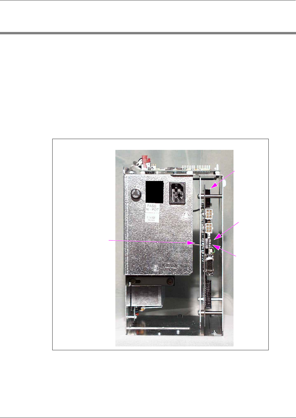
MDE-3664B TRIND® Start-up, Service, and Parts Manual · June 2013 Page 7-1
Addressing Dither Sync Address for LF/UHF Full System Dispenser Setup
7 – Dispenser Setup
Addressing Dither Sync Address for LF/UHF Full System
Each dispenser on the G-SITE® system controller must be addressed differently; no two
dispensers may have the same address. Addresses are at discretion of the installer.
Note: Before installing the Card Cage inside the dispenser, locate the dip switches on the DCB
inside the Card Cage assembly (see Figure 7-1).
Figure 7-1: DCB and Dip Switch Location
Switch Numbers = Value
1 = Standalone Mode
2 = 1
3 = 2
4 = 4
5 = 8
1
2
3
4
5
Dip Switch Down
Dip Switch Up
DCB
1From Side A of unit, locate the dip switches on the DCB inside the Card Cage.
2Using switches 2, 3, 4, and 5, address each dispenser so that no two dispensers at one side are
identical.

Dispenser Setup Setting Baud Rate
Page 7-2 MDE-3664B TRIND® Start-up, Service, and Parts Manual · June 2013
Setting Baud Rate
For Major Oil Company (MOC) TRIND installations, there is no requirement to set or change
baud rate.
Addressing Gateway/Enhanced Gateway Board
Addresses for the TRIND device must match the addresses on CRIND Logic Board.
1Access the unit’s CRIND Logic Board. Refer to MDE-2562 CRIND Service Manual.
2Locate jump jacks on A and B side CRIND Logic Boards [T17764-XX (see Figure 7-3 on
page 7-3)].
3Note position of jump jacks and set jump jacks on Gateway/Enhanced Gateway Board
(see Figure 7-2) to match address on CRIND Logic Boards (see Figure 7-3 on page 7-3) for
both Sides A and B.
Note: The Gateway Boards are assessable at the upper left hand corner at the front of the
Card Cage.
Figure 7-2: Gateway Boards Jump Jack Locations
Jump Jack Locations on Enhanced Gateway Board (T20678)
Jump Jack Locations on Gateway Board (T20128)

MDE-3664B TRIND® Start-up, Service, and Parts Manual · June 2013 Page 7-3
Addressing Gateway/Enhanced Gateway Board Dispenser Setup
Figure 7-3: CRIND Logic Board (T17764-XX)
U7
Chip
Orientation
Notch
T17764-XX
CRIND
Logic Board
(-G3 shown)
JP1-16

Dispenser Setup Addressing Gateway/Enhanced Gateway Board
Page 7-4 MDE-3664B TRIND® Start-up, Service, and Parts Manual · June 2013
CRIND Address Table
Following table provides a cross-reference between addresses on the T17764 CRIND Logic
Board and the Gateway Boards.
MOC and Generic CRIND Addresses
Address On CRIND Logic Board T17764-XX JP8 JP7 JP6 JP5 JP4
= Address on Gateway Board ‘A’ Side JP6 JP7 JP8 JP9 JP10
= Address on Gateway Board ‘B’ Side JP14 JP15 JP16 JP17 JP18
1IN OUT OUT OUT OUT
2OUT IN OUT OUT OUT
3IN IN OUT OUT OUT
4OUT OUT IN OUT OUT
5IN OUT IN OUT OUT
6OUT IN IN OUT OUT
7IN IN IN OUT OUT
8OUT OUT OUT IN OUT
9IN OUT OUT IN OUT
10 OUT IN OUT IN OUT
11 IN IN OUT IN OUT
12 OUT OUT IN IN OUT
13 IN OUT IN IN OUT
14 OUT IN IN IN OUT
15 IN IN IN IN OUT
16 OUT OUT OUT OUT IN
17 IN OUT OUT OUT IN
18 OUT IN OUT OUT IN
19 IN IN OUT OUT IN
20 OUT OUT IN OUT IN
21 IN OUT IN OUT IN
22 OUT IN IN OUT IN
23 IN IN IN OUT IN
24 OUT OUT OUT IN IN
25 IN OUT OUT IN IN
26 OUT IN OUT IN IN
27 IN IN OUT IN IN
28 OUT OUT IN IN IN
29 IN OUT IN IN IN
30 OUT IN IN IN IN
31 IN IN IN IN IN
32 OUT OUT OUT OUT OUT
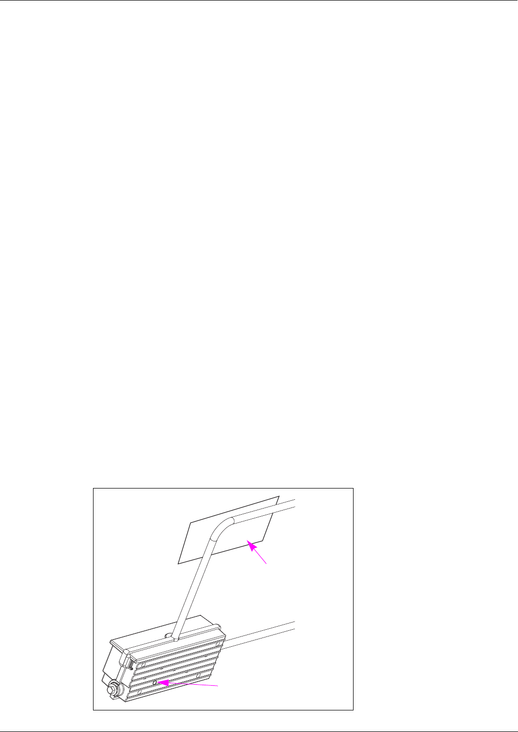
MDE-3664B TRIND® Start-up, Service, and Parts Manual · June 2013 Page 7-5
Preparation for Tuning Antennas Dispenser Setup
Preparation for Tuning Antennas
Antenna tuning requires use of Field Strength Sensor Board supplied with the ASC TRIND
Tool Kit. For information on using Field Strength Sensor Board, refer to “Field Strength
Sensor Board (Q13626-01)” on page 5-5.
1For units without G-SITE, put unit in ‘standalone’ mode. Refer to
“Standalone Jumper Cable (R20602-G1) for LF/UHF Full System” on page 5-1 and
“Standalone Jumper Cable (R20602-G2) for Enhanced Gateway” on page 5-3.
2Restore power to unit(s).
3After restoring power to the unit, verify that the unit is in “standalone” mode by observing that
the LEDs on the light board are flashing.
Tuning Antennas
Following sections provide instructions on tuning the Single-loop and Mobil antennas.
Tuning Single-loop Antennas
Perform the following steps in to tune a Single-loop Antenna.
1Locate the access port for the tuning pot in the overhead antenna connection box on Side A.
Note: Use Tuning Tool (Q13631-XX) from the ASC TRIND Tool Kit to make pot adjustments.
For instructions, refer to MDE-3640 ASC TRIND Tool Kit. Hex end of tuning tool
matches hex shape of tuning pot.
2Lay field strength sensor on the antenna as shown in Figure 7-4. Exact location is not critical.
Figure 7-4: Field Strength Sensor Positioning
Tuning Pot Access Port Location In
Overhead Antenna Connection Box
Field Strength Sensor
Underside of Antenna View

Dispenser Setup Tuning Antennas
Page 7-6 MDE-3664B TRIND® Start-up, Service, and Parts Manual · June 2013
3On the Card Cage, move the three position “tune” toggle switch (see Figure 7-5) from center
position to “A”.
Figure 7-5: Tuning Toggle Switch Locations
B
A
A
B
Tune Toggle Switch Location
4Connect the leads to field strength sensor. Position the multimeter selector switch to DC
voltage.
5By fine adjustments to tuning pot, set to highest DC voltage reading.
6Voltage will peak at a point, and then decrease with turns in either direction. Set at peak.
7Repeat steps 1 on page 7-5 through 5 for position “B” and then return tune toggle switch to
center position.
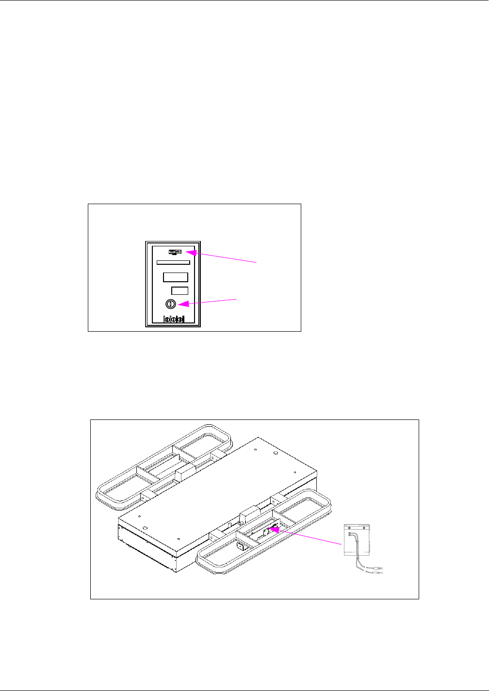
MDE-3664B TRIND® Start-up, Service, and Parts Manual · June 2013 Page 7-7
Tuning Antennas Dispenser Setup
Mobil Antennas
To tune a Mobil Antenna, proceed as follows:
1Locate variable inductor on PCB in the over-head antenna connection box. The variable
inductor, similar to a tuning pot, has a slot for the tuning tool. For more information on Mobil
Antennas, refer to “Mobil Overhead Antenna Assembly (T20231)” on page 4-14.
2The variable inductor on the Side A overhead antenna connection box should be turned out
five to six turns as a starting point.
Note: Use tuning tool from the ASC TRIND Tool Kit to make adjustments.
Figure 7-6: Variable Inductor Location
Variable inductor location in overhead
antenna connection box
Variable Inductor,
use Tuning Tool
to adjust.
J1
3Lay field strength sensor flat at a position (see Figure 7-7) on the Side A plastic antenna
housing, to the right of connection box.
Figure 7-7: Field Strength Sensor Location on Side A
Position Field
Strength Sensor
Board (Q13626-01)
Note: For consistent readings, always place sensor board in the same spot during testing.

Dispenser Setup Tuning Antennas
Page 7-8 MDE-3664B TRIND® Start-up, Service, and Parts Manual · June 2013
4On Card Cage, move the three position “tune” toggle switch from the center position to “A”.
Figure 7-8: Tune Toggle Switch Location
“Tune” toggle switch location
5Connect the leads on the multimeter to field strength sensor. Set the meter to the DC voltage
range.
6By fine adjustments to variable inductor, set to the highest DC voltage reading.
Note: Voltage will peak at a point between 12 VDC and 20 VDC, and then decrease with turns
in either direction. Set at peak.
7Repeat steps 1 on page 7-7 through 6 for Side B.
8 When finished, return the tune toggle switch to the center position.

MDE-3664B TRIND® Start-up, Service, and Parts Manual · June 2013 Page 8-1
Status Indicators Testing and Troubleshooting
8 – Testing and Troubleshooting
Following sections provide testing and troubleshooting information for the TRIND system.
The status indicator section describes the characteristics of key TRIND indicators when the
TRIND system is operating properly. The troubleshooting flow chart section provides a
graphical guide to assist in troubleshooting the TRIND system.
Note: The majority of failures that occur are attributed to insufficient initial setup detail.
Proper Gateway Board addressing and accurate cable connections are crucial to the
effective operation of the TRIND system.
Status Indicators
Following sections describe the display characteristics of key indicators when the TRIND
system is functioning properly.
Gateway Board (T20128)
Figure 8-1 shows Status indicators for the Gateway Board.
Figure 8-1: Gateway Board
CR9 CR8
CR6
CR5
CR4
CR10 CR7

Testing and Troubleshooting Status Indicators
Page 8-2 MDE-3664B TRIND® Start-up, Service, and Parts Manual · June 2013
The Gateway Board will have the following indicator characteristics when operating properly:
• +5 VDC LED on solid (CR8).
• Blinking Central Processing Unit (CPU) LED (CR6). A dimly lit LED can also indicate
proper operation because the blink rate becomes so fast that the LED appears dimmer than
the +5 VDC LED (CR8).
• Rapidly Blinking CRIND A and B LEDs. Side A is CR4 (TX), CR5 (RX), Side B is CR9
(TX). These LEDs indicate good communication with the CRIND. They mimic the LEDs
on the series of T17764 CRIND Boards. The Encore 500 Series CRIND node has two
TRIND LEDs, D12 and D13, present in board under the TRIND connector.
Enhanced Gateway Board (T20678)
Figure 8-2 shows Status indicators for the Enhanced Gateway Board.
Figure 8-2: Enhanced Gateway Board
CR9
CR8
CR6
CR5
CR4
CR10 CR7

MDE-3664B TRIND® Start-up, Service, and Parts Manual · June 2013 Page 8-3
Status Indicators Testing and Troubleshooting
Enhanced Gateway Board will have the following indicator characteristics when operating
properly:
• +5 VDC LED on solid (CR8).
• Blinking CPU LED (CR6). A dimly lit LED can also indicate proper operation because
the blink rate becomes so fast that the LED appears dimmer than the +5 VDC LED (CR8).
• Rapidly Blinking CRIND A and B LEDs. Side A is CR4 (TX), CR5 (RX), Side B is CR9
(TX). These LEDs indicate good communication with the CRIND. They mimic the LEDs
on the T17764 series of CRIND Boards. The Encore 500 Series CRIND node has two
TRIND LEDs, D12 and D13, present in board under the TRIND connector.
Data Control Board (Q13563)
Status indicators for the Q13563-01 DCB are shown in Figure 8-3 and the status indicators for
the Q13563-04 DCB are shown in Figure 8-4 on page 8-4.
Figure 8-3: Q13563-01 DCB Indicators
Heart Beat (CPU)
RS-485 (TX)
Read Ant 1
Read Ant 3
Bezel I/O Error
RS-485 (RX)
12 VDC
Vcc (+5 VDC)
J8 Bezel B
J7 Bezel A

Testing and Troubleshooting Status Indicators
Page 8-4 MDE-3664B TRIND® Start-up, Service, and Parts Manual · June 2013
Figure 8-4: Q13563-04 DCB Indicators
Heart Beat (CPU)
RS-485 (TX)
Read Ant 1 (Overhead)
Read Ant 3 (Overhead)
Bezel I/O Error
RS-485 (RX)
+12 VDC
Vcc (+5 VDC)
J8 Bezel B
J7 Bezel A
The Q13563 DCB will have the following indicator characteristics when operating properly:
• VCC and +12 VDC LEDs on solid (D14 and D13, respectively).
• Heartbeat LED (CPU) blinking (D9).
• RS-485 LED’s strobbing rapidly (D2 and D3).
Note: One may watch the communications begin between the Gateway Board and the DCB
with these LEDs. The first several sequences are the waking up of the DCB and then
commands sent down. This LED activity looks spurious. After a few rounds of that
behavior, the RS-485 LEDs will begin firing at a regular pace, indicating that a link has
been established. The RS-485 LEDs fire at a regular pace only when the Gateway
Board is looking for tags. When the CRIND does not want the Gateway to look for tags
(or has never initiated communication with the Gateway), the RS-485 LEDs fire once
every 10 seconds after any initial wakeup.
• When a car tag has been presented, the READ ANT 1 (D8) or READ ANT 3 (D7) LED
will light, depending upon the side.
• If the Bezel Input Output (I/O) error LED (D6) is on, then one of the Light/Micro Reader
Boards is not connected or has lost communication.
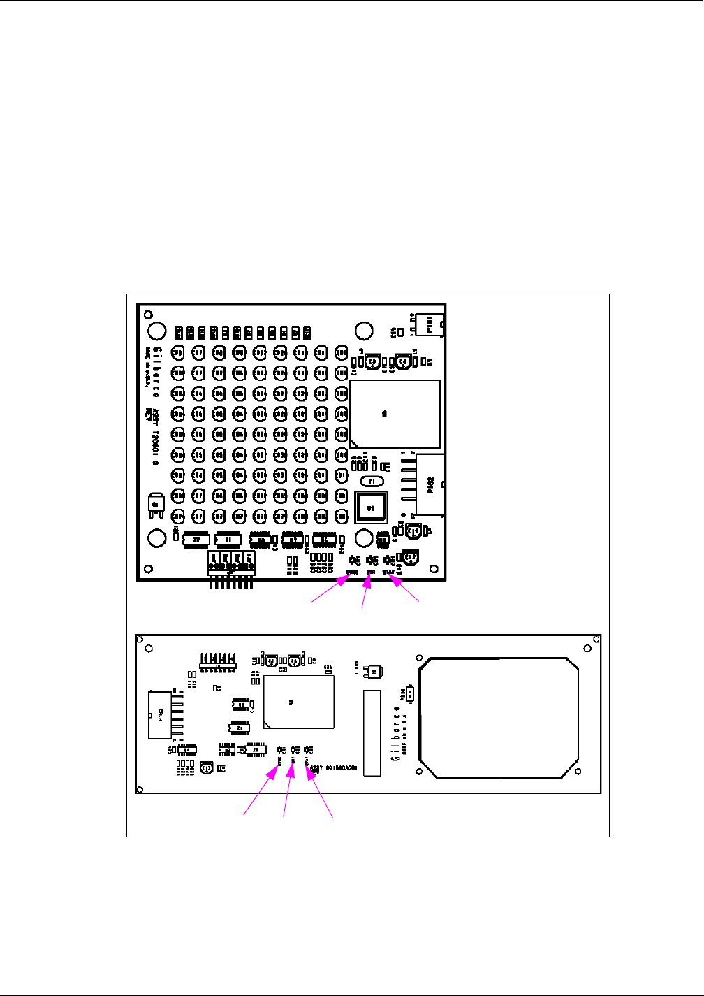
MDE-3664B TRIND® Start-up, Service, and Parts Manual · June 2013 Page 8-5
Status Indicators Testing and Troubleshooting
T20601/M01560 Light/Micro Reader Boards
The Light/Micro Reader Boards (see Figure 8-5) will exhibit the following characteristic when
operating properly:
Note: The M01560 is a subassembly of Light and Inductor PCB Assembly (M01218).
• SYNC LED blinking (CR1).
• OKT LED on solid (CR2) until a tag is presented, then it will flicker while a key tag is in
the field.
• STAT LED (CR3) blinking in unison with the SYNC LED.
• If these LEDs are solid, then the TRIND has not been told to look for tags, and
consequently will never light the LEDs on the Light/Micro Reader Board.
Figure 8-5: RFID Light/Micro Reader Boards
SYNC OKT STAT
SYNC OKT STAT
STAT
T20601
M01560

Testing and Troubleshooting Isolating TRIND from CRIND
Page 8-6 MDE-3664B TRIND® Start-up, Service, and Parts Manual · June 2013
Isolating TRIND from CRIND
To isolate the TRIND system from CRIND, proceed as follows:
1Shut off all power to unit.
2Disconnect either Side A or B Light Micro Reader Cable (R20519-G3) from either J8
(Side B) or J7 (Side A) on the DCB in the TRIND Card Cage, and insert the standalone jumper
in-line (between J8 and P8 or between J7 and P7). For jumper details, refer to “Standalone
Jumper Cable (R20602-G1) for LF/UHF Full System” on page 5-1.
Note: If Standalone Jumper Cable (R20602-G1) or 9 V alkaline battery is not available, unit
can be put in standalone mode by installing jump jack on JP3 on Light/Micro Reader
Board (for information on Isolating TRIND from CRIND, refer to “Light/Micro Reader
PCB (T20446-G1, T20601-GX, M01580A001, and M01580A002)” on page 4-31).
Perform for Side A only for the Card Cage Assembly.
3Remove J4 from DCB.
4Restore power to unit, and test TRIND operation (for information on test TRIND operation,
refer to “Dummy Load Transmitter (R20526)” on page 5-4. If TRIND functions properly the
problem is with CRIND or CRIND related equipment, refer to MDE-2562 CRIND Service
Manual.
Tag Testing
Perform the following procedures to begin TRIND tag testing. To test the full controller drive
capability, do not place TRIND in the standalone mode. Allow the dispenser network to detect
the other subsystems (pump, CRIND, TRIND, etc.). The standalone procedure will verify that
TRIND hardware is good (or not). The standalone procedure isolates TRIND from CRIND.
Car Mounted Test Tags
1Place the unit into the standalone mode. For the appropriate standalone cable connection, refer
to “Standalone Jumper Cable (R20602-G1) for LF/UHF Full System” on page 5-1.
2From Side A of the unit, hold the Car Mount Test Tag, from the ASC TRIND Tool Kit in front
of the unit at a distance of approximately 6 inches from the face of unit. Observe that the door
or faceplate TRIND indicator lights.
3Repeat steps 1 and 2 for Side B.

MDE-3664B TRIND® Start-up, Service, and Parts Manual · June 2013 Page 8-7
Tag Testing Testing and Troubleshooting
Hand-held Test Tags
To test the Hand-held Tags, proceed as follows:
1Place the unit into the standalone mode. For the appropriate standalone cable connection, refer
to “Standalone Jumper Cable (R20602-G2) for Enhanced Gateway” on page 5-3.
2From Side A of the unit, point the Hand-held Test Tag, from the ASC TRIND Tool Kit at the
TRIND target graphic (see Figure 8-6). The TRIND indicator lights when the tag is
approximately 3 inches or less away from the target graphic. Repeat for Side B.
Note: If the indicator fails to light, check whether the light on the other side is on; if so, it
indicates a crossing of Side A and B cables. Check the connections.
Figure 8-6: Positioning TRIND Hand-held Test Tag
Target Graphic
POINT MUST BE WITHIN 3 TO 6 INCHES OF TARGET GRAPHIC
IMPORTANT!
3Repeat steps 1 and 2 for Side B.

Testing and Troubleshooting Tag Testing
Page 8-8 MDE-3664B TRIND® Start-up, Service, and Parts Manual · June 2013
Alternative Testing Using Laptop
To implement the TRIND testing using the Laptop Tool, proceed as follows:
1Connect laptop to RS-232 port on DCB.
Note: The directory paths shown in steps 2 through 4, are representative of a directory
structure that may be found on a laptop or personal computer. Some directory paths
may differ depending upon the computers software setup and hardware configuration.
2Go to:
“C:\windows program(hyperterminal)\Accessories\Terminal\Settings\Communications”
3Set for:
• 9600 baud
•8 bit
• No parity
• Comm 1
4Then go to:
• Help screen\Antenna scan
• Next, at “Antenna scan”, select 1, 2, 3, and 4.
Note: This tests both antennas.
5From Side A of unit, position the Hand-held Test Tag, from the ASC TRIND Tool Kit in front
of the TRIND target graphic. Observe that the door or faceplate TRIND indicator glows.
6From Side A of unit, hold the Car Mount Test Tag from the ASC TRIND Tool Kit in front of
unit, at a distance of approximately 6 feet from overhead antenna. Observe that the door or
faceplate TRIND indicator glows.
7Repeat steps 5 and 6 for Side B.

MDE-3664B TRIND® Start-up, Service, and Parts Manual · June 2013 Page 8-9
Troubleshooting T20229-G1 PCB on Card Cage Assembly Testing and Troubleshooting
Troubleshooting T20229-G1 PCB on Card Cage Assembly
Following tables provide indications and steps to verify board operation and troubleshoot
problems.
Light/Micro Reader Board (T20295-G1)
Light/Micro-reader PCA LEDs provide the best starting point for TRIND troubleshooting
(see following table), whether TRIND is in standalone mode or connected to CRIND and
G-SITE.
The Light/Micro Reader PCA performs two functions:
• Provides the customer with an indication of authorization to begin fueling.
• Communicates hand-held tag information to DCB board.
Connection Function
P180 Receives +5 V, +22 V and GRD from TI/RFID Power Supply.
P181 Hand-held tag information is passed to Micro Reader mounted on Light/Micro Reader. Micro
Reader processed information is passed to DCB for further processing through CRIND to MOC
authorization network.
P182 When authorization is given DCB signals Light/Micro Reader Board to light LEDs through this
connection.
LED Function Indication
CR1 SYNC CR1 and CR3 indicate communications with DCB:
• Pulsing in sync operation is normal.
• Solid on, power is present but communication is not. Check whether both Side A and B
Boards give same indication. If both sides are on solid on, check Gateway and DCB
LEDs as detailed in previous sections.
• If LEDs are out, 5 V power is lost. Check connections to TI/RFID Power Supply and
voltages.
CR3 STAT
CR2 OKT Normal operation will be solid until hand-held tag is presented, at which point it will begin to
faintly flicker. This is observable in daylight, but best observed in low-light situations.

Testing and Troubleshooting Troubleshooting T20229-G1 PCB on Card Cage Assembly
Page 8-10 MDE-3664B TRIND® Start-up, Service, and Parts Manual · June 2013
Gateway PCB (T20128-G1)
Normal Operation Abnormal Operation/Failure Cause/Action Required
PWR LED (CR8) constant on;
indicates 5 V supplied
No LED activity. Check TI/RFID Power Supply
PCB for 5 V output.
CPU LED (CR6) continuous rapid
pulse. Blinking CPU LED (CR6).
A dimly lit LED can also indicate
proper operation because the
blink rate has become so fast that
the LED appears dimmer than the
+5 VDC LED (CR8).
No LED activity (indicates
software not running).
Do the following:
• CRIND reset of Gateway may
be stalled. Power TRIND down
and up and verify whether
problem is corrected.
• If not, replace Gateway PCB.
TX (CR4, CR9) and RX (CR5,
CR10) at power up display
asynchronous activity (date
transfer between Gateway and
CRIND), followed by synchronous
activity. TX LEDs indicate data to
CRIND; RX LEDs data from
CRIND.
Either or both RX LEDs on
steady.
If there is serial connection
between CRIND and Gateway is
suspect, do the following:
• P250 on Gateway PCB.
• P258 on CRIND Logic Board.
• R20437-G01 Cable
Either or both RX LEDS blinking
and TX LEDs off indicates
Gateway not responding to
CRIND poll.
Do the following:
• Check address jump jack
settings on CRIND and
Gateway boards for identical
settings (A=A; B=B).
• If address jump jack settings
are correct, replace Gateway
PCB.
Transmitter PCB (Q13579-01)
If tags are not being read, Transmitter PCB may be the cause. To verify that transmitter is
functioning, perform steps in “Tuning Antennas” on page7-5.
Normal Operation Abnormal Operation/Failure Cause/Action Required
3 LEDs (one green, two yellow) lit.
(If ambient noise conditions allow,
can also hear repetitive clicks of
transmitter switchers firing).
• LED 1 (green) indicates 5 V
supplied.
• LED 2 (yellow) indicates Side A
side switch power @ 18 V.
• LED 5 (yellow) indicates Side B
switcher power @ 18 V.
LED 1 is out or dim. Do the following:
• Check for +5 V power supply at
J6 (pin 1 = +22 V; pin 2 = +5 V:
pin 3 = GND).
• If voltage low or non-existent,
unplug J6, cycle power on
TRIND and recheck voltage
with J6 unplugged.
• If voltage is present and correct,
replace Transmitter PCB.
LED 2 or 5 out (only one). Side A or B module failure.
Replace Transmitter PCB.

MDE-3664B TRIND® Start-up, Service, and Parts Manual · June 2013 Page 8-11
Troubleshooting T20229-G1 PCB on Card Cage Assembly Testing and Troubleshooting
DCB (Q13563-01)
Normal Operation Abnormal Operation/Failure Cause/Action Required
• LED CR2 (+5 V) on solid.
• LED CR3 (+12 V) on solid.
• CR10 (RS-485 RX) and CR11
(RS-485 TX) pulsing
synchronously.
• CR5 (heartbeat) pulsing.
• CR6 (Read ANT) will light when
tag is read.
CR10 and CR11 not pulsing. Check RS-485 serial connection (J4)*.
CR7 lit (Bezel I/O error). Will only light when a Light/Micro
Reader PCB has a communication
problem.
CR2/CR3 not lit. Check TI/RFID Power Supply Board.
CR6 not lighting. Refer to “Tuning Tool (Q13631-01 and
Q13631-02)” on page 5-6.
CR5 not pulsing. Replace DCB.
*This is serial connection for DCB and Gateway Boards and means by which TRIND talks to G-SITE POS
system.
TI/RFID Power Supply (T20138-G1)
Power supply is gated, a current sensing circuit will turn off the “power rail” if a harmful
situation is detected. A problem on another board will cause a shut-off of power output from
the TI/RFID Power Supply PCB.
To troubleshoot TI/RFID Power Supply:
1Verify the voltage output from TI/RFID (refer to “T20138 and T20314 Power Supply Boards”
on page 4-6).
Note: Voltages are bussed, meaning that output can be checked at a single point on the board.
2If voltage not present or reduced, verify that TI/RFID Power Supply is receiving 60 V from
Transformer at P174.
3If 60 V is present, power down TRIND, remove connector at P173, power up, and recheck
voltage with connector still off.
4If voltage is normal, problem is on DCB (see following table). If problem persists, reconnect
P173, and repeat step 3 for each of the following in sequence (except P173) or until problem
board is located:
Connector Problem Identified (if voltage returns to normal)
P173 DCB
P175 DCB
P176 Light/Micro Reader PCB Side B
P177 Light/Micro Reader PCB Side A
P178 Transmitter PCB
P179 Gateway PCB

Testing and Troubleshooting Troubleshooting Flowcharts for T20606 Card Cage System
Page 8-12 MDE-3664B TRIND® Start-up, Service, and Parts Manual · June 2013
Troubleshooting Flowcharts for T20606 Card Cage System
Following flowcharts are used to assist in troubleshooting TRIND Systems. Use these
flowcharts as an aid in performing maintenance on TRIND devices.
Figure 8-7: TRIND Troubleshooting Flowchart (Sheet 1 of 4)
INITAL SETUP
OR SERVICE
CALL ON TRIND
IS THE PROBLEM WITH
THE ENTIRE SITE OR
ONE DISPENSER?
ENTIRE SITE ONE DISPENSER
ADVANTAGE OR
ENCORE?
ENSURE CRIND LOGIC
BOARDS HAVE
PROPER BIOS AND
JP16 IS IN
ENSURE TRINDS ARE
ENABLED VIA THE
DIAGNOSTIC MENU ON
CRIND
ENSURE PROPER G-SITE
SOFTWARE HAS BEEN
LOADED AND PROPERLY
SETUP
ENCORE ADVANTAGE ADVANTAGE OR
ENCORE?
ENSURE CRIND LOGIC
BOARDS HAVE
PROPER BIOS AND
JP16 IS IN
ENSURE TRINDS ARE
ENABLED VIA THE
DIAGNOSTIC MENU ON
CRIND
ENCORE ADVANTAGE
WHICH PORTION
OF TRIND IS NOT
WORKING?
IS ENTIRE SITE
WORKING? No
Yes
DONE
ENSURE PROPER CRIND
APPLICATION HAS BEEN
LOADED
KEY TAG AND CAR TAG
REFER TO SHEET 3
REFER TO SHEET 2
REFER TO SHEET 4
KEY TAGCAR TAG

MDE-3664B TRIND® Start-up, Service, and Parts Manual · June 2013 Page 8-13
Troubleshooting Flowcharts for T20606 Card Cage System Testing and Troubleshooting
Figure 8-8: TRIND Troubleshooting Flowchart (Sheet 2 of 4)
KEY AND CAR TAG
PROBLEMS
KEY AND CAR
TAG NOT
WORKING
ARE GATEWAY BOARD
A-SIDE/B-SIDE TX/RX
LED's STROBING
PROPERLY? (REFER
TO MDE-3664)
Yes No
ARE DCB LED'S
STROBING
PROPERLY?
(REFER TO MDE-
3664)
IS THE GATEWAY
BOARD
ADDRESSED
PROPERLY?
(REFER TO MDE-
3917, MDE-3664)
Yes No Yes No
ARE LIGHT/
MICROREADER
BOARD LED'S
STROBING
PROPERLY?
(REFER TO MDE-
3664)
IS R20525-G1
CABLE
UNPLUGGED
OR DAMAGED?
(J4 ON DCB,
P187 ON
GATEWAY)
IS CRIND TO
TRIND CABLE
DAMAGED OR
UNPLUGGED?
ADDRESS
GATEWAY
BOARD
REPLACE
OR PLUG
IN CRIND
TO TRIND
CABLE
Yes
REPLACE
OR PLUG IN
R20525-G1
CABLE
Yes
Yes
DOES SYSTEM
READ KEY OR
CAR TAGS ON
EITHER SIDE?
Yes
REFER TO SHEET
3 OR 4 OF THIS
FLOW CHART,
DEPENDING ON
TAG TYPE THAT IS
INOPERATIONAL
No
No
CHECK TAG
PRESENTATION,
IS R20763-G2
CABLE
UNPLUGGED
OR
DAMAGED?
(J3 ON DCB,
P175 ON
POWER
SUPPLY)
REPLACE
OR PLUG IN
R20763-G2
CABLE
Yes
REPLACE
OR PLUG
IN R20763-
G3 CABLE
No
IS R20520-G1
CABLE
UNPLUGGED OR
DAMAGED? (J5 ON
DCB, J5 ON LF
TRANSMITTER
BOARD)
REPLACE
OR PLUG IN
R20520-G1
CABLE
Yes
No
No
IS TOGGLE
SWITCH (SW1)
ON LF
TRANSMITTER
BOARD IN THE
CENTER
POSITION?
No
MOVE
SW1 TO
CENTER
POSITION
Yes
REPLACE
DCB
TEST SYSTEM
(REFER TO MDE-
3664, MDE-3917)
DOES IT WORK?
Yes No
DONE
RETURN TO
SHEET 1
REPLACE
GATEWAY
BOARD
IS GATEWAY
POWER CABLE
(R20763-G3)
CABLE
DAMAGED OR
UNPLUGGED?
Yes
No

Testing and Troubleshooting Troubleshooting Flowcharts for T20606 Card Cage System
Page 8-14 MDE-3664B TRIND® Start-up, Service, and Parts Manual · June 2013
Figure 8-9: TRIND Troubleshooting Flowchart (Sheet 3 of 4)
CAR TAG PROBLEMS
CAR TAG
NOT
WORKING
DO ANTENNAS
RESPOND TO
PROPER CAR
MOUNT TAG
PRESENTATION?
TUNE
ANTENNAS
DID
ANTENNAS
TUNE?
No
IS THERE
ANY
VOLTAGE
PRESENT ON
FIELD
STRENGTH
SENSOR?
Yes
No
REPLACE Q13579-01
LF TRANSMITTER
BOARD
ARE SYNC AND
STATUS LIGHTS
STROBING ON
T20601 LIGHT/
MICROREADER
BOARD? (REFER TO
MDE-3664)
Yes
No
CHECK POWER
CONNECTION(J6) FOR
PROPER VOLTAGES
ARE CORRECT
VOLTAGES
PRESENT?
Yes
No
ARE
SYNC
AND
STATUS
LED's
ON
SOLID?
Yes
Yes
Yes
IS D6 (BEZEL I/O
ERROR) LED (ON
DCB)
ILLUMINATED?
Yes
DOES POWER
CYCLING THE
TRIND CARD
CAGE REMOVE
THE ERROR?
Yes
No
No
No
RESEAT OR
REPLACE
R20763-G1
CABLE
No
REPLACE LIGHT
BOARDS, ONE AT A
TIME. IF THIS DOES
NOT CLEAR ERROR,
REPLACE DCB.
TRIND IS NOT
ACTIVE DUE
TO SETUP,
REFER TO
SHEET 1
ARE
SYNC
AND
STATUS
LED'S
OUT?
Yes
No
IS LIGHT/
MICROREADE
R CABLE
(R20773-G2)
CABLE
PLUGGED IN
ON BOTH
ENDS?
No
PLUG IN R20773-G2
CABLE
Yes
ARE
VOLTAGES
AT P177, P176
CORRECT?
(REFER TO
MDE-3664)
Yes
REPLACE
T20601
LIGHTBOARD
No
REMOVE J173,
J175, J176, J177,
J178, J179 FROM
T20314-G1
POWER SUPPLY.
POWER CYCLE
CARD CAGE.
ARE
VOLTAGES
PRESENT AT
P177, P176?
Yes No
PLUG POWER SUPPLY
CONNECTIONS BACK ON,
ONE AT A TIME, UNTIL
FAULT CONDITION IS
OBSERVED. THE LAST
CONNECTION MADE
BEFORE FAULT
CONDITION OBSERVED
IS CULPRIT. REPLACE
THE BOARD CONNECTED
TO IT.
IS 24VAC
PRESENT AT
POWER
SUPPLY
INPUT?(P174)
Yes
REPLACE
POWER
SUPPLY
(T20314-G1)
No
CHECK FOR
115VAC IN TO
TRANSFORMER,
IF PRESENT,
CHANGE
TRANSFORMER
DONE

MDE-3664B TRIND® Start-up, Service, and Parts Manual · June 2013 Page 8-15
Troubleshooting Flowcharts for T20606 Card Cage System Testing and Troubleshooting
Figure 8-10: TRIND Troubleshooting Flowchart (Sheet 4 of 4)
KEY TAG PROBLEMS
KEY TAG NOT
WORKING
ARE LIGHT/MICROREADER
(T20601) SYNC AND STATUS
LED's STROBING PROPERLY?
(REFER TO MDE-3664)
Yes No
IS KEY TAG
BEING
PRESENTED
PROPERLY?
Yes
No
ARE DCB LED'S
STROBING
PROPERLY?
(REFER TO MDE-
3664)
ARE GATEWAY
BOARD A-SIDE/B-
SIDE TX/RX LED's
STROBING
PROPERLY?
(REFER TO MDE-
3664)
IS R20773-G2
CABLE OR
THE T20662-
G2 HARNESS
UNPLUGGED
OR
DAMAGED?
Yes No
REPLACE
T20601
LIGHTBOARD
PLUG IN OR
REPLACE
DAMAGED
CABLING.
YesNo
IS THE GATEWAY
BOARD
ADDRESSED
PROPERLY?
(REFER TO MDE-
3917, MDE-3664)
No
IS CRIND TO
TRIND CABLE
DAMAGED OR
UNPLUGGED? ADDRESS
GATEWAY
BOARD
REPLACE
OR PLUG
IN CRIND
TO TRIND
CABLE
Yes
REPLACE
OR PLUG
IN R20763-
G3 CABLE
No
TEST SYSTEM
(REFER TO MDE-
3664, MDE-3917)
DOES IT WORK?
Yes No
DONE
RETURN TO
SHEET 1
REPLACE
GATEWAY
BOARD
IS GATEWAY
POWER CABLE
(R20763-G3)
CABLE
DAMAGED OR
UNPLUGGED?
Yes
No
No
Yes
Yes
IS ANTENNA CABLE
(R20522-G2 DAMAGED
OR DISCONNECTED?
(ADVANTAGE/MPD-3
ONLY)
No
Yes
PLUG IN OR
REPLACE
R20522-G2
CABLE
REPLACE LIGHT/
MICROREADER
BOARD (T20601/
M01218)

Testing and Troubleshooting Field Problem Survey
Page 8-16 MDE-3664B TRIND® Start-up, Service, and Parts Manual · June 2013
Field Problem Survey
In the event of a problem requiring technical support from Gilbarco, make a copy of this form,
gather the following survey information before calling (1-800-743-7501), and fax the form to
336-547-5359. This will facilitate delivery of the assistance you need. Do not write on this
form. Make copies to ensure that a clean copy is available for future field problem surveys.
ASC Name Company Number
Station Name POC Number
* G-SITE/CRIND Information C2_____PC_____ InfoScreen®_____ Monochrome_____ Single-line_____
# of Dispensers at site ________
# of Dispensers with problem ________
Detailed description of problem(s)/symptom(s):
Problem Dispenser
* Gateway Board LEDs On Off Pulsing * Data Control Board LEDs On Off Pulsing
‘A’ TX & RX ’Heartbeat’ CR5
‘B’ TX & RX RS-485 TX CR11
CPU RS-485 RX CR10
PWR VCC CR2
EPP 12V CR3
* Light/Micro Reader Board LEDs A on A offA Pulsing B on B off B pulsing
Stat
Okt
Sync
Address of CRIND Logic Boards A__________ B__________
Address of Gateway Board A__________ B__________
Address of TRIND Regulator (Old System) JP4(8)__________ JP3(4)__________ JP2(2)__________ JP1(1)__________
Dip Switches (New System) JP2(1)__________ JP3(2)__________ JP4(4)__________ JP5(8)__________
CRIND Boards -G and Revision Level
Gateway Board -G and Revision Level
* Check one

MDE-3664B TRIND® Start-up, Service, and Parts Manual · June 2013 Page 9-1
Glossary
9 – Glossary
A
Alignment - The orientation of the tag to the reader in pitch, roll, and yaw.
Antenna - Any structure or device used to collect or radiate electromagnetic waves.
C
Car Key Tag - The transmitter/receiver pair or transceiver plus the information storage
mechanism attached to the object is referred to as the tag, transponder, electronic label, code
plate and various other terms.
D
Dipole Antenna - Usually a straight, center-fed, one-half wavelength antenna.
DIP Switch - A group of subminiature switches mounted in a package compatible with
standard integrated-circuit sockets.
E
Electromagnetic Wave - Wave that is propagated by the mutual interaction of electric and
magnetic fields. Radiant heat, light and radio waves are electromagnetic waves.
EMI - Electromagnetic Interference - unwanted signals that interfere with the equipment or
system that is in use.
ETSI - European Telecommunications Standards Institute.
G
Gate - In analog circuitry, an electronic switch which is held open by a control signal.
H
HF - High Frequency - portion of the electromagnetic spectrum from 3MHz to 30MHz.
I
Inductive Coupling - Systems that use the inducing of a current in a coil as a means of
transferring data or power are said to use inductive coupling.
L
LED - Light Emitting Diode

Glossary
Page 9-2 MDE-3664B TRIND® Start-up, Service, and Parts Manual · June 2013
LF - Low Frequency - portion of the frequency spectrum from 30kHz to 300kHz.
M
Magnetic Field - Field of Force to which magnetic materials and permanent or
electromagnets respond. Surrounds any magnet or electric current. May be most easily
visualized as the force exerted by the field on a tiny magnet placed in the path of a radio wave
or moved about within the field of another magnet.
Modulation - The methods of modulating or altering the carriers in order to carry the encoded
information are quite varied. They include Amplitude Modulation (AM)/ phase modulation
(PM), frequency modulation (FM), Frequency Shift Keyed (FSK), pulse position (PPM), pulse
duration (PDM) and continuous wave (CW). In some cases, different modulating techniques
are used in each direction (to and from the tags).
N
Noise - Unwanted, usually random, electrical or electromagnetic energy that interferes with
the detection of wanted signals.
O
Orientation - Alignment of the tag with respect to the scanner, measured in pitch, roll, and
yaw.
P
Passive Tags - Passive tags contain no internal power source. They are externally powered
and typically derive their power from the carrier signal radiated from the scanner.
R
Resonance - The condition in a circuit containing inductance and capacitance in which the
inductive reactance is equal and opposite to the capacitive reactance. (XL=XC) This condition
occurs at only one frequency and the circuit in that condition is said to be in resonance or at the
natural frequency.
RFID - Radio Frequency Identification Systems that read or write data to RF tags that are
present in a radio frequency field projected from RF reading/writing equipment. Data may be
contained in one (1) or more bits for the purpose of providing identification and other
information relevant to the object to which the tag is attached. It incorporates the use of
electromagnetic or electrostatic coupling in the radio frequency portion of the spectrum to
communicate to or from a tag through a variety of modulation and encoding schemes.
S
SMA - Sub Miniature A.
Speedpass - An RFID system used for wireless payment in ExxonMobil branded fuel
dispensers. This system has been available as a payment option since 1997 at Mobil branded
stations and since 2001 at Exxon branded stores (www.speedpass.com).

MDE-3664B TRIND® Start-up, Service, and Parts Manual · June 2013 Page 9-3
Glossary
T
TIRIS - Texas Instruments Registration and Identification Systems - This is the group name of
the fine folks at Texas Instruments that produce and market RFID products, including two
boards in the vehicle-mounted/key-tag Speedpass system. This group is now known as
TI*RFID Systems (www.tiris.com).
TRIND - Transmitter/Receiver in Dispenser - This is Gilbarco Inc. trademarked name for the
product also known as Speedpass.
Tuned Circuit - The selection of a desired signal and the rejection of all other (unwanted)
signals by a circuit. When a circuit is 'tuned', it is operating at one frequency and rejecting all
others.
Tuning - Adjusting the parameters and components of a circuit so that it resonates at a
particular frequency or so that the current or voltage is either maximized or minimized at a
specific point in the circuit. Note: Tuning is usually accomplished by adjusting the capacitance
or the inductance, or both, of elements that are connected to or in the circuit.
U
UHF - Ultra-Hi Frequency - portion of the frequency spectrum from 300MHz to 3GHz.

Glossary
Page 9-4 MDE-3664B TRIND® Start-up, Service, and Parts Manual · June 2013
This page is intentionally left blank.

MDE-3664B TRIND® Start-up, Service, and Parts Manual · June 2013 Page A-1
Overview Appendix A - Radio Frequency Identification Defined
Appendix A - Radio Frequency Identification Defined
Overview
The information in this appendix was obtained from Association for Automatic
Identification and Mobility (AIM).
IMPORTANT INFORMATION
A basic RFID system consists of three components:
1. An antenna or coil.
2. A transmitter/receiver.
3. A tag that is electronically programmed with unique information.
The antenna emits radio signals to activate the tag and read and write data to it. Antennas are
the conduits between the tag and the transceiver, which controls the system’s data acquisition
and communication. Antennas are available in a variety of shapes and sizes; they can be built
into a door frame to receive tag data from persons or things passing through the door, or
mounted on an interstate toll booth to monitor traffic passing by on a freeway. The
electromagnetic field produced by an antenna can be constantly present when multiple tags are
expected continually. If constant interrogation is not required, a sensor device can activate the
field.
Often the antenna is packaged with the transceiver and decoder to become a reader (a.k.a.
interrogator), which can be configured either as a handheld or a fixed-mount device. The
reader emits radio waves in ranges of anywhere from 1 inch to 100 feet or more, depending
upon its power output and the radio frequency used. When an RFID tag passes through the
electromagnetic zone, it detects the reader’s activation signal. The reader decodes the data
encoded in the tag’s integrated circuit (silicon chip) and the data is passed to the host computer
for processing.
RFID tags come in a wide variety of shapes and sizes. Animal tracking tags, inserted beneath
the skin, can be as small as a pencil lead in diameter and one-half inch in length. Tags can be
screw-shaped to identify trees or wooden items, or credit card shaped for use in access
applications. The anti-theft hard plastic tags attached to merchandise in stores are RFID tags.
In addition, heavy-duty 5X4X2-inch rectangular transponder used to track intermodal
containers or heavy machinery, trucks, and railroad cars for maintenance and tracking
applications are RFID tags.
RFID tags are categorized as either active or passive. Active RFID tags are powered by an
internal battery and are typically read/write, i.e., tag data can be rewritten and/or modified. An
active tag’s memory size varies according to application requirements; some systems operate
with up to 1 MB of memory. In a typical read/write RFID work-in-process system, a tag might
give a machine a set of instructions, and the machine would then report its performance to the
tag. This encoded data would then become part of the tagged part’s history. The battery
supplied power of an active tag generally gives it a longer read range. The trade off is greater
size, greater cost, and a limited operational life (which may yield a maximum of 10 years,
depending upon operating temperatures and battery type).

Appendix A - Radio Frequency Identification Defined Overview
Page A-2 MDE-3664B TRIND® Start-up, Service, and Parts Manual · June 2013
Passive RFID tags operate without a separate external power source and obtain operating
power generated from the reader. Passive tags are consequently much lighter than active tags,
less expensive, and offer a virtually unlimited operational lifetime. The trade off is that they
have shorter read ranges than active tags and require a higher-powered reader. Read-only tags
are typically passive and are programmed with a unique set of data (usually 32 to 128 bits) that
cannot be modified. Read-only tags most often operate as a license plate into a database, in the
same way as linear barcodes reference a database containing modifiable product-specific
information.
RFID systems are also distinguished by their frequency ranges. Low-frequency (30 kHz to
500 kHz) systems have short reading ranges and lower system costs. They are most commonly
used in security access, asset tracking, and animal identification applications. HF (850 MHz to
950 MHz and 2.4 GHz to 2.5 GHz) systems, offering long read ranges (greater than 90 feet)
and high reading speeds, are used for such applications as railroad car tracking and automated
toll collection. However, the higher performance of HF RFID systems incurs higher system
costs.
The significant advantage of all types of RFID systems is the noncontact, non-line-of-sight
nature of the technology. Tags can be read through a variety of substances such as snow, fog,
ice, paint, crusted grime, and other visually and environmentally challenging conditions,
where barcodes or other optically read technologies would be useless. RFID tags can also be
read in challenging circumstances at remarkable speeds, in most cases responding in less than
100 milliseconds. The read/write capability of an active RFID system is also a significant
advantage in interactive applications such as work-in-process or maintenance tracking.
Though it is a costlier technology (compared with barcode), RFID has become indispensable
for a wide range of automated data collection and identification applications that would not be
possible otherwise.

MDE-3664B TRIND® Start-up, Service, and Parts Manual · June 2013 Page A-3
What is RFID? Appendix A - Radio Frequency Identification Defined
What is RFID?
The object of any RFID system is to carry data in suitable transponders, generally known as
tags, and to retrieve data, by machine-readable means, at a suitable time and place to satisfy
particular application needs. Data within a tag may provide identification for an item in
manufacture, goods in transit, a location, and the identity of a vehicle, an animal or individual.
By including additional data the prospect is provided for supporting applications through item
specific information or instructions immediately available on reading the tag. For example, the
color of paint for a car body entering a paint spray area on the production line, the set-up
instructions for a flexible manufacturing cell or the manifest to accompany a shipment of
goods.
A system requires, in addition to tags, a means of reading or interrogating the tags and some
means of communicating the data to a host computer or information management system. A
system will also include a facility for entering or programming data into the tags, if this is not
undertaken at source by the manufacturer. Quite often an antenna is distinguished as if it were
a separate part of an RFID system. While its importance justifies the attention it must be seen
as a feature that is present in both readers and tags, essential for the communication between
the two.
To understand and appreciate the capabilities of RFID systems it is required to consider their
constituent parts. It is also required to consider the data flow requirements that influence the
choice of systems and the practicalities of communicating across the air interface. By
considering the system components and their function within the data flow chain it is possible
to grasp most of the important issues that influence the effective application of RFID.
However, it is useful to begin by briefly considering the manner in which wireless
communication is achieved, as the techniques involved have an important bearing upon the
design of the system components.

Appendix A - Radio Frequency Identification Defined Wireless Communication and Air Interface
Page A-4 MDE-3664B TRIND® Start-up, Service, and Parts Manual · June 2013
Wireless Communication and Air Interface
Communication of data between tags and readers is accomplished using wireless
communication. Two methods distinguish and categorize RFID systems, one based upon close
proximity electromagnetic or inductive coupling and one based upon propagating
electromagnetic waves. Coupling is via “antenna” structures forming an integral feature in
both tags and readers. While the term antenna is generally considered more appropriate for
propagating systems, it is also loosely applied to inductive systems.
Transmitting data is subject to the vagaries and influences of the media or channels through
which the data has to pass, including the air interface. Noise, interference and distortion are the
sources of data corruption that arise in practical communication channels that must be guarded
against in seeking to achieve error free data recovery. Moreover, the nature of the data
communication processes, being asynchronous or unsynchronized in nature, requires attention
to the form in which the data is communicated. Structuring the bit stream to accommodate
these needs is often referred to as channel encoding and although transparent to the user of an
RFID system the coding scheme applied appears in system specifications. Various encoding
schemes can be distinguished, each exhibiting different performance features.
To transfer data efficiently via the air interface or space that separates the two communicating
components requires the data to be superimposed upon a rhythmically varying (sinusoidal)
field or carrier wave. This process of superimposition is referred to as modulation, and various
schemes are available for this purposes, each having particular attributes that favor their use.
They are essentially based upon changing the value of one of the primary features of an
alternating sinusoidal source, its amplitude, frequency or phase in accordance with the data
carrying bit stream. On this basis one can distinguish Amplitude Shift Keying (ASK), FSK,
and Phase Shift Keying (PSK).
In addition to non-contact data transfer, wireless communication can also allow
non-line-of-sight communication. However, with very HF systems more directionality is
evident and can be tailored to needs through appropriate antenna design.
Three frequency ranges are generally distinguished for RFID systems: low, intermediate
(medium), and high. The following table summarizes these three frequency ranges, along with
the typical system characteristics and examples of major areas of application.
Frequency Band Characteristics Typical Applications
Low 100-500 kHz • Short to Medium Read Range
• Inexpensive
• Low Reading Speed
• Access Control
• Animal Identification
• Inventory Control
• Car Immobilizer
Intermediate
10 - 15 MHz
• Short to Medium Read Range
• Potentially Inexpensive
• Medium Reading Speed
• Access Control
• Smart Cards
High
850-950 MHz
2.4-5.8 GHz
• Long Read Range
• High Reading Speed
• Line of Sight Required
• Expensive
• Railroad Car Monitoring
• Toll Collection Systems

MDE-3664B TRIND® Start-up, Service, and Parts Manual · June 2013 Page A-5
Wireless Communication and Air Interface Appendix A - Radio Frequency Identification Defined
Three carrier frequencies receiving early attention as representative of the low, intermediate,
and high ranges are 125 KHz, 13.56 MHz, and 2.45 GHz. However, there are eight frequency
bands in use around the world, for RFID applications.
Not all of the countries in the world have access to all of the frequency bands listed above, as
some countries have assigned these bands to other users. Within each country and within each
frequency range there are specific regulations that govern the use of the frequency. These
regulations may apply to power levels and interference as well as frequency tolerances.
Data Transfer Rate and Bandwidth
Choice of field or carrier wave frequency is of primary importance in determining data
transfer rates. In practical terms the rate of data transfer is influenced primarily by the
frequency of the carrier wave or varying field used to carry the data between the tag and its
reader. Generally speaking the higher the frequency the higher the data transfer or throughput
rates that can be achieved. This is intimately linked to bandwidth or range available within the
frequency spectrum for the communication process. The channel bandwidth needs to be at
least twice the bit rate required for the application in mind. Where narrow band allocations are
involved the limitation on data rate can be an important consideration. It is clearly less of an
issue where wide bandwidths are involved. Using the 2.4 - 2.5 GHz spread spectrum band, for
example, 2 MB per second data rates may be achieved, with added noise immunity provided
by the spread spectrum modulation approach. Spread spectrum apart, increasing the
bandwidth allows an increase noise level and a reduction in signal-to-noise ratio. Since it is
generally necessary to ensure a signal is above the noise floor for a given application,
bandwidth is an important consideration in this respect.
Frequency Range Applications and Comments
Less Than 135 KHz A wide range of products available to suit a range of applications, including animal
tagging, access control and track and traceability. Transponder systems that operate in
this band do not need to be licensed in many countries.
1.95 MHz
3.25MHz
4.75MHz
8.2MHz
Electronic article surveillance (EAS) systems used in retail stores.
Approx. 13 MHz
13.56MHz
EAS systems and Industrial, Scientific and Medical (ISM).
Approximately 27 MHz ISM applications.
430 - 460 MHz ISM Applications Specifically in Region 1.
902 - 916 MHz ISM Applications specifically in Region 2. In the USA this band is organized with many
different types of applications with different levels of priorities. This includes Railcar and
Tool Road applications. The band has been divided into narrow band sources and wide
band (spread spectrum type) sources. In Region 1 the Gilbarco Security Module (GSM)
telephone network uses the same frequencies.
918 - 926 MHz RFID in Australia for transmitters with Effective Isotropic Radiated Power (EIRP) less
than 1 watt.
2350 - 2450 MHz A recognized ISM band in most parts of the world. IEEE 802.11 recognizes this band as
acceptable for RF communications and both spread spectrum and narrow band systems
are in use.
5400 - 6800 MHz This band is allocated for future use. The FCC has been requested to provide a spectrum
allocation of 75 MHz in the 5.85 - 5.925 GHz band for Intelligent Transportation Services
use. In France, the TIS system is based on the proposed European pre-standard
(preENV) for vehicle to roadside communications communicating with the roadside via
microwave beacons operating at 5.8 GHz.

Appendix A - Radio Frequency Identification Defined Wireless Communication and Air Interface
Page A-6 MDE-3664B TRIND® Start-up, Service, and Parts Manual · June 2013
Range and Power Levels
The range that can be achieved in an RFID system is essentially determined by:
• The power available at the reader/interrogator to communicate with the tag(s).
• The power available within the tag to respond.
• The environmental conditions and structures, the former being more significant at higher
frequencies including signal to noise ratio.
Although the level of available power is the primary determinant of range the manner and
efficiency in which that power is deployed also influences the range. The field or wave
delivered from an antenna extends into the space surrounding it and its strength diminishes
with respect to distance. The antenna design will determine the shape of the field or
propagation wave delivered, so that range will also be influenced by the angle subtended
between the tag and antenna.
In space free of any obstructions or absorption mechanisms the strength of the field reduces in
inverse proportion to the square of the distance. For a wave propagating through a region in
which reflections can arise from the ground and from obstacles, the reduction in strength can
vary quite considerable, in some cases as an inverse fourth power of the distance. Where
different paths arise in this way the phenomenon is known as “Multi-path attenuation”. At
higher frequencies absorption due to the presence of moisture can further influence range. It is
therefore important in many applications to determine how the environment, internal or
external, can influence the range of communication. Where a number of reflective metal
“obstacles” are to encountered within the application to be considered, and can vary in number
from time to time, it may also be required to establish the implications of such changes
through an appropriate environmental evaluation.
The power within the tag is generally speaking a lot less than from the reader, requiring
sensitive detection capability within the reader to handle the return signals. In some systems
the reader constitutes a receiver and is separate from the interrogation source or transmitter,
particularly if the “up-link” (from transmitter-to-tag) carrier is different from the “down-link”
(from tag-to-reader).
Although it is possible to choose power levels to suit different application needs is not possible
to exercise complete freedom of choice. Like the restrictions on carrier frequencies there are
also legislative constraints on power levels. While 100 - 500 mW are values often quoted for
RFID systems actual values should be confirmed with the appropriate regulatory authorities,
in the countries where the technology is to be applied. The authorities will also be able to
indicate the form in which the power is delivered, pulsed or continuous, and the associated
allowed values.
Having gained some grasp of the data communication parameters and their associated values it
is appropriate to consider, in a little more detail, the components of an RFID system.

MDE-3664B TRIND® Start-up, Service, and Parts Manual · June 2013 Page A-7
Wireless Communication and Air Interface Appendix A - Radio Frequency Identification Defined
Transponders/Tags
The word transponder, derived from TRANSmitter/resPONDER, reveals the function of the
device. The tag responds to a transmitted or communicated request for the data it carries, the
mode of communication between the reader and the tag being by wireless means across the
space or air interface between the two. The term also suggests the essential components that
form an RFID system - tags and a reader or interrogator. Where interrogator is often used as an
alternative to that of reader, a difference is sometime drawn on the basis of a reader together
with a decoder and interface forming the interrogator.
Generally, transponder components are fabricated as low power integrated circuits suitable for
interfacing to external coils, or utilizing “coil-on-chip” technology, for data transfer and power
generation (passive mode).
Basic Features of RFID Transponder
The transponder memory may comprise Read-only Memory (ROM), Random Access
Memory (RAM) and non-volatile programmable memory for data storage depending upon the
type and sophistication of the device. The ROM-based memory is used to accommodate
security data and the transponder operating system instructions which, in conjunction with the
processor or processing logic deals with the internal “house-keeping” functions such as
response delay timing, data flow control and power supply switching. The RAM-based
memory is used to facilitate temporary data storage during transponder interrogation and
response.
The non-volatile programmable memory may take various forms, Electrically Erasable
Programmable Read Only Memory (EEPROM) being typical. It is used to store the
transponder data and needs to be non-volatile to ensure that the data is retained when the
device is in its quiescent or power-saving “sleep” state.
Data buffers are further components of memory, used to temporarily hold incoming data
following demodulation and outgoing data for modulation and interface with the transponder
antenna. The interface circuitry provides the facility to direct and accommodate the
interrogation field energy for powering purposes in passive transponders and triggering of the
transponder response. Where programming is accommodated, facilities must be provided to
accept the data modulated signal and perform the required demodulation and data transfer
processes.
The transponder antenna is the means by which the device senses the interrogating field and,
where appropriate, the programming field and also serves as the means of transmitting the
transponder response to interrogation.
A number of features, in addition to carrier frequency, characterize RFID transponders and
form the basis of device specifications, including:
• Means by which a transponder is powered
• Data carrying options
• Data read rates
• Programming options
• Physical form
•Costs

Appendix A - Radio Frequency Identification Defined Wireless Communication and Air Interface
Page A-8 MDE-3664B TRIND® Start-up, Service, and Parts Manual · June 2013
Powering Tags
Tags require power in order to work, even though the levels are invariably very small
(microwatts to milliwatts). Tags are either passive or active, the designation being determined
entirely by the manner in which the device derives its power.
Active tags are powered by an internal battery and are typically read/write devices. They
usually contain a cell that exhibits a high power-to-weight ratio and are usually capable of
operating over a temperature range of -58 °F (-50 °C) to 158 °F (+70 °C). The use of a battery
means that a sealed active transponder has a finite lifetime. However, a suitable cell coupled to
suitable low power circuitry can ensure functionality for as long as ten or more years,
depending upon the operating temperatures, read/write cycles and usage. The trade-off is
greater size and greater cost compared with passive tags.
In general terms, active transponders allow greater communication range than can be expected
for passive devices, better noise immunity, and higher data transmissions rates when used to
power a higher frequency response mode.
Passive tags operate without an internal battery source, deriving the power to operate from the
field generated by the reader. Passive tags are consequently much lighter than active tags, less
expensive, and offer a virtually unlimited operational lifetime. The trade-off is that they have
shorter read ranges than active tags and require a higher-powered reader. Passive tags are also
constrained in their capacity to store data and the ability to perform well in
electromagnetically noisy environments. Sensitivity and orientation performance may also be
constrained by the limitation on available power. Despite these limitations, passive
transponders offer advantages in terms of cost and longevity. They have an almost indefinite
lifetime and are generally lower on price than active transponders.
Data Carrying Options
Data stored in data carriers invariable require some organization and additions, such as data
identifiers and error detection bits, to satisfy recovery needs. This process is often referred to
as source encoding. Standard numbering systems, such as Uniform Code Council
(UCC)/European Article Numbering (EAN) and associated data defining elements may also
be applied to data stored in tags. The amount of data will of course depend on application and
require an appropriate tag to meet the need. Basically, tags may be used to carry:
• Identifiers, in which a numeric or alphanumeric string is stored for identification purposes
or as an access key to data stored elsewhere in a computer or information management
system, or
• Portable data files, in which information can be organized, for communication or as a
means of initiating actions without recourse to, or in combination with, data stored
elsewhere.
In terms of data capacity tags can be obtained that satisfy needs from single bit to kilobits. The
single bit devices are essentially for surveillance purposes. Retail EAS is the typical
application for such devices, being used to activate an alarm when detected in the interrogating
field. They may also be used in counting applications.

MDE-3664B TRIND® Start-up, Service, and Parts Manual · June 2013 Page A-9
Wireless Communication and Air Interface Appendix A - Radio Frequency Identification Defined
Devices characterized by data storage capacities up to 128 bits are sufficient to hold a serial or
identification number together, possibly, with parity check bits. Such devices may be
manufacturer or user programmable. Tags with data storage capacities up to 512 bits, are
invariably user programmable, and suitable for accommodating identification and other
specific data such as serial numbers, package content, key process instructions or possibly
results of earlier interrogation/response transactions.
Tags characterized by data storage capacities of around 64 kilobyte may be regarded as
carriers for portable data files. With increased capacity the facility can also be provided for
organizing data into fields or pages that may be selectively interrogated during the reading
process.
Data Read Rate
It has already been mentioned that data transfer rate is essentially linked to carrier frequency.
The higher the frequency, generally speaking, the higher the transfer rates. It should also be
appreciated that reading or transferring the data requires a finite period of time, even if rated in
milliseconds, and can be an important consideration in applications where a tag is passing
swiftly through an interrogation or read zone.
Data Programming Options
Depending upon the type of memory a tag contains, the data carried may be Read-only, Write
Once Read Many (WORM) or read/write. Read-only tags are invariably low capacity devices
programmed at source, usually with an identification number. WORM devices are user
programmable devices. Read/write devices are also user-programmable but allowing the user
to change data stored in a tag. Portable programmers may be recognized that also allow
in-field programming of the tag while attached to the item being identified or accompanied.
Physical Form
RFID tags come in a wide variety of physical forms, shapes sizes and protective housings.
Animal tracking tags, inserted beneath the skin, can be as small as a pencil lead in diameter
and ten millimeters in length. Tags can be screw-shaped to identify trees or wooden items, or
credit card shaped for use in access applications. The anti-theft hard plastic tags attached to
merchandise in stores are also RFID tags, as are heavy-duty 120X100X50 mm rectangular
transponders used to track inter-modal containers, or heavy machinery, trucks, and railroad
cars for maintenance and tracking applications.

Appendix A - Radio Frequency Identification Defined Wireless Communication and Air Interface
Page A-10 MDE-3664B TRIND® Start-up, Service, and Parts Manual · June 2013
Costs
The cost of tags obviously depends upon the type and quantities that are purchased. For large
quantities (tens of thousands), the price can range from less than a few tens of pence for
extremely simple tags to tens of pounds for the larger and more sophisticated devices.
Increasing complexity of circuit function, construction, and memory capacity will influence
cost of both transponders and reader/programmers.
The manner in which the transponder is packaged to form a unit will also have a bearing on
cost. Some applications where harsh environments may be expected, such as steel mills,
mines, and car body paint shops, will require mechanically robust, chemical and temperature
tolerant packaging. Such packaging will undoubtedly represent a significant proportion of the
total transponder cost. Generally, low frequency transponders are cheaper than HF devices;
passive transponders are usually cheaper than active transponders.
Reader/Interrogator
The reader/interrogators can differ quite considerably in complexity, depending upon the type
of tags being supported and the functions to be fulfilled. However, the overall function is to
provide the means of communicating with the tags and facilitating data transfer. Functions
performed by the reader may include quite sophisticated signal conditioning, parity error
checking and correction. After the signal from a transponder has been correctly received and
decoded, algorithms may be applied to decide whether the signal is a repeat transmission, and
may then instruct the transponder to cease transmitting. This is known as the “Command
Response Protocol” and is used to circumvent the problem of reading multiple tags in a short
space of time. Using interrogators in this way is sometimes referred to as “Hands Down
Polling”.
An alternative, more secure, but slower tag polling technique is called “Hands Up Polling”
which involves the interrogator looking for tags with specific identities, and interrogating
them in turn. This is contention management, and a variety of techniques have been developed
to improve the process of batch reading. A further approach may use multiple readers,
multiplexed into one interrogator, but with attendant increases in costs.
RF Transponder Programmers
Transponder programmers are the means by which data is delivered to WORM and read/write
tags. Programming is generally carried out off-line, at the beginning of a batch production run,
for example.
For some systems, reprogramming may be carried out on-line, particularly if it is being used as
an interactive portable data file within a production environment. For example, Data may need
to be recorded during each process. Removing the transponder at the end of each process to
read the previous process data, and to program the new data would naturally increase process
time and would detract substantially from the intended flexibility of the application. By
combining the functions of a reader/interrogator and a programmer, data may be appended or
altered in the transponder as required, without compromising the production line.
The range over which the programming can be achieved is generally less than the read range
and in some systems near contact positioning is required. Programmers are also generally
designed to handle a single tag at a time. However, developments are now satisfying the need
for selective programming of a number of tags present within the range of the programmer.

MDE-3664B TRIND® Start-up, Service, and Parts Manual · June 2013 Page A-11
Wireless Communication and Air Interface Appendix A - Radio Frequency Identification Defined
RFID System Categories
RFID systems may be roughly grouped into four categories:
• EAS systems
• Portable Data Capture systems
• Networked systems
• Positioning systems
EAS systems are typically a one-bit system used to sense the presence/absence of an item. The
large use for this technology is in retail stores where each item is tagged and large antenna
readers are placed at each exit of the store to detect unauthorized removal of the item (theft).
Portable data capture systems are characterized by the use of portable data terminals with
integral RFID readers and are used in applications where a high degree of variability in
sourcing required data from tagged items may be exhibited. The hand-held readers/portable
data terminals capture data which is then either transmitted directly to a host information
management system via a Radio Frequency Data Communication (RFDC) link or held for
delivery by line-linkage to the host on a batch processing basis.
Networked systems applications can generally be characterized by fixed position readers
deployed within a given site and connected directly to a networked information management
system. The transponders are positioned on moving or moveable items, or people, depending
upon application.
Positioning systems use transponders to facilitate automated location and navigation support
for guided vehicles. Readers are positioned on the vehicles and linked to an on-board
computer and RFDC link to the host information management system. The transponders are
embedded in the floor of the operating environment and programmed with appropriate
identification and location data. The reader antenna is usually located beneath the vehicle to
allow closer proximity to the embedded transponders.

Appendix A - Radio Frequency Identification Defined Wireless Communication and Air Interface
Page A-12 MDE-3664B TRIND® Start-up, Service, and Parts Manual · June 2013
This page is intentionally left blank.

R20515 Cable Block Diagram, Revision F Appendix B - Cable Block Diagrams and Interconnects
MDE-3664B TRIND® Start-up, Service, and Parts Manual · June 2013 Page B-1
Appendix B - Cable Block Diagrams and Interconnects
R20515 Cable Block Diagram, Revision F

Appendix B - Cable Block Diagrams and Interconnects R20516 Interconnect Diagrams, Sheet 1 of 3, Revision E
Page B-2 MDE-3664B TRIND® Start-up, Service, and Parts Manual · June 2013
R20516 Interconnect Diagrams, Sheet 1 of 3, Revision E

R20516 Interconnect Diagrams, Sheet 2 of 3, Revision C Appendix B - Cable Block Diagrams and Interconnects
MDE-3664B TRIND® Start-up, Service, and Parts Manual · June 2013 Page B-3
R20516 Interconnect Diagrams, Sheet 2 of 3, Revision C

Appendix B - Cable Block Diagrams and Interconnects R20516 Interconnect Diagrams, Sheet 3 of 3, Revision E
Page B-4 MDE-3664B TRIND® Start-up, Service, and Parts Manual · June 2013
R20516 Interconnect Diagrams, Sheet 3 of 3, Revision E

R20762 Cable Block Diagrams, Sheet 1 of 2, Revision J Appendix B - Cable Block Diagrams and Interconnects
MDE-3664B TRIND® Start-up, Service, and Parts Manual · June 2013 Page B-5
R20762 Cable Block Diagrams, Sheet 1 of 2, Revision J

Appendix B - Cable Block Diagrams and Interconnects R20762 Cable Block Diagrams, Sheet 2 of 2, Revision J
Page B-6 MDE-3664B TRIND® Start-up, Service, and Parts Manual · June 2013
R20762 Cable Block Diagrams, Sheet 2 of 2, Revision J
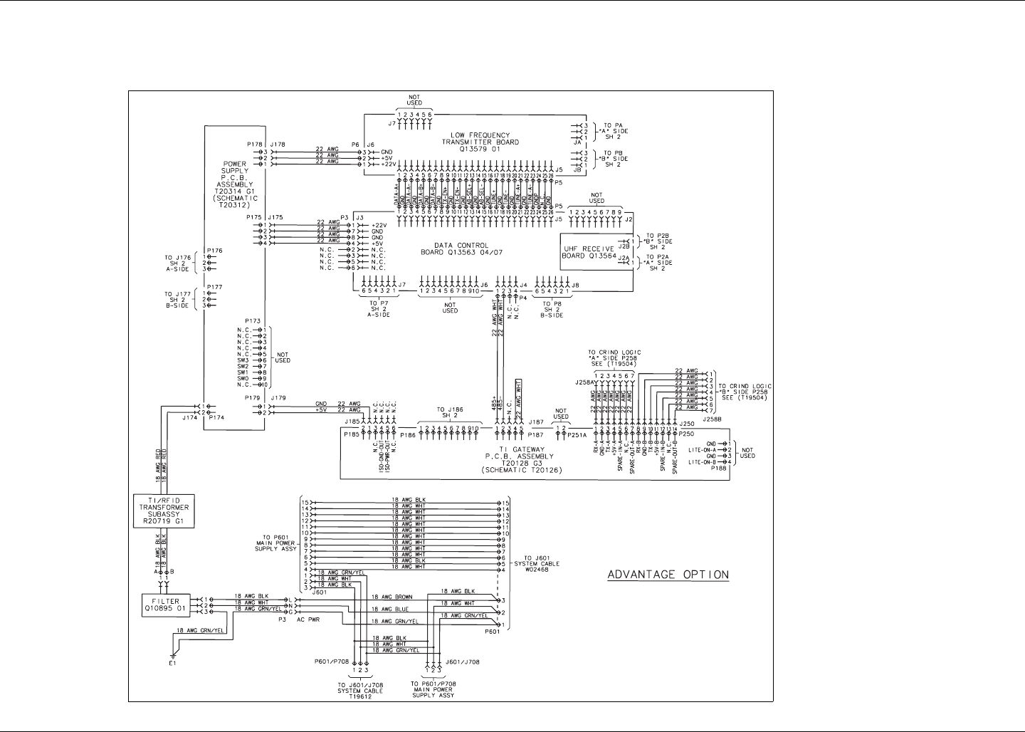
T20607 Interconnect Diagrams, Sheet 1 of 4, Revision H Appendix B - Cable Block Diagrams and Interconnects
MDE-3664B TRIND® Start-up, Service, and Parts Manual · June 2013 Page B-7
T20607 Interconnect Diagrams, Sheet 1 of 4, Revision H

Appendix B - Cable Block Diagrams and Interconnects T20607 Interconnection Diagrams, Sheet 2 of 4, Revision H
Page B-8 MDE-3664B TRIND® Start-up, Service, and Parts Manual · June 2013
T20607 Interconnection Diagrams, Sheet 2 of 4, Revision H
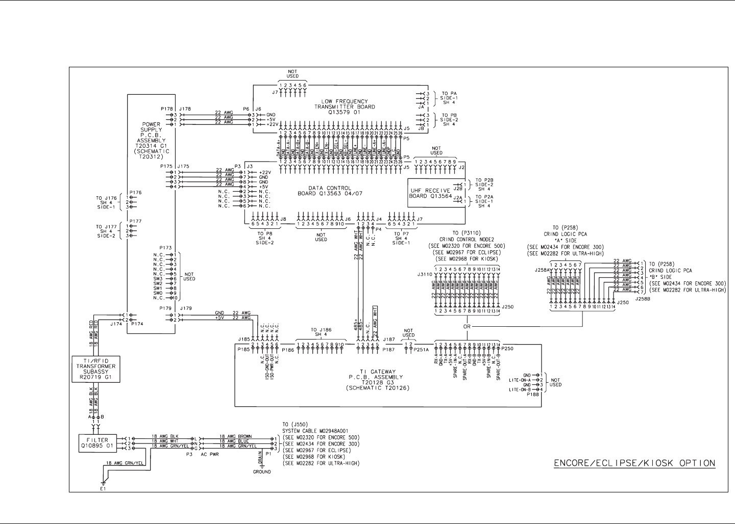
T20607 Interconnection Diagrams, Sheet 3 of 4, Revision H Appendix B - Cable Block Diagrams and Interconnects
MDE-3664B TRIND® Start-up, Service, and Parts Manual · June 2013 Page B-9
T20607 Interconnection Diagrams, Sheet 3 of 4, Revision H

Appendix B - Cable Block Diagrams and Interconnects T20607 Interconnection Diagrams, Sheet 4 of 4, Revision H
Page B-10 MDE-3664B TRIND® Start-up, Service, and Parts Manual · June 2013
T20607 Interconnection Diagrams, Sheet 4 of 4, Revision H
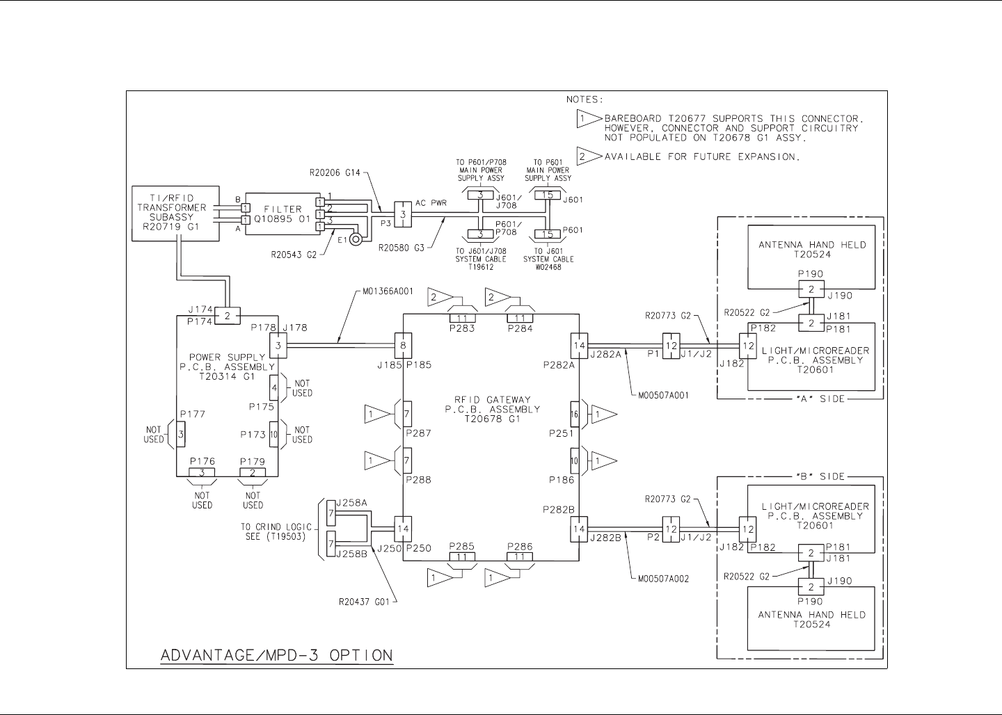
R20775 Cable Block Diagrams, Sheet 1 of 2, Revision D Appendix B - Cable Block Diagrams and Interconnects
MDE-3664B TRIND® Start-up, Service, and Parts Manual · June 2013 Page B-11
R20775 Cable Block Diagrams, Sheet 1 of 2, Revision D

Appendix B - Cable Block Diagrams and Interconnects R20775 Cable Block Diagrams, Sheet 2 of 2, Revision D
Page B-12 MDE-3664B TRIND® Start-up, Service, and Parts Manual · June 2013
R20775 Cable Block Diagrams, Sheet 2 of 2, Revision D

T20663 Interconnect Diagrams, Sheet 1 of 3, Revision C Appendix B - Cable Block Diagrams and Interconnects
MDE-3664B TRIND® Start-up, Service, and Parts Manual · June 2013 Page B-13
T20663 Interconnect Diagrams, Sheet 1 of 3, Revision C

Appendix B - Cable Block Diagrams and Interconnects T20663 Interconnection Diagrams, Sheet 2 of 3, Revision C
Page B-14 MDE-3664B TRIND® Start-up, Service, and Parts Manual · June 2013
T20663 Interconnection Diagrams, Sheet 2 of 3, Revision C

T20663 Interconnection Diagrams, Sheet 3 of 3, Revision C Appendix B - Cable Block Diagrams and Interconnects
MDE-3664B TRIND® Start-up, Service, and Parts Manual · June 2013 Page B-15
T20663 Interconnection Diagrams, Sheet 3 of 3, Revision C

© 2013 Gilbarco Inc. 7300
West Friendly Avenue · Post Office Box 22087
Greensboro, North Carolina 27420
Phone (336) 547-5000 · http://www.gilbarco.com · Printed in the U.S.A.
MDE-3664B The Advantage® Series, MPD®-3, Encore®, and Eclipse® Units · June 2013
Allen® is a registered trademark of Industrial Fasteners, Inc. EMC® is a registered trademark of Gilbarco Inc. Exxon® is a registered
trademark of Exxon Mobil Corporation. Phillips® is a registered trademark of The Phillips Screw Co. UL® is a registered trademark of
Underwriters’ Laboratories. Wayne® is a registered trademark of Dresser Industries, Inc.