Gilbarco MRIR3 Radio Frequency Identification Device User Manual
Gilbarco Inc. Radio Frequency Identification Device
Gilbarco >
Users Manual

PRELIMINARY
MDE-3801A TRIND™ Multi 1 Transmitter/Receiver in Dispenser Retrofit Kit • 07/00 Page 1
Introduction
Purpose of this Manual
This manual provides instruction for installing TRIND™ Multi 1 system for use in Marconi
products.
Important Notice This equipment has been tested and found to comply with the limits for a Class A digital
device pursuant to Part 15 of the FCC Rules. These limits are designed to provide reasonable
protection against harmful interference when the equipment is operated in a commercial
environment. This equipment generates, uses and can radiate radio frequency energy, and if
not installed and used in accordance with the instruction manual, may cause harmful
interference to radio communications. Operation of this equipment in a residential area is
likely to cause harmful interference in which case the user will be required to correct the
interference at his own expense. Changes or modifications not expressly approved by the
manufacturer could void the user’s authority to operate this equipment.
Required Reading If installing the equipment TRIND Multi 1 on gasoline dispensing equipment, the installer
must read, understand, and follow:
•this manual
• NFPA 30A, The Automotive and Marine Service Station Code
• NFPA 70, The National Electric Code
• applicable federal, state and local codes and regulations
Failure to do so may adversely effect the safe use and operation of the equipment.
Note: This kit must be installed by a Marconi ASC (Authorized Service Contractor) to insure
warranty.
Required Tools The following equipment may be needed to install all TRIND™ Multi 1 kits:
• Allen wrench set, American standard
• clean cloth or rag
• chip extraction tool, e.g., IC extraction, Digikey Part No. K158-ND or equivalent
• isopropyl alcohol (part# END-1082)
• needle nose pliers
• nut driver, 1/4'', 3/8''
• pocket knife
• Q12534 CRIND diagnostic card
• ratchet set, standard
• screwdrivers, flat and Phillips head
• static guard wrist strap
MDE-3801A
TRIND™ MULTI 1
Transmitter/Receiver in Dispenser
Retrofit Kits C00012-002-XX
Installation

PRELIMINARY
Parts List
Page 2 MDE-3801A TRIND™ Multi 1 Transmitter/Receiver in Dispenser Retrofit Kit • 07/00
Parts List
C00012-002 Kit
TRIND Multi 1 kits may be installed on a variety of Host Electronics (HE) systems. All kits
contain the parts detailed in table below. However, depending upon type of HE and equipment
receiving installation, additional parts or quantities of listed parts may be added to kits as
installation specific order entry items.
Q13781-01 Cable Group
Cable group Q13781-01 for all kits contains the following cables:
Description Part Number Quantity
cable group (see table “Q13781-01 Cable
Group” on page 2)
Q13781-01 1
card cage assembly T20538-G2 1
antenna/light assembly . T20582-G1 (see note 1)
T20609-G1 (see note 2)
M01296A001 (see note 3)
(see note 4)
jump jack Q11011-01 10
label plate, FCC N23936-01 1
manual, installation instructions MDE-3801 1
Notes:
1. For wide frame The Advantage Pumps and Dispensers only. Assembly includes
T20545-G2 Light Board and R20718-G1 Antenna Cable
2. For narrow frame The Advantage Pumps and Dispensers only. Assembly includes
T20545-G2 Light Board and R20718-G1 Antenna Cable
3. For Marconi Encore Series units only. Assembly includes M001058 Antenna
Assembly and M001055 Light Board.
4. Quantities determined at order entry.
Cables Part Number Quantity per kit
Gateway to CRIND logic R20437-G01 1
AC power R20580-G2 1
Light/Multi-protocol Reader R20665-GX
(see note 5)
(see note 6)
Gateway to Light/MPR/Power Boards R20724-G1 1
Notes:
5. Cable lengths (-GX) determined at order entry.
6. Quantity determined at order entry.
PRELIMINARY
MDE-3801A TRIND™ Multi 1 Transmitter/Receiver in Dispenser Retrofit Kit • 07/00 Page 3
Safety Information
Safety Information
Alert Symbol and Signal Words
Alert Symbol:
This is a standard ANSI* approved alert symbol. When you see this symbol, be alert to the
potential for a personal injury.
* Reference American National Standard Bulletins ANSI Z535.
Signal Words:
These signal words alert you to important safety hazards.
Safety Symbols: The following safety symbols are used throughout this manual to alert you to personal safety
hazards and precautions.
Explosive
Flammable
Electrical hazard
Use safety barricades
No people in area
No vehicles in area
Use emergency power disconnect
No open flames
No smoking
No power tools
Wear eye protection
Read all related manuals
Clean up spills
Turn power off
!
WARNING
The hazard or unsafe
practice may result in
severe injury or death.
!
CAUTION
The hazard or unsafe
practice could result in
minor injury.
The hazard or unsafe
practice will result in
severe injury or death.
!
DANGER
OFF

PRELIMINARY
Safety Information
Page 4 MDE-3801A TRIND™ Multi 1 Transmitter/Receiver in Dispenser Retrofit Kit • 07/00
Use Electrostatic Discharge Precautions
Place yourself at a neutral static-free potential by doing the following:
1Touch an unpainted metal surface.
2Use a wrist strap connected to a grounded metal frame or chassis.
Note: Failure to use electrostatic discharge precautions may damage electronic components
and void warranty.
Make sure all power has been removed from unit and CRIND.
Follow OSHA Lock-Out and Tag-Out Requirements
OSHA Standard 29 CFR 1910-147 Control of Hazardous Energy Sources (Lock-Out/Tag-Out)
covers ways to avoid personal injury if power is turned on or fuel pressure is applied
unexpectedly while servicing equipment. The rule requires that equipment power and fuel
under pressure be turned off and the device (breaker, valve, etc.) locked or labeled with a
warning tag.
Read OSHA Standard 29 CFR 1910-147 Control of Hazardous Energy Sources (Lock-Out/
Tag-Out). Station employees and service contractors need to understand and comply with this
program completely to ensure safety while the equipment is down.
Tag-Out and Lock-Out Procedure
Use plastic warning tags with signature/date blanks for Tag-Out. Sign and date them at shut
down. Attach tags with plastic connectors.
Use metal screw-down lock clamps or plastic single or multi-pole devices for Lock-Out of
breakers and switches. Always use a lock-out device whenever possible.
When working on electronics and electrical connections:
• Turn off unit power.
• Install lock-out device and tag on breaker(s).
OFF
PRELIMINARY
MDE-3801A TRIND™ Multi 1 Transmitter/Receiver in Dispenser Retrofit Kit • 07/00 Page 5
Installation
Installation
Installing Cables Note: Typical installation only (The Advantage Series).
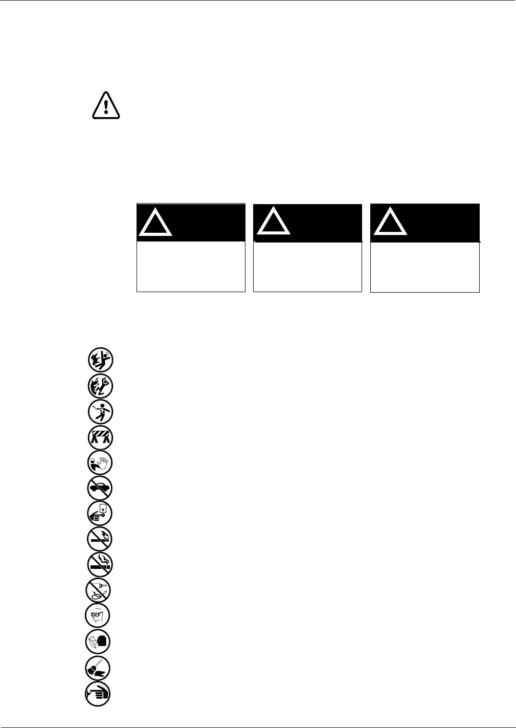
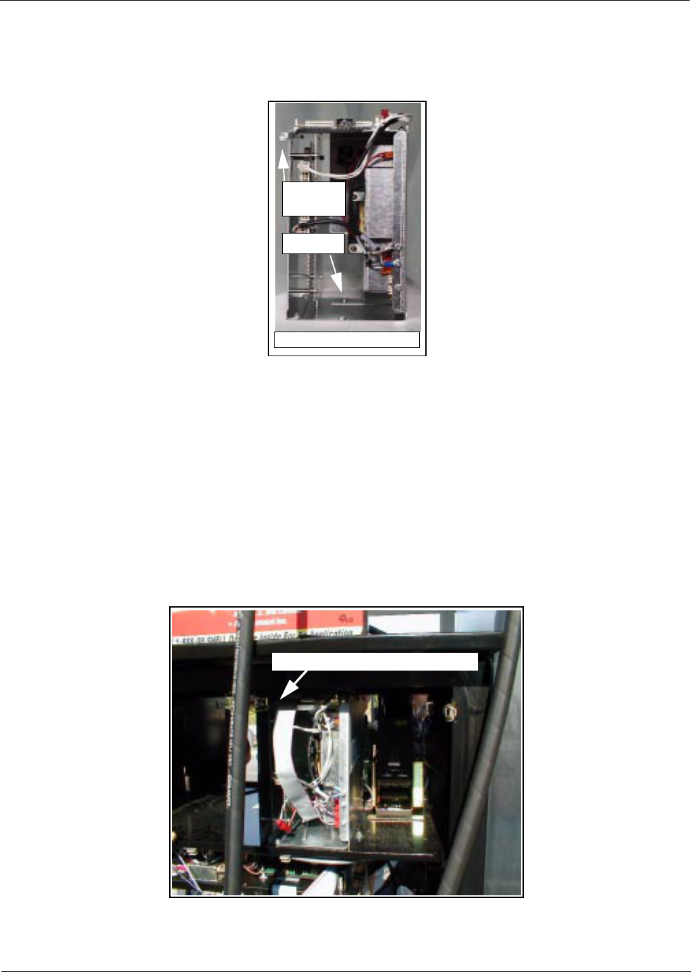
Position kit cables according to the following steps:
1Carefully pry out printer cable retainer from underside of printer shelf.
2Disconnect printer cable and pull cable out of 2 3/4" round hole from bottom.
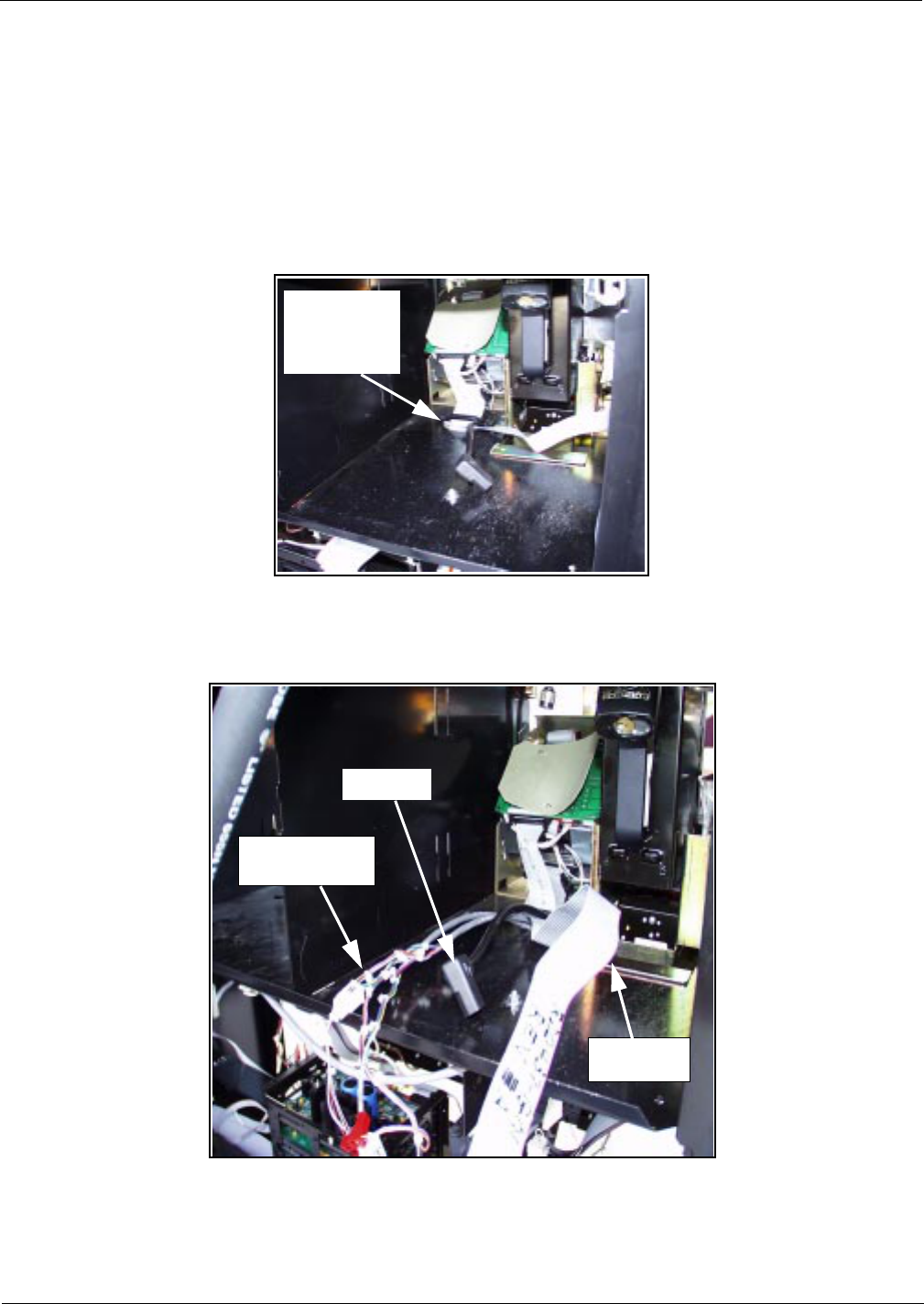
3Feed three-prong end of power cable R20580-G2, J250 end of R20437-G01 ribbon cable and
multiple connector ends of cables R20665-G1 and R20665-G2 up through hole and lay cable
ends toward A side.
4Reinstall printer cable and retainer disconnected and removed in step 2.
2 3/4” printer
cable hole
and cable
retainer
R20437-G01
ribbon cable
R20665-G1 and
R20665-G2 cables
R20580-G2
PRELIMINARY
Installation
Page 6 MDE-3801A TRIND™ Multi 1 Transmitter/Receiver in Dispenser Retrofit Kit • 07/00
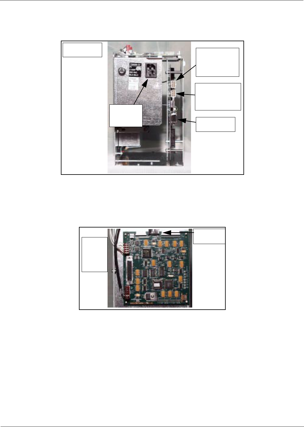
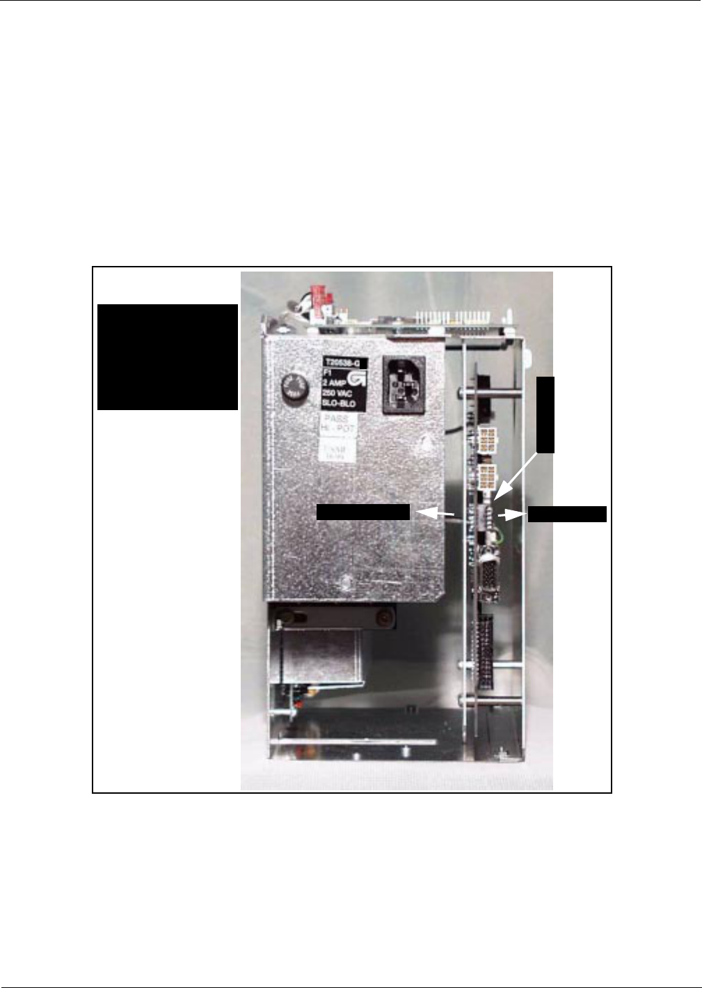
T20538-G2 Card CageConnection points on T20538-G2 card cage.
Note: For more cable connection detail see “Cable Block Diagram (Typical)” on page 12.
1Connect three prong female end of power cable R20580-G2 to card cage at location shown.
2Connect P7 on R20665-G1 to J7 and P8 on R20665-G2 to J8 on DCB at location shown.
3Connect J186 on R20724-G1 cable to P186 on Gateway Board on top of card cage.
J8 on DCB for
P8 on
R20665-G2 for
B side
J7 on DCB for
P7 on
R02665-G1 for
A side
RS232 Port
Rear side of card
cage shown
Connect
R20580-G2
power cable
For J186 on
R20724-G1
Gateway
board on
top of
card
cage
PRELIMINARY
MDE-3801A TRIND™ Multi 1 Transmitter/Receiver in Dispenser Retrofit Kit • 07/00 Page 7
Installation
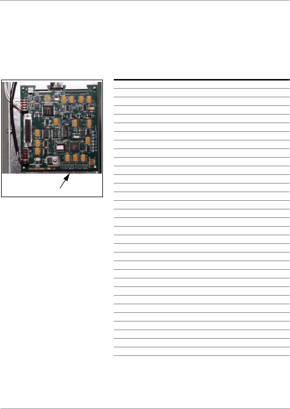
Address Gateway Board Before Installing Card Cage
Address on HE must and Gateway Board must be set to match.
MOC and Generic CRIND Addresses.
Address On CRIND Logic Board T17764-XX JP8 JP7 JP6 JP5 JP4
= Address on Gateway Board T20128 ‘A’ Side JP6 JP7 JP8 JP9 JP10
= Address on Gateway Board T20128 ‘B’ Side JP14 JP15 JP16 JP17 JP18
1 IN OUT OUT OUT OUT
2 OUT IN OUT OUT OUT
3 IN IN OUT OUT OUT
4 OUT OUT IN OUT OUT
5 IN OUT IN OUT OUT
6 OUT IN IN OUT OUT
7 INININOUTOUT
8 OUT OUT OUT IN OUT
9 INOUTOUTINOUT
10 OUT IN OUT IN OUT
11 IN IN OUT IN OUT
12 OUT OUT IN IN OUT
13 IN OUT IN IN OUT
14 OUTINININOUT
15 IN IN IN IN OUT
16 OUT OUT OUT OUT IN
17 IN OUT OUT OUT IN
18 OUT IN OUT OUT IN
19 IN IN OUT OUT IN
20 OUT OUT IN OUT IN
21 IN OUT IN OUT IN
22 OUT IN IN OUT IN
23 IN IN IN OUT IN
24 OUT OUT OUT IN IN
25 IN OUT OUT IN IN
26 OUT IN OUT IN IN
27 IN IN OUT IN IN
28 OUT OUT IN IN IN
29 IN OUT IN IN IN
30 OUTININININ
31 IN IN IN IN IN
32 OUT OUT OUT OUT OUT
Jump jack locations on Gateway Board
PRELIMINARY
Installation
Page 8 MDE-3801A TRIND™ Multi 1 Transmitter/Receiver in Dispenser Retrofit Kit • 07/00
Install card cage assembly (typical).
Note: Typical installation (The Advantage Series Dispensers) procedure showing mounting
and securing points on card cage.
1Locate tab at left front top of card cage.
2From B side, turn card cage sideways to unit, feed top and rear of card cage up and into shelf.
Note: Front of card cage will face B side.
3Position card cage so that tab fits over latch cutout for main door latch, securing card cage to
shelf divider.
• If two screws on card cage pass through shelf secure from underside of shelf with two nuts
provided in kit.
• If screws were removed, secure card cage from underside of shelf by installing one screw
removed in section “Connection points on T20538-G2 card cage.” on page 6 up through
hole in shelf to clinch nut on card cage (see illustration above). Dispose of second screw
and two nuts.
Tab on
card cage
card cage front facing B side
clinch nut
Tab locks into shelf divided at latch cut-out
PRELIMINARY
MDE-3801A TRIND™ Multi 1 Transmitter/Receiver in Dispenser Retrofit Kit • 07/00 Page 9
Installation
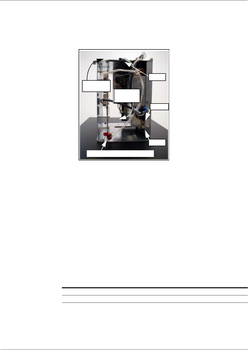
Connecting Remaining Cables
Note: Typical for The Advantage Series Dispensers. Connection points and cables are
universal.
1From A side, pass J250 end of cable R20437-G01, J176 and JA ends of cable R20665-G1 and
J177 and PA ends of cable R20665-G2 through card cage to B side.
2From B side, connect J176 on cable R20665-G1 to P176 on Power Supply PCB.
Note: Detailed information provided on “Cable Block Diagram (Typical)” on page 12.
3Connect J177 on cable R20665-G2 to P177.
4Connect JA on R20665-G1 to PA on R20724-G1 cable.
5Connect PA on R20665-G2 cable to JA on R20724-G1 cable.
6Connect J250 on ribbon cable R20437-G01 to P250 on Gateway board on top of card cage.
From A side of unit make the following connections:
On ribbon cable R20437-G01, connect J258A/B to P258 on HE (Host Electronics) as specified
in HE documentation.
Connect R20580-G2 power cable according to the following:
Note: Connections are unit specific. Use appropriate connectors to intercept power by
installing R20590-G1 inline.
For units with: Do the following:
System cable W02468 Install inline using 15 pin P601 and J601 connectors
System cable T19612 Install inline using 3 pin connectors J601/J708 and P601/P708
P186
P176
P177
JA and PA connectors on R20724-G1
pass cables
through cage
P250 on
Gateway Board
PRELIMINARY
Card Cage Set-Up
Page 10 MDE-3801A TRIND™ Multi 1 Transmitter/Receiver in Dispenser Retrofit Kit • 07/00
Card Cage Set-Up
Addressing Each operating unit (e.g., dispenser) on the HE controller must be addressed differently; no
two operating units may have the same address. Address is at discretion of the installer. Follow
these steps:
1Locate dip switches on power supply board (PCB) T20314-G1 in card cage.
2Using switches 2, 3, 4 and 5 address each operating unit according to the following table:
Note: Switch one in down position is standalone mode selected, used for service only.
Switch Numbers = Value
1 = Standalone Mode
2 = 1
3 = 2
4 = 4
5 = 8 1
2
3
4
5
Dip switch down Dip switch up
2

PRELIMINARY
MDE-3801A TRIND™ Multi 1 Transmitter/Receiver in Dispenser Retrofit Kit • 07/00 Page 11
Card Cage Set-Up
Testing TRIND™ Multi 1
1Restore power to HE unit.
2Present test tag at antenna from a distance of 6’’ or less. Light board should light and flash
sequentially.
Note: If light does not function properly, for multi-antenna HE units check to see if opposite
side of unit was activated, indicating a crossed cable.
Completing Installation
1Replace, close and/or secure all HE unit covers and/or doors.
2Affix FCC label plate under existing FCC label.
3Restore power to unit.
PRELIMINARY
Card Cage Set-Up
© 2000 Marconi Commerce Systems Inc.
7300 West Friendly Avenue • Post Office Box 22087
Greensboro, North Carolina 27420
Phone (336) 547-5000 • http://www.marconicommerce.com • Printed in the U.S.A.
MDE-3801A • 07/00
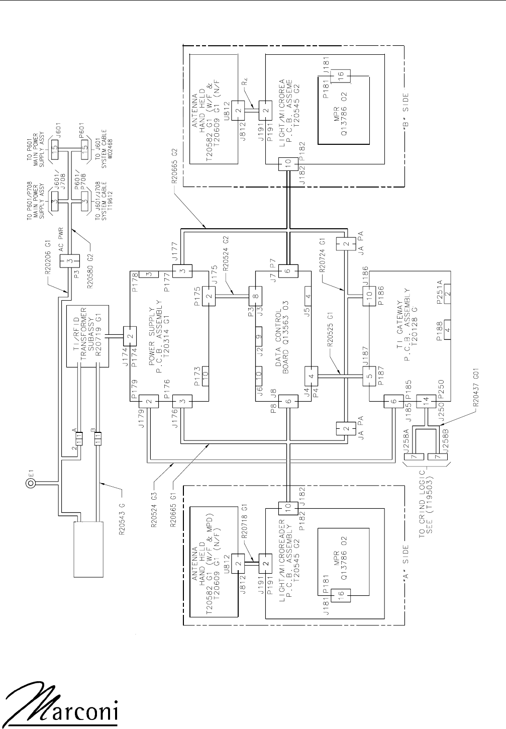
Cable Block Diagram (Typical)
2
FILTER
5
3
PRELIMINARY