Gilbarco MRIR4 RF Identification Device Module User Manual
Gilbarco Inc. RF Identification Device Module
UserManual.wiki
>
Gilbarco
>
MRIR4 User Manual
>
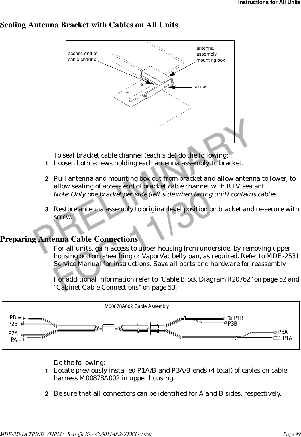
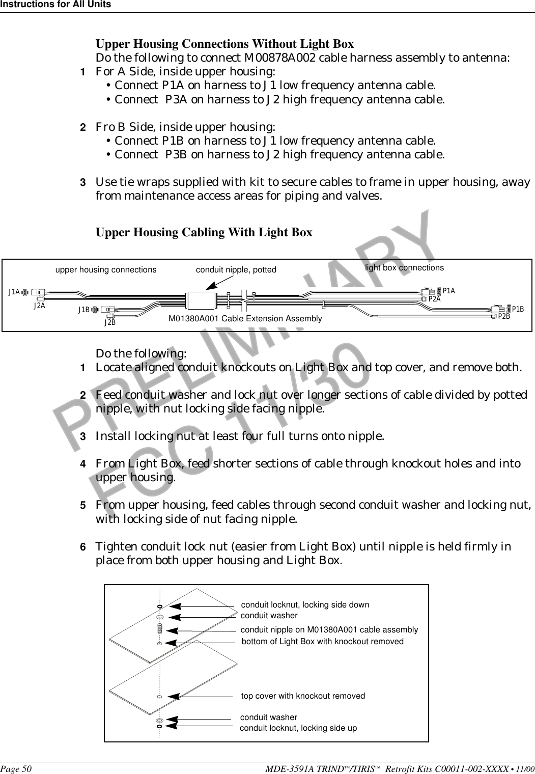
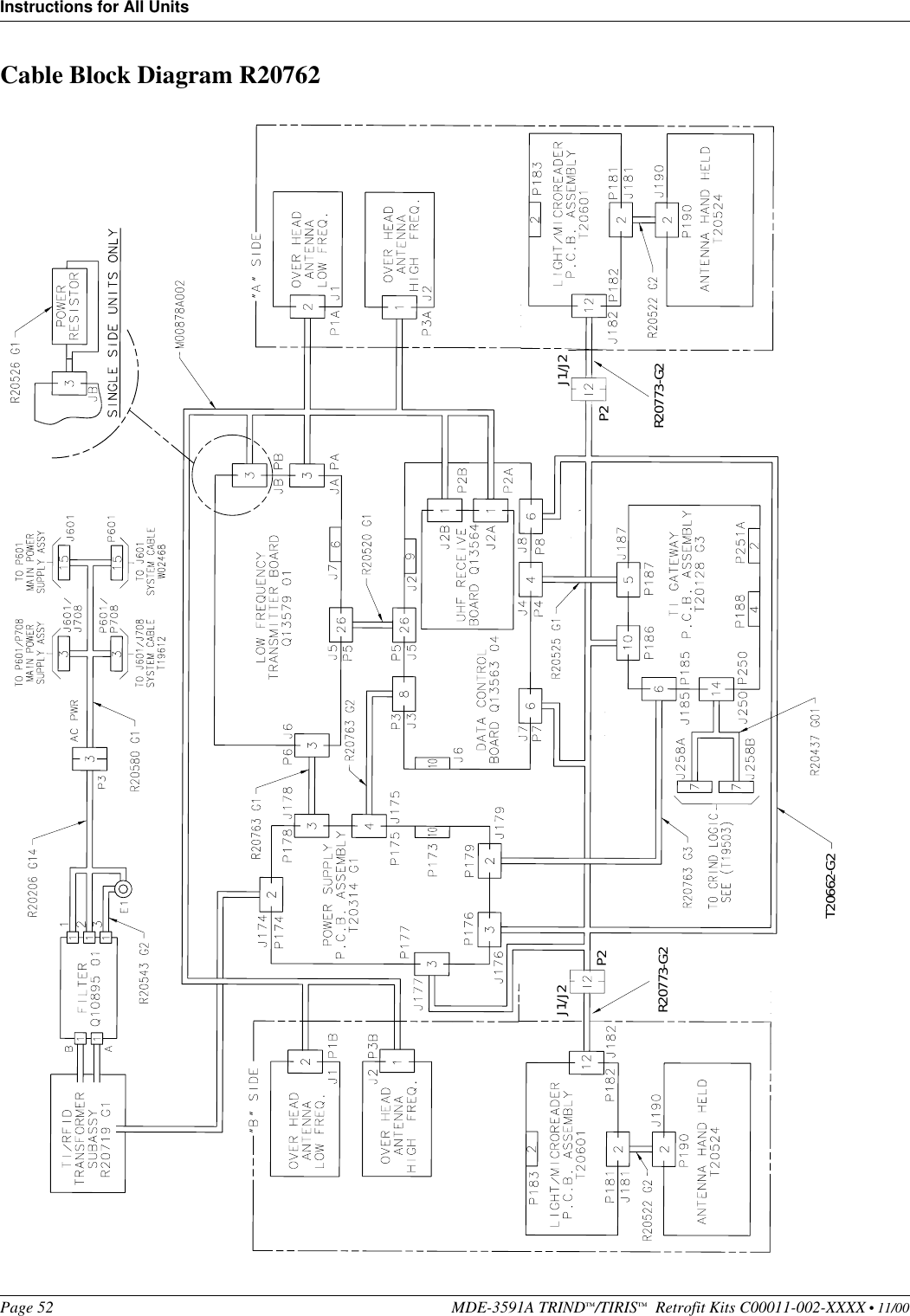
Users manual
Contents
1.
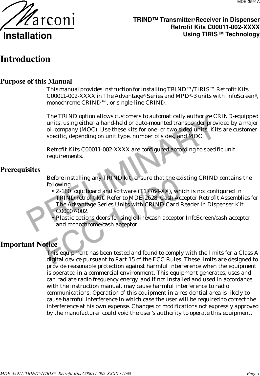
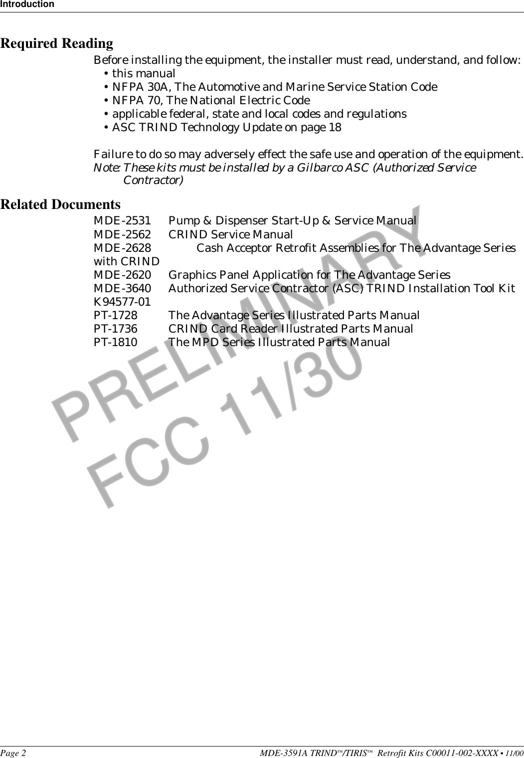
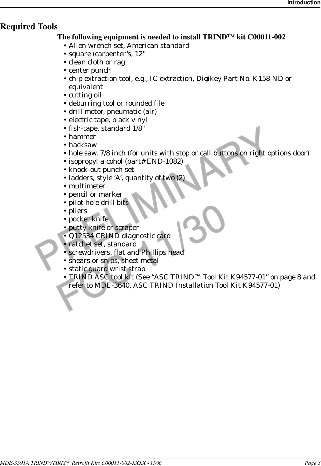
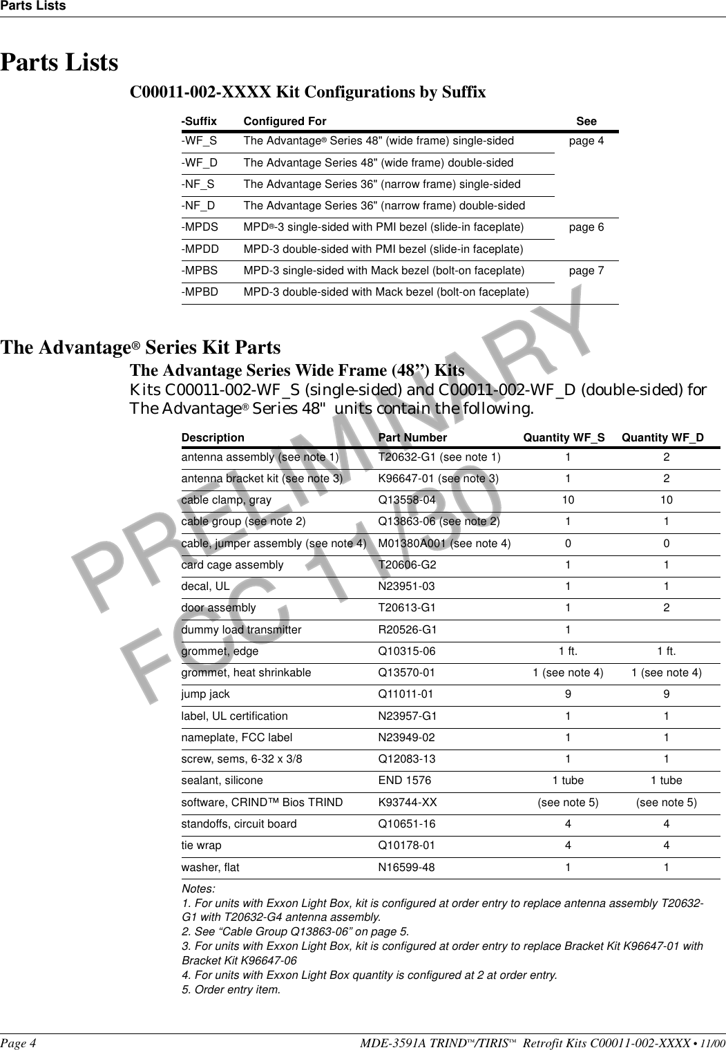
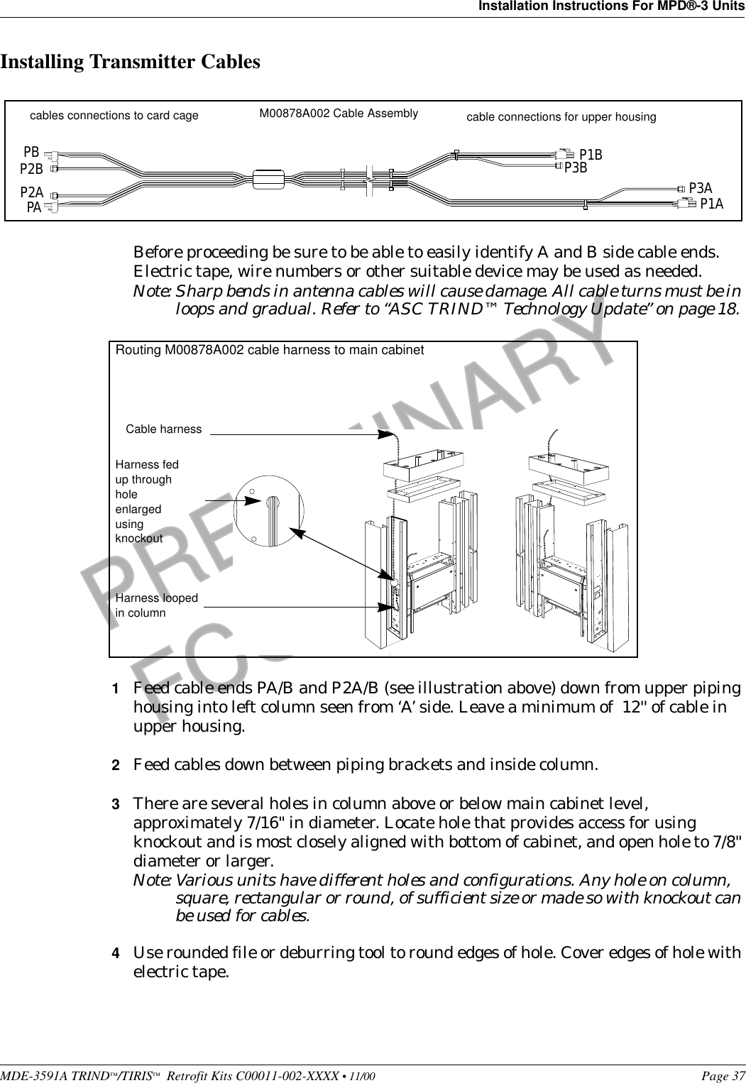
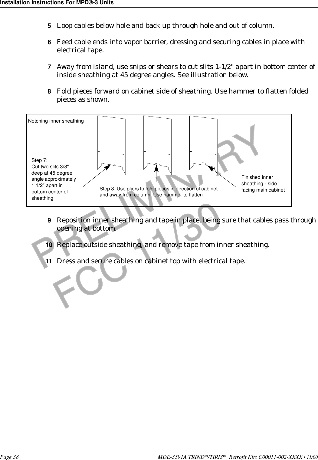
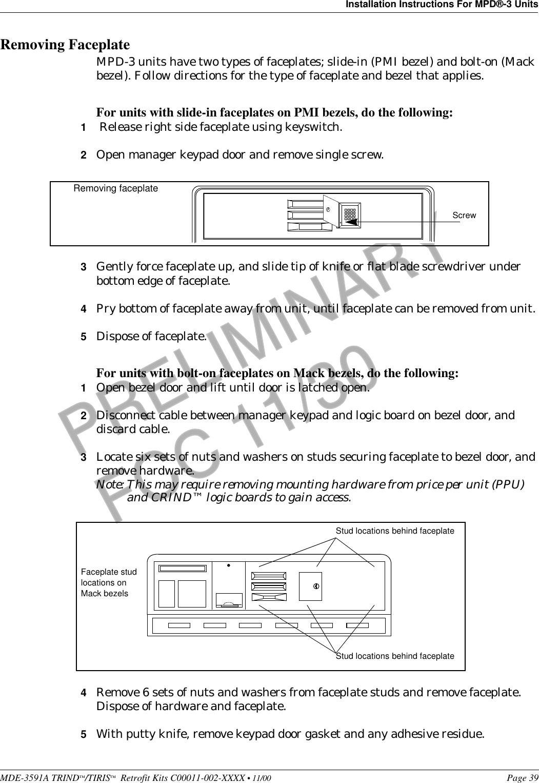
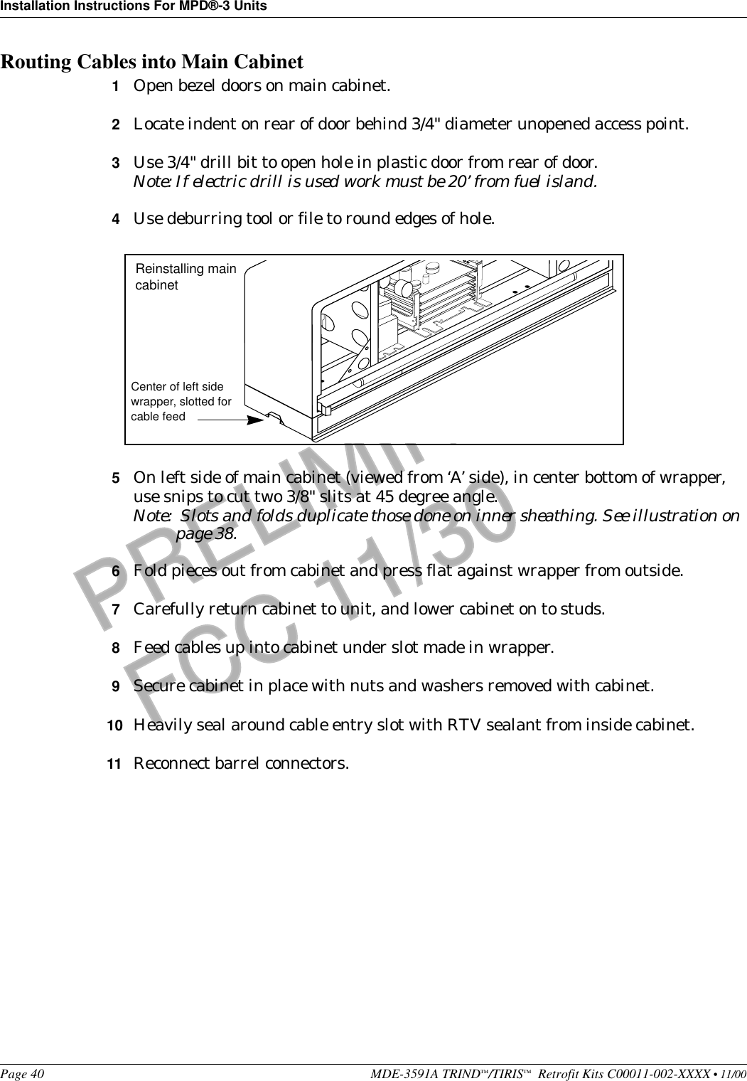
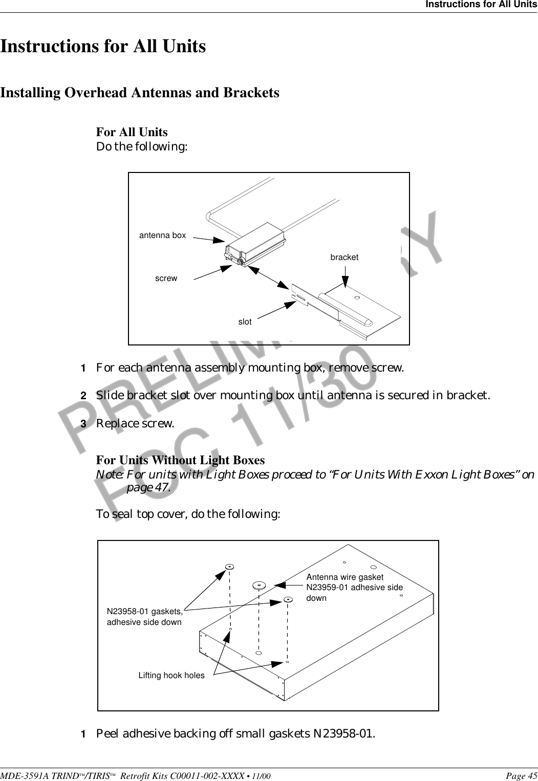
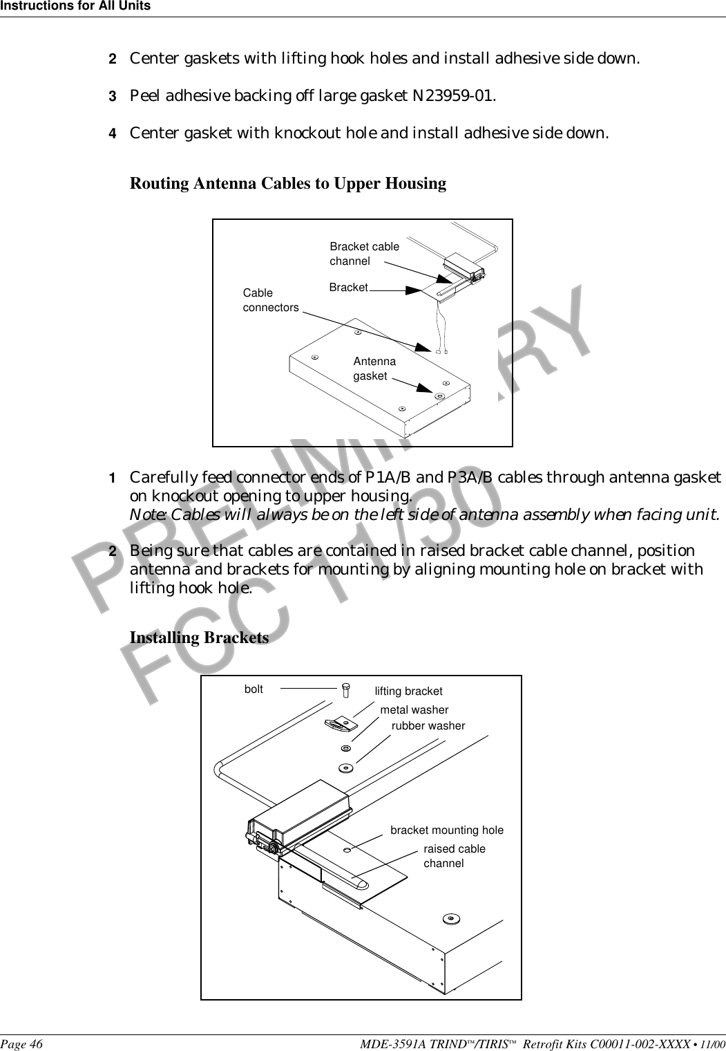
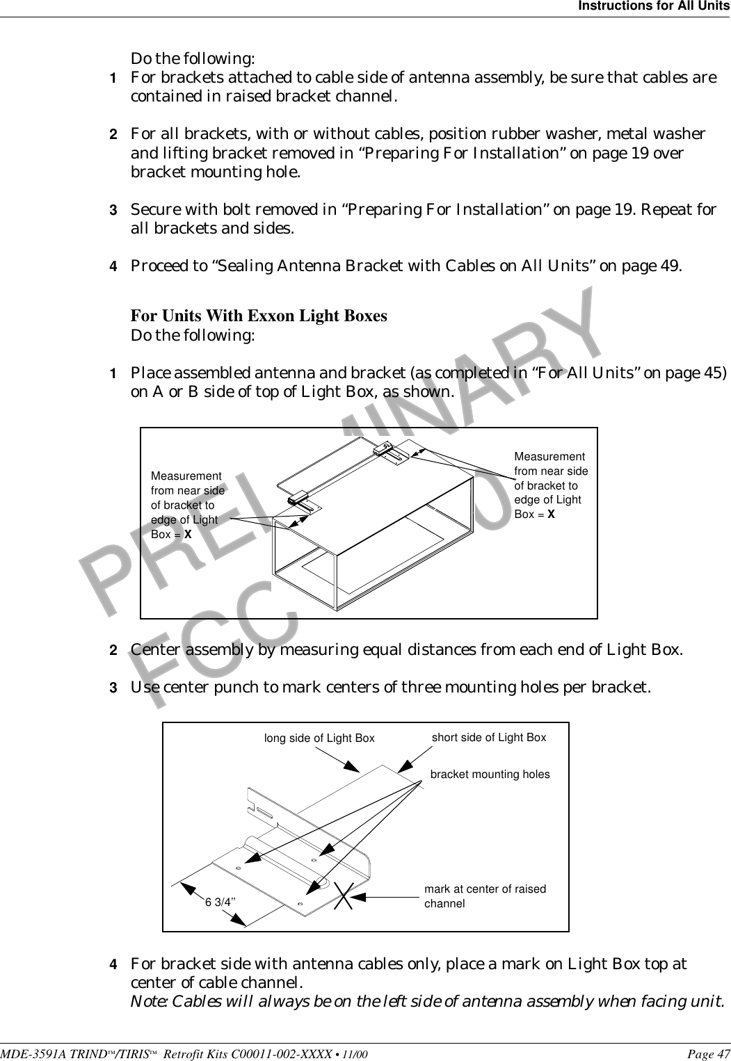
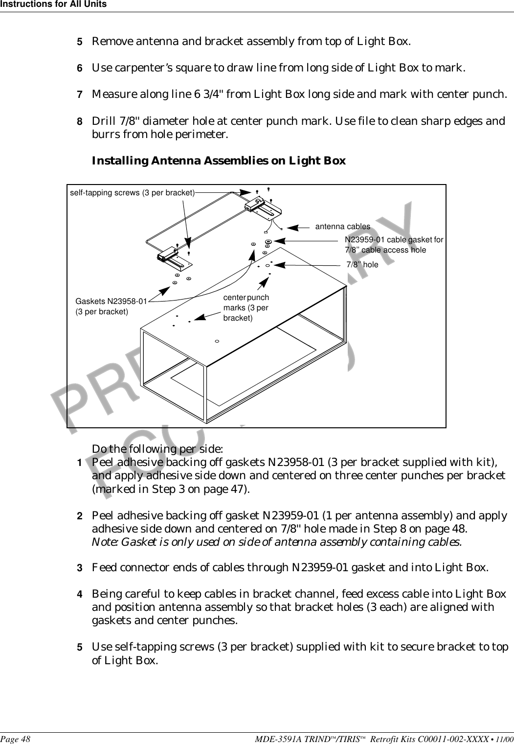
Users manual
2.
Cover letter for confidentiality
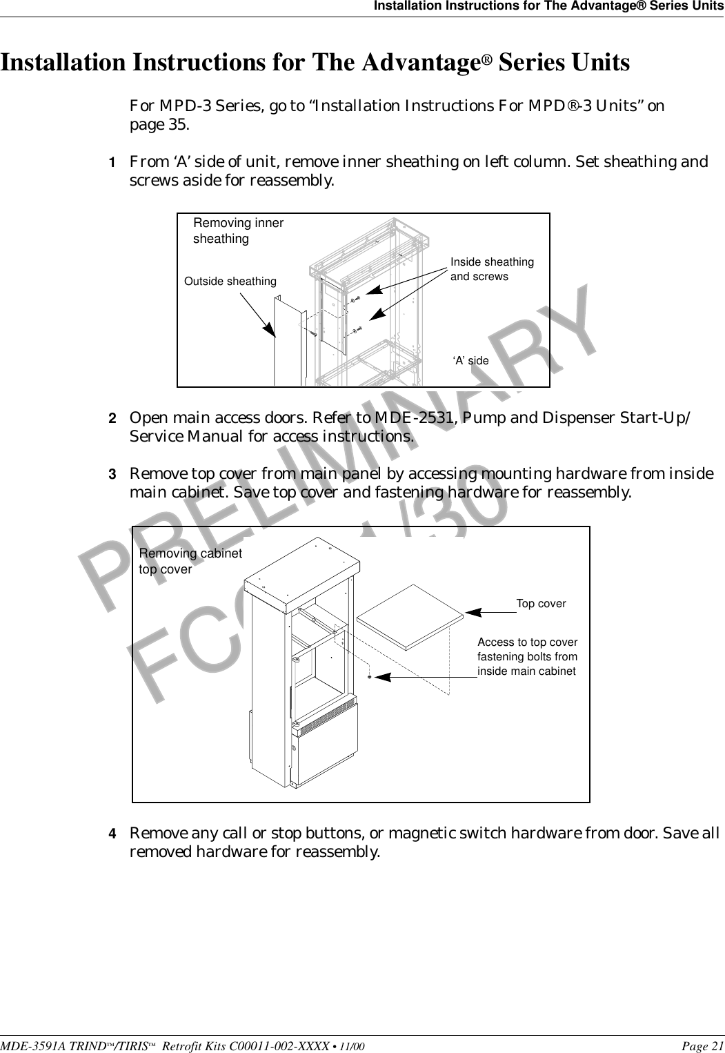
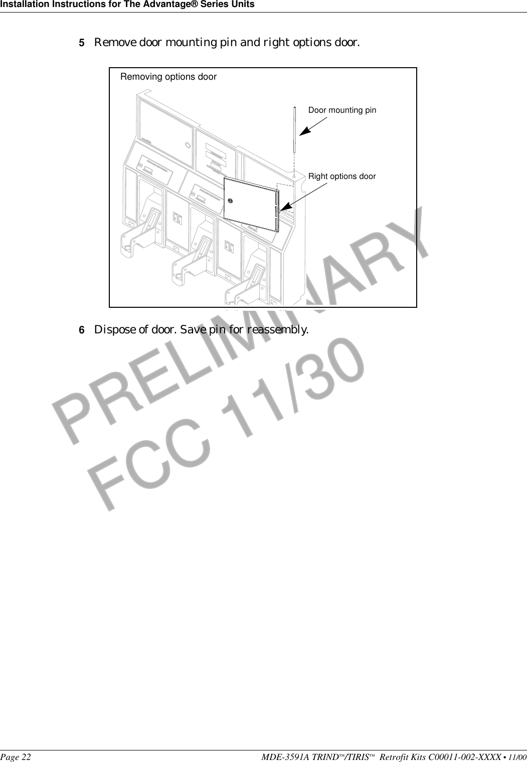
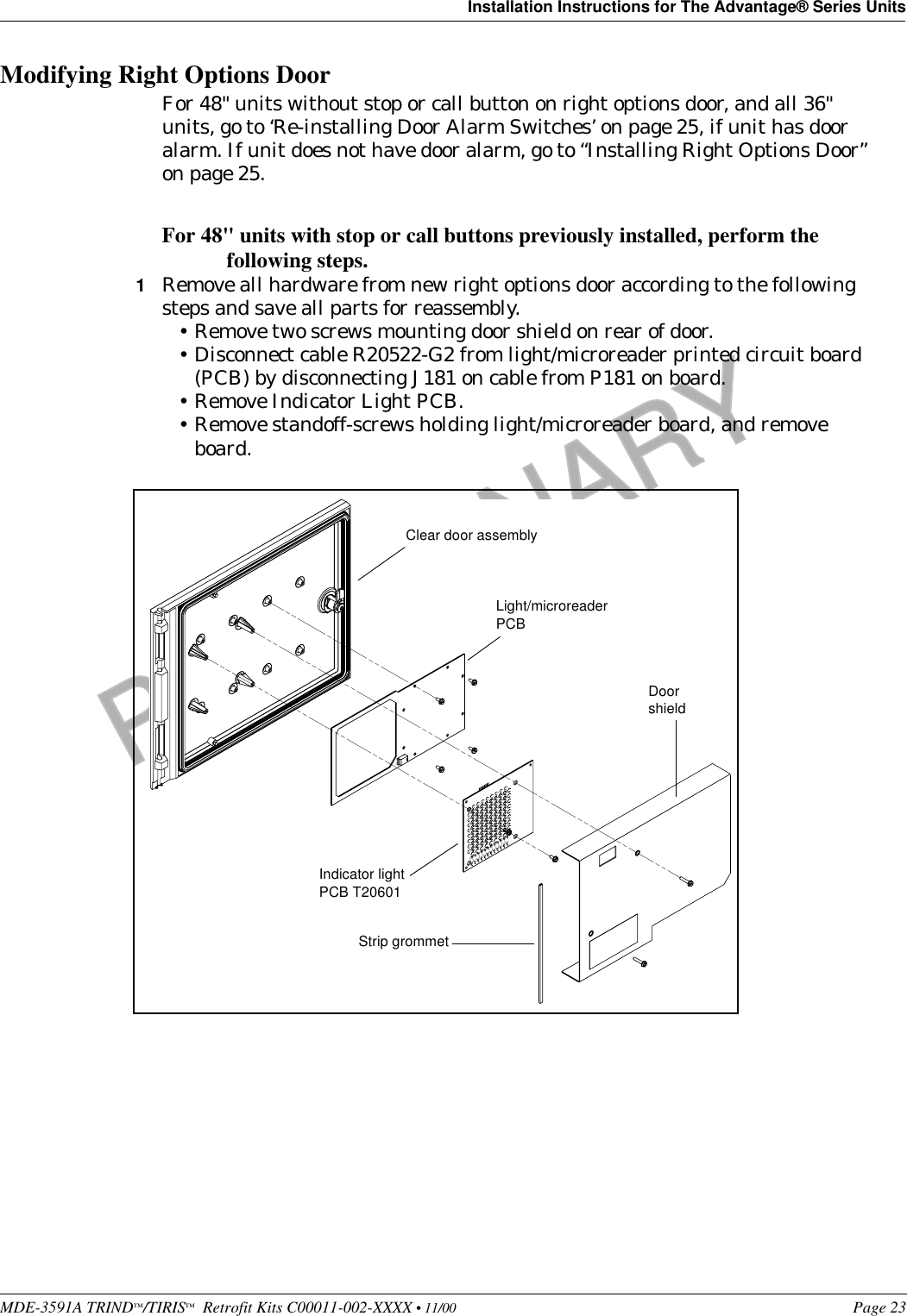
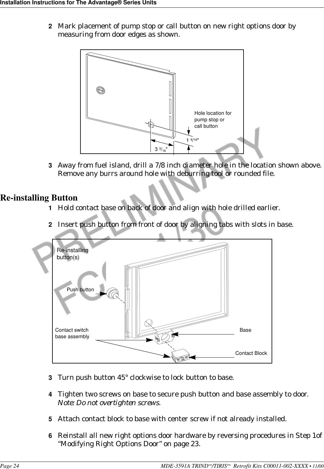
Users manual
Navigation menu
Upload a User Manual
Namespaces
Wiki Guide
HTML
PDF
Info
Views
User Manual
Discussion / Help
Navigation